

Page 1
OPERATING MANUAL
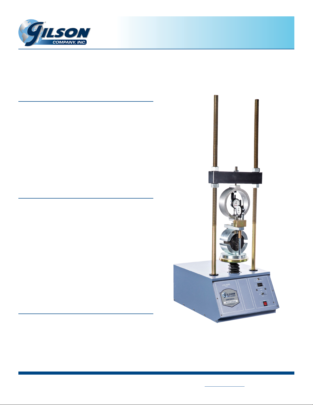
MS-398 and MS-398F Pro-Loader II Load Frame
0.02—2.0in/min, 10,000lbf
INTRODUCTION
The MS-398 Load Frame is one of our most versatile testing
units. The Pro Loader II can be utilized for the following soil tests:
California Bearing Ratio (CBR), Unconned Compression (UC),
Triaxial Compression, and Soil Cement. In addition, the following
Asphalt tests: Marshall, Lottman, TSR, IDT, SCB and Tack Coat shear
can all be performed. This unit also features strain rates – 0.02-
2.0in/min (0.508-50.8mm/min) – controlled to ±1% of set point.
Front panel controls allow the operator to adjust the direction
and speed of the platen, as well as select the strain rate. Sliding
the cross-arm up or down the coarse-threaded 1.25in (32mm)
diameter rods and tightening the nuts makes adjustment for the
wide variety of testing components quick and easy.
FEATURES
• Strain rate of 0.02-2.0in/min (0.508-50.8mm/min) allows for
multiple testing options (calibration chart included)
• Powerful 3/4hp DC drive motor
• Load capacity up to 10,000lbf (44kN)
• Durable 14-gauge steel cabinet and precision loading screw
with protective boot
• Hardened steel 8in (203mm) diameter platen, accepts a wide
variety of test xtures
• Heavy 1.25in (31.8mm) diameter vertical rods with coarse
threads
• Front panel controls
• Upper and lower limit indicator lights
• Three-position control switch has built-in hesitation to prevent
damage to the motor when reversing direction
• Corrosion-resistant components
UNPACKING & SET UP
1. Inspect your MS-398 for damage, remove it from the pallet.
2. Place the MS-398 on a sturdy, level surface such as a bench
top or HMA-94 Rolling Load Frame Cart.
MS-398 shown with MSA-860
(Continued on back.)
PHONE: 800-444-1508 P.O. Box 200, Lewis Center, Ohio 43035-0200
740-548-7298 E-mail: customerservice@gilsonco.com Product Web Page: www.globalgilson.com
Rev: 01/2019
FAX: 800-255-5314
740-548-5314
Page 2
3. Connect to grounded power supply with correct voltage and
amperage to output.
4. Adjust and level the crossarm to the appropriate height.
5. Install required Component Set and any accessories required
for testing.
CONTROLS
1. Main Power On/O: Includes an indicator light to show
when the power is on.
2. Platen Direction: Three-position switch (up, down and o)
includes built-in hesitation to prevent motor damage when
reversing direction.
3. Limit Lights: Indicate when upper and lower limits are at-
tained.
4. Strain Rate: Three-segment thumbwheel selector (strain
rate calibration chart included).
5. High-Speed Jog: Increases the speed of the platen when
the switch is pushed to the up position.
OPERATING INSTRUCTIONS
COMPONENT SETS
California Bearing Ratio (CBR)
ASTM D1883; AASHTO T 193
HMA-684 6,000lbf load ring, dial indicator, piston
HMA-685 10,000lbf load ring, dial indicator, piston
HMA-685D 10,000lbf load cell, LVT, readout box, piston
Soil Cement
ASTM D1632, D1633
HMA-687 10,000lbf load ring, dial indicator, 4 in platen
HMA-687D
ASTM D2850, D4764; AASHTO T 296, T 297
HMA-686 1,000lbf load cell, dial indicator
HM-413 1,000lbf load cell, LVT, Readout box
10,000lbf load cell , LVT, Readout box, 4 in platen
Triaxial
WARNING:
1. Read all safety and operating instructions before operating
2. Power the unit with the Main Power switch (indicator light
3. Based on the calibration chart (included), set the desired
4. Use the Platen Direction and High-Speed Jog switches to
5. Center the Platen Direction switch to the o position when
6. Refer to ASTM and/or AASHTO test methods for specic test
ELECTRIC SHOCK WARNING
Disconnect and lock out power supply when servicing the
unit or installing components.
the unit.
will show that the unit is on).
strain rate for the test using the three-segment thumbwheel
selector.
adjust the direction and speed of the platen for testing.
the test is complete.
instructions.
DISCONNECT AND LOCKOUT POWER
SUPPLY WHEN SERVICING THE UNIT
Unconned Compressive Strength
ASTM D2166; AASHTO T 208
HMA-681 500lbf load ring, dial gauge, plastic discs
HMA-683 1000lbf load ring, dial gauge, plastic discs
HMA-683D 1,000lbf load cell, dial gauge, plastic discs
Marshall Stability
ASTM D5581, D6927; AASHTO T 245, T 283
MSA-860 10,000lbf load ring, dial indicator
MSA-860D 10,000lbf load cell, LVT, readout box
Accessories
HMA-94 Rolling Load Frame Cart
 Loading...