

Page 1
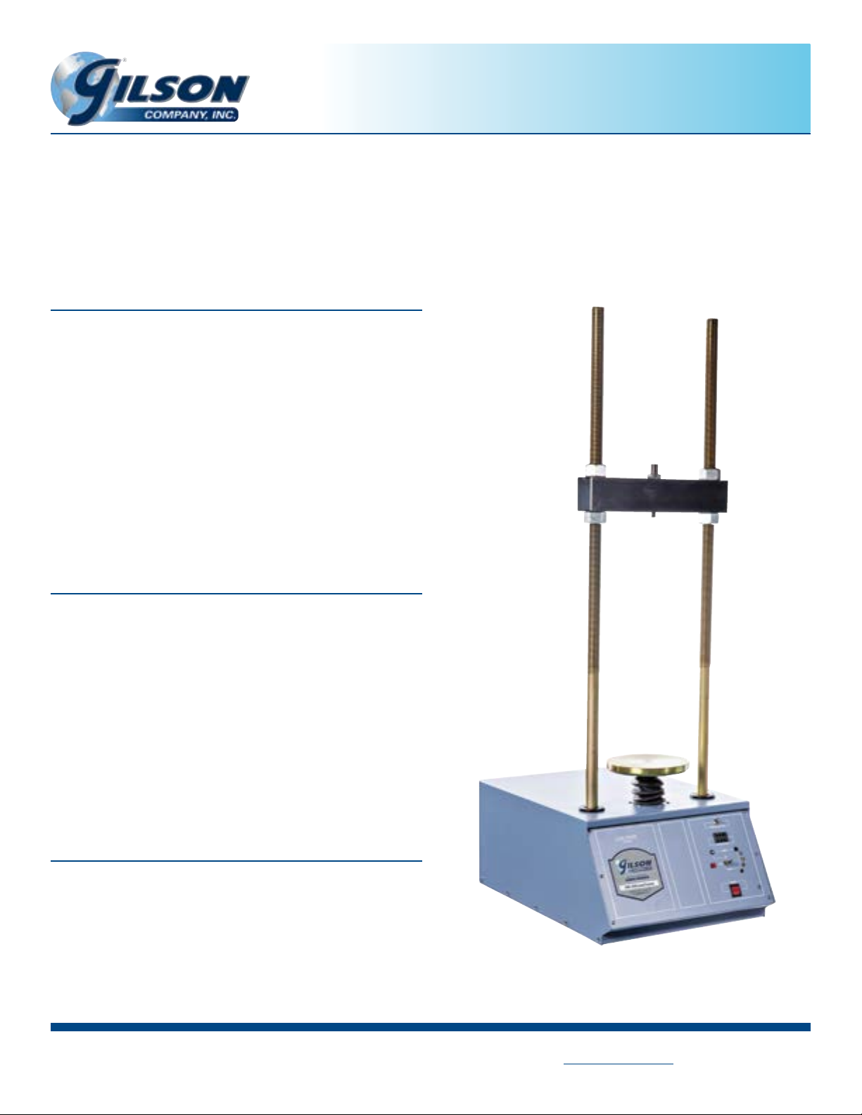
Gilson Pro-Loader Load Frame
20,000lbf (89kN), 0.00001—0.29999in/min
HM-399 and HM-399F
INTRODUCTION
The versatile HM-399 Pro-Loader Load Frame can be utilized for
multiple soil tests. Individual component sets can be tted to the
load frame to perform California Bearing Ratio (CBR), Unconned
Compressive Strength, Soil Cement, and Triaxial tests.
This 20,000lbf (89kN) capacity frame has a strain rate of
0.00001—0.29999in/min (0.000254—7.62mm/min) controlled
to +/- 1% of set point. Front panel controls allow the operator
to adjust the direction and speed of the platen. The strain rate
is set using thumbwheel selector. Sliding the cross-arm up or
down the coarse-threaded 1.25in (32mm) diameter rods and
tightening the nuts makes adjustment for the wide variety of
testing components quick and easy.
OPERATING MANUAL
FEATURES
• Precision adjustable strain rate of 0.00001—0.29999in/min
(0.000254—7.62mm/min) allows for multiple testing options
• Powerful 1/4hp DC drive motor
• Load capacity up to 20,000lbf (89kN)
• Maximum frame opening of 11.9 x 37.3in (302 x 947mm)
• Durable 14-gauge steel cabinet and precision loading screw
• Hardened steel 8in (203mm) diameter platen accepts a wide
variety of test xtures
• Heavy 1.25in (31.8mm) diameter vertical rods with coarse threads
• Front panel controls
• Upper and lower limit indicator lights
• Corrosion-resistant components
UNPACKING & SET UP
1. Inspect your HM-399 for damage, remove it from the pallet.
2. Place the Pro-Loader on a sturdy, level surface such as a bench
top or HMA-94 Rolling Load Frame Cart.
3. Connect to a properly grounded power supply with correct
voltage and amperage output.
4. Adjust and level the crossarm to the appropriate height.
5. Install required Component Set and any accessories required
for testing.
HM-399
(Continued on back.)
Rev: 01/2019
PHONE: 800- 444-1508 P.O. Box 200, Lewis Center, Ohio 43035-0200
740-548-7298 E-mail: customerservice@gilsonco.com Product Web Page: www.globalgilson.com
FAX: 800-255- 5314
740-548-5314
Page 2
FRONT PANEL CONTROLS
1. Main Power On/O: Switch is illuminated when ON.
2. Strain Rate: Thumb wheels are used to select the platen
speed.
3. Run: Sets the platen direction and operates the unit
continuously at the strain rate set by the thumb wheel.
4. Stop: Pressing the stop switch stops the platen movement.
5. Jog Button: Increases the speed of platen to the maximum
speed of the load frame jack screw (0.3in/min) when the
switch is pushed to the up position.
INDICATOR LIGHTS
1. Limit up, Red: The platen has reached the upper limit of
travel. No further movement upward is possible.
2. Up, Yellow: Shows the current direction of travel, when platen
is moving up.
3. Run, Green: The load frame is in operating mode at the speed
selected by the thumb wheels.
4. Down, Yellow: Shows the current direction of travel when
platen is moving down.
5. Limit down, Red: The platen has reached the lower limit of
travel. No further movement downward is possible.
COMPONENT SETS
California Bearing Ratio (CBR)
ASTM D1883; AASHTO T 193
HMA-684 6,000lbf load ring, dial indicator, piston
HMA-685 10,000lbf load ring, dial indicator, piston
HMA-685D 10,000lbf load cell, LVT, readout box, piston
Soil Cement
ASTM D1632, D1633
HMA-687 10,000lbf load ring, dial indicator, 4 in platen
HMA-687D
ASTM D2850, D4764; AASHTO T 296, T 297
HMA-686 1,000lbf load cell, dial indicator
HM-413 1,000lbf load cell, LVT, Readout box
10,000lbf load cell , LVT, Readout box, 4 in platen
Triaxial
OPERATING INSTRUCTIONS
ELECTRIC SHOCK WARNING
DISCONNECT AND LOCKOUT POWER
SUPPLY WHEN SERVICING THE UNIT
1. Read all safety and operating instructions before operating
the unit.
2. Connect the three-pronged plug to a properly wired grounded
receptacle with appropriate electrical current for the machine.
3. Install kit or individual components to measure load,
displacement, or other properties according to specic test
method.
4. Power the unit on with the main power switch.
5. Mount the selected test xture on the machine platen and
ensure it is centered. Raise or lower the platen with the JOG
switch so there is enough travel for the requirements of the
test without reaching the mechanical limit.
6. Set the desired strain rate using the thumb wheel selector.
7. Use the Run switch to select the desired direction of travel
by raising or lowering the switch. If a limit switch is active in
the chosen direction, as indicated by the red limit indicators,
the motor will not run. Once running, the appropriate yellow
direction and green RUN indicators will be illuminated. The
platen will run until the STOP button is pressed or a limit switch
is tripped.
8. After the test is complete, use the JOG or RUN switch to
reposition the platen.
Unconned Compressive Strength
ASTM D2166; AASHTO T 208
HMA-681 500lbf load ring, dial gauge, plastic discs
HMA-683 1000lbf load ring, dial gauge, plastic discs
HMA-683D 1,000lbf load cell, dial gauge, plastic discs
Accessories
HMA-94 Rolling Load Frame Cart
 Loading...