

Page 1

Setup Instructions
GX-271 Liquid Handler and GX-271 ASPEC™
GX-27X Series Z-Arm
(Part Number 260465)
This document contains instructions for setting up and installing the Z-arm on the GX-271 instruments. For complete
setup instructions, refer to the user’s guide included on the documentation CD that is shipped with the instrument.
Warning! All of the components on the Z-arm must be installed before the Z-arm is attached to the instrument. Do not
install the Z-arm until instructed to do so in this document.
The Z-arm and its components should be assembled and installed in the following order:
1 Isolator Probe Holder Installation
2 Guide Foot Installation
3 Fraction Collection Valve Installation (Optional)
a) Low Mount
4 Z-Arm Installation
5 Adjusting the Z Travel Height
6 Probe Installation
7 LLD (Liquid Level Detection) Cable Installation
8 Final Z-Arm Height Adjustment
Technical Specifications
Technical Specification Definition
Arm speed
Vertical punch strength
125 mm/sec in Z dimension
4.5 kg (10.0 lb)
Phone: 608-836-1551 • Fax: 608-831-4451 • E-mail: sales@gilson.com, service@gilson.com, training@gilson.com • www.gilson.com
3000 Parmenter Street • P.O. Box 620027 • Middleton, WI 53562-0027 USA
Gilson S.A.S. • 19, avenue des Entrepreneurs, BP 145, F-95400 VILLIERS LE BEL France
©2008 Gilson, Inc. All rights reserved. LT319636-04
Gilson, Inc. World Headquarters
Page 2
Isolator Probe Holder Installation
Follow the instructions below to install the isolator probe holder
(part number 2604615) on the isolator mounting block on the Z-arm.
Note: The isolator mounting block is factory-installed. Do not remove it
from the Z-arm.
1 Using the 3 mm Allen wrench included in the GX-27X accessory package,
remove the screw from the bottom of the isolator mounting block on the
Z-arm.
2 Slide the isolator mounting block down as far as it will go to the bottom of
the Z-arm.
Note: There may be some resistance when sliding the isolator mounting
block.
3 Lay the Z-arm on its back on a flat surface.
4 Orient the isolator probe holder so that the D notch is at the top and the
connector for the LLD cable is facing out. Place the D notch in the isolator
probe holder over the lower part of the isolator mounting block.
isolator mounting
block
LLD cable
connector
isolator probe
holder
5 Place the screw removed in step 1 up through the bottom of the isolator
probe holder and into the isolator mounting block and tighten using the
3mm Allen wrench.
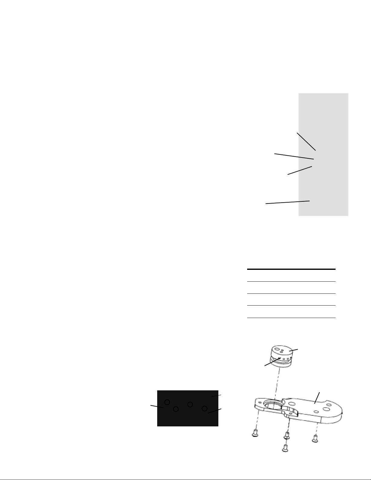
Guide Foot Installation
The guide foot (ordered separately) includes the probe guide insert and four
screws.
There are different size probe guide inserts available depending on the outer
diameter of the probe being used. Each insert is marked with a number of spots.
Refer to the table on the right for more information.
The guide foot is installed on the Z-foot of the Z-arm.
1 Lay the Z-arm on its back on a flat surface.
2 Locate the probe guide insert and place it on the top of the guide foot. The
probe guide insert should be oriented so the wider part is at the bottom and
the three holes are at the top.
3 Place the guide foot below the Z-foot and align the holes on the guide foot
with the holes on the Z-foot.
4 Place the four Phillips screws
through the bottom of the guide
foot into the Z-foot and tighten.
Z-foot
Z-arm
guide
foot
3 mm
Allen wrench
Insert Number of Spots
1.3 mm 0
1.5 mm 1
1.8 mm 2
2.3 mm 3
2.7 mm 4
probe guide insert
spots
guide foot
guide foot installed on Z-foot
Page 2 of 5 LT319636-04
Phillips
screws
Page 3

Fraction Collection Valve Installation (Optional)
Low Mount
The fraction collection valve is installed on the guide foot.
To install the fraction collection valve:
1 Place the valve on top of the guide foot as shown in the photo. Align the two
holes on the bottom of the valve with the holes on the guide foot. Attach the
valve to the guide foot using the two Phillips screws included with the valve.
2 Connect the black wiring from the top of the valve to the FC VALVE port on
the side of the Z-arm.
Tube and Wire Routing Strip Installation
FC valve installed
on the guide foot
The tube and wire routing strip is included with the fraction collection valve.
To install the tube and wire routing strip:
1 Using the 3 mm Allen wrench included in the accessory
package, loosen the stop pin so that it is flush with the
right side of the Z-arm.
Note: The stop pin is installed on the left side of the
Z-arm in the hole labeled S2.
2 Orient the tube and wire routing strip so that the side
with two smaller notches is on the left.
3 Slide the tube and wire routing strip over the two raised
rails on the right side of the Z-arm. The notch should
line up with the hole in the Z-arm for the stop pin.
4 Fully tighten the stop pin. The tip of the stop pin should
be visible on the right side of the Z-arm.
left side of Z-arm
Z-Arm Installation
Follow these steps to install the Z-arm:
tube and wire
routing strip
notches
S2
Note: Plumbing
connections are
described in the
instrument’s user’s
guide.
Y-a rm
Z-arm
1 Using the 3 mm Allen wrench included in the accessory package, loosen the
mounting screw on the Z-arm mounting bracket located on the Y-arm. Turn
counterclockwise to loosen.
2 Partially pull out the bracket. Do not remove completely.
3 Place the Z-arm into the mounting bracket. You will need to insert one side
of the Z-arm into place at a time (back to front).
4 Tighten the screw on the mounting bracket until the Z-arm is secure.
5 The Z-arm will be set to its proper height as the final step of the installation.
This adjustment is described on page 5.
Page 3 of 5 LT319636-04
mounting
screw
Page 4

Adjusting the Z Travel Height
The Z travel height is set by default to the S2 position (for 125 mm probes).
Follow these steps to adjust the Z travel height:
1 Using the 3 mm Allen wrench included in the accessory package, remove
the stop pin (part number 260463) from the Z-arm. The stop pin is installed
on the left side of the Z-arm in the hole labeled S2.
stop pin
Note: If you will be setting the Z travel height to 175 mm, you will not use
the stop pin. If the stop pin is not being used, it should be stored for future
use.
2 Insert the stop pin in the proper hole on the left side of the Z-arm.
• S1 for 56 mm probes
• S2 for 125 mm probes
• No pin installed for 175 mm probes
S2
S1
left side of Z-arm
3 Using the 3 mm Allen wrench, tighten the head of the stop pin until it
reaches a hard stop.
Note: The stop pin is inserted in a hole on the left side of the Z-arm and as
it is tightened should enter the adjacent hole on the right side of the Z-arm.
The tip of the stop pin is visible on the right side of the Z-arm.
Probe Installation
There are different probes available for use on the instrument. Depending upon
your application, you have purchased the appropriate probe and guide foot.
When installing the probe, refer to the following procedure and diagram that
show where they are installed on the Z-arm.
To install the probe on the Z-arm, insert the probe into the top of the isolator
probe holder and pull it through until the tip of the probe is in the probe guide
insert.
Z-arm
stop pin
Z-arm
isolator probe holder
probe guide insert
Page 4 of 5 LT319636-04
Page 5

LLD (Liquid Level Detection) Cable Installation
To install the liquid level detection cable assembly (part number 260461126):
strain relief
LLD
cable
1 Tighten the hex nut on the front of the isolator probe holder.
2 Place the metal slot end of the cable over the metal tab on the isolator probe
holder.
3 Place the strain relief in the bracket at the top of the Z-arm.
4 Plug the other end of the cable into the LLD port on the right side of the
Z-arm.
Before proceeding with the final Z-arm height adjustment, complete all of the
installation steps for the instrument, including locator pan installation,
accessory installation, rear panel connections, and plumbing connections.
These instructions can be found in Chapter 2, Installation, in the user’s guide
included on the documentation CD that is shipped with the instrument.
Final Z-Arm Height Adjustment
Follow these steps to adjust the Z-arm to the proper height.
1 Locate one of the Z-height adjustment tools that was shipped with the
instrument.
LLD port
isolator probe
holder
Y-a rm
Z-arm
2 Using the 3 mm Allen wrench included in the accessory package, loosen the
mounting screw on the Z-arm mounting bracket and slightly raise the
Z-arm.
3 Place the Z-height adjustment tool under the Z-foot of the Z-arm.
4 While holding the adjustment tool in place, use the other hand to carefully
lower the Z-arm until it lightly rests on the adjustment tool.
5 Tighten the mounting screw on the Z-arm mounting bracket so the Z-arm is
secure.
6 While holding the adjustment tool in place, slide the Z-arm off the tool.
Ensure that the bottom of the Z-arm lightly rubs against the adjustment tool
as it moves. Repeat steps 2 through 5 until this is true.
mounting
screw
Z-foot
Page 5 of 5 LT319636-04
 Loading...