

Page 1

508 Interface Module User’s Guide
Page 2

Page 3

508 Interface Module User’s Guide
World Headquarters
Gilson, Inc.
3000 Parmenter Street
P.O. Box 620027
Middleton, WI 53562-0027 USA
Telephone: 608-836-1551 Fax: 608-831-4451
www.gilson.com
sales@gilson.com, service@gilson.com, training@gilson.com
Gilson S.A.S.
19, avenue des Entrepreneurs
F-95400 VILLIERS LE BEL
France
©2006 Gilson, Inc. All Rights Reserved. LT302003-01
Page 4

Page 5

Table of Contents
1 Introduction
Unpacking . . . . . . . . . . . . . . . . . . . . . . . . . . . . . . . . . . . . . . . . . . . . . . . . . . . 1-2
Standard Equipment . . . . . . . . . . . . . . . . . . . . . . . . . . . . . . . . . . . . . . 1-2
Documentation . . . . . . . . . . . . . . . . . . . . . . . . . . . . . . . . . . . . . . . . . . 1-2
Customer Service . . . . . . . . . . . . . . . . . . . . . . . . . . . . . . . . . . . . . . . . . . . . . 1-3
Technical Specifications . . . . . . . . . . . . . . . . . . . . . . . . . . . . . . . . . . . . . . 1-4
2 Installation
Electrical Connections . . . . . . . . . . . . . . . . . . . . . . . . . . . . . . . . . . . . . . . . 2-2
Rear Panel . . . . . . . . . . . . . . . . . . . . . . . . . . . . . . . . . . . . . . . . . . . . . . . . 2-2
3 Operation
Status Lights . . . . . . . . . . . . . . . . . . . . . . . . . . . . . . . . . . . . . . . . . . . . . . . . . 3-2
4 Maintenance
5 Troubleshooting
Troubleshooting Chart . . . . . . . . . . . . . . . . . . . . . . . . . . . . . . . . . . . . . . . . 5-2
Repair and Return Policies . . . . . . . . . . . . . . . . . . . . . . . . . . . . . . . . . . . . 5-3
Before Calling Us . . . . . . . . . . . . . . . . . . . . . . . . . . . . . . . . . . . . . . . . . 5-3
Warranty Repair . . . . . . . . . . . . . . . . . . . . . . . . . . . . . . . . . . . . . . . . . . 5-3
Non-Warranty Repair . . . . . . . . . . . . . . . . . . . . . . . . . . . . . . . . . . . . . 5-3
Rebuilt Exchange . . . . . . . . . . . . . . . . . . . . . . . . . . . . . . . . . . . . . . . . . 5-3
Return Procedure . . . . . . . . . . . . . . . . . . . . . . . . . . . . . . . . . . . . . . . . . 5-4
Unit End-of-Life . . . . . . . . . . . . . . . . . . . . . . . . . . . . . . . . . . . . . . . . . . . 5-4
Gilson 508 Interface Module User’s Guide
Page 6

Page 7

Introduction 1
The Gilson 508 Interface Module connects your computer to many instruments made by Gilson. It
permits bi-directional communication by interconverting the RS-232 signal levels used by computers
and the RS-422/485 signal levels required by the Gilson Serial Input/Output Channel (GSIOC).
Gilson 508 Interface Module User’s Guide 1-1
Page 8

Introduction
1
Unpacking
Unpack the interface module and its accessories carefully from the carton.
Unpacking
Verify that all parts are included and are undamaged.
Do this now, even if the interface module will not be used immediately. Many
carriers must receive concealed damaged claims within seven days of delivery.
Please retain all packing material so the unit may be shipped safely, if necessary.
Standard Equipment
Once the instrument and the accessories have been unpacked, you should have
the following:
• 508 Interface Module
• RS-232 cable
•power supply
• Euro plug adapter
Documentation
The following documents are included with the 508 Interface Module:
• 508 Interface Module Documentation CD
• Declaration of Conformity
1-2 Gilson 508 Interface Module User’s Guide
Page 9

Introduction
Customer Service
Gilson, Inc. and its worldwide network of authorized representatives provide
customers with the following types of assistance: sales, technical support,
applications, and instrument repair.
If you need assistance, please contact your Gilson-authorized representative.
Specific contact information can be found on the Gilson website at
www.gilson.com. To help us serve you quickly and efficiently, please refer to
Repair and Return Policies on page 5-3.
1
Customer Service
Gilson 508 Interface Module User’s Guide 1-3
Page 10

Introduction
Technical Specifications
1
Technical Specifications
Please be aware of the following before connecting the interface module.
Warning! Changes or modifications to the interface module not expressly
approved by Gilson could void the factory-authorized warranty.
The interface module has been tested and found to comply with the limits for a
Class A digital device, pursuant to Part 15 of the FCC commercial environment.
The system interface generates, uses, and can radiate radio frequency energy
and, if not installed and used in accordance with the instructions, may cause
harmful interference to radio communications. Operation of this device in a
residential area is likely to cause harmful interference; in which case, the user will
be required to correct the interference at the user’s own expense.
Shielded cables must be used with the interface module to ensure compliance
with the Class A FCC limits.
Technical Specification Definition
Baud rate
Environmental conditions
Front panel
Manufacturing standards
Physical space requirement
19200
Indoor use
Altitude: up to 2000 m
Temperature range: 5–40°C
Air pressure: 75–105 kPa
Pollution degree: 1 or 2, in accordance with IEC 66
Humidity: Maximum relative humidity 80% for
temperatures up to 31°C, decreasing linearly to
50% relative humidity at 40°C
LED indicator lights for RS-232, GSIOC, and Power
Meets applicable Safety and EMC certification
standards; UL and CE certified.
9.4 x 5.5 x 4 cm (3.7 x 2.2 x 1.6 in)
(W x D x H)
Power requirements
+12V DC at 50 mA supplied via a 2.1 mm ID power
plug. Center contact is positive.
Weight
1-4 Gilson 508 Interface Module User’s Guide
0.14 kg (0.3 lb)
Page 11

Installation 2
The 508 Interface Module is pre-configured as an RS-232-to-GSIOC interface.
Turn off and unplug all computers and instruments before making the connections described in
this section.
Gilson 508 Interface Module User’s Guide 2-1
Page 12
Installation
Electrical Connections
2
Electrical Connections
Rear Panel
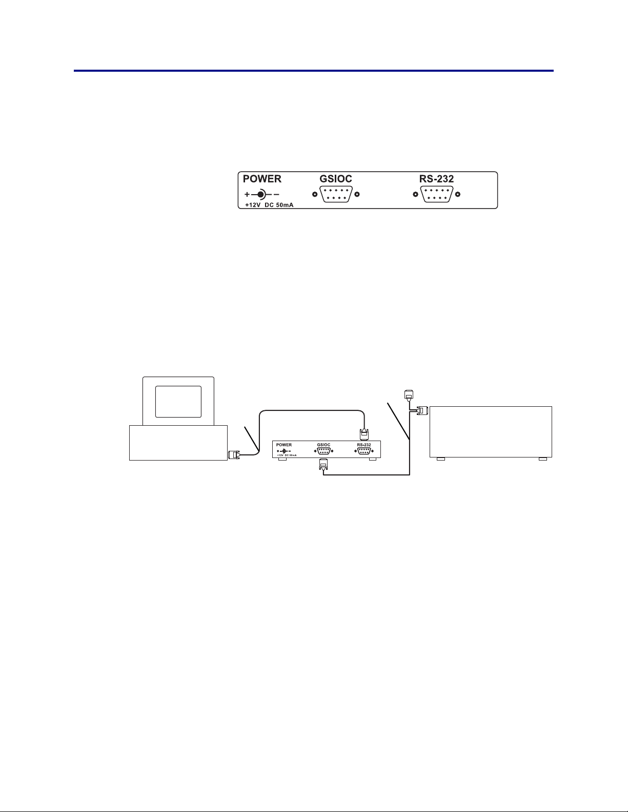
508 Interface Module Rear Panel
RS-232
Locate the RS-232 cable provided with the interface module.
Attach the male end of the RS-232 cable to the 508 RS-232 input. Tighten the
retaining screws.
Connect the female end of the RS-232 cable to the computer’s RS-232 serial
communications port. Again tighten the retaining screws.
computer
GSIOC cable
RS-232
cable
508
Interface Module
Gilson instrument
GSIOC
Use a GSIOC cable to connect the interface module to the Gilson instrument you
wish to control. A GSIOC cable has two 9-pin female connectors and one male
connector.
2-2 Gilson 508 Interface Module User’s Guide
Page 13

Installation
2
Refer to the diagram below to connect the 508 to another Gilson instrument
using a GSIOC cable.
9-pin female
9-pin female
connector;
connect to
GSIOC port of
GSIOC device
9-pin male connector;
connect to another
GSIOC cable for linking
additional GSIOC devices
With additional GSIOC cables, you can connect as many as 32 devices. To connect
additional GSIOC cables, connect the male connector to the next cable’s female
connector (use the female connector that’s not joined to the male connector).
Then connect the remaining female connector to the GSIOC port of the device.
Cables should be arranged in a linear fashion. Any “Y-branching” from the main
GSIOC cable may increase noise.
connector; connect
to the GSIOC port
on the interface
module
Electrical Connections
Power
After you’ve made all the necessary connections, attach the power connector to
the POWER input of the interface module and the transformer to a wall outlet.
Since the interface module is designed to be left on at all times, it does not have
a power switch. If you prefer to have a power switch, a switched power outlet
strip is recommended.
The Power light indicates that power is being supplied to the unit.
Euro plug adapter
Locate the Euro Plug Adapter (part number 594505121) supplied with the 508
Interface Module. If necessary, attach to the power cord to connect the interface
module to an AC power source.
Gilson 508 Interface Module User’s Guide 2-3
Page 14

Operation 3
The 508 Interface Module provides RS-232-to-GSIOC interface from the computer.
Gilson control software packages let you issue GSIOC commands that communicate with any GSIOC
device connected to the interface module.
Gilson 508 Interface Module User’s Guide 3-1
Page 15

Operation
3
Status Lights
The status lights on the 508 Interface Module are useful for verifying operation.
Status Lights
If the Power light is off, power is not being sent to the interface module.
If the RS-232 light is flashing, the 508 Interface Module is responding to the
RS-232 input.
If the GSIOC light is flashing, the 508 Interface Module is receiving a response
from a GSIOC device.
3-2 Gilson 508 Interface Module User’s Guide
Page 16

Maintenance 4
The 508 Interface Module should not require maintenance. The best precautions for continued
operation are to avoid spilling liquids on the connectors and to avoid mechanical strain on the wire
connections.
Gilson 508 Interface Module User’s Guide 4-1
Page 17

Troubleshooting 5
When using the 508 Interface Module with Gilson-supplied accessories, computers and application
software, troubleshooting is simple. Most problems are due to improper connections and installation.
Gilson 508 Interface Module User’s Guide 5-1
Page 18

Troubleshooting
Troubleshooting Chart
5
Troubleshooting Chart
No response to RS-232 input
• There is no DC power connection at power input. If the Power light is off,
check that transformer is plugged into an outlet.
• RS-232 connections are not correct. Check for proper cable and connectors.
• Check RS-232 port of computer for proper operation with other RS-232
devices.
GSIOC devices do not respond to commands
• Check GSIOC cable connections.
• Check GSIOC device unit ID numbers and baud rate settings (must be 19200
or External).
5-2 Gilson 508 Interface Module User’s Guide
Page 19

Troubleshooting
Repair and Return Policies
Before Calling Us
Gilson-authorized representatives will be able to serve you more efficiently if you
have the following information:
• the serial number and model number of the instruments involved. The serial
number is located on the bottom of the unit.
• the installation procedure you used
• list of concise symptoms
• list of operating procedures and conditions you were using when the
problem arose
• list of other devices connected to the interface module and a description of
those connections
5
Repair and Return Policies
• list of other electrical connections in the room
Warranty Repair
Units covered under warranty will be repaired and returned to you at no charge.
If you have any questions about applicability, please contact your local
distributor.
Non-Warranty Repair
For out-of-warranty repairs, contact your local distributor. A Customer Service
representative will discuss service options with you and can assist in making
arrangements to return the equipment, if necessary.
Rebuilt Exchange
For some units, rebuilt exchange components are available. Contact your local
distributor for details.
Gilson 508 Interface Module User’s Guide 5-3
Page 20

Troubleshooting
Repair and Return Policies
5
Return Procedure
Contact your local distributor’s Customer Service Department to obtain
authorization before returning any Gilson equipment. To return a piece of
equipment:
• Carefully pack the unit to prevent damage in transit. Check with your
distributor regarding proper method of shipment. No responsibility is
assumed by Gilson or your distributor for damage caused by improperly
packaged instruments. Indicate the authorization on the carton and on the
packing slip.
• Always insure for the replacement value of the unit.
• Include a description of symptoms, your name, address, phone number, and
purchase order to cover repair costs, return and shipping charges, if your
institution requires it.
Unit End-of-Life
When a unit reaches the end of its useful life, refer to www.gilson.com
for directions and information on the end-of-life policy. This is in
accordance with the European Union Directive 2002/96/EC on Waste
Electrical and Electronic Equipment (WEEE).
5-4 Gilson 508 Interface Module User’s Guide
 Loading...