

Page 1

402 Dilutor Dispenser
User’s Guide
Page 2

Page 3

402 Dilutor Dispenser
User’s Guide
LT801310/C - ©2003 Gilson SAS All rights reserved November 2003
Page 4

Page 5

Contents
Table of Contents 0
Safety
1 Introduction
Notational Conventions .................................................................. 1-2
Overview .......................................................................................... 1-3
Unpacking ...................................................................................... 1-5
Warranty ......................................................................................... 1-6
Customer Service .......................................................................... 1-7
2 Description
Single-Syringe Model ....................................................................... 2-2
Front Panel ................................................................................ 2-2
Rear Panel ................................................................................. 2-2
Dual-Syringe Model ...................................................................... 2-3
Front Panel ................................................................................ 2-3
Rear Panel ................................................................................. 2-3
Keypad and Probe ......................................................................... 2-4
Keypad ...................................................................................... 2-4
Probe .......................................................................................... 2-4
Hydraulic Components ............................................................... 2-5
Valve .......................................................................................... 2-5
Tee-junction .............................................................................. 2-5
Syringes ..................................................................................... 2-5
3 Installation
Assembling the Probe ...................................................................... 3-2
For Standard Use ........................................................................ 3-2
Adapter Kit for Disposable Tips ................................................ 3-2
Connecting the Tubing .................................................................... 3-4
Single-Syringe Model ................................................................. 3-4
Dual-Syringe Model ................................................................ 3-5
Electrical Connections.................................................................. 3-7
Sector Block ............................................................................... 3-7
Voltage Selector........................................................................ 3-7
Installing the Fuses ................................................................. 3-7
Connecting the Power Cord .................................................. 3-8
Connecting the Keypad.......................................................... 3-8
Connecting the Probe .............................................................. 3-8
Syringes........................................................................................... 3-9
Assembling a Syringe ............................................................. 3-9
Fitting a Syringe ....................................................................... 3-9
Table of Contents-1
Page 6

Upgrading to Dual-Syringe Model ........................................... 3-10
Removing the Cover .............................................................3-11
Connecting the Flat Cable.................................................... 3-11
Inserting the Module ............................................................ 3-11
4 Operation - Standard Use
Essential Steps .................................................................................. 4-2
Standard Parts.......................................................................... 4-2
Connect the Keypad ................................................................ 4-2
Fit the Fuses and Connect the Power ................................... 4-2
Assemble and Connect the Probe ......................................... 4-2
Connect the Tubing ................................................................. 4-2
Switch-on .................................................................................. 4-3
Configuration (Conf) .............................................................. 4-4
Fit the Syringe(s) ...................................................................... 4-7
Creating a Method (Edit) ....................................................... 4-7
Prime the 402 (Man) .............................................................. 4-10
Running a Method (Run) ..................................................... 4-11
5 Operation - Advanced Use
Correct Use of the 402 ................................................................... 5-2
Single-Syringe Model .............................................................. 5-2
Dual-Syringe Model ................................................................ 5-2
Software .......................................................................................... 5-5
Entering the Configuration (Conf)........................................ 5-6
Creating a Method (Edit) ....................................................... 5-9
Saving a Method.................................................................... 5-10
File Manipulations (File) ...................................................... 5-10
Direct Manipulations (Man) ............................................... 5-12
Tasks - Detailed Descriptions .............................................. 5-15
Additional Information ............................................................. 5-31
Flow Rates............................................................................... 5-31
Syringe Correction Function................................................ 5-33
Use of Disposable Tips .........................................................5-33
6 Maintenance
Table of Contents-2
Cleaning ......................................................................................... 6-2
Cleaning the Exterior .............................................................. 6-2
Cleaning the Valve.................................................................. 6-2
Cleaning the Tee Junction ...................................................... 6-3
Cleaning the Syringe Assembly ............................................ 6-4
Autoclaving.................................................................................... 6-5
Autoclaving the Tubing ......................................................... 6-5
Changing the Syringe Piston Assembly.................................... 6-6
Replacing the Piston ............................................................... 6-6
Page 7

7 Troubleshooting
Appendices
Changing the Piston Syringes and Piston Noses .................... 6-7
Changing the 100 and 250 µL Piston Noses ...................... 6-7
Changing the 500 µL Piston Noses ......................................6-9
Changing the 1 mL Piston Noses ....................................... 6-10
Changing the 25 mL Piston Noses ..................................... 6-11
Changing the 5 mL and 10 mL Piston Noses................... 6-11
Mechanical Problems ................................................................... 7-2
Hydraulic Problems ...................................................................... 7-3
Electrical Problems ........................................................................ 7-4
A - Parts and Accessories Lists ....................................... Appendix A-1
402 Single Syringe ............................................... Appendix A-2
402 Dual Syringe with Tee Junction Config. ...Appendix A-3
Additional Accessories....................................... Appendix A-4
Spare Parts ............................................................ Appendix A-5
B - Chemical Compatibility ..................................... Appendix B-2
Materials in Contact with Liquids ................... Appendix B-2
Compatibility ....................................................... Appendix B-2
C - Technical Data ..................................................... Appendix C-1
Hydraulics ............................................................Appendix C-2
Mechanics............................................................. Appendix C-5
Environmental .....................................................Appendix C-6
D - Error Messages ................................................... Appendix D-2
Index
Table of Contents-3
Page 8

Page 9

Safety 0
Safety
Read this section carefully before installing and operating the instrument.
For safe and correct use of the instrument, it is essential that both operating and
service personnel follow generally accepted safety procedures as well as the safety
instructions given in this document, the 402 Dilutor-Dispenser User’s Guide.
The instrument described in this document is a syringe operated pump for transferring liquids. It should only be used in the laboratory or similar indoor environment for
analytical purposes, by qualified personnel. If an instrument is used in a manner not
specified by Gilson, the protection provided by the instrument may be impaired.
Voltages present inside the instrument are potentially dangerous. If there is a problem
with the instrument, the power cable should be removed until qualified service personnel
have repaired it. This is to prevent anyone from inadvertently using the instrument,
thus causing possible harm to themselves, or damage to the instrument itself.
The leakage current of this instrument is within the limits allowed by international
safety standards for laboratory equipment. An efficient ground connection is imperative for the physical protection of the user.
Power supply cord reference 7080316106 is for use in France and Germany. Power
supply cord reference 7080316105 is for use in USA and Canada. For other countries
contact your local Gilson distributor. You must only use the type of fuse described in
this document: 1.0 Amp type “T” slow blow.
Adequate protection including clothing and ventilation must be provided if dangerous
liquids are used in the analytical work. In case of incidental spillage, carefully wipe with a
dry cloth, taking into account the nature of the spilled liquid and the necessary safety
precautions.
Cleaning, dismantling, maintenance, and repair should only be performed by personnel
trained in such work, and who are aware of the possible dangers involved.
Safety-1
Page 10
Safety
!
1
Individual components:
parts of the valve, the Tee
junction, and the syringes
(except for the 25 mL syringe)
may be autoclaved after
dismounting (121°C, 0.1 MPa,
20 min).
Symbol Explanation
Alternating current
~
PROTECTIVE CONDUCTOR
TERMINAL
On (Supply switch)
I
Off (Supply switch)
O
This instrument1 must not be sterilized, using an
autoclave, or any other mechanical device. When
you need to clean an instrument, use one of the
three following methods:
1 - a clean dry cloth,
2 - a cloth dampened with water,
3 - a cloth dampened with soapy water.
If a cloth dampened with soapy water is used to clean
the instrument, only domestic soap may be used.
No other form of detergent or chemical may be
used.
These electronic and hazard symbols
appear on the 402 Dilutor Dispenser:
Caution, risk of electric shock
Caution (refer to User’s Guide)
Safety-2
Page 11

Introduction 1
The following chapter describes the instrument, the service and warranty conditions.
1-1
Page 12

Introduction 1
Notational Conventions
The conventions in this User’s Guide are as follows.
Used in the stand-alone mode, this instrument is
referred to as ‘402 Dilutor-Dispenser’ or simply 402.
Specific keys to press on the Gilson Keypad are
represented in bold capitals, for example: ‘key in
the value and press ENTER’; where ENTER is a
Notational Conventions
key on the keypad.
For a soft-key that must be pressed, the function of
that key is represented in bold, for example: ‘Press
Prime to prime the pump’.
The Gilson Keypad displays on-screen messages as
normal typeface inside a frame.
1-2
Page 13

Introduction 1
Overview
The 402 Dilutor-Dispenser, is used to transfer liquids
between vials according to user defined protocols
(Methods). You program the 402 Dilutor-Dispenser
via the keypad, which includes an LCD screen, for
communication purposes.
You may store a total of 99 linkable Methods using
the keypad. Each Method consists of one or more of
the following tasks: Dilute, Dispense, Mix, Pipette,
and Rinse. In addition three functions for direct
manipulation are available: Priming, Titration,
Volume Measurement.
Gilson’s 402 Dilutor-Dispenser is available in two
configurations: Single-syringe, or Dual-syringe.
The 402 Dilutor-Dispenser is very versatile; it may
be fitted with seven sizes of syringe. The standard
402 Dilutor-Dispenser is equipped with a handheld probe for aspirating and dispensing liquids.
Optionally, the probe may be fitted with disposable
tips (Gilson Diamond® Tips, D200 and D1000).
Overview
This versatility means that your 402 Dilutor-Dispenser
may be used for a wide variety of applications
including the chemical field where the ability to
handle large volumes or high dilution ratios may be
appreciated, and the biological field where small
volumes and protection against cross-contamination
are important (see Autoclavability, page 6-5).
It can even be used with corrosive liquids (see
Chemical Compatibility, Appendix B).
Refer to Appendix A for lists of the standard
equipment, additional accessories and spare parts.
The 402 DD is supplied with a tubing kit for connecting to a solvent reservoir. Syringes are not
included in the standard equipment; you should
order syringe(s) appropriate to your Method (volume,
systematic error and flow rate requirements; refer to
Appendix C). Also, a Tee junction kit (not including the syringe) is available for upgrading a Singlesyringe Dilutor-Dispenser to the Dual-syringe version.
1-3
Page 14

Introduction 1
Good Laboratory Practice (GLP) is facilitated by the
following:
Overview
씮 codes to protect the program files against unau-
thorized modification,
씮 counters for the number of syringe and valve
operating-cycles,
씮 checking protocol for the hydraulic specifica-
tions (IQ/OQ procedures),
씮 correction of the syringe-piston stroke to com-
pensate for environmental factors (temperature,
viscosity, etc.).
1-4
Page 15

Introduction 1
Unpacking
Your 402 Dilutor-Dispenser is shipped in a box
together with its various accessories. The original
box and packing material should be kept in case
the equipment has to be returned to your Gilson
distributor.
You should check off the parts received in the box
against the parts list (refer to Appendix A), at the
time that you receive the shipment, even if the 402
is not to be used immediately. Your Gilson distributor should be notified immediately of any inconsistencies between the contents of the box and the
parts list, or if any of the parts appear to have been
damaged in transit.
Unpacking
1-5
Page 16

Introduction 1
Warranty
Warranty
If the 402 Dilutor-Dispenser does not appear to
function correctly, first verify the electrical connections are correct and that the instrument is
switched ON. Contact your Gilson distributor for
technical advice or possibly a service visit. Any
service required will be given within the warranty
conditions assured by your Gilson distributor.
1-6
Page 17

Introduction 1
Customer Service
Gilson and its worldwide network of authorized
distributors provide you with four types of assistance: sales, technical, applications and service.
Customer Service personnel are able to serve you more
efficiently if you provide the following information:
• The serial number and model number of the
equipment involved.
• The installation procedure you used.
• A concise list of the symptoms.
• A list of operating procedures and conditions you
were using when the problem arose.
• A list of other devices connected to the system (if
any) and a system diagram showing the connections.
Customer Service
• A list of other electrical connections in the room.
1-7
Page 18

Introduction 1
1-8
Page 19

Description 2
The following chapter describes the mechanics and hydraulics of the Dilutor-Dispenser.
Two models of 402 Dilutor-Dispenser are available: Single-syringe and Dual-syringe.
Each model comes with a keypad, a probe, and accessories. You order and fit the
syringe(s), from those described on page 2-6, most suited to your application.
Your 402 is delivered with the appropriate modules fitted. If later, you decide to
convert a Single-syringe model into a Dual-syringe model, you must order and fit a
Tee-junction module to the right-hand side of your dilutor; the left-hand always
contains a Valve module.
2-1
Page 20
Description 2
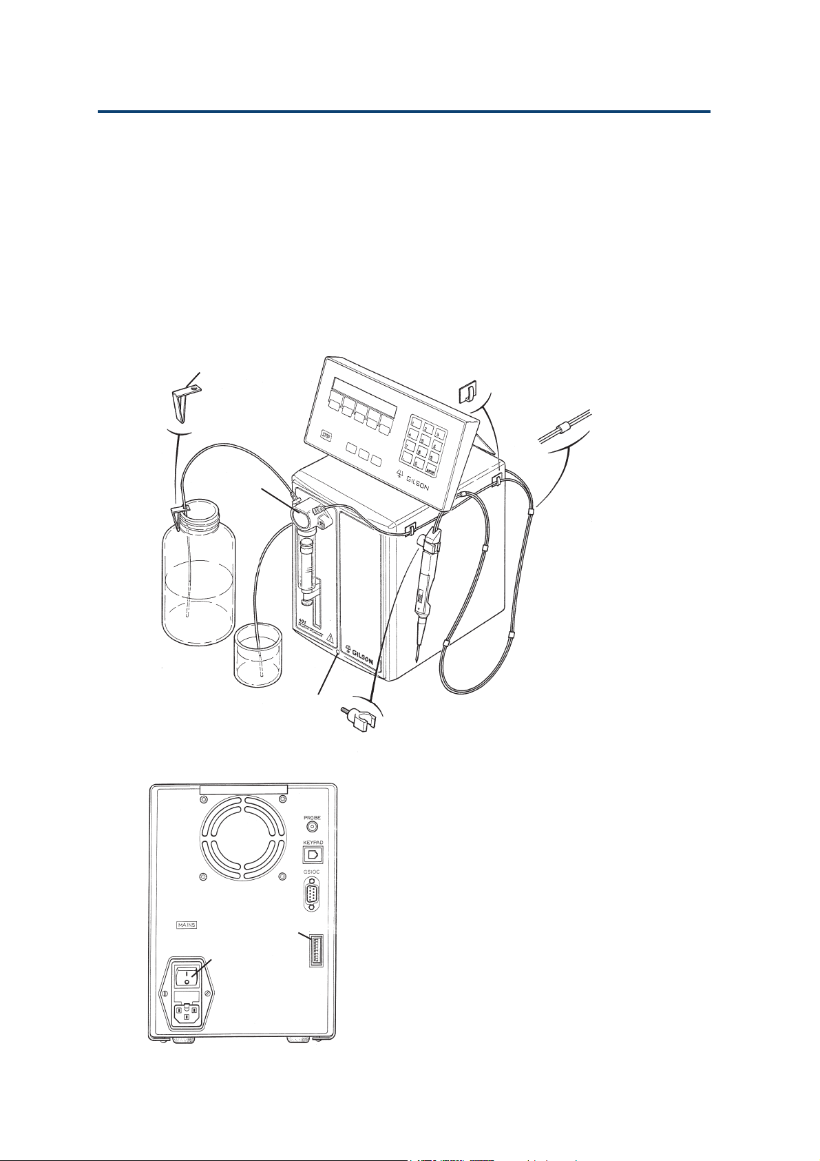
Single-syringe Model
The Single-syringe model has a Valve module at the
left, and a blanking plate at the right.
The Valve module includes one motor to operate
the syringe and another motor to switch the valve.
It is a liquid transfer station that can be used to
Single-syringe Model
deliver up to 25 mL in one stroke, and down to 1 µL
(typical value), with high accuracy.
Bottle Clip for Tubing
Valve Module
ON/OFF indicator
Tubing Clip (Self-adhesive)
Cable Support
Clamp for Probe
2-2
Microswitches
ON/OFF Switch
Front Panel
The front panel holds the hydraulic components
and is fitted with an ON/OFF indicator.
Rear Panel
The rear panel holds a socket for connecting the
keypad, a connector for the probe, the ON/OFF
switch, and voltage selector/fuse holder. There is
also a Gilson Serial Input Output Channel (GSIOC)
connector, which is a communications channel to
link the 402 Dilutor-Dispenser with other equipment,
if required. There is also a bank of microswitches
for use in setting up the communications channel.
Page 21
Description 2
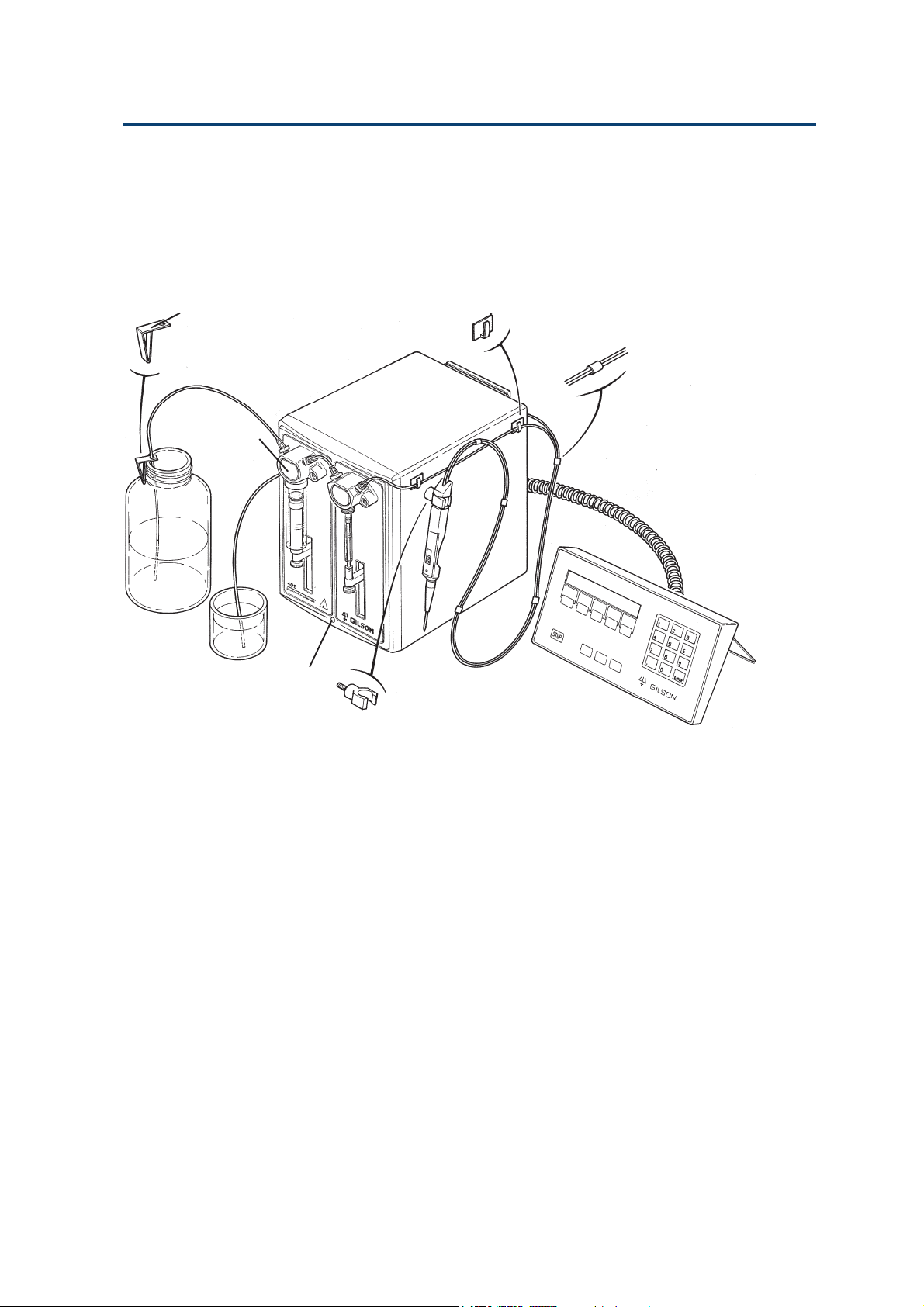
Dual-syringe Model
The Dual-syringe model is fitted with a Valve
module at the left and a Tee-junction module at the
right. The modules are linked by plastic tubing.
Dual-syringe Model
Bottle Clip for Tubing
Valve Module
ON/OFF indicator
Front Panel
Tubing Clip (Self-adhesive)
Cable Support
Clamp for Probe
The front panel holds the hydraulic components
and is fitted with an ON/OFF indicator.
The Valve module includes one motor to operate the
syringe and another motor to switch the valve. The
Tee-junction module has only one motor, to operate
the syringe.
The Dual-syringe model may be fitted with syringes
of different volumes. The left syringe is the large
volume syringe and is used to deliver a large volume
of liquid in a minimum time. The right syringe can
be used to transfer smaller volumes with high
reproducibility and accuracy (refer to Appendix C
for Technical Data). The benefits of this configuration
are a large dilution ratio with the best reproducibility and fast transfer times.
Rear Panel
This is the same for both models.
2-3
Page 22
Description 2
Keypad and Probe
Keypad
The keypad includes an LCD display (two 24character lines), membrane touch-keys, and a
connecting cord.
Keypad and Probe
Numeric keys: the keypad has the numbers 0 to 9, a
decimal point key, and the Enter key.
Five Soft-keys: the function of each key depends on
the screen that is displayed (e.g. Next,
Prev, Chge...).
STOP key: Press this key to stop the current ac-
tion (Method or direct manipulation).
HELP key: Press this key to access help messages
relating to the current screen.
ESC key: Press this to quit a menu or return
to the first menu of the software
branch.
CLEAR key: Press this key to cancel a value and
return to the previous value before
validating it.
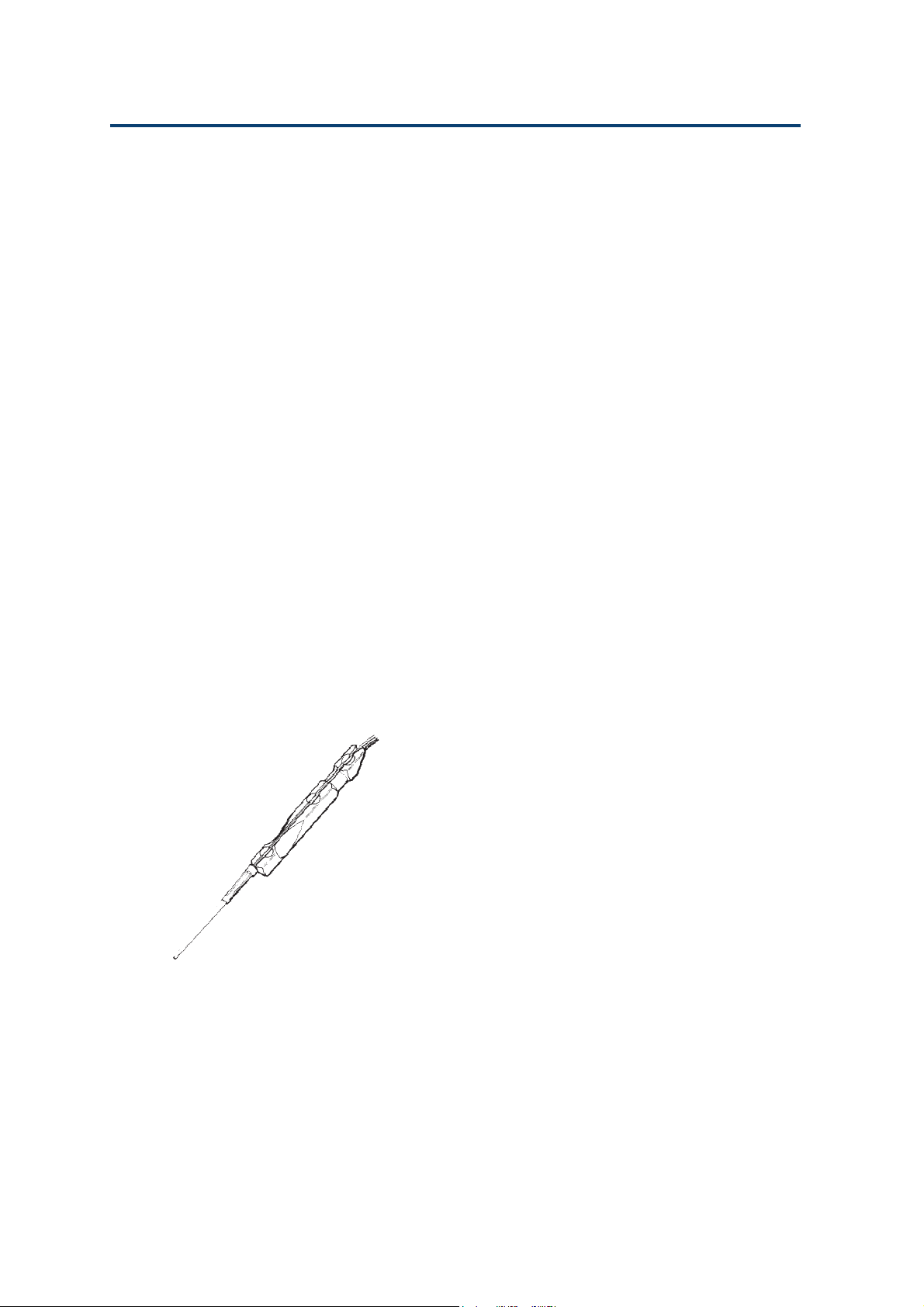
Probe
The assembled probe fitted with the standard probe
nozzle is shown opposite. Assembly and installation
of the standard probe is described in Chapter 3.
A kit is available to enable you to fit Gilson’s
Diamond® tips (D200, D1000) to the probe (see
Chapter 3).
2-4
Page 23
Description 2
Hydraulic Components
Valve
Hydraulic Components
The two-position valve, which is fitted to the lefthand side of the 402, has three ports. It switches
the syringe port to either the reservoir or to the
probe side (see opposite figure).
The valve, which has a 0.5 sec rotation period, is
driven by a stepper motor. It is designed to withstand a million rotations, when used with water.
The liquid contact surfaces of the valve, which is
autoclavable, are in PEEK and ceramic (121°C,
0.1 MPa, 20 min).
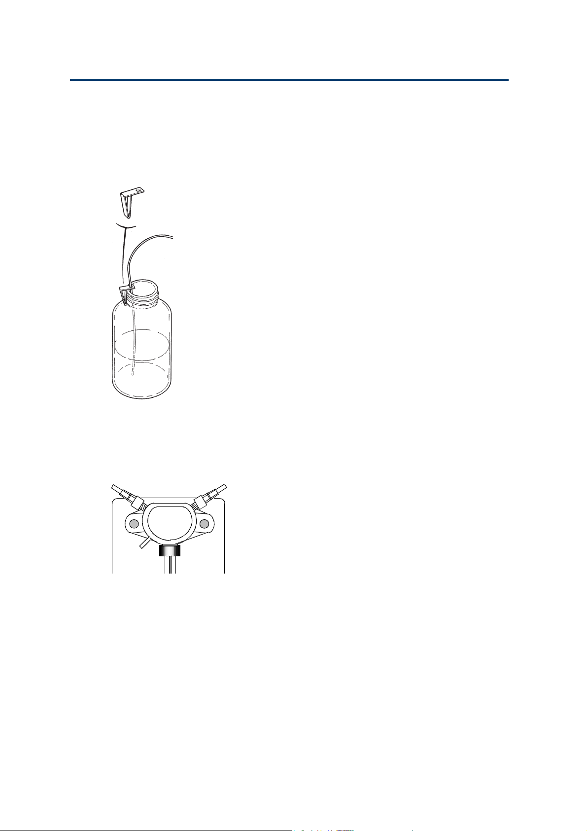
Tee Junction
The Tee-junction, which is fitted to the right-hand
side of the dual-syringe model, has three ports: the
inlet from the valve, the outlet to the probe, and the
syringe port (see opposite figure).
The Tee-junction, which has no internal moving
parts, includes 2 channels, each 1.5 mm in diameter oriented at 120°. The liquid contact surfaces of
the Tee-junction, which is autoclavable, are in PEEK.
From reservoir
To waste
From Valve
Probe (or Tee
junction)
Syringe
To Probe
Syringe
Syringes
The choice of syringe allows the 402 Dilutor-Dispenser
to handle volumes from 1 µL to 25 mL with low
values of systematic and random error. The 402
Dilutor-Dispenser is able to transfer liquid as
follows:
- from 1 µL to 10 mL from the probe (transfer
tubing volume of up to 10 mL),
- up to 25 mL from the reservoir, in one stroke,
- up to 99 mL from the reservoir, in several strokes.
When using the Dual-syringe model, a theoretical
dilution ratio of 1/25000 is achieved in one stroke
of both sample and diluent syringes. However, you
are advised not exceed a ratio of 1/500 for any
given dilution, in order to stay within the RSD
range (after efficient mixing).
2-5
Page 24
Description 2
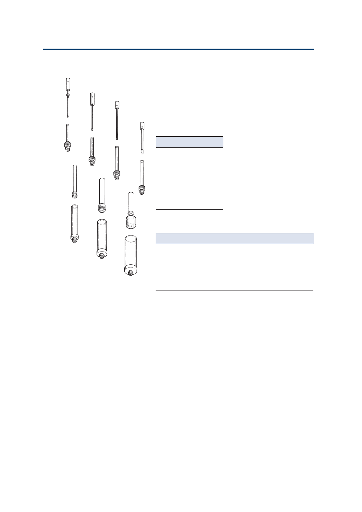
0.1 mL
0.25 mL
0.5 mL
Hydraulic Components
5 mL
10 mL
1 mL
25 mL
There are seven syringe sizes available for the 402,
all except the 25 mL are autoclavable. The lifetime
of all pistons (see Chapter 6), when they are used
with water at a pressure of up to 0.3 MPa is over
30000 cycles (each cycle contains 2 strokes: one up
and one down).
The available syringe sizes are:
Part Number Description
25025341 0.1 mL
25025342 0.25 mL
25025347 0.5 mL
25025343 1 mL
25025344 5 mL
25025345 10 mL
25025346 25 mL
Syringe Materials
Part of the syringe Material
Syringe body Borosilicate glass
Syringe adapter 316L stainless steel
Piston Stainless steel (models up to 1 mL)
Aluminum
Piston nose PTFE/Ekonol (PTFE for the 25 mL)
2-6
Page 25

Installation 3
This chapter explains how to install the fuses, syringes and hydraulics according to
your system requirements.
This chapter explains how to add the extra module to upgrade your 402 to a dual
syringe pump.
3-1
Page 26
Installation 3
Assembling the Probe
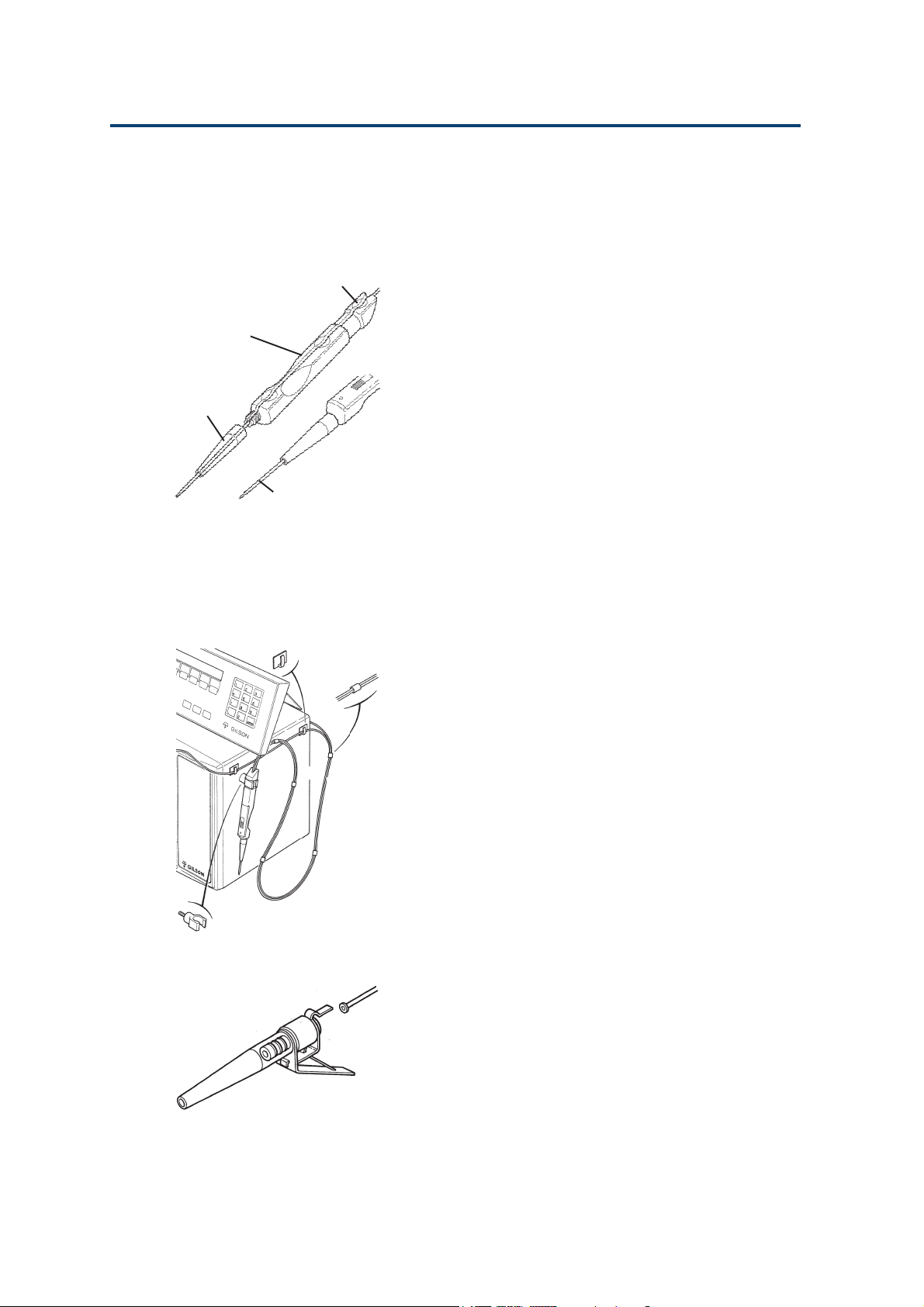
For Standard Use
Access Point
Probe
Assembling the Probe
Probe
Nozzle
Transfer Tubing
When you want to increase the
length of tubing protruding
from the probe, you must first
carefully lift the tubing out of
the handle, otherwise you will
damage the tubing.
In standard use the probe is used with the 2 mL
tapered transfer-tubing (see opposite figure).
1. Thread the tapered end of the transfer-tubing
through the plastic ‘tunnels’ in each of the 5 premounted cable supports (see figure below).
2. Lay the tubing on the probe’s groove such that
about 4 cm of the tapered end protrudes from
the end of the probe.
3. Push the tubing into the groove in the probe at
the 3 round access points using (for example)
the rounded end of a pencil. Do not press on the
tubing with your fingernail.
4. Push the tapered end of the tubing through the
standard tip, then screw the tip onto the end of
the probe.
5. Plug the end of the control cable into the socket,
labeled ‘PROBE’ at the back of the 402.
6. Fit the clamp for probe at the right-hand side of
the 402 (see opposite figure).
7. Mount the probe on the clamp.
8. Connect the other end of the tubing to the outlet
of the Valve (Single-syringe) or the Tee-junction
(Dual-syringe).
9. Use the 402 Software to check (and change, if
necessary) the configuration using the Conf
(Vol) menu.
Adapter Kit for Disposable Tips
The ability to use Diamond Tips will extend the use
of your 402 into the biological field, where protection against cross-contamination is important, and
in the chemical field to protect the tubing from
corrosive liquids.
You must fit a tip-holder to the probe when you
want to use Gilson’s Diamond tips. An adapter kit
(reference F4015015) is available to permit you to
fit them to the probe. The kit includes two sizes of
tip-holder (with built-in tip ejector), and a special
non-tapered 2 mL transfer tubing, as follows.
3-2
Page 27

Installation 3
2 Special adapters for the probe
1 D200 tips, pack of 10
1 D1000 tips, pack of 10
1 Transfer-tubing (outlet) non-tapered, FEP (2 mL)
1. Lay the tubing on the probe’s groove such that
the end with the small washer is just at the
orifice of the probe.
2. Push the tubing into the groove in the probe at
the 3 round access points using the rounded end
of a pencil (for example). Do not press on the
tubing with your fingernail.
3. Screw the tip-holder onto the end of the probe.
4. Plug the end of the control cable into the socket,
labeled ‘PROBE’ at the back of the 402.
5. Fit the clamp at the right-hand side of the 402
(see on the previous page).
6. Mount the probe on the clamp.
7. Connect the other end of the tubing to the outlet
of the valve (Single-syringe) or the Tee junction
(Dual-syringe).
(1) The small washer is important
in that it helps to ensure that
fluid does not leak from the
junction between the tip-holder
and the orifice of the probe.
(2) The special ‘S’ shaped metallic
clips, which are pre-mounted, are
for supporting the tubing on the
black control cable. The tubing
for use with the tip-holder will
not pass through the plastic
‘tunnels’ in the pre-mounted
cable supports. However, to
make the metallic clip easier to
attach, you can push these black
tubing-supports to the end of
the cable.
Assembling the Probe
8. Inform the 402 Software of the new configuration using the Conf (Vol) menu.
9. Fit a tip to the holder. In use, when you change
a tip, wipe the end of the tip-holder first, to
remove any liquid from the orifice. Do not
twist the probe to the left, when fitting a tip,
otherwise the tip-holder will unscrew itself.
3-3
Page 28
Installation 3
Connecting the T ubing
Tubing connectors should be hand-tightened,
tools should not be used as their use will damage
the connector’s thread.
Single-syringe Model
Connecting the T ubing
From
reservoir
Transfer tubing
to probe
Valve Inlet Tubing
A length of Fluoride Ethylene Propylene (FEP)
tubing, supplied with the 402, is used to connect
the inlet port to the solvent reservoir. Screw the
connector into the inlet port (left-hand) of the valve
and put the other end into the reservoir. A bottle
clip is provided to hold the tubing securely in the
reservoir (see opposite Figure).
An alternative tubing, fitted with a connector at
one end and a 20 µm filter at the other, is available
as an accessory (reference 3645357).
Waste Tubing
Connect a suitable length of tubing from the waste
outlet of the valve to a suitable receptacle. The valve
releases liquid through the waste outlet if the pressure
inside the valve is too high. For the pressure limits
of the valve, refer to Appendix C, Technical Data.
Transfer Tubing (Probe)
3-4
To waste
V alve
This tubing (FEP) allows the transfer of samples
aspirated from the probe and prevents the contamination of the syringe(s). The size of transfer tubing
is chosen as a function of the volumes of samples,
reagents, and air gaps that have to be handled via
the probe. The total volume transferred must be less
than the volume of the transfer tubing.
The transfer tubing connects the outlet port (righthand) of the valve to the probe. A 2 mL tapered
tubing is supplied as standard; 1 mL, 5 mL, and
10 mL are available as additional accessories.
Self-adhesive clips are provided for holding the
transfer tubing securely against the side of the 402.
The 1 mL transfer tubing is recommended for transferring volumes smaller than 1 mL. To avoid movements of the tubing that could affect the precision,
the 5 mL and 10 mL transfer tubings are rolled and
held by magnets on the left-side of the 402.
Page 29
Installation 3
After assembling the probe, the other end of the
tubing is installed by screwing the connector into
the right-hand port of the valve. When you use
Gilson Diamond Tips, the special non-tapered
tubing, included in the kit, must be fitted.
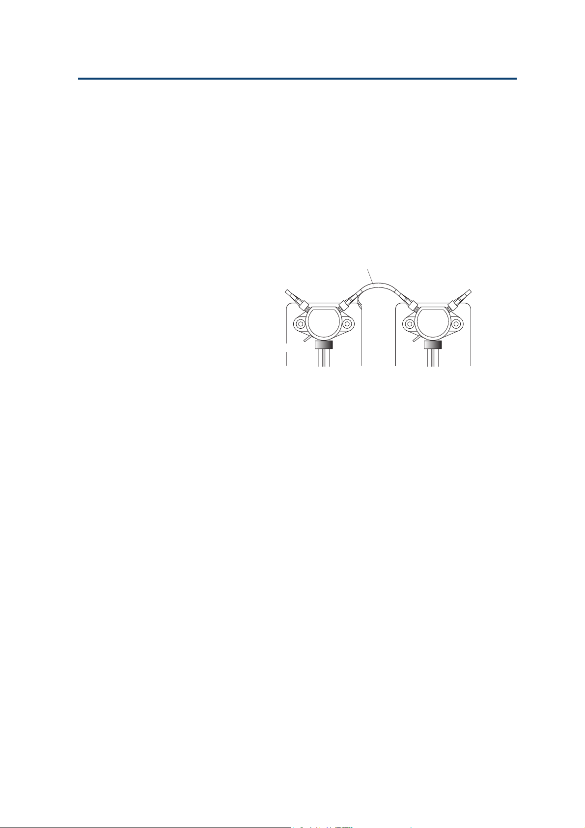
Dual-syringe Model
Valve Inlet Tubing
A length of Fluoride Ethylene Propylene (FEP) tubing, supplied with the
402, is used to connect the inlet port
to the solvent reservoir. Screw the
connector into the inlet port (lefthand) of the valve and put the other
end into the reservoir. A bottle clip is
provided to hold the tubing securely
in the reservoir.
An alternative tubing, fitted with a
connector at one end and a 20 µm
filter at the other, is available as an
accessory (reference 3645357).
From
reservoir
To waste
Connection tubing
Transfer tubing
to probe
Left
Syringe
V alve Tee-junction
Right
Syringe
Connecting the T ubing
Valve Waste Tubing
Connect the length of tubing (supplied as standard)
to the waste outlet of the valve, and put the other
end into the waste or any other suitable receptacle.
The valve releases liquid through the waste outlet,
if the pressure inside the valve is too high (see
Appendix C, Technical Data).
Connection Tubing (Valve to Tee-junction)
This tubing has connectors at both ends and is used
to connect from the valve outlet port (right-hand) to
the Tee-junction inlet port (left-hand). It is made of
FEP and has the following dimensions: 70 x 3 x 2 mm.
It is autoclavable (20 min. at 0.1 MPa, 121 °C).
Transfer Tubing (Probe)
This tubing (FEP) allows the transfer of samples
aspirated from the probe and prevents the contamination of the syringe(s). The size of transfer tubing
is chosen as a function of the volumes of samples,
reagents, and air gaps that have to be handled via
the probe. The total volume transferred must be
less than the volume of the transfer tubing.
3-5
Page 30

Installation 3
The transfer tubing connects the outlet port (righthand) of the Tee-junction to the probe. A 2 mL
tapered transfer-tubing is supplied as standard ;
1 mL, 5 mL, and 10 mL are available as additional
accessories.
Self-adhesive clips are provided for holding the
transfer tubing securely against the side of the 402
(see previous page).
Connecting the T ubing
The 1 mL transfer tubing is recommended for
transferring volumes smaller than 1 mL. To avoid
movements of the tubing that could affect the
precision, the 5 mL and 10 mL transfer tubings are
rolled and held by magnets on the left-side of the
402.
After assembling the probe, the other end of the
tubing is installed by screwing the connector into
the right-hand port of the Tee-junction. When you
use Diamond tips, the special non-tapered tubing,
included in the kit, must be fitted.
3-6
Page 31

Installation 3
Electrical Connections
The rear panel of the 402 Dilutor-Dispenser houses:
- sector block containing the power socket, fuse
drawer and ON/OFF switch,
- keypad connector,
- probe connector,
- GSIOC connector.
Sector Block
The sector block contains the power socket, fuse
holder and ON/OFF switch. Your 402 can be
connected to a 100-120 VAC or a 220-240 VAC
supply. In either case, two 1A type “T” slow blow
fuses must be installed (reference 6730104006).
Electrical Connections
Voltage Selector
The instrument has no physical voltage selector.
The 402 Dilutor-Dispenser can be connected to 100
or 240 V. Power control is carried out electronically
on the power supply board.
Installing the Fuses
For safety reasons, your 402 is delivered without
the fuses installed. You must install two 1A type
“T” slow blow fuses (reference 6730104006), as
follows:
1) Disconnect the power lead from the instrument.
2) Use a small screwdriver to pry open the fuse
holder drawer.
3) Pull the drawer gently towards you, to open the
fuse receptacle.
4) Push the fuses into position.
5) Push the fuse holder back into the sector block.
ON/OFF switch
Fuse holder
In the figure, the drawer containing the fuses is
shown separated from the sector block. In fact the
drawer hinges downwards; it is not advisable, nor
necessary, to remove it completely from the block.
3-7
Page 32

Installation 3
Connecting the Power Cord
Make sure that the ON/OFF switch is in the OFF
(down) position. Connect the power cord to the
power socket at the rear of the instrument and then
to the power supply source. When the ON/OFF
switch is put to the ON position, the instrument
initializes; the valve motor rotates the spindle and
stops with the valve set to the outlet position. The
Electrical Connections
piston motor raises the piston to the upper position.
Connecting the Keypad
Switch off the 402 Dilutor-Dispenser, before connecting or disconnecting the keypad.
Grip the connector, at the end of the coiled connection cable, so that you squeeze the clip between
your thumb and index finger. Then, plug the
connector into the socket on the rear panel labeled
‘KEYPAD’ (see figure). You must grip the connector
in the same way when disconnecting the keypad.
The coiled connecting cable enables you to use the
keypad beside the 402 (as in Chapter 2), or even at
some distance away from it. However, you can also
install the keypad on top of the 402; to do this you
should insert the tab on the rear support of the
keypad into the slot on top of the 402 and then
gently push the tab in as far as it will go.
Connecting the Probe
Grip the connector, at the end of the black connection cable, between your thumb and index finger.
Then plug the connector into the socket on the rear
panel labeled ‘PROBE’.
3-8
Page 33

Installation 3
Syringes
Outlet
The 402 Dilutor-Dispenser is supplied without
syringes. Order a syringe (or syringes), appropriate
to your Method, for your 402 Dilutor-Dispenser.
Mount the syringe on the valve or Tee-junction.
Inlet
Valve
Syringes
Assembling a Syringe
The syringe and its piston are supplied assembled.
However, if you remove the syringe from the piston,
ensure that the piston and the piston nose are free
from dust and contamination before reinserting the
piston into the syringe.
Wet the piston nose (with water), insert the piston
nose into the syringe body, and then push the
piston into the syringe.
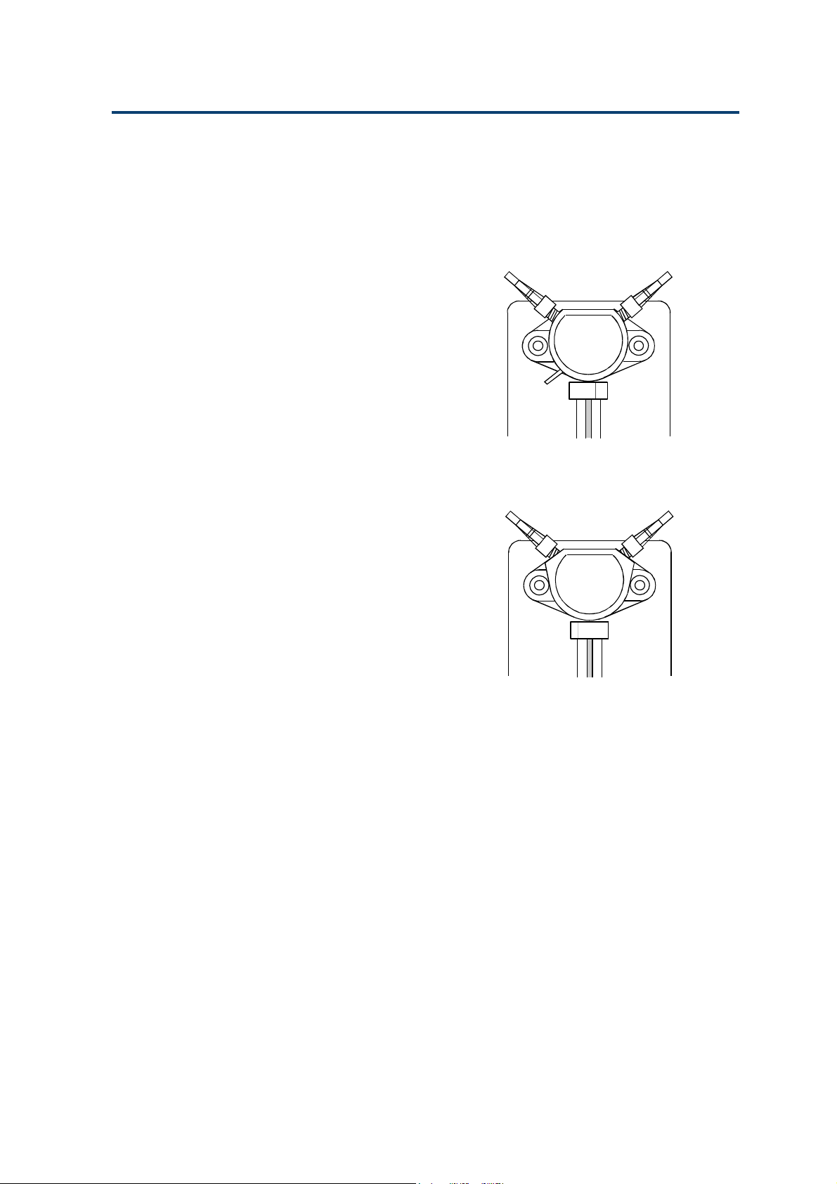
Fitting a Syringe
Before fitting one of the smaller syringes (100 µL,
250 µL, 500 µL and 1 mL), prime it manually by
placing its open end in the solvent reservoir, then
aspirate using the piston. This manual prime is not
necessary for the 5 mL, 10 mL and 25 mL syringes.
You must use the keypad software to lower the
piston operating rod. You should therefore refer to
Chapter 4, which describes the complete procedure
for fitting a syringe. When changing a syringe, you
should first undo the piston securing-screw in order to
free the piston assembly from the piston operating-rod.
Waste
Syringe
Piston
operating rod
Cover
seal
Valve
screw
The 100 µL, 250 µL and 500 µL syringes are supplied with a cover seal to ensure an airtight fit
between the syringe and the valve or Tee. Refer to
the opposite figure for the correct orientation of the
cover seal.
If you change the syringe size, don’t forget to
change the declared syringe volume in your software’s system configuration.
Syringe
body
3-9
Page 34

Installation 3
Upgrading to Dual-syringe Model
The single syringe 402 can be upgraded to improve
the versatility of the system.
To upgrade to the Dual-syringe 402, you must
install a Tee-junction module (kit reference F4015010)
at the right-hand-side of the 402. You must first
install the syringe module (includes motor etc.) and
then fit the Tee-junction.
Before installing the module: make sure that the ON/
OFF switch is in the OFF position, remove the power
Upgrading to Dual-syringe Model
cord, and disconnect any hydraulic connections
from the 402.
3-10
Page 35

Installation 3
Removing the Cover
1) Undo the four screws (with two washers) at the
base of the 402 that secure the top cover. Place
the 402 in the upright position, pull the sides of
the cover outwards, and then lift off the cover.
2) Undo the two nuts inside the front panel (near
the top) that secure the blanking plate, then
remove the blanking plate.
Connecting the Flat Cable
There is a flexible flat cable inside the 402 (attached
to the lower chassis with Velcro) that connects the
logic board to the Valve module. Detach the cable
from the lower chassis, then use the free connector
to connect to the motor drive board on the upgrade
module. With reference to the opposite figure, the
loose-end of the flat cable (with the second connector) and the connecting cable may be re-attached,
using their Velcro strips.
Upgrading to Dual-syringe Model
1. Hold the module upright, in front of the 402
front panel.
2. Thread the flat cable through the aperture for
the module and connect it to the syringe motor
drive board on the Tee module.
To tee module
Second
connector
is not used
3-11
Page 36

Installation 3
Inserting the Module
Do not try to force the module into position as this
may affect the alignment of the component parts.
You should proceed carefully as follows.
1) Tilt the top of the module inwards and carefully
insert the upper part of the module into the front
aperture. When the syringe drive motor is inside
the aperture, tilt the module into the upright
position.
2) Push the module into the aperture, making sure
that none of the cables become trapped between
Upgrading to Dual-syringe Model
the module and the edges of aperture. The module
rests on a rubber strip that dampens vibrations
and helps ensure the module is fitted correctly.
3) Secure the module in place at the top using the
two screws (provided).
4) Replace the cover by pulling the sides outwards
slightly and lowering the it over the 402. Insert
and tighten the four screws at the base of the 402
that secure the cover to the lower chassis. Do not
forget to reinstall the washers, which are designed
to ensure that the cover and chassis are connected electrically.
5) Install the Tee-junction on the front of the
module using the two screws provided.
6) Install the syringe as described page 3-9.
7) Connect the hydraulic tubing according to pages
3-4 and 3-5.
8) Reconnect the power cord and switch the
instrument ON.
3-12
Page 37

Operation - Standard Use 4
This chapter describes how to operate the 402 in standard use. Chapter 5 contains
more detailed and advanced information, together with less frequently used options.
You are advised to read the first section of Chapter 5, ‘Correct Use of the 402’, before
proceeding.
To use your 402 Dilutor-Dispenser, you must first install the hardware (syringe,
probe, keypad, etc.) suitable to your Method, and then inform the 402’s software of
the installation, this is called ‘Configuration’. Then, you write and run your Method,
which is stored as a file in your 402’s memory.
4-1
Page 38

Operation - Standard Use 4
Essential Steps
Here is a summary of the things you must do, and
the order in which you should do them.
1) Check that you have received all standard parts.
Essential Steps
2) Connect the keypad.
3) Fit the fuses and connect the power supply cord.
4) Assemble and connect the probe (including the
support).
5) Connect the tubings.
6) Switch on the power supply.
7) Enter the configuration details using the keypad.
8) Fit the syringe or syringes.
9) Create and save a Method as a numbered file.
10) Prime the Dilutor-Dispenser.
11) Run the Method.
Standard Parts
If you have a Single-syringe or a Dual-syringe, check
that you have received all the parts in Appendix A.
Connect the Keypad
Connect the keypad as described in Chapter 3.
Fit the Fuses and Connect the Power
Fit the fuses and connect the power supply cord
(see Chapter 3).
Assemble and Connect the Probe
4-2
Assemble and connect the probe (see Chapter 3).
Connect the Tubing
If you have a Single-syringe 402, install the tubings
as described in Chapter 3, page 3-4. You must connect 3 pieces of tubing: inlet (reservoir), transfer
(probe), and waste.
Page 39

Operation - Standard Use 4
If you have a Dual-syringe 402, install the tubings
as described in Chapter 3, page 3-5. You must
connect 4 pieces of tubing: inlet (reservoir), Valve to
Tee-junction, transfer (probe), and waste.
Switch-on
1) Switch on your 402 (the power switch is on the
back panel): the indicator light on the front panel
comes on, the keypad is illuminated, and briefly
displays messages giving the software version
numbers, Initialization Screen 1, for example. This
is followed immediately by Initialization Screen 2.
2) Put the end of the probe into any container
suitable for waste liquids, then press the white
key immediately below OK.
The syringe-piston operating-rod(s) move to their
uppermost positions, while the Homing Screen is
displayed on the keypad.
3) Then the Start-up Screen is displayed. After
switching on, Method 1 is always shown on the
screen even if the file has not yet been created
(New). [When you want to run or edit any other
file, you must first key in its number, then press
ENTER.]
Essential Steps
Initialization Screen 1
Initialization Screen 2
Homing Screen
Start-up Screen
Soft-keys
Four soft-touch keys are accessible from the Start-up
Screen: Conf (Configuration), Edit, Man (Direct
Manipulations), and File; the fifth ‘Run’ appears
after you save a Method file. They are called softkeys because they vary from screen-to-screen; you
must press the white key immediately below the
corresponding ‘label’ (e.g. Conf) in order to carry
out the desired action.
Pressing a soft-touch key leads you to a
series of screens containing menus and submenus that enable to perform functions
related to the key pressed.
To operate your 402, you must use Conf,
Man, and Run. Five prefabricated Methods
(files 90-94, see Chapter 5) are supplied as
part of the software; however, you will often
want to use Edit to create your own Method
files.
Function Press Key
Enter the configuration
of the Dilutor-Dispenser Conf
Create or modify a Method Edit
Save the Method as a file
in the 402’s memory Edit
Direct manipulation
of the Dilutor-Dispenser Man
Run a Method Run
File transactions
(Delete, Copy, Lock, Dir.) File
4-3
Page 40

Operation - Standard Use 4
Configuration (Conf)
You only have to enter the Configuration details
one-time; the 402 keeps this information in its
memory, even after you switch off. The next time
you switch on the 402, the Configuration and all
Essential Steps
Configuration Screen
Methods previously saved as files will be available
to modify or run.
The software must be given details about syringe
sizes, flow rates, etc. You enter this information
using the configuration function, which you access by
pressing the Conf soft-key (see Configuration Screen).
As a minimum, you must enter the volume of
syringe(s) that you are going to fit to your 402,
check that the default flow rates are appropriate
(or enter suitable values), and check the transfer
(probe) tubing volume is correctly specified (standard
is 2 mL).
Tubing Volume Screen
Air Gap Volume Screen
The use of the soft-keys is as follows:
• Vol is used for the probe (transfer) tubing and
‘Air gap’ volumes,
• Syr is used to enter syringe related parameters
and activate the syringe exchange function.
• Flow is used to enter default flow rates for liquid
coming from the reservoir,
• Count is used to consult or to reset various counters
(see Chapter 5),
• Etc is used to switch on and off the Beeper and
Autorefill function.
Volume(s)
Check that the configured volume for the probe
tubing is the same as the size fitted.
Press the Vol soft-key, you see the Tubing Volume
Screen.
Next is used to go to the next screen,
Chge is used to select the tubing size (see Tubing
Volume Screen),
Prev is used to go to the previous screen (see Air
Gap Volume Screen).
4-4
Page 41

Operation - Standard Use 4
If you want to change the configured volume, press
Chge (until you reach the correct value); when the
volumes are the same press ENTER, press the ESC
key to return to the Configuration Screen, or press
Next, after which you see the Air Gap Volume Screen.
Key in the ‘Air gap volume’, press ENTER to confirm
then press the ESC key to return to the Configuration
Screen (see Chapter 5, for a definition of Air Gap).
Syringe(s)
You must check that the configured volumes are the
same as the sizes to be fitted. Press the Syr soft-key.
The use of the soft-keys is as follows:
Next is used to go to the next screen,
Prev is used to go to the previous screen,
Corr is used to supply a correction factor (see
Chapter 5),
Chge is used to select the size(s) of syringe(s),
Exch is used to lower the piston rods.
To change a syringe size, press the Chge soft-key
until you reach the corresponding volume, then
press ENTER to confirm. Press Exch if you are
ready to lower the piston rods, or when you have
two syringes, press Next. Check that the configured
volume for the right syringe is the same as the size
to be fitted. Press the Chge soft-key until you reach
the corresponding volume, then press ENTER to
confirm. Press Exch if you are ready to lower the
piston rods or press the ESC key to return to the
Configuration Screen.
Essential Steps
Syringe Screen
Whenever you change the configured volume, the
software reminds you to ‘Exchange Syringes’ before
allowing you to quit the configuration screen. Go
directly to page 4-7, which explains how the ‘Exchange Syringes’ function works, unless you need
to change flow rates, etc.
Flow Rates
Flow rates should be specified according to the
sizes of syringe and tubing fitted to the 402. Refer
to Chapter 5 for more details, the maximum values
are given in the Tables, these are used as default
values by the software.
Press the Flow soft-key; the Air Flow Screen appears.
Air Flow Screen
4-5
Page 42

Operation - Standard Use 4
Next is used to go to the next screen (see Air Flow
Screen),
Prev is used to go to the previous screen (see Resv
flow Screen).
Air Flow is the rate in mL/min. that air is drawn
Essential Steps
Resv Flow Screen
into the transfer tubing when aspirating air.
Key in the required value, then press ENTER. Press
the ESC key to return to the Configuration Screen or
press Next to go to the Resv Flow Screen.
Resv (Reservoir) Flow is the rate in mL/min. that
solvent is aspirated from the reservoir by the left
syringe.
Prime Flow Screen
Beeper Screen
Autorefill Screen
Key in the required value, then press ENTER. Press
the ESC key to return to the Configuration Screen or
press Next to go to the Prime Flow Screen.
Prime Flow is the rate in mL/min. that liquid is
transferred by either syringe when priming.
Key in the required value, then press ENTER. Press
the ESC key to return to the Configuration Screen.
Other Items
Press the Etc soft-key; the Beeper Screen appears.
This is to set an alarm when an error occurs, and to
warn that liquid is going to be dispensed to waste.
To switch between ON and OFF, press the Chge
soft-key, then press ENTER to confirm.
Press Next to go to the Autorefill Screen. Press the
ESC key to return to the Configuration Screen.
When you set Autorefill to ON, the left-hand
syringe re-aspirates diluent automatically for the
next cycle, while you are (for example) aspirating
air via the probe. This feature enables you to work
faster with the 402.
4-6
Start-up Screen
To switch between ON and OFF, press the Chge
soft-key, then press ENTER to confirm. Press Prev
to go to the Beeper Screen. Press the ESC key to
return to the Configuration Screen.
This completes the basic configuration process,
press ESC to return to the Start-up Screen.
Page 43

Operation - Standard Use 4
Fit the Syringe(s)
Essential Steps
1) First you must lower the piston rod(s), as follows:
- press the Conf key to access the Configuration
Screen:
- press the Syr soft-key (ensure that the size is
correct before continuing),
- press the Exch soft-key.
‘Please wait ...’ appears on the screen whilst the
piston rod(s) descend; then ‘Exchange the
Syringe(s)’.
2) Screw the assembled syringe into the valve or
Tee until tight (do not over-tighten).
3) Align the threaded recess on the piston-button
with the piston holding screw.
4) Tighten the piston holding screw.
5) Press the Done soft key: ‘Put probe into waste’
appears on the screen.
6) Put the end of the probe into the waste or any
other suitable container.
7) Press the Run soft key:
Whilst the syringe-piston operating-rod(s) move
to their uppermost positions, the Homing Screen
is displayed. When they reach their uppermost
positions a Counter Screen appears.
Configuration Screen
Syringe Screen
Counter Screen
8) Press the ESC key: the Configuration Screen
reappears.
9) The next step is described below.
Creating a Method (Edit)
Introduction
In this section you will find the basic information
required to enter and save your Method as a file.
The steps are as follows:
- describe the Method on paper (protocols and
parameters),
- use the keypad to enter the Method as a file (one
or more tasks used sequentially),
- save the Method as a file.
Alternatively, you could run an
adapted copy of one of the five
pre-fabricated files (90-94). See
Chapter 5 for details.
4-7
Page 44

Operation - Standard Use 4
In-run Prompts
You can defer some parameters (volumes and flow
rates) by entering a question mark (?) in place of the
value. You enter the actual value after pressing the
RUN key. This feature is particularly useful when
Essential Steps
optimizing parameters. In the following example,
the aspirate flow rate (Asp Flow) is submitted as an
unknown. Then, each time the Method is run, you
can submit a different value (6, 12, 18). After which
you evaluate the results and select the most appropriate value for use in the Method.
Method Example
Dispense equal volumes of various samples, rinse
the probe after distribution.
Common (Fraction) Volume = 20 µL,
Number of fractions = 3.
Start-up Screen
Task Selection Screen
Aspirate flow rate from 6 to 18 mL/minute,
dispense flow rate = 6 mL/minute.
In this example ‘Aspirate flow rate’ will be submitted as an in-run prompt.
Extra volume = 5 µL.
You aspirate an extra volume of sample, to avoid
diluting the last fraction with solvent. This extra
volume is sent to the Waste, after distributing the
last fraction.
Rinse with 500 µL of solvent.
When using the software, remember that the
‘HELP’ key is available with most screens.
Entering the Method
Beginning at the Start-up Screen, key in the file
number for your Method, then press ENTER.
Then press Edit; the Task Selection Screen appears.
You can now access the screens for the required
task and enter the task related parameters. The
following screens show how to enter the information (described above) for each task.
4-8
In general you must press the Chge soft-key to
select an option, then press ENTER to confirm the
option selected. Press the Next soft-key to cycle
forward through the screens, press Prev to cycle
backwards, or ESC when you reach the extremity
of a software branch.
Page 45

Operation - Standard Use 4
For the Dispense task, press Disp; you see the first
parameter screen, Dispense Screen (1).
Press Chge until you see ‘Source: PROBE’, press
ENTER to confirm, then press Next.
Press Chge until you see ‘Fraction vol: SAME’,
press ENTER to confirm, then press Next.
Key in the number of fractions (up to 99 are possible) to dispense (3 in this example), press ENTER to
confirm, then press Next. Key in the ‘Common vol:’
(20), press ENTER to confirm, then press Flow.
At ‘Asp. Flow’, key in a typical flow rate (6), then
press the question mark (?) soft-key, press ENTER.
Press Next, key in the flow rate (6), press ENTER;
Dispense Screen (5) appears.
Press ESC Dispense Screen (4a) reappears. Press
Extra; Dispense Screen (6) appears.
Key in the ‘Extra vol: ’(5), press ENTER to confirm,
then press ESC, Dispense Screen (4) reappears.
Press ESC, Dispense Screen (7) appears.
Dispense Screen (1)
Essential Steps
Dispense Screen (2)
Dispense Screen (3)
Dispense Screen (4a)
Dispense Screen (4b)
Dispense Screen (5)
Dispense Screen (6)
This completes the parameter set for the first task
(Dispense). If you need to verify (or change) any of
the parameters, you would press the Param key.
However, in this example you continue by pressing
ADD; Task Selection Screen 2 appears.
Press soft-key for required task: Rinse; you now see
the Rinse Screen.
Key in the rinse volume (500), press ENTER. Press
ESC; Task Edit Screen appears.
Press ESC, the Save Screen appears.
Press Yes; Run Screen appears (the name of the first
task to be run appears, in this example ‘Dispense’);
you are now ready to prime the 402, after which
you can run the Method that you have just created.
Dispense Screen (7)
Task Selection Screen 2
Rinse Screen
Task Edit Screen
Save Screen
Run Screen
4-9
Page 46

Operation - Standard Use 4
Prime the 402 (Man)
Prime is used to thoroughly clean out all fluid
pathways with fresh solvent and to clear bubbles
Manipulation Screen
from the tubings.
Essential Steps
Initialization Screen 2
Press the Man soft-key, the Manipulation Screen
appears.
Press Prime, Initialization Screen 2 appears.
[Measure and Titrate are described in Chapter 5.]
You should prime the 402 before each run, to
ensure that all fluid pathways contain fresh solvent
and no air bubbles.
Put the probe-end of the transfer-tubing into a
suitable the waste container, then press OK.
Priming starts immediately and the message
‘Priming ...’ appears on the screen; during which
time solvent is expelled at the probe-end of the
transfer tubing.
Press STOP, or the End soft-key, when you are
satisfied that all fluid pathways have been primed
with fresh solvent and are free of air bubbles.
Abort Screen
Pressing End
When you press End, the motion of the syringe(s)
ceases and ‘Homing ...’ appears on the screen until
the syringe(s) have returned to their uppermost
positions.
Pressing STOP
You can press STOP at any time, however, this key
is more for use if a problem arises (such as a leak).
When you press STOP, the motion of the syringe(s)
ceases and the Abort Screen appears. Press Proceed,
when you want to continue the prime from the
point at which it was stopped (for example, to refill
the solvent reservoir).
Press Abort, when you want to stop priming;
Initialization Screen 2 reappears. Ensure that the
probe-end of the transfer-tubing is in a suitable
waste container, then press OK.
4-10
Page 47

Operation - Standard Use 4
‘Homing ...’ appears on the screen until the syringe(s)
have returned to their uppermost (home) positions,
during which time any liquid contained in the
transfer-tubing is expelled from the probe-end.
After this the Action Screen reappears.
Press ESC to return to the start-up screen for the
current file.
Whenever you see ‘Homing’ on the screen, the
syringe piston(s) are returned to their uppermost
position(s). As a result, some (or all) of the liquid
contained in the transfer-tubing will be expelled
from the probe-end. You must ensure that the
probe end of transfer-tubing is already in a
suitable waste container.
Running a Method (Run)
Introduction
The Run soft-key appears, after you have entered
your Method. Press Run to start the Method currently shown on the screen (at the first task, in this
example Dispense).
If you want to run a different program, you must
key in its file number and press ENTER, before
pressing Run.
Essential Steps
Run Screen (1)
Run Screen (33)
After pressing Run, a series of in run screens
appears. During the run, you must follow the
instructions on the screen, and press the command
button on the probe when prompted to do so by
the command light on the probe.
You press the command button on the probe to
aspirate and to dispense:
- a steady light means you are going to aspirate or
dispense liquid,
- a flashing light means you are going to aspirate air.
When you have finished, or wish to change programs, press STOP, to instantly halt the program.
Pressing STOP
When you press STOP, the motion of the syringe(s)
ceases and the Abort Screen appears. Press Proceed,
when you want to continue with your Method.
Press Abort, when you want to stop. Unless the
syringe(s) are already at their uppermost (home)
positions, Initialization Screen 2 reappears.
Abort Screen
4-11
Page 48

Operation - Standard Use 4
Ensure that the probe-end of the transfer-tubing is
in a suitable waste container, then press OK.
‘Homing ...’ appears on the screen until the
syringe(s) have returned to their home positions,
during which time any liquid contained in the
transfer-tubing is expelled from the probe-end.
Essential Steps
After this the Action Screen reappears.
Press ESC to return to the start-up screen for the
current file.
Whenever you see ‘Homing’ on the screen, the
syringe piston(s) are returned to their uppermost
position(s). As a result, some (or all) of the liquid
contained in the transfer-tubing will be expelled
from the probe-end. You must ensure that the
probe end of transfer-tubing is already in a
suitable waste container.
Method Example
In Run Screen (1)
In Run Screen (2a)
In Run Screen (2b)
This section describes how to run Method 33
(created as above).
(i) Press Run, you see In Run Screen 1.
M33/T 1: DISPENS/1 means Method 33 Task 1,
Dispense Task, first cycle.
The cursor moves from side-to-side below the
parameter value field, indicating that you must
enter a value (or validate the current value, in
this example 6 mL/min.). Key in the required
flow rate (for example, 12 mL/min.) and press
ENTER. [Similar screens would appear for any
other parameters that you had entered as a
question mark (?).] The command light flashes
and you see alternately In Run Screens 2a and 2b
(about every half a second).
In the Dispense task, you aspirate an air gap, then
liquid. After aspirating, you dispense the liquid
in several fractions, finally the ‘Extra volume’ is
sent to waste.
1
air gap
6
fraction 4
7
to waste
Extra Volume
4-12
2
liquid
fraction 2
3
fraction1
fraction 3
4
5
Page 49

Operation - Standard Use 4
(ii)Press the command
button to aspirate AIR.
The command light is
steady and you see
alternately In Run
Screens 3a and 3b.
(iii) Put the tip of the
transfer-tubing into
the sample then press
the command button
to aspirate liquid. The
command light is
steady and you see
alternately In Run
Screens 4a and 4b.
(iv) Put the tip of the
transfer-tubing into a
recipient vessel then
press the command
button to dispense the
fraction, the command
light is steady. Repeat
for the other fractions.
The command light is
steady and you see
alternately In Run
Screens 5a and 5b.
In Run Screen (3a)
In Run Screen (4a) In Run Screen (4b)
In Run Screen (5a) In Run Screen (5b)
In Run Screen (3b)
Essential Steps
(v)Put the tip into the
waste then press the
command button to
dispense the ‘Extra
volume’. The command light is steady
and you see alternately In Run Screens
6a and 6b.
M33/T 2: RINSE 1
means Method 33 Task 2, Rinse, first cycle.
(vi) Put the tip of the transfer-tubing into the waste
then press the command button to rinse. The
command light goes out while the tubing is
being rinsed. Then, you are returned to In-run
Screen 1 for the next sample. At his point you
may continue to cycle through In-run Screens 1 to
6, or end the run by pressing STOP, in which
case you see the Abort Screen.
In Run Screen (6a) In Run Screen (6b)
Abort Screen
4-13
Page 50

Operation - Standard Use 4
Press ‘Abort’ to confirm that you wish to stop and
you are returned to the Run Screen. Alternatively,
you can bring the 402 to a halt by switching off
the power, in which case you must ensure that
the probe end of transfer-tubing is in a suitable
waste container before switching on again.
Essential Steps
4-14
Page 51

Operation - Advanced Use 5
This chapter explains in details how liquids are aspirated and dispensed using the 402
Dilutor-Dispenser and gives in depth details of various software functions.
5-1
Page 52

Operation - Advanced Use 5
Correct Use of a 402
Single-syringe Model
• Samples and reagents are aspirated from the
probe side.
• Liquid aspirated from the probe side may not
enter the syringes. Thus, the tubing that connects
Correct Use of the 402
the syringe to the probe, called transfer tubing, has
to be carefully chosen to accommodate the
volumes of samples and reagents defined in the
Method.
• Liquids should be separated by an air gap to
minimize contamination.
• If a drop of liquid is present at the end of the
tubing after dispensing, you must include this
drop in the result vial.
• Syringe functionality is shown below.
(a) Aspirating from Reservoir (b) Aspirating from Probe (c) Dispensing
From Reservoir
Piston descends
to aspirate
From Probe
Piston descends
to aspirate
Piston ascends
to aspirate
Dual-syringe Model
• Samples and reagents are aspirated from the
probe side.
To Probe
5-2
• Liquid aspirated from the probe side may not
enter the syringes. Thus, the tubing that connects
the syringe to the probe, called transfer tubing, has
to be carefully chosen to accommodate the
volumes of samples and reagents defined in the
Method.
• Liquids should be separated by an air gap to
minimize contamination.
Page 53

Operation - Advanced Use 5
• If a drop of liquid is present at the end of the
tubing after dispensing, you must include this
drop in the result vial.
• The larger capacity syringe must always be
mounted on the left-hand side.
• Only the left-hand syringe aspirates the liquid
from the reservoir (diluent and rinsing liquid).
• If the capacity of the right-hand syringe is
superior to the total volume aspirated (volumes of
samples, reagents, air gaps), the right-hand
syringe aspirates and delivers liquids from the
probe.
• If the capacity of the right-hand syringe is inferior
to the total volume to be aspirated (including air
gaps), the left-hand syringe will be used to
aspirate all liquids.
• Syringe functionality is shown below,
steps (a) to (e).
From Reservoir
Left-hand Syringe Aspirating (from
Reservoir)
Correct Use of the 402
(a) Left-hand Syringe
Aspirating from Reservoir
1. The valve switches to connect the
left-hand syringe to the reservoir.
2. The piston of the right-hand syringe
remains in the top position.
3. The left-hand piston descends to
aspirate the specified volume of
liquid from the reservoir.
Left-hand Syringe Dispensing
(from Reservoir)
1. The valve switches to connect the
left-hand syringe to the Tee-junction
and probe.
2. The piston of the right-hand syringe
remains in the top position to
prevent liquid from entering the
syringe.
3. The left-hand piston ascends to
dispense the specified volume of
liquid from the reservoir.
Left piston
descends
to aspirate
(b) Left-hand Syringe
To Tee To Probe
Right piston
remains at
the top
Dispensing
Left piston
ascends
to dispense
Right piston
remains at
the top
5-3
Page 54

Operation - Advanced Use 5
(c) Left-hand Syringe
Aspirating from Probe
From Tee From Probe
Correct Use of the 402
Left piston
descends
to aspirate
(d) Right-hand Syringe
Aspirating from Probe
Valve switched
to Reservoir
Right piston
remains at
the top
From Probe
Aspirating Large Volumes via the
Probe
1. The valve switches to connect the lefthand syringe to the Tee-junction and
probe.
2. The piston of the right-hand syringe
remains in the top position to prevent
liquid from entering the syringe.
3. The left-hand piston descends to
aspirate the specified volume of sample
liquid.
Aspirating Small Volumes via the
Probe
1. The valve switches to connect the lefthand syringe to the reservoir, thus
disconnecting the left-hand syringe
from the right syringe.
2. The piston of the left-hand syringe
remains in the top position.
Left piston
remains
inactive
(e) Right-hand Syringe
Dispensing to Probe
Valve switched
to Reservoir
Right piston
descends to
aspirate
To Probe
3. The right-hand piston descends to
aspirate the specified volume of sample.
Right-hand Syringe Dispensing to
Probe
1. The valve switches to connect the lefthand syringe to the reservoir, thus
disconnecting the left-hand syringe
from the right-hand syringe.
2. The piston of the left-hand syringe
remains in the top position.
3. The right-hand piston ascends to
dispense the specified volume of
sample.
5-4
Left piston
remains
inactive
Right piston
ascends to
aspirate
Page 55

Operation - Advanced Use 5
Software
You must first enter the configuration details for
your 402 Dilutor-Dispenser. Then you may do one
of three things:
(i) Perform a direct manipulation (Prime, Measure,
Titrate).
(ii) Run a prefabricated Method (files 90 - 94).
(iii) Create your own Method.
A Method consists of a file saved in the 402’s
memory, which can hold up to 99 files. Each file
will contain one or more of the following tasks:
Dilute (Dil), Dispense (Disp), Pipette (Pip), Rinse,
and Mix. You can use Link to combine Methods so
that they operate sequentially.
Software
Each task consists of a series of instructions and
parameters. Some of the parameters may be
defined as in-run prompts (entered as a question
mark); in which case you are prompted to enter the
variable’s value each time you run the Method. To
make and run a Method file, you must follow the
procedures 1 to 5.
Each procedure is
activated by pressing
the appropriate softkey, each of which
gives access to a
specific menu. The
RUN key only appears
Function Press Key
1 Enter the configuration of the Dilutor-Dispenser Conf
2 Create or modify a Method Edit
3 Save the Method as a file in the 402’s memory Edit
4 Direct manipulation of the Dilutor-Dispenser Man
5 Run a Method Run
6 File transactions File
after you have saved
your Method (i.e. after
having entered the
tasks and parameters).
In carrying out these procedures, you must observe
some general rules.
1 Press ENTER, to confirm your entry, after
1
keying in any value or number
.
2 Press ENTER, to confirm your choice, after
1
selecting any option
.
1
After keying a value (or selecting
an option), you must press
ENTER to make the soft-keys
reappear.
3 Press the Prev soft-key to go back to the previous
screen.
5-5
Page 56

Operation - Advanced Use 5
4 Press the Next soft-key to go to the following
screen.
5 Press the Chge soft-key to choose an option or to
Software
select from a list of possible values.
6 Press the ESC key to return to the level of the
previous screen or menu.
7 Press CLEAR to remove the value (before
pressing ENTER) and return to the previous
value.
8 Press Deflt to select the default value or option.
Entering the Configuration (CONF)
Configuration Screen
Tubing Volume Screen
You have to tell the controlling software how your
402 Dilutor-Dispenser is configured (syringe sizes,
flow rates, etc.). Press the CONF key; you see the
Configuration Screen.
Press Key To Change What Items
Vol Volumes Transfer Tubing, Air Gap.
Syr Syringe Sizes, Correction, and to change.
Flow Flow-rates Air, Prime, Reservoir.
Count Counters Number of cycles for syringe(s) and valve.
Etc Switch On/Off Beeper and Autorefill function.
Volume(s)
Press the Vol soft-key, you see the Tubing Volume
Screen.
The use of the soft-keys is as follows:
Next is used to go to the next screen (from Tubing
Volume Screen),
Chge is used to select the tubing size,
Prev is used to go to the previous screen (from Air
Gap Volume Screen),
5-6
Check that the configured volume for the probe
tubing is the same as the size fitted. For the
standard probe, you can select from: 1, 2, 5, 10 mL
(tapered tubing).
When using disposable tips, you must select the size
of tip (Micro or Large Volume), and application
type for Micro Tips only (Air or Liquid). When you
use disposable tips, the ‘Extra Volume’ parameter is
automatically changed to ‘Air Push Volume’.
Page 57

Operation - Advanced Use 5
If you want to change the configured volume, press
Chge (until you reach the correct value); when the
volumes are the same press ENTER, press the ESC
key to return to the Configuration Screen, or press
Next, after which you see the Air Gap Volume
Screen.
Key in the ‘Air gap volume’, press ENTER to
confirm then press the ESC key to return to the
Configuration Screen.
Air gaps may be used to separate liquids in the
transfer tubing; the default value for ‘Air gap
volume’ is 10 µl, which gives a column of air 6 mm
long in the standard transfer-tubing (2 mL).
Syringe(s)
Check that the configured volumes for the syringes
are the same as the sizes to be fitted. Press the Syr
soft-key.
The use of the soft-keys is as follows:
Next is used to go to the next screen,
Prev is used to go to the previous screen,
Corr is used to supply a correction factor for the
syringe travel,
Chge is used to select the size(s) of syringe(s),
Exch is used to lower the piston rods (see page 4-7).
Software
Syringe Screen
• Change Size
If the volumes are the same press ENTER to
confirm. Or, to change a syringe size, press the
Chge soft-key until you reach the corresponding
volume, then press ENTER to confirm. Press the
ESC key to return to the Configuration Screen.
When you have two syringes, press Next; check
that the configured volume for the right syringe is
the same as the size fitted; if the volumes are the
same press ENTER to confirm. Or, to change a
syringe size, press the Chge soft-key until you
reach the corresponding volume, then press
ENTER to confirm. Press the ESC key to return to
the Configuration Screen.
Whenever you change the configured volume, the
software reminds you to ‘Exchange Syringes’
before allowing you to quit the configuration
screen. [You use Exch to lower the piston rods.]
5-7
Page 58

Operation - Advanced Use 5
When you specify left and right syringe capacities
(left must be > right), you must enter compatible
volumes. An error message is displayed if you try
Software
to enter an incompatible volume, in which case
you may need to change the volume of the other
syringe, before entering the volume of the one
that provoked the error message.
Syringe Correction Screen
When you turn the syringe
correction factor ON, a plus sign
(+) appears after the file number,
as a reminder.
Air Flow Screen
• Correction Factor
To compensate for the effects of temperature and
viscosity, a factor may be applied to all liquid
volumes. This factor should be calculated from
gravimetric assays (see page 5-33).
With the Dual-syringe model, you must first
select the syringe to which the correction applies.
Starting from the Configuration Screen, press Syr,
then use Next (or Prev) to select the right-hand or
left-hand syringe.
Press Corr, you then see the Syringe Correction
Screen. Key in a factor between 0 and 9.9 (%), press
ENTER to confirm. Press ESC, then use Prev (or
Next) to select the other syringe (if fitted), enter
the correction in the same way; press ESC (twice)
to return to the Configuration Screen.
Flow Rates
Press the Flow soft-key; the Air Flow Screen appears.
Air Flow is the rate in ml/min. that air is drawn
into the transfer tubing when aspirating air.
5-8
Resv Flow Screen
Prime Flow Screen
Key in the required value, then press ENTER. Or,
press Deflt to use the default value (4 mL/min).
Press the ESC key to return to the Configuration
Screen or press Next to go to the Resv Flow Screen.
‘Resv asp:’ is the rate in mL/min. that solvent is
aspirated from the reservoir by the left syringe.
Key in the required value, then press ENTER. Or,
press Deflt to use the default value. Press the ESC
key to return to the Configuration Screen or press
Next to go to the Prime Flow Screen.
Prime Flow is the rate in mL/min. that liquid is
transferred by the syringe(s) when priming.
Key in the required value, then press ENTER. Or,
press Deflt to use the default value. Press the ESC
key to return to the Configuration Screen. The flowrate limits depend on the volume of the syringe(s)
and type of tubing used, see pages 5-31 and 5-32.
Page 59

Operation - Advanced Use 5
Counters
Under normal use you should expect to fit new (or
refurbished) syringes after 30000 cycles with water.
This feature is made easy by the 402, which automatically counts the number of operating cycles performed
by the syringe(s) and valve. (A cycle is completed
when the syringe leaves its home position.) You
should only need to reset these counters after
changing one or more of these items. To do this,
press Count, the Syringe Counter Screen appears.
Press Chge, then key in the number from which
you wish the new count to start, followed by ENTER.
Press Next to go to the second syringe (if fitted) or
to the valve.
Press Chge, then key in the number from which the
new count is to start, followed by ENTER. Do this
for each counter that you want to change; followed
by ESC to return to the Configuration Screen.
Other Items
Software
Syringe Counter Screen
Press the Etc soft-key; the Beeper Screen appears.
This is to set an alarm when an error occurs, and to
warn that liquid is going to be dispensed to waste.
To switch between ON and OFF, press the Chge
soft-key, then press ENTER to confirm.
Press Next to go to the Autorefill Screen. When you set
Autorefill to ON, the left-hand syringe re-aspirates
diluent automatically for the next cycle, while you
are (for example) aspirating air via the probe. This
feature enables you to work faster with the 402.
To switch between ON and OFF, press the Chge
soft-key, then press ENTER to confirm. Press Prev
to go to the Beeper Screen. Press the ESC key to
return to the Configuration Screen.
Creating a Method (EDIT)
You use the keypad to enter the Method as a file
(one or more tasks used sequentially).
Key in the file number for your Method, then press
ENTER; press Edit. Now, one of two situations can
arise:
(i) if you have not entered a syringe correction factor
in the configuration process, the Task Selection
Screen appears, after which you press a soft-key
Beeper Screen
Autorefill Screen
Task Selection Screen
5-9
Page 60

Operation - Advanced Use 5
Syringe Correction Screen
Software
Save Screen
to access the required task and its parameters,
(ii) if you have entered a syringe correction factor in
the configuration process, the Syringe Correction
Screen appears first, after which you select ON
or OFF using the Chge soft-key, press ENTER,
and then Next, after which the Task Selection
Screen appears; you can now access the screens
for the task and enter the task related parameters (see page 5-15).
When using the Edit function to create or edit a
Method, you should press the Chge soft-key to
select an option, then press ENTER to confirm the
option selected. Pressing ENTER moves you automatically to the next screen. Press the Next soft-key
to cycle forward through the screens, or press Prev
to cycle backwards.
Saving a Method
When you have created, or modified your Method,
you are prompted by the software as follows:
File Menu Screen
File Lock Screen
Delete Screen
Normally you press Yes, and you are returned to the
Run Screen. Other file manipulations are below.
File Manipulations (FILE)
Press the FILE soft-key, the File Menu Screen appears.
The use of the soft-keys is as follows:
Del is used to delete a Method file,
Copy is used to copy a Method file,
Dir is used to access the file directory,
Lock is used to enter your access code.
A plus sign (+) after the file number, indicates that
the syringe correction function is ON. An asterisk
(*) means that the file is locked.
Delete a File
This action applies to the file currently selected;
so to delete another file you must first key in the
number of the file to be deleted and press ENTER.
Press Del, the Delete Screen appears.
5-10
If you select No you are returned to the File Menu
Screen.
Page 61

Operation - Advanced Use 5
When you select Yes, the file is deleted from the
directory and you see the New-File Directory Screen.
Press ESC to return to the New File Screen, or press
Dir to access the file directory.
Copy a File
This action applies to the file currently selected; so
to copy another file you must first key in the
number of the file to be copied and press ENTER.
Press Copy, the Copy Screen appears.
Key in the file number to which the file currently
selected is to be copied, press ENTER, the Copy
Method Screen appears.
Normally, you select Yes, in which case you are
returned to the File Menu Screen.
When you select No or Prev you are also returned
to the File Menu Screen.
If the destination file already exists (and is not
locked), you are asked to confirm that you wish to
overwrite; select Yes and the Method previously
stored in the destination file is destroyed.
New File Directory Screen
Software
New File Screen
Copy Screen
Copy Method Screen
File Directory
The file directory allows you to visualize the file
numbers currently assigned. Press Dir, the file
directory for the first set of file numbers appears (1
to 9). Thereafter, a file directory exists for each
decade (range of ten numbers), for example
Method 10 [-1—5-78-]; in this example, files 11, 15,
17 and 18 exist. You use the Prev and Next keys to
move between decades.
Files may be numbered from 1 to 99; so the last
decade is Method 90. You press the ESC key to
return to the File Menu Screen.
Lock (or Unlock) a File
To prevent changes to a Method, you can lock the
corresponding file. This action applies to the file
currently in memory; so to lock another file you
must first key in the number of the file to be locked
and press ENTER.
Press Lock, key in your code (any number between
1 and 9999), then press ENTER, followed by ESC.
The file is now locked, the Unlock File Screen appears.
File Directory Screen
Unlock File Screen
5-11
Page 62

Operation - Advanced Use 5
Locked File Screen
Software
Action Screen
Initialization Screen
To unlock this file you must key in the code that
was used to lock the file. You may not edit a locked
file, so the Edit soft-key is replaced by the View
soft-key, which allows you to browse through the
contents of that file, without making any changes.
However, you are permitted to copy a locked file.
After copying the original file remains locked but the
copied file is unlocked automatically by the software.
Direct Manipulations (MAN)
You can either perform one of three direct manipulations (Prime, Measure, Titrate) by pressing the
corresponding soft-key. Press the Man soft-key, the
Action Screen appears.
Prime
You should prime the 402 before each run, to ensure
that all fluid pathways contain fresh solvent.
Press Prime, Initialization Screen 2 appears.
Abort Screen
Put the probe-end of the transfer-tubing into a
suitable waste container, then press OK.
Priming starts immediately and the message
‘Priming ...’ appears on the screen; during which
time solvent is expelled at the probe-end of the
transfer-tubing.
Press STOP, or the End soft-key, when you are
satisfied that all fluid pathways have been primed
with fresh solvent and that there are no bubbles in
the tubing.
Pressing End
When you press End, the motion of the syringe(s)
ceases and ‘Homing ...’ appears on the screen until
the syringe(s) have returned to their uppermost
positions.
Pressing STOP
You can press STOP at any time, however, this key
is more for use if a problem arises (such as a leak).
When you press STOP, the motion of the syringe(s)
ceases and the Abort Screen appears. Press Proceed,
when you want to continue the prime from the point
at which it was stopped (for example, to refill the
solvent reservoir).
5-12
Page 63

Operation - Advanced Use 5
Press Abort, when you want to stop priming;
Initialization Screen 2 reappears. Ensure that the
probe-end of the transfer-tubing is in a suitable
waste container, then press OK. ‘Homing ...’
appears on the screen until the syringe(s) have
returned to their uppermost (home) positions,
during which time any liquid contained in the
transfer-tubing is expelled from the probe-end.
After this the Action Screen reappears.
Press ESC to return to the start-up screen for the
current file.
Whenever you see ‘Homing’ on the screen, the
syringe piston(s) are returned to their uppermost
position(s). As a result, some of the liquid contained in the transfer-tubing will be expelled
from the probe-end. You must ensure that the
probe end of transfer-tubing is already in a
suitable waste container.
Measure
Software
You can measure a volume (e.g. supernatant after
centrifugation).
• Press Measure, the Measure Screen appears.
For a Dual-syringe 402, press the Chge soft-key to
select LEFT or RIGHT. You are advised to select
the left-hand syringe if the volume to be measured
seems to be significantly larger than the capacity
of the right-hand syringe.
The maximum volume that you can measure is
limited to the volume of the aspirating syringe or
the transfer tubing size, whichever is the smaller.
• Press ENTER, the Flow Rate Screen appears.
Key in the flow rate at which you want the
volume measurement to take place, and then
press ENTER. The default flow rate is half the
maximum possible for the combination of syringe
and transfer tubing in use (refer to page 5-31).
Press Run, then follow the instructions given on the
screen; you press the command button on the probe
to aspirate, when prompted to do so by the command light on the probe:
- a steady light means you are to aspirate (or
dispense) liquid,
- a flashing light means you are to aspirate air via
the probe.
Measure Screen
Flow Rate Screen
5-13
Page 64

Operation - Advanced Use 5
Measurement Screen
Software
1
High precision is obtained by
performing this action at a low flow
rate. And, because the piston
accelerates after pressing the
command button, you are advised
to start-and-stop dispensing by
repeatedly pushing the command
button with an increasing frequency
as the liquid nears the tip.
After completely aspirating the liquid being measured,
you see (for example) the Measurement Screen.
Procedure
1) Aspirate all the liquid contained in the source
vial, plus an air cushion, to ensure that you have
aspirated all the liquid. You should press the
command button to stop aspirating when you
can see the air/liquid interface in the transfer
tubing.
2) Press the Asp key to reverse the direction of
flow; (Asp is replaced by Disp).
3) With the tip of the tubing in the vial, press the
command button to start dispensing the air
cushion.
4) While carefully watching the air/liquid interface, press the command button to stop dispensing at the instant the liquid arrives at the tip of
the tubing
5) Read the volume shown on the screen (496.7 µL
in the example).
1
.
6) With the tip of the tubing in the vial, press the
command button to dispense the liquid back into
the source vial.
7) Before repeating this procedure with other vials,
remember to reverse the direction of flow by
pressing the Disp key again (Disp is replaced by
Asp).
Conclude the current measurement by pressing
STOP or End (see Prime for details).
Titrate
The use of this direct manipulation is the same as
classical titration (using a burette) where the idea is
to run a quantity of reagent into a sample that
includes a pH indicator, up to the point where the
color changes. With 402, you may also use titrate to
fill plates, vials, or bottles.
To titrate, you aspirate a known volume of reagent,
dispense part of the volume required into the sample,
agitate the sample, dispense a small amount,
agitate again, dispense a smaller amount, agitate
again, etc., as you move in finer and finer steps
towards the point where you have added the
precise volume required to change the color.
5-14
Page 65

Operation - Advanced Use 5
This is realized using the 402 by pressing the probe’s
command button with increasing rapidity as you
approach the neutralization point. Care must be
taken in selecting the dispense flow rate.
• Press Titrate, Titrate Screen (1) appears. Select
either reservoir or probe as the source using the
Chge soft-key, then press ENTER to confirm your
choice.
• Press the Next soft-key, key in the volume to
aspirate, then press ENTER, Titrate Screen (2)
appears. Normally, you would aspirate sufficient
liquid for several titrations.
• Press the Next soft-key, Titrate Screen (3) appears.
• Follow the instructions given on the screen; you
press the command button on the probe to aspirate and to dispense, when prompted to do so by
the command light on the probe:
-a steady light means you are to aspirate or
dispense liquid,
-a flashing light means you are to aspirate air
via the probe.
Read the volume on the screen, Titrate (4) Screen
(for example), after completing each titration.
Software
Titrate Screen (1)
Titrate Screen (2)
Titrate Screen (3)
Titrate Screen (4)
Conclude the current titration by pressing STOP or
End (see Prime for details).
Tasks - Detailed Descriptions
Your Method may consist of one or more of the
following tasks. Each task consists of a pre-defined
protocol, from which you select the required mode
of operation, and into which you insert the required
parameter values.
In-run Prompts
For optimization purposes, all volumes and flow
rates, which can be entered as parameters in a task,
can be defined as In-run Prompts. When editing
the task, you key in a value, and then a question
mark (?), the corresponding flashing value has to
be validated or changed before the Method runs. It
is not necessary to re-edit the method to modify the
chosen parameter.
5-15
Page 66

Operation - Advanced Use 5
Keys
The use of the soft-keys is as follows:
- Prev is used to go to the previous task (or screen
Software
within a task),
- Next is used to go to the next task (or screen within
a task),
- Add is used to add a task to the Method (after the
task displayed),
- Param is used to access the parameters for the
current task,
- Ins is used to insert a task (before the task displayed),
- Del is used to remove the task currently displayed.
Parameters
The following list summarizes the parameters used
by the tasks; it gives the maximum and minimum
values for each parameter. The maximum values
are mostly unambiguous. However, in the case of
volumes aspirated via the probe, the total volume of
fluids (air and liquids) aspirated by a task can never
exceed the internal volume of the transfer tubing.
The maximum values listed for volumes aspirated
via the probe are guidelines that you should follow
when considering parameter values to enter. In some
cases you may be able to key in a larger value but
this will provoke a self explanatory error message,
immediately after entry. Even then, depending on
the task, you may key in a series of parameter values,
for which the software will then calculate the total
volume. If the transfer-tubing volume is exceeded,
you will be advised of the required configuration.
For example, you have configured you 402 with the
standard 2 mL transfer tubing. In a task, where you
can aspirate more than one liquid (e.g. sample and
reagents), the total volume of all fluids adds up to
2110 µL. The software issues a warning message
(for example, ‘Tubing too small’). You press the OK
key to acknowledge the message, after which will you
see ‘Parameters Incompatible!’ on the screen. At this
point you can either press Quit and reconfigure the
402 or press OK and renter one or more of the
volumes entered in the task.
When you configure your 402 for use with disposable tips, the ‘Extra volume’ parameter is replaced
automatically by ‘Air-push volume’ in the Dilute,
Distribute and Pipette tasks, corresponding to the
special requirements of this type of configuration;
refer to pages 5-33, 5-34 for additional information.
5-16
Page 67

Operation - Advanced Use 5
Parameter Minimum Maximum
Air-gap Volume (in Configuration) 0 T ransfer-tubing Volume
Dilution Ratio (Dual-syringe) 1 100000
Dilution Ratio (Single-syringe) 1 500
Number of Serial Dilutions 1 12
Number of Reagents 0 12
Number of Fractions 1 12 if volumes are different, 99 if the same.
Number of Cycles (mixing) 0 12
Sample V olume (Vs) 0.1 V olume of transfer-tubing - air gap(s)
Reagent V olume (Vr) 0.1 Volume of transfer-tubing - air gap(s)
Diluent Volume (reservoir) 0.1 99.999 mL
Diluent Volume (via probe) 0.1 Volume of transfer-tubing - air gap(s)
Common Volume (reservoir) 0.1 99.999 mL
Common Volume (via probe) 0.1 Volume of transfer-tubing - air gap(s)
T otal V olume (/) 0.1 99.999 mL
T otal V olume (via probe) 0.1 Volume of transfer-tubing - air gap(s)
Extra V olume 0.1 100 µL
Final V olume (adjust via probe) 0.1 Volume of transfer-tubing - air gap(s)
Final V olume (adjust from reservoir) 0.1 99.999 mL
Flow Rate - Aspirate (mL/min.) 0.01 See page 5-31
Flow rate - Dispense (mL/min.) 0.01 See page 5-32
Software
Chaining Tasks
Because of the flexibility of the software many
combinations of the tasks are possible in your Method.
However, it is better to avoid certain combinations
of task such as Dispense followed by Dilution.
The reason is that Dispense distributes the fractions
into several tubes, whereas Dilute, Mix, and Rinse
operate on a tube by tube basis.
So, if Dilute follows Dispense, the software will first
dispense the number of fractions specified (into a
series of tubes), then one tube will be diluted, and
then the software will start the second dispense cycle.
When editing a Method containing (for example)
Dispense followed by Dilution, the software issues a
warning message indicating that it would be better
if Dispense could be placed at the end of the chain.
5-17
Page 68

Operation - Advanced Use 5
Dilute
Three types of dilution task are available ‘Normal’,
Software
If you specify a volume of sample
greater than that of the righthand syringe, the left-hand will
be used to aspirate the sample.
diluent
1 4
result
2
air gap
3
sample
‘Unknown’, and ‘Serial’. Three modes are available
for ‘Normal’ and ‘Serial’: Total Volume, Diluent
Volume, and Dilution Ratio. The first action is to
select the type of dilution task that you are going to
use, by pressing the appropriate soft-keys.
Dilute Normal
You use Dilute Normal to dilute samples, with diluent
from the reservoir or via the probe, and add up to 12
reagents. There are 3 modes of entering the parameters,
in each mode you supply Sample Volume (Vs) plus
one of the following variables: Dilution Ratio (Rd),
Diluent Volume (Vd), and Total Volume (Vt). The
software calculates the remaining variables, taking
into account the volumes of the added reagents (Vr).
Vt = Vs x Rd, Vd = Vt - Vs - Vr
For example, after selecting Dilution Ratio Mode, you
enter Sample Volume = 10 and Dilution Ratio = 3,
Reagent Volume (total) = 9; the software calculates
the Total Volume as 30 and the required Diluent
Volume as 11. In any mode, pressing the Data softkey gives the calculated values for the other two
parameters.
1. Aspirate the required volume of diluent (in
opposite figure, from the reservoir).
2. Aspirate an air gap (specified in configuration).
3. Possibly, Aspirate reagent(s) then the sample
(with an air gap between each liquid).
4. Dispense all into recipient vessel.
5-18
Screens:
Typical Task Entry
Key to press:
Key in the File # (e.g. 48),
Press ENTER
Press Edit
Press Dil
Press Normal
Press Chge to select
source, press ENTER,
then Next.
Press Chge to select the
mode, press ENTER,
Page 69

Operation - Advanced Use 5
Press Next, then key in the sample volume, press
ENTER.
Depending on the mode,
you see one of three
screens after pressing
Next.
Key in the value, press ENTER.
Optionally, for any
mode, you can display
the variables calculated
by the software by pressing Data.
Optionally, you can modify the flow rates; press Flow,
For any mode, key in a
value for Asp flow,
press ENTER, press
Next, key in a value for
Disp flow, press ENTER.
Optionally, for any mode, you can supply up to 12
reagents, press Reag, key in number of reagents,
press ENTER.
Press Next, then for each reagent, key in volume
press ENTER.
After the data are entered the Reag key changes to
REAG.
Press ESC until you see this screen (three times if
you have added reagents);
Press ESC again to reveal the Save Screen; select
Yes, the Method is then saved, after which you see
the Run Screen.
Software
Dilute Serially
You use Dilute Serially to dilute
dilution 1 dilution 3dilution 2
samples, with diluent from the
reservoir or via the probe. You
also have the option to mix after
1 4710
result
dilution, but the addition of
reagents is restricted to Dilute
Normal and Dilute Unknown.
2
There are 3 modes of entering
the parameters, in each mode
3
you supply Sample Volume
(Vs) plus one of the following
variables:
Dilution Ratio (Rd), Diluent Volume (Vd), and
Total Volume (Vt). The software calculates the
remaining variables. In any mode, pressing the
Data soft-key gives the calculated values for the
other two parameters.
1
result
5
6
1
result
8
9
5-19
Page 70

Operation - Advanced Use 5
For each dilution in the series:
Vt = Vs x Rd, Vd = Vt - Vs
For example, after selecting Dilution Ratio Mode, you
Software
enter Sample Volume = 10 and Dilution Ratio = 3;
the software calculates the Total Volume as 30 and
the required Diluent Volume as 20.
1. When diluent comes from the reservoir (RESV);
aspirate the required volume of diluent (for all
dilutions, up to the capacity of the left-hand
syringe). If diluent comes from the probe, an air
gap is aspirated before the diluent, and the
required volume of diluent is aspirated (for all
dilutions, up to the capacity of the right-hand
syringe, after which the left-hand syringe is used).
2. Aspirate an air gap (specified in configuration).
3. Aspirate sample.
4. Dispense all into the recipient vessel.
5. Aspirate an air gap (specified in configuration).
6. Aspirate diluted sample.
7. Dispense all into the recipient vessel.
8. Aspirate an air gap (specified in configuration).
9. Aspirate diluted sample.
10. Dispense all into the recipient vessel.
11. And so on ...
Screens:
Typical Task Entry
Key to press:
Key in the File # (e.g. 48),
Press ENTER
Press Edit
Press Dil
Press Serial
Press Chge to select source, press ENTER, then
Next.
Press Chge to select
mode, press ENTER,
Press Next, key in a
number of serial
dilutions, press ENTER.
Press Next, then key in the sample volume, press
ENTER.
Depending on the
mode, you see one of
three screens after
pressing Next.
Key in the value, press ENTER.
5-20
Page 71

Operation - Advanced Use 5
Optionally, for any
mode, you can display
the variables calculated
by the software by
pressing Data.
Optionally, you can modify the flow rates; press
Flow,
For any mode, key in
a value for Asp flow,
press ENTER, press
Next; key in a value for Disp flow, press ENTER.
Optionally, for any mode, you can mix the diluted
liquid; press Mix. The volume used for mixing is
90% of the diluent volume.
Key in number of cycles, press ENTER. After the
data are entered the Mix key is shown as MIX.
Press ESC
Press ESC again to reveal the Save Screen; select
Yes, the Method is then saved, after which you see
the Run Screen.
Dilute Unknown
You use Dilute Unknown to dilute an unknown
sample volume, with diluent from the reservoir or
via the probe, and add up to 12 reagents. The
Dilution Ratio mode is used to enter the parameters, in this mode you supply the Dilution Ratio,
the Sample Volume being measured when you
press Run. The software calculates the Total Volume and the required Diluent Volume.
Software
Typical Task Entry
Press ENTER
Press Edit
Press Dil
Press Unknown
Press Chge to select source, press ENTER, then
Next.
Optionally, you can modify the flow rates; press
Flow,
For any mode, key in a
value for Asp flow,
press ENTER, press
Next; key in a value
for Disp flow, press
ENTER.
Key in the ratio, press ENTER.
Press Next.
5-21
Page 72

Operation - Advanced Use 5
Optionally, you can supply up to 12 reagents, press
Reag, key in number of reagents, press ENTER.
Press Next, then for each reagent, key in volume
Software
press ENTER. After the data are entered the Reag
key changes to REAG.
Press ESC until you see this screen (three times if
you have added reagents)
Press ESC again to reveal the Save Screen; select
Yes, the Method is then saved, after which you see
the Run Screen.
Run Procedure
Press Run
Select the syringe (for the Dual-syringe 402 only),
press the Chge soft-key to select LEFT or RIGHT,
press ENTER to confirm.
You are advised to select the left-hand syringe if the
volume to be measured seems to be significantly
larger than the volume of the right-hand syringe.
The maximum volume that you can measure is
limited to the volume of the aspirating syringe or
the transfer tubing size, whichever is the smaller.
Press Next,
Key in the flow rate at which you want the volume
measurement to take place, and then press ENTER.
The default flow rate is half the maximum possible
for the combination of syringe and transfer in use
(refer to pages 5-31, 5-32).
Press Run, press the command button, aspirate the
air gap:
Insert the tip of the tubing into the liquid to be
measured press the command button once to start
the measurement and a second time to stop. Refer
to page 5-12 for details of the measuring process.
At the end, the measured volume is shown on the
screen.
At his point you can either aspirate diluent from
the reservoir or via the probe. When you aspirate
from the reservoir, the diluent volume and the
measured volume are chained together in the
transfer tubing and are dispensed together. If you
use the probe, or if reagents are added, the liquids
are dispensed in three steps:
(i) you dispense the measured sample,
(ii) you aspirate the diluent, reagents, and mea-
sured sample,
(iii) you dispense all of the above into a vial.
5-22
Page 73

Operation - Advanced Use 5
If for any reason you want to repeat the measurement (e.g. you need to select the LEFT syringe
instead of the RIGHT), put tip of the transfertubing back into the original container, then press
Redo to discharge the liquid.
When you are ready
to dilute the previously measured
sample, press End.
The command light is
steady and you see
alternately the next
pair of screens.
Press the command
button, diluent is drawn
from the reservoir; the
command light is
steady and you see
alternately the next
pair of screens.
Put the tip of the transfer-tubing back into a suitable
recipient vial then press the command button to
dispense the diluted sample. After which you are
returned to the following screen for the next cycle.
If you want to quit at this point you must press the
STOP key.
Software
Dispense
This task is used to dispense liquid from the
reservoir or from the probe, in equal or unequal fractions, into one or more vessels. You
may adjust the final volumes in the recipient
vessels to a predetermined final volume, with
liquid via the reservoir or the probe. If the
source is the reservoir, you can dispense a
volume greater than the capacity of the lefthand (or only) syringe, which will complete
this operation with several strokes of the piston.
When you use this task to aspirate
and dispense via the probe, you may
also aspirate an ‘Extra volume’. The
‘Extra volume’ is aspirated to ensure
that the accuracy of the first volume
of liquid is maintained (when it is
dispensed) and that the first fraction
is not contaminated by liquid coming
from the reservoir. The ‘Extra volume’,
which is aspirated with the first
1
air gap
liquid
Final
Volume
Adjust 1
2
fraction1
Adjust 2 Adjust 3
Fraction 1 Fraction 2 Fraction 3
7
to waste
6
fraction 4
5
fraction 3
4
fraction 2
3
Extra Volume
5-23
Page 74

Operation - Advanced Use 5
volume of liquid, is dispensed, at the end of the
process, into the waste.
When you configure disposable tips in air mode,
Software
‘Extra volume’ is replaced by ‘Air push volume’ in
this task.
1. Aspirate an air gap.
2. Aspirate liquid via the probe.
3. Dispense fractions via the probe.
4. Dispense extra volume to waste.
Typical Task Entry
Key in the File # (e.g. 45), ENTER.
Press Edit.
Disp, then press Chge
to switch source.
Now, you may select
one of two modes,
where:
(a) Fractions are equal,
(b) Fractions are different.
Press Chge to change modes, then ENTER, Next.
Key in number of
fractions, then ENTER,
Next.
For SAME mode, key
in ‘Common volume’,
for DIFFERENT
mode, key in volume
for fraction 1.
Press Next, key in
volume for fraction
2, Next, etc.
Press ENTER, Next.
Optionally press Extra (only if source is probe),
Key in ‘Extra volume’, press ENTER, ESC.
At the last volume screen the Adj key replaces Next.
Optionally, press Adj.
Press Chge to switch source, ENTER, then Next.
Key in the final volume, ENTER, ESC.
After the data are entered the Adj key is shown as
ADJ.
Optionally at the last of the volume screens, press Flow.
Key in a value for Asp
flow, press ENTER.
Press Next.
Key in a value for Disp
flow, press ENTER.
5-24
Page 75

Operation - Advanced Use 5
Press ESC (twice).
Press ESC.
Pipette
You use this task to aspirate a series of fractions via
the probe, then dispense the total volume aspirated
into a recipient vessel. Each liquid aspirated is separated by an air gap (if air gap is configured as > 0).
You may also aspirate an ‘Extra volume’ to ensure the
accuracy of the first fraction. This ‘Extra volume’,
which is aspirated with the first fraction, is dispensed
at the end of the process, into the waste.
1. Aspirate an air gap.
2. Aspirate the first fraction (with
‘Extra volume’, if specified).
3. Aspirate an air gap.
4. Aspirate the second fraction.
5. Aspirate an air gap.
6. Aspirate the third fraction.
7. Dispense all except ‘Extra volume’
into recipient vessel.
8. Dispense ‘Extra volume’ to waste.
1
air gap
fraction 1
When you configure disposable
tips in air mode, ‘Extra volume’
is replaced by ‘Air push volume’
in this task.
2
3
air gap
4
fraction 2
5
air gap
6
fraction 3
7
result
Software
Key to press
Key in the File # (e.g. 45), ENTER
Press Edit,
Press Pip, then select one of two modes, where:
(a) Fractions are equal,
(b) Fractions are different.
Press Chge to switch
modes. Press ENTER,
then Next.
Key in number of
fractions,
press ENTER, then
Next.
For SAME mode, key
in common volume,
for DIFFERENT
mode, key in volume
for fraction 1, press
Next, key in volume
for fraction 2, Next, etc.
Press ENTER, then Next.
5-25
Page 76

Operation - Advanced Use 5
Optionally at the first of the volume screens, press
Flow.
Key in a value for Asp
Software
Optionally at the first of the volume screens, press
Extra,
Key in ‘Extra volume’, press ENTER.
Rinse
The purpose of this task is to minimize carry-over
by flushing the transfer-tubing and syringes with
solvent from the reservoir, between tasks. The
syringe, most appropriate to the volume specified,
is used to pump a volume of liquid from the reservoir through the tubing.
flow, press ENTER.
Press Next.
Key in a value for Disp
flow, press ENTER.
Press ESC (twice).
Press ESC.
Typical Task Entry
Key in file # (45), ENTER.
Press Edit.
Press Rinse.
Key in volume,
ENTER.
Press ESC.
Press ESC.
Mix
You use this task to mix either by dispensing a
predetermined volume of air through the liquid or
by aspirating the liquid from a vial and dispensing
it back into the same vial several times.
You are advised against using the air mixing technique when the liquids to be mixed are oxidizable
or surface active.
Typical Task Entry
Key to press:
Key in file # (44) ENTER.
Press Edit.
Press More.
5-26
Page 77

Operation - Advanced Use 5
Press Mix, then select the mixing mode (air or asp/
disp).
Press Chge to switch
modes.
Press ENTER, then
Next.
Key in volume, press
ENTER.
Optionally, press Flow.
• For AIR mode, key
in a value for Disp
flow, press ENTER.
This mode uses the configured value for Asp. Flow
(default = 4 mL/min).
• For ASP/DISP mode only, key in a value for Asp
flow, press ENTER, press Next, then key in a
value for Disp flow, press ENTER. Press Next,
then key in number of cycles.
Press ENTER.
Press ESC.
Press ESC.
Software
Link
The purpose of this task is to join Methods so that
they will be executed serially.
What it Does
Link creates a file (Link File) in which the file
numbers corresponding to the Methods to be linked
are placed. When you press Run the Methods are
executed in the order in which they were entered
in the Link File.
Example
You want to create Link File #44, which is to
contain 4 Methods:
#7 Dilute,
#8 Rinse,
#9 Mix,
#8 Rinse.
Key in Link File number (44), press ENTER, press
Edit.
The only criterion is that the number of the Method
file to be linked must exist. If it does not exist, you
will see the error message ‘Method does not exist’.
At the Task Menu Screen press More, press Link.
Key in the file number of the first Method to link
(7), press ENTER, press Next.
5-27
Page 78

Operation - Advanced Use 5
Key in the file number of the second Method to
link(8), press ENTER, press Next.
Key in the file number of the third Method to
Software
link(9), press ENTER, press Next.
Key in the file number of the fourth Method to
link(8), press ENTER, press Next.
After a file is linked in this manner it can not be
deleted.
Press ESC to access the Save Screen, press Yes.
Typical Task Entry
Key to Press:
File # (44) ENTER
Edit
More
Link
File # (7) ENTER
Next
File # (8) ENTER
Etc until all file numbers
have been entered then:
ESC
Prefabricated Methods
Five prefabricated Methods, to run or to adapt, are
present in the 402’s memory as file numbers 90 to 94.
Although the tasks are the same, the parameters
vary according to whether you have a Singlesyringe or a Dual-syringe 402.
Configuration
Standard equipment with a 2 mL transfer tubing.
Left-hand (or only) syringe: 5 mL.
Right-hand syringe (if fitted): 500 µL.
Default values are used for parameters not listed.
Value for use with
File Number TASK/Parameter Dual-syringe Model Single-syringe Model
Method 90 Dilute Normal
Dilution Ratio 10 10
Sample Volume 200 1000
Rinse 300 1500
Method 91 Dilute Serially
Total Volume 3000 3000
Sample Volume 100 1000
Nb of Dilutions 3 3
5-28
Page 79

Operation - Advanced Use 5
Value for use with
File Number TASK/Parameter Dual-syringe Model Single-syringe Model
Method 92 Dispense
Sample Source Reservoir (RESV) Reservoir (RESV)
Fractions Same Same
Nb of Fractions 3 3
Common Volume 1000 1000
Method 93 Dispense
Sample Source Probe Probe
Fractions Different Different
Nb of Fractions 3 3
Fraction 1 50 50 0
Fraction 2 10 0 70 0
Fraction 3 20 0 50 0
Adjust Source Reservoir (RESV) Reservoir (RESV)
Final Volume 1000 1000
Method 94 Pipette
Fractions Different Different
Nb of Fractions 4 4
Fraction 1 50 30 0
Fraction 2 80 40 0
Fraction 3 10 0 50 0
Fraction 4 20 0 60 0
Software
Running a Method (RUN)
The Run soft-key appears, after you have entered your
Method. Press Run to start the Method currently
shown on the screen. If you want to run a different
program, you must key in its file number and press
ENTER, before pressing Run. In either case a series
of in run screens appears, starting with the in-run
prompts (if any).
In-run Prompts
Values for any parameters defined as in-run prompts
(using a question mark) must be confirmed, or
changed, before the Method runs.
After pressing Run, the software prompts you for
action: you must press ENTER to confirm the value
shown on the screen, or to change it, key in a new
value and then press ENTER.
When the Method runs you must follow the instructions on the screen. You press the command button
on the probe to aspirate and to dispense, when
prompted to do so by the command light on the probe:
-a steady light means you are to aspirate or dispense
liquid,
- a flashing light means you are to aspirate air via
the probe.
5-29
Page 80

Operation - Advanced Use 5
When you have finished, or wish to change programs,
press STOP, to instantly halt the program. Alternatively, you can bring the 402 to a halt by switching
Software
off the power, in which case you must ensure that
the probe end of transfer-tubing is in a suitable
waste container before switching on again.
Pressing STOP
When you press STOP, the motion of the syringe(s)
ceases and the Abort Screen appears. Press Proceed,
when you are ready to continue with your Method.
Press Abort, when you want to stop; Initialization
Screen 2 reappears. Ensure that the probe-end of the
transfer-tubing is in a suitable waste container, then
press OK. ‘Homing …’ appears on the screen until
the syringe(s) have returned to their uppermost
positions, during which time any liquid contained
in the transfer-tubing is expelled from the probe-end.
Whenever you see ‘Homing’ on the screen, the
syringe piston(s) are returned to their uppermost
position(s). As a result, some (or all) of the liquid
contained in the transfer-tubing will be expelled
from the probe-end. You must ensure that the
probe end of transfer-tubing is already in a
suitable waste container.
5-30
Page 81

Operation - Advanced Use 5
Additional Information
Flow Rates
Flow rates depend on the nature of the liquid
(viscosity), the capacity of the syringe, and the
internal diameter of tubing. For liquids transferred
via the probe, it is possible to adjust the aspirate
and dispense flow rates according to the nature of
the liquid (e.g. viscous liquids must be aspirated
slowly). The default value for ‘Air flow rate’ is 4
ml/min. Whatever the capacity of the syringe(s).
Configuration Flow Rates
Syringe size Flow rate
(mL/min)
Additional Information
In Configuration
In the configuration menus, you can modify the air
flow rate and the flow rates of liquids coming from
the Reservoir (Prime flow rate and Reservoir aspirate
flow rate).
In Methods (Tasks)
In the Flow menu of each task, you can adjust the
flow rates of liquid aspirated via the probe. Maximum values (see tables) are given according to
syringe capacity and internal diameter of the
tubing. These maximum values have been optimized without air gap. When using air gap, it is
recommended that you decrease these values.
Flow rates may be optimized using in-run prompts:
when you enter a question mark in the place of a
value (in task edit), that value has to be validated
before the run. Optimization of flow rates is
essential to assure maximum rapidity and volumetric precision. The default values used by the
software are shown in bold in the tables that
follows.
100 µL 4
250 µL 10
500 µL 20
1 mL 40
5 mL 12 0
10 mL 120
25 mL 120
When using Titrate or Measure, you are advised to
halve the maximum values shown in the tables.
Syringe V olume (µL)
T ubing T ype 100 250 500 1000 5000 10000 25000
1 ml 4 10 20 40 120 120 120
2 ml 4 10 20 40 100 100 100
5 ml 4 10 20 4 0 80 80 80
10ml 4 10 20 30 30 30 30
Micro Tips (liquid) 41020 40 120 120 120
Micro Tips (air) 41020 40 120 120 120
Large Tips (air) 4 10 20 40 120 120 120
Maximum Aspirate Flow Rate
(No Air Gaps)
5-31
Page 82

Operation - Advanced Use 5
Maximum Dispense Flow Rate
(No Air Gaps)
Syringe Volume (µL)
T ubing T ype 100 250 50 0 1000 5000 10000 25000
1 mL 4 10 20 40 120 120 120
2 mL 4 10 20 40 120 120 120
5 mL 4 1 0 2 0 40 120 120 120
10 mL 4 1 0 20 4 0 12 0 120 120
Micro Tips (liquid) 41020 40 120 120 120
Additional Information
Micro Tips (air) 41020 40 120 120 120
Large Tips (air) 4 10 20 40 120 120 120
Recommended Flow Rate with
an Air Gap (10 µL)
Syringe size Flow rate
(mL/min)
100 µL 4
250 µL 10
500 µL 20
1 mL 30
5 mL Asp: 30 - Disp: 50
10 mL Asp: 30 - Disp: 50
25 mL Asp: 30 - Disp: 50
Flow Rates - Dual-syringe Model
Flow rates are the values entered in Flow menus
(Asp Flow or Disp Flow).
• It is not possible to enter a flow rate greater than
the maximum without entering an air gap for the
left-hand syringe.
• If a flow rate (aspirate or dispense) is greater than
the maximum for the right-hand syringe, the lefthand syringe aspirates and dispenses at the
selected flow rate. The right-hand syringe
aspirates and dispenses as its maximum flow
rate.
• If a flow rate is equal to or smaller than the
maximum for the right-hand syringe, both
syringes aspirate and dispense at the selected
flow rate.
Example
When using the 2 mL tapered transfer-tubing,
a 5 mL syringe at the left-hand side and a 500 µL
syringe at the right-hand side, the default aspirate
flow rates are respectively 100 mL/min and
20 mL/min. The dispense flow rate, accessible by
pressing Deflt soft-key, is 120. The implicit flow
rate of the small syringe is 20 mL/min.
If the value of the flow rate is between 120 and 20, the
flow rate of the left-hand syringe takes this value
and the flow rate of the right-hand syringe is 20. To
reduce to the flow rate of the right-hand syringe, it
is necessary to enter values below 20 mL/min.
5-32
Page 83

Operation - Advanced Use 5
Syringe Correction Function
A correction factor may be applied to all volumes of
liquid to compensate for the effects of temperature
(for example, when the 402 is used in a culture room)
or for the effects of viscosity. This factor should be
calculated from gravimetric assays and entered in the
Configuration menu. With the Dual-syringe model,
you may apply different corrections to each syringe.
When the syringe correction is switched on, a plus
sign (+) appears after the Method number. All
volumes in all the tasks are affected by this correction, when it is switched on. At the start of a task
edit, a message appears to inform you of the status
(Syringe Correction Screen, see page 5-8).
A correction factor of 1% (for example) under the
same condition of temperature and pressure increases the volume of liquid aspirated or dispensed
by this amount.
Additional Information
The correction allows you to increase the volume
transferred, for example: 250 µL syringe, nominal
value is 100 µL, the actual value (after gravimetric
measurements) is 99 µL. In this case, a 1% correction
results in a nominal value of 101 µL, and an actual
value of 100 µL. The application of a 1 % correction
factor effectively reduces the capacity of the syringe
by 1 %.
You should follow the procedure for gravimetric
analysis described in the Operational Qualification
(OQ) document that accompanies this User’s Guide.
Check the accuracy and RSD of the volumes with
the liquid to be transferred under the conditions of
pressure and temperature of the working environment.
Use of Disposable Tips
Using the disposable tip kit, Gilson D200 tips or
Gilson D1000 tips can be mounted at the end of the
probe. Two modes are available: air and liquid.
Air Mode
The use of 402 in ‘Air Mode’ is, for those users
familiar with Gilson’s pipettes, the same as that of
‘Pipetman’.
5-33
Page 84

Operation - Advanced Use 5
Gilson D200 tips are used for volumes from 1 µL to
78 µL (with a 100 µL syringe, minimum recommended
air-push-volume is 20 µL). Gilson D1000 tips are used
for volumes from 50 µL to 900 µL (minimum
recommended air-push-volume is 100 µL).
The liquid is ejected with an Air push volume of at
least 20 µL when using a Gilson D200 tip and 100 µL
when using a Gilson D1000 tip. An automatic
Additional Information
software correction of 2% of the piston stroke
is made to improve accuracy with Gilson D200 and
D1000 tips. For example, when using a Gilson D200
tip, if an Air push volume of 20 µL is chosen, the
maximum sample volume will be 78 µL; this volume
will be handled with the 100 µL syringe. For the dual
syringe model, the left syringe operates if the
volume exceeds 78 µL; for the single syringe model,
an error message is displayed.
A disposable tip should not be fitted, when priming
the 402 in ‘Air Mode’. Droplets of liquid adhering
the tubing after purging must be wiped from the
end, before fitting a tip.
To minimize carry-over, dilution can be performed
with one or more tips. If one tip is used, you use the
Dilute task where the diluent and the sample are
separated by an air gap (volume defined in the
Configuration menu). When several tips are used,
you use multiple runs of the Dispense task to
transfer the liquids, changing the tips where appropriate: one to aspirate and dispense the diluent, one
to aspirate and dispense each sample.
Liquid Mode
You can use this mode in the same way as the
standard tip with tapered tubing. However, it is
recommended not to use an air gap, or at least to use
it in a way that keeps the air gap in the disposable-
tip. The use of Gilson D200 tips does not adversely
affect the performance of the 402.
The Gilson D200 tip is installed to protect the end
of the probe against corrosive chemicals, and by
changing the tips within a task.
A disposable tip should be fitted, when priming the
402 in ‘Liquid Mode’. The following flow rates are
suggested when priming: small syringes up to 10 mL/
min, larger syringes at least 80 mL/min.
5-34
Page 85

Maintenance 6
This chapter explains how to perform the routine maintenance procedures.
The only maintenance operations necessary for the 402 DD are:
• Cleaning the exterior of the instrument.
• Cleaning of the valve, Tee, syringe assemblies and the tubings.
• Replacement of the piston syringe after approximately 30 000 cycles.
6-1
Page 86

Maintenance 6
Cleaning
Cleaning
Cleaning the Exterior
The instrument cover and front panel may be cleaned.
Ensure that the instrument is switched OFF and the
power cord is removed when you clean the instrument.
When you need to clean the instrument, use one of
the three following methods:
1) A clean dry cloth.
2) A cloth dampened with water.
3) A cloth dampened with soapy water.
If a cloth dampened with soapy water is used to
clean the instrument, only domestic soap may be
used. No other form of detergent or chemical may
be used.
Parts in the liquid flow path may be cleaned with
ethanol or bleach (10 % Sodium Hypochlorite).
Cleaning the Valve
The surfaces of the ceramic
stator and rotor inside 402’s
valve are treated to give
optimum airtight operation. If
the valve has been used with
alcohol based liquids, and then
left unused for a while, a
grinding noise may be heard
during valve switching the
next time the pump is used.
This is because of friction
between the ceramic surfaces.
To correct this problem, you
should disassemble the valve
and clean the ceramic surfaces
with a damp cloth.
The valve must be cleaned after using the 402 with
corrosive or hazardous liquids, if leakage has
occurred, or if liquid flows back into the waste
tubing, or if the dilutor has been left unused for a
while after pumping alcohol based liquids. The
valve must be dis-mounted from the 402 and
separated from the syringe, then disassembled. The
valve can then be cleaned or autoclaved. It is not
necessary to autoclave the valve axle or the spring.
Dismounting the Valve
1) Disconnect all tubings from the valve.
2) Separate the syringe from the valve.
3) Undo the two screws securing the valve to the
402 front plate and remove the valve.
Disassembling the Valve
Hold the valve body firmly in one hand, undo the
valve axle guide, using a 17 mm open ended spanner.
Separate the axle guide from the body of the valve.
6-2
Page 87

Maintenance 6
1) Pull the axle away from the valve main body.
2) Remove the ceramic stator from the valve axle.
3) Tap the valve inner body against a clean, solid
surface to remove the spring and PTFE spring cover.
4) Do not remove the inner ceramic surface from
the valve main body.
5) The parts can be cleaned with a non-abrasive cloth
dampened with alcohol, or by autoclaving them.
6) Dry the components using a lint-free cloth.
7) Check that the ceramic parts are dry and wait
for them to cool to room temperature before
reassembling the valve.
PTEF seal
Ceramic
stator
Ceramic and
PEEK rotor
Cleaning
Spring
V alve axle
PTFE-end piece
Cleaning the Tee Junction
The Tee junction is a single piece. Apart from dismounting it from the 402, there is no disassembly
procedure. The Tee junction can be cleaned or
autoclaved.
1) Disconnect the inlet and outlet tubing from the
Tee junction.
2) Dismount the Tee junction and syringe assembly
and separate the syringe from the Tee junction.
3) Undo the two screws securing the Tee junction
to the 402 front plate and remove the Tee junction.
4) Autoclave the Tee junction.
5) Reinstall the Tee junction by following the
instructions given in Chapter 3.
V alve axle guide
6-3
Page 88

Maintenance 6
Cleaning the Syringe Assembly
The 25 mL syringe is not
Cleaning
autoclavable, all of the other
size syringes are autoclavable.
You must dismount the syringe and piston assembly
from the instrument and then separate the syringe and
piston assembly before cleaning or autoclaving them.
1) Dismount the Syringe assembly from the instrument.
2) Undo the piston securing screw to free the
piston assembly from the piston operating rod.
3) Lower the piston operating rod; for Gilson soft-ware
there is a change syringe program that lowers the
piston operating rod - use this software option to
lower the piston operating rod away from the
syringe piston. Refer to your software User’s
Guide for the precise sequence. This allows you to
dismount and mount the syringe and valve/Tee
assembly without the risk of damaging the syringe.
4) Undo the syringe from the body of the valve or Tee.
5) Remove the piston and syringe assembly from
the pump.
6) Pull the piston out of the syringe body. For large
syringes; 5, 10 and 25 mL syringes, you must
screw the piston securing screw back into the
bottom of the piston and pull on the screw to
remove the piston from the syringe barrel.
7) Clean or autoclave the two parts (except the 25 mL
syringe).
8) Ensure that the syringe and piston assembly
have cooled to room temperature before reassembling the syringe and piston. Ensure that the
piston and the piston nose are free from dust or
contamination before introducing the piston into
the syringe. Wet the piston nose (water will
suffice) before inserting the piston in the syringe.
Insert the piston nose in the syringe body and
push the piston into the syringe.
9) Remount the syringe assembly on the valve or Tee.
Screw the threaded end of the syringe body into
the valve or Tee.
10) Lower the piston so that it comes into contact
with the piston holding screw.
11)Tighten the piston holding screw so that the
piston assembly is secured against the piston
operating rod.
6-4
Page 89

Maintenance 6
Autoclaving
Certain parts of the 402 can be autoclaved (20 min.
at 0.1 MPa, 121° C). They must be removed from
the instrument for autoclaving.
The autoclavable parts are:
• The valve (disassembled) or the Tee-junction.
• The syringe (except the 25 mL syringe).
• The piston assembly.
• PTFE and FEP tubing.
Autoclaving the Tubing
The tubing can be cleaned or autoclaved.
This procedure prevents the end of the tubing from
deforming. It is only necessary for the first time you
autoclave the tubing.
Autoclaving
Precautions to take when autoclaving the tubing:
1) To preserve the flanged end of the tubing,
perform the following steps for the first time
that you autoclave these components.
2) Insert and tighten the flanged end of the inlet
tubing into one end of the PVDF union connector.
Tighten the flanged end of the outlet tubing to the
other end of the PVDF union connector. Connect
the other end of the inlet tubing to the filter.
3) Autoclave the tubing while connected to the
union connector.
4) Disconnect the PVDF union connector.
5) Autoclave the tubing a second time to sterilize
the interior of the tubing.
Transfer
tubing
Tubing
connector
Union
connector
Seal
(threaded)
6-5
Page 90

Maintenance 6
Item Part Number
100 µL piston kit F4015072
250 µL piston kit F4015073
500 µL piston kit F4015074
1 mL piston kit F4015075
5 mL piston kit F4015076
10 mL piston kit F4015077
25 mL piston kit F4015078
Chaning the Syringe Piston Assembly
Changing the Syringe Piston Assembly
For all syringe sizes, it is necessary to replace the
piston assembly after approximately 30 000 cycles
(using water).
The correct reference piston kit must be ordered:
Replacing the Piston
1) Dismount the Syringe assembly from the instrument, as described page 3-9.
2) Pull the piston out of the syringe body.
3) Reassemble the syringe and piston as described
page 6-7.
4) Remount the syringe assembly on the valve or
Tee junction.
6-6
Page 91

Maintenance 6
Changing the Piston Syringes and Piston Noses
The piston nose should be replaced after the pump
has performed approximately 30 000 cycles. All
piston noses are replaceable, the process is relatively
easy, but for most pistons (except the 25 mL pistons),
special tools are required to mount the piston nose.
Part Number Description
100 µL Piston: F4015062 5 x piston noses, 2 x support collars and mounting tool (for 100 and
250 µL pistons).
F4015072 1 piston assembly kit
250 µL Piston: F4015063 5 x piston noses and mounting tool (for 100 and 250 µL pistons)
F4015073 1 piston assembly kit
500 µL Piston: F4015064 5 x piston noses and mounting tool kit
Changing the Piston Syringes and Piston Noses
1 mL Piston: F4015065 5 x 1 mL piston noses and mounting tool
F4015005 1 nose mounting tool
5 mL Piston: F4015066 1 x piston nose plus O-ring
F4015003 Piston nose mounting kit
10 mL Piston: F4015067 1 x piston nose plus O-ring
F4015004 Piston nose mounting kit
25 mL Piston: F4015068 1 x piston nose
Changing the 100 and 250 µL Piston
Noses
Part Number Description
F4015062 5 x piston noses, 2 x support collars and mounting tool (for 100 and 250 µL pistons)
F4015063 5 x piston noses and mounting tool (for 100 and 250 µL pistons)
To optimize the fitting of the 100 µL and 250 µL
syringes on the syringe pump valve, each syringe is
supplied with a cover seal. The orientation of this
seal must be respected to ensure that the connection with the syringe is airtight. Figure page 6-10
shows the correct orientation of the cover seal on a
syringe.
6-7
Page 92

Maintenance 6
1. Remove the syringe from the pump as described
in Chapter 4.
Piston rod
2. Slide the piston out of the syringe barrel.
3. Remove the piston nose from the piston rod by
Piston button
carefully pinching the piston nose with a pair of
cutters and gently pulling the piston nose off the
Allen screw
piston rod. Take care not to damage the end of
the piston rod when removing the nose. (It is
Piston nose
possible to remove the nose by pinching it between
the thumb and forefinger nails and pulling.)
Nose holding
tool
4. Remove any remaining debris of the original
piston nose from the end of the rod.
5. The 100 µL and 250 µL pistons have a narrow
rod that may be damaged if handled incorrectly.
In order to fit a new piston nose without unduly
bending the piston rod, undo the Allen screw that
secures the piston button to the piston rod. Slide
the button down the piston rod to within 10 mm
of the end of the rod where the new piston nose
Changing the Piston Syringes and Piston Noses
is to be mounted and re-tighten it in position.
6. Put the new piston nose in its recess in the piston
nose mounting tool. The 100 µL and 250 µL
Allen screw
Piston button
piston noses use a common tool. One face of the
tool has a recess for the 100 µL piston nose, the
other face has a recess for the 250 µL piston nose.
Piston rod
Support collar
Piston nose
Syringe barrel
7. Hold the piston button and gently push the end
of the piston rod into the new piston nose.
8. Remove the piston assembly from the piston
nose holder. Slacken the piston button and slide it
away from the piston rod.
9. Dip the piston nose in distilled water and slide
the piston assembly into the syringe.
10. Hold the syringe upright with the threaded end
of the syringe resting on a flat, clean surface.
Slide the piston into the syringe until the piston
stops (the nose is level with the end of the syringe).
11. For the 100 µL piston only, insert the support
collar. The support collar should be replaced
after around 60 000 strokes.
12. Slide the piston button against the body of the
syringe and tighten the Allen screw that secures
the piston button onto the piston rod.
13. Slide the piston up and down in the syringe five
or six times to ensure a smooth operation between
the piston and syringe.
6-8
Valve screw
14. Remount the syringe on the pump as described
in Chapter 4.
Page 93

Maintenance 6
Changing the 500 µL Piston Noses
Part Number Description
Changing the Syringe Piston and Piston Noses
1. Remove the syringe from the pump as described
page 6-4.
2. Slide the piston out of the syringe barrel.
3. Remove the piston nose from the piston rod by
carefully pinching the piston nose with a pair of
cutters and gently pulling the piston nose off the
piston rod. Take care not to damage the end of
the piston rod when removing the piston nose.
4. Remove any remaining debris of the original
nose from the end of the piston rod.
5. Put the new piston nose in its recess in the
piston nose holding tool.
6. Turn the tool upside down and place the piston
assembly.
7. Slacken the piston button and remove it from
the piston rod. Slide the clamping tool down the
piston rod and press the 2 tools firmly against
each other. A slight rotation of the clamping tool
ensures a correct fitting.
8. Remove the tools away from the piston assembly.
9. Dip the piston nose in distilled water and slide
the piston into the syringe.
10. Hold the syringe upright with the threaded end
of the syringe resting on a flat, clean surface.
Slide the piston into the syringe until the piston
stops (the nose is level with the end of the syringe).
11. Slide the piston button against the body of the
syringe and tighten the Allen screw that secures
the piston button onto the piston rod.
F4015064 5 x 500 µL piston
noses and
mounting tool kit
Piston rod
Clamping tool
Piston
nose
12. Slide the piston up and down in the syringe five
or six times to ensure a smooth operation between the piston and syringe.
13. Make sure of the presence of the plastic cover
when re-mounting the syringe on the pump as
recommended below.
14. Remount the syringe on the pump as described
page 6-4.
Piston nose holding tool
6-9
Page 94

Maintenance 6
Cover seal
Before Mounting a 500 µL Syringe: To optimize
the fitting of the 500 µL syringe on the Dilutor
Valve screw
valve, the 500 µL syringe is supplied with a cover
seal. The orientation of this seal must be respected
to ensure that the connection with the syringe is
airtight. (See the opposite figure).
Syringe body
Changing the 1 mL Piston Noses
You need the special tool for mounting the piston
nose on the 1 mL piston. The nose push-fits onto
the piston shaft.
1. Remove the syringe from the pump as described
Part Number Description
F4015065 5 x 1 mL piston
noses and
mounting tool.
page 6-4.
2. Slide the piston out of the syringe barrel.
3. Remove the piston nose from the piston rod by
carefully pinching the piston nose with a pair of
F4015005 1 nose mounting
tool.
cutters and gently pulling the piston nose off the
piston rod. Take care not to damage the end of
the piston rod when removing the piston nose.
Changing the Piston Syringes and Piston Noses
4. Remove any remaining debris of the original
nose from the end of the piston rod.
6-10
Piston rod
Piston nose
Piston nose
holding tool
5. Put the new piston nose in its recess in the
piston nose holding tool.
6. Turn the tool upside down and place the piston
assembly.
7. Press the piston shaft firmly into the piston nose
holding tool. A slight rotation of the piston shaft
ensures a correct fitting.
8. Slacken the piston button Allen screw and
remove the piston button from the piston rod.
9. Remove the tool from the piston assembly.
10. Dip the piston nose in distilled water and slide
the piston into the syringe.
11. Hold the syringe upright with the threaded end
of the syringe resting on a flat, clean surface.
Slide the piston into the syringe until the piston
stops (the nose is level with the end of the syringe).
12. Slide the piston button against the body of the
syringe and tighten the Allen screw that secures
the piston button onto the piston rod.
13. Slide the piston up and down in the syringe five
or six times to ensure a smooth operation between the piston and syringe.
14. Remount the syringe on the pump as described
page 6-4.
Page 95

Maintenance 6
Changing the 25 mL Piston Noses
Changing the Syringe Piston and Piston Noses
You don’t need a special tool for mounting the
piston nose on the 25 mL piston. The nose screwfits onto the piston shaft.
1. Remove the syringe from the pump as described
page 6-4.
2. Slide the piston out of the syringe barrel. It may be
necessary to screw the piston securing screw back
into the bottom of the piston and pull on the screw
to remove the piston from the syringe barrel.
3. Hold the piston nose firmly in one hand and
unscrew the nose from the piston shaft.
4. Screw a new piston nose on the shaft.
5. Slide the piston into the syringe and complete
the piston nose fitting by screwing the shaft until
the piston nose turns with the piston shaft.
6. Remove the piston from the syringe and dip the
piston nose in distilled water and slide the piston
up and down in the syringe five or six times to
ensure a smooth operation between the piston
and syringe.
Part Number Description
F4015068 1 x 25 mL piston
nose.
7. Remount the syringe on the pump as described
page 6-4.
Changing the 5 mL and 10 mL Piston
Noses
The piston nose mounting kits are composed of a
piston nose holder and a piston shaft holder.
1. Remove the syringe from the pump as described
page 6-4.
2. Slide the piston out of the syringe barrel. It may
be necessary to screw the piston securing screw
back into the bottom of the piston and pull on
the screw to remove the piston from the syringe
barrel.
3. Remove the piston nose from the shaft by carefully pinching the piston nose with a pair of
cutters and gently pulling the piston nose off the
shaft. Take care not to damage the end of the
shaft when removing the piston nose.
4. Remove any remaining debris of the original
piston nose from the end of the shaft.
Part Number Description
F4015003 5 mL piston nose
mounting kit.
F4015004 10 mL piston nose
mounting kit.
F4015066 1 x 5 mL piston
nose and O-ring.
F4015067 1 x 10 mL piston
nose and O-ring.
6-11
Page 96

Maintenance 6
5. Insert the new piston nose in the recess of the
piston nose holder. Make sure that the aperture is
facing outward and the O-ring is inside the seal.
6. Place the piston shaft in the piston shaft holder.
7. Screw the two parts of the tool together until tight.
8. Unscrew the tool, the piston nose should be
correctly seated on the shaft.
9. Dip the piston nose in distilled water and slide
the piston into the syringe.
10. Slide the piston up and down in the syringe five
or six times to ensure a smooth operation between
the piston and syringe.
11. Remount the syringe on the pump as described
page 6-4.
Changing the Piston Syringes and Piston Noses
O-ring
Piston
nose
Piston shaft
Piston shaft holderPiston nose holder
6-12
Page 97

Troubleshooting 7
This chapter explains how to diagnose possible problems and how to overcome them.
7-1
Page 98

Troubleshooting 7
Mechanical Problems
Problem Possible Cause Solution
Valve does not fit on to the 402. Valve axle not properly aligned Ensure that the flat on the axle
with the motor drive. is aligned with the drive slot on
the motor.
Valve moves during aspirate or Valve mounting screw not tight. Check that the mounting screws,
dispense. syringe and syringe mounting
Mechanical Problems
Syringe does not move properly. Tubing blocked. Check that the inlet tubing or
Valve sticks Instrument left unused. Remove the valve (see page 6-2).
screw are all tight.
transfer tubing is not blocked.
Use the valve key, reference
F123674 to turn the valve axle
and turn the key to free the valve.
Do not try turning the axle with
your fingers, it is not possible to
apply the necessary torque.
7-2
Page 99

Troubleshooting 7
Hydraulic Problems
Problem Possible Cause Solution
Liquid leakage Connections incorrectly made. Tighten all tubing connections.
Liquid leaving by the Tubing blocked. Check all tubing for blockages.
waste tube. Ensure that the inlet filter is clear.
Dirt trapped between the ceramic Clean the valve. Refer to page 6-2.
surfaces.
Hydraulic Problems
7-3
Page 100

Troubleshooting 7
Electrical Problems
Problem Possible Cause Solution
Instrument does not Power cord not connected. Check power cord is properly connected.
respond.
402 is not switched on. Check ON/OFF switch.
Electrical Problems
Fuse blown. Check the fuses. See page 3-7.
7-4
 Loading...