

Page 1

Quad-Z 215 Liquid Handler
User's Guide
LT2545/©2003 Gilson, Inc. All rights reserved
April 2003
Page 2

Page 3

Table of Contents
Declaration of Conformity
1 Introduction
Safety Precautions ...............................................................1-1
Description............................................................................1-2
Unpacking.............................................................................1-3
Standard Equipment ....................................................1-4
Accessories .....................................................................1-4
Customer Service ................................................................. 1- 5
Technical Specifications .....................................................1-6
2 Installation
Locator Plate Installation ...................................................2-2
Armlock Removal ................................................................ 2- 3
Z-Arm Installation...............................................................2-4
Installing the Z-Arm Cable Support Rod ................. 2 -5
Probe Installation ................................................................. 2 -6
Installing the Probe Guide Inserts.............................. 2 - 6
Installing the Probes .....................................................2 - 6
Plumbing Connections ........................................................2-7
Transfer Tubing Installation ....................................... 2 -7
Installing the Level Sensing Cables............................2 - 8
Rinse Station and Drain Waste Tubing Installation.. . 2 - 9
Rack Setup ............................................................................ 2-11
Code 200-Series and Code 500-Series Racks ...........2-11
Code 200-Series and Code 20-Series or
Code 30-Series Racks .................................................... 2-12
Only Code 20-Series or Code 30-Series Racks......... 2-13
Final Z-Arm Adjustment ................................................... 2-14
Electrical Connections ........................................................ 2-16
Rear Panel.......................................................................2-16
Input/Output Ports...................................................... 2-17
RS-232 Port .....................................................................2-19
GSIOC Port ..................................................................... 2-20
Unit ID and Baud Rate/Mode Selection .................. 2-21
Fuses ................................................................................2-23
Power Cord Connection .............................................. 2-24
Page 4

3 Operation
Front Panel ............................................................................ 3 -2
Start Button ....................................................................3-2
Stop Button .....................................................................3-2
LED Display ................................................................... 3 -2
Power Indicator Light .................................................. 3 -2
Start Up .................................................................................3-3
Running Programs ..............................................................3-4
Configuring the Liquid Handler....................................... 3 - 5
About...............................................................................3-6
Pump Type .....................................................................3 -7
Syringe Options ............................................................. 3 -7
Rinse Site.........................................................................3 - 8
Liquid Detector..............................................................3 -9
Adjust XY ....................................................................... 3-10
Z Height ..........................................................................3-12
Home Phase ....................................................................3-13
Safety Contact ...............................................................3-14
Bearing Life ....................................................................3-14
Sound and Display ....................................................... 3-15
Emergency Contact ...................................................... 3-15
Testing the Liquid Handler's Contacts ............................3-16
4 Maintenance
Helpful Hints ........................................................................4-2
Cleaning ................................................................................4-3
Cleaning the Liquid Handler ......................................4 - 3
Cleaning the Fluid Path ...............................................4 -3
Lubricating............................................................................4-7
Horizontal Pitch and Vertical Rods ........................... 4 -7
Replacing Parts ....................................................................4-9
Replacing Tubing .......................................................... 4 -9
Replacing a Probe ......................................................... 4 -9
Replacing a Level Sensing Cable................................4-11
Replacing a Fuse ............................................................4-13
Checking Position Alignment ............................................ 4-14
Transporting the Liquid Handler .....................................4-15
Page 5

5 Troubleshooting
Error Messages .....................................................................5 -2
Mechanical............................................................................5-5
Electrical ................................................................................5-6
Liquid Level Detector..........................................................5 - 8
Repair and Return Policies ................................................ 5 - 9
Appendix A Replacement Parts and Accessories
Probes.....................................................................................A-1
Control Software .................................................................A-2
Probe Guide Inserts .............................................................A - 2
Transfer Tubing and Waste Bottle ....................................A -2
Rinse Station ......................................................................... A -3
Rack Accessories..................................................................A-3
Cables and I/O Accessories ............................................... A -4
Miscellaneous .......................................................................A-4
Appendix B Racks
Peltier Racks ...................................................................B-11
Appendix C GSIOC Commands
GSIOC Commands ..............................................................C-2
GSIOC Command List ................................................. C -2
Appendix D Pipetting Techniques
Minimizing Cross-Contamination ....................................D-2
Minimizing Dilution Effect ................................................ D -3
Page 6

Page 7

Declaration of Conformity
Application of Council Directives:
89/336/EEC, 73/23/EEC
Standards to which Conformity is Declared:
EN61326, EN61000-3-3, EN61000-3-2, EN61010-1
Manufacturer’s Name ...........................................Gilson, Inc.
Manufacturer’s Address .......................................3000 W. Beltline Highway
Middleton, WI 53562
EC Office Address ..................................................Gilson S.A.S.
19 Avenue des Entrepreneurs, B.P. 145
F-95400 Villiers-le-Bel, France
Type of Equipment.................................................Laboratory Equipment
Model. .......................................................................Quad-Z 215 Liquid Handler
Beginning with Serial Number: 250A1K001
Month and Year of Manufacture: January 2001
I, the undersigned, hereby declare that the equipment
specified above conforms to the above Directives and Standards.
Place: Middleton, WI (USA) Michael Jacquart
Issue Date: January 2001 Senior Vice President
Corporate Technology Development
Page 8

Page 9

Introduction
1
Safety Precautions
For safe and correct use of this instrument, it is recommended that both operating and
service personnel follow the instructions contained in this guide when installing, cleaning,
and maintaining this instrument.
Because the probes installed on the Z-arm may contain a dangerous substance, use the
safety shield included with the instrument and do not interfere in the work area of the
instrument until the liquid handler has completed its procedures. If dangerous liquids are
used, adequate protection such as proper ventilation, safety glasses, etc., should be used.
Always switch the power to off when making adjustments to the liquid handler. The
potential exists for bodily harm if you interfere with the work area of the instrument
while it is running.
1-1
Page 10
Introduction 1
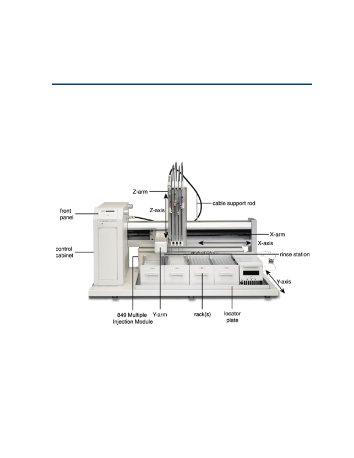
Description
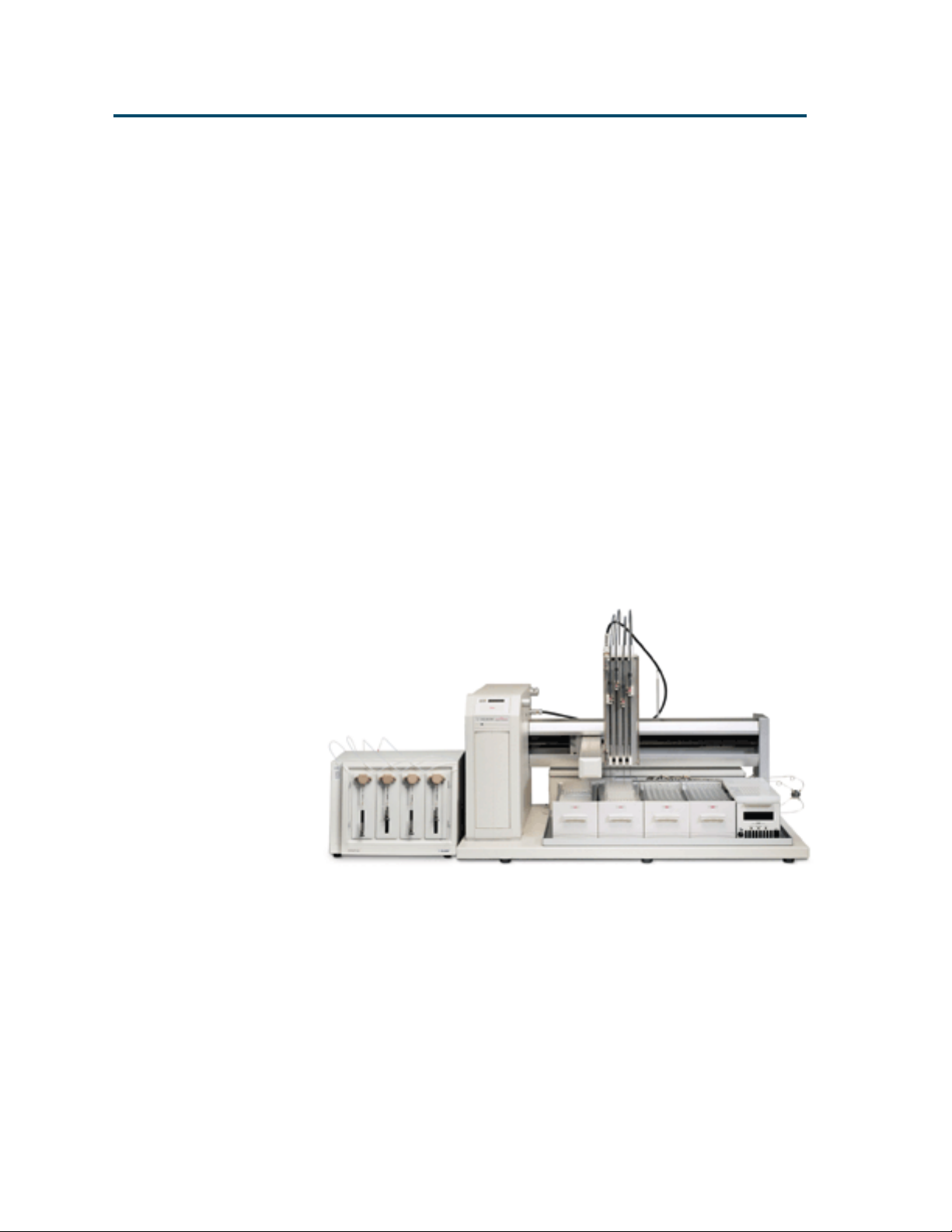
The Gilson Quad-Z 215 Liquid Handler is an XYZ
robot that can automate any number of manual
Description
liquid handling procedures. The Quad-Z has four
independently operated probes with variable
horizontal spacing (from 9 to 18 mm) allowing
access to virtually any tube, vial, or microplate
configuration.
The optional 849 Multiple Injection Module can be
configured with four sample loops of varying
capacities to provide complete flexibility for open
access laboratories. The advanced liquid-level
detection for each independently operated probe
minimizes carryover ensuring accurate and
reproducible results.
The external 444 QuadDilutor provides for the
accurate and precise handling of liquids.
1-2
Page 11

Introduction 1
Unpacking
The Quad-Z 215 Liquid Handler is delivered with
all major components already assembled except for
auxiliary parts such as the Z-arm, probe, racks,
tubing, etc. Keep the original container and
packing assembly in case the liquid handler must
be returned to the factory.
The Quad-Z 215 Liquid Handler and its
components are shipped in two containers:
• One container holds the auxiliary items, such as
locator plate, tubing, probes, rinse station, Z-arm,
and any other accessories you may have ordered
with your system.
• The other container holds the Quad-Z 215
Liquid Handler.
Unpacking
To remove the liquid handler from its container:
1 Cut the metal strapping.
2 Lift the outer box off and away from the liquid
handler.
3 Lift the inner box off and away from the liquid
handler.
4 Lift the unit off its base platform and place it on
a lab bench or cart. Gilson recommends that
two people lift the liquid handler off the base
of the packing container. To lift the liquid
handler:
a) Using the two cutouts for hand holds, place
a hand at the base of the packing container.
b) Grip the liquid handler under the base plate.
c) Lift the unit up and out of the foam packing
material. The side containing the electronics
cabinet is the heavier side.
Do not attempt to lift the instrument from the Y-arm
(the horizontal arm). Always lift the instrument from
its base.
1-3
Page 12

Introduction 1
Standard Equipment
Once the liquid handler and the accessories
containers have been unpacked, you should have
Unpacking
the following:
Quad-Z 215 Liquid Handler
444 QuadDilutor with accessories
Locator plate with one drain base (includes four
mounting screws)
Rinse drain package which includes:
• 2-liter waste bottle
• Cap with quick connect fitting
• Rinse station with fittings
• 5 feet of Tygon waste tubing with quick connect
fitting
Z-arm and control cable with retaining clip and
level sensing cables
Accessory package which includes:
• Fuse drawers, fuses, and power cords
• 10-pin terminal block connector
• 8-pin terminal block connector
• 9/64" ball driver for removal of armlock
• Eight tubing retaining clips
• Cable support rod with bracket and two
Phillips-head attachment screws
• Tubing support rod
215 Utility Programs CD-ROM
444 Utility Programs CD-ROM
Quad-Z 215 Liquid Handler User’s Guide
444 QuadDilutor User’s Guide
Accessories
1-4
Based upon your configuration, you’ll also receive
additional accessories, such as the probes, transfer
tubing, racks, etc. If necessary, refer to Appendix A
for part numbers.
Page 13

Introduction 1
Customer Service
Gilson, Inc. and its worldwide network of authorized
representatives provide customers with the following
assistance: sales, technical applications, and
instrument repair.
If you need assistance, please contact your Gilson
representative or if you are in the United States call
the Gilson Customer Service Department at 800-4457661 or 608-836-1551. You can also contact the
Customer Service Department via its e-mail address:
service@gilson.com. Specific contact information can
be found on the Gilson web site at www.gilson.com.
To help us serve you quickly and efficiently, please
refer to the Before calling us section on page 5-8.
Customer Service
1-5
Page 14

Introduction 1
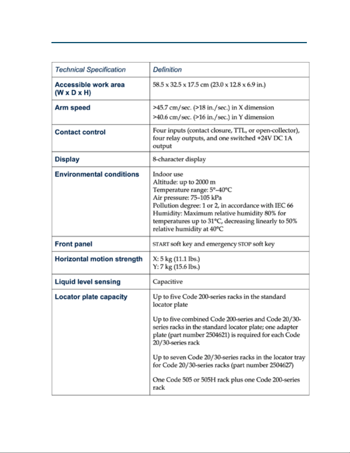
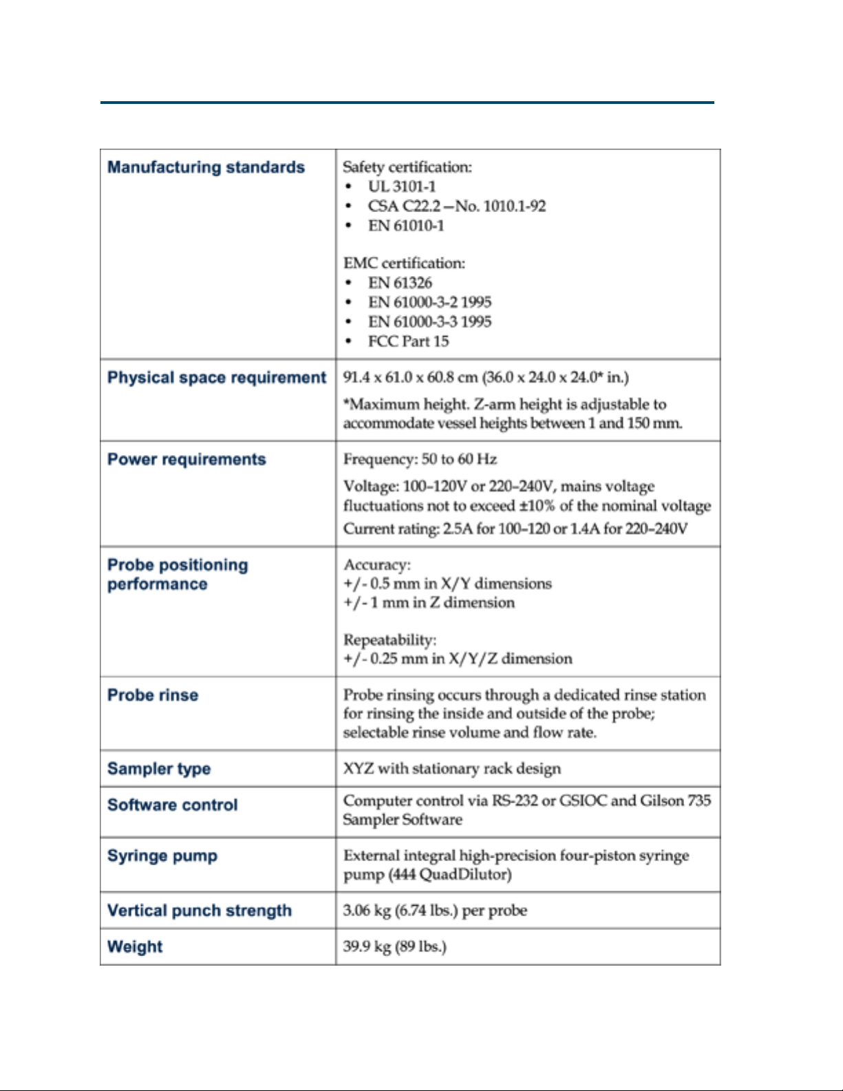
Technical Specifications
Please be aware of the following before operating
the liquid handler.
Warning: Changes or modifications to the liquid
handler not expressly approved by Gilson could
void the factory-authorized warranty.
T echnical Specifications
The liquid handler has been tested and found to
comply with the limits for a Class A digital device,
pursuant to Part 15 of the FCC commercial
environment. The liquid handler generates, uses,
and can radiate radio frequency energy and, if not
installed and used in accordance with the
instructions, may cause harmful interference to
radio communications. Operation of the liquid
handler in a residential area is likely to cause
harmful interference; in which case, the user will
be required to correct the interference at the user’s
own expense.
Shielded cables must be used with the liquid
handler to ensure compliance with the Class A
FCC limits.
1-6
Page 15
Introduction 1
T echnical Specifications
1-7
Page 16
Introduction 1
T echnical Specifications
1-8
Page 17
Installation
This section takes you through the steps for setting up your Quad-Z 215 Liquid Handler.
2
2-1
Page 18
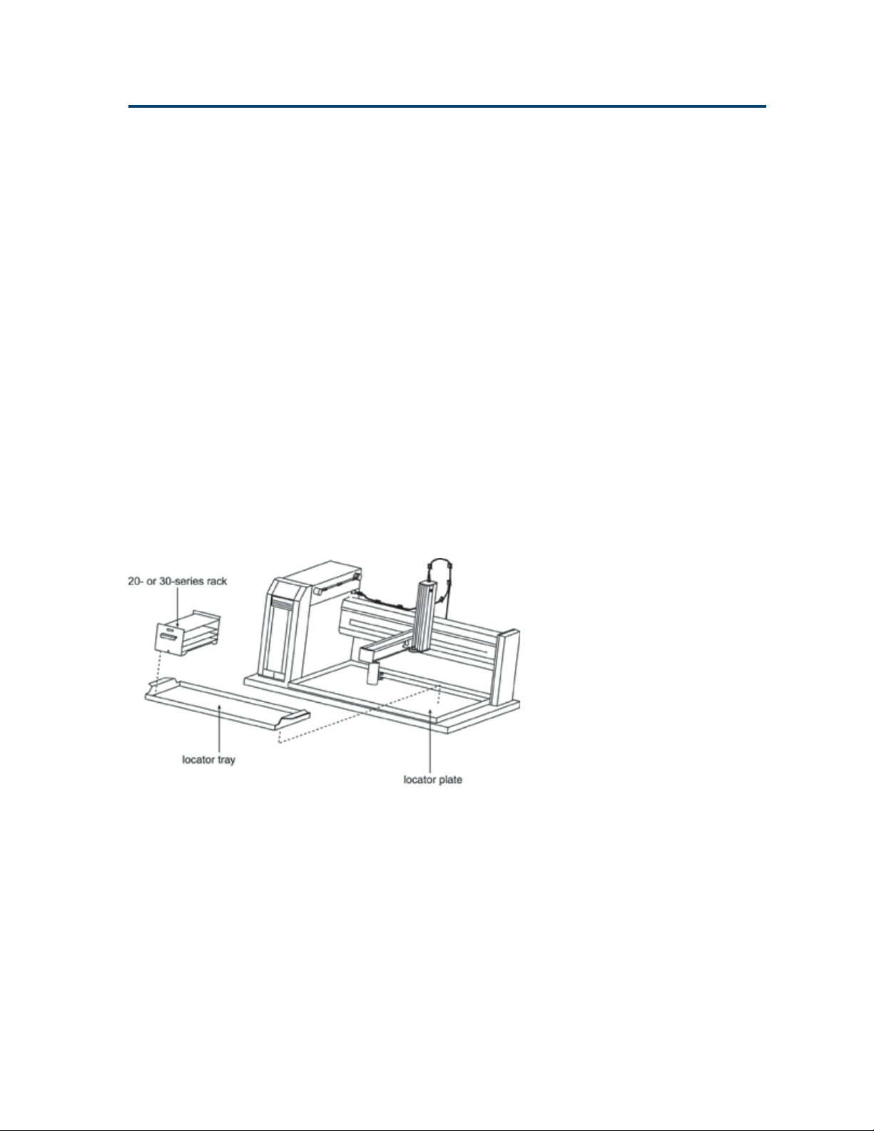
Installation 2
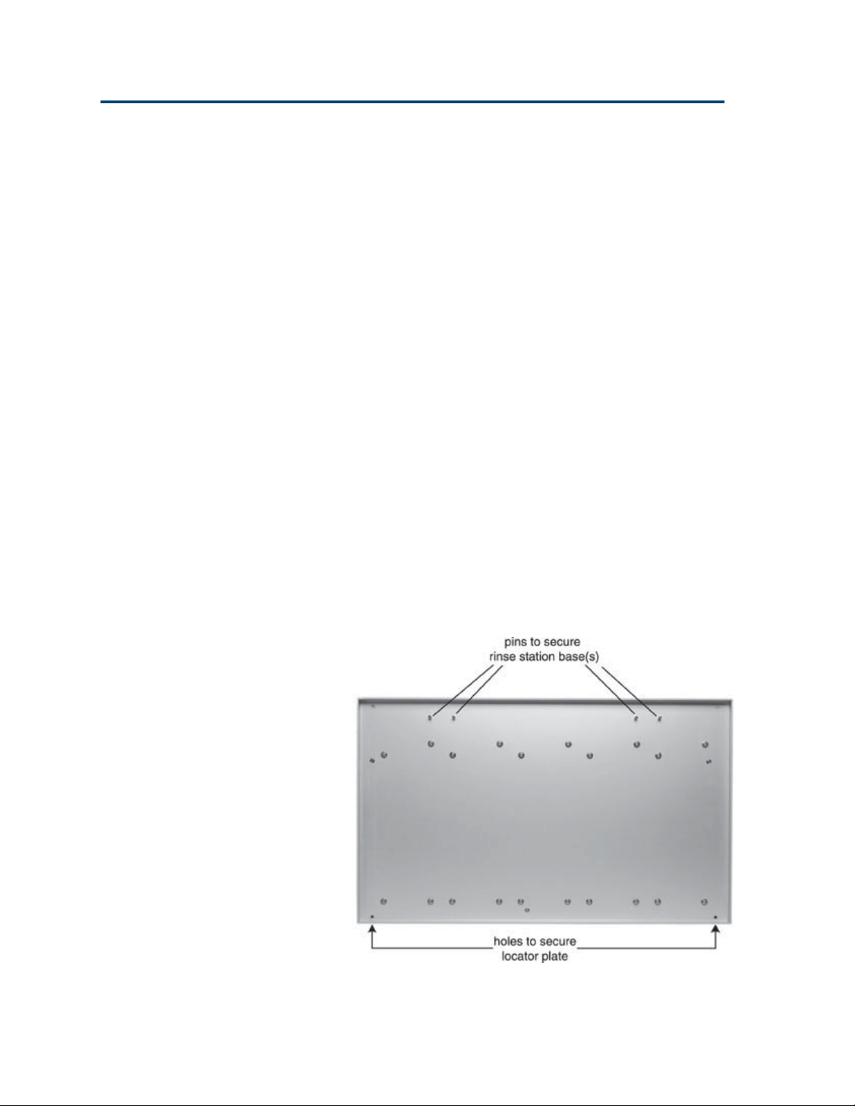
Locator Plate Installation
The locator plate serves two functions:
• Positions the racks and accessories that fit onto
the bed of the liquid handler.
• Contains liquid spills, such as those caused by
overflowing vessels.
Locator Plate Installation
The locator plate and its four mounting screws are
shipped in a separate box with the liquid handler’s
accessories. To install the locator plate onto the
instrument bed:
1 Make sure the locator plate’s rinsing station
base is at the rear of the instrument. The locator
plate will only install in this orientation.
2 Align the four corner holes of the locator plate
with the four holes on the instrument bed and
lower the plate onto the bed.
3 Using a Phillips screwdriver, secure the locator
plate using the four mounting screws.
2-2
Page 19
Installation 2
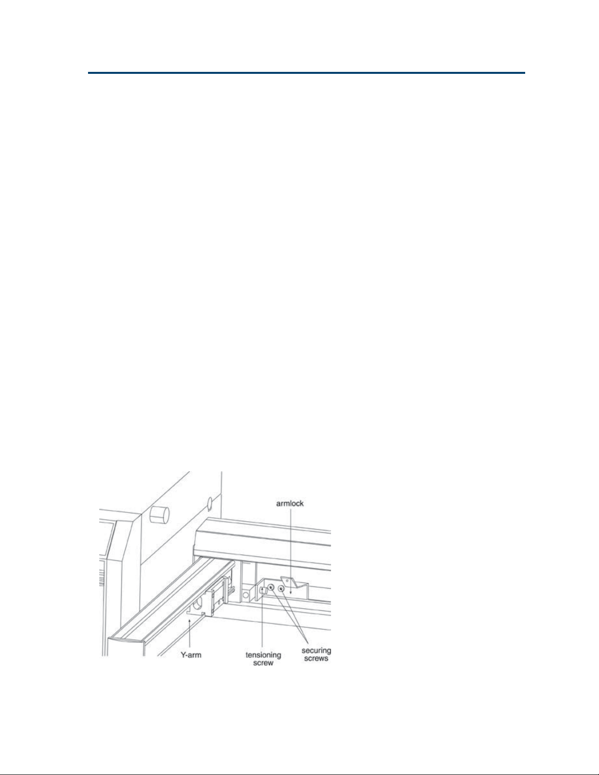
Armlock Removal
The armlock on the liquid handler secures the Y-arm
during shipment. You must remove the armlock
prior to installing the Z-arm and operating the
instrument. If the armlock is not removed, the
liquid handler cannot move in the X-direction. This
results in an error state during operation.
If you need to move the liquid handler, always
reinstall the armlock. This safeguards against
mechanical damage.
To remove the armlock:
1 Remove the cardboard label in front of the
armlock.
Armlock Removal
2 Using the 9/64" ball driver, loosen the
tensioning screw that immobilizes the Y-arm.
3 Using the 9/64" ball driver, remove the two
remaining screws that hold the armlock in
place.
4 Remove the armlock and store it and the ball
driver for future use.
2-3
Page 20
Installation 2
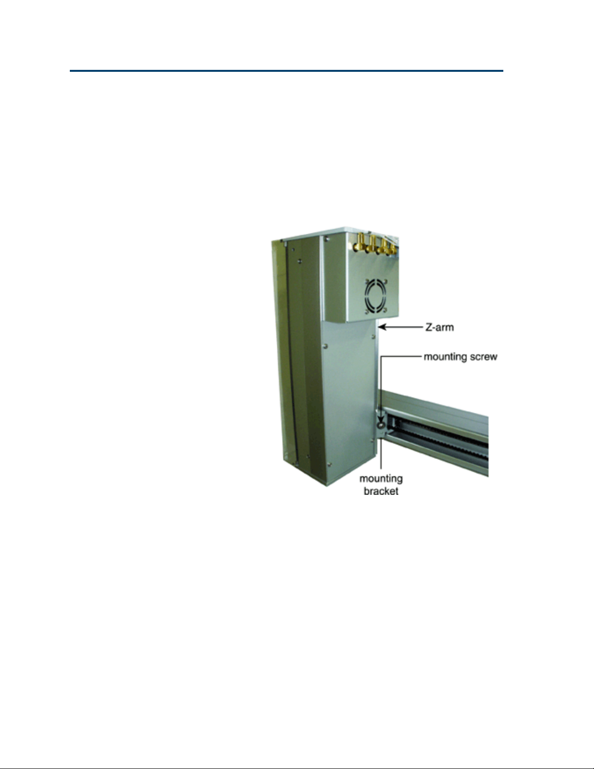
Z-Arm Installation
Follow these steps to install the Z-arm:
1 Using a Phillips screwdriver, loosen the
mounting screw on the Z-arm mounting
Z-Arm Installation
bracket located on the Y-arm. Turn
counterclockwise to loosen.
2-4
2 Partially pull out the bracket. Do not remove
completely.
3 Place the Z-arm into the mounting bracket. You
will need to insert one side of the Z-arm into
place at a time.
4 Tighten the screw on the mounting bracket
until the Z-arm is secure.
You’ll adjust the Z-arm to its proper height
after rack and rinse station installation. This
adjustment is described on page 2-14.
Page 21

Installation 2
Installing the Z-Arm Cable Support Rod
1 Using the two Phillips screws, attach the cable
support rod bracket in the holes located in the
rear of the X-arm extrusion.
Z-Arm Installation
2 Extend the arm to the extreme X- and Y-direction
to ensure that the cable will have enough slack.
Plug the Z-arm control cable into the back topside
of the control cabinet. The control cable should be
tucked into the groove located in the top of the
X-arm extrusion. The retaining clip that is already
on the control cable should be snapped onto the
top of the cable support rod. Refer to diagram
below.
2-5
Page 22
Installation 2
Probe Installation
There are different probes available for use on the
Quad-Z 215 Liquid Handler. Depending upon your
application, you have purchased the appropriate
probes and probe guide inserts. When installing the
Probe Installation
probes or custom sized probe guide inserts (1.3 or
1.5 mm) refer to the following procedures and
diagrams.
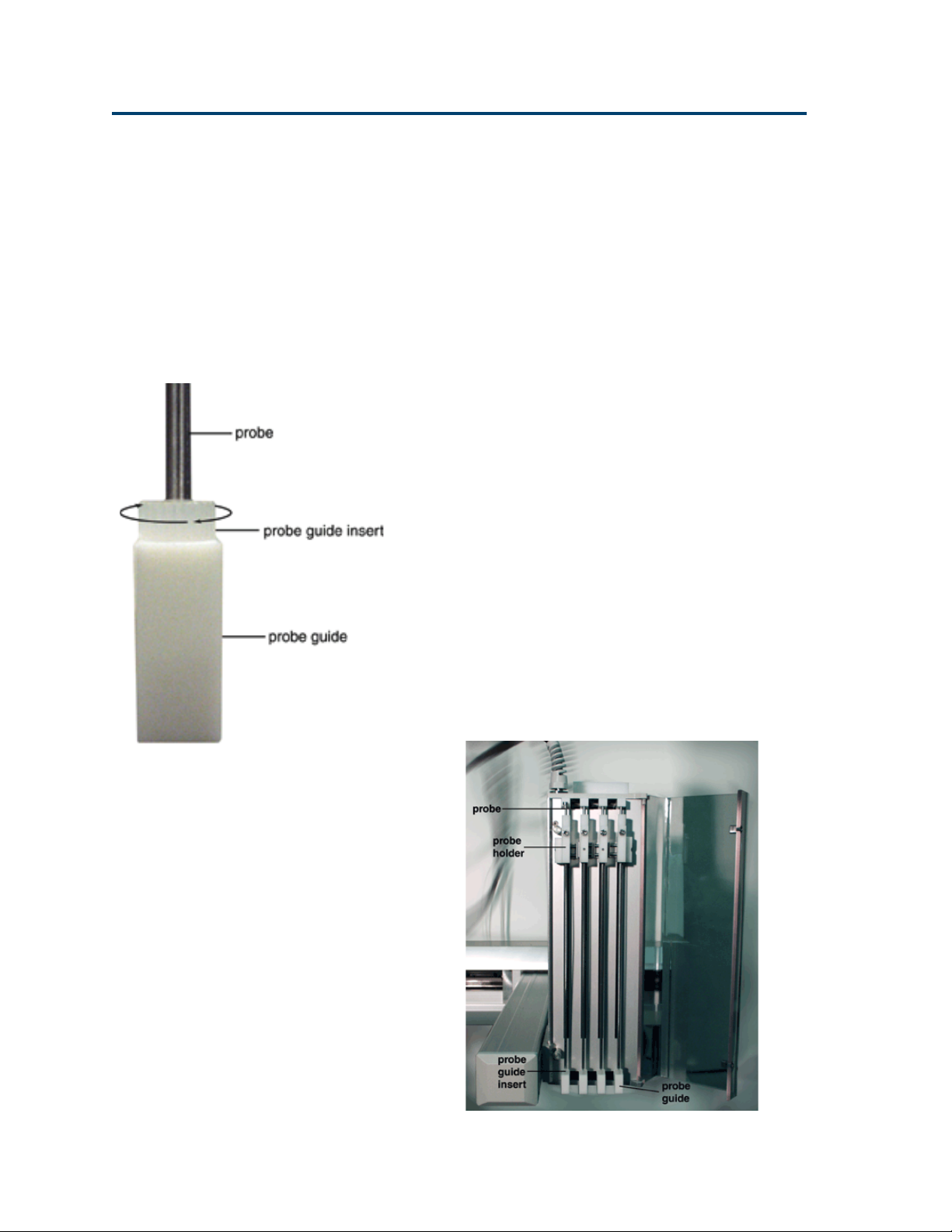
Installing the Probe Guide Inserts
Your Quad-Z is delivered with 1.5 mm probe guide
inserts installed. If you ordered custom sized probe
guide inserts for more precise XY accuracy, refer to
the installation instruction below.
To install the probe guide inserts, turn the insert
clockwise into the probe guide.
Installing the Probes
Insert the probes into the top of the isolation probe
holders and pull them through the holders and the
probe guide inserts until the tip of the probe is in
the probe guides.
2-6
Page 23

Installation 2
Plumbing Connections
Transfer Tubing Installation
1 Connect one end of each piece of transfer
tubing to the 444 QuadDilutor. Refer to the 444
QuadDilutor User’s Guide for more information.
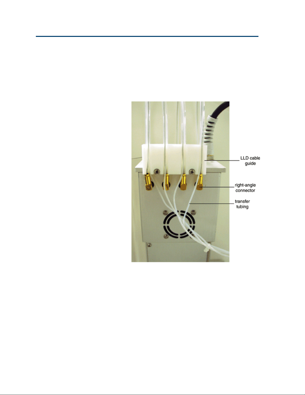
2 Locate the level sensing cables (LLD cables)
supplied with the Z-arm.
3 Pass the other end of each transfer tubing
through the open end of an LLD cable casing
nearest the right-angle connector. The tubing
should exit the back of the LLD cable casing
approximately 6.5 cm from the end.
4 Connect each tubing to the top of the isolation
probe holder using a 1/4"-28 nut and ferrule
supplied with the tubing. Firmly tighten this
fitting using the supplied headless nut extender
(part number 49041032) since it holds the probe
in place.
Plumbing Connections
2-7
Page 24
Installation 2
Installing the Level Sensing Cables
To install the level sensing cable:
1 Plug the right-angle connector on one end of the
cable into socket one on the back of the Z-arm.
Plumbing Connections
2-8
2 Snap the cable into the LLD cable guide (refer
to the picture above).
3 Loosen the small hexagonal nut on the probe
holder for probe one. Attach the split-tongue
connector to the nut. Retighten the nut until
snug (approximately one turn after finger
tightening).
4 Repeat for probes 2 through 4.
Page 25
Installation 2
Rinse Station and Drain Waste Tubing Installation
You’ll clean the probe using the rinse station. To
eliminate carryover of liquids, the rinsing procedure
pumps an excess volume of diluent or probe
washing solution through the probe and out into
the rinse station. The small diameter of the rinse
station inserts allow the outside of the probe to be
washed along with the inside.
The rinse station’s design accommodates three
kinds of rinses:
• Shallow-pocket rinse - Used
for level sensing applications
where the probe is only
immersed in a few
millimeters of the sample.
Plumbing Connections
• Deep-pocket rinse - Used
for non-level sensing
applications. This type of
insert allows for a deeper
insertion of the probe into
the rinse well resulting in a
greater area of the outside
of the probe to be rinsed.
• Flow-through rinse - Used
in applications where a
rigorous wash of the
probe’s exterior is required.
A second source of liquid is pumped to the
rinse station to perform this type of rinse.
It may be necessary to vary the types and
volumes of probe wash solutions to most
efficiently eliminate carryover of particular
compounds. Generally, the smaller the volume
of probe wash solution used, the faster your
automated liquid handling protocol.
2-9
Page 26
Installation 2
Installing the rinse station
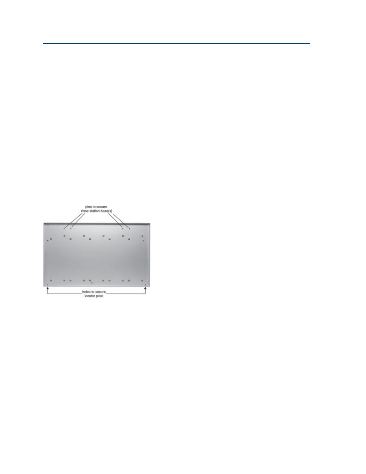
The base of one rinse station is shipped already
secured to the locator plate and is located at the
rear of the locator plate. The locator plate can hold
an optional second rinse station or you can move
the rinse station base to the alternate location.
Before installing the rinse station, make sure the
Plumbing Connections
locator plate has been properly installed with the
previously-installed rinse station base located at the
rear of the instrument bed.
To install the rinse station onto the base, follow
these steps:
1 Align the triangle on the bottom of the rinse
station with the base.
2 With the rinse station’s fittings facing you,
insert the rinse station into the base.
3 Press down and turn the rinse station clockwise.
The rinse station is secure when you feel the
rinse station snap into place. When installed
correctly, the fittings point toward the control
cabinet.
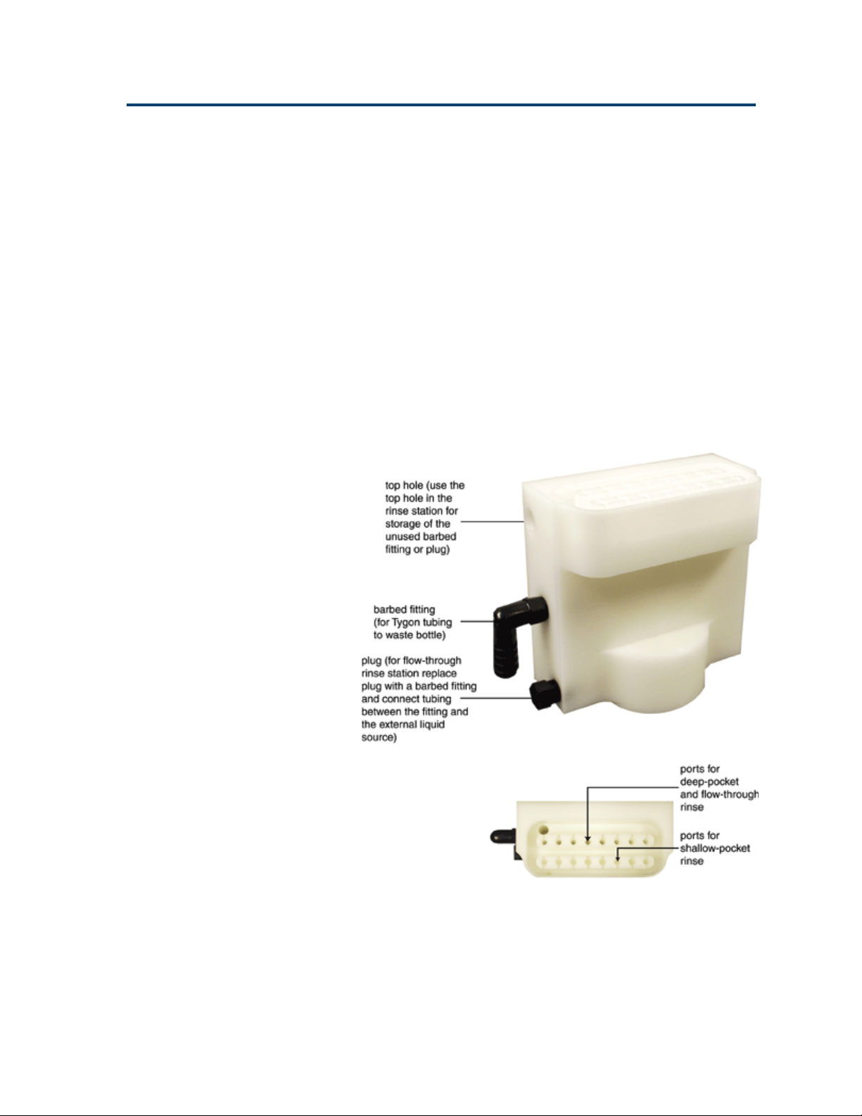
4 If you will be doing shallow- or deep-pocket
rinses, connect waste tubing to the barbed
fitting installed on the rinse station.
If you will be doing flow-through rinses,
remove the plug installed on the rinse station
and replace it with a barbed fitting. Connect
tubing between the barbed fitting and the
external liquid source.
2-10
Page 27

Installation 2
Rack Setup
The Quad-Z 215 Liquid Handler is equipped to
locate Code 20-, 30-, 200-, and 500-series racks. See
Appendix B for a list of racks available for the liquid
handler.
Depending on the racks you’re using, refer to the
appropriate procedures on the following pages.
Code 200-Series and Code 500-Series Racks
If all your racks are Code 200-series or Code 500series racks, place them directly onto the locator
plate:
1 Orient the rack so that the code number (for
example, 200) is facing forward.
Rack Setup
2 Fit the rack on the locator plate so that the slots
and holes on the underside of the rack align
with the pins on the locator plate.
2-11
Page 28
Installation 2
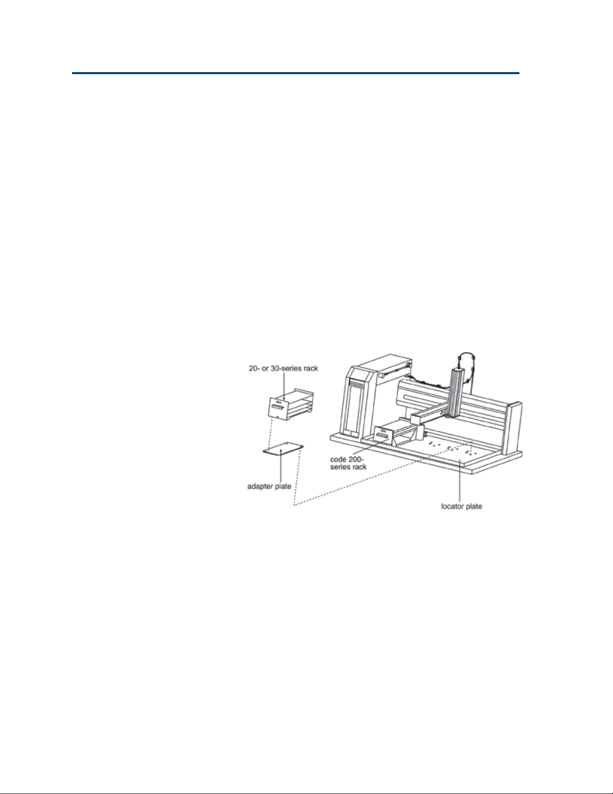
Code 200-Series and Code 20-Series or Code 30-Series Racks
To use a combination of Code 200-series and Code
Rack Setup
20-series or Code 30-series racks on the locator
plate:
1 Install each Code 200-series rack as described
on page 2-11.
2 For each Code 20-series or Code 30-series rack,
place an adapter plate onto the locator plate. Fit
the plate so that the slots on the adapter plate
align with the pins on the locator plate.
3 Place the Code 20-series or Code 30-series rack
onto the adapter plate.
2-12
Page 29
Installation 2
Only Code 20-Series or Code 30-Series Racks
If all your racks are Code 20- or Code 30-series racks
and you do not have the optional 849 Multiple
Injection Module installed, follow the steps below.
1 Install the locator tray (part number 2504627,
ordered separately) onto the locator plate of the
liquid handler.
• For Code 20-series racks, the handles face
the front.
• For Code 30-series racks, the hose fittings
should face the back.
2 Position each rack onto the locator tray. You
can install up to seven racks using this tray.
Rack Setup
2-13
Page 30
Installation 2
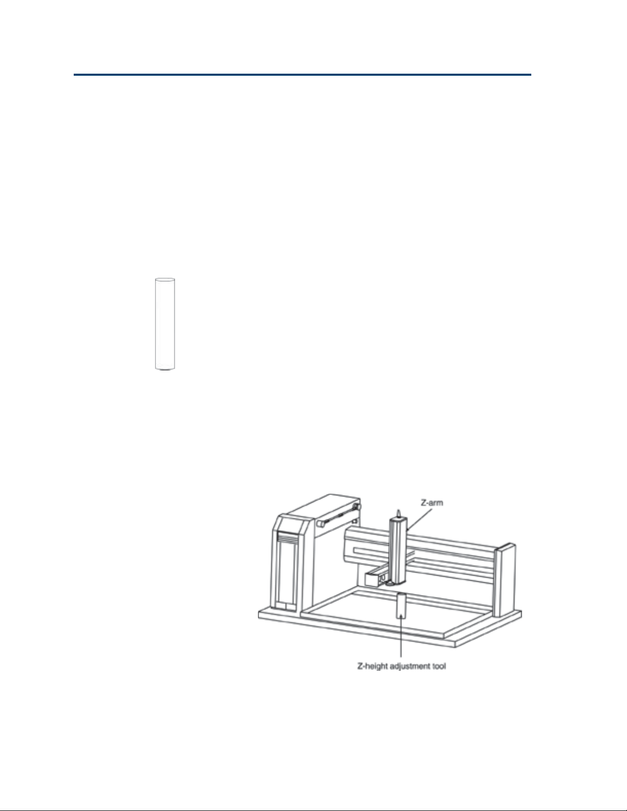
Final Z-Arm Adjustment
Follow these steps to adjust the Z-arm to the proper
height.
1 Turn off power to the liquid handler.
2 Locate the appropriate Z-height adjustment
tool in the accessory package. Two Z-height
Final Z-Arm Adjustment
adjustment tools are supplied in the package.
Part number Description
25051094 125 mm Z-height adjustment tool.
Use this tool to adjust the Z-arm
on the Quad-Z 215 Liquid Handler
for liquid handling and injection.
Z-height
adjustment tool
25051095 175 mm Z-height adjustment tool.
Use this tool to adjust the Z-arm
on the Quad-Z 215 Liquid Handler
for liquid handling.
3 Place the Z-height adjustment tool on one of its
ends near the center of the locator plate (if
necessary, remove any racks or accessories
before doing this).
2-14
Page 31

Installation 2
4 Loosen the mounting screw on the Z-arm
mounting bracket and slightly raise the Z-arm.
Final Z-Arm Adjustment
5 Manually move the liquid handler’s arm so the
Z-arm is centered over the Z-height adjustment
tool.
6 While holding Z-height adjustment tool flat
against the locator plate, use the other hand to
lower the Z-arm until it lightly rests on the
adjustment tool.
7 Tighten the mounting screw on the Z-arm
mounting bracket so the Z-arm is secure.
8 While holding the adjustment tool in place,
slide the Z-arm off the tool. Ensure that the
bottom of the Z-arm lightly rubs against the
adjustment tool as it moves. Repeat steps 4
through 7 until this is true.
9 Store the Z-height adjustment tool.
2-15
Page 32

Installation 2
Electrical Connections
Rear Panel
1 Input/Output (I/O) ports
2 Gilson Serial Input/Output Channel (GSIOC) port
3 Keypad port (not used on the Quad-Z)
4 RS-232 port
Electrical Connections
5 Fuse drawer
6 Power switch
7 Power receptacle
8 Unit ID selector
9 Baud rate/mode selector
2-16
Page 33

Installation 2
Input/Output Ports
You can use the input and output contacts found
on the rear panel of the liquid handler to control
peripheral devices. Refer to the diagram on page
2-16 for the location of the input/output ports.
Contact inputs
The input terminal block of the liquid handler has
eight contacts. All of the inputs are paired, and
each pair includes a GROUND reference ( ).
The contact input pairs are labeled A, B, C, and D.
A contact is connected if it has a short across the
input or is held low by a TTL output or other
device.
Electrical Connections
Never connect voltages higher than 5V DC to an
input. When using TTL signals, be sure to match
GROUND connections.
Contact outputs
The output terminal block has 10 contacts.
Pins 1 and 2 supply a +24V DC output. Do not use
this output unless the receiving device can accept
24V power.
Pins 3 through 10 are paired, isolated-relay contact
closures and are labeled 1, 2, 3, and 4.
Items you’ll need
To make connections, you’ll need the following:
• 2-conductor cable (22–30 gauge for each wire)
• wire insulation stripper
• small-blade screwdriver
You can purchase a 6-foot piece of suitable cable
(part number 709910206) or a package of five
cables with identification markers (part number
36078155) from Gilson.
2-17
Page 34

Installation 2
Making connections
To prepare and make connections with the 2conductor cable:
1 Cut the cable into pieces of appropriate length.
2 Strip about 0.25 cm of insulation from each end
of the cable.
Electrical Connections
3 Remove the terminal block connector from the
liquid handler. Insert each wire into the
appropriate slot on the terminal block connector.
Note: When making connections, be sure to
maintain the correct orientation of the connector
relative to the port.
Push the wire all the way in; then tighten its
corresponding pin screw.
4 Reconnect the terminal block connector to the
liquid handler. The wires will be facing left and
the pin screws will be facing you as you look at
the rear of the instrument. Push the connector
in as far as it will go. It is designed to fit snugly
into its receptacle.
5 Connect the opposite ends of the wires to the
other device(s). Be sure to match ground
connections.
6 Label each cable to identify the purpose of the
connection.
2-18
Page 35

Installation 2
RS-232 Port
The RS-232 port is used to transfer information
between the liquid handler and a computer. For the
location of the RS-232 port, refer to the diagram on
page 2-16.
Be sure your computer is turned off before making
any connections.
To connect your computer to the liquid handler,
you’ll need an RS-232 cable. Obtain a cable with
D-connectors that are appropriate for the liquid
handler and your computer. The liquid handler
requires a 25-pin male D-connector. Refer to the
back panel of your computer or its documentation
to determine which type of D-connector it requires.
RS-232 cables are available from Gilson and your
local computer store.
Electrical Connections
Connecting an RS-232 cable
Attach the male end of the RS-232 cable to the
RS-232 port located on back panel of the Quad-Z
215 Liquid Handler. Tighten the retaining screws.
Attach the female end of the RS-232 cable to the
computer’s RS-232 serial communications port. (Do
not mistake it for the female 25-pin parallel printer
port!) Again, tighten the retaining screws.
2-19
Page 36

Installation 2
GSIOC Port
Gilson systems feature a two-way communication
interface between the computer and most Gilson
modules. Communication occurs along the Gilson
Serial Input/Output Channel (GSIOC).
The liquid handler can convert the RS-232 signal
levels used by computers to the RS-422/485 signal
Electrical Connections
levels required by the GSIOC and vice versa. (See
page 2-19 for information on making the RS-232
connection between the liquid handler and
computer.)
GSIOC cable
Use the GSIOC cable to link an additional Gilson
GSIOC module to the liquid handler and control
both devices via a program executed on the
computer.
2-20
Connect the female connector, located individually
at one end of the cable, into the GSIOC port of the
liquid handler. Tighten the retaining screws. (Refer
to diagram below.)
Connect the other female connector, located on the
same end as the male connector, to the Gilson
module. Tighten the retaining screws.
If you’re connecting another Gilson module, use the
male connector to join another GSIOC cable and
make the necessary connection to the next Gilson
module.
Page 37

Installation 2
Unit ID and Baud Rate/Mode Selection
Use the SW1 selector to choose a different unit ID
and the SW2 to choose a different baud rate/mode.
If necessary, refer to the diagram on page 2-16 for
the location of these selectors.
Unit ID
The unit ID identifies the liquid handler to Gilson
software packages that can issue GSIOC
commands to the liquid handler.
At the factory, Gilson set the unit ID to 22. There is
no need to change this number unless it is the same
as that assigned to another Gilson device that’s also
connected along the GSIOC.
Electrical Connections
To change the unit ID:
1 Gently insert a small flat blade screwdriver into
the SW1 selector on the rear panel and turn it.
2 Align the white dot with one of the indicated
numbers. The unit ID is 20 plus the selected
number.
2-21
Page 38

Installation 2
Baud rate/mode
As a default, the baud rate/mode is set to 6,
indicating that the liquid handler is set for a baud
rate of 19200 and is a master device.
You’ll need to change the selection to 0 (zero) if the
liquid handler is connected via the GSIOC to a
Gilson system and is being controlled by the 506C
Electrical Connections
System Interface from Gilson control software. A
setting of 0 indicates the liquid handler is a slave
device and the baud rate is being clocked
externally.
Note that other selections are available if the liquid
handler is being controlled by non-Gilson
applications. Refer to the table shown on the liquid
handler’s rear panel; see page 2-16.
To change the baud rate/mode:
1 Gently insert a small flat blade screwdriver into
the SW2 selector on the rear panel and turn it.
2 Align the white dot with one of the indicated
numbers.
2-22
Page 39

Installation 2
Fuses
You received the liquid handler without any fuses
installed. To install the fuses:
1 Locate the accessory package containing the
fuse drawer appropriate for your line voltage.
Discard the other fuse drawer.
2 Locate the accessory package containing the
5.0A “T” Slo-Blo fuse (5 x 20 mm size) fuses.
3 Install the fuse(s) into the fuse drawer. The fuse
drawer for 100/120V accepts one fuse. The fuse
drawer for 220/240V accepts two fuses.
4 Insert the fuse drawer into its receptacle in the
liquid handler. See rear panel diagram on page
2-16.
Fuse installation for 100/120 voltage
Electrical Connections
Fuse installation for 220/240 voltage
2-23
Page 40

Installation 2
Power Cord Connection
Locate the appropriate power cord for your line
voltage. Discard the other power cord.
Use the power cord to connect the liquid handler to
an AC power source.
Electrical Connections
2-24
Page 41

Operation
The Quad-Z 215 Liquid Handler is controlled as follows:
• Via a method running on a personal computer. You create the method using 735
Sampler Software (ordered separately, part number 2106773532).
If you have not already done so, install the 735 Sampler Software. Refer to the
documentation supplied with the software.
3
3-1
Page 42

Operation 3
Front Panel
The front panel of the liquid handler contains a
Start button, Stop button, LED display, and power
Front Panel
indicator light.
Start Button
The Start button can be used to home the XYZ-arm
when the liquid handler is first powered up or
when the motors for the XYZ-arm have been
relaxed. When pressed, the yellow LED lights.
Stop Button
The Stop button is a large touch-sensitive pad that
can be used to terminate a program and stop the
liquid handler from responding to any more
commands coming from the running program. This
button also relaxes the motors for the XYZ-arm so
that you can easily lift the probe and move the arm.
When pressed, the yellow LED light is turned off.
In a situation where an emergency stop is required,
pressing the Stop button immediately stops the
liquid handler. The Stop button is designed to be
sensitive enough that if you just brush it with your
hand it activates.
LED Display
The 8-character LED display shows the current
status of the liquid handler and any error codes as
they are encountered. Your program can also
contain instructions for showing 8-character
messages on the display when the program is run.
Refer to Section 5, Troubleshooting for a list of
current error codes and required actions.
Power Indicator Light
This indicator becomes lit when you turn on power
to the liquid handler using the power switch located
on the rear panel. Refer to the rear panel diagram
on page 2-16 if necessary.
3-2
Page 43

Operation 3
St art Up
To start the liquid handler:
1 Make sure the liquid handler is connected to a
power source.
2 Turn on the liquid handler using the power
switch located on the rear panel. Refer to rear
panel diagram on page 2-16 if necessary. The
power indicator light on the front panel
illuminates.
When power is turned on, the liquid handler
beeps and displays the current version of its
installed firmware. This message appears for
about one second before the LED display
returns to a blank state.
Start Up
In order to determine what PROM version is
installed in your liquid handler, you may need
to turn the unit off then on again and watch
the display for the version number to appear.
3 After the liquid handler powers up, press the
Start button. This initiates the homing sequence
that allows the liquid handler to determine its
mechanical reference positions. The sequence
takes approximately one minute to complete.
While the homing sequence progresses, the LED
display shows Homing. When the sequence
completes, it blanks.
Note: If the program being executed by the
liquid handler doesn’t include commands for
homing the instrument, perform step 3 before
starting the program.
The utility programs, supplied with the liquid
handler, home the instrument if necessary.
3-3
Page 44

Operation 3
Running Programs
The liquid handler is controlled by programs
executed from a personal computer.
Executable (.EXE) programs can be run from a
computer. The computer is connected to the liquid
Running Programs
handler via an RS-232 cable. Refer to Section 2 for
correct installation of the RS-232 cable between the
liquid handler and the computer.
The following utility programs may be used with
the Quad-Z 215 Liquid Handler and are supplied
on the 215 Utility Programs CD-ROM supplied
with your liquid handler.
215 Setup Utility - Specifies configuration
parameters for the liquid handler.
215 Contact Test Utility - Enables you to test
contact connections.
3-4
Page 45

Operation 3
Configuring the Liquid Handler
The liquid handler comes from the factory with
its configuration set by Gilson. Configuration
information is stored in the non-volatile memory of
the liquid handler. Prior to using the liquid handler
for the first time, it is important to review and
adjust the default configuration to make sure it is
correct for your application.
The following pages describe how to use 215 Setup
Utility to configure the liquid handler. This
information is also available in the on-line help
supplied with the program.
When you execute the 215 Setup Utility from the
computer, the following tabs appear:
Configuring the Liquid Handler
• about
• pump type
• syringe options
• rinse site
• liquid detector
• adjust XY
• Z height
• home phase
• safety contact
• bearing life
• sound & display
• emergency contact
Following is a description of each of the tabs.
3-5
Page 46

Operation 3
About
Configuring the Liquid Handler
The About tab allows you to indicate the unit ID of
the instrument being configured so the 215 Setup
Utility can communicate with that instrument.
This tab also lists software version and copyright
information for the 215 Setup Utility.
Unless the Non-Volatile RAM has been cleared,
information about the type of 215 you are using
will appear automatically. You will see the
following indicating that you are using a Quad-Z
215 Liquid Handler: 215QADvX.XX.
3-6
Page 47

Operation 3
Pump Type
Because the Quad-Z 215 Liquid Handler uses an
external dilutor, Blank Front is selected and all
options are inactive.
Configuring the Liquid Handler
Syringe Options
All options on this tab are inactive for the Quad-Z
215 Liquid Handler because it has an external
dilutor.
3-7
Page 48

Operation 3
Rinse Site
Configuring the Liquid Handler
The instrument stores the location of a rinse site in
memory. This allows the instrument to move to this
location before homing the syringe and prevents
the spilling of waste liquid or rinse diluent.
You must modify the rinse site coordinates if you
have a Quad-Z 215 Liquid Handler. Refer to the
following table to select the correct X, Y, and Z
coordinates depending on the kind of probe rinse
that will be performed. Coordinates for the rinse
site are provided for the X, Y, and Z axis in
millimeters. The coordinates identify the rinse site
for the left-most probe installed on the Quad-Z 215
Liquid Handler.
XYZ
Shallow-pocket rinse 82.9 16.5 100.0
Deep-pocket rinse 82.9 3.8 47.5
Flow-through rinse 82.9 3.8 47.5
3-8
Page 49

Operation 3
Liquid Detector
The Liquid Detector tab allows you to adjust the
default sensitivity for liquid detection.
Note: Gilson control software (such as 735 Sampler
Software) will override these settings.
Configuring the Liquid Handler
Raising the percentage suppresses false liquid
detection while lowering the percentage increases
sensitivity for situations where liquid is harder to
detect. By lowering the probe so it touches the
liquid for one of your samples, you can manually
test the current sensitivity of the liquid detection. In
this manner, you can observe the amount of
change you might expect with each sample.
The factory default setting is 10% for each probe.
3-9
Page 50

Operation 3
Adjust XY
Configuring the Liquid Handler
The Adjust XY tab allows you to test whether the
instrument is properly adjusted and to make minor
adjustments to the X- and Y-axis offsets if needed.
You may need to use the options under this tab if
the probe is not accessing the injection port of the
injection module installed or the vessels in the
installed racks.
The X offset and Y offset text boxes display the
current offsets stored in the instrument’s memory.
To determine if the probe(s) need(s) to be adjusted
in the X or Y direction select the model of the
injection module that is on your Quad-Z 215 or
select other for a user-defined test point. The
default XY coordinates are shown next to the
model number.
Select the model of the injection module that is on
your 215 or select other for a user-defined test
point. The default XY coordinates are shown next
to the model number.
3-10
Page 51

Operation 3
model 819:
X-coordinate: 544.0 mm
Y-coordinate: 3.8 mm
If the model 819 is not installed next to the right
support use the following coordinates:
X-coordinate: 351.1 mm
Y-coordinate: 1.3 mm
model 841:
X-coordinate: 475.3 mm
Y-coordinate: 3.8 mm
model 889:
X-coordinate: 336.1 mm
Y-coordinate: 3.8 mm
model 849:
X-coordinate: 336.1 mm
Y-coordinate: 3.8 mm
other:
Configuring the Liquid Handler
3-11
Page 52

Operation 3
Z Height
Configuring the Liquid Handler
Use the Z Heights tab to identify the size of the
installed Z-arm and the height at which the Z-arm
is clamped.
The tower height options are inactive for the Quad-Z
215 Liquid Handler because there is only one tower
height available.
The Z-arm can be clamped at an adjustable height
over the locator plate. You can set this height so that
the liquid handler is able to properly find heights that
you specify. Type the clamp height in millimeters. A
clamp height of 0 mm means the Z-arm is flat on the
locator plate.
3-12
Page 53

Operation 3
Home Phase
Use the Home Phase tab to display the current Xand Y-phase of the instrument.
Clicking Start causes the liquid handler to perform
the phase procedure. This procedure consists of the
liquid handler homing itself 10 times.
Configuring the Liquid Handler
The liquid handler finds out where home is located
by “feeling” for the back and left walls of the unit.
The liquid handler expects to find these walls in the
same place each time. If it does not, you will get an
error. If this error was caused by an obstruction,
just clear the obstruction and try again. If the
problem does not clear or if a change is made to the
mechanics, you will probably need to repeat this
option to find the true home location.
Once the process completes, the spreadsheet
displays the values generated from each phase
procedure.
3-13
Page 54

Operation 3
Safety Contact
Configuring the Liquid Handler
The instrument has provisions for connecting safety
devices that your application may require, as long
as they present a contact closure or TTL type
interface. The Safety Contact tab allows you to
specify which input contact is connected to the
safety device and what is the active state of that
device. The function of the safety contact is
equivalent to pressing the Stop button on the
instrument’s front panel.
Bearing Life
The Bearing Life tab displays the XYZ travel in
kilometers.
3-14
Page 55

Operation 3
Sound and Display
Use the options in the Sound and Display tab to
adjust the brightness of the display, sound level,
and tone.
Clicking Beep tests the sound level and tone that
are currently selected.
Configuring the Liquid Handler
For the L.E.D. brightness, you can select a range of
0 through 7 where 0 is the dimmest and 7 is the
brightest. Default setting is 5.
Emergency Contact
The emergency stop option provides for sending a
signal to a peripheral device (such as a Gilson 818
AutoMix) whenever the liquid handler’s Stop
button is pressed or safety input is activated.
Note: Once an emergency output has been
activated, reset the contact to its non-emergency
state using the 215 Contact Test Utility.
3-15
Page 56

Operation 3
T esting the Liquid Handler’s
Contact s
Following is a description of how to use the 215
Contact Test Utility to toggle output contacts to
determine if the correct contact connections have
been made to peripheral devices to be controlled by
the Quad-Z 215 Liquid Handler. The program also
identifies the state of input contacts and lets you
test the Start and Stop buttons on the liquid
handler.
Before using this software, you need to connect the
peripheral device’s inputs to the appropriate
output pair on the liquid handler. If necessary,
T esting the Liquid Handler’s Cont acts
refer to Section 2, Installation for information on
making contact connections.
3-16
Page 57

Maintenance
To obtain optimum performance and maximum life from the Quad-Z 215 Liquid Handler,
it is important to keep the instrument well-maintained.
This section contains some general guidelines that will help you to maintain your liquid
handler.
4
4-1
Page 58

Maintenance 4
Helpful Hints
In order to keep your liquid handler at peak
performance, Gilson recommends that you do the
Helpful Hints
following:
• Change or clean the tubing regularly to
maintain maximum performance.
• Flush the probe housings and rinse stations
daily with distilled or deionized water. On a
weekly basis, flush with a 10% solution of
bleach or weak detergent.
• Check periodically to ensure that all fittings are
tight.
• Wipe up all spills immediately.
• Cold fluids may cause leakage; warm fluids to
room temperature before running them through
the system.
• Lubricate the rods on the Z-arm at least once
every six months (see page 4-7).
4-2
Page 59

Maintenance 4
Cleaning
Cleaning the Liquid Handler
The liquid handler should be cleaned occasionally
using a dry, clean cloth. Or, if necessary, use a cloth
dipped in soapy water. If liquid is accidentally
spilled on the liquid handler, wipe the instrument
using a dry, clean cloth.
Cleaning the Fluid Path
Depending on your use of the liquid handler, it
may be necessary to flush the entire fluid path.
It’s important to clean the fluid path if you won’t
be using the liquid handler for a while or if you’re
using a solution with a high salt concentration for a
probe wash or as a diluent.
Cleaning
Prime the system using distilled or deionized water.
Check the beaker during the priming sequence to
ensure it always has liquid in it.
4-3
Page 60

Maintenance 4
Cleaning methods
Depending on the samples or reagents that come
Cleaning
into contact with the fluid path, you may need to
vary your cleaning methods accordingly. Use the
following cleaning protocols as references and make
any changes to them as required for the samples and
reagents being pumped for your application.
Proteins and peptides - Follow this procedure if
the fluid path is in contact with proteins and
peptides:
1 Prime the fluid path using a weak detergent
solution.
2 Pause the priming sequence.
3 After 30 minutes, resume priming the fluid path
using distilled or deionized water to pump the
remaining detergent from the tubing into a waste
container. Prime the fluid path a minimum of 10
cycles with distilled or deionized water.
4 When you’re satisfied that the entire fluid path
has been flushed with water, end the priming
sequence.
4-4
Page 61

Maintenance 4
Acidic and basic compounds - Follow this
procedure if the fluid path is in contact with acidic
and basic compounds:
1 Prime the fluid path using a 0.1N NaOH
solution.
2 Pause the priming sequence.
3 After 10 minutes, resume priming the fluid path
using distilled or deionized water. Prime until
the fluid path has been flushed with water.
4 Pause the priming sequence.
5 Prime the fluid path using a 0.1N NaOH
solution. Continue to prime until the fluid path
has been flushed with 0.1N NaOH.
6 Pause the priming sequence.
7 After 10 minutes, resume priming the fluid path
using distilled or deionized water. Prime until
the fluid path has been flushed with water.
Cleaning
8 When you’re satisfied that the entire fluid path
has been flushed with water, end the priming
sequence.
4-5
Page 62

Maintenance 4
Biological fluids - Follow this procedure if the
fluid path is in contact with biological fluids such
as blood products:
Cleaning
1 Make a solution of 10% bleach by adding one
part of commercial bleach to nine parts of water.
2 Prime the fluid path using the bleach solution
until the entire fluid path has come into contact
with bleach.
3 Pause the priming sequence.
4 After 30 minutes, resume priming the fluid path
using distilled or deionized water to pump the
remaining bleach solution from the tubing into a
waste container. Prime the fluid path a minimum
of 10 cycles with distilled or deionized water.
5 When you’re satisfied that the entire fluid path
has been flushed with water, end the priming
sequence.
4-6
Page 63

Maintenance 4
Lubricating
Always switch the power to off when making
adjustments to (such as lubricating) the liquid
handler. The potential exists for bodily harm if you
interfere with the work area of the instrument
while it is running.
Horizontal Pitch and Vertical Rods
Refer to the instructions and diagrams on the
next few pages for information on lubricating the
horizontal pitch and vertical rods on the Quad-Z
215.
What you need
• Mobile 007 grease (part number 25494101,
included in the 215 Alignment Kit, part number
254941)
• Applicator (a cotton swab, for example)
Lubricating
Procedures
1 Turn OFF power to the Quad-Z 215.
2 Dispense a small bead of grease on the
applicator.
3 Apply the grease to the visible and accessible
areas on the vertical rods and
horizontal pitch rods on the Z-arm
(refer to the pictures on the next page).
4 Repeatedly (and slowly), move the
probe holders up and down to
distribute the grease along the vertical
rods.
5 Using a 2.5 mm hex wrench, adjust the
pitch to 9 or 18 mm (whichever is
opposite of the current setting). Refer to
the diagram at right.
4-7
Page 64

Maintenance 4
6 Dispense another small bead of grease on the
applicator.
7 Apply the grease to the visible and accessible
Lubricating
areas on the vertical rods and horizontal pitch
rods on the Z-arm (see below).
8 Repeatedly (and slowly), move the probe
holders up and down to distribute the grease
along the vertical rods.
4-8
18 mm spacing
9 mm spacing
Page 65

Maintenance 4
Replacing Parts
Replacing Tubing
It is important to keep all tubing clean and free of
crimps. Tubing that has become dirty, blocked or
crimped can result in poor accuracy and precision,
or loss of air gap.
Replace both the transfer tubing and inlet tubing as
needed. See Appendix A for part numbers for
replacement tubing. For tubing installation
procedures, see Section 2.
Replacing a Probe
Refer to the appropriate instructions below
depending on whether you’re replacing a probe
with one of the same type or one of a different
type.
Replacing Parts
Installing same type of probe
To install a replacement probe of
the same type that’s currently
installed:
1 Remove the transfer tubing’s
1/4"-28 fitting connected to the
top of the isolation probe
holder.
2 Grasp the current probe and
push it up through the top of
the isolation probe holder.
3 Insert the probe into the top of
the isolation probe holder and
pull it through the holder and
the probe guide insert until the
tip of the probe is in the probe
guide.
4 Replace and tighten the 1/4"-28
fitting.
4-9
Page 66

Maintenance 4
Installing different type of probe
To install a replacement probe of a different type
than is currently installed, you may want to obtain
a new probe guide insert for precise XY probe
accuracy.
Replacing Parts
1 Remove the transfer tubing’s 1/4"-28 fitting
connected to the top of the isolation probe
holder.
2 Grasp the current probe and push it up through
the top of the isolation probe holder.
3 Remove the current probe guide insert by
turning it counterclockwise. Then place the
new probe guide insert into probe guide and
secure it by turning it clockwise.
4-10
4 Insert the new probe into the top of the
isolation probe holder and pull it through the
holder and the new probe guide insert until the
tip of the probe is in the probe guide.
5 Replace and tighten the 1/4"-28 fitting.
Page 67

Maintenance 4
Replacing a Level Sensing Cable
Removing the level sensing cable
1 Detach the transfer tubing
from the top of the isolation
probe holder by using the
supplied headless nut extender
(part number 49041032) to
loosen and remove the 1/4"-28
nut and ferrule.
2 Unplug the right-angle
connector for the liquid level
sensing cable (LLD cable) from
the socket on the back of the
Z-arm.
3 Detach the LLD cable from the
LLD cable guide.
Replacing Parts
4 Loosen the small hexagonal
nut on the probe holder for
probe one. Detach the splittongue connector from the nut.
5 Remove the transfer tubing
from the LLD cable casing.
4-11
Page 68

Maintenance 4
Installing the new level sensing cable
1 Locate the new level sensing cable supplied
with the Z-arm.
2 Pass the transfer tubing through the open end
Replacing Parts
of an LLD cable casing nearest the right-angle
connector. The tubing should exit the back of
the LLD cable casing approximately 6.5 cm
from the end.
3 Connect the transfer tubing to the top of the
isolation probe holder using a 1/4"-28 nut and
ferrule supplied with the tubing. Firmly tighten
this fitting using the supplied headless nut
extender (part number 49041032) since it holds
the probe in place.
4 Plug the right-angle connector on one end of the
cable into socket one on the back of the Z-arm.
5 Pass the cable through the LLD cable guide.
6 Attach the split-tongue connector to the small
hexagonal nut on the probe holder. Tighten the
nut until snug (approximately one turn after
finger-tightening).
4-12
Page 69

Maintenance 4
Replacing a Fuse
A blown fuse may indicate the existence of another
problem in the instrument. If the replacement fuses
blow, don’t try others. Contact your local
representative or Gilson. See Before calling us on
page 5-8.
To change a fuse, follow these steps.
1 Disconnect the power cord from the power
outlet and from the rear panel receptacle.
2 Locate the fuse drawer on the rear panel. See
page 2-16 if necessary.
3 Insert a small screwdriver into the notch next to
the fuse drawer.
Replacing Parts
4 Twist the screwdriver to open and remove the
fuse drawer. The fuse drawer contains one
5.0A “T” Slo-Blo fuse (5 x 20 mm size) for a
100/120 voltage selection. It contains two 5.0A
fuses for a 220/240 voltage selection.
5 Remove the old fuse(s) and insert the new
fuse(s).
6 Insert the fuse drawer into its receptacle in the
liquid handler.
Fuse drawer for 100/120
voltage selection
Fuse drawer for 220/240
voltage selection
4-13
Page 70

Maintenance 4
Checking Position Alignment
The 215 Setup Utility (Adjust XY tab), described in
Section 3, allows you to test whether the liquid
handler is properly aligned and to make minor
adjustments to the X-axis and Y-axis offsets if
needed. You may need to use the options under
this tab if the probe is not accessing the injection
port of the injection module installed or the vessels
in the installed racks. This tab is described below.
Checking Position Alignment
The X offset and Y offset text boxes display the
current offsets stored in the instrument’s memory.
To determine if the probe(s) need(s) to be adjusted
in the X- or Y-direction select the model of the
injection module that is on your Quad-Z (probably
an 849) or select other for a user-defined test point.
The default XY coordinates are shown next to the
model number below.
model 819:
X-coordinate: 544.0 mm
Y-coordinate: 3.8 mm
If the model 819 is not installed next to the right
support use the following coordinates:
X-coordinate: 351.1 mm
Y-coordinate: 1.3 mm
model 841:
X-coordinate: 475.3 mm
Y-coordinate: 3.8 mm
4-14
model 889:
X-coordinate: 336.1 mm
Y-coordinate: 3.8 mm
model 849:
X-coordinate: 336.1 mm
Y-coordinate: 3.8 mm
other:
Page 71

Maintenance 4
T ransporting the Liquid Handler
When moving the liquid handler to another
location or when sending it back to the factory, do
not use the Y-arm as a handle. Reinstall the
armlock (see Section 2) and always lift the liquid
handler from the base.
T ransporting the Liquid Handler
4-15
Page 72

Page 73

Troubleshooting
5
5-1
Page 74

Troubleshooting 5
Error Messages
Error Description Solution
1 5 NV-RAM checksum is invalid • Send the buffered ~9 GSIOC command to
reset the NV-RAM and initialize to the
Error Messages
1 6 X scale factor is invalid Contact the Gilson Customer Service Department.
1 7 Y scale factor is invalid Contact the Gilson Customer Service Department.
2 0 X motor position error Turn power off then on to the liquid handler.
2 1 Y motor position error Turn power off then on to the liquid handler.
default value. Run 215SETUP.EXE or the
215 Setup Utility program
• Replace the main board
2 2 Z motor position error Turn power off then on to the liquid handler.
2 4 X target less than minimum X Send the immediate Q command using the
GSIOC Utility Program to read the travel range.
Correct the error in the program controlling the
liquid handler.
2 5 X target more than maximum X Send the immediate Q command using the
GSIOC Utility Program to read the travel range.
Correct the error in the program controlling the
liquid handler.
2 6 Y target less than minimum Y Send the immediate Q command using the
GSIOC Utility Program to read the travel range.
Correct the error in the program controlling the
liquid handler.
2 7 Y target more than maximum Y Send the immediate Q command using the
GSIOC Utility Program to read the travel range.
Correct the error in the program controlling the
liquid handler.
2 8 Z target less than minimum Z Send the immediate Q command using the
GSIOC Utility Program to read the travel range.
Correct the error in the program controlling the
liquid handler.
5-2
Page 75

Troubleshooting 5
2 9 Z target more than maximum Z Send the immediate Q command using the
GSIOC Utility Program to read the travel range.
Correct the error in the program controlling the
liquid handler.
3 0 X encoder inactive Contact the Gilson Customer Service Department
3 1 Y encoder inactive Contact the Gilson Customer Service Department
3 2 Z position sensor inactive Contact the Gilson Customer Service Department
3 3 Safety contact activated Release contact then restart.
3 4 X home phase is invalid Run 215SETUP.EXE or the 215 Setup Utility
program to correct the problem.
3 5 Y home phase is invalid Run 215SETUP.EXE or the 215 Setup Utility
program to correct the problem.
3 6 X and Y home phases are invalid Run 215SETUP.EXE or the 215 Setup Utility
program to correct the problem.
Error Messages
3 9 Stop button has been pressed Turn power off then on to the liquid handler.
41 GSIOC communication error Contact the Gilson Customer Service Department.
(“Time out”)
42 Undefined GSIOC command Contact the Gilson Customer Service Department.
4 3 GSIOC command sequence Contact the Gilson Customer Service Department.
incorrect
44 Cannot send commands Contact the Gilson Customer Service Department.
(“Unit busy”)
5 5 Probe A motor position error Turn power off then on to the liquid handler.
5 6 Probe B motor position error Turn power off then on to the liquid handler.
5 7 Probe C motor position error Turn power off then on to the liquid handler.
5 8 Probe D motor position error Turn power off then on to the liquid handler.
5 9 Pitch motor position error Turn power off then on to the liquid handler.
5-3
Page 76

Troubleshooting 5
Mechanical
Probe(s) no longer finding tube center
Mechanical
• Probe(s) may be bent. Straighten or replace the
probe.
• Incorrect tray file defined. Review and if
necessary change the tray file.
• Liquid handler may be misaligned. Perform the
position alignment procedures, described on
page 4-14.
5-4
Page 77

Troubleshooting 5
Electrical
Input functions not operating
• Make sure connections into terminal block
connector are secure.
• Make sure terminal block connector is secure in
input/output port.
• Check connections for proper pin assignments.
• Be sure pins from external devices are assigned
correctly.
• Check polarity of input. Inputs should be a
contact closure. If not, it must be TTL level
(logic 0 activates).
Electrical
• Confirm that source supplying input to liquid
handler is working.
Output functions not operating
• Make sure connections into terminal block
connector are secure.
• Make sure terminal block connector is secure in
the input/output port.
• Check connections for proper pin assignments.
• Output from liquid handler should be compatible
with device to which it is interfaced. Outputs
are contact closures.
5-5
Page 78

Troubleshooting 5
Unit not operational
• Make sure power is turned on.
Electrical
• Check AC power cord connections.
• Try different AC outlet.
• Check fuse(s); replace if necessary.
• Check all liquid handler connections and make
sure that the unit is plugged in.
Unit blows fuses
• Contact the Gilson Customer Service
Department.
5-6
Page 79

Troubleshooting 5
Liquid Level Detector
Liquid level detector not detecting liquid level
• Ensure that the level sensing cables are plugged
in.
• Check sensitivity setting in the 215 Setup Utility
(see page 3-9) and lower the percentage.
• Check if liquid is detectable. Liquid level detection
works only if there is electrical conductivity in
your liquid. Liquid level detecting will not work
with most non-polar liquids. For intermediate
polarity liquids and polar liquids, check the
sensitivity setting in the 215 Setup Utility.
• Call Gilson if this is caused by faulty circuitry.
Liquid Level Detector
Liquid level detector falsely detecting liquid
level
• Ensure that probes are installed correctly.
• Check sensitivity setting in the 215 Setup Utility
(see page 3-9) and raise the percentage.
• Call Gilson if this is caused by faulty circuitry.
5-7
Page 80

Troubleshooting 5
Repair and Return Policies
Before calling us
Gilson Customer Service personnel will be able to
serve you more efficiently if you have the following
information:
• the serial number and model number of the
equipment involved. The serial number is visible
Repair and Return Policies
on the back of the control panel of the liquid
handler.
• the installation procedure you used
• list of concise symptoms
• list of operating procedures and conditions you
were using when the problem arose
• list of other devices connected to the liquid
handler and a description of those connections
• list of other electrical connections in the room
Warranty repair
Units covered under warranty will be repaired and
returned to you at no charge. If you have any
questions about applicability, please contact Gilson
or your authorized representative.
Non-warranty repair
For out-of-warranty repairs, contact your local
Gilson representative or the Gilson Customer
Service Department. A Customer Service
representative will discuss service options with you
and can assist in making arrangements to return
the equipment, if necessary.
5-8
Page 81

Troubleshooting 5
Rebuilt exchange
For some units, rebuilt exchange components are
available. Contact Gilson for details.
Return procedure
In the United States, contact the Gilson Customer
Service Department to obtain authorization before
returning any Gilson equipment. To return a piece
of equipment:
• Carefully pack the unit to prevent damage in
transit. Check with Gilson regarding proper
method of shipment. No responsibility is
assumed by Gilson for damage caused by
improperly packaged instruments. Indicate the
authorization on the carton and on the packing
slip.
• Always insure for the replacement value of the
unit.
Repair and Return Policies
• Include a description of symptoms, your name,
address, phone number and purchase order to
cover repair costs, return and shipping charges,
if your institution requires it. Ship to:
Gilson, Inc.
Attention: Customer Service
(indicate the authorization here)
3000 W. Beltline Highway
Middleton, WI 53562
Outside the United States, contact your Gilson
representative for return procedures.
5-9
Page 82

Page 83

Replacement Parts and Accessories
A
Probes
2507214 Non septum-piercing probe; constricted tip, capacitive
level-sensing, stainless steel. Dimensions: 269 x 1.8 x
1.4 mm ID (tip dimensions: 1.5 x 1.2 x 0.8 mm ID).
Requires probe guide insert (part number 25064473)
for precise XY accuracy.
2507215 Non septum-piercing probe; constricted tip, capacitive
level-sensing, stainless steel. Dimensions: 269 x 1.3 x
0.8 mm ID (constricted tip: 1.5 x 0.9 x 0.45 mm ID).
Requires probe guide insert (part number 25064471)
for precise XY accuracy.
2507254 Non septum-piercing probe; flat tip, capacitive level-
sensing, stainless steel. Dimensions: 269 x 1.8 x 1.4
mm ID. Requires probe guide insert (part number
25064473) for precise XY accuracy.
25073645 Non septum-piercing probe; beveled tip, capacitive
level-sensing, stainless steel. Dimensions: 269 x 1.3 x
0.8 mm ID. Requires probe guide insert (part number
25064471) for precise XY accuracy.
2507253 Micro septum-piercing probe; constricted 45°
bevel tip, capacitive level sensing, stainless steel.
Dimensions: 269 x 1.5 x 1.1 mm ID (tip dimensions:
10 x 0.7 x 0.4 mm ID). Requires probe guide insert
(part number 25064472) for precise XY accuracy.
2507216 Non septum-piercing probe; constricted, beveled tip,
capacitive level sensing, stainless steel. Dimensions:
269 x 1.5 x 0.8 mm ID (tip dimensions: 1.5 x 0.9 x 0.45
mm ID). Requires probe guide insert (part number
25064472) for precise XY accuracy.
A-1
Page 84

Appendix A
2507255 Non septum-piercing probe; beveled tip, capacitive
level-sensing, stainless steel. Dimensions: 269 x 1.5
x 0.4 mm ID. Requires probe guide insert (part
number 25064472) for precise XY accuracy.
Control Software
2106773532 735 Sampler Software running directly from PC;
requires PC with Microsoft Windows NT and
serial cable.
Probe Guide Inserts
25064473 Probe guide insert for 1.8 mm outer diameter probes.
Replacement Parts and Accessories
25064472 Probe guide insert for 1.5 mm outer diameter probes.
25064471 Probe guide insert for 1.3 mm outer diameter probes.
25064475 Probe guide insert for 2.7 mm outer diameter probes.
Transfer Tubing and Waste Bottle
250531734 1.1 mL, 1.6 mm (1/16") OD transfer tubing
assembly for four probe (100 mL–1.0 mL syringes)
250531744 5.5 mL, 3.0 mm (1/8") OD transfer tubing assembly
for four probe (5.0 mL syringes)
250531754 10.5 mL, 3.0 mm (1/8") OD transfer tubing
assembly for four probe (5, 10, and 25 mL syringes)
49041034 Upchurch P-250 ferrule for 1.6 mm (1/16") OD
tubing, anti-twist
49041050 Upchurch P-350 ferrule for 3.0 mm (1/8") OD
tubing, anti-twist
49041035 Upchurch P-287 bushing for 1.6 mm OD tubing,
headless, anti-twist
49041022 Upchurch P-387 bushing for 3.0 mm OD tubing,
headless, anti-twist
A-2
Page 85

Appendix A
23077310 Waste bottle (2 liter) with lid and quick-connect
fitting
470343706 Tygon tubing (5/16" ID x 7/16" OD) for
connection between rinse station and waste bottle;
per foot
23077332 Quick-connect fitting to connect Tygon tubing to
waste bottle
Rinse Station
25045525 Multiple Probe/Quad-Z 215 rinse station; connects
to rinse station base
25245512 Rinse station base; attaches directly to 215 locator
plate
23077333 Y-connector to connect two rinse stations to one
waste bottle
Replacement Parts and Accessories
Rack Accessories
For part numbers for available racks, refer to Appendix B. To create your own Code 200style rack, order the blank rack kit (part number 254461) and rivet gun (part number
4391002).
2504621 Adapter plate for installing Code 20- or 30-series
rack on locator plate
2504627 Locator tray for installing up to seven Code 20- or
30-series racks on the locator plate.
Note: This locator tray cannot be used when an
optional 849 Multiple Injection Module is installed.
A-3
Page 86

Appendix A
Cables and I/O Accessories
25061401 Level-sensing cable
36083121 Serial cable, IBM PS/2-type, 25 to 25 pin
36083122 Serial cable, IBM AT-type, 9-pin female to 25-pin male
36083123 Serial cable adapter, 9-pin female to 25-pin male
638308512 Terminal block connector, 8-pin
638310512 Terminal block connector, 10-pin
709910206 2-conductor interconnect wire, 6', for making
contact connections
36078143 Shielded GSIOC cable, 30"
6730504007 5.0A, T-5.0 Slo-Blo fuse
Miscellaneous
Replacement Parts and Accessories
2509211 Armlock with hex screws
4311403 9/64" ball driver (hex wrench for armlock)
A-4
Page 87

Racks
The Quad-Z 215 Liquid Handler can be configured with a variety of rack types and sizes.
The following pages describe the racks that can be purchased for use on the liquid
handler. Refer to Section 2 for rack installation procedures.
B
B-1
Page 88

Appendix B
Code 20 rack
Racks
For 108 vessels
Material: polypropylene
Vessels and maximum capacity: 10 x 100 mm tubes (4.5 mL)
Part number: 150425
Required accessories: adapter plate (part number 2504621)
Code 21 rack
For 60 vessels
Material: polypropylene
Vessels and maximum capacity: 13 x 100 mm tubes (9 mL)
Part number: 150422
Required accessories: adapter plate (part number 2504621)
Code 23 rack
For 44 vessels
Material: polypropylene
Vessels and maximum capacity: 17 x 55 mm vials (6.8 mL)
17 x 65 mm vials (8 mL)
Part number: 150426
Required accessories: adapter plate (part number 2504621)
Code 24 rack
For 14 scintillation vials
Material: polypropylene
Vessels and maximum capacity: 28 x 60 mm (20 mL)
Part number: 150427
Required accessories: adapter plate (part number 2504621)
B-2
Page 89

Appendix B
Code 28 rack
For 108 vessels
Material: polypropylene
Vessels and maximum capacity: 10 x 65 mm tubes (3 mL)
10 x 75 mm tubes (3.5 mL)
Part number: 150420
Required accessories: adapter plate (part number 2504621)
Code 29 rack
For 60 vessels
Material: polypropylene
Vessels and maximum capacity: 12 x 75 mm tubes (5 mL)
13 x 75 mm tubes (6 mL)
Part number: 150429
Required accessories: adapter plate (part number 2504621)
Racks
Code 30 rack
For 60 vessels
Material: aluminum
Vessels and maximum capacity: 12 x 32 mm vials (2 mL)
Part number: 2704430
Required accessories: adapter plate (part number 2504621)
and thermostating cuvette (part number 2704429) or
thermostating cuvette (part number 2759550) and 832
Temperature Regulator (part number 2759502)
Code 31 rack
Thermostated rack for 108 vessels
Material: aluminum
Vessels and maximum capacity: 7 x 40 mm vials (0.7 mL)
Part number: 2704431
Required accessories: adapter plate (part number 2504621)
and thermostating cuvette (part number 2704429) or
thermostating cuvette (part number 2759550) and 832
Temperature Regulator (part number 2759502)
B-3
Page 90

Appendix B
Code 32 rack
Racks
Thermostated rack for 60 vessels
Material: aluminum
Vessels and maximum capacity: 13 x 65 mm tubes (6 mL)
13 x 100 mm tubes (9 mL)
Part number: 2704432
Required accessories: adapter plate (part number 2504621)
and thermostating cuvette (part number 2704429) or
thermostating cuvette (part number 2759550) and 832
Temperature Regulator (part number 2759502)
Code 33 rack
Thermostated rack for 14 scintillation vials
Material: aluminum
Vessels and maximum capacity: 28 x 60 mm (20 mL)
Part number: 2704433
Required accessories: adapter plate (part number 2504621)
and thermostating cuvette (part number 2704429) or
thermostating cuvette (part number 2759550) and 832
Temperature Regulator (part number 2759502)
B-4
Code 200 rack
For 96 vessels
Material: aluminum
Vessels and maximum capacity: 13 x 100 mm (9 mL)
Part number: 2504600
Page 91

Appendix B
Code 201 rack
For two microplates, two Eppendorf vials, and
two 13 x 100 mm tubes
Material: aluminum
Vessels and maximum capacity:96 well microplates
Eppendorf vials (1.5 mL)
13 x 100 mm tubes (9 mL)
Part number: 2504601
Code 201H rack
For two microplates, two Eppendorf vials, and
two 13 x 100 mm tubes; with microplate covers
Material: aluminum
Vessels and maximum capacity: 96 well microplates
Eppendorf vials (1.5 mL)
13 x 100 mm tubes (9 mL)
Part number: 2504601H
Racks
Code 202 rack
For 96 vessels
Material: aluminum
Vessels and maximum capacity: 10.25 x 47 mm (2.5 mL)
Part number: 2504602
Code 203 rack
For 96 vessels
Material: aluminum
Vessels and maximum capacity: 10.25 x 64 mm (4 mL)
Part number: 2504603
B-5
Page 92

Appendix B
Code 204 rack
Racks
For 27 scintillation tubes
Material: aluminum
Vessels and maximum capacity: 28 x 57 mm (20 mL)
Part number: 2504604
Code 205 rack
For two deep-well microplates, two Eppendorf vials, and
two 13 x 100 mm tubes
Material: aluminum
Vessels and maximum capacity: 96 deep-well microplates
Eppendorf vials (1.5 mL)
13 x 100 mm tubes (9 mL)
Part number: 2504605
B-6
Code 205H rack
For two deep-well microplates, two Eppendorf vials, and
two 13 x 100 mm tubes; with microplate covers
Material: aluminum
Vessels and maximum capacity: 96 deep-well microplates
Eppendorf vials (1.5 mL)
13 x 100 mm tubes (9 mL)
Part number: 2504605H
Page 93

Appendix B
Code 206 rack
For 96 vessels
Material: aluminum
Vessels and maximum capacity: 13 x 75 mm (7 mL)
Part number: 2504606
Code 207 rack
For 75 vessels
Material: aluminum
Vessels and maximum capacity: 16 x 100 mm (12 mL)
Part number: 2504607
Code 208 rack
Racks
For 70 vessels
Material: aluminum
Vessels and maximum capacity: 18 x 150 mm (25 mL)
Part number: 2504608
Code 209 rack
For 96 vessels
Material: aluminum
Vessels and maximum capacity: 12 x 32 mm
Part number: 2504609
B-7
Page 94

Appendix B
Code 210 rack
Racks
For 75 vessels
Material: aluminum
Vessels and maximum capacity: 16 x 75 mm (11 mL)
Part number: 2504610
Code 211 rack
For 9 Boston round screw-cap bottles
Material: aluminum
Vessels and maximum capacity: 48 x 113 mm (125 mL)
Part number: 2504611
Code 212 rack
For 96 vessels
Material: aluminum
Vessels and maximum capacity: 48 13 x 100 mm (9 mL)
48 13 x 75 mm (7 mL)
Part number: 2504612
Note: Place the shorter tubes into the notched tube
locations.
Code 213 rack
For 74 vessels
Material: aluminum
Vessels and maximum capacity:37 16 x 100 mm (32 mL)
37 16 x 75 mm (25 mL)
Part number: 2504613
Note: Place the shorter tubes into the notched tube
locations.
B-8
Page 95

Appendix B
Code 214 rack
For 96 vessels
Material: aluminum
Vessels and maximum capacity: 48 10.25 x 47 mm (2.5 mL)
48 10.25 x 64 mm (44 mL)
Part number: 2504614
Note: Place the shorter tubes into the notched tube
locations.
Code 216 rack
For 60 Waters WISP vials
Material: aluminum
Vessels and maximum capacity: 60 15 x 45 mm (4 mL)
Part number: 2504616
Racks
Code 217 rack
For 96 tubes
Material: aluminum
Vessels and maximum capacity: 96 10 x 75 mm culture
tubes (3.5 mL)
Part number: 2504617
Code 218 rack
For two microplates and eight 10 x 75 culture tubes
Material: aluminum
Vessels and maximum capacity: two 96-well microplates
and eight 10 x 75 mm culture tubes (3.5 mL)
Part number: 2504618
Note: Instead of microplate(s), you can install Beckman
modular reservoirs.
B-9
Page 96

Appendix B
Code 222 rack
Racks
For 27 conical bottom tubes
Material: aluminum
Vessels and maximum capacity: 27 (50 mL)
Part number: 2504622
Code 228 rack
For four reagent bottles
Material: aluminum
Vessels and maximum capacity: 4 (500 or 700 mL)
Part number: 2504628
Code 505 rack
For 10 standard or deep-well microplates
Material: aluminum
Part number: 2504651
Code 505H rack
For 10 standard or deep-well microplates
with hold-down covers
Material: aluminum
Part number: 2504651H
B-10
Page 97

Appendix B
Peltier Racks
Code 242 Peltier rack
For 2 shallow, flat-bottom, 96-well microplates
Material: aluminum
Vessels and maximum capacity: 2 shallow, flatbottom, 96-well microplates
Part number: 25146331
Note: Order Peltier Controller (part number 2515331)
and junction box (part number 2505332) separately.
Code 542 Peltier rack
Racks
For 10 shallow, flat-bottom, 96-well microplates
Material: aluminum
Vessels and maximum capacity: 10 shallow, flatbottom, 96-well microplates
Part number: 2514542
Note: Order Peltier Controller (part number 2515331)
separately.
B-11
Page 98

Appendix B
Code 852 Peltier rack
Racks
For two Becton Dickinson Falcon 96-well, shallow-well assay
plates. U-bottom style
Material: aluminum
Part number: 2514852
Note: Order Programmable Peltier Controller (part number
2515850) separately.
Code 853 Peltier rack
For 96 12x32 mm 2 ml, flat-bottom vials
Material: aluminum
Part number: 2514853
Note: Order Programmable Peltier Controller (part number
2515850) separately.
Code 854 Peltier rack
For two Ritter or Beckman 96-well, deep-well microplates
Material: aluminum
Part number: 2514854
Note: Order Programmable Peltier Controller (part number
2515850) separately.
B-12
Page 99

GSIOC Commands
The Gilson Serial Input Output Channel (GSIOC) is an asynchronous serial communications
interface that enhances the power of your Gilson equipment.
The GSIOC incorporates an EIA RS-485 interface and allows up to 32 slave devices to be
controlled from a single master in a multi-drop configuration.
Each slave device is identified by a unique number which must be known to the device
and to the computer. The default ID code of the Quad-Z 215 is 22.
To control the Quad-Z 215 Liquid Handler via the GSIOC interface, you will need the
following:
• a personal computer with Microsoft® Windows® 98 or Windows NT® and any Gilson
control software or 706 Device Driver Software installed
• an unused RS-232 communication port
C
From the controller, you:
• specify the Quad-Z 215 as the device you want to control
• issue commands that set operating parameters, control operation, or request
information from that instrument.
C-1
Page 100

Appendix C
GSIOC Commands
There are two kinds of commands that you can
send over the GSIOC:
• Buffered commands send instructions to the
liquid handler. These commands are executed
GSIOC Commands
one at a time.
• Immediate commands request status
information from the Quad-Z 215. These
commands are executed immediately,
temporarily interrupting other commands in
progress.
GSIOC Command List
In the command list on the following pages, the
GSIOC command must be entered in the proper
upper or lower case format. If a buffered command
requires additional information, you’ll see italicized
text next to the command. The description of the
command identifies what you need to enter in place
of the italicized parameter. Also note that if a
parameter is optional, it appears within brackets, [ ].
I - Immediate
B - Buffered
Command Type Description
% I Identifies the selected slave device. Returns character
string: “215QADVx.yz”, where x, y, and z represent
software version.
$ I Resets the Quad-Z 215. Returns “$” and resets the
instrument to its power-up state which:
• clears any error state
• relaxes all axes
• opens contact closure inputs
C-2
 Loading...