

Page 1
User Manual
Weather Stations
Parts 1723-XB X-11X (Firmware version 2436-4.01.01)
Parts 1723-XB X-11X (Firmware version 2436-4.02.04 Modbus units only)
Doc No: 1723-PS-0022 Issue 1
Gill Instruments Limited
Saltmarsh Park, 67 Gosport Street, Lymington,
Hampshire, SO41 9EG, UK
Tel: +44 1590 613500, Fax: +44 1590 613555
Email: 1 Website: www.gillinstruments.com
MetPak
MetPak Pro
MetPak RG
Page 2

Gill Instruments Ltd
_____________________________________________________________________________________________________________
________________________________________________________________________________________________
MetPak/MetPak RG and MetPak Pro Page | 2 Issue 1
Doc. No. 1723-PS-0022 October 2018
Contents
1. FOREWORD ............................................................................................ 4
2. INTRODUCTION...................................................................................... 4
2.1. MetPak Part Numbers and Parameters ............................................................ 5
2.1.1. MetPak Part Number Structure. ............................................................... 5
2.1.2. MetPak Derived Parameters and Sensors. ............................................... 5
2.1.3. Wind Speed and Direction Sensor ........................................................... 6
2.1.4. Radiation Shield ...................................................................................... 6
2.1.5. Temperature, Relative Humidity and Dewpoint ......................................... 7
2.1.6. Barometric Pressure ................................................................................ 7
2.1.7. Precipitation (Digital Input 1). ................................................................... 7
2.1.8 PRT Temperature (PRT Input) ................................................................. 8
2.1.9 Analogue Sensor 1 .................................................................................. 8
2.1.10 Analogue Sensor 2 .................................................................................. 8
2.1.11 Status of MetPak Sensors ....................................................................... 8
2.1.12 Supply Voltage ........................................................................................ 8
2.2. MetPak Sensors default ASCII Output Summary .............................................. 8
3. TECHNICAL SPECIFICATION ................................................................ 9
4. PRE-INSTALLATION ............................................................................ 12
4.1. Equipment supplied ........................................................................................ 12
4.1.1. Optional Extras: ..................................................................................... 12
4.2. Connector and Cable Assembly. ..................................................................... 13
4.3. Communication Cabling .................................................................................. 13
4.3.1 Cable type ............................................................................................. 13
4.3.2 Cable length .......................................................................................... 14
4.4. Cable Connections General ............................................................................ 14
4.5. Earthing .......................................................................................................... 14
4.6. Power supplies ............................................................................................... 15
4.7. Power and Communication Connections ........................................................ 15
4.8. Connecting to a PC using Gill RS232 to USB Configuration Cable ................. 16
4.9. Connecting to a PC using RS232 (Default setting) .......................................... 19
4.10. Connecting to a PC using RS422 (Not a Default Setting) ................................ 19
4.11. Using RS485 (2 wire point to point only, not a default setting.......................... 20
4.12. Using SDI-12 (2 wire network) not a default setting......................................... 20
4.13. Analogue, Digital and PRT Input Connections ................................................ 21
4.14. MetPak Pro Junction Box (Part 1723-PK-021) ................................................ 25
4.15. Set up requirements ....................................................................................... 29
4.15.1. Host System: ........................................................................................ 29
4.15.2. Software: .............................................................................................. 29
4.15.3. Bench system test ................................................................................ 29
4.16. Packaging ....................................................................................................... 29
5. INSTALLATION ..................................................................................... 30
5.1. Example Installation Guidelines ...................................................................... 30
5.1.1. Non Heated Wind Sensor System .......................................................... 30
5.2. Interference .................................................................................................... 31
5.3. Wind Sensor Installation ................................................................................. 31
5.4. MetPak Range Mounting and Dimensions (in mm) ......................................... 32
5.5. MetPak Pro Junction Box Mounting (1723-PK-021) ........................................ 34
5.6. Solar Installation ............................................................................................. 35
Page 3

Gill Instruments Ltd
_____________________________________________________________________________________________________________
________________________________________________________________________________________________
MetPak/MetPak RG and MetPak Pro Page | 3 Issue 1
Doc. No. 1723-PS-0022 October 2018
5.7. Rain Gauge Installation ................................................................................... 35
6. CONFIGURING WITH METSET ............................................................ 38
6.1. MetPak Default Configurations ....................................................................... 38
6.2. Configuring MetPaks with MetSet ................................................................... 42
6.3. Polled Mode .................................................................................................... 53
6.3.1 To Configure a MetPak Unit for Polled Mode:......................................... 53
6.4. Configuring MetPak for SDI-12 ....................................................................... 54
6.4.1. SDI-12 Units of Measure ........................................................................ 54
6.4.2. SDI-12 Commands ................................................................................ 55
6.4.3. SDI-12 Commands with CRC ................................................................ 57
6.5. Configuring MetPak for MODBUS ................................................................... 59
6.5.1 MetPak Supported Modbus Specification ............................................... 59
6.6. Configuring a MetPak for NMEA Output.......................................................... 63
6.7. Safe Mode ...................................................................................................... 65
6.7.1. Safe Mode Method 1 ............................................................................. 65
6.7.2. Safe Mode Method 2 ............................................................................. 69
7. VIEWING METPAK DATA .................................................................... 70
7.1. Use MetView to View the MetPak Data ........................................................... 70
7.1.1. Opening MetView .................................................................................. 70
7.1.2. Scanning for Devices ............................................................................. 71
7.1.3. The MetView Console ............................................................................ 72
7.1.4. MetPak Pro User External Sensor Display ............................................. 73
7.1.5. MetView Console Display Options ......................................................... 74
7.1.6. MetView Gauge Ranges and Graphs ..................................................... 75
7.1.7. Data logging .......................................................................................... 77
7.2. Use a Terminal Program to View the MetPak Data ......................................... 79
7.2.1. Setting up a logging file.......................................................................... 81
7.2.2. To stop logging ...................................................................................... 81
8. MAINTENANCE & FAULT-FINDING .................................................... 82
8.1. Cleaning and Handling.................................................................................... 82
8.2. Servicing ......................................................................................................... 82
8.2.1. Wind Sensor (WindSonic) ...................................................................... 82
8.2.2. UV Radiation Shield (MetSpec).............................................................. 82
8.2.3. Barometer ............................................................................................. 83
8.2.4. Temperature, Humidity and Dewpoint Probe (Rotronic HC2-S3-GI)........ 83
8.2.5. Tipping Bucket Precipitation Sensor. ...................................................... 84
8.2.6. Tipping Bucket Spare Parts ................................................................... 86
8.2.7. Solar Sensor.......................................................................................... 86
8.2.8. Calibration ............................................................................................. 87
8.2.9. Returning the MetPak ............................................................................ 87
8.3. Fault-finding .................................................................................................... 87
8.3.1. Fault Symptons/Solutions ...................................................................... 87
8.3.2. MetPak Range Sensor Status Codes ..................................................... 88
8.4. Safe Mode ...................................................................................................... 89
8.5. Bench Test ..................................................................................................... 89
8.6. Returning Units ............................................................................................... 89
8.7. Guarantee....................................................................................................... 89
9. APPENDICES ........................................................................................ 90
9.1. Glossary & Abbreviations ................................................................................ 90
9.2. Electrical Conformity ....................................................................................... 91
Page 4
Gill Instruments Ltd
_____________________________________________________________________________________________________________
________________________________________________________________________________________________
MetPak/MetPak RG and MetPak Pro Page | 4 Issue 1
Doc. No. 1723-PS-0022 October 2018
ARG100 Rain Gauge
supplied with MetPak RG
1. FOREWORD
Thank you for purchasing a MetPak unit manufactured by Gill Instruments Ltd.
To achieve optimum performance we recommend that you read the whole of this manual before
proceeding with use.
Gill products are in continuous development and therefore specifications may be subject to change
and design improvements without prior notice.
The information contained in this manual remains the property of Gill Instruments and should not
be copied or reproduced for commercial gain.
2. INTRODUCTION
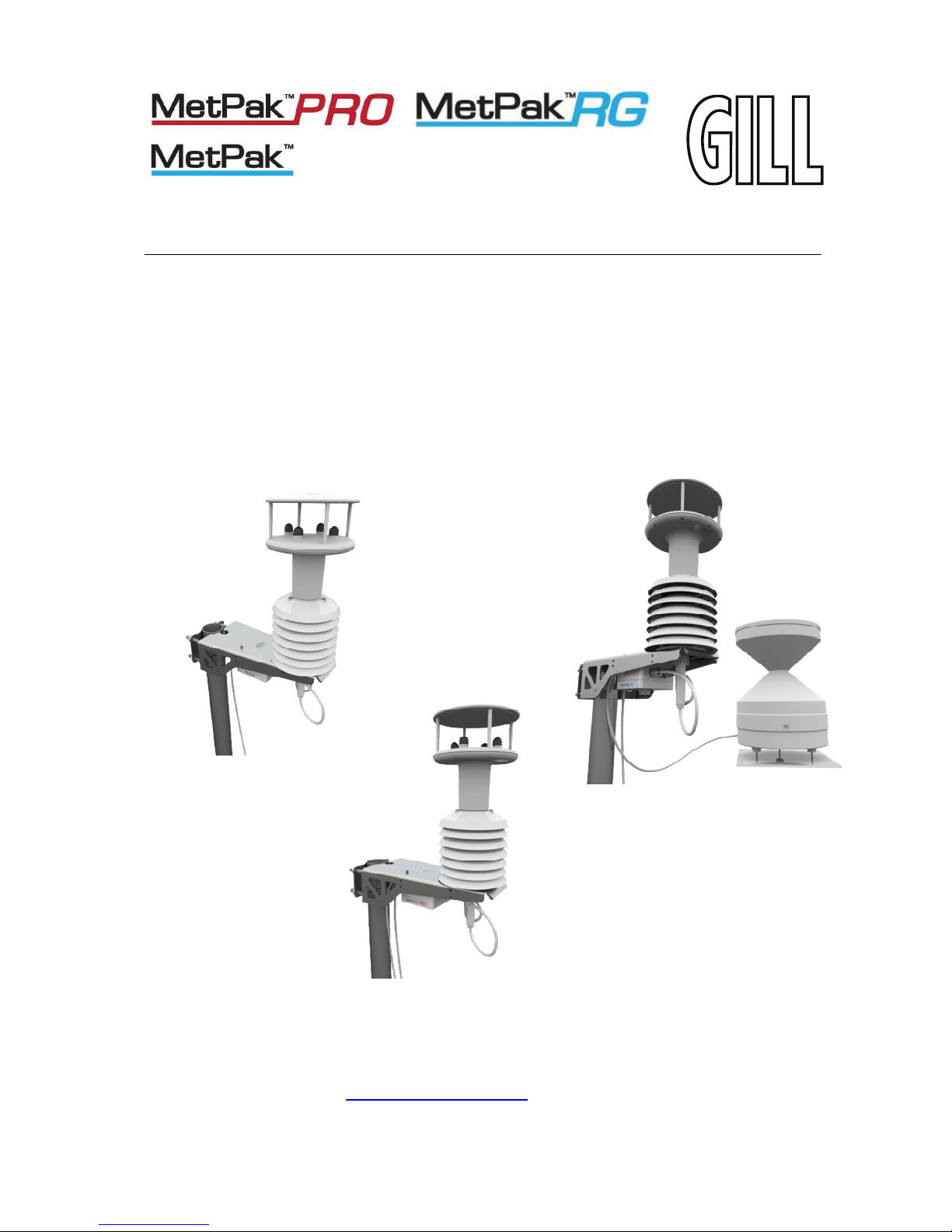
All the MetPak range equipments are Professional multi-sensor instruments that measure the most
essential weather parameters. They also provide a data collection system that allows customers to
add their own selection of sensors to meet local requirements. Gill ultrasonic technology, as used
in the proven WindSonic instrument, measures wind speed and direction. Temperature and
Humidity are measured and Dewpoint calculated using an industry standard probe housed in a
naturally aspirated radiation shield. Barometric pressure is measured using an industry standard
sensor.
The MetPak RG allows in addition for the customer to use an aerodynamic tipping bucket for Rain
measurements.
The MetPak Pro in addition allows the customer to add up to four additional sensors. One PRT
(temperature sensor), one digital (contact closure rain gauge) and two analogue inputs (4-20mA or
0-5V) e.g. water level sensor, Pyranometer, pressure sensor, soil temperature etc. Other types of
sensors may be added limited by the number of inputs available.
MetPak range units combines all the instrument data into a single combined data string. This may
be configured for digital ASCII RS232/RS422/RS485 (2 wire point to point), digital MODBUS
RTU/ASCII and SDI-12 outputs.
The instrument uses a rugged mounting clamp that attaches to any vertical pipe up from 30mm to
58mm diameter.
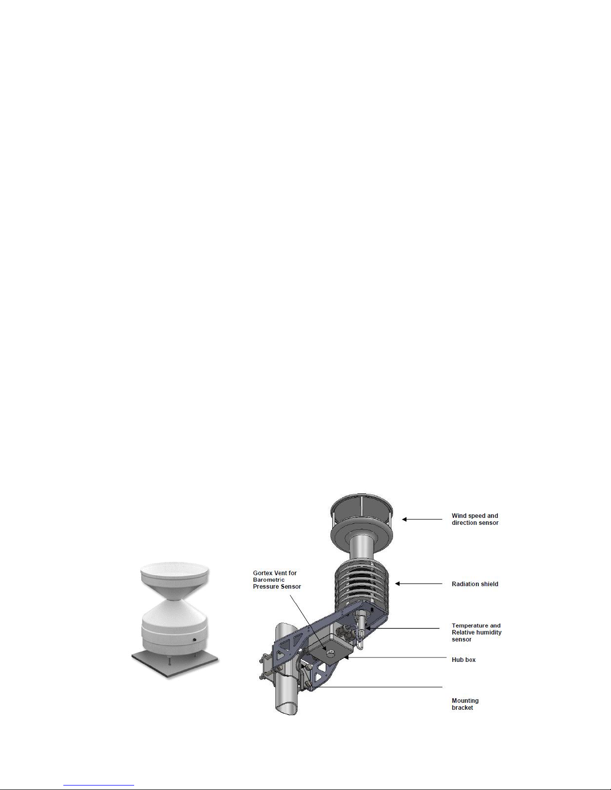
An electrical Hub box is fitted to the mounting bracket for termination of sensors limited to cable
gland entry, data and power cables. A separate Junction box is optionally available for easier
termination of external sensors, power and communication cables.
MetPak/MetPak RG/MetPak Pro
Page 5
Gill Instruments Ltd
_____________________________________________________________________________________________________________
________________________________________________________________________________________________
MetPak/MetPak RG and MetPak Pro Page | 5 Issue 1
Doc. No. 1723-PS-0022 October 2018
2.1. MetPak Part Numbers and Parameters
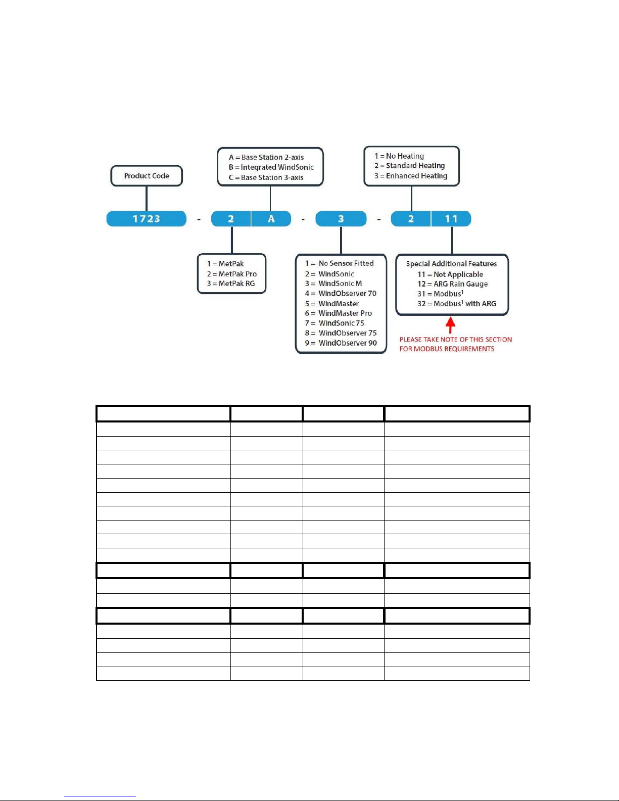
2.1.1. MetPak Part Number Structure.
2.1.2. MetPak Derived Parameters and Sensors.
MetPak Sensor Parameter MetPak MetPak RG MetPak Pro
Wind Speed, Relative
Yes Yes
Yes
Wind Direction, Relative
Yes Yes
Yes
Temperature, Air
Yes Yes
Yes
Humidity, Relative
Yes Yes
Yes
Dewpoint
Yes Yes
Yes
Barometric Pressure
Yes Yes
Yes
Rain/Precipitation No Yes Yes with user supply Rain Gauge
Temperature from a PRT
No
No Yes with user supply PRT
Analogue Sensor 1
No
No Yes with user supply Sensor
Analogue Sensor 2
No
No Yes with user supply Sensor
MetPak Derived Parameter
MetPak
MetPak RG
MetPak Pro
Status (Sensors)
Yes
Yes Yes
Volts (Supply) Yes Yes Yes
MetPak Outputs
MetPak
MetPak RG
MetPak Pro
Gill ASCII
Yes Yes Yes
Modbus
Yes Yes Yes
SDI-12
Yes Yes Yes
NMEA
Yes No No
Page 6
Gill Instruments Ltd
_____________________________________________________________________________________________________________
________________________________________________________________________________________________
MetPak/MetPak RG and MetPak Pro Page | 6 Issue 1
Doc. No. 1723-PS-0022 October 2018
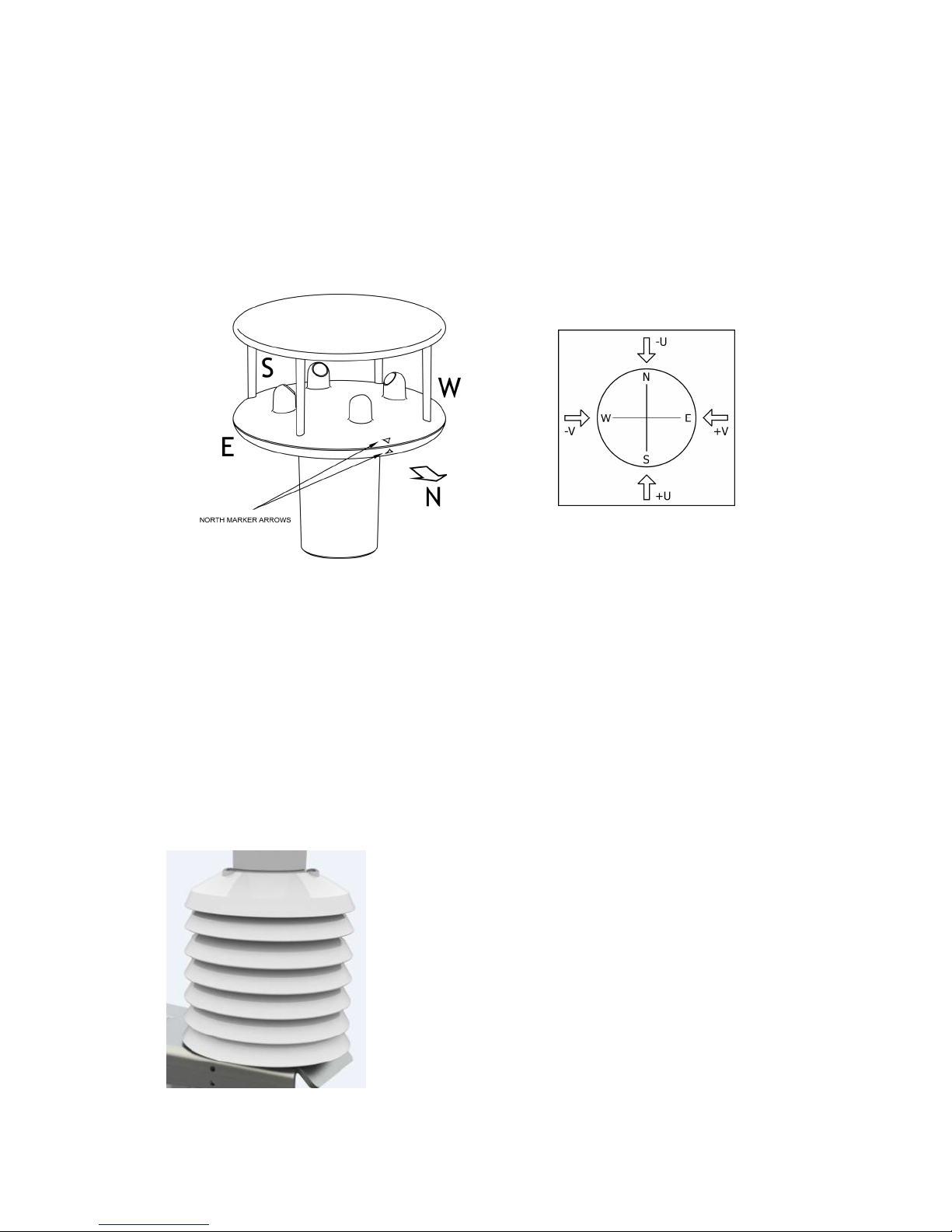
2.1.3. Wind Speed and Direction Sensor
The MetPak uses the Gill WindSonic wind speed and direction sensor. The WindSonic measures
the times taken for an ultrasonic pulse of sound to travel from the North (N) transducer to the
South (S) transducer, and compares it with the time for a pulse to travel from S to N transducer.
Likewise times are compared between West (W) and East (E), and E and W transducer.
If, for example, a North wind is blowing, then the time taken for the pulse to travel from N to S will
be faster than from S to N, whereas the W to E, and E to W times will be the same. The wind
speed and direction can then be calculated from the differences in the times of flight on each axis.
This calculation is independent of factors such as temperature.
Compass points
The compass point and polarity of U and V if the wind components along the U and V axis are
blowing in the direction of the respective arrows.
MetPak outputs Relative wind – wind speed and/or direction relative to the north marker, which
may not be facing north.
2.1.4. Radiation Shield
A MetSpec Multi-Plate Radiation Shield provides excellent
protection to the Rotronics temperature and relative humidity
sensor, shielding the probe from unwanted errors, especially
from secondary upward reflecting solar radiation and/or wind
blown precipitation/airborne contaminants. The special shield
plate geometry, with its double louvre design, provides excellent
response time performance of quick ambient temperature
changes while still working effectively as a baffle to stop larger
contaminants such as salt or dirt from reaching the Rotronics
probe. Due to the increased protection offered to the Rotronics
probe by the MetSpec shield, the maintenance cycle can be
extended. The shield benefits from very robust material choice
and extremely high UV protection requiring no maintenance. A
further benefit of the MetSpec shield design is that the measured
temperature is now even closer to reference temperature
measurements made using artificially aspirated motors without
the drawbacks of such systems (power and the maintenance of
moving parts).
Page 7
Gill Instruments Ltd
_____________________________________________________________________________________________________________
________________________________________________________________________________________________
MetPak/MetPak RG and MetPak Pro Page | 7 Issue 1
Doc. No. 1723-PS-0022 October 2018
2.1.5. Temperature, Relative Humidity and Dewpoint
The MetPak MetSpec shield contains a Rotronic Hygroclip module. It is a complete instrument,
with integrated temperature compensation. Calibration data is maintained within the integrated
electronics. It provides digital output signals for Relative Humidity, Temperature and Dewpoint.
2.1.6. Barometric Pressure
Barometric pressure output is provided by a solid-state device fitted on to the circuit board in the
MetPak Unit Hub box. Vent to atmosphere is via a Gore-Tex type filter which also protects the
pressure sensor from the effects of wind and rain.
2.1.7. Precipitation (Digital Input 1).
MetPak RG and MetPak Pro:-
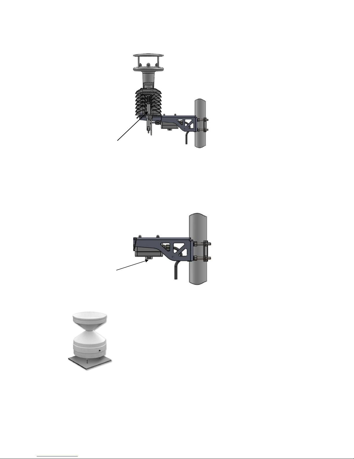
Rainfall is measured by the well-proven tipping bucket method. Rain is
collected by a funnel and is passed to one of the two buckets situated
at either end of a short balance arm. The balance arm tips when the
first bucket is full, emptying this bucket and positioning the second
bucket under the funnel. The tipping process repeats indefinitely as
long as the rain continues to fall, with each tip corresponding to a fixed
quantity of rainfall; at each tip the moving arm forces a magnet past a
reed switch, causing contact to be made for a few milliseconds.
An ARG100 Rain Gauge is supplied with a MetPak RG to connect to the Digital input (DIG1),
which detects when two dedicated terminals are short circuited (less than 1k ohm).
Rain levels are provided by reading the number of switch closures taking place over each output
rate time period (default one reading per second). Then multiplying this number by the Rain Gauge
count figure set using MetSet (e.g. 0.2mm per switch closure) and outputting the result in the data
string.
Hygroclip
Gore-Tex
type filter
Page 8

Gill Instruments Ltd
_____________________________________________________________________________________________________________
________________________________________________________________________________________________
MetPak/MetPak RG and MetPak Pro Page | 8 Issue 1
Doc. No. 1723-PS-0022 October 2018
2.1.8 PRT Temperature (PRT Input)
An external 2 or 4 wire PT100 device can be connected to a MetPak Pro to provide an additional
remote temperature measurement.
2.1.9 Analogue Sensor 1
An external remote analogue sensor, 0-5v/4-20mA output, can be connected to a MetPak
Pro AN1 input.
2.1.10 Analogue Sensor 2
An external remote analogue sensor, 0-5v/4-20mA output, can be connected to a MetPak
Pro AN2 input.
2.1.11 Status of MetPak Sensors
Outputs the MetPak Sensors Status Code (see para 8.3.2).
2.1.12 Supply Voltage
The DC Supply voltage measured at the MetPak unit is output in the MetPak Digital Data Output
string.
2.2. MetPak Sensors default ASCII Output Summary
MetPak Default Data String
Node, Relative Wind Direction, Relative Wind Speed, Pressure, Humidity, Temperature, Dewpoint,
Supply Voltage, Status, Checksum.
STX>Q,170,000.08,1019.5,035.0,+024.7,+008.3,+04.9,00,<ETX>55 & (CR,LF)
MetPak RG Default Data String
Node, Relative Wind Direction, Relative Wind Speed, Pressure, Humidity, Temperature, Dewpoint,
Digital Input 1, Supply Voltage, Status, Checksum.
<STX>Q,014,000.06,1011.2,042.1,+023.0,+009.4,0000.000,+04.9,00,<ETX>40 & (CR,LF)
MetPak Pro Default Data String
Node, Relative Wind Direction, Relative Wind Speed, Pressure, Humidity, Temperature, Dewpoint,
PRT, Analogue Input 1, Analogue Input 2, Digital Input 1, Supply Voltage, Status, Checksum.
<STX>Q,249,000.01,1017.3,049.2,+021.4,+010.3,+040.45,+000.06,+000.04,0000.000,+11.6,00,<
ETX>7C & (CR,LF)
Page 9

Gill Instruments Ltd
_____________________________________________________________________________________________________________
________________________________________________________________________________________________
MetPak/MetPak RG and MetPak Pro Page | 9 Issue 1
Doc. No. 1723-PS-0022 October 2018
3. TECHNICAL SPECIFICATION
Wind Measurement
Parameters Polar Wind Speed & Direction or U and V Vectors
Units of Measurement m/s, knots, mph, kph, ft/min
Wind Speed
Range 0.01 to 60m/s
Accuracy
2% @12m/s
Resolution 0.01m/s
Threshold 0.01m/s
Wind Direction
Range 0-359 Degrees – No dead band
Accuracy
3 @12 m/s
Resolution
1
Air Temperature
(Hygroclip)
Type Pt 100 1/3 Class B
Range
-35C to +70C
Accuracy
0.1C
Resolution
0.1C
Units of Measure
C or F
Relative Humidity
(Hygroclip)
Range 0-100%
Accuracy
0.8% @ 23C
Resolution 1%
Units of Measure % RH
Dew Point
Resolution
0.1C
Accuracy
0.15C (23C ambient temperature @ 20C dew point)
Units of Measure
C or F
Barometric Pressure
Range 600 to 1100hPa
Accuracy
0.5hPa
Resolution 0.1hPa
Units of Measure hPa, mbar, mmHg, InHg
Compensated for Temperature dependency –20C to +70C
Rain
with
ARG100
Rain Gauge
connected to MetPak RG
Precipitation Intensity 0 to 1000mm per hour.
Resolution 0.2mm/tip
Accuracy
2% (ARG100)
Units of Measure millimetres, inches per tip
Page 10

Gill Instruments Ltd
_____________________________________________________________________________________________________________
________________________________________________________________________________________________
MetPak/MetPak RG and MetPak Pro Page | 10 Issue 1
Doc. No. 1723-PS-0022 October 2018
Inputs
MetPak Pro (MetPak RG Digital Input only).
Analogue 1 (AN1) 0 to 5V or 4 to 20mA MetPak Pro powered or Analogue Sensor
Powered
Analogue 2 (AN2) 0 to 5V or 4 to 20mA MetPak Pro powered or Analogue Sensor
Powered
Analogue Input A-D
Conversion
12 bit resolution with an accuracy of 0.1% of reading, +35uV
offset (voltage inputs) or 0.5uA (current inputs).
Analogue Input Impedance Input impedance for 0-5v input is 330 k ohm.
Input impedance for 4-20mA input is 47 ohms.
PRT 4 wire PRT, Pt100 conforms to IEC 60751
Digital Input (DIG1)
Rain Gauge
Contact Closure input (tipping bucket rain gauge) capable of
capturing events up to 10Hz
Digital Input Capable of detecting an event with a duration of greater than
1.4mS.
Digital Input Capable of detecting a space between events (i.e. terminals
open-circuit) with a duration of greater than 11mS.
Digital Input Capable of reading a switch contact closure providing the total
Digital Switch contact resistance (contact and cabling) is less
than 1k ohm.
Outputs
Digital Outputs RS232, RS422, *RS485 (*2 wire point to point) or SDI-12.
(RS232 point to point and RS485 2 wire networkable –
MODBUS RTU/ASCII)
Baud Rates 1200 (SDI-12), 4800-57600 (ASCII RS232, RS422, *RS485)
9600-19200 (MODBUS RTU/ASCII)
Protocols ASCII, SDI-12 V1.3, NMEA 0183 (MetPak only) or MODBUS
RTU/ASCII
Data Output 1 reading per second (1 Hz), 1 reading per 2 seconds, 1
reading per 4 seconds or Polled Mode
MetPak Status Status codes provided within the data message string
*
RS485 2 wire point to point only.
Power Supply
Input voltage (RS232, RS422,
RS485)
4.5v to 30v dc
Current at 12v MetPak - 22mA
MetPak RG - 26mA
MetPak Pro - 26mA
Input Voltage SDI-12 9.6v to 16v dc (12v nominal)
Current MetPak - 30mA
MetPak RG - 35mA
MetPak Pro - 35mA
Page 11

Gill Instruments Ltd
_____________________________________________________________________________________________________________
________________________________________________________________________________________________
MetPak/MetPak RG and MetPak Pro Page | 11 Issue 1
Doc. No. 1723-PS-0022 October 2018
Environmental
MetPak Range
Protection Class IP65
EMC BS EN 61326
Operating Temperature
-35C to +70C
Storage Temperature
-40C to +80C
Humidity 0-100%
RoHS Compliant Yes
Environmental
ARG100 Rain Gauge
Protection Class Not applicable
EMC BS EN 61326
Operating Temperature
-35C to +70C
Storage Temperature
-40C to +80C
Humidity 0-100%
Mechanical
MetPak Range
External Construction UV Stabilised white thermoplastic (Wind Sensor and Hygroclip
Mountings) and anodized Aluminium bracket
Fittings
Overall Dimensions
MetPak
MetPak RG
MetPak Pro
364mmx287mmx142mm (excluding bracket clamp)
364mmx287mmx142mm (excluding bracket clamp)
364mmx287mmx142mm (excluding bracket clamp)
Weight
MetPak
MetPak RG
MetPak Pro
2.2kg (including bracket)
2.2kg (including bracket)
2.2kg (including bracket)
Mechanical ARG100
Rain Gaug
e
External Construction UV Resistant white thermoplastic
Fittings Rain Gauge Baseplate (RGB1) and 6 Metres of twisted pair
overall screened cable.
Overall Dimensions Funnel Diameter: 254mm (10.0 Inches)
Funnel Rim: 340mm (13.4 Inches)
Weight 1.0kg
Software
MetSet Configuration
MetView
Free PC Software providing the means of configuration of the
MetPak Unit.
Free PC Software providing the means of Viewing data and
providing a basic logging facility.
Page 12
Gill Instruments Ltd
_____________________________________________________________________________________________________________
________________________________________________________________________________________________
MetPak/MetPak RG and MetPak Pro Page | 12 Issue 1
Doc. No. 1723-PS-0022 October 2018
4. PRE-INSTALLATION
4.1. Equipment supplied
1723-xB-x-11x MetPak Variant unit
and 8 way connector inside the hub box for power and communication.
and Mounting bracket plate/nuts and bolts in a box.
and Tipping bucket rain gauge ARG100 with 6 Metre lead (MetPak RG only).
and MetPak Range User Manual and MetSetMetViewSoftware on a CD in the MetPak box
(this manual).
and Product Test Report.
4.1.1. Optional Extras:
Item Part Number
Barometric Pressure Hub Box Gore-Tex filter spares kit 1723-PK-024
Hygroclip Temperature and Humidity Filter Replacement Kit (two filters) 1723-PK-025
Hygroclip HC2-S3-GI
037-04263
Junction Box with internal terminating pcb (for MetPak Pro). 1723-PK-201
Rain Gauge. ARG100 Tipping bucket (no cable attached) 1723-PK-076
Terminating pcb (to mount in customer box) for MetPak Pro. 1723-PK-202
Pack of 4 brackets for Pole Mounting the Junction Box for MetPak Pro 1723-PK-203
Pack of 4 feet for Panel Mounting the Junction Box for MetPak Pro. 1723-PK-204
MetPak Range 1.8 Metre RS232 to USB converter including 5v dc power and
communication configuration cable (8 way MetPak connector fitted one end and
USB connector at the other end).
1723-10-051
Page 13

Gill Instruments Ltd
_____________________________________________________________________________________________________________
________________________________________________________________________________________________
MetPak/MetPak RG and MetPak Pro Page | 13 Issue 1
Doc. No. 1723-PS-0022 October 2018
4.2. Connector and Cable Assembly.
The MetPak is supplied with a mating 8 way connector for power and communication connections.
4.3. Communication Cabling
MetPak, MetPak RG and MetPak Pro have five communication connection options:
USB (using the 1.8m MetPak RS232 to USB cable, Part No. 1957-10-065).
RS232.
RS422.
RS485 (two wire point to point) or networkable if using Modbus.
SDI-12.
MetPak RG and MetPak Pro have a contact closure input connection:
DIG1 (Digital Switch).
MetPak Pro has in addition various Sensor Input connection options:
AN1 and AN2, Analogue inputs (0-5v or 4-20mA).
PRT. Platinum Resistance Thermometer Input.
It is important that the cable is appropriate for the chosen communication network. The following
sections describe the recommended types and maximum lengths of cable in each case.
4.3.1 Cable type
Wire type: 24 AWG
Wire size: 7x32 AWG.
Cable outer diameter: 6- 8mm (to match the connector gland).
For RS422/485 operation the cable should have twisted pairs with drain wire, screened with
aluminised tape, with an overall PVC sheath. Typical wire size 7/0.2mm (24 AWG).
The following table shows an example manufacturers’ reference; other manufacturers’ equivalents
can be used.
Recommended Belden cable types
Application No. of Pairs 24 AWG Belden Ref.
SDI-12 2
9729
Digital RS232 or RS485 3 9503
Digital RS422 4 9504
Multiple External Sensors 6 9506
Page 14

Gill Instruments Ltd
_____________________________________________________________________________________________________________
________________________________________________________________________________________________
MetPak/MetPak RG and MetPak Pro Page | 14 Issue 1
Doc. No. 1723-PS-0022 October 2018
4.3.2 Cable length
The maximum cable length is dependent on the chosen communication method.
The following table shows the maximum cable lengths for the supported communication protocols
at the given baud rates, using the recommended cable. If any problems of data corruption etc. are
experienced, then a slower baud rate should be used. Alternatively, a higher specification cable
can be tried.
Suggested maximum cable lengths for supported communication networks
Communication format Baud rate Max. cable length
RS232 19200
6.5M
RS422/485 19200 1000M
SDI-12 1200 90M
0-5v Analogue Input Not Applicable Refer to user Analogue Sensor data sheet
4-20mA Analogue Input Not Applicable Refer to user Analogue Sensor data sheet
Digital Switch Input
Not Applicable
Switch contact and cable resistance to be less
than 1k ohm
PRT Input Not Applicable Refer to user PRT data sheet
4.4. Cable Connections General
Any cable wires not used should be isolated and grounded at the terminating equipment/user end.
Digital OV should be used in conjunction with RS422 TX/RX lines in order to improve noise
immunity.
The Cable should be secured:-
With cable clamps or equivalent at regular intervals such that the hub box cable gland
does not support the cable weight.
Away from the mounting bolts to prevent chaffing of the cable.
NOTES:-
Install appropriate strain relief support to the cable. If possible, pass the cable through the
mounting pole.
The MetPak unit Hub Box cable glands contain spring loaded metal leaves that are designed to
make a ground contact with cables that have an overall braid screen. Care is therefore required
when inserting and removing cables through the glands to prevent damage to the metal leaves.
4.5. Earthing
To ensure correct operation and for maximum protection from lightning, a separate lightning rod
system is recommended to protect the system.
You can also earth the MetPak through its mountings or by connecting a grounding cable
(minimum of 6mm² copper wire) to a spare MetPak metalwork bolt hole. Clean off any paint that
might prevent a good connection.
When you connect the communications cable ensure that the screen has a connection to the hub
box case.
The Junction Box accessory has a plastic case, hence ensure continuity of cable screens into and
out of the Junction Box using the common Earthing terminals provided in the box.
Page 15
Gill Instruments Ltd
_____________________________________________________________________________________________________________
________________________________________________________________________________________________
MetPak/MetPak RG and MetPak Pro Page | 15 Issue 1
Doc. No. 1723-PS-0022 October 2018
WindSonic J4 Pin 1
4.6. Power supplies
Supply Voltage: 4.5v to 30v DC.
Average Current at 12v dc:-
MetPak 22mA.
MetPak RG 26mA.
MetPak Pro 26mA.
MetPak Units have reverse voltage polarity protection.
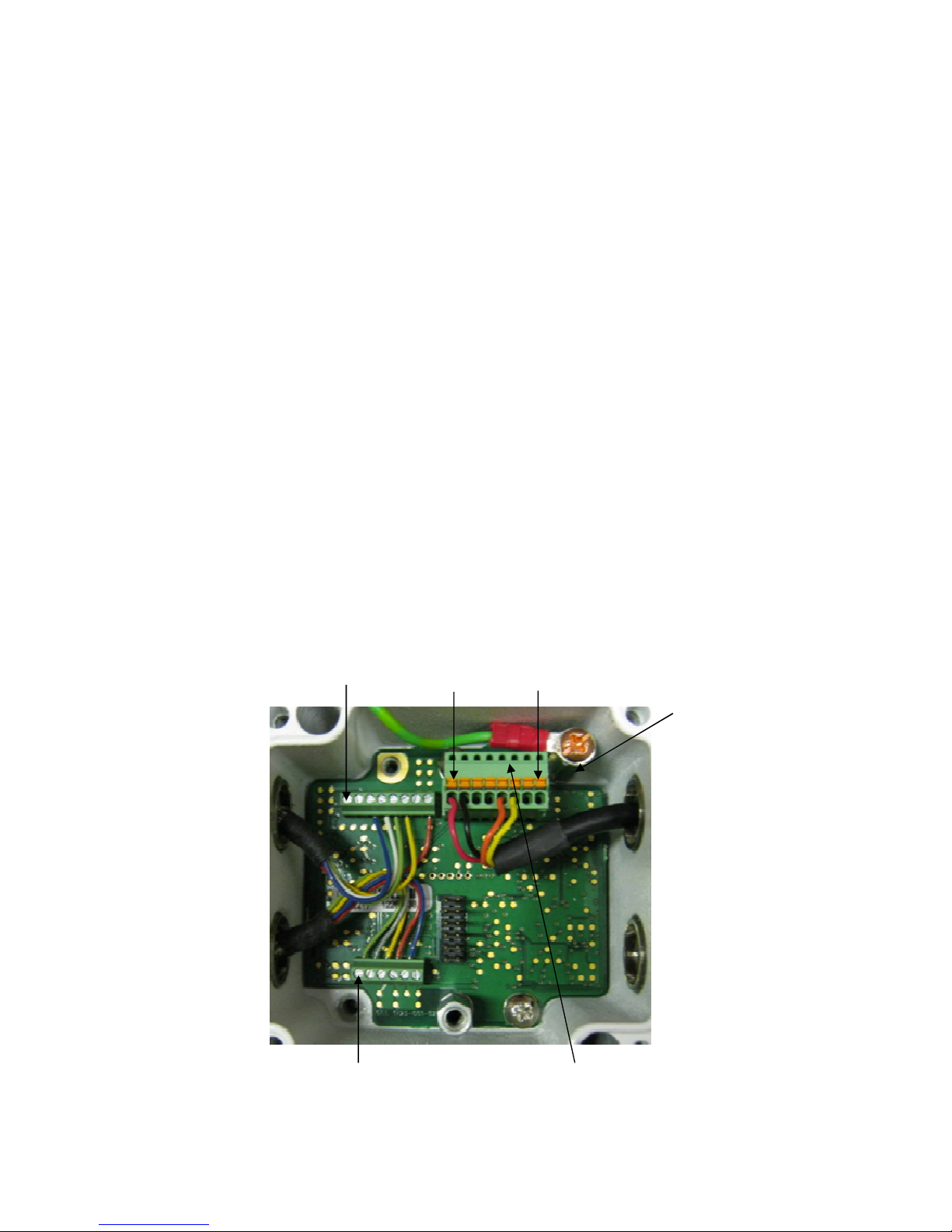
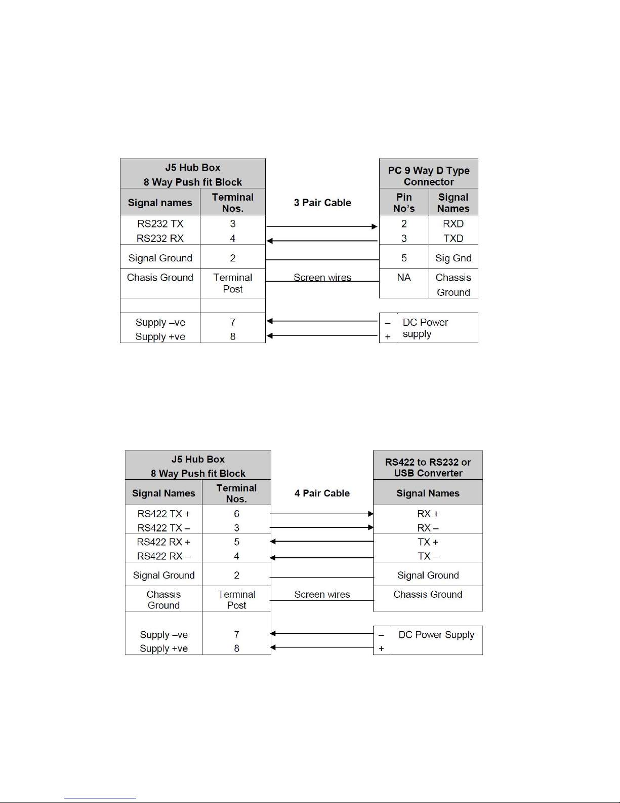
4.7. Power and Communication Connections
To connect Power and Communication to the MetPak Range:
Open MetPak hub box by unfastening the four screws.
Strip the power and communication cable wires to have 8mm of exposed soldered wire.
Pass the cable through one of the gland nuts (please refer to para 4.4. Notes).
Locate the green 8 way plug in connector J5 (see below).
Connect the cable to J5 for the required communication type e.g. RS232, RS422 etc.
Attach the cable’s screen wires to the Hex terminal post (see below).
After connection, securely tighten the gland nut to prevent moisture ingress.
NOTE: The MetPak Range Hub Box cable glands contain spring loaded metal leaves that are
designed to make a ground contact with cables that have an overall braid screen. Care is therefore
required when inserting and removing cables through the glands to prevent damage to the metal
leaves.
Re-fit the Hub box lid.
J5 Pin 8
J5 Pin 1
Hex
Terminal
Post
Hygroclip J1 Pin 6
J5, RS232 to USB and Power
Configuration Cable Wires
Page 16
Gill Instruments Ltd
_____________________________________________________________________________________________________________
________________________________________________________________________________________________
MetPak/MetPak RG and MetPak Pro Page | 16 Issue 1
Doc. No. 1723-PS-0022 October 2018
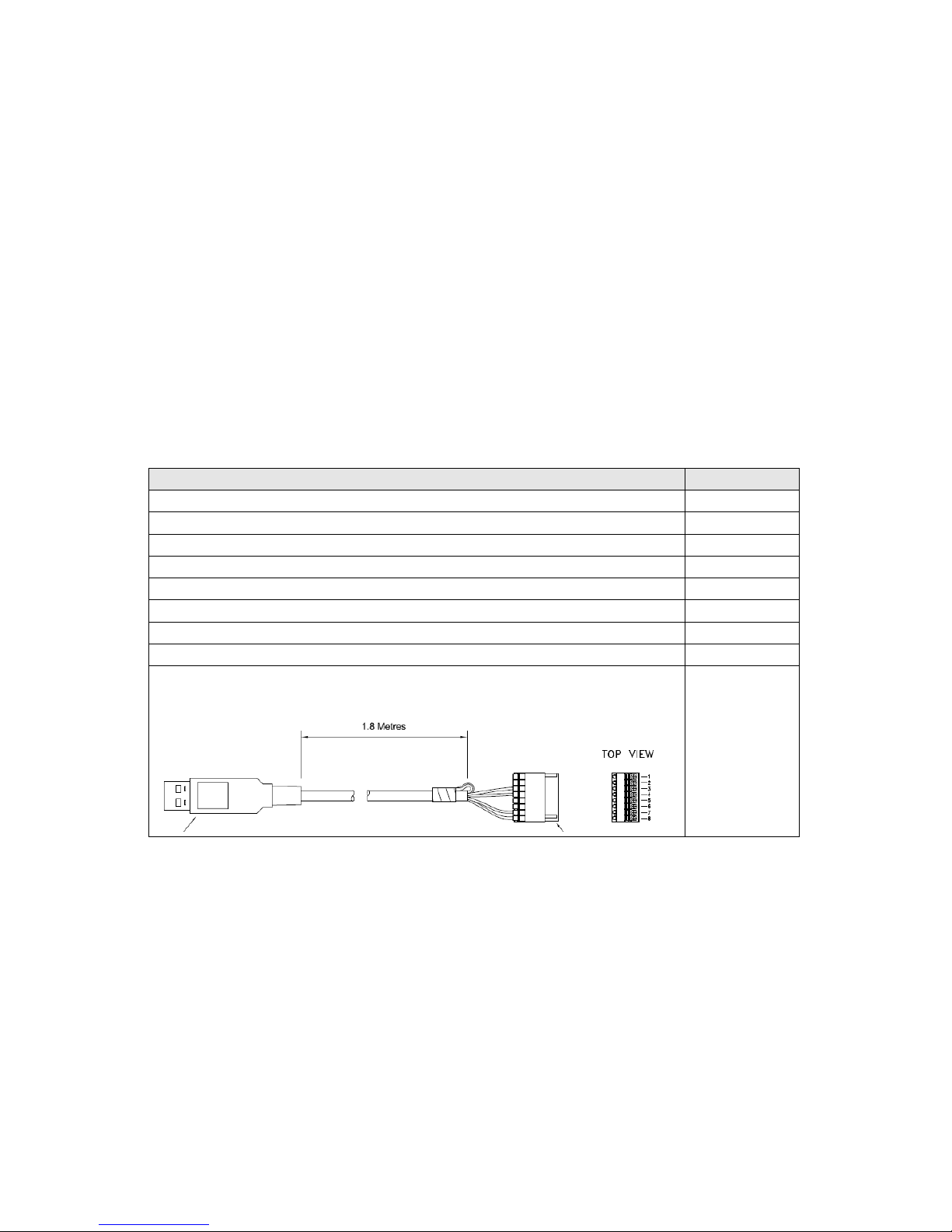
4.8. Connecting to a PC using Gill RS232 to USB Configuration Cable
Connect MetPak to a PC USB port using the Gill Configuration Cable 1723-10-051.
J5 Pin 1 2 3 4 5 6 7 8
Colour None None Yellow Orange None None Black Red
Connection of Gill USB Cable (Part No. 1723-10-051), the J5, 8way Phoenix connector part
number is 1881383.
NOTES:- If upon connecting the USB lead to a PC the driver is not found by the PC, then the
appropriate driver to match the PC Windows version may be downloaded from:-
http://www.ftdichip.com/Drivers/VCP.htm
Page 17

Gill Instruments Ltd
_____________________________________________________________________________________________________________
________________________________________________________________________________________________
MetPak/MetPak RG and MetPak Pro Page | 17 Issue 1
Doc. No. 1723-PS-0022 October 2018
Hub Box Factory Connections
Hygroclip connections (6-way connector J1)
WindSonic anemometer connections (8-way connector J4)
Hub Box User Connections
Power and Communications (8-way connector, J5) all units
Connector J1
Wire Colour
Signal Name
1 - No Connection
2 Blue RXD from Hygroclip UART
3 Red TXD to Hygroclip UART
4 Yellow Analogue 0V (Not Used)
5 Grey Supply/Signal 0V
6 Green Supply +ve (+3.3V DC)
Connector J4
Wire Colour
Signal Name
1 - No Connection
2 - No Connection
3
Blue
RS232 TX+ Anemometer Output to
Hub
4
White
RS232 RX+ Hub Output to
Anemometer
5 Green Signal 0v
6 Yellow Supply 0v
7 - No Connection
8 Red Supply +ve (4.5v to 30V dc)
Connector J5
Signal Name
1 SDI-12 TX/RX
2 Signal 0V
3
RS232 TX
-
, (or RS422/RS485 TX
-
) HUB to user
4
RS232 RX
-
, (or RS422 RX
-
) User to HUB
5
RS422 RX+, User to HUB
6 RS422/RS485 TX+, HUB to User
7
Supply 0v
8 Supply
+ve (4.5v to 30v dc)
Page 18

Gill Instruments Ltd
_____________________________________________________________________________________________________________
________________________________________________________________________________________________
MetPak/MetPak RG and MetPak Pro Page | 18 Issue 1
Doc. No. 1723-PS-0022 October 2018
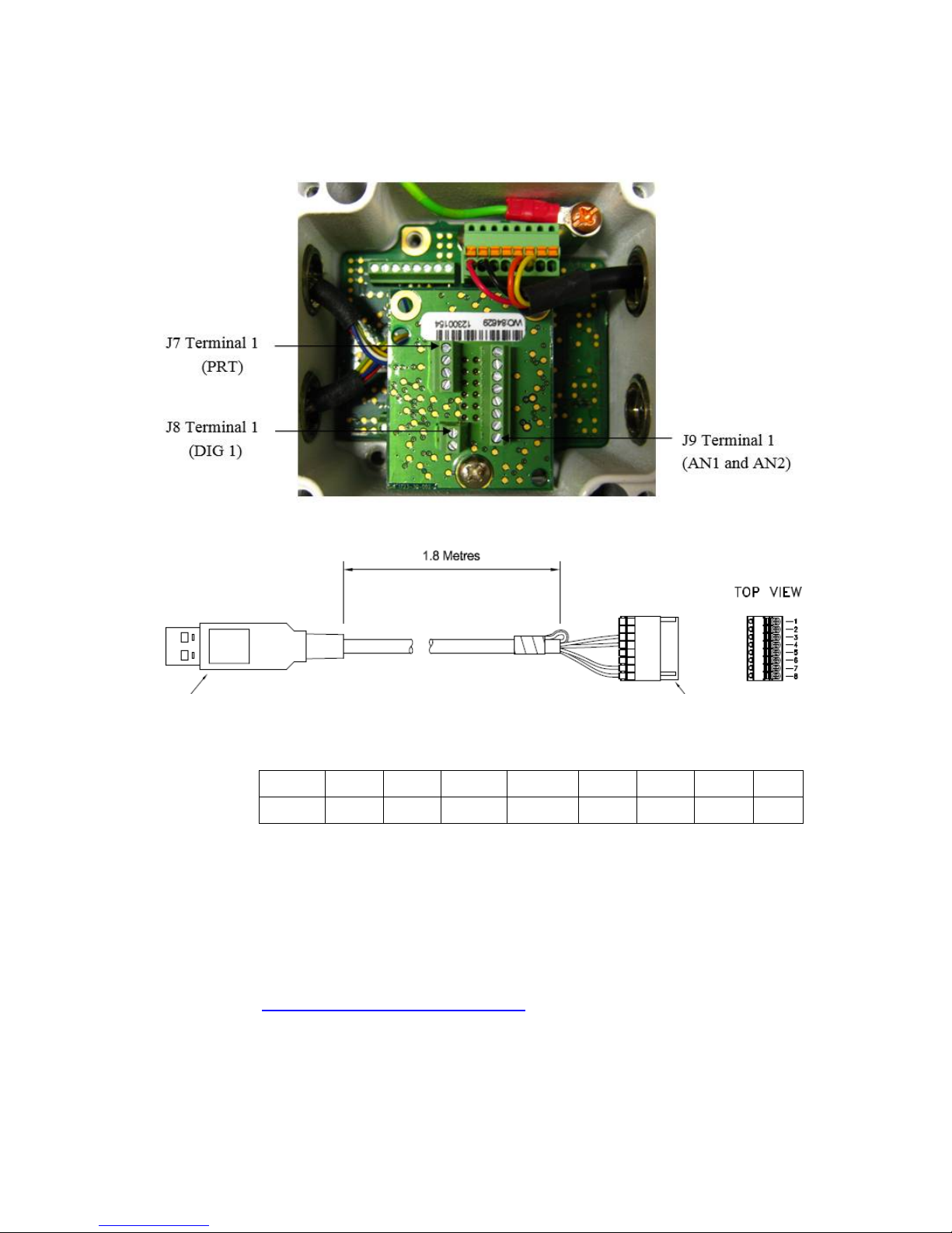
MetPak Pro PRT Sensor (4-way connector, J7)
MetPak RG and MetPak Pro Digital Switch Input, DIG1 (2-way connector, J8)
MetPak Pro Analogue Sensors Input, AN1 and AN2 (8-way connector, J9)
Connector J7
Signal Name
1 PWR (PRT Power Supply +ve)
2 PRT +
3 PRT 4 GND (PRT Power Supply Ground)
Connector J8
Signal Name
2 DIG1 (Digital Switch Contact Input)
1 GND (Ground)
Connector J9
Signal Name
1 VI 1 (Voltage Input 1)
2 GND (Voltage Input 1 Ground)
3 VI 2 (Voltage Input 2)
4 GND (Voltage Input 2 Ground)
5
II PWR (Current Supply for Analogue Input 1)
6 II 1 (Analogue Input 1)
7 II PWR (current Supply for Analogue Input 2)
8 II 2 (Analogue Input 2)
Page 19
Gill Instruments Ltd
_____________________________________________________________________________________________________________
________________________________________________________________________________________________
MetPak/MetPak RG and MetPak Pro Page | 19 Issue 1
Doc. No. 1723-PS-0022 October 2018
4.9. Connecting to a PC using RS232 (Default setting)
1. MetPak Range default factory comms setting is RS232.
2. The recommended cable length for reliable operation is limited to 6.5m (20ft).
3. For longer cable runs, we recommend use of RS422 output.
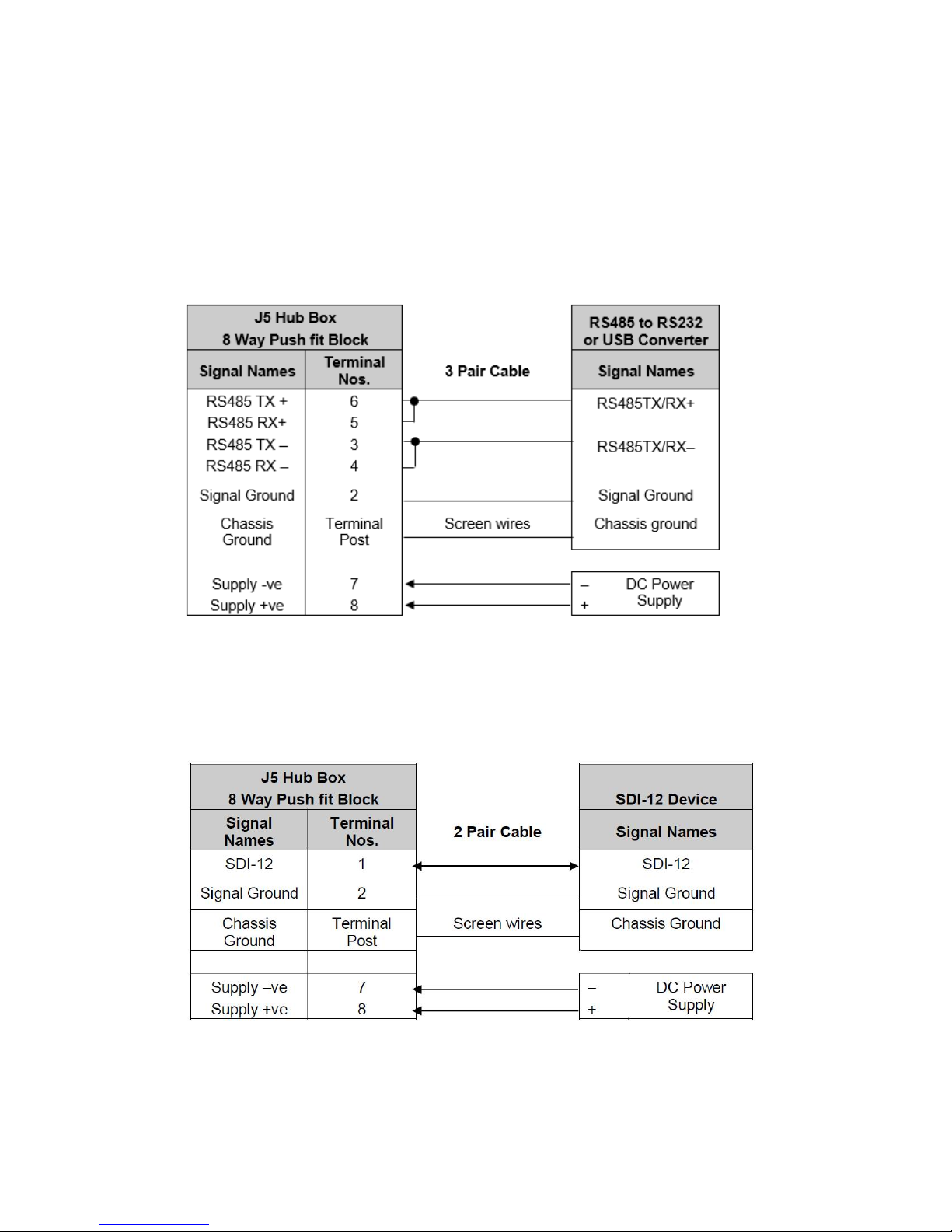
4.10. Connecting to a PC using RS422 (Not a Default Setting)
1. MetPak Range default factory comms setting is RS232.
2. To use the MetPak Range with RS422 comms use MetSet to change the COMMS
Interface setting to RS422.
Page 20
Gill Instruments Ltd
_____________________________________________________________________________________________________________
________________________________________________________________________________________________
MetPak/MetPak RG and MetPak Pro Page | 20 Issue 1
Doc. No. 1723-PS-0022 October 2018
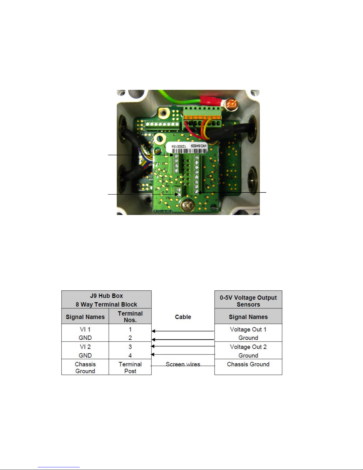
4.11. Using RS485 (2 wire point to point only, not a default setting.
1. MetPak Range default factory comms setting is RS232.
2. To use the MetPak Range with RS485 2 wire point to point communication use MetSet to
change the COMMS Interface setting to RS485P 2W.
3. Use MetSet to change the Message setting from CONT (Continuous) to POLL, the node
address letter may be changed if required.
4. Note that it is not possible to network other devices on this 2-wire RS485 link unless the
unit has been set for Modbus operation and application.
4.12. Using SDI-12 (2 wire network) not a default setting.
1. MetPak Range default factory comms setting is RS232.
2. Use MetSet to change the COMMS Interface setting to SDI 12.
Page 21
Gill Instruments Ltd
_____________________________________________________________________________________________________________
________________________________________________________________________________________________
MetPak/MetPak RG and MetPak Pro Page | 21 Issue 1
Doc. No. 1723-PS-0022 October 2018
J9 Terminal 1
(AN1 and AN2)
4.13. Analogue, Digital and PRT Input Connections
NOTE:
MetPak - This section is Not Applicable.
MetPak RG - Digital input connection applicable only.
MetPak Pro - Analogue, Digital and PRT Input connections all applicable.
Analogue 0-5 volt Input Connections AN1 and AN2
This is not a default setting; ensure the MetPak Pro has been configured for this input requirement
before wiring sensors to the MetPak Pro.
(See picture above for Power and Communication Connections).
J8 Terminal 1
(DIG 1)
J7 Terminal 1
(PRT)
Page 22
Gill Instruments Ltd
_____________________________________________________________________________________________________________
________________________________________________________________________________________________
MetPak/MetPak RG and MetPak Pro Page | 22 Issue 1
Doc. No. 1723-PS-0022 October 2018
Analogue 4-20mA Input Connections (Sensor Powered) AN1 and AN2
This is not a default setting; ensure the MetPak Pro has been configured for this input requirement
before wiring sensors to the MetPak Pro.
See picture above for Power and Communication Connections.
Analogue 4-20mA Input Connections (MetPak Pro Powered) AN1 and AN2
This is not a default setting; ensure the MetPak Pro has been configured for this input requirement
before wiring sensors to the MetPak Pro.
See picture above for Power and Communication Connections.
NOTE: If the input current drops below 4mA, an X will be shown in the data string instead of
a valid reading. If the current rises above 20mA, an E will be shown in the data string
instead of a valid reading.
Page 23
Gill Instruments Ltd
_____________________________________________________________________________________________________________
________________________________________________________________________________________________
MetPak/MetPak RG and MetPak Pro Page | 23 Issue 1
Doc. No. 1723-PS-0022 October 2018
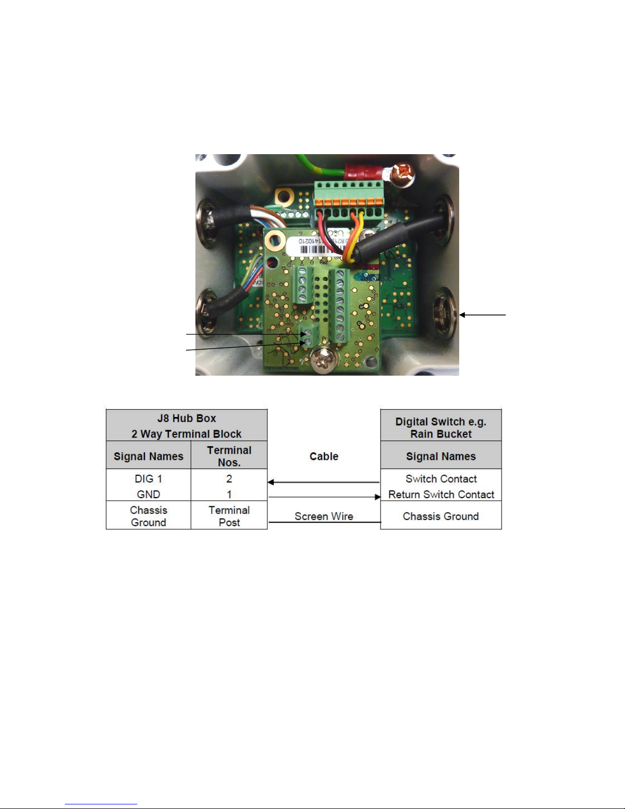
Digital Switch Connection (Rain Gauge) DIG1
Ensure the MetPak RG/MetPak Pro has been configured for this input requirement before wiring
sensors to the Unit.
Digital Rain Gauge Connections
To connect the MetPak RG ARG100 Rain Gauge 6 Metre lead to the Hub Box or another rain
gauge wiring.
1. Open the MetPak hub box by unfastening the four screws.
2. Locate connector J8.
3. Pass the cable through one of the gland nuts (see Note below).
4. Connect the cable to connections as detailed above.
5. Attach the cable’s screen wire to a terminal post.
6. After connection, securely tighten the gland nut to prevent moisture ingress.
7. Re-fit the hub box lid.
NOTE: The MetPak Range Hub Box cable glands contain spring loaded metal leaves that are
designed to make a ground contact with cables that have an overall braid screen. Care is therefore
required when inserting and removing cables through the glands to prevent damage to the metal
leaves.
J8 Terminal 2
J8 Terminal 1
Rain Gauge
Cable Entry
Gland.
Rain Gauge
Connections
Page 24
Gill Instruments Ltd
_____________________________________________________________________________________________________________
________________________________________________________________________________________________
MetPak/MetPak RG and MetPak Pro Page | 24 Issue 1
Doc. No. 1723-PS-0022 October 2018
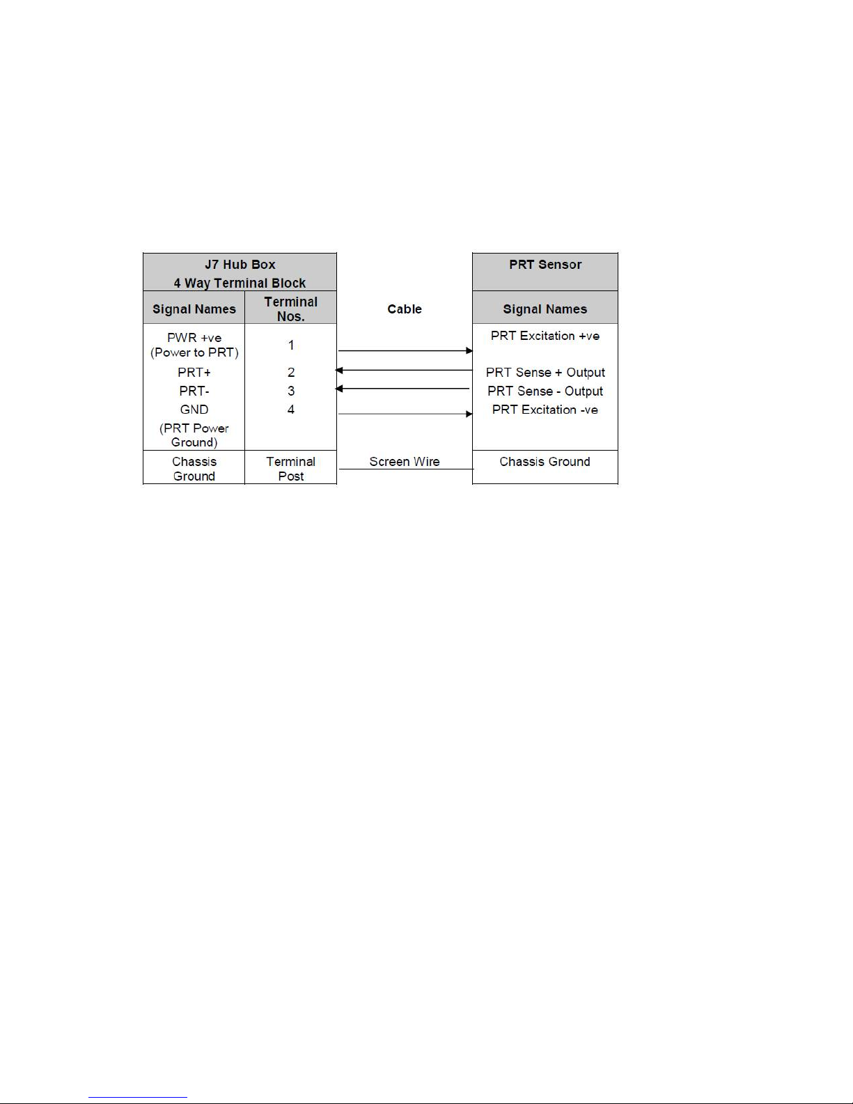
Platinum Resistance Thermometer (PRT) Input
This is not a default setting; ensure the MetPak Pro has been configured for this input requirement
before wiring sensors to the MetPak Pro.
See the previous picture for Power and Communication Connections.
Page 25
Gill Instruments Ltd
_____________________________________________________________________________________________________________
________________________________________________________________________________________________
MetPak/MetPak RG and MetPak Pro Page | 25 Issue 1
Doc. No. 1723-PS-0022 October 2018
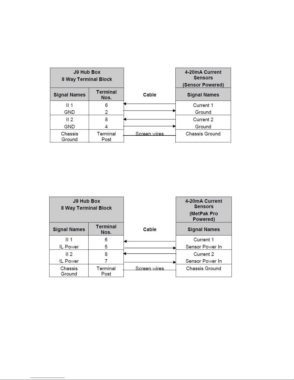
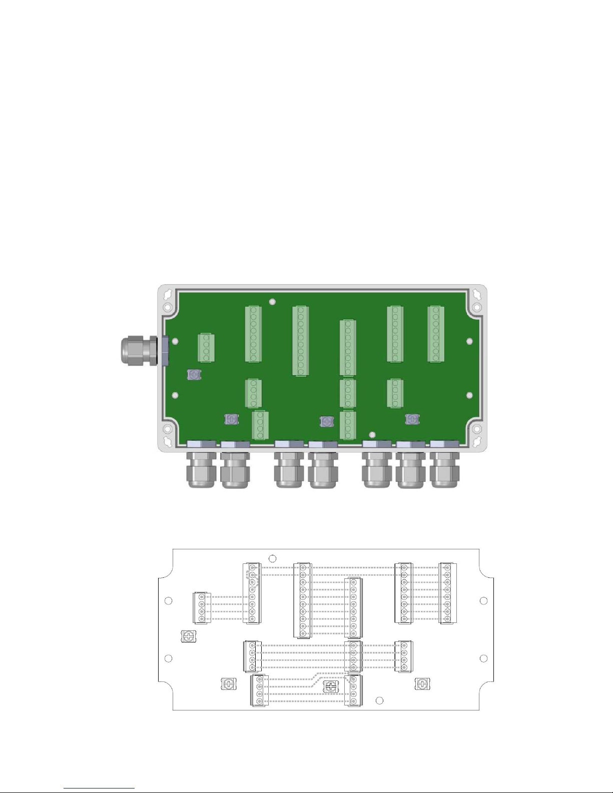
4.14. MetPak Pro Junction Box (Part 1723-PK-021)
As part of a MetPak Pro system, Gill Instruments can provide a Junction Box containing a pcb with
removable terminal connectors and optional mounting hardware to provide a means of connecting
external sensor and MetPak Pro wiring at a convenient common point.
Alternatively the pcb with removable terminal connectors can be supplied as a standalone item for
mounting in a customer supplied box.
Junction Box parts if required are:
1723-PK-201 Junction Box with internal terminating pcb.
1723-PK-202 Terminating pcb (to mount in customer box).
1723-PK-204 Pack of 4 feet for Panel Mounting the Junction Box.
1723-PK-203 Pack of 4 brackets for Pole Mounting the Junction Box.
Junction Box 1723-PK-201 (containing Terminating pcb 1723-PK-202)
Junction Box terminating pcb circuit track layout
Page 26
Gill Instruments Ltd
_____________________________________________________________________________________________________________
________________________________________________________________________________________________
MetPak/MetPak RG and MetPak Pro Page | 26 Issue 1
Doc. No. 1723-PS-0022 October 2018
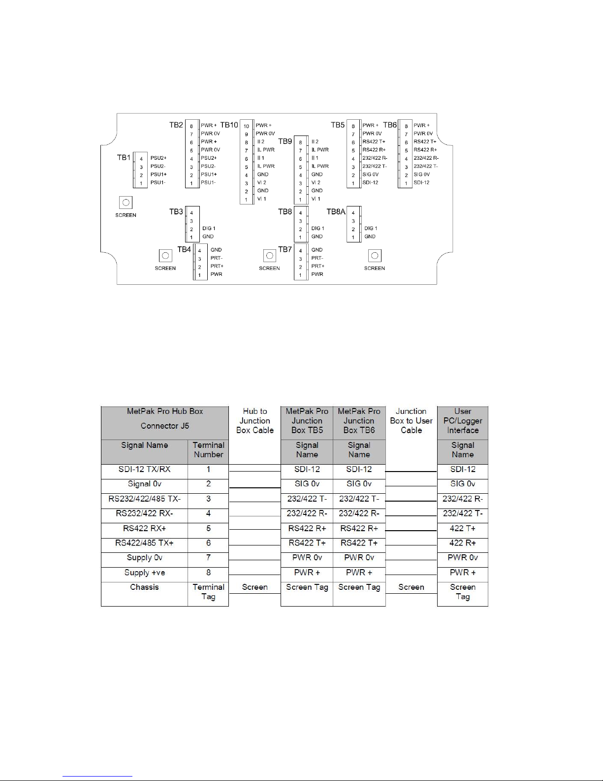
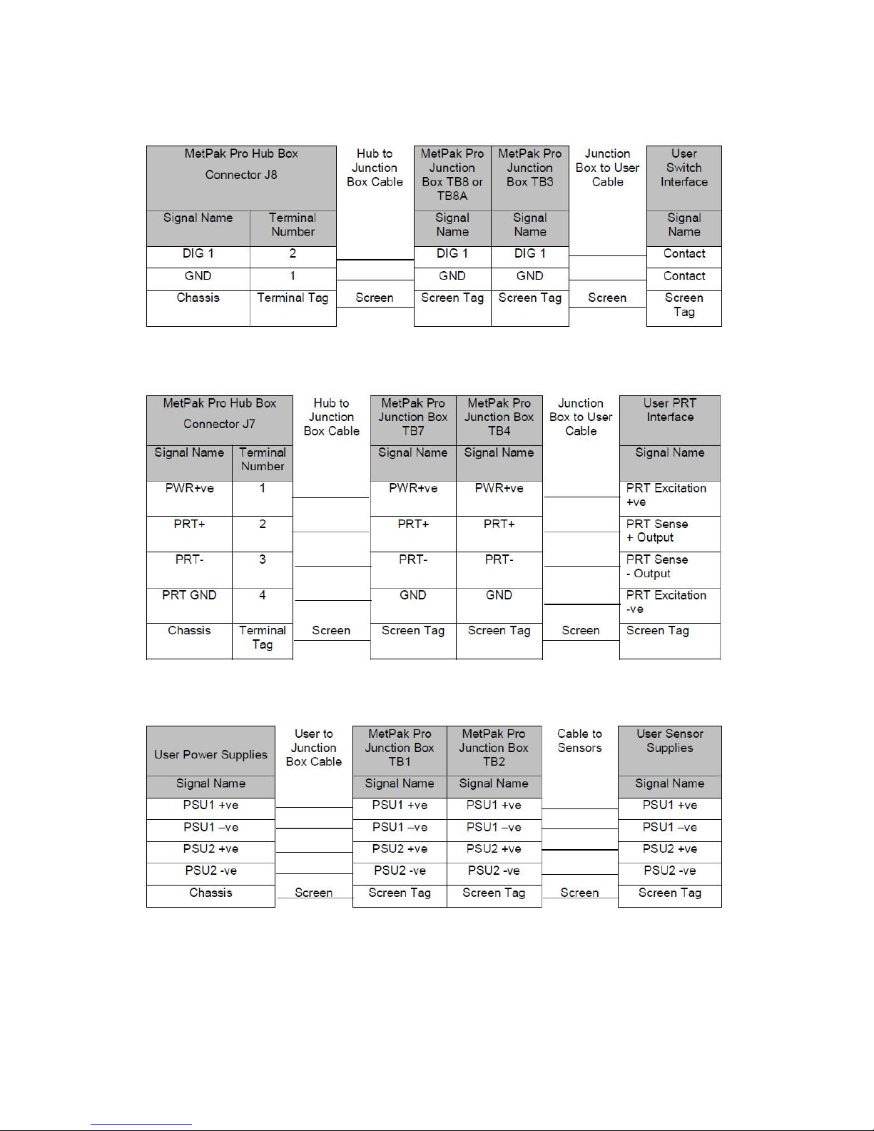
Junction Box Terminal Block Connections
Note that the Junction box glands will accept cables with an outer diameter between 3-10mm. If a
smaller diameter cable is to be used bulk out with heat shrink or suitable sleeve to ensure the
gland can secure the cable and provide an environmental seal.
Communication System Connections
Only connect cables that meet the required data interface requirement (e.g. RS232 etc.).
Page 27

Gill Instruments Ltd
_____________________________________________________________________________________________________________
________________________________________________________________________________________________
MetPak/MetPak RG and MetPak Pro Page | 27 Issue 1
Doc. No. 1723-PS-0022 October 2018
4-20mA Current Sensor System Connections (Sensor Powered)
4-20mA Current Sensor System Connections (MetPak Pro Powered)
0-5 Volt Voltage Sensor System Connections
Page 28
Gill Instruments Ltd
_____________________________________________________________________________________________________________
________________________________________________________________________________________________
MetPak/MetPak RG and MetPak Pro Page | 28 Issue 1
Doc. No. 1723-PS-0022 October 2018
Digital Switch Sensor System Connections
PRT System Connections
External Power Supply Connections
Page 29

Gill Instruments Ltd
_____________________________________________________________________________________________________________
________________________________________________________________________________________________
MetPak/MetPak RG and MetPak Pro Page | 29 Issue 1
Doc. No. 1723-PS-0022 October 2018
4.15. Set up requirements
4.15.1. Host System:
Note: The default delivery output communication (COMMS) setting of MetPak units is RS232.
Use an RS232 to USB converter e.g. Gill part 1957-10-065, 1.8M configuration cable fitted with 8
way Hub Box connector and with integral 5v USB connector power for MetPak (see Para 4.8).
If an install driver is required for this cable it can be obtained from the supplied CD or downloaded
from:-
http://www.ftdichip.com/FTDrivers.htm
Or
Use an RS232 to USB adaptor or equivalent for example EasySynch part ES-U-1001-A (if not
using Gill part 1957-10-065) or connect directly to an RS232 COM port.
Use a PC running Windows software up to and including Windows 10 and with an internal or
external interface compatible with the output from the MetPak.
Use a Power Supply, 5V to 30Vdc at 200mA if not using the Gill Instruments Configuration cable.
Use 3 pair cable e.g. Belden 9503 (if not using Gill Part 1723-10-051), length as required if not
using the Gill Instruments Configuration cable.
4.15.2. Software:
Gill MetSet Software used as a configuration Tool (supplied on MetPak CD), will run on PC’s with
up to and including Windows 10 and can be downloaded free from:-
http://www.gillinstruments.com/main/software.html.
4.15.3. Bench system test
The CD supplied in the MetPak box contains a copy of the manual and relevant software to check
and set up the MetPak unit.
Prior to physically mounting the MetPak in its final location, we strongly recommend that a bench
system test be carried out to confirm the system is configured correctly, is fully functional and
electrically compatible with the selected host system and cabling (preferably utilising the final cable
length). The required data format, units, output rate, and other options should also all be
configured at this stage.
Connect the MetPak to a PC wired as per RS232 connections in Para 4.9.
Alternatively use a Gill configuration cable part 1957-10-065 with a 9 way connector fitted on one
end and USB converter at the other end if required to simplify set up between MetPak and a PC.
Open Gill MetSet software provided to read, check settings or change settings as per para 6.2.
Use MetSet View Output button to check the data string and confirm that the Status field reads 00.
4.16. Packaging
Whilst the MetPak is being moved to its installation site, the unit should be kept in its packaging.
Retain the packaging for use if the unit has to be moved or returned to Gill Instruments.
Page 30

Gill Instruments Ltd
_____________________________________________________________________________________________________________
________________________________________________________________________________________________
MetPak/MetPak RG and MetPak Pro Page | 30 Issue 1
Doc. No. 1723-PS-0022 October 2018
5. INSTALLATION
General Installation Guidelines are as follows:-
5.1. Example Installation Guidelines
5.1.1. Non Heated Wind Sensor System
MetPak Pro System Connections - A Typical MetPak Pro system might look like the following
illustration.
Page 31

Gill Instruments Ltd
_____________________________________________________________________________________________________________
________________________________________________________________________________________________
MetPak/MetPak RG and MetPak Pro Page | 31 Issue 1
Doc. No. 1723-PS-0022 October 2018
5.2. Interference
As with any sophisticated electronics, good engineering practice should be followed to ensure
correct operation.
Always check the installation to ensure the MetPak is not affected by other equipment operating
locally, which may not conform to current standards, e.g. radio/radar transmitters, boat engines,
generators etc.
Do NOT mount the MetPak in close proximity of high-powered radar or radio transmitters. A site
survey may be required if there is any doubt about the strength of external electrical noise.
Guidelines –
Avoid mounting in the plane of any radar scanner – a vertical separation of at least 2m should be
achieved.
Radio transmitting antennas, the following minimum separations (all round) are suggested
VHF IMM – 1m
MF/HF – 5m
Satcom – 5m (avoid likely lines of sight)
Ensure the product is correctly earthed in accordance with this manual.
Use cables recommended by Gill, keeping the length below the maximum allowed. Where the
cables are cut and re-connected (junction boxes, plugs and sockets) the cable screen integrity
must be maintained, to prevent the EMC performance being compromised.
Earth loops should not be created – earth the system in accordance with the installation
guidelines.
Ensure the power supply operates to the MetPak specification at all times.
5.3. Wind Sensor Installation
Avoid turbulence caused by surrounding structures that will affect the accuracy of the MetPak such
as trees, masts and buildings.
The World Meteorological Organisation makes the following recommendation:
The standard exposure of wind instruments over level open terrain is 10m above the ground.
Open terrain is defined as an area where the distance between the sensor and any
obstruction is at least 10 times the height of the obstruction.
If mounting on a building then theoretically the sensor should be mounted at a height of 1.5
times the height of the building.
If the sensor is to be mounted on a mast boom, part way up a tower or mast, then the boom
should be at least twice as long as the minimum diameter or diagonal of the tower. The boom
should be positioned on the prevailing wind side of the tower.
It is important to ensure that the MetPak is mounted in a position clear of any structure, which may
obstruct the airflow or induce turbulence.
Mount MetPak so as to have a clear view of prevailing winds.
The MetPak anemometer should be set to point North (or to another known reference direction),
using the North Pointers, which are identified by two arrows, a coloured rectangle, and an
alignment notch to aid alignment (see the illustration in para 2.1.3).
Page 32

Gill Instruments Ltd
_____________________________________________________________________________________________________________
________________________________________________________________________________________________
MetPak/MetPak RG and MetPak Pro Page | 32 Issue 1
Doc. No. 1723-PS-0022 October 2018
5.4. MetPak Range Mounting and Dimensions (in mm)
MetPak uses a mounting clamp suitable for attaching to a vertical pipe with a diameter of 3058mm. When mounting the MetPak, consider the position, orientation and alignment of the unit.
Note that the mounting pipe should first be degreased and when assembling the MetPak clamp
assembly the outer clamp nuts need to be tightened evenly to a torque figure of 3 Nm.
The moving plate part of the clamp needs to be reversed for poles below 38 mm diameter.
Mounting Bracket Assembly Exploded View
Mounting Bracket Assembled View
C Holes are 8.5mm diameter
Earthing Point for
supplied
screw/washer/tag
Page 33

Gill Instruments Ltd
_____________________________________________________________________________________________________________
________________________________________________________________________________________________
MetPak/MetPak RG and MetPak Pro Page | 33 Issue 1
Doc. No. 1723-PS-0022 October 2018
MetPak Units overall dimensions
Page 34

Gill Instruments Ltd
_____________________________________________________________________________________________________________
________________________________________________________________________________________________
MetPak/MetPak RG and MetPak Pro Page | 34 Issue 1
Doc. No. 1723-PS-0022 October 2018
5.5. MetPak Pro Junction Box Mounting (1723-PK-021)
The optional MetPak Pro Junction Box comes with two mounting arrangement options: Junction Box Pole Mount
Using Gill Instruments part 1723-PK-203 Pole Mount brackets set for Junction Box.
Page 35

Gill Instruments Ltd
_____________________________________________________________________________________________________________
________________________________________________________________________________________________
MetPak/MetPak RG and MetPak Pro Page | 35 Issue 1
Doc. No. 1723-PS-0022 October 2018
Junction Box Panel or Wall Mount
Using Gill Instruments part 1723-PK-204 Pack of 4 feet for Wall or Panel Mounting the Junction
Box.
5.6. Solar Installation
If a Solar Sensor is used with a MetPak Pro it should be mounted horizontally and as level as
possible.
A clear view of the sky is best for an optimal solar measurements. Mounting obstructions, tree
canopy, hills, mountains and tall buildings that obscure the view overhead or of the horizon can
impede solar readings.
If a solar sensor is incorporated with the MetPak then mount the unit as vertical as possible during
installation for optimal readings.
5.7. Rain Gauge Installation
The MetPak RG ARG100 rain gauge tipping bucket mechanism comes with a 6 metre lead and is
immobilised before shipping to prevent damage in transit.
To release the mechanism, remove the funnel from its base by unscrewing the three nylon
thumbscrews.
Remove the piece of foam from under the bucket mechanism. This foam may be saved and used
whenever the rain gauge is moved.
Panel/Wall Mounting
foot
Page 36

Gill Instruments Ltd
_____________________________________________________________________________________________________________
________________________________________________________________________________________________
MetPak/MetPak RG and MetPak Pro Page | 36 Issue 1
Doc. No. 1723-PS-0022 October 2018
ARG100 Rain Gauge Baseplate Mounting (Baseplate supplied)
Due to the low weight of the rain gauge (1kg approximately) it must be mounted securely, the use
of the Baseplate is recommended for this. However the gauge may be mounted via the three holes
in the base to a paving slab for example. It is suggested that rawlbolts are used for this purpose as
they provide a means of levelling the rain gauge.
Unscrew the 3 upper nylon thumb nuts and remove all the nylon spacers from the studs.
Lift off the tipping bucket base assembly to leave the metal baseplate and studs.
Fix the baseplate to level ground using the 4 pegs provided through the 4 corner holes. The
baseplate may be mounted to hard surfaces like concrete by replacing the 4 supplied pegs with
screws and rawlplugs.
For temporary mounting on hard surfaces use some bricks or heavy weights on the four corners of
the baseplate (the height of the weights should be kept as low as possible to cause the minimum
interference with the aerodynamics of the rain gauge).
Refit the tipping bucket base assembly.
Refit the nylon spacers over the 3 studs.
Loosely screw on the 3 nylon thumb nuts.
Leveling the Base Assembly
Upon completion of the above adjust the 3 leveling thumb nuts under the tipping bucket to align
the spirit level bubble to within the centre circle.
Now tighten the upper 3 thumb nuts ensuring that the spirit level bubble remains within the centre
circle.
NOTES:
Ensure that the Foam insert under the tipping bucket is removed before re-fitting the funnel.
No two rain gauge designs are ever likely to produce identical results, and identical rain gauge can
give slightly different catches even when sited close to each other.
Customers with 2 or more sets of equipment must not swap around rain gauges with MetPaks
without using MetSet to change the calibration figure.
Nylon Spacers
Spirit Level
Corner Hole
Upper Nylon
Thumb Nut
Tipping Bucket
Page 37

Gill Instruments Ltd
_____________________________________________________________________________________________________________
________________________________________________________________________________________________
MetPak/MetPak RG and MetPak Pro Page | 37 Issue 1
Doc. No. 1723-PS-0022 October 2018
Rain Gauge Dimensions
Rain Gauge Base plate Dimensions
Page 38

Gill Instruments Ltd
_____________________________________________________________________________________________________________
________________________________________________________________________________________________
MetPak/MetPak RG and MetPak Pro Page | 38 Issue 1
Doc. No. 1723-PS-0022 October 2018
6. CONFIGURING WITH METSET
MetPaks can be configured using Gill Instruments MetSet Software which is loaded on the CD
supplied with MetPak.
MetSet software can run on PC’s running up to and including Windows 10 and can also be
downloaded from the Gill Website: http://www.gillinstruments.com/main/software.html.
6.1. MetPak Default Configurations
MetPak Factory Default Data String
NODE DIR SPEED PRESS RH TEMP DEWPOINT VOLT STATUS.
Q,170,000.08,1019.5,035.0,+024.7,+008.3,+04.9,00, 55
Where
STX
Q Node Letter
170 Wind Direction
000.08 Wind Speed
1019.5 Pressure
035.0 Relative Humidity
+024.7 Temperature
+008.3 Dewpoint
+04.9 Supply Voltage
00 Status
ETX
55 Checksum
NOTES:
<STX> is the Start of String character (ASCII value 2).
<ETX> is the End of String character (ASCII value 3).
Checksum, the 2 digit Hex Checksum sum figure is calculated from the Exclusive OR of the bytes
between (and not including) the STX and ETX characters
MetSet Reading MetPak Default Settings
Setting
Function
Setting
Function
Comms Levels
RS232
Sensor WindSpeed
On
Baud Rate
19200
Wind Speed Units
MS (Metres/Second)
Data Connection
Dat
a Bits 8, Parity None, Stop
Bits 1, Flow Control None.
Temperature Sensor
On
Node ID
Q
Temperature Units
C (Degrees Celsius)
Output rate
1Hz Dewpoint Sensor
On
Message Mode
Continuous
Dewpoint Units
C (Degrees Celsius)
ASCII Set Up
Carriage return and
line feed,
Echo on
Pressure Sensor
On
North Alignment
0
Pressure Units
Hecto Pascals
Humidity Sensor
On
Status Message Output
On
Humidity Units
%
Report Message Output
On
Report Format
Node, Polar (Wind
Direction/Wind Speed),
Pressure, Humidity,
Temperature,
Dewpoint, Volts,
Status, Checksum.
Units Message Output
On
Inputs Message Output
On Output Sentence
Comma Separated Variable
Page 39

Gill Instruments Ltd
_____________________________________________________________________________________________________________
________________________________________________________________________________________________
MetPak/MetPak RG and MetPak Pro Page | 39 Issue 1
Doc. No. 1723-PS-0022 October 2018
MetPak RG Factory Default Data String:
NODE DIR SPEED PRESS RH TEMP DEWPOINT DIG1 VOLT STATUS.
Q,014,000.06,1011.2,042.1,+023.0,+009.4,0000.000,+04.9,00, 40
Where
STX
Q Node Letter
014 Wind Direction
000.06 Wind Speed
1011.2 Pressure
042.1 Relative Humidity
+023.0 Temperature
+009.4 Dewpoint
0000.000 Dig1 (Tipping Bucket reading)
+04.9 Supply Voltage
00 Status
ETX
40 Checksum
NOTES:
<STX> is the Start of String character (ASCII value 2).
<ETX> is the End of String character (ASCII value 3).
Checksum, the 2 digit Hex Checksum sum figure is calculated from the Exclusive OR of the bytes
between (and not including) the STX and ETX characters
MetSet Reading MetPak RG Default Settings
Setting
Function
Setting
Function
Comms Levels
RS232
Sensor WindSpeed
On
Baud Rate
19200
Wind Speed Units
MS (Metres/Second)
Data Connection
Data Bit
s 8, Parity None, Stop
Bits 1, Flow Control None.
Temperature Sensor
On
Node ID
Q
Temperature Units
C (Degrees Celsius)
Output rate
1Hz Dewpoint Sensor
On
Message Mode
Continuous
Dewpoint Units
C (Degrees Celsius)
ASCII Set Up
Carriage return and line
feed,
Echo on
Pressure Sensor
On
North Alignment
0
Pressure Units
Hecto Pascals
Humidity Sensor
On
Status Message Output
On
Humidity Units
%
Report Message Output
On
Report Format
Node, Polar (Wind
Direction/Wind Speed),
Pressure, Humidity,
Temperature,
Dewpoint, DIG1, Volts,
Status, Checksum.
Units Message Output
On Inputs Message Output
On Output Sentence
Comma Separated Variable
DIG1 Sensor Type
On
DIG1 Digital Count
10.000
DIG1
Substitute Name
- DIG1 Units
mm
Page 40

Gill Instruments Ltd
_____________________________________________________________________________________________________________
________________________________________________________________________________________________
MetPak/MetPak RG and MetPak Pro Page | 40 Issue 1
Doc. No. 1723-PS-0022 October 2018
MetPak Pro Factory Default Data String:
NODE, DIR,SPEED,PRESS, RH, TEMP, DEWPOINT,PRT,AN1,AN2,DIG1,VOLT, STATUS
Q,014,000.06,1011.2,042.1,+023.0,+009.4,,#,#,#,+04.9,00, 40
Where:-
STX
Q Node letter
014 Wind direction
000.06 Wind speed
1011.2 Pressure
042.1 Humidity
+23.0 Temperature
+009.4 Dewpoint
,, PRT (PRT not configured).
# Analogue Input 1 (not configured)
# Analogue Input 2 (not configured)
# Digital Input 1(not configured)
+04.9 Supply voltage
00 Status code
ETX
40 Checksum
NOTES:
<STX> is the Start of String character (ASCII value 2).
,, is the default output for PRT until configured by MetSet.
# is the default output for Analogue Inputs 1 & 2 and Digital Input 1 until configured by MetSet.
<ETX> is the End of String character (ASCII value 3).
Checksum, the 2 digit Hex Checksum sum figure is calculated from the Exclusive OR of the bytes
between (and not including) the STX and ETX characters.
Example configured string is:Q,249,000.01,1017.3,049.2,+021.4,+010.3,+040.45,+000.06,+000.04,0000.000,+11.6,00,7C
Page 41

Gill Instruments Ltd
_____________________________________________________________________________________________________________
________________________________________________________________________________________________
MetPak/MetPak RG and MetPak Pro Page | 41 Issue 1
Doc. No. 1723-PS-0022 October 2018
MetSet reading MetPak Pro Default Settings
Setting
Function
Comms Levels
RS232
Baud Rate
19200
Data Connection
Data Bits 8, Parity None, Stop Bits 1, Flow Control None.
Node ID
Q
Output rate
1Hz Message Mode
Continuous
ASCII Set Up
Carriage return and line feed, Echo on
North Alignment
0
Sensor WindSpeed
On
Wind Speed Units
MS (Metres/Second)
Temperature Sensor
On
Temperature Units
C (Degrees Celsius)
Dewpoint Sensor
On
Dewpoint Units
C (Degrees Celsius
) Pressure Sensor
On
Pressure Units
Hecto Pascals
Humidity Sensor
On
Humidity Units
%
Report Format
Node, Polar (Wind Direction and Wind Speed), Pressure, Humidity,
Temperature, Dewpoint, PRT, AN1, AN2, DIG1, Volts, Status,
Checksum.
Status Message O
utput On
Report Message Output
On
Units Message Output
On
Inputs Message Output
On
PRT Sensor
On
PRT Units
C (Degrees Celsius)
AN1 Sensor Type
Not Configured
AN1 Units
#
AN1 Analogue Input Type
Not Configured
AN1 Substitute Name
-
AN2 Sensor Type
Not Configured
AN2 Units
#
AN2 Analogue Input Type
Not Configured
AN2 Substitute Name
-
DIG1 Sensor Type
Not Configured
DIG1 Units
#
DIG1 Digital Count
Not Configured
DIG1 Substitute Name
-
Output Sentence
Comma Separated Variable
Page 42

Gill Instruments Ltd
_____________________________________________________________________________________________________________
________________________________________________________________________________________________
MetPak/MetPak RG and MetPak Pro Page | 42 Issue 1
Doc. No. 1723-PS-0022 October 2018
6.2. Configuring MetPaks with MetSet
Before you use MetSet check that MetPak is correctly connected to a Serial COM port or USB
COM port on your PC.
The optional Gill 1.8M, RS232 to USB cable (1957-10-065) can be used to power and provide a
suitable communication link for configuring a MetPak unit.
NOTES:
MetSet is compatible with RS232 and RS422 connected units only.
The availability of certain functions and parameters illustrated will depend on the MetPak
model and Options see Page 5, Para 2.1.2.
Opening MetSet
Click on the MetSet button on your PC’s desktop or choose:
Start > All Programs > MetSet > MetSet
The MetSet Control Centre window is displayed. If you have more than one MetPak connected to
your PC, MetSet, by default, selects the first device detected.
For most applications it is recommended to click on the MetSet Connect and Read button.
MetSet interrogates the MetPak and returns a summary of the device settings.
Depending on the MetPak Sensor connected only settings and parameters appropriate to the
connected MetPak unit will be shown.
Note that MetSet also saves a copy of this screen to the connected PC as a Session Report File
that can be accessed from the following destination.
C:\GillAppsData\Metset\SessionReports.
Disconnect MetPak and
create MetPak device
settings using MetSet
Offline
MetSet supported products list
Not Used
Connect the MetPak
output to MetSet without
reading its configuration
settings
Connect the MetPak
output to MetSet and
read its configuration
settings
Page 43

Gill Instruments Ltd
_____________________________________________________________________________________________________________
________________________________________________________________________________________________
MetPak/MetPak RG and MetPak Pro Page | 43 Issue 1
Doc. No. 1723-PS-0022 October 2018
Example Summary of MetPak Device Settings (MetPak Pro shown):-
SETTINGS ARE AS FOLLOWS:
PROTOCOL : GILL
COMMS : RS232
(BAUD) : 19200
NODE : Q
OUTFREQ : 1HZ
MSGMODE : CONT
ASCTERM : CRLF
ECHO : ON
ALIGN : 0
SENSOR WIND : ON
UNITS WIND : MS
NODIR : 0.00
SENSOR TEMP : ON
UNITS TEMP : C
SENSOR DEWPOINT : ON
UNITS DEWPOINT : C
SENSOR PRESS : ON
UNITS PRESS : HPA
SENSOR RH : ON
UNITS RH : %
REPORT NODE DIR SPEED PRESS RH TEMP DEWPOINT PRT AN1 AN2 DIG1 VOLT STATUS
PUPMSG STATUS : ON
PUPMSG REPORT : ON
PUPMSG UNITS : ON
PUPMSG INPUTS : ON
SENSOR PRT : ON
UNITS PRT : C
SENSOR AN1 : ON
SENSTYPE AN1 : NOT CONFIGURED
UNITS AN1 : #
ANIP AN1 : VOLTAGE 99999 99998
SUBST AN1 : NOT CONFIGURED
SENSOR AN2 : ON
SENSTYPE AN2 : NOT CONFIGURED
UNITS AN2 : #
ANIP AN2 : VOLTAGE 99999 99998
SUBST AN2 : NOT CONFIGURED
SENSOR DIG1 : ON
SENSTYPE DIG1 : NOT CONFIGURED
UNITS DIG1 : #
DIGCOUNT DIG1 : 10.000
SUBST DIG1 : NOT CONFIGURED
MODBUS : RTU
MODADDR : 1
DATABITS : 8
STOPBITS : 1
PARITY : NONE
MODTERM : 10
MODICT : 1000
Note changes to BAUD and COMMS settings will take place after next power-up.
Click on the Close button to continue to the MetSet set up screen.
Page 44

Gill Instruments Ltd
_____________________________________________________________________________________________________________
________________________________________________________________________________________________
MetPak/MetPak RG and MetPak Pro Page | 44 Issue 1
Doc. No. 1723-PS-0022 October 2018
MetSet Editing Screen
When connected correctly a MetSet editing screen is available to read configuration settings,
change configuration settings, save MetPak configuration settings to a PC file location, upload
MetPak configuration settings from a PC file and view the MetPak raw data string output.
MetSet Connection Status Information.
Reading Function
ONLINE ONLINE in green indicates the MetPak has been successfully
connected to MetSet.
OFFLINE in Grey indicates that MetSet is being used without a
MetPak in communication with MetSet.
19200 COM7 19200 is a report on the MetPak Baud rate setting.
COM 7 is a report on the MetPak COM Port connection number.
S/W ver 2436-4.01.01 2436 is the MetPak Firmware number.
4.01.01 is the firmware revision.
PV=4 is the Protocol Version (Gill Internal Reference).
Source:Device MetSet reads ‘Device’ when the source of the data that MetSet
has retrieved has come from the MetPak.
MetSet reads ‘File’ when the source of data has come from a
saved file.
MetSet reports on the connected MetPak device (METPAK
PRO) and reads the unit Serial Number (S/N: 16110011)
Connection
Source of MetSet Data
MetSet Editing Screen
MetPak Device
Setting
Options
View MetPak
Raw Data
Output String
Serial Number
Move mouse over exclamation
or question marks to read
setting comment
Return to
opening MetSet
Screen
Model
Page 45

Gill Instruments Ltd
_____________________________________________________________________________________________________________
________________________________________________________________________________________________
MetPak/MetPak RG and MetPak Pro Page | 45 Issue 1
Doc. No. 1723-PS-0022 October 2018
MetSet Online Settings.
Online Mode
Buttons
Function
Get Device
Settings
MetSet retrieves the MetPak Configuration settings.
Save Settings to
Device
MetSet configuration settings are saved to a
connected MetPak.
Load Configuration
File
When selected MetSet retrieves a MetSet edit PC file
and updates MetSet with these settings.
Save Configuration
File
When selected MetSet edit settings are saved to a PC
file location.
Back Up Device
Settings
When selected the MetPak configuration settings are
transferred to MetSet and then to a file location
selected on a PC.
Restore Device
Settings
When selected MetSet retrieves a MetPak
configuration setting from a PC file, loads it into the
MetPak and updates the MetSet edit settings.
Measurement
Mode
View Output
Click on View Output to view the raw ASCII MetPak
data string scrolling at the output rate. (View only
feature). E.g.
Q,127,000.03,000,2000-01-01T00:40:50.2,+10.5,0000, 21
Main Menu Click here to go back to the opening MetSet screen
Page 46

Gill Instruments Ltd
_____________________________________________________________________________________________________________
________________________________________________________________________________________________
MetPak/MetPak RG and MetPak Pro Page | 46 Issue 1
Doc. No. 1723-PS-0022 October 2018
MetSet Editing Pages.
Features and Parameters available to view and select will depend on the MetPak
model connected. See page 5 for a summary of available sensor outputs and
parameters.
NOTE: Items shown in Bold are the default settings.
The Comms Page can be used to Select:-
Protocol:- GILL, or MODBUS
Interface:- RS232, RS422, RS485P2W (point to point) ,SDI-12.
Baud Rate:- 4800, 9600, 19200, 38400 or 57600
(1200 baud auto selected with SDI-12 setting).
Node ID:- A to P, Q to Z.
Output Rate:- 1Hz (1 per second), 1/2Hz and 1/4Hz.
Message Mode:- CONT (Continuous output) or POLL (Polled Mode).
NOTES:
When COMMS or Baud Rate settings are changed and Saved to Device a warning is issued
by MetSet. These setting changes will not become active until the MetPak power is turned
off and turned on again. The connecting device will then also need its Comms and Baud
rate settings changed to match the MetPak.
When selecting Modbus then Message Mode must be set for CONT.
The ASCII Set up Page can be used to select:-
Termination:- CRLF or CR
Echo:- ON or OFF.
Page 47

Gill Instruments Ltd
_____________________________________________________________________________________________________________
________________________________________________________________________________________________
MetPak/MetPak RG and MetPak Pro Page | 47 Issue 1
Doc. No. 1723-PS-0022 October 2018
The Wind Page can be used to select:-
North Alignment from 0-359 degrees. If the unit is installed on the mast and found
to be off North alignment then an offset figure can be set to correct for this.
Sensor WindSpeed ON or OFF.
Wind Speed Units MS, KTS, MPH, KPH, FPM.
(Metres/Second, Knots (Nautical miles/hour), Miles/Hour, Kilometres/Hour, Feet/Minute).
No-Direction Wind Speed 0.00m/s to 5.00m/s speed above which direction readings
are output.
The Temperature Page can be used to select:-
Temperature Sensor ON or OFF
Temperature Units C, K or F (Centigrade, Kelvin, Fahrenheit)
Dew Point Sensor ON or OFF
Dew Point Units C, K or F
The Pressure Page can be used to select:-
Pressure Sensor ON or OFF
Pressure Units HPA, MB, MMHG, INHG (Hecto Pascals, Milli-Bars,
Millimetres Mercury, Inches Mercury).
Page 48

Gill Instruments Ltd
_____________________________________________________________________________________________________________
________________________________________________________________________________________________
MetPak/MetPak RG and MetPak Pro Page | 48 Issue 1
Doc. No. 1723-PS-0022 October 2018
The Humidity Page can be used to select:-
Humidity Sensor ON or OFF
Humidity Units %
The Reporting Page can be used to select:-
Report Format USERDEF, FULL or NMEA (NMEA MetPak unit only not RG or Pro versions)
FULL Factory setting, outputs each available sensor field.
USERDEF Report parameters can be selected in any order or on or off
in USERDEF setting.
NMEA Sets the unit to output an NMEA data string (MetPak only
not MetPak RG or MetPak Pro units).
Select Parameters to Report.
Actual reported parameters and order of output shown will depend on the MetPak Model
and for more details on derived parameters refer to page 5.
- Blank Field ,,.
NODE Outputs a Node letter (A to Z).
DIR Outputs Wind Direction readings.
SPEED Outputs Wind Speed readings.
PRESS Outputs the Barometric Pressure reading.
RH Outputs Relative Humidity reading.
TEMP Outputs the Temperature reading.
DEWPOINT Outputs the Dewpoint reading.
VOLT Outputs the MetPak Supply Voltage.
PRT MetPak Pro only, with a connected Platinum Resistance Thermometer, outputs
a temperature reading.
STATUS. Outputs the MetPak Sensors Status Code (see para 8.3.2).
AN1 MetPak Pro only. Outputs data from a connected analogue instrument.
AN2 MetPak Pro only. Outputs data from a connected analogue instrument.
DIG1 MetPak RG and MetPak Pro only, with a connected Tipping Bucket Rain
Gauge it outputs precipitation in the output period.
Page 49

Gill Instruments Ltd
_____________________________________________________________________________________________________________
________________________________________________________________________________________________
MetPak/MetPak RG and MetPak Pro Page | 49 Issue 1
Doc. No. 1723-PS-0022 October 2018
The PowerUp Page can be used to select:-
Status Message Output ON or OFF.
E.g. METPAK PRO 2436 V4.01.01
STARTUP: OK.
Report Message Output ON or OFF.
E.g.
NODE,DIR,SPEED,PRESS,RH,TEMP,DEWPOINT,PRT,AN1,AN2,DIG1,VOLT,STATUS,CHECK.
Units Message Output ON or OFF
E.g. - DEG,MS,HPA,%,C,C,C,#,#,#,V,-,-
Inputs Message Output ON of OFF.
E.g. PRT = CONFIGURED
AN1 = NOT CONFIGURED
AN2 = NOT CONFIGURED
DIG1 = NOT CONFIGURED
The PRT Page (MetPak Pro) can be used to select:-
PRT Sensor ON or OFF
PRT Units C, K or F
(Celsius, Kelvin or Fahrenheit)
The output data format for PRT data is Sign (+ or -), 3 integral digits, and 2 decimal places.
Page 50

Gill Instruments Ltd
_____________________________________________________________________________________________________________
________________________________________________________________________________________________
MetPak/MetPak RG and MetPak Pro Page | 50 Issue 1
Doc. No. 1723-PS-0022 October 2018
The AN1 and AN2 Pages (MetPak Pro) can be used to select:-
AN1 or 2 Sensor ON or OFF
Sensor Type – Choose a title from drop down list.
Units – Allows a choice of measurement units depending on sensor chosen.
Analogue Input Type – Select Voltage or Current.
Substitute Name field available for typing in a substitute name between 3 to 8 characters long.
Low – Match to low scale of external sensor (±9998.0000 possible).
High – Match to high scale of external sensor (±9998.0000 possible).
MetSet AN1 and AN2 Edit pages can be used to set a MetPak Pro low value and high value range
figure to be input to match the output range of the connected sensor.
For instance if a 0-5v Pressure Sensor scaled over a range of 600 to 1100 Milli-bars is connected
to AN1, then set MetSet AN1 Edit Screen for low value 600 and high value to 1100 and save this
as device setting.
The MetPak Pro will then output the actual pressure reading value e.g. 1027.1 in the AN1 position
of the digital data string.
Similarly if a 0-5v Temperature probe were used on AN2 scaled over a range –50 to +70 degrees,
then set AN2 low value to –50 and high value to 70.
NOTE:
In the event that the input voltage exceeds 5.05v dc an overflow character E will appear in the
digital data string.
In the event that the input current is less than 3.96mA an error character X will appear in the digital
data string.
In the event that the input current is more than 20.2mA an overflow character E will appear in the
digital data string.
Page 51

Gill Instruments Ltd
_____________________________________________________________________________________________________________
________________________________________________________________________________________________
MetPak/MetPak RG and MetPak Pro Page | 51 Issue 1
Doc. No. 1723-PS-0022 October 2018
The DIG1 Page (MetPak RG and MetPak Pro) can be used to select:-
DIG1 Sensor ON or OFF
Sensor Type - Choose a title from a drop down list.
Units - Allows a choice of measurement units depending on sensor chosen. For instance MM or IN
for Rain.
Count can be set from 0.001 to 10.000 in 0.001 unit steps to represent one switch closure taking
place.
If using a Rain Gauge it should be set to match the Rain Gauge calibration figure for example
0.199 (mm/hr.).
Substitute Name A field available for typing in a user name between 3 to 8 characters long.
In Continuous Output Mode
A count will occur of the number of switch closure events taking place over 1 second (default 1Hz
output rate or during 2 seconds (0.5Hz) or during 4 seconds (0.25Hz)) and will be output in each
digital data output reading (when DIG 1 enabled).
In Polled Mode
The MetPak RG/Pro will store and output the cumulative total number of switch closures since the
last poll request. Once the cumulative total has been output the count will be reset to zero.
The maximum number of count events will be 9999, if the number counted exceeds 9999 an
overflow character E will be output in the data string.
NOTE:
Once all settings have been chosen then save Edited Page Settings to MetPak RG/Pro by clicking
on ‘Save Settings to Device’ this will change the MetPak RG/Pro configuration to reflect the new
MetSet settings.
Page 52

Gill Instruments Ltd
_____________________________________________________________________________________________________________
________________________________________________________________________________________________
MetPak/MetPak RG and MetPak Pro Page | 52 Issue 1
Doc. No. 1723-PS-0022 October 2018
The MODBUS Page can be used to select:-
Mode RTU or ASCII.
Address 1 to 247.
Data Bits 8 for Modbus RTU, 7 for Modbus ASCII.
Stop Bits 2 for No Parity, 1 for Even/Odd Parity.
Parity NONE, ODD, or EVEN.
Termination Char ASCII code 10, (0-255).
Inter Char Timeout (mS) 1000 (500 to 10000).
Page 53

Gill Instruments Ltd
_____________________________________________________________________________________________________________
________________________________________________________________________________________________
MetPak/MetPak RG and MetPak Pro Page | 53 Issue 1
Doc. No. 1723-PS-0022 October 2018
6.3. Polled Mode
6.3.1 To Configure a MetPak Unit for Polled Mode:
Connect a default set MetPak Unit to a PC as described in Para 4.9.
Open MetSet as described on Para 6.2.
Click on the Edit Comms page and select:-
Set Protocol for required poll mode interface e.g. RS485P2W and
Set Message Mode to Poll.
Click on Save Settings to Device on the Online Mode Menu.
Shut down the MetPak unit.
Change the hardware connections for the required Poll Mode Interface.
E.g. RS485P2W in para 4.11.
6.3.2 Using Polled Mode:
When in the Polled mode, an output is only generated when the host system sends a Poll signal to
the MetPak Unit consisting of a ? Character followed by the MetPak Unit Node ID – that is, the
relevant letter A – Z.
The commands available in Polled mode are:
Description
Command
Base Statio
n Response
Enable Polled mode ? (None)
MetPak Unit ID A ….. Z Data output generated
Disable Polled mode ! (None)
Request MetPak Unit Identifier ?& A ….. Z (as configured)
It is suggested that in polled mode the following sequence is used for every poll for information.
? Ensures that the Sensor is enabled to cover the event that a power down has occurred.
A-Z Appropriate unit designator sent to retrieve a line of data (default is Q).
! Sent to disable poll mode and reduce possibility of erroneous poll generation.
When in polled mode the system will typically respond to the data command within 30mS with the
last valid data sample when set for 1Hz output rate.
If a Wind Sensor is not connected to the MetPak Unit then allow at least 3 seconds for a poll
request reading output.
If the unit is powered down after use or upon switch on then allow 10 seconds from switch on
before sending poll commands.
Page 54

Gill Instruments Ltd
_____________________________________________________________________________________________________________
________________________________________________________________________________________________
MetPak/MetPak RG and MetPak Pro Page | 54 Issue 1
Doc. No. 1723-PS-0022 October 2018
6.4. Configuring MetPak for SDI-12
To configure a MetPak unit for SDI-12:
Connect a default set MetPak to a PC as described in Para 4.9.
Open MetSet as described on Para 6.2.
Click on the Edit Comms page and select:Set Interface for SDI-12.
No other settings changes are required.
Click on Save Settings to Device on the Online Mode Menu.
Shut down the MetPak unit.
Change the hardware connections for SDI-12 (see Para 4.12).
Power up the MetPak unit (SDI-12 supply voltage 9.6v to 16v dc).
6.4.1. SDI-12 Units of Measure
NOTE
Not all the following outputs are available and will depend on the MetPak variant, see page
5, Para 2.1.2.
MetPak Model SDI-12 Output Parameters.
Relative Wind Speed: Metres/Second.
Relative Wind Direction: Degrees
Temperature: Degrees C
Relative Humidity: %
Dewpoint: Degrees C
Pressure: Hecto Pascals
Total precipitation: mm
AN1 As defined by MetSet
AN2 As defined by MetSet
DIG1 As defined by MetSet
PRT As defined by MetSet
Date: yyyymmdd
Time: hhmmss
Status 4 Digit Sensor Status code (e.g. 00 for a no fault condition)
Page 55

Gill Instruments Ltd
_____________________________________________________________________________________________________________
________________________________________________________________________________________________
MetPak/MetPak RG and MetPak Pro Page | 55 Issue 1
Doc. No. 1723-PS-0022 October 2018
6.4.2. SDI-12 Commands
Note: Unavailable measurements shall be "padded", e.g.: +999.99.
?! Unit Address (default is 0).
aAb! Change unit address (a = 0).
aI! Unit identifier Firmware and Serial Number.
aM! Wind Direction/Speed (direction in Degrees, speed in Metres/Sec), Temperature
(degrees C), Pressure (Hecto Pascals/millibars) and Humidity (%).
aM1! Wind Direction/Speed (direction in Degrees, speed in Metres/Sec ), Temperature
(degrees C), Pressure (Hecto Pascals/millibars) and Dewpoint (degrees C).
aM2! Wind Direction/Speed (direction in Degrees, speed in Metres/Sec ) and a 2 digit Wind
only Status Codes.
aM3! Temperature (degrees C), Humidity (%), Dewpoint (Degrees C) and full MetPak
Status Codes.
aM4! Pressure (Hecto Pascals/millibars).
aM5! PRT, Analogue Input 1, Analogue input 2 and Digital Input 1.
aM6! PRT.
aM7! Analogue Input 1 and Analogue Input 2.
aM8! Digital Input 1.
aM9! Power Supply Voltage (Volts).
aD0! Request a line of the above data.
Command
Description Response Example
?!
Unit Address a<CR><LF> 0<CR><LF>
aAb!
Change the unit address
a = 0, the default.
b = the new address.
b<CR><LF> 1<CR><LF>
aI!
Send Unit Identification a><firmware><sn<CR><LF> 013GillInst
40116370005<CR><LF>
aM!
Wind Direction/Speed
(direction in Degrees, speed
in Metres/Sec ),
Temperature (degrees-C),
Pressure (Hecto
Pascals/millibars), Humidity
(%) and a 2 digit Status
Code
atttn<CR><LF>
a is unit identifier.
ttt is time in seconds.
n is number of data values.
Measurement command to
retrieve a reading of the
maximum time the MetPak will
take to complete a
measurement, have data ready
and the number of data values.
00055<CR><LF>
0 is unit identifier.
005 is 5 sec.
measurement.
5 is the number of data
readings (Direction,
Speed, Temperature,
Pressure and Humidity).
0D0!
Retrieve a line of the above
data.
a<dir><mag><temp><pressure>
<humidity><CR><LF>
0+220+000.01+021.6+
1013.0+041.9<CR><LF>
Page 56

Gill Instruments Ltd
_____________________________________________________________________________________________________________
________________________________________________________________________________________________
MetPak/MetPak RG and MetPak Pro Page | 56 Issue 1
Doc. No. 1723-PS-0022 October 2018
aM1!
Wind Direction/Speed
(direction in Degrees, speed
in Metres/Sec ),
Temperature (degrees C),
Pressure (Hecto
Pascals/millibars) and
Dewpoint (degrees C).
atttn<CR><LF> 00055<CR><LF>
0D0!
Retrieve a line of the above
data.
a<dir><mag><temp><pressure>
<dewpoint><CR><LF
0+357+000.03+021.6+
1013.0+008.0<CR><LF>
aM2!
Wind Direction/Speed
(direction in Degrees, speed
in Metres/Sec ) and a 2 digit
Wind only Status Code.
atttn<CR><LF> 00053<CR><LF>
0D0!
Retrieve a line of the above
data.
a<dir><mag><status><CR><LF> 0+029+000.01+00<CR><
LF>
aM3!
Temperature (degrees C),
Humidity (%), Dewpoint
(Degrees C) and Full Sensor
Status Codes.
atttn<CR><LF> 00054<CR><LF>
0D0! Retrieve a line of the above
data.
a<temp><humidity><dewpoint>
<status><CR><LF>
0+21.6+041.0+0007.8+00
<CR><LF>
aM4!
Pressure (Hecto
Pascals/millibars).
atttn<CR><LF> 00051<CR><LF>
0D0! Retrieve a line of the above
data.
a<pressure><CR><LF> 0+1013.0<CR><LF>
aM5!
PRT, Analogue Input 1,
Analogue Input 2 and
Digital Input 1
atttn<>CR><LF> 00054<CR><LF>
0D0! Retrieve a line of the above
data.
a<prt><AI1><AI2><dig1><CR><
LF
0+027.65+0.0034099903+0135.000<CR><
LF>
AM6!
PRT. atttn<CR><LF> 00051<CR><LF>
0D0! Retrieve a line of the above
data.
a<prt><CR><LF> 0+027.65<CR><LF>
AM7!
Analogue Input 1 and
Analogue Input 2
atttn<>CR><LF> 00052<CR><LF>
0D0! Retrieve a line of the above
data.
a<AI1><AI2><CR><LF 0+3.5380+017947<CR><
LF>
AM8!
Digital Input 1. atttn<CR><LF> 00051<CR><LF>
0D0! Retrieve a line of the above
data.
a<dig1><CR><LF> 0+0408.000<CR><LF>
aM9!
Power Voltage (Volts) atttn<CR><LF> 00011<CR><LF>
0D0! Retrieve a line of the above
data.
a<voltage><CR><LF> 0+12.5<CR><LF>
Page 57

Gill Instruments Ltd
_____________________________________________________________________________________________________________
________________________________________________________________________________________________
MetPak/MetPak RG and MetPak Pro Page | 57 Issue 1
Doc. No. 1723-PS-0022 October 2018
6.4.3. SDI-12 Commands with CRC
Note: Unavailable measurements shall be "padded", e.g.: +999.99.
aMC! Wind Direction/Speed (direction in Degrees, speed in Metres/Sec ), Temperature
(degrees C), Pressure (Hecto Pascals/millibars), Humidity (%) and CRC.
aMC1! Wind Direction/Speed (direction in Degrees, speed in Metres/Sec ), Temperature
(degrees C), Pressure (Hecto Pascals/millibars), Dewpoint (degrees C) and CRC.
aMC2! Wind Direction/Speed (direction in Degrees, speed in Metres/Sec ), a 2 digit Status
Code and CRC.
aMC3! Temperature (degrees C), Humidity (%), Dewpoint (degrees C) and CRC.
aMC4! Pressure (Hecto Pascals/millibars) and CRC.
aMC5! PRT, Analogue Input 1, Analogue input 2, Digital Input 1 and CRC.
aMC6! PRT and CRC.
aMC7! Analogue Input 1, Analogue Input 2 and CRC.
aMC8! Digital Input 1 and CRC.
aMC9! Power Supply Voltage (Volts) and CRC.
aD0! Request a line of the above data.
Command
Description Response Example
aMC!
Wind Direction/Speed
(direction in Degrees,
speed in Metres/Sec ),
Temperature (degreesC), Pressure (Hecto
Pascals/millibars)
Humidity (%) and CRC.
atttn<CR><LF>
a is unit identifier.
ttt is time in seconds.
n is number of data values.
Measurement command to
retrieve a reading of the
maximum time the MetPak
will take to complete a
measurement, have data
ready and the number of
data values.
00055<CR><LF>
0 is unit identifier.
005 is 5 sec. measurement.
6 is the number of data readings
(Direction, Speed, Temperature,
Pressure, Humidity and CRC).
0D0! Retrieve a line of the
above data.
a<dir><mag><temp><pressure
><humidity><CRC><CR><LF>
0+139+000.06+022.2+1017.8
+042.7BIQ<CR><LF>
aMC1!
Wind Direction/Speed
(direction in Degrees,
speed in Metres/Sec ),
Temperature (degrees
C), Pressure (Hecto
Pascals/millibars),
Dewpoint (degrees C)
and CRC.
atttn<CR><LF>
00055<CR><LF>
0D0! Retrieve a line of the
above data.
a<dir><mag><temp><pressure
><dewpoint><CRC><CR><LF
0+140+000.06+022.2+1017.7
+009.0D{Z<CR><LF>
aMC2!
Wind Direction/Speed
(direction in Degrees,
speed in Metres/Sec ),
a 2 digit Status Code
and CRC.
atttn<CR><LF> 00053<CR><LF>
0D0! Retrieve a line of the
above data.
a<dir><mag><status><CRC
><CR><LF>
0+098+000.04+00@sh<CR>LF
Page 58

Gill Instruments Ltd
_____________________________________________________________________________________________________________
________________________________________________________________________________________________
MetPak/MetPak RG and MetPak Pro Page | 58 Issue 1
Doc. No. 1723-PS-0022 October 2018
aMC3!
Temperature (degrees
C), Humidity (%),
Dewpoint (Degrees C)
and CRC.
atttn<CR><LF> 00053<CR><LF>
0D0! Retrieve a line of the
above data.
a<temp><humidity><dewpoint>
<status><CRC><CR><LF>
0+022.2+042.7+009.0+00LV{<CR><L
F>
aMC4!
Pressure (Hecto
Pascals/millibars) and
CRC.
atttn<CR><LF> 00051<CR><LF>
0D0! Retrieve a line of the
above data.
a<pressure><CRC><CR>
<LF>
0+1017.8GM <CR><LF>
aMC5!
PRT, Analogue Input 1,
Analogue Input 2,
Digital Input 1 and
CRC.
atttn<>CR><LF> 00054<CR><LF>
0D0! Retrieve a line of the
above data.
a<prt><AI1><AI2><dig1><
CRC><CR>< LF
0-001.19+0000.6+0000.4+0000.000
CQx <CR><LF>
aMC6!
PRT and CRC. atttn<CR><LF> 00051<CR><LF>
0D0! Retrieve a line of the
above data.
a<prt><CRC><CR><LF> 0-001.19IT@<CR><LF>
aMC7!
Analogue Input 1,
Analogue Input 2 and
CRC.
atttn<>CR><LF> 00052<CR><LF>
0D0! Retrieve a line of the
above data.
a<AI1><AI2><CRC><CR>
<LF
0+0000.6+0000.4FE~<CR><LF>
aMC8!
Digital Input 1 and
CRC.
atttn<CR><LF> 00051<CR><LF>
0D0! Retrieve a line of the
above data.
a<dig1><CRC><CR><LF> 0+0000.000EgO<CR><LF>
aMC9!
Power Voltage (Volts)
and CRC
atttn<CR><LF> 00011<CR><LF>
0D0! Retrieve a line of the
above data.
a<voltage><CRC><CR>
<LF>
0+12.2K@R<CR><LF>
Page 59

Gill Instruments Ltd
_____________________________________________________________________________________________________________
________________________________________________________________________________________________
MetPak/MetPak RG and MetPak Pro Page | 59 Issue 1
Doc. No. 1723-PS-0022 October 2018
6.5. Configuring MetPak for MODBUS
NOTE:- Applies only to Parts 1723-XX-X-X31 or X32 with firmware 2436 4.02.04.
6.5.1 MetPak Supported Modbus Specification
MODBUS RTU or ASCII.
Baud Rate 9600 or 19200 Baud.
COMMS RS232 point to point only, RS485 2 wire networkable.
Modbus Parameters ASCII or RTU.
Parameter Modbus ASCII Modbus RTU
Character
ASCII 0 to 9 and A to F (Hex) Binary 0 to 255
Error Check
Longitudinal Redundancy Check (LRC) Cyclic Redundancy Check (CRC)
Frame Start
Character ':' (3A Hex) 3.5 Characters Silence
Frame End
Characters CR/LF (0D/0A Hex) 3.5 Characters Silence
Gaps in Message
1 Second 1.5 Times Character Length
Start Bit
1 1
Data Bits
7 8
Parity
Even/Odd None Even/Odd None
Stop Bits
1 2 1 2
Read Holding Registers function code is 0x03
Diagnostics 0x08
Get Comm event counter 0x0B
Report slave/server ID 0x11
Requires:-
MetPak unit with version 2346-4.02.04 firmware.
MetSet Software version 2.12-01 and onwards.
Connect a MetPak to a PC COM port (default communication is RS232).
Open Gill MetSet Software.
Click on Connect and Read to reach the Editing Pages as shown below.
Configuration
Click on the MODBUS Page.
Mode: Choose between RTU and ASCII, in this case RTU.
Address: Choose a MetPak Address number between 1 to 247.
Data Bits: Choose 7 for Modbus ASCII and 8 for Modbus RTU.
Stop Bits: Choose 1 for Even/Odd Parity or 2 for No Parity (None).
Parity: Choose Even/Odd or None.
Termination Char ASCII code: Choose between 0-255.
Inter Char Timeout (ms): Choose between 500ms to 10000ms.
Page 60

Gill Instruments Ltd
_____________________________________________________________________________________________________________
________________________________________________________________________________________________
MetPak/MetPak RG and MetPak Pro Page | 60 Issue 1
Doc. No. 1723-PS-0022 October 2018
Select the COMMS Page
Protocol: Default is Gill. Select MODBUS
Interface: Default is RS232. Select RS232 or RS485P2W. RS232 will only allow a
single point to point non multi drop network connection. RS485 2 wire will
allow networking with up to 32 connected devices.
Baud Rate: Default is 19200. Select required Baud rate (9600 or 19200 supported).
Node ID: Default is Q. Not used for MODBUS.
Output Rate: Default is 1Hz. Set update rate for MetPak Data
Message Mode: Default is CONT. Select POLL mode and MetPak will only make and
output a measurement (set by the output rate) on demand from the
Modbus Master. In CONTinuous mode the MetPak continuously makes
measurements set by output rate (0.25Hz to 1Hz) and only outputs a
result when demanded from the Modbus Master.
When required settings have been selected click on Save Settings to Device
Click on Yes and OK.
Power down the MetPak and apply power back to the MetPak to complete setting changes.
Note: now that the unit is in MODBUS mode if any further changes need to be made use the
SAFE MODE connection and method to re-establish communication with MetSet (See Para 6.7).
Page 61

Gill Instruments Ltd
_____________________________________________________________________________________________________________
________________________________________________________________________________________________
MetPak/MetPak RG and MetPak Pro Page | 61 Issue 1
Doc. No. 1723-PS-0022 October 2018
MetPak MODBUS NOTES
To work out Modbus register numbers applicable to a MetPak parameter, start out with
setting up the MetPak in ASCII mode and determining which parameters are to be output,
and the exact order that they are to be output before setting to Modbus Comms.
Refer to the Modbus output parameter table below to determine how many
registers each chosen parameter will take up.
Fill up the register table, starting at 40001, with the required output parameters in
the order in which they will be output.
Note: After powering up the MetPak, wait 10 seconds before requesting any
measurements.
MetPak
Output Parameters
Type
No. of
Registers
Register Numbers
NODE 4 Bit Character String 2 40001-2
DIRECTION 32 Bit Floating Point Value 2 40003-4
SPEED 32 Bit Floating Point Value 2 40004-5
PRESSURE 32 Bit Floating Point Value 2 40006-7
RELATIVE HUMIDITY 32 Bit Floating Point Value 2 40008-9
TEMPERATURE 32 Bit Floating Point Value 2 40010-11
DEWPOINT 32 Bit Floating Point Value 2 40012-13
SUPPLY VOLTAGE 32 Bit Floating Point Value 2 40014-15
STATUS 32 Bit Unsigned Integer (UINT) 2 40016-17
MetPak RG
Output Parameters
Type
No. of
Registers
Register Numbers
NODE 4 Bit Character String 2 40001-2
DIRECTION 32 Bit Floating Point Value 2 40003-4
SPEED 32 Bit Floating Point Value 2 40005-6
PRESSURE 32 Bit Floating Point Value 2 40007-8
RELATIVE HUMIDITY 32 Bit Floating Point Value 2 40009-10
TEMPERATURE 32 Bit Floating Point Value 2 40011-12
DEWPOINT 32 Bit Floating Point Value 2 40013-14
DIG1 32 Bit Floating Point Value 2 40015-16
SUPPLY VOLTAGE 32 Bit Floating Point Value 2 40017-18
STATUS 32 Bit Unsigned Integer (UINT) 2 40019-20
MetPak Pro
Output Parameters
Type
No. of
Registers
Register
Numbers
NODE 4 Bit Character String 2 40001-2
DIRECTION 32 Bit Floating Point Value 2 40003-4
SPEED 32 Bit Floating Point Value 2 40005-6
PRESSURE 32 Bit Floating Point Value 2 40007-8
RELATIVE HUMIDITY 32 Bit Floating Point Value 2 40009-10
TEMPERATURE 32 Bit Floating Point Value 2 40011-12
DEWPOINT 32 Bit Floating Point Value 2 40013-14
PRT 32 Bit Floating Point Value 2 40015-16
AN1 32 Bit Floating Point Value 2 40017-18
AN2 32 Bit Floating Point Value 2 40019-20
DIG1 32 Bit Floating Point Value 2 40021-22
SUPPLY VOLTAGE 32 Bit Floating Point Value 2 40023-24
STATUS 32 Bit Unsigned Integer (UINT) 2 40025-26
Page 62

Gill Instruments Ltd
_____________________________________________________________________________________________________________
________________________________________________________________________________________________
MetPak/MetPak RG and MetPak Pro Page | 62 Issue 1
Doc. No. 1723-PS-0022 October 2018
1. All registers are 16bit.
2. The first byte is high order and the second is low.
3. Each measurement is comprised of two 16bit registers.
4. For all registers, the order of the two data bytes comprising the 16-bit register's value shall
be: High Byte/Low Byte.
5. For each 32-bit data type (whether floating point or integer), the order of the first pair of
bytes and last pair of bytes shall be: High Word/Low Word.
6. Registers start at address 40001.
7. Holding registers available in the order of the MetPak data string (which can be
established by the REPORT command in non-Modbus Gill ASCII Mode).
8. If measurements cannot be computed (i.e. a blank field in Gill mode output string), their
Holding Register contents shall be set to the Maximum Positive value (0x7FFFFFFF for
32-bit format data (both floating point and integer), and as 0x7FFF for 16-bit format data).
See Simply Modbus program reading example MetPak Pro MODBUS Data as follows:-
Page 63

Gill Instruments Ltd
_____________________________________________________________________________________________________________
________________________________________________________________________________________________
MetPak/MetPak RG and MetPak Pro Page | 63 Issue 1
Doc. No. 1723-PS-0022 October 2018
6.6. Configuring a MetPak for NMEA Output
Applicable to MetPak units Part 1723-1B-2-111 only.
Not applicable to MetPak RG and MetPak Pro.
Connect a default set MetPak to a PC as described in Para 4.9.
Set unit for NMEA output using MetSet.
Open MetSet as described on Para 6.2 and click on the Reporting page.
Change the Report Format drop down menu from USERDEF to NMEA.
On the Comms Page select the required Interface, generally RS422.
On the Comms Page Select the required Baud rate, normally 4800 bauds (or sometimes 9600
baud).
Click on Save Settings to Device.
Alternatively set for NMEA using a Terminal Program.
Open a Terminal program (such as Tera term/Putty/HyperTerminal).
Place the MetPak into SETUP MODE by Typing the * command.
Type REPORT NMEA and press Enter.
Type BAUD 4800 and press Enter.
Type COMMS RS422 and press Enter. Until the unit is restarted, the COMMS setting will remain
unchanged.
Shut down the MetPak unit.
Change the hardware connections for RS422 communication.
Restart the MetPak unit.
Example NMEA data string produced at the output rate (default every 1Hz):$WIMWV,008,R,000.09,N,A*0C
$WIXDR,C,+023.0,C,TEMP,P,1.0199,B,PRESS,H,039.6,P,RH*33
The NMEA data string comprises of: -
$WIMWV,008,R,000.09,N,A*0C,<CR>,<LF>
Where: $WIMWV Wind Instrument Mean Wind direction and Velocity
008 Wind Direction
R Wind Measurement Relative to the North Marker
000.09 Wind Speed
N Knots (NMEA output fixed to Knots measurement only)
A Acceptable measurement (V is a void fail measurement)
OC Hex CheckSum
And
$WIXDR,C,+023.0,C,TEMP,P,1.0199,B,PRESS,H,039.6,P,RH*33,<CR><LF>
Cont.
Page 64

Gill Instruments Ltd
_____________________________________________________________________________________________________________
________________________________________________________________________________________________
MetPak/MetPak RG and MetPak Pro Page | 64 Issue 1
Doc. No. 1723-PS-0022 October 2018
Where: -
$WIXDR Wind Instrument Cross track error Dead Reckoning
C Type of Sensor (Temperature)
+023.0 Temperature Reading
C Temperature Reading in Degrees Centigrade
TEMP Name of Temperature Sensor
P Type of Sensor (Pressure)
1.0199 Pressure Reading in Bars.
B Pressure Units of Measure (Bars)
PRESS Name of Pressure Sensor
H Type of Sensor (Humidity)
039.6 Humidity Reading in Percent
P Humidity Units of Measure (Percent)
RH Name of Relative Humidity Sensor
33 Hex CheckSum
<CR> is a Carriage return character (ASCII hex value d)
<LF> is a Line Feed Character (ASCII hex value a)
Checksum, the 2 digit Hex Checksum sum figure is calculated from the Exclusive OR of the bytes
between (and not including) the $ and * characters.
Page 65

Gill Instruments Ltd
_____________________________________________________________________________________________________________
________________________________________________________________________________________________
MetPak/MetPak RG and MetPak Pro Page | 65 Issue 1
Doc. No. 1723-PS-0022 October 2018
6.7. Safe Mode
The MetPak Safe Mode provides a means of recovering communication with the MetPak whatever
configuration setting may have been made. For instance if the unit has been set for SDI-12 or
Modbus operation Safe Mode can be used to change the communication option back to RS232 ,
RS422 or RS485.
6.7.1. Safe Mode Method 1
Connect the MetPak for RS232 communication as detailed in Para 4.9.
Open Gill MetSet Software (see Para 6.2).
Click on Connect and Read. MetSet will scan COM port settings for a connected MetPak but as
the COMMS protocol is not matched will be unable initially to find the MetPak.
Now Click on the Safe Mode button.
Ensure the MetPak is wired for RS232 operation and power and Click on Next.
Page 66

Gill Instruments Ltd
_____________________________________________________________________________________________________________
________________________________________________________________________________________________
MetPak/MetPak RG and MetPak Pro Page | 66 Issue 1
Doc. No. 1723-PS-0022 October 2018
Enter the MetPak COM Port connection number.
Ensure power is now disconnected from the MetPak.
If using the Gill RS232 to USB configuration lead then unplug the 8 way connector from J5
in the MetPak hub box.
(Do not remove the Gill Configuration lead USB connector from the PC as this will stop Safe Mode
being achieved).
Now click on Next.
Page 67

Gill Instruments Ltd
_____________________________________________________________________________________________________________
________________________________________________________________________________________________
MetPak/MetPak RG and MetPak Pro Page | 67 Issue 1
Doc. No. 1723-PS-0022 October 2018
Now re-connect power to the MetPak.
If using the Gill Instrument RS232 to USB configuration cable then plug in the 8 way connector to
J5 in the MetPak Hub box.
MetSet should now find the MetPak as follows to read settings.
MetPak Settings read as follows and reports Comms mode setting as RS4852W.
Click on Close
Page 68

Gill Instruments Ltd
_____________________________________________________________________________________________________________
________________________________________________________________________________________________
MetPak/MetPak RG and MetPak Pro Page | 68 Issue 1
Doc. No. 1723-PS-0022 October 2018
MetSet now opens a Safe Mode 4800 baud connection from which all settings can now be
read and changed.
MetSet has detected the MetPak settings in this case Comms were set for RS485 2 Wire.
Now use the MetSet Interface Menu to make any required changes e.g. change comms
back to RS232.
Page 69

Gill Instruments Ltd
_____________________________________________________________________________________________________________
________________________________________________________________________________________________
MetPak/MetPak RG and MetPak Pro Page | 69 Issue 1
Doc. No. 1723-PS-0022 October 2018
6.7.2. Safe Mode Method 2
Connect the MetPak for RS232 communication as detailed in Para 4.9.
Note at this stage the MetPak supply to be switched off.
Open a Terminal program e.g. Gill WIND Software (obtainable from
http://www.gillinstruments.com/main/software.html) or equivalent terminal program e.g.
Tera-Term, Putty etc.
If using Gill Wind Software note that the Tools features are not applicable.
Open Gill Wind Software.
Serial Port: Set the drop down menu to the required COM Port Connection.
Click on the OK button.
Baudrate: Set the drop down menu to 4800 Bauds.
A blank Wind Terminal screen will be opened.
Left Click the mouse in the blank terminal screen.
Hold down the * key on the keypad.
With the * key still held down, apply power to the MetPak.
This will result in placing the unit into SAFE MODE.
Press Enter to start a new line (Ignore illegal command line).
To now change communication from say SDI-12 (or MODBUS) or RS422 or RS485 to Default
RS232.
Type COMMS RS232 and press Enter.
Type Q and press Enter to exit SAFE MODE.
Data will now scroll on screen.
Close the 4800 baud rate Wind or Terminal Program.
Power down the MetPak and re-apply power.
Open a new Wind or Terminal program at 19200 baud rate.
RS232 data will now scroll on screen at the MetPak default 19200-baud rate.
Page 70

Gill Instruments Ltd
_____________________________________________________________________________________________________________
________________________________________________________________________________________________
MetPak/MetPak RG and MetPak Pro Page | 70 Issue 1
Doc. No. 1723-PS-0022 October 2018
7. VIEWING METPAK DATA
7.1. Use MetView to View the MetPak Data
Gill MetView Software allows you to view the MetPak range data string graphically.
MetView can be obtained from the CD supplied with the unit or can be downloaded from:-
Before you can use MetView, check that MetPak is correctly connected to a Serial COM port or
USB COM port on your PC.
NOTES: MetView is compatible with RS232 and RS422 connected units only.
MetView will not read SDI-12 or MODBUS data strings.
7.1.1. Opening MetView
Click on the MetView button on your PC’s desktop or choose:
Start > Programs > MetView > MetView
The MetView Control Centre window is displayed.
Connect to first device found – Default setting and when selected and Scan operated will
connect to the MetPak with the lowest COM port number if multiple MetPaks are connected to the
PC COM ports.
Scan Button– If MetPak Unit transmit and receive wires are connected to the PC then use the
Scan button to connect to MetView.
Connection is Receive Only Tick Box – Use if the MetPak Unit connection to the PC has only
transmit wires connected and a MetSet version of its current device settings is available to upload
to MetView. Select ‘Connection is Receive only’ tick box and click on the Scan button. Upload a
MetSet generated Device file from a PC location as directed.
Page 71

Gill Instruments Ltd
_____________________________________________________________________________________________________________
________________________________________________________________________________________________
MetPak/MetPak RG and MetPak Pro Page | 71 Issue 1
Doc. No. 1723-PS-0022 October 2018
7.1.2. Scanning for Devices
To set up communicate between MetView and a connected MetPak Range unit:-
Click on the Scan button to search the available COM ports for MetPak devices.
When a device is found, MetView obtains the MetPak unit configuration settings and then retrieves
and displays MetPak data.
Page 72

Gill Instruments Ltd
_____________________________________________________________________________________________________________
________________________________________________________________________________________________
MetPak/MetPak RG and MetPak Pro Page | 72 Issue 1
Doc. No. 1723-PS-0022 October 2018
Dew Point
Default
Settings
button
Averaging
options
Logging
button
Connection
Status
indicators (see
table below)
Firmware
Version and
Unit ID
Load
Settings
button
Save
Settings
button
Max/Min
Markers
Disconnect
button
7.1.3. The MetView Console
When connected correctly, MetView displays its data-monitoring console. This consists of gauges
showing: Wind Direction, Wind Speed, Pressure, Humidity, Temperature, PRT, Analogue Input 1
and Analogue Input 2. There are also digital readouts of Dew Point and Digital Input 1. Buttons
beneath each of the gauges allow you to choose the displayed units and other options. Each
gauge also shows the maximum and minimum values recorded during the current session. The
wind speed gauge also shows the maximum gust speed.
Note: MetView will not show data if the unit is set for MODBUS or SDI-12 format.
Connection status indicators
Reading
Function
Green Background Tick Indicates MetPak Unit logging or communicating correctly with
MetView along with reading the MetPak firmware version.
Red Background Cross Indicates MetPak not logging or connected/communicating to
MetView.
1.00Hz
Indicates the output rate of the MetPak when connected. Reads
when the unit is communicating correctly with MetView.
Thu 16 Aug 2018 14:35:19 Real Time PC date and time indication.
Wind Direction
Wind
Speed
Pressure
Humidity
Temperature
Page 73

Gill Instruments Ltd
_____________________________________________________________________________________________________________
________________________________________________________________________________________________
MetPak/MetPak RG and MetPak Pro Page | 73 Issue 1
Doc. No. 1723-PS-0022 October 2018
7.1.4. MetPak Pro User External Sensor Display
NOTE: The order in which the instruments are shown in the MetView display reflects the order in
which the instrument data appears in the MetPak Pro data string.
PRT
Input
AN1 Input
with user
defined title
‘SUN’
AN2
Input
DIG 1 Input
Typically
used with
Rain Sensor
Page 74

Gill Instruments Ltd
_____________________________________________________________________________________________________________
________________________________________________________________________________________________
MetPak/MetPak RG and MetPak Pro Page | 74 Issue 1
Doc. No. 1723-PS-0022 October 2018
7.1.5. MetView Console Display Options
MetView Console buttons can convert data from the MetPak unit to read different units or scale
settings. This does not alter the MetPak unit configuration.
Units shown in bold denote default settings.
MetView scale and unit options
MetView averaging options
Max/min markers
MetView Screen Settings Options
Setting
Function
Save Settings Will Save all the current MetView screen settings to
a file for later retrieval if required.
Load Settings Will load and update the MetView screen with a
previously saved setting.
Default Settings Will return all MetView screen settings to factory
default.
Gauge
Function
Wind Direction Use buttons to choose from two display styles:
NSEW or Maritime
Wind Speed Markers Use buttons to add markers on the gauge for
Max/Min or Max Gust.
Wind Speed Use buttons to choose from five wind speed units:
m/s, kph, mph, kts, fpm
Pressure Use buttons to choose from pressure scales:
hPa, mbar, inHg, mmHg
Humidity Displays Max and Min values during current session in
%
Temperature & DewPoint Use buttons to choose from three temperature scales:
°C, °F, K
PRT Use buttons to choose from three temperature scales:
°C, °F, K
AN1 Buttons displayed will depend on Analogue input type
selected.
AN2 Buttons displayed will depend on Analogue input type
selected.
DIG1 Typically for Rain, reads total rainfall since connected,
buttons available for inches or millimetres and a reset
button.
Setting
Function
Real Time
Choose this button for no averaging
2 Min Select for 2 minute rolling average of all sensor
readings except DIG1
10Min Select for 10 minute rolling average of all sensor
readings except DIG1
Setting
Function
Off
Maximum and Minimum Markers on all gauges
turned off
On Maximum and Minimum Markers on all gauges
turned on
Reset Reset all Gauge Maximum/Minimum Markers and all
digital Maximum/Minimum reading at will
Page 75

Gill Instruments Ltd
_____________________________________________________________________________________________________________
________________________________________________________________________________________________
MetPak/MetPak RG and MetPak Pro Page | 75 Issue 1
Doc. No. 1723-PS-0022 October 2018
7.1.6. MetView Gauge Ranges and Graphs
Gauge Range Settings.
MetView Pressure, Humidity, Temperature, PRT, AN1 and AN2 Gauge ranges may be altered to
view changes in conditions more visibly.
Note, these changes only affect MetView settings and do not affect the MetPak Unit output.
For instance if the typical temperature measurement range required is from +10 degrees to +40
deg C then the temperature gauge range can be adjusted to reflect this.
Place the mouse pointer over the Temperature display gauge and double click to bring up the Set
Gauge Range screen. Change Max and Min readings to required values, e.g. +10 min and +40
max.
Click on Set.
The Temperature gauge range will be updated to reflect the change.
MetView Gauge Range Setting
Double
Click to
bring up Set
Gauge
Range.
After
changing
the
Range.
Page 76

Gill Instruments Ltd
_____________________________________________________________________________________________________________
________________________________________________________________________________________________
MetPak/MetPak RG and MetPak Pro Page | 76 Issue 1
Doc. No. 1723-PS-0022 October 2018
Graphs
MetView allows data detected over the last minute, last 1 hour and last 24 hours to be accessed
and shown on a graph.
Note. Data is only shown up to the time when the graph function is selected; the graph is not
updated once opened. Data is collected from the time that MetView is opened and reading data
from a MetPak unit.
Click on the Last Min, Last Hour or Last 24 Hours buttons as required to view data.
Double Click on
the reading to
bring up the
graph.
Page 77

Gill Instruments Ltd
_____________________________________________________________________________________________________________
________________________________________________________________________________________________
MetPak/MetPak RG and MetPak Pro Page | 77 Issue 1
Doc. No. 1723-PS-0022 October 2018
7.1.7. Data logging
NOTE. MetView logs data based on the MetPak configuration not on the MetView console
settings.
To log MetPak data, click on the Logging button on the MetView console. The Logging dialog
box is displayed.
Setting up data logging
Setting up a logging file - Select Enable Logging.
Log File location Click on the Browse button to identify the folder where you
want to store the data file. Enter the name of the file.
Log file header If required type some notes on the data that is to be
recorded which will appear at the top of the saved data log
file.
Log File Rotation If required set up segmented logging with each logged file
length determined by the number entered in the text box
below. The figure 3600, for example, means that each log
file length will be 3600 lines of data. Maximum entries per
log file is limited to 65535 and a maximum of 2048 log files
can be created.
Add Timestamp Adds the date and time to the logged data file taken from
the PC clock.
Page 78

Gill Instruments Ltd
_____________________________________________________________________________________________________________
________________________________________________________________________________________________
MetPak/MetPak RG and MetPak Pro Page | 78 Issue 1
Doc. No. 1723-PS-0022 October 2018
To start logging Check that the Enable Logging option is selected.
Click on the OK button to commence logging and return to
the console.
To show that data is being recorded, the Logging button’s
icon changes to a green tick:
To stop logging Click on the Logging button on the MetView console. Clear
the Enable Logging check box.
Click on the OK button. If logging has stopped, the Logging
button shows a red background cross instead of the green
background tick (see above).
Example Logged Data
MetView Logged data is stored to a file with a .log extension. This can be viewed in any
text/HTML editor or spreadsheet application.
Example MetPak Pro Data
Page 79

Gill Instruments Ltd
_____________________________________________________________________________________________________________
________________________________________________________________________________________________
MetPak/MetPak RG and MetPak Pro Page | 79 Issue 1
Doc. No. 1723-PS-0022 October 2018
7.2. Use a Terminal Program to View the MetPak Data
There are many terminal programs that might be used to view the MetPak data string examples
include: HyperTerminal, Putty, Tera Term etc.
If for example Tera Term is used.
Open Tera Term.
Select Serial.
Select MetPak connected Com port.
Click on Ok.
Tera Term has opened at 9600 baud and MetPak uses 19200 as a default, so change Tera Term
Baud Rate setting to 19200.
Page 80

Gill Instruments Ltd
_____________________________________________________________________________________________________________
________________________________________________________________________________________________
MetPak/MetPak RG and MetPak Pro Page | 80 Issue 1
Doc. No. 1723-PS-0022 October 2018
Select Setup from the top menu.
Click on Serial Port from the drop down menu.
Change Baud rate to 19200.
Click on OK.
Data will be output as follows.
Page 81

Gill Instruments Ltd
_____________________________________________________________________________________________________________
________________________________________________________________________________________________
MetPak/MetPak RG and MetPak Pro Page | 81 Issue 1
Doc. No. 1723-PS-0022 October 2018
7.2.1. Setting up a logging file
Select File/Log.
Look in select a log file location.
Select Save in destination. E.g. Desktop.
File Name add the name for the file e.g. teraterm.
Tick options as required e.g. Timestamp.
Click on Save.
The following dialog box will open on the PC desk top.
7.2.2. To stop logging
Click on the Close button to Stop Logging
Understanding Logged Data
Logged data is stored to a file with a .log extension. This can be viewed in any text/HTML editor
or spreadsheet application.
Page 82

Gill Instruments Ltd
_____________________________________________________________________________________________________________
________________________________________________________________________________________________
MetPak/MetPak RG and MetPak Pro Page | 82 Issue 1
Doc. No. 1723-PS-0022 October 2018
8. MAINTENANCE & FAULT-FINDING
8.1. Cleaning and Handling
Ideally when installing the unit handle with lint free gloves and degrease the unit to reduce the
build-up of deposits.
8.2. Servicing
There are in general no moving parts requiring routine maintenance.
In the event of failure, prior to returning the unit to your authorised Gill distributor, it is
recommended that:
All cables and connectors are checked for continuity, bad contacts, corrosion etc.
A bench test is carried out.
Contact your supplier for advice if failure persists.
8.2.1. Wind Sensor (WindSonic)
If there is any build-up of deposits on the unit, it should be gently
cleaned with a cloth, moistened with soft detergent. Solvents
should not be used, and care should be taken to avoid scratching
any surfaces. The unit must be allowed to defrost naturally
after being exposed to snow or icy conditions, do NOT
attempt to remove ice or snow with a tool.
There are no moving parts or user-serviceable parts requiring
routine maintenance.
Opening the unit or breaking the security seal will void the
warranty and the calibration.
8.2.2. UV Radiation Shield (MetSpec)
Ideally the user should try to keep the MetPak Temperature and
Humidity housing radiation screens clean and free of biological
growth but a simple wipe with some non- aggressive soft
detergent cleaner will suffice. Solvents should not be used, and
care should be taken to avoid scratching any surfaces. The unit
must be allowed to defrost naturally after being exposed to snow
or icy conditions, do NOT attempt to remove ice or snow with a
tool.
Page 83

Gill Instruments Ltd
_____________________________________________________________________________________________________________
________________________________________________________________________________________________
MetPak/MetPak RG and MetPak Pro Page | 83 Issue 1
Doc. No. 1723-PS-0022 October 2018
Filter
8.2.3. Barometer
The Barometer device is located internally and is not maintainable or replaceable by a
user.however, if required observe the following with regard to the central Hub box screw cap GoreTex® filter.
Consideration should be given to checking the Pressure readings against a standard every 12
months. If required contact Gill Instruments for advice on checking the Barometer calibration.
Pressure Sensor Filter Replacement:
There is a small venting filter for the pressure sensor of the MetPak
range located on the 'Hub' box lid which ensures proper conditions are
present in the 'hub' box for pressure measurements without allowing any
moisture or other damaging pollutants into the box. This filter is made
from Gore-Tex® material and is designed to last a long time without
replacement, however, Gill do recommend that this filter is replaced
every 24 months to ensure proper operation of the pressure sensor and
to keep the electronics inside the 'hub' box dry.
If you do not replace the filter every 24 months you may start to see
elevated or erroneous readings of the pressure sensor with time and this
behaviour can be corrected by replacement of the Gore-Tex® filter unit.
The Gore-Tex® filter kit is available from:Gill Instruments Part Number 1723-PK-024.
To replace the filter, unscrew the 4 screws retaining the hub box lid. Remove the existing GoreTex filter and M12 Nut. Fit and secure the new filter with the nut provided. Re-fit the 4 lid screws.
Should you be uncertain as to how often you should be replacing the filters for your application or
if you wish to discuss this in more detail please contact Gill support and we will be able to provide
a recommendation for you.
8.2.4. Temperature, Humidity and Dewpoint Probe (Rotronic HC2-S3-GI)
Rotronic Temperature and Humidity Filter Replacement
For extreme environments such as maritime installations, chemical
plants or other areas of high pollution or contamination, Gill highly
recommend replacement of the temperature and humidity probe filter
every 6 months to 12 months to ensure proper performance.
Corroded, discoloured or clogged dust filters should be replaced.
If the filter is not replaced it is very likely you will see elevated humidity
levels with time and if this is allowed to develop for a longer period of
time it can lead to permanent damage on the electronics of the
temperature probe due to the very high moisture content and corrosive
effect of the pollutant or salt.
Ferrule
Page 84

Gill Instruments Ltd
_____________________________________________________________________________________________________________
________________________________________________________________________________________________
MetPak/MetPak RG and MetPak Pro Page | 84 Issue 1
Doc. No. 1723-PS-0022 October 2018
The Rotronics polycarbonate dust filter screw-on cap is available from:-
Gill Instruments Part Number 1723-PK-025 (2 filters).
Rotronic Part Number NSP-PCW-PE (1 filter).
If you need to replace the dust filter cap, carefully unscrew it and withdraw carefully avoiding
contact with the Temperature and Humidity circuit board. When re-fitting the filter cap, ensure the
circuit board connections are not bent.
Consideration should be given to an annual calibration check of the HygroClip sensor by the
manufacturer.
If you are replacing the whole cartridge, unscrew the metal ferrule and return the probe to Rotronic
for calibration. Refer to the Rotronic Website for more details:
NOTE. If you return the sensor to a HygroClip supplier for exchange, please request that the
return unit has the dewpoint feature enabled (HCS2-S3-GI).
8.2.5. Tipping Bucket Precipitation Sensor.
MetPak RG and MetPak Pro (optional).
Maintenance periods are site dependant but periodic
maintenance every 2-3 months should be considered.
To ensure reliable and accurate measurements, we
recommend that the following checks are carried out at
each visit to the rain gauge.
Please note that if the gauge is still connected to a data
logger, and logger is operating care must be taken to
avoid tipping the bucket when carrying out the following
operations.
Inspect the funnel and filter for any damage or blockage. At certain times of the year leaves may
have accumulated in the funnel, dirt and dust can also block the filter preventing or reducing the
flow rate to a slow drip to the buckets beneath. The leaves can easily be removed from the funnel.
Unscrew the 3 nylon screws securing the funnel to the case assembly and remove the funnel.
Remove the end cap from the filter tube; remove the gauze filter material carefully.
The external plastic funnel surface should be cleaned with clean water and a sponge; this will
generally remove any green Verdi Gris should this have been allowed to grow.
Chemicals/detergents should not be used if the water is to be collected for later analysis.
Otherwise mild detergents can be used if required.
End
Cap
Gauze
Page 85

Gill Instruments Ltd
_____________________________________________________________________________________________________________
________________________________________________________________________________________________
MetPak/MetPak RG and MetPak Pro Page | 85 Issue 1
Doc. No. 1723-PS-0022 October 2018
Funnel Tube
Funnel Filter Kit
The internal funnel tube that directs water to the tipping buckets may need cleaning, use a pipe
cleaner or small nylon bristle wire brush or similar part to insert into the pipe to clean it
Clean or replace the gauze filter into the filter tube and replace the top cap (see spare part 1723PK-114).
Remove and clean any dirt from the tipping buckets, being careful not to tip the bucket should the
rain gauge still be logging.
Check that the gauge is still level. It is possible for the gauge to become tilted as a result of small
ground movements, vandalism etc.
There will be times when for one reason or another the rain gauge will be not logging or will be
disconnected from the logger, during these times it is a good idea to check the balance arm of the
bucket for stiffness. The easiest way to do this in the field is to try and balance the bucket in its
centre position, it should be very difficult if not impossible to achieve this, if the bucket balances
easily then examine the bucket closely for any dirt or wear on the pivot pin and bucket tubes. Any
wear will require the unit to be repaired/replaced.
Balance
Arm
Level
Tipping
Bucket
Page 86

Gill Instruments Ltd
_____________________________________________________________________________________________________________
________________________________________________________________________________________________
MetPak/MetPak RG and MetPak Pro Page | 86 Issue 1
Doc. No. 1723-PS-0022 October 2018
There is a drain hole at the base of the instrument with a gauze covering that might require
periodic cleaning. Carefully lift out the tipping bucket assembly to gain access to the drain hole for
checking/cleaning.
Carefully re-assemble the Rain gauge parts. When assembling the funnel to the base assembly
check that the internal funnel does not foul onto the tipping bucket. This can be checked by
pouring in water and checking the bucket tips or if the whole assembly is not fixed in position by
gently rocking the bucket and listening for the bucket to tip.
Internal parts require no lubrication.
NOTES
MetPaks supplied with a matching Rain Gauge will have had tip calibration factors preprogrammed into the MetPak Range hub box. If a replacement or re-calibrated Rain Gauge is
used then the Hub box will need programming using MetSet with the new tip calibration factor if
this has changed.
Calibration figures can be seen on the labels inside the Rain Gauge on the underneath of the
bucket and adjacent to the tip assembly.
8.2.6. Tipping Bucket Spare Parts
1723-PK-076 Aerodynamic Tipping Bucket Rain Gauge (ARG100/EC (GI).
1723-PK-114 Tipping bucket Spares comprising of:-
3 off nylon screws to retain the bucket to the base assembly.
2 off funnel gauze filters.
2 off funnel gauze retainer top caps.
Users can check operation of the rain gauge by performing a simple test of functionality by pouring
some water into the bucket. The MetPak rain gauge should register incremental rainfall.
8.2.7. Solar Sensor
If a Solar Sensor is used with a MetPak Pro then Users/Distributors should clean the glass dome
with a soft lint free cloth and where necessary with a non-aggressive cleaning solution ideally once
a week. Where this is not possible, cleaning should be done during regularly scheduled visits to
the sensor and site. It is ideally recommended the solar sensor should be cleaned every month.
Drain Hole
Gauze
Page 87

Gill Instruments Ltd
_____________________________________________________________________________________________________________
________________________________________________________________________________________________
MetPak/MetPak RG and MetPak Pro Page | 87 Issue 1
Doc. No. 1723-PS-0022 October 2018
8.2.8. Calibration
A calibration check can be done by any user/distributor by comparing the values measured by
MetPak with a reference value or in an environmental chamber. Users should understand that
these checks are not the same as the calibration checks or calibration done at Gill but they can
provide users with some degree of confidence to the validity of their measurements. If a
user/distributor notices a significant difference between the MetPak and their test
environment/reference they should contact Gill to discuss this and see if a calibration is required.
See individual parts above for any recommended calibration periods.
8.2.9. Returning the MetPak
If the unit has to be returned, it should be carefully packed in the original packaging and returned
to your authorised Gill distributor, with a full description of the fault condition. An RMA number
should be obtained from Gill Instruments first if returning directly to Gill Instruments.
8.3. Fault-finding
8.3.1. Fault Symptons/Solutions
Symptom
Solution
No output
Check DC power to MetPak, cable and connections.
Check communications settings of the MetPak and
host system match, including correct Com port.
Check that the unit is in Continuous mode.
Check that in-line communication devices are wired
correctly.
NOTE: It is usual for Anemometer TX + to be
connected to converter device RX +.
If appropriate use Safe Mode to attempt to obtain
communication with the MetPak.
Corrupted output
Check that the communication settings of the MetPak
and host system match.
Try a slower baud rate.
Check cable lengths and type of cable.
Check for sources of external signal interference.
One way communication Check that the wiring is in accordance with the manual.
Unexpected Temperature
/Dewpoint readings
Check that the Temperature and Dewpoint units of
measure (C, F, K) settings are correct on power up.
Unexpected Wind readings
Check that the Wind Sensor units of measure (m/s,
knots, kph, ft/min, mph) settings are correct on power
up.
Unexpected
Temperature/Dewpoint and
Humidity readings
Temperature and Humidity Device faulty.
Unexpected Barometer
Readings
Check units of measure are set correctly and if offset
HASL or PSTN readings have been applied.
Status code not 00 or A See following Table.
Page 88

Gill Instruments Ltd
_____________________________________________________________________________________________________________
________________________________________________________________________________________________
MetPak/MetPak RG and MetPak Pro Page | 88 Issue 1
Doc. No. 1723-PS-0022 October 2018
8.3.2. MetPak Range Sensor Status Codes
Code
Status
Condition
00 OK
No fault conditions detected in
measurement period.
A Acceptable Data (NMEA Mode)
No fault conditions detected in
measurement period.
01 Wind Sensor Axis 1 failed U Axis blocked or faulty.
02 Wind Sensor Axis 2 failed V Axis blocked or faulty.
04 Wind Sensor Axis 1 and 2 failed U and V axis blocked or faulty.
08 Wind Sensor NVM error
Non Volatile Memory checksum failed,
data could be uncalibrated.
09 Wind Sensor ROM error
Read Only Memory checksum failed, data
could be uncalibrated.
0B Wind Sensor reading failed. Wind Sensor faulty.
10 Hygroclip error Hygroclip faulty.
20 Dewpoint error Hub Pec faulty.
40 Humidity error Hygroclip faulty.
66 Wind Sensor Power Check Wind Sensor is powered
67
Wind Sensor RS232
Communications
Check Wind Sensor RS232 wiring
80 Pressure Sensor Warning
Pressure sensor reading not available/unit
faulty.
XX More than one fault
Fault condition that can be the sum of
0B,10, 20 or 40. e.g. 1B would mean that
both the Wind Sensor (0B) and Hygroclip
(10) were faulty.
V
Void Data, Wind Sensor reading
failed (NMEA mode)
Wind Sensor faulty.
Page 89

Gill Instruments Ltd
_____________________________________________________________________________________________________________
________________________________________________________________________________________________
MetPak/MetPak RG and MetPak Pro Page | 89 Issue 1
Doc. No. 1723-PS-0022 October 2018
8.4. Safe Mode
If a unit is received that will not communicate or the configuration settings are not known then Safe
Mode can be used to establish communication with the MetPak and change configuration settings
(see Para 6.7).
8.5. Bench Test
Carry out a bench test as follows:
Connect the MetPak unit to the host PC and power supply, using a known working test
cable.
Check for normal output data, and that the Status Code is OK – 00.
If the status code is other than 00, refer to above Table for a list of status (error) codes.
Use an office fan or similar to check that the unit is sensing wind, turning the unit to
simulate changing wind direction and to check that both axes are functioning.
Check for output changes in temperature and relative humidity sensor (the fan will also
cause small changes in these properties).
8.6. Returning Units
If the unit has to be returned, it should be carefully packed in the original packaging and returned
to your authorised Gill distributor, with a full description of the fault condition.
|http://www.gillinstruments.com/main/an_distributors.htm}
8.7. Guarantee
For terms of guarantee contact your supplier.
Warranty is void if the unit is damaged or broken.
Page 90

Gill Instruments Ltd
_____________________________________________________________________________________________________________
________________________________________________________________________________________________
MetPak/MetPak RG and MetPak Pro Page | 90 Issue 1
Doc. No. 1723-PS-0022 October 2018
9. APPENDICES
9.1. Glossary & Abbreviations
Item Meaning
CAL Calibration
CR Carriage Return
CRLF Carriage Return Line Feed
CSV Comma Separated Variable
ENG Engineering
ESC ESCape key on keyboard.
ETX End of string character
fpm Feet per minute
GND GrouND
HEX HEXadecimal
I/P InPut
IP66 Protection Classification
KPH Kilometres per Hour
LF Line Feed
m/s Metres per second
MAG MAGnitude - scalar reference to wind speed
MAX MAXimum
MIN MINimum
MPH Miles per Hour
NMEA 0183 (V3) National Marine Electronics Association
No: Number
NVM Non-Volatile Memory
O/P Output
PC Personal Computer
PCB Printed Circuit Board
ROM Read Only Memory
RS232 Communications standard
RS422 Communications standard
RS485 Communications standard
RX Receive
RXD Received Data
S/W Software
SDI-12 Serial Data Interface
SEC SECond
STX Start of string character
TERM TERMinal
TX Transmit
TXD Transmitted Data
+VE Positive
-VE Negative
WRT
With Respect To
Page 91

Gill Instruments Ltd
_____________________________________________________________________________________________________________
________________________________________________________________________________________________
MetPak/MetPak RG and MetPak Pro Page | 91 Issue 1
Doc. No. 1723-PS-0022 October 2018
9.2. Electrical Conformity
 Loading...