

Gillette Generators SPP-180 User Manual

OPERATION AND
INSTALLATION
GUIDE
FOR MODELS:
SPS-120 & SPP-180
GILLETTE GENERATORS
AUTOMATIC POWER SYSTEMS

Page
Introduction, General Cautions, Warnings, & Danger Points ------------------ 3-6
TABLE OF CONTENTS
Un-packing and Inspection of your Generator Set ------------------------------ 6-7
Pre-installation and Plot Planning of your Generator Set ----------------------- 7-9
Know your Gillette Generator Set---------------------------------------------------- 10
Know your Gillette Automatic Control System ------------------------------------ 11
Gaseous Dry Fuel System : Natural Gas (NG) ------------------------------------- 12-13
Gaseous Dry Fuel System : Liquid Propane Gas (LPG) ------------------------- 14-15
Prepare for Generator Operation: --------------------------------------------------- 15-18
Access to Interior, Battery Selection & Installation, Electricians Wiring
Installation, & Final Preparations before Start-up
Additional Hi-Lights of (8) Point Diagnostic Panel ------------------------------- 18
Changing Fuel from NG to LPG at Job-Site ---------------------------------------- 19-20
Initial Start-Up ---------------------------------------------------------------------------- 20-21
General Service Tips ------------------------------------------------------------------- 21-23
Dimensional Print: Models SPS-120 ------------------------------------------------- 24-25
Dimensional Print: Model SPP-180--------------------------------------------------- 26-27
Electrical Connection Prints ---------------------------------------------------------- 28-29
Service Schedule ------------------------------------------------------------------------ 30
Maintenance Record -------------------------------------------------------------------- 31
PAGE 2
SAVE THESE INSTRUCTIONS
THIS MANUAL CONTAINS IMPORTANT
INSTRUCTIONS THAT MUST BE FOLLOWED
DURING INSTALLATION, OPERATION, AND
MAINTENANCE OF THIS GENERATOR SET AND
ALL ASSOCIATED EQUIPMENT.
Thoroughly read this operators manual before
installing, operating, or servicing your generator set.
Safe operation and best performance can be
achieved only when this generator is operated and
maintained properly.
INTRODUCTION
Thank you for your purchase of this SENTRY-PRO
automatic start/stop home standby generator set by
GILLETTE GENERATORS, INC. This generator set is
intended for use as an alternative source of electric
power to operate normally required household
electric loads, during a utility power failure.
This generator set has an all weather protected metal
enclosure, MADE EXCLUSIVELY FOR OUTDOOR
INSTALLATION, and will operate on either vapor
withdrawal liquid propane gas (LPG) or natural gas
(NG). CAUTION: This generator does not comply
with emergency power as defined in NFPA 70 of
National Electric Code.
GILLETTE GENERATORS has made every effort to
present a modern, safe generator set that will give
you a safe, clean supply of an alternative source.
However, because each installation is different, it is
impossible for this manual and GILLETTE to know and
advise against all possible hazards. The listings,
warnings, and cautions in this manual and on tags and
decals affixed to the generator set, are therefore,
NOT ALL INCLUSIVE. If a certain procedure, work
method, test method, or operating procedure is used,
and is not recommended by GILLETTE, the person or
company responsible for the generator modification,
must assume all responsibility for safety and correct
operation for the operator, service technician, and all
others within generator area.
READ YOUR GENERATOR SET MANUAL, PLUS
SEPARATE ENGINE OPERATORS MANUAL AND
AUTOMATIC TRANSFER SWITCH MANUAL
CAREFULLY. KNOW YOUR EQUIPMENT
BEFORE YOU USE IT. CONSIDER ANY POSSIBLE,
POTENTIAL HAZARDS, BEFORE OPERATING
YOUR GENERATOR SET.
CAUTION: Only current licensed electrical and
plumbing contractors should install your home
standby generator. All phase of installation must
comply with all applicable local and national codes,
industry standards, and regulations.
THE GILLETTE WARRANTY IS AUTOMATICALLY
NULL AND VOID WITHOUT THE USE OF
LICENSED ELECTRICIANS AND PLUMBERS, AND
SO NOTED ON THE REGISTRATION FORM THAT
IS TO BE RETURNED TO GILLETTE
GENERATORS, INC.
IMPORTANT SAFETY RULES
The safety alert symbol is used as a signal for
possible danger, caution warning, or general hazard.
DANGER:
will result in death or serious injury.
WARNING:
avoided, could result in a death or serious injury.
CAUTION:
might result in minor or moderate injury.
NOTICE:
could result in general damage.
Read and understand the above listed safety alert
symbols, plus the following symbols that are used
through out this manual.
Indicating a hazard that, if not avoided,
Indicating a hazard that, if not
Indicating a hazard that, if not avoided,
Indicating a hazard that, if not avoided,
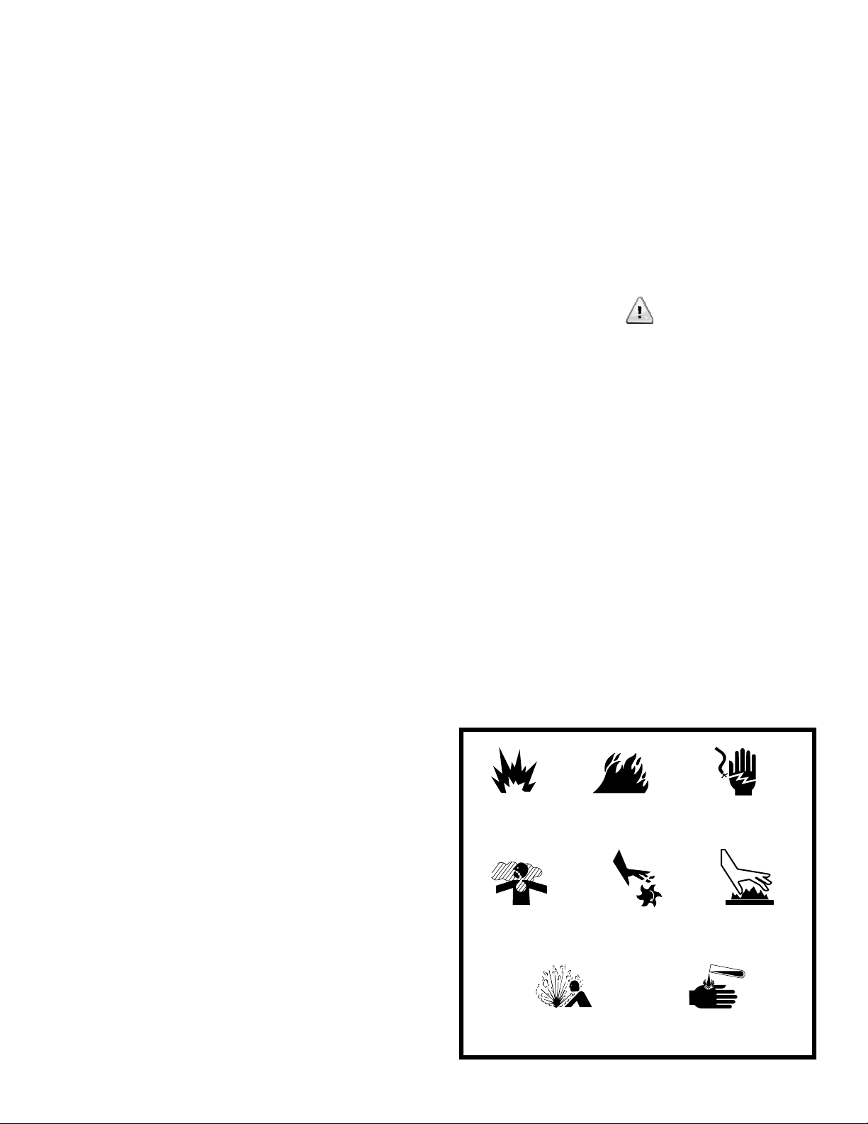
A LIST OF HAZARD SYMBOLS
AND THEIR MEANINGS
Explosion
Toxic Fumes
Fire
Rotating Parts Hot Surface
Electrical Shock
Chemical Burn Explosive Pressure
PAGE 3
WARNING
The engine exhaust from this product contains
chemicals known to the state of California to cause
cancer, birth defects, or other reproductive harm.
NOTICE
● For all safety reasons to the equipment, GILLETTE
recommends installation, start-up and service be
performed by experienced personnel.
● Sufficient, un-obstructed flow of cooling air is
critical for correct generator operation.
● The generator must be installed outdoors, away
from an over-hang roof where ice and snow could
avalanche onto generator and away from sprinklers
that could throw water up into cooling vents of
generator.
● Electric load applied to generator should be no
more that 75% of generator maximum rating to avoid
constant maximum generator load use.
● Generator should not be exposed to excessive and
constant moisture, dust, dirt, or corrosive
environments.
● If connected loads cause over heating or excessive
vibration, an overload condition exists. Remove
loads until condition stabilizes.
● Do not sit, step, or load heavy items on generator
roof. Added stress can cause breakage.
● Do not start generator with air cleaner, air cleaner
cover, or oil dipstick removed, nor with oil drain hose
in open drain position.
● Keep a fire extinguisher rated “ABC” close by your
generator and be familiar on how to use it. Consult
your local fire department, for additional fire
prevention ideas.
● Be sure that a positive manual fuel valve be
installed in fuel line feeding generator.
● Do not tamper with engine controls, generator is
factory adjusted to supply rated voltage and speed.
● Never operate generator when ambient
temperature is over 105º F, as electrical insulation
system may fail.
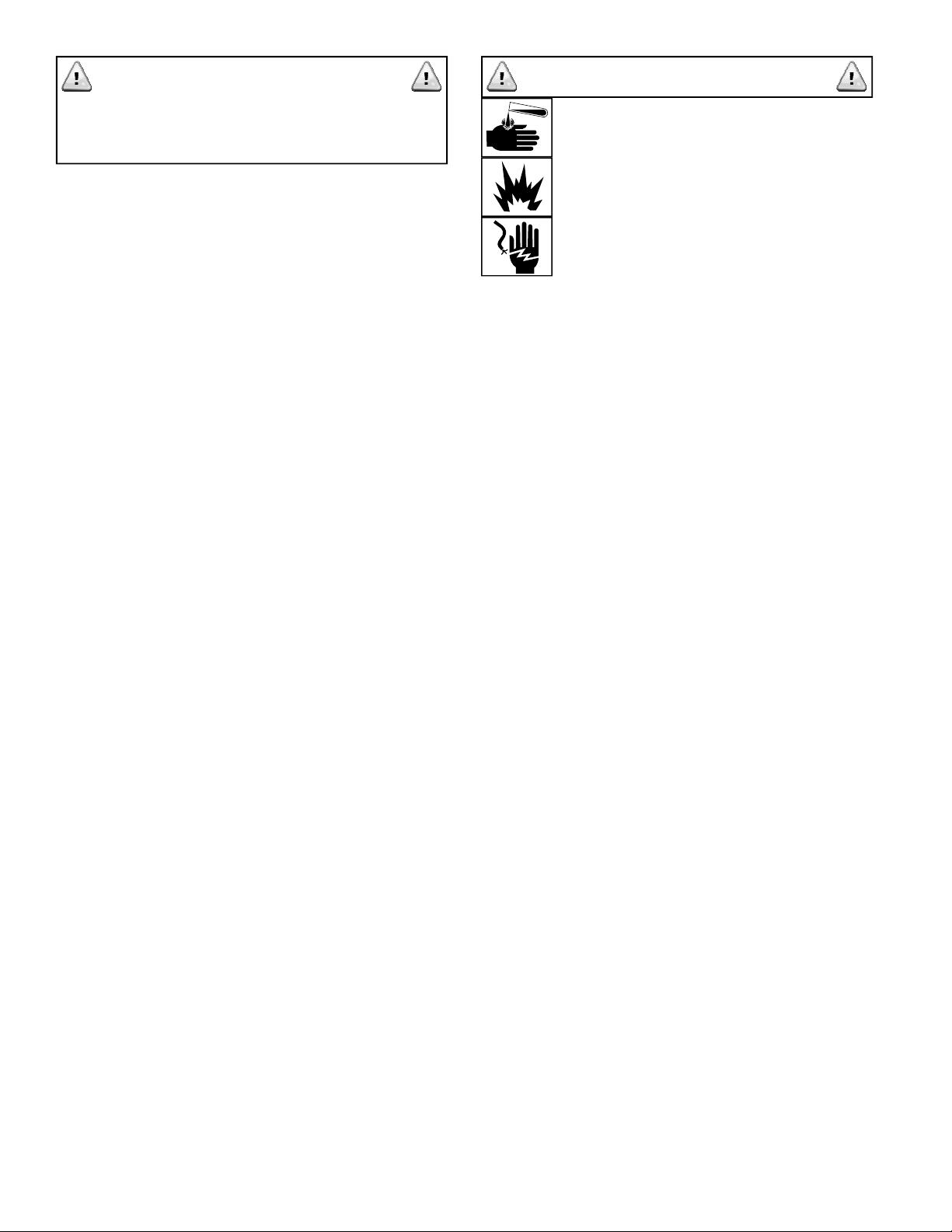
WARNING
STARTING BATTERY
PRECAUTIONS
Starting batteries are not furnished with
your generator set, but they are available
through your installing contractor. The
home standby generator requires a Group
36, 12 VDC fully charged battery with
minimum 390 cold cranking amps.
● Released battery electrolyte can burn your skin
and eyes and is toxic.
● When electrolyte touches skin, wash it off
immediately with water and seek medical attention.
When electrolyte contacts eyes, flush thoroughly with
water and seek medical attention.
● Spilled electrolyte must be washed away with an
acid neutral agent. Use a solution of one pound
bicarbonate of soda to one gallon of water, and wash
down acid effected areas until evidence of acid
foaming reaction has ended.
● A battery provides risk of electric shock. Remove
watches, rings, or other metal items when working
with batteries. Use tools with insulated handles.
● When disconnecting battery cables, always
disconnect the battery charger first, the positive
battery cable second, and negative battery cable last.
When reconnecting cables, always reconnect the
positive battery cable first, then negative cable, and
reconnect battery charger last, to reduce possible
arching.
● Discharge body static electricity by touching a
grounded metal surface on generator before touching
battery.
● Do not dispose of batteries in a fire and do not
open or mutilate a battery, as the battery is capable of
exploding.
● Lead acid batteries present a risk of fire or
explosion because they generate hydrogen gas,
within. Do not smoke, nor have flame or spark in a
battery area.
PAGE 4
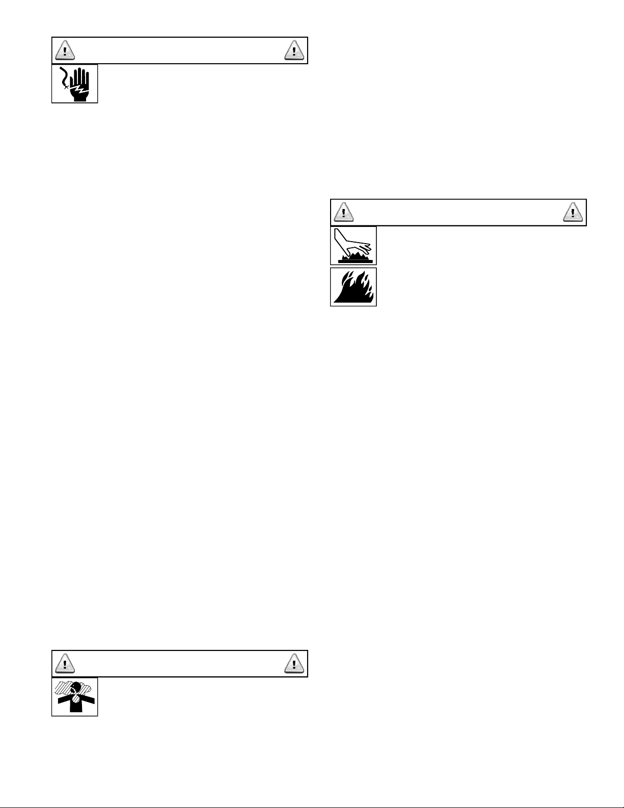
DANGER
ELECTRICAL HAZARDS
A generator produces dangerous electric
voltages and can cause a fatal electric
shock and will cause sudden illness, dizziness, and
incoherent actions.
● Despite the safe design of this GILLETTE
generator, operating it carelessly, neglecting its
normal maintenance, or being ill informed of proper
operations can cause possible serious injury or death.
● Avoid contact with bare wires, connection points,
etc., while generator is running.
● Do not touch any kind of electrical circuit while
standing in water, while barefooted, or while hands or
feet are wet or moist.
● Never wear any type of jewelry while working on a
generator. Jewelry will conduct electricity, causing
electric shock.
● If generator must be serviced while it is running,
stand on a dry, insulated surface from ground to
reduce shock hazard. Never service a generator in
the rain or snow.
● Do not allow unqualified or ill-experienced
persons to operate or service generator.
● Remain alert at all times. Never work on a
generator when you are physically or mentally
fatigued.
● This generator is equipped with a ground terminal.
Always complete the grounding path from generator
to an external grounding source to prevent possible
electric shock.
● In case of electric shock, shut the generator down
at once. If this cannot be done, free the victim from
source of live electric power. AVOID ANY DIRECT
CONTACT WITH VICTIM OR THE LIVE
ELECTRIC POWER. Use a dry piece of wood, a dry
rope, or any other such non-conductive item, to free
the victim from source of power. If victim is semi or
totally unconscious, apply CPR (cardio-pulmonary
resuscitation) and call for medical help immediately.
DANGER
Breathing carbon monoxide will cause fatigue,
headache, dizziness, vomiting, fainting, and in
prolong conditions, even death.
● Operate generator only outdoors, where adequate
ventilation is available. Avoid generator installations
under decks, inside garages or carports, in
basement, along side home exterior within five feet of
home vent, roof overhang vent, a window that can be
opened, or other such home invasion points. Use
same precautions when installing generator at
property line, close to a neighbor’s home, or any
buildings that house animals.
WARNING
POTENTIAL BURN OR FIRE
CONDITIONS
Contact with exhaust muffler and exhaust
pipe can result in serious burns.
Exhaust heat may ignite combustibles such as leaves
or other such debris that is allowed to accumulate
around base of generator where exhaust exits.
● Do not touch hot exhaust or engine parts, and
avoid hot exhaust gases.
● Keep at least a three foot clearance on all sides of
generator.
● Do not install generator any closer than five feet
from any combustibles or buildings with walls having
less than one hour, fire rating.
● Code of Federal Regulation (CFR), Title 36, states
that generators must have a spark arrestor attached to
muffler outlet pipe, to eliminate sparks from engine
operation. USDA Forest Service standard #5100-C
requires spark arrestor protection when generator is
operated within federal parks and forests.
● Generator installation must always comply with
local codes, standards, laws, and regulations. Check
with your local fire department to learn of these
precautions. Keep a fire extinguisher (rated “ABC”
by NFPA as appropriate use on generator fires)
nearby, at all times. Keep the extinguisher properly
charged and become familiar with its use.
CARBON MONOXIDE POISON
A running engine produces a poisonous gas from its
muffler exhaust pipe. This is an odorless, invisible,
and colorless poison that cannot easily be detected.
PAGE 5
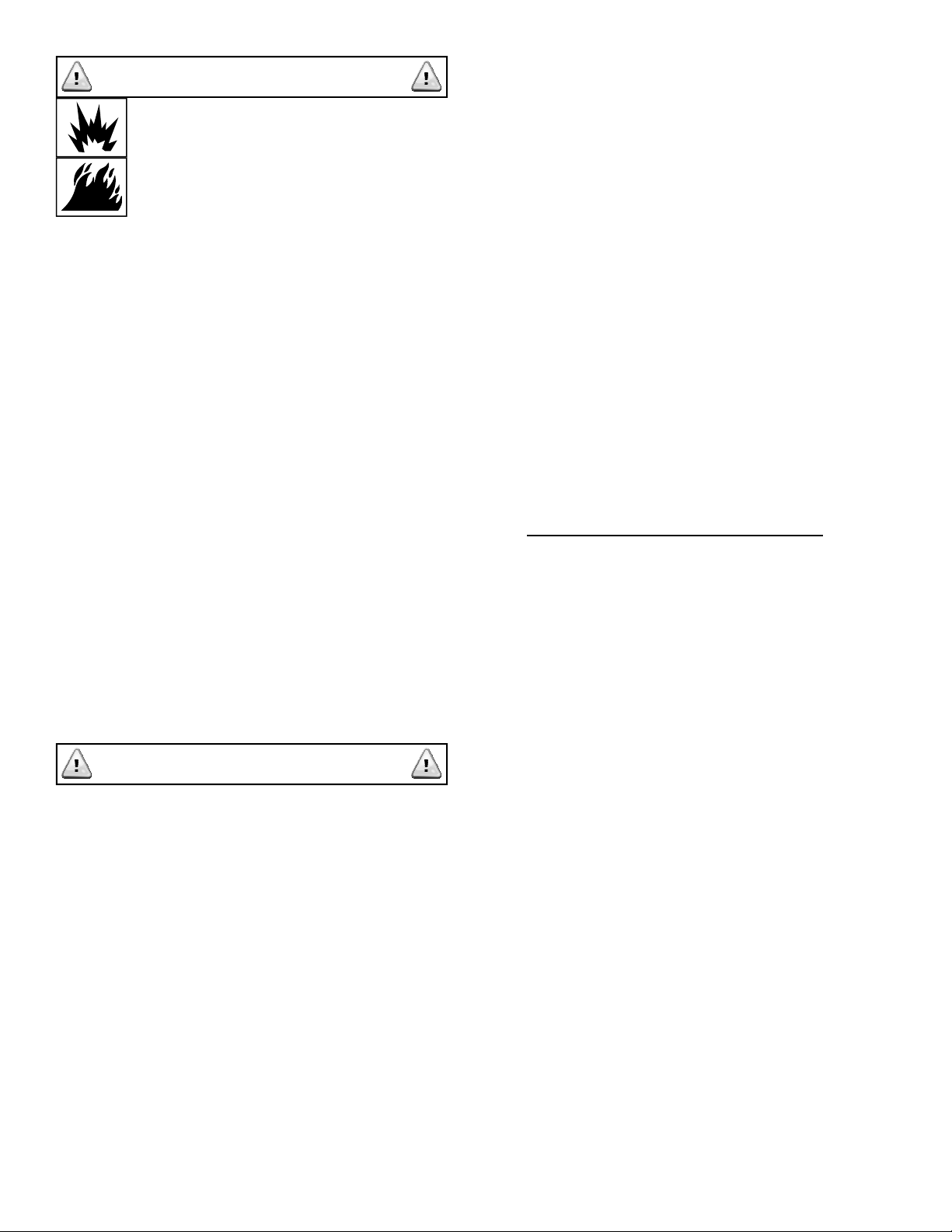
WARNING
FIRE OR EXPLOSION CONDITIONS
Gaseous fuels such as natural gas (NG) and
liquid propane (LP) are extremely
explosive. Make sure the fuel supply
system is installed in compliance with local
and state fuel codes and regulations. Fuel leaks when
ignited, can cause fire and explosion, resulting in
harm or possible death.
● Before initial generator start-up, all fuel system
lines must be purged and leak tested according to
applicable codes by experienced service personnel.
No leaks are permitted.
● Do not smoke or allow open flame near generator
while servicing fuel system or battery. Lead acid
battery will emit a highly explosive hydrogen gas that
can be ignited. Leaks in LP or NG system can be
ignited. Both are conditions that can cause fire and/or
explosion, leading to possible death.
● Do not operate generator if smell of fuel is
detected.
● Wipe up any oil spills immediately. Remove any
debris that has accumulated inside or around
generator base and housing.
● Always maintain a scheduled inspection of entire
fuel system and starting battery, looking for leaks or
other negative conditions.
CAUTION
Following is a list of potential events that might result
in minor or moderate injury or damage to the
generator.
● Never operate generator with oil dipstick partially
seated or completely missing.
● Never operate generator without air cleaner and
cover in place.
● Always check oil drain hose or radiator drain hose
for leaks.
● Generator operating speeds beyond 3750 RPM
increase risk of operator injury and engine damage.
● Never insert any objects through generator
cooling slots.
● The control panel and wiring access area doors
must be installed at time of operation.
● If connected electrical items overheat, disconnect
them immediately.
● Immediately shut down generator if it looses
electrical output, shows sparks, smokes, emits flames,
vibrates, or shows any other abnormal operation.
● Do not modify generator design.
● Do not modify carburetion system, as it is factory
set for C.A.R.B./EPA emissions certification.
This concludes the limited hazard listing. However,
GILLETTE cannot possibly anticipate every possible
hazard. Therefore, the warnings in this manual, plus
the warning tags and decals attached to the generator
are not all inclusive. If the generator operator has a
different operating method, other than described in
this manual, than operator becomes responsible to
make sure that different procedure, work method, or
operating method is totally safe, against harm and
hazards to operators, buildings or environments.
UNPACKING AND INSPECTION
After receiving the generator, note that it is mounted
on a heavy wood skid base and protected by a
multiply cardboard container. While the
transportation carrier is still present, note the
condition of skid and cardboard box. If noticeable
damage is apparent, immediately remove cardboard
box and inspect generator for possible freight
damage. If damage occurs, make a note of damage
on carrier’s freight bill and have truck driver sign his
name on the freight bill, under “Consignor’s memo of
loss or damage”.
If shipping container shows damage of any kind, and
time does not permit container removal for actual
generator inspection, while transportation carrier is
still available, be sure to:
• Make note of container damage “with possible
interior product damage” on carrier’s freight bill.
• Have truck driver sign his name on freight bill
under “Consignor's Memo of Loss or Damage”.
This action will help prove your case against shipper.
Always save shipping materials in the event that genset must be sent back to factory due to need of
extensive repairs.
If damage is noticed after carrier leaves, contact the
carrier for “concealed damage” form. NOTE:
Missing or damaged parts on generator, is not a
warranty claim.
PAGE 6
GENERATOR CONTENTS
The GILLETTE home generator set is supplied with
the following components:
● Home generator system within soundproofed all
weather metal enclosure (Depending on option
choice, this can be an open set or a super-silent
enclosure add).
● Residential muffler system for quiet operation.
● Choice of (3) gen-set mounting systems:
A) Base direct mounting to concrete slab.
B) Base direct mounting to crushed gravel base,
secured in ground with ground stakes.
C) Base with plastic pad for floating mount on
crushed gravel.
● 3/4” NPT female coupling for gas connection.
● Four lifting holes with cover plugs.
● Two locking door keys (NOTE: One key fits all
locks.)
● One spare 20 amp fuse. (Located just above fuse
holder in control panel wiring area)
● Diagnostic LED panel.
● One owner/operator panel.
NOTE: All accessory items will be pre-mounted and
wired to generator. If separate automatic transfer
switch (ATS) is ordered, it is placed on top of
generator shipping box and steel banded in place.
AUTOMATIC TRANSFER SWITCH (ATS)
DANGER
If this generator set is used to provide
temporary electric power to circuits when
loss of normal utility power occurs, it is required by
National Electric Code, to install an automatic transfer
switch (ATS).
The ATS must isolate the home electrical system from
the utility electrical distribution system when the
home generator is operating (see NEC 700, 701, and
702). Failure to isolate an electrical system with an
approved ATS will result in damage to home
generator and also can result in severe injury or
death to utility power workers who may receive
electrical back-feed shock from the home
generator set.
The automatic transfer switch is an optional selection
and can be used with any model GILLETTE home
generator set. All installation procedures, operating
cautions, and warranties are responsibility of the
separate manufacturers of the ATS.
PRE-INSTALLATION PLANNING
The beginning installation requires some thought and
planning. The following illustrations are meant to
familiarize reader with typical installation
circumstances and to plan the best installation
possible.
First, Federal, State, and local codes may be a factor.
The local fire department can be of help on learning
these codes. As with all generators, your generator
must be installed in accordance with current NFPA-37
and NFPA-70 standards. Contact your local electrical
inspector or city hall to insure you are aware of all
codes and regulations. Contact your natural gas
supplier to verify that increased BTU gas demand can
be handled with existing NG gas meter. The same is
true for LPG fueled generators.
The most common fuel mistakes are:
A) Not a dedicated fuel line from fuel source to
generator, on either LPG or Natural Gas fuel.
B) Not having a dedicated primary fuel regulator for
only the generator, while using LPG tank.
C) Wrong fuel pressures. (See fuel pressure
information on page 14)
D) Not understanding that fuel pipe diameter must
increase in direct proportion to fuel line length. (See
gas charts on page 12 for further details)
E) Wrong primary regulator. This is a common
problem, using an existing regulator on a LPG Tank is
typically too small for the supply needed for a
generator.
Locate the generator site. It should be as close as
possible to the natural gas meter, and as close as
possible to the home electrical distribution panel.
Determine the type of generator anchoring. There
are three types:
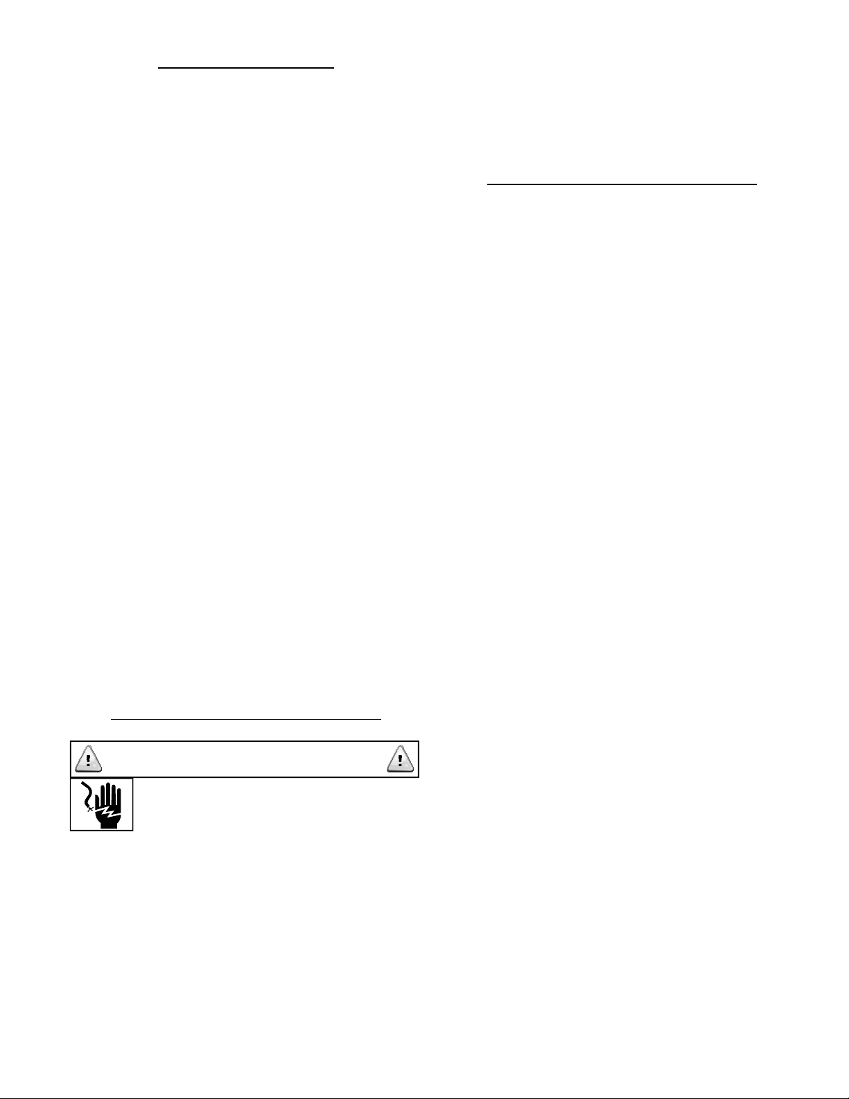
1) ACCEPTABLE: Generator is mounted on a
composite (plastic) pad, placed on a bed of pea
gravel or crushed stone. It “floats” in place. (See
Illustration #1)
2) ACCEPTABLE: Generator is mounted directly on a
bed of pea gravel or crushed stone (no composite
PAGE 7
3) PREFERRED: Generator is mounted directly on a
concrete slab, 4 inches thick, extending 6 inches
beyond generator perimeter, and bolted in place.
This method is for those locals with “high wind”
considerations. (See Illustration #3)
If gravel bed is chosen, its perimeter must be eight
inches larger than generator base. Dig a rectangular
area six inches deep, cover with landscape cloth (so
drainage can take place) and fill with pea gravel or
crushed stone. Final gravel level must be two to three
inches higher than original level to ensure water runoff away from generator. A normal plastic landscape
border can be used between grass and gravel area to
provide a more attractive installation.
Compact and level the stone. Place generator on
stone using either the “composite” pad (optional
equipment) or place aluminum generator base
directly on gravel, using ground stakes for a fixed
installation.
GROUND
GENERATOR BASE
GRAVEL BED
GRASS
ILLUSTRATION #2: Generator is placed on top of
gravel bed. The ground stakes are driven through
the slots in generator base, to hold it in place on
gravel bed. CAUTION: Make sure there is no
underground electric wires, gas lines, sprinkler
lines, or any other vulnerable items, directly in
the path of these two ground stakes.
BOLTED TO
CEMENT PAD
BOLTED TO
PAD
GENERATOR BASE
COMPOSITE PAD
GRAVEL BED
GRASS
ILLUSTRATION #1: Composite pad bolted to
generator base and placed over a bed of crushed
stone or gravel.
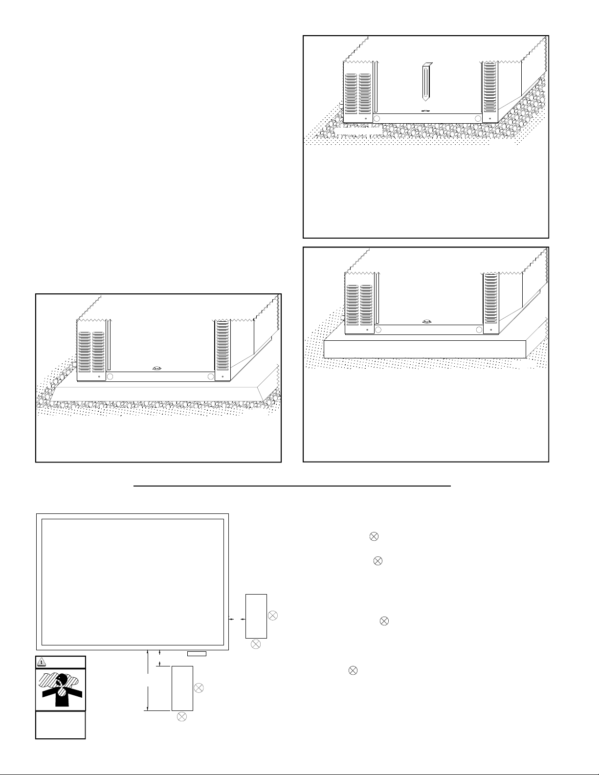
SUGGESTIONS FOR GENERATOR LOCATIONS
OCCUPIED
BUILDING
#2
5'
GENERATOR
(B)
DANGER
TOXIC FUMES
MAY ENTER
BUILDING
APPROX.
10'
5'
PREFERRE D
GAS
METER
(A)
#1
GENERATOR
(B)
ACCEPTAB LE
(A) = SPS M ODELS
(B) = SPP MO DELS
GENERATOR BASE
CEMENT PAD
ILLUSTRATION #3: Generator base is bolted
directly to a poured concrete slab (provided by
others). Notice that all three illustrations provide
bolting or staking methods that are always secured
from inside the generator housing, behind locked
doors. This is designed to deter theft of your home
standby generator set.
1) Always install your generator within 20 feet from natural
gas meter. Further distances may cause “starving” of fuel
from generator engine.
2) Exhaust end must always be turned away or parallel
with building and minimum 5 feet away.
3) Exhaust end is not to be directed towards play
areas, patios, under canopies or overhangs, or where
people or animals congregate.
4) Do not install generator under deck of house.
5) Furnace and other air intakes should be minimum 10 feet
(A)
from exhaust end
6) Windows and doors on adjacent walls, to be closed at all
times, during generator operation.
7) Nearest roof overhang vent should be 10 feet from
exhaust end
8) If electrical distribution center panel is far away from
gas meter, locate generator close to gas meter. Installation
costs are lower, if electric wiring is oversized for long
distances, to utility point rather than oversized fuel lines to
gas meter.
GRASS
PAGE 8
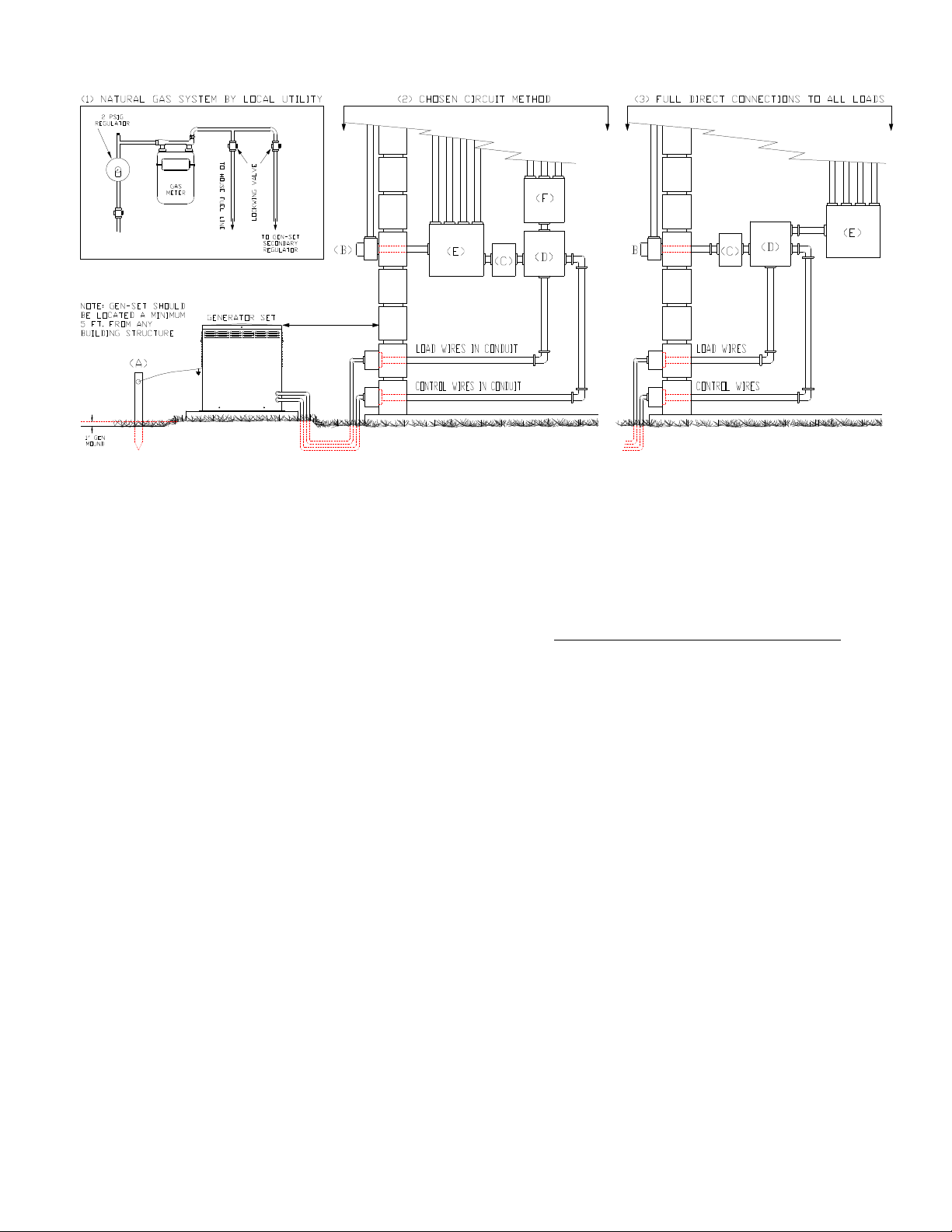
TYPICAL EMERGENCY GENERATOR INSTALLATION PRACTICES
MIN IMUM 5 FT
(1) Drawing shows a typical gas utility approach on how to
bring natural gas fuel to the gen-set. The fuel from utility is
connected by dedicated fuel line, to the installed 4 ounce, 7”
water column secondary regulator, inside gen-set housing.
CAUTION: Consult your natural gas supplier about your meter
size. Most meters must be replaced with a larger BTU size, due
to larger demand of BTU’s from generator. The same
procedure is also used with LPG: a 6 ounce, 11” water column,
dedicated primary regulator is placed at fuel outlet of “vapor
withdrawal” LPG tank. Fuel is piped directly to LPG 6 ounce,
11” water column secondary regulator, inside gen-set housing.
(2) Drawing shows chosen circuit connection: Load circuits are
selected based on importance of needs, plus the starting and
running amps. All connected loads should not exceed the amp
size of generator. The auto transfer switch should equal or
exceed total amp load of (F), smaller distribution panel.
When “Chosen” load is matched to gen-set amp size, the genset is never overloaded.
(3) Drawing shows full load connection: The gen-set output is
applied to the entire load of the utility electrical distribution
panel. For this installation, the auto transfer switch, must be of
same amp size as utility power. This is the easiest, lower
priced electrical installation, but subject to gen-set shutdown
whenever load amps exceed gen-set amp capacity.
(A) Drive a corrosion resistant steel stake, into ground and
attach a 10 gauge stranded copper wire from stake to ground
lug on outside of gen-set. This bleeds off any potential
lightning strike and any static electricity, which can occur on
metal parts of ungrounded generators. For a non-separately
derived system (where normal electric utility power is in
building and gen-set is a back-up emergency power
supply), the gen-set neutral must connect only to utility
power neutral and not to the ground stake. The best place
for these two neutrals to meet (generator and utility neutral), is
in the automatic transfer switch. However, still connect gen-set
mechanical ground to the stake. All factory gen-sets, have a
“floating neutral” ready to be connected to utility neutral, by
installer.
(B) Normal utility power meter and power inlet to panel.
(C) Safety disconnect switch, sized to ATS amp rating.
(D) Auto transfer switch with UL-1008 label and NEMA-1
housing for inside installation. Consult factory for NEMA-3R,
outside installations.
(E) Original electric utility distribution panel.
(F) Separate, smaller distribution panel, with chosen circuit
loads.
HELPFUL INSTALLATION TIPS
● Mound the gen-set location upwards at least 1 inch from
normal terrain, for proper drainage. Fill an area 6 inches
larger than gen-set mounting pad perimeter and 3 inches
deep, with crushed gravel. This provides flexible settling of
gen-set and mounting pad. NOTE: Specific locales may
require a cement pad installation.
● Gen-set must be located minimum 5 feet from all structures.
This clearance will provide for ample service room.
● Watch out for roof overhangs. Snow, ice, or rain should not
be allowed to accumulate on roof, and cascade onto gen-set
roof.
● Check prevailing wind direction. Winds should blow
toward the engine end of housing, which is the normal cool air
intake end. The opposite end is hot air discharge.
● Engine exhaust from generator end is hot and dangerous.
Exhaust must be allowed to dissipate into free air zone, with no
obstructions (air conditioner condenser, buildings, plants,
trees, living quarters, etc.) within 5 feet.
● Control wires and load wires should be made in (2)
different circuit runs to auto transfer switch, to avoid any
possible magnetic interference between the two. These lines
should be underground for best protection.
● Don’t allow snow, ice, or debris to accumulate around and
on gen-set. If possible, plant a short hedge or a series of
evergreens, as a protective “wall”, 5 feet from gen-set on
windward (engine) side, to stop such accumulation, and still
PAGE 9

KNOW YOUR GILLETTE HOME GENERATOR
Compare the following illustrations and individual component locations, with your actual GILLETTE home
generator system. This will help familiarize yourself with the entire generator set.
Control, Wiring,
& Generator End
2)
1)
Cool Air Input
LEFT SIDE FACING ENGINE END WITH SERVICE PANEL REMOVED
1) Ground Wire to Ground Stake (Electrician)
2) Two Electrical Knockouts (Electrician)
3) Oil fill.
4) Engine.
5) Spark plug (Replace every 300 hours of use).
3)
4)
5)
6)
7)
Engine End
8)
Cool Air Input
9)
6) Oil cooler.
7) Oil filter (Replace every 200 hours).
8) Oil drain with flexible drain hose. NOTE: Change
oil after every 50 hours of use.
9) Dry fuel gas input (Always use flexible fuel line).
12)
13)
14)
11)
Engine End
10)
Cool Air Input
RIGHT SIDE FACING ENGINE END WITH SERVICE PANEL REMOVED
10) 12 VDC battery charger. Installer must connect
120 volt, 1 phase utility power to this charger.
11) 12 VDC engine starter motor.
12) Spark plug (replace every 300 hours of use).
13) Air cleaner element (Clean every 50 hours,
replace at 300 hours).
15)
16)
Hot
Muffler
Area
17)
Generator End
Cool Air Input
18)
15) Oil dipstick.
16) Muffler. CAUTION: Hot to the touch when in use.
17) Generator.
18) Battery tray (see page 16 for installation and
caution use).
PAGE 10
 Loading...