

Page 1
LEADER IN GENERATORS
BRUSHLESS
OWNER’S MANUAL
FOR GILLETTE PORTABLE GEN-SET MODELS: PP, GPN, GPNDL, GPGF, AND
PP-HGS WITH KW SIZES: 3.0, 4.0, 5.0, 6.5, 7.5, 9.0, 10.5, 12.0, AND 15.0 KW
PORTABLE GENERATORS
READ ENTIRE INSTRUCTION MANUAL FOR SAFE OPERATION OF
GENERATOR. ALSO READ SEPARATE AND INCLUDED ENGINE
MANUAL BEFORE ACTUAL USE. IT IS IMPORTANT FOR USER TO
KNOW HOW TO SAFELY START AND HOW TO SAFELY STOP
ENGINE,BEFORE ATTEMPT OF FIRST TIME USE.
GILLETTE GENERATORS, INC.
1340 W ADE DRIVE
ELKHART, INDIANA (574) 264-9639
EFFECTIVE DATE: APRIL 2007
FAX NUMBER (574) 262-1840
! !
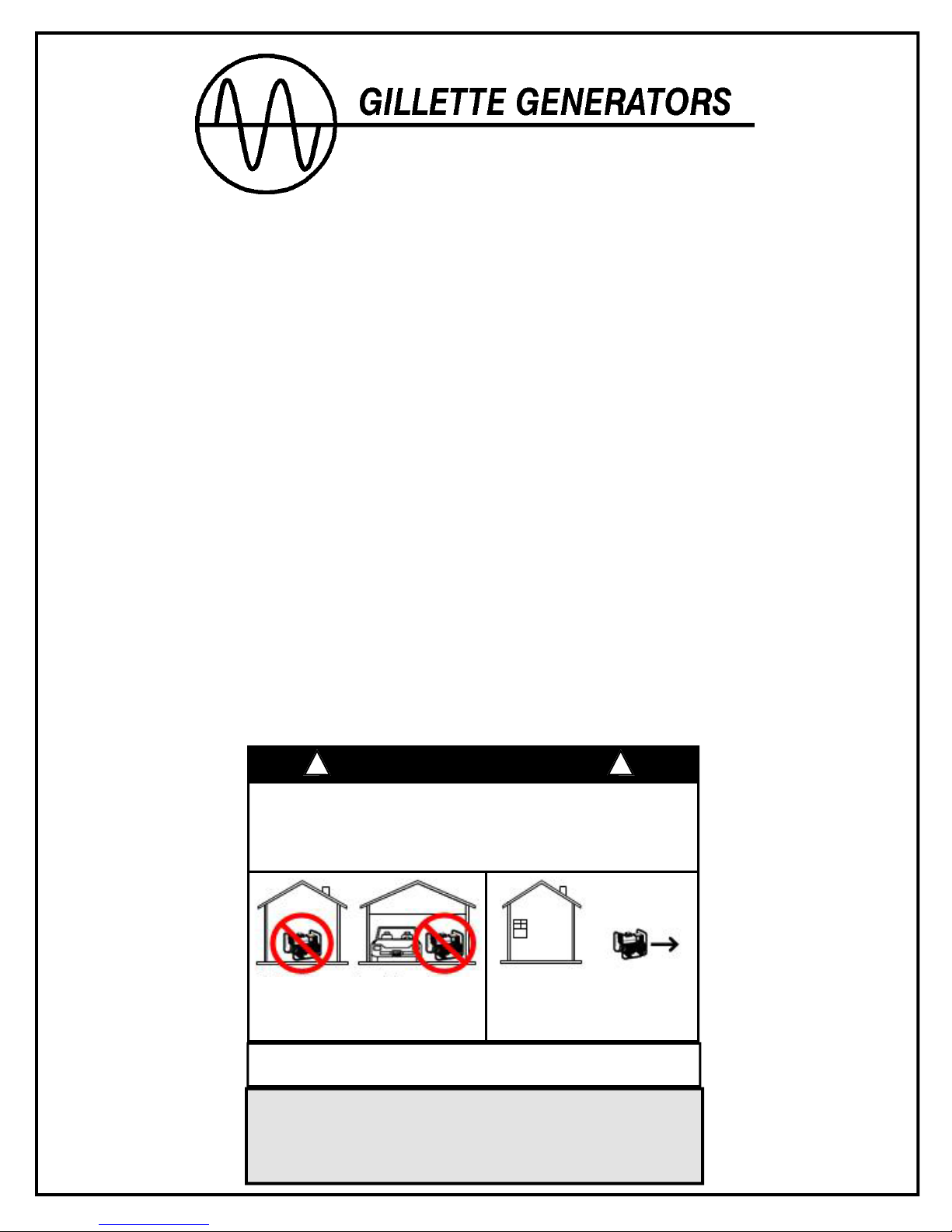
Using a generator indoors CAN KILL YOU IN MINUTES.
Generator exhaust contains carbon monoxide. This is a
poison you cannot see or smell.
NEVER use inside a home
or garage, EVEN IF doors
and windows are open.
Avoid other generator hazards.
READ MANUAL BEFORE USE
*CALIFORNIA PROPOSITION 65 WARNING *
ENGINE EXHAUST FROM THIS PRODUCT CONTAINS
CHEMICALS KNOWN TO CAUSE CANCER, BIRTH DEFECTS
OR OTHER REPRODUCTIVE HARM.
DANGER
Only use OUTSIDE and
far away from windows,
doors, and vents.
Page 2
PREFACE:
This compact, lightweight GILLETTE generating set is a very
high quality, portable electric power source. It is intended for
temporary electric power to power tools, lighting, small
electric motors and other similar industrial, commercial and
construction machinery.
Before starting your generating set, thoroughly study the
instructions and cautions in this manual to insure you are fully
acquainted with the operation of this set. Proper preparation,
operation and maintenance will result in operator safety, best
performance and long life of generating set.
For detailed engine handling, always refer to the separate
engine instruction book furnished with the set.
GILLETTE is constantly improving its products. The
specifications outlined herein are subject to change without
prior notice or obligation. The purchaser and/or user
assumes liability of any modification and/or alterations made
on this equipment from original design and manufacture.
Before using, user shall determine the suitability of this
product for its intended use and assumes liability therein.
1. INTRODUCTION:
This generating set consists of generator, engine, base and
power take off means.
The generator is a two pole, 3600 RPM (3000 RPM for 50
hertz operation), brushless, revolving field, synchronous type
with one ball bearing. The rotor of the generator is directly
connected to the engine crankshaft and the stator is rigidly
coupled to the engine casting, through the bearing casting.
Other styles include a generator only, key shaft extended,
two bearing, foot mounted, for use with couplings or V-belt
and pulley method of connection to a key shaft engine.
2. FEATURES:
POWER ASSIST is an exclusive excitation system using
power capacitor and unique new winding design to insure
minimum power fluctuations, maintains excellent voltage
regulation without other external devices, and provides
superior induction motor load starting power.
INNOVATIVE WINDING consists of all copper field and rotor
windings, large diameter electrical grade steel laminations,
Class H high 200° C heat insulation protection, all to insure
against burn-outs or early failures.
3. RULES FOR SAFE OPERATIONS:
Safety precautions are essential when operating this
equipment. Using this equipment with respect and caution
will considerably lessen the possibilities of personal injury.
This manual will warn of specific personal injury potential,
and these warnings will be designated by the symbol:
Read your generator and engine operator manuals carefully,
know your equipment before you use it. Consider the
application, limitations and potential hazards before
operation.
!
This generating set is equipped with a ground terminal
for your protection. Always complete the grounding path from
the set to an external grounding source to prevent electrical
shock.
Electric load applied to generating set must be within its
rating. Overloading will damage set or shorten its life.
Engine must not be run at excessive over-speed conditions.
Do not tamper with parts that may increase speed and result
in damage to set.
Generating set must reach operating speed before load is
applied. Disconnect electric loads before shutting engine
down.
!
!
Maintain electrical cords in good condition. Worn,
bare, frayed or otherwise damaged cords can cause
electric shock.
!
Never operate the generating set, or handle any
electrical equipment while standing in water, while
barefoot, while hands are wet, or while in the rain or snow
to prevent dangerous electric shock.
!
A ground fault circuit interrupter (GFCI) should be
used in damp or high electrical conductive areas and
construction job-sites to prevent electric shock.
!
Before working on the engine or the generator,
always remove the spark plug or the spark plug wire to
prevent accidental starting.
!
Check generating fuel system on a regular basis.
Look for signs of leaks, deterioration, chafed or spongy
fuel hose, loose or missing fuel hose clamps, rusted or
damaged fuel tanks, defective fuel shut-off valve. Correct
any defects before operation.
!
Always provide adequate ventilation. Do not
operate set in any enclosed or narrow space. Engines
consume oxygen and give off deadly carbon monoxide
poisonous gas. Improper ventilation will cause damage to
set and possible injury to people.
!
Avoid severe burns by not touching hot muffler, hot
exhaust manifold, or engine cooling cylinders.
!
Keep generator and engine clean. Remove all oil
or gasoline deposits, and accumulated dirt from set and
immediate area. Poor housekeeping creates a fire hazard.
!
Keep a fire extinguisher close by your set and be
familiar on how to use it. Consult your local fire
department for correct extinguisher type.
!
The unit should never be operated under the
following conditions:
conditions:
A. Good ventilation. Avoid areas where vapors
can be trapped such as boat bilges, basements, garages,
etc. Air flow and temperatures are important. Never
operate set when temperature is over 110° F.
B. Engine exhaust gas is poisonous and
dangerous. The gas contains carbon monoxide, an
odorless, invisible gas which causes serious illness or
death if breathed. Always direct exhaust fumes away from
humans.
C. Avoid refueling while engine is hot, still running,
in the dark, near open flames or sparking electrical
devices.
Change in engine speed, slow or fast
A.
Overheating in load connecting devices.
B.
Sparking or arcs from set.
C.
Loss of electrical output.
D.
Damaged receptacles.
E.
Engine misfire.
F.
Excessive vibration.
G.
Enclosed compartments, or confined areas.
H.
Flame or smoke
I.
Rain, snow or water conditions.
J.
Operator non-attendance.
K.
!
The unit must be operated under the following
Page 1
Page 3
4. INSTALLATION:
OUTDOORS: Choose a location where generating set will
not be exposed to rain, snow or direct sunlight. Make sure
that set is on secure level ground so that it cannot slide or
shift around. Also, position the set so that the exhaust will
not be directed toward nearby people.
The installation site must be free from water, moisture, or
dust. All electrical components should be protected from
excessive moisture or deterioration of insulation system will
happen and result in grounding or short circuit of
generating system.
Foreign matters, such as dust, dirt, sand, lint, or abrasive
materials can cause damage to generator and engine if
allowed into its cooling system.
INDOORS:It may be necessary to install generating set
inside a type of shelter. If this is your choice, several
factors must be considered. Whenever an engine is
installed indoors, the exhaust fumes must be vented to the
outside. The engine should be installed at least two feet
from any outside wall. If you use an exhaust pipe that is
too small in diameter or use more than two right angles, an
excessive back pressure will result, which can overheat the
engine, lose horsepower, and destroy valves. Always use
an approved flexible exhaust hose between engine and
rigid pipe. Consult a local engine specialist or your local
fire department for special instructions on these types of
installation. Never install generator indoors where humans
habitat.
!
Do not try to install your generator inside
confined areas, without the help of experienced engine and
generator technicians. Improper inside installations can
cause health hazards or death.
!
Remember, exhaust fumes are deadly carbon
monoxide gas, and it must be vented to the outside where
there are no people. Cooling air of sufficient amounts must
be brought in and exhausted out to insure proper cooling of
engine and generator.
5. PRE-START PREPARATIONS:
Your generating set has been thoroughly inspected prior to
shipment from the factory. However, be sure to check for
damaged parts, loose nuts and bolts, which could have
occurred in transit.
GROUND. The ground terminal on the generating set
should always be used to connect the set to a suitable
ground. The ground path should be #8 size wire and not
over six foot long. Insert one end of #8 wire into ground
terminal and tighten set screw onto wire securely. Connect
other end of wire to a suitable ground.
LOCATE AND BE FAMILIAR WITH
THE FOLLOWING ITEMS:
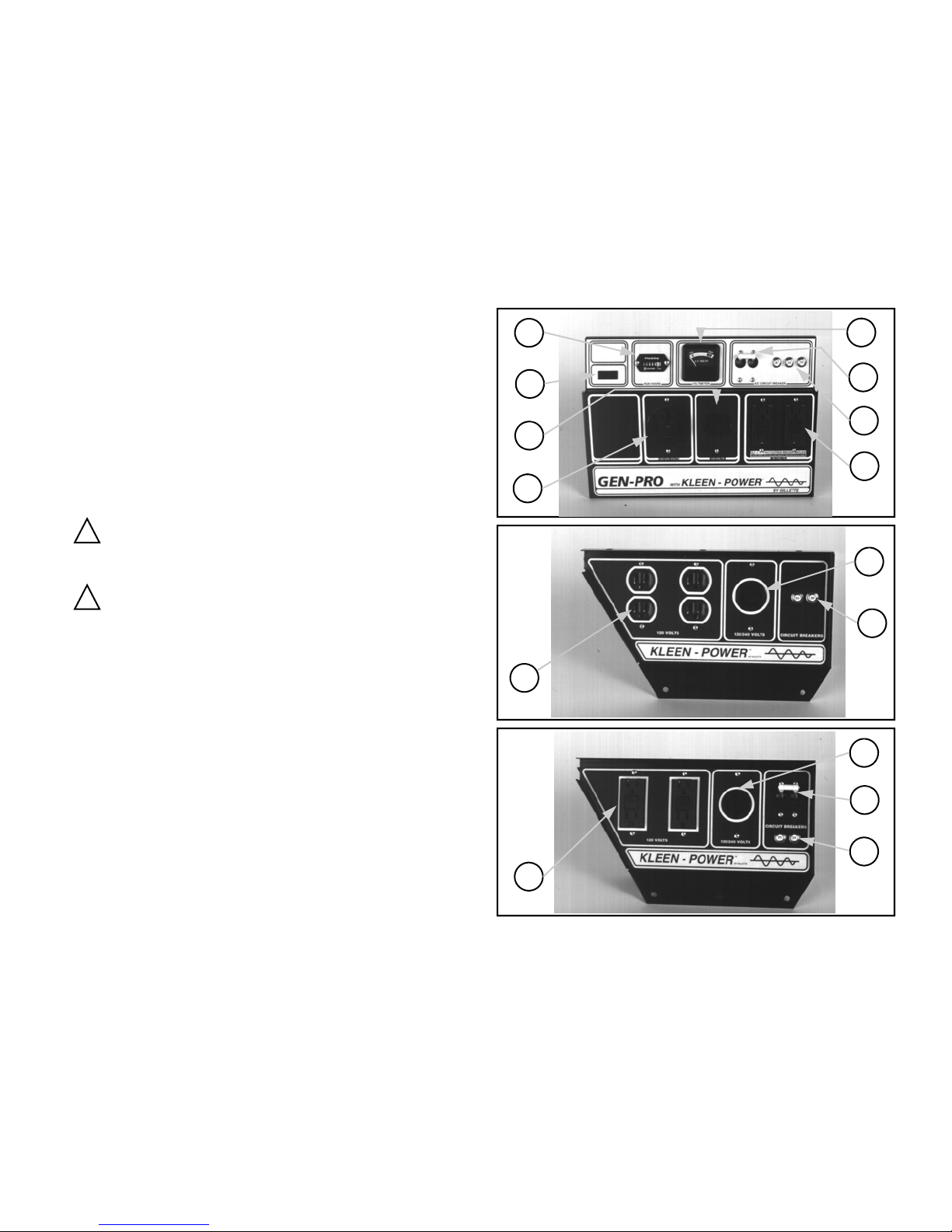
RECEPTACLES. (1, 2, 3, 9, & 10) Most generator sets will
have a receptacle panel with a variety of components,
depending on the specific generator set. It is important to
know that all receptacles conform to National Electrical
Manufacturer's Association (NEMA) regulations and
matching NEMA male caps should always be used.
Always use grounded male plugs. The neutral line of
generating set is mechanically grounded to frame.
CIRCUIT BREAKER. (4 & 5) All portable single phase
generating sets have circuit breakers to protect against
electrical overloads. If possible, it is advised to switch off
or remove electric load before starting engine.
BALANCED LOAD. Special winding design will
automatically not allow an unbalanced electric load
condition while using a large 120 volt load.
ENGINE STOP SWITCH. (6) Some models have the
engine stop switch on the receptacle panel and some
models have this stop switch located on the engine.
Always locate this switch and be familiar with its location
before operating the set.
HOUR METER. (7) Some models indicate the hours of
use to help in determining service periods.
VOLT METER. (8) Some models indicate the voltage
output of generator set.
GEN-PRO AND POWER-PRO
RECEPTACLE PANELS
7
6
9
10
1
2
1 STANDARD 120 VOLT, 15 AMP, NEMA 5-15R RECEPTACLE
2 SPECIAL 120 VOLT, 15 OR 20 AMP, NEMA 5-15R GFCI
RECEPTACLE WITH ELECTRIC SHOCK PROTECTION.
3 STANDARD 120/240 VOLT 20 OR 30 AMP NEMA L14-20R OR
NEMA L14-30R TWIST-LOCK, 4 WIRE RECEPTACLE.
4 PUSH BUTTON, THERMO RE-ACTING MAIN CIRCUIT BREAKER
5 TWO POLE MAGNETIC RE-ACTING MAIN CIRCUIT BREAKER
6 OPTIONAL ENGINE START-STOP SWITCH
7 RUN TIME METER
8 VOLTMETER
9 STANDARD 120 VOLT, 30 AMP, NEMA L5-30R RECEPTACLE
10 SPECIAL 120/240 VOLT 50 OR 60 AMP, NEMA 14-50R OR
NEMA 14-60R FULL POWER RECEPTACLE
8
5
4
2
3
4
3
5
4
Page 2
Page 4

FUEL VALVE. The generator fuel tank has an ON-OFF
valve mounted underneath tank. Always keep this valve
closed when the set is not in use.
FUEL CAP. Some models have fuel level indicator built
into the extended run fuel tanks. You can always safely
monitor fuel level on all tanks without cap removal.
OIL-GUARD. All models have protection against damage
to engine resulting from low oil level. As the oil level falls
below safe level, the engine automatically shuts down and
the engine will not restart, until oil is added.
6. LOAD APPLICATION:
Determine the total electric load before it is connected to
generating set to prevent overloading. Always compare
the generating set nameplate data with that of the
equipment to be used to insure that watts, volts,
amperage and frequency requirements are suitable for
operating equipment. Generally, the wattage listed on the
equipment nameplate is its rated output. However, some
equipment may require three to ten times more wattage
than its rating on the nameplate, as the wattage is
influenced by the equipment efficiency, power factor and
starting system. NOTE; If wattage is not given on
equipment nameplate, approximate wattage may be
determined by multiplying nameplate voltage by
nameplate amperage.
VOLTAGE X AMPERAGE = WATTS
When connecting a resistive load such as incandescent
lights, heaters or common electric power tools, a capacity
of up to the generating set full rated wattage output can be
used. When connecting a fluorescent or mercury light,
transformers, inductive coils, or electric motors a capacity
of up to the generating set full rated wattage output,
multiplied by 0.6 can be used.
CAUTION: Electric motors and electric motor driven
equipment will draw much greater amperage for
starting, than for running these motors. Follow the
chart for code G electric motors, but pay special
attention to caution concerning the code L electric
motors.
CAUTION: Code L Electric Motors, used on
equipment such as air compressors, air conditioners,
or submersible water pump motors require an
extreme high amount of starting power, up to 6 or 8
times the motor name plate running amps. The genset wattage rating must be sized to the electric motor
starting watts.
THREE PHASE. Some models are available with three
phase power upon special request. The nameplate
rating will always be shown as KVA (Kilo-Volt amps)
rather than the watts for single phase. If three phase
output (KVA) is not given on equipment nameplate,
approximate output can be determined by multiplying
volts X amps X sq. root of 3 X powerfactor, divided by
1000.
VOLTS X AMPS X SQ.-ROOT-OF-3 X P.F. / 1000=KVA
ELEC. MOTOR
HORSE POWER
1/2 2000 1100
1 3800 1800
2 6000 2800
3 8000 4000
4 11000 5500
5 13000 6500
CODE G ELECTRIC MOTORS
*STARTING WATTS
RUNNING WATTS
EXTENSION CORDS. When electric power is to be
provided to various loads at some distance from
generating set, extension cords are normally used.
These cords should be sized to allow for distance in
length and amperage so that the voltage drop between
the set and point of use is held to a minimum.
AMPS
LOAD
DROP CORD LENGTH IN FEET
AT IN #10 #12 #14 #16
240 V. WATTS
GA. CORD GA. CORD GA. CORD GA. CORD
10 2400 250 150 100 75
20 4800 125 75 50 25
30 7200 60 35 25 10
40 9600 30 15 10 *
50 12000 15 * * *
60 14400 * * * *
CAUTION: Equipment damage can result from low
voltage due to small wire size. * Not recommended.
GROUND FAULT CIRCUIT INTERRUPTION: When
certain adverse conditions exist, an electric shock
potential is possible to the operator of electric generator
sets. It is recommended by the NATIONAL
ELECTRICAL CODE (NEC) and OCCUPATIONAL
HEALTH AND SAFETY ADMINISTRATION (OSHA) to
utilize a device that will automatically disconnect the
electric load from the electric power source when these
health and the life threatening conditions exist.
This device protects you against hazardous electrical
shock that may be caused if your body becomes a path
through which electricity travels, to reach ground
potential. This could happen when you touch an
appliance or cord which is “Live” through faulty
mechanism, damp or worn insulation, etc. Also, be
cautious about touching plumbing or other mechanical
paths to ground.
Article 305-6 of the National Electrical Code, l990, states
that ground fault protection for personnel on construction
sites shall be provided for all l25 volt, l5 amp and 20 amp
receptacles. Gen-Pro portable generators provide this
personnel electric shock protection by means of a
"ground-fault circuit interrupter" (GFCI) built into its l5 and
20 amp, l20 volt receptacles. This UL approved device
meets OSHA and NEC requirements for electric shock
protection on job-site portable electric power appliances.
These GFCI protection devices should be tested for
correct operation before each use. Test procedure with
gen-set in operation: Push test button on GFCI
receptacles. The RESET button should pop out from
inner surface. This should result in no power at all from
receptacles protected by GFCI. Verify by plugging test
lamp or voltmeter into every GFCI protected receptacle.
If GFCI tests correctly (no power output), then push
RESET button back into place until it locks and remains
depressed for full power output.
CAUTION: RESET button will not remain in place if tests
do not meet correct standards or if RESET trips by itself
during normal use. DO NOT CONTINUE TO USE
GENERATOR SET. Consult a qualified repairman or
electrician to determine problem with GFCI.
WARNING: GFCI protection should not be considered
an all inclusive answer for total electrical shock
protection, as all possible use conditions are too
extensive to be considered.
WARNING: GFCI protection should not be used
directly or indirectly with life support apparatus or
associated circuitry.
Page 3
Page 5
DETERMINING ALTERNATOR LOAD REQUIREMENTS
9
VCR (1) 70
Light Bulb 1000
Radio 100
Television (1) 100
Stereo (1) 120
Fry Pan 150
Home Computer (1) 150
Vacuum Cleaner 250
Attic Fan, 1/4 hp (2) 400
Sump Pump, 1/3 hp (2) 500
Refrigerator (3) 600
Freezer (3) 800
Jet Water Pump, 3/4 hp (2) 900
Electric Stove Element 1000
Toaster 1000
Coffee Maker 1200
Dishwasher 1200
Hair Dryer 1200
Microwave Oven 1500
Water heater 3000
Oven 4500
Air Compressor on 120V (4) 1800
Total Watts Checked
NOTES:
than 10% harmful harmonic wave-form distortions or
possible destruction of these loads may result.
3 to 4 times the rated running watts.
restart due to its normal build up of compressor head
pressure.
electric motors and they require 6 to 8 times name plate
running amps for total starting load.
NOTE: Consult dealer on extremely hard to start motor
loads such as air conditioners and air compressors, and
submersible water pumps.
Furnace Fan, 1/3 hp
Submersible Water Pump, 1hp
Submersible Water Pump, 2 hp
!
(1) Make sure that generator produces no more
!
(2) Hard-starting motors require starting watts of
!
(3) These loads may require up to l5 minutes to
!
(4) These are extremely hard starting Code L
APPLIANCE NOTES
RUNNING TOTAL
WATTS WATTS
(2) 600
(4) 1000
(4) 1600
7. BEFORE STARTING.
A. Disconnect all electrical loads.
B. Make sure the generating set is positioned on firm
level surface.
C. Check the lubricating oil and maintain to proper level.
CAUTION: Never start engine when oil level is below
normal level or when oil fill cap is off.
D. Check fuel level and fill tank 3/4 full with clean fresh
unleaded automotive gasoline. Never fill fuel tank
completely to the top. Always wipe up and remove any
spilled gasoline.
E. Make sure that exhaust is directed to outside area
void of people, or animals.
8. STARTING.
A. Open the On-Off fuel valve underneath the fuel tank.
B. Close the manual choke. Adjust this choke
according to operating conditions. When the engine is
already warm or it is a warm day, you may only have to
close the choke half way, or not at all.
C. Move engine start-stop switch to start position. This
switch is almost always mounted on the engine, and it
can be a toggle switch, a rotary switch, a lever switch, or
a stop-start switch which may be mounted on the
generator receptacle panel.
D. Firmly grasp the starting rope handle and slowly pull
it out. The resistance becomes hardest at a certain point
corresponding to the engine compression point. Let the
rope rewind itself from this point, then pull sharply.
Repeat process if engine fails to start. CAUTION: Do
not pull the rope all the way to the end. Do not release
the rope handle after pulling. While still holding on, allow
it to rewind slowly into its housing.
CAUTION: It is possible to cause arm and back injury if
starting rope is pulled in a reckless or hazardous
manner.
E. When the engine starts, open the choke slowly.
CAUTION: Allow generating set to run at no load for
five (5) minutes upon initial start-up to permit engine and
generator to warm up and stabilize.
F. Check the generating set for abnormal noises or
smells. If OK, connect the load to the generating set.
CAUTION: Do not apply full heavy electrical load during
the first three (3) hours on your brand new set.
9. STOPPING.
A. Remove all loads from generating set.
B. Continue to run the engine at no load for three to five
minutesso that the engine may cool down.
C. Stop the engine by depressing start-stop switch to
"stop". The switch may be found on the receptacle
panel or on the engine.
D. Do not leave the generating set until it has
completely stopped. Engine and muffler will remain hot
for several hours after set is stopped. Severe burns
remain as potential injury hazard.
E. After engine is stopped, close the fuel on-off valve
(under fuel tank) and secure set.
WARNING
STAND-BY INSTALLATION
If your generating set is to be used as a standby electric
power source in case of utility power failure, it must be
installed by a registered and licensed electrician and in
compliance with all applicable state and local electrical
codes. Also, local Fire Departments must be consulted
concerning proper and safe handling procedures for
fuels such as gasoline, diesel, LPG, propane, or natural
gas.
DO NOT
EXISTING ELECTRICAL SYSTEM WITHOUT AN
ISOLATING, UL APPROVED TRANSFER SWITCH
INSTALLED BY A LICENSED ELECTRICIAN.
CONNECT ANY GENERATOR SET TO ANY
! !
Page 4
Page 6
YOUR GENERATING SET MAY HAVE ONE
OR MORE OF THE FOLLOWING
OPTIONAL ITEMS;
A. Three Phase Output available on all models. The
rating is always shown in KVA (Kilo-Volt-Amp) and power
take-off can be through terminal strip or four wire twist-lock
receptacle.
B. Spark Arrestor Screen for B & S and HONDA engines
only. This USDA approved muffler screen will stop sparks
from leaving muffler and can be attached at any time.
CAUTION: This screen must be cleaned of carbon
particles every 50 hours of operation.
C. Two Wheel Dolly is in knock- down kit form. It can be
assembled in minutes with the use of a 7/16" wrench and
will fit 5 KW through 7.5 KW, GPN or PP series. A built-in
two wheel dolly is furnished as standard equipment on all
larger size gen-sets, from 9kw and up.
D."Kleen-Power" is a major component of your generator
set. In the past, much attention was given to generator
features such as voltage regulation or maintenance free
"brushless" generators. However, no consideration was
given to the most important electric power feature, "the
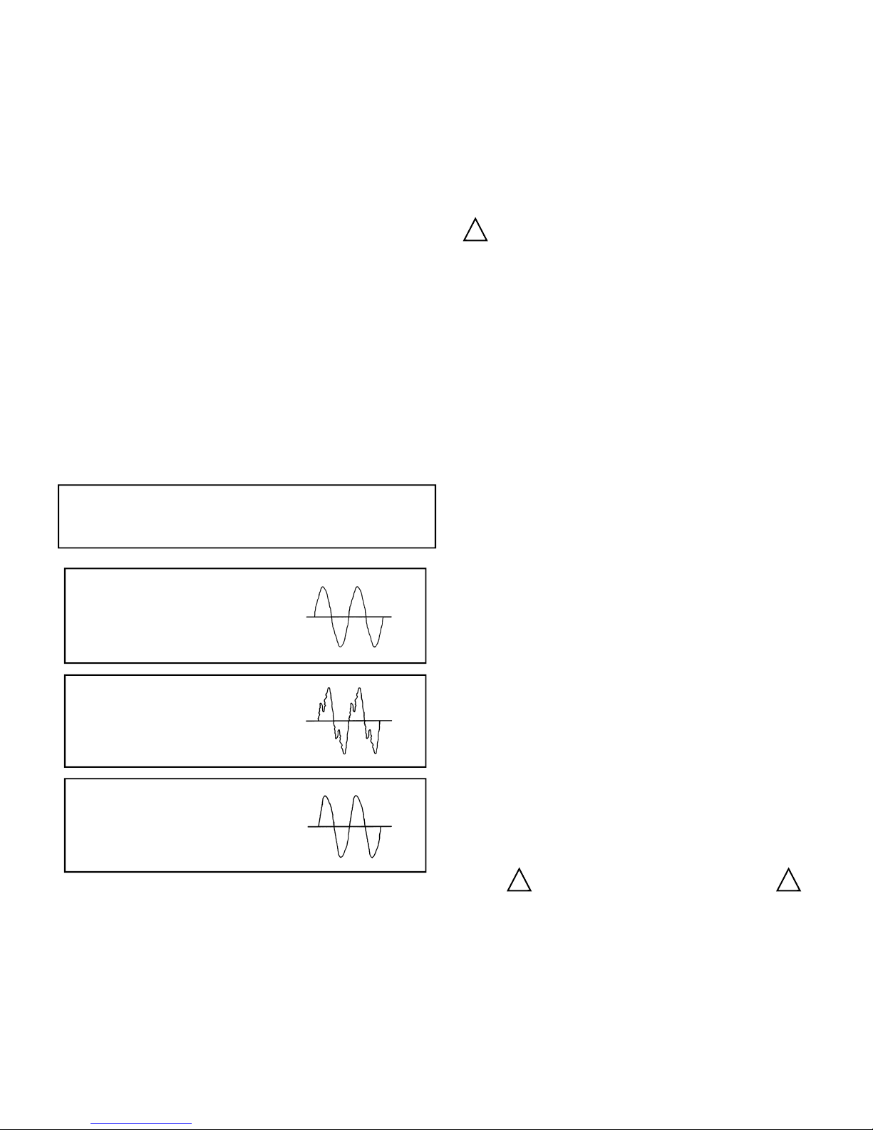
wave-form". Electric current is measured in hertz, the
international unit of frequency, and it equals 60 cycles per
second. A single cycle is called a wave-form and is
graphically displayed to show how clean, or distortion free,
electric power can be.
CAUTION: Always make sure that the emergency electric
power source produces no more than 10% harmful
harmonic wave-form distortions or possible load damage
may occur.
A typical commercial power
wave-form looks like this:
with wave-form distortion of
3% to 5% and is safe for
all electric loads.
A typical generator set
wave-form looks like this:
with wave-form distortion of
25% to 35% and is not
safe for any voltage
sensitive loads.
Your Gillette generator
with "Kleen-Power" has
a wave-form like this:
with wave-form distortion of
7% to 8% and is safe for all
plugged-in electric loads.
E. "SPEED-MATIC" automatic engine idle speed device.
This item is factory installed only, and at "no load"
condition will control engine speed at approximately 2600
to 2800 RPM at 75 to 80 VAC. When an electrical load of
l00 watts or more is introduced into the circuit, the engine
will automatically speed up to the required 3600 RPM and
produce either the full l20 VAC or 240 VAC required
voltage. This device saves wear on the engine and
reduces fuel consumption when you have to let the engine
run at long periods of time but only occasionally are you
going to use power. A switch is also included to by-pass
the entire device allowing set to run at full speed when
electric loads are to be used either frequently or
constantly.
!
F. Manual Transfer Switch allows generating set to be
used for stand-by power. This device will not allow
emergency generating power and normal commercial
power to be connected to the electrical load at the same
time. Upon power failure, the generating set must be
manually started, and the transfer switch must be
operated manually.
G. LOW OIL SHUT DOWN PROTECTION. All sets
have this feature and if oil level falls below safe level, the
engine will shutdown and will not start until proper oil
level is restored.
!
Starting battery for electric start generator sets
will be furnished by user. These starting batteries vary in
size and power output. Consult the chart information
found on battery base as attached to each gen-set for
correct size for your set. Most batteries are wet charged
and ready to use; but you may find a battery that is dry
charged and must have electrolyte acid installed. This
acid is not furnished with set.
CAUTION: If battery acid is ever required, battery must
be brought to a full charge by commercial battery charger
for 24 hours. Use extreme caution when handling the
batteries. Battery acid is extremely dangerous and can
cause severe burns to the eyes, skin, and clothing.
Flush contaminated areas immediately with water, then
call your doctor.
All electric start engines include a built-in battery charger
which operates automatically when the engine runs.
Provisions must be made to keep battery fully charged if
the engine will not be run frequently as in the case of a
permanent stand-by set. This can be accomplished by a
small commercial battery charger connected to battery
and plugged into normal power.
CAUTION: Overcharging the battery will cause battery
damage. Always use an automatically regulated charger
so that as battery becomes charged, the rate of charge is
automatically reduced. Check battery cells with a
hydrometer. The specific gravity of each cell should be
l.280 at 75 F. If cells are low, add distilled water and
recharge battery. Keep battery and battery terminals
clean and dry. Terminals should have light grease or
petroleum jelly applied to retard corrosion.
Disconnection or connection of battery terminals while
engine is running will cause violent spark and may result
in explosion. Never smoke or use open flame near
battery. The area of battery use must be well ventilated
because batteries give off a poisonous and explosive gas
when being charged.
H. Each extended run fuel tank has a separate fuel valve
underneath tank. Always shut this valve off when
generator is not in use.
I. 50 Hertz winding is special; usually for generating sets
to be sent to foreign lands. The operating speed is
reduced to 3000 RPM and normal wattage rating is
reduced by l5% to accommodate this winding.
SAFETY IN REVIEW:
! !
A. Guard yourself against electric shock; avoid personal
contact with live terminals, wires and receptacles. The
electric output voltage in your generator can produce a
fatal shock.
B. Always use approved 3-prong grounded plugs and 3wire cords.
C. The generator must be properly grounded . There is a
labeled ground lug on each set for connection to #8
copper wire attached to suitable ground to earth.
Page 5
Page 7

D. Operation of this set in an enclosed compartment of a
recreational motor home, of other types of vehicle
compartment, enclosed space or poorly ventilated area, is
not recommended and will cause a potential fire hazard
and/or personal health or death hazard by poisonous
fumes.
E. Gasoline and other fuels will always present a hazard
of explosion or fire. Keep correct type fire extinguisher
close by generating set, and consult local fire department
on handling and storage of dangerous fuels.
F. Battery acid can produce skin, eye, and clothing
damage. Batteries emit a hydrogen gas when being
charged. This gas is poisonous and highly explosive. Use
extreme caution when handling batteries.
G. California proposition 65 warning: This is a warning
to user that all exhaust fumes from this engine contain
chemicals known to cause cancer, birth defects, or other
reproductive harm. Do Not Breathe
exhaust fumes.
H. All wiring must conform to national electric code as well
as state and local codes when using generating set as
emergency home or business standby power set. You
must consult and employ a qualified licensed electrician for
safe, hazard and shock-proof installation. Installing a
home or business emergency power system to your
existing wiring circuits is not a "do-it-yourself" project.
I. User must supply battery for energizing engine electric
starter motor. Be sure battery connections are of correct
polarity. All electric start engines use negative ground, l2
V DC battery with minimum size of 45 amp-hour rating, or
minimum 230 cold cranking amp size, 8 HP through 25 HP
gasoline engines... All diesel engines should have
minimum 60 amp-hour or 400 cold cranking amp size
battery. When connecting or disconnecting battery cables,
engine must not be running or cranking.
J. Always shut the engine down completely before filling
engine fuel tank. Never try to fill fuel tank while engine is
in operation, or when viewing conditions are limited. Only
fill tank to 3/4 full. Never fill tank to full level.
K. Before transporting generator in vehicle, drain or run
out all fuel. This prevents possible fuel leakage.
L. Engine should be refueled in a well lighted area. Avoid
fuel spills. Do not operate generator set where fuel spills
have occurred until all excess fuel is cleaned up and
removed. Avoid refueling near open flames, sparking
electric devices, power tools, other high heat conditions or
while the set is running.
M. Good ventilation is mandatory for safe generator
operation. Avoid areas when fuel vapors and exhaust
gases can be trapped: basements, boat bilges,
compartments, garages, etc. Proper air flow and
temperatures are important for safe operation of air-cooled
sets. Never operate generator set when temperature
exceeds 110° F.
N. Muffler and air cleaner should always be installed and
in good condition. They act as a flame arrestor if
backfiring occurs.
O. A spark arrestor muffler must be used when gen-set is
operated around or near flammable materials such as farm
crops, grain dust, forests, brush, dry grass, and other
similar flammable items to help prevent fires caused by
potentially hot engine carbon sparks exiting through
muffler. California statutes #l34005(6), 442, and 443
legally require the use of this item on all portable gen-sets.
It is required on all U.S. Forest Service lands and may also
be required by various other states' statutes and
ordinances.
poisonous engine
P. The gasoline container, used to fill generator fuel
tank, must be an approved tank for this application.
Always use a small container, not over two (2) gallon
capacity. Make sure the container is vented. Open the
vent and the pour nozzle while the gasoline container is
on the ground. Proceed to fill fuel tank while engine is
stopped. Avoid carrying opened gas tank over three (3)
feet in length. Do not drop gasoline tank. Follow all
recommendations from gasoline tank manufacturer in the
use of their product. Do not try to refill gasoline tanks
when temperature exceeds l00 F/40 C.
Q. Some generator models are equipped with automatic
GFCI receptacles. If a ground fault exists (potential
electric shock hazard), the receptacle will not produce
power. When ground fault condition is removed,
manually reset built-in circuit breaker. For maximum
protection against electric shock hazard, manually
operate test switch on GFCI protected receptacle, while
gen-set engine is running and before electric load is
applied to receptacles.
R. Always read engine manual thoroughly before initial
start of your new gen-set. The engine is not considered
broke-in until 25-35 hours run time has passed.
S. High altitude and high tempatures create a negative
effect on engines and can severely reduce engine horse
power, therefore reducing electric power output.
T. Clean, high octane lead free fuel is always
recommended to develop peak horsepower in small
engines. Never use old, stale fuel, or leaded fuel.
U. All engines comply to existing EPA regulations for
maximum toxic exhaust fumes as of September 1997.
V. Consult with licensed electrician on proper grounding
procedures as outlined in National Electric Code (NEC)
article 250-5.
W. All generators have been factory load tested. All
engines are “green” and have not had the (50) hour
break in time to develop peak horsepower. Engine
horsepower ratings meet SAE-J1349 test codes which
specify reduced ratings of 3 1/2% for each 1000 feet over
328 feet above sea level and 1% reduced rating for every
10°F (5.56°C) rise above 77°F (25°C).
Thank you for purchasing this GILLETTE GENERATOR.
It has been designed to yield years of trouble free
service, even in the most abusive conditions. If you have
any further questions, please call, write, or fax us,
attention Christopher Habic or Charles Habic.
GILLETTE GENERATORS
1340 WADE DRIVE
ELKHART, INDIANA 46514
TEL. (574) 264-9639 FAX (574) 262-1840
Internet Site: http://www.gillettegenerators.com
E-mail: [email protected]
Page 6
Page 8

GILLETTE GENERATORS
GILLETTE GENERATORS, INC. — 1340 WADE DRIVE · ELKHART, INDIANA 46514 · TEL: (574) 264-9639 · FAX: (574) 262-1840
VISIT OUR INTERNET SITE AT: http://www.gillettegenerators.com · E-MAIL: [email protected]
PGOG1/PORTABLES/GASOLINE
GIL-OWN-725-20090908
... in portable, stationary and standby- powerplant packages.
 Loading...