

Gilian LFS-113 Instruction Manual
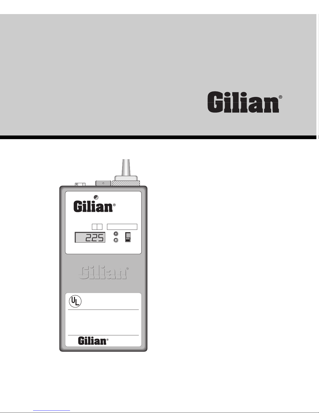
LFS-113
Dual Mode Low Flow Air Sampler
1–350 cc/min. Constant Pressure
5–200 cc/min. Constant Flow
LOW FLOW SAMPLER
Patent Pending
MODEL LFS-113DC
TIME (MIN)
FLOW ADJ
DUAL
MODE
S/N–
PN 800098–
ON
OFF
B
F
Made in USA
LISTED 17G9
MODEL LFS-113D / LFS-113DC
®
Personal Air Sampler
Intrinsically Safe Portable Air Sampling Pump for use in
Hazardous locations: Class I Groups A,B,C,D; Class II
Groups E,F,G; Class III. Temperature Code T3.
WARNING
Substitution of components may impair Intrinsic Safety.
Use only with UL Listed Portable Air Sampling Pump
Battery Pack.
INSTRUCTION MANUAL
NOTE: Please read all warnings and instructions before operating this unit. Failure to follow these
instructions and procedures can result in permanent damage to the equipment.
WARNING:
This unit is designed specifically for use with Gilian LFS-113, UL, and SCS intrinsically safe battery
packs and equipment. The unit should only be operated in environments that the unit's intrinsic safety
labeling permits. Do not operate in excessive chemical or water vapor atmospheres. Do not charge
sampler outdoors or in a damp environment. Use specified Gilian chargers only when recharging the
battery system. Use of any other charger may short out the battery or cause permanent damage to the
electrical system. Do not leave unit charging for more than 16 hours. Overcharging cells may cause
overheating and subsequent damage to/or decrease in battery life and performance.
Sensidyne, Inc.
16333 Bay Vista Drive • Clearwater, FL 33760
800-451-9444 • 727-530-3602
FAX 727-539-0550

Operating manual for the
LFS-113 Air Sampling System
Includes models:
LFS-113D, LFS-113DC
Table of Contents
Sec. Title Page
WARRANTY/SERVICE INFORMATION 2
Fig. 1 - Flow/Timing Capabilities/Approvals 4
1.0 INTRODUCTION 5-8
1.1 Theory of Operation 5
1.2 General Description, nomenclature6
Fig. 2 - Sampler front, side & top 7
Fig. 3 - Sampler back & side 8
2.0 SET-UP 9
2.1 Charging 9
2.2 Filter Check 9
3.0 OPERATION 9-12
3.1 Mode Selection 9-10
3.2 Constant Flow Sampling 10-11
3.3 Multiple Flow Sampling 11-12
4.0 PERFORMANCE CHECKS 12-13
4.1 Constant Flow Check 12
4.1.1 Pressure Fault Check 12
4.1.2 Pressure Fault Clear Check 12-13
4.1.3 Battery Performance Check 13
4.2 Constant Pressure 13
4.2.1 Constant Pressure Check 13
5.0 MAINTENANCE 13-14
5.1 Battery Charging and Storage 13-14
5.2 Replacing the Battery 14
5.3 Changing the Pump Filter 14
Fig. 4 - Constant flow mode set-up 15
Fig. 5 - Multi-flow mode set-up 16
Fig. 6 - Pump test set-up 17
6.0 SPECIFICATIONS 18

Figure 1
Flow/Timing Capabilities/Approvals
page 4
INTRINSIC SAFETY APPROVALS
See product labeling for specific intrinsic safety approvals.
UL
®
(Underwriters Laboratories, Inc.)
All LFS-113 series pumps are UL approved intrinsically safe for use in hazardous locations Class I, Groups A, B, C, & D, Class II, Groups E, F, & G and Class
III.
UL listed 17G9, Temperature Code T3C.
MSHA
®
(Mine Safety and Health Administration)
The designs of this air sampling pump meets the requirements of title 30 code
of Federal Regulations Part 18 and are hereby approved as permissible for use
in gassy mines, when used with a specified Gilian Battery pack
SCS
®
(SIRA Certification Service), Europe
Certificate No. Ex90C2011X, Coding: EEx iB IIC T4
ISO 9002 Quality Assurance Standard, International
All Gilian products are designed, manufactured and produced in accordance
with and comply with the ISO 9002 international quality assurance standard.
SWOLFWOLGNIMIT
ledoM
noitangiseDnoitangiseD
noitangiseD
noitangiseDnoitangiseD
tnatsnoC
wolFwolF
wolF
wolFwolF
tnatsnoC
erusserPerusserP
erusserP
erusserPerusserP
despalE
emiTemiT
emiT
emiTemiT
kcolCkcolC
kcolC
kcolCkcolC
tnatsnI
tluaFtluaF
tluaF
tluaFtluaF
noitcnuFnoitcnuF
noitcnuF
noitcnuFnoitcnuF
tnebroS
ebuTebuT
ebuT
ebuTebuT
rekaerBrekaerB
rekaerB
rekaerBrekaerB
D
•••••••••••••••
CD
•••••••••••••••••••••••••

page 5
1.0 INTRODUCTION
The LFS-113 series sampler provides a rugged, reliable and compact sampling
system for industrial hygiene and environmental sampling employment of single or
multiple sorbent tubes and gas sampling bags. Two low flow modes of sampling
allowconstant flows from 5-200 cc/min., as well as constant pressure for multiple
sorbent tube sampling from 1-350 cc/min. (combined flow rates). A compact and
lightweight sampler, the LFS combines convenience and useful functions for accurate
sampling.
1.1 Theory of Operation
The LFS low flow sampler offers two modes of sampling which are easily activated
by turning the selector dial located at the back of the sampler. A hex wrench is inserted
and turned to the desired position and a visual indicator displays the mode being used.
The sampler is turned on and will run continuously until manually shut down. An
optional LCD clock is available on DC models which offers elapsed run time and an
instant-fault function.The constant pressure (multi-flow) mode when used with a
multiple flow controller tube holder, offers a multi-tube sampling capability that is
adjusted individually at each tube position.

page 6
1.2 General Description (see figures 2 and 3)
Item Nomenclature Description
1 Charging Jack Receptacle provides means of connecting charger for recharging
internal battery pack.
2 Pump Filter 10 Micron Nylon filter protects pump assembly from dirt. Discolora-
tion indicates need for filter replacement.
3 Mode Indicator Visually confirms mode engagement via Black or White indication.
4 Mode Select Provides means of unlocking, indexing and re-locking mode selector
valve to change from constant low flow to the multiple low flow mode.
5 On/Off Switch Activates sampler operation.
6 Battery Check Green LED indicates sufficient battery power to run the pump for an 8-
hour period under normal load conditions.
7 Fault Indicator Indicates flow fault due to excessive pressure or insufficient battery
voltage to maintain flow.
8 Clock Display Indicates continuous run-time in minutes which will lock in the sample
(DC models only.) time upon fault indication. Time will reset to zero when the power
switch is turned OFF and back ON.
9 Flow Adjust Provides external means of adjusting the air flow rate.
10 Inlet Boss Air inlet is located on the clear filter housing and provides built-in
means of attaching tubing for suction sampling.
11 Outlet Port Receptacle for discharge air boss accessory. The cap screw prevents
dirt from entering the dischargeoutlet when not in use.
12 Discharge Boss An accessory which when installed into the discharge outlet, provides a
means of filling air sampling bags.
13 Belt Clip Built-in means of attaching sampler to worker’s belt.
14 Case Screws (4) Holds battery pack in place as well as case front and back.
15 Battery Pack Provides DC power to operate the unit.
 Loading...