

Gilian Gilibrator Instruction Manual

Instruction Manual
for the
Gilian”
Primary Standard Airflow Calibrator
with Interchangeable Flow Cell Assemblies
Flow Cell Assembly Ranges
Low : 1 to 250 cc/min.
Standard : 20 cc/min. to 6 LPM
High : 2 to 30 LPM
On-Site Instruments
l-8OO-7-On-Site
(l-800-766-7483)
689 North James Road - Columbus, Ohio 43219
Advanced Test Equipment Rentals
www.atecorp.com 800-404-ATEC (2832)
®
E
s
t
a
b
l
i
s
h
e
d
1
9
8
1
Prologue
This Instruction Manual describes the basic principles, installation,
operation/controls and maintenance for the Cilibrator, Primary Standard
Airflow Calibrator manufactured by Cilian Instrument Corp.
Table of Contents
The Gil ibrator
Section #
Page #
1
Introduct ion
2
2
General Description 2-6
3
Theory of Operation
7
4
Operating Procedures
8-12
Initial Set-up & Operation
5
Storage E Maintenance
13-17
6
The Printer Module
18
Introduction
E
General Description
18-19
Theory of Operation
19
Operation Procedures
19-21
Storage and Maintenance
21
7
Spec
if icat ions
-
The Gil ibrator
22
The Printer Module
23
8
Cilibrator Parts List
23
9
Warranty E Service Policy
24
1
Section 1
Introductih
The Gilibrator is a high accuracy, electronic bubble flowmeter that
provides instantaneous air flow readings and a cumulative averaging of
multiple samples.
The Gilibrator system provides a large dynamic range
through the use of 3 interchangeable flow cell assemblies. A delete
function, on the Control Unit, subtracts eroneous readings to insure
accurate data. The Control unit also supports a hard copy print out through
the use of a printer accessory-.
Section 2
General Description (See fig. la)
The Gilibrator is comprised of the following basic components: Flow
Cell Assembly, Control Unit (base), Battery Charger and Soap Solution. Dif-
ferent sized inter-changeable Flow Cell Assemblies are available for use as
follows:
Low Flow : 1 to 250
cc/min.
Standard Flow : 20
cclmin
to 6 LPM
High Flow : 2 to 30 LPM
In addition to the basic components, an optional Printer Module is
available. The printer provides a hard copy record of calibration data,
however, identical data is displayed on the LCD of the Cilibrator Control
Unit during calibration.
1. Flow Cell Assembly (See fig. lb)
The Flow Cell Assembly consists of a Bubble Generator and Sensor
Block. Each Bubble Generator is sized to produce a bubble film stretched
across the diameter of the flow cell tube which is carried by airflow from
the bottom to top of the tube. As the bubble traverses past two infrared
sensors, each sensor transmits a signal to the Control Unit (base) indicating the passage of the film. The Flow Cell Assembly incorporates a manual
bubble initiation push button which starts the film on its travel up the
tube.
A. Bubble Generator
1) Flow Ranges
Low Flow
: 1 to 250
cclmin.
Standard Flow
: 20
cc/min
to 6 LPM
I
High Flow
: 2 to 30 LPM
2) Pulsation Damper (2) - a built-in damper smoothes out any
pulsation’ within the airflow and reduces occilation of the bubble
film assuring maximum accuracy.
3) Bubble Initiate Button (22) - This pushbutton lowers the Bubble
Generator Ring (21) into the soap solution reservoir. Upon
releasing the button, the ring lifts out of the soap solution and
a film bubble is generated across the opening of the flow tube
(241.
2
4) Bubble Breaker (4)- The Bubble Breaker is a secondary chamber
in the upper chamber which provides the soap film a rapid expan-
sion path which is instrumental in breaking the bubble. ‘This
prevents excessive wall wetting by the soap film and allows it to
flow back into the cell.
5) Storage Tubing (25) - This anti-spill tubing connects upper and
lower cell chambers and prevents the soap solution from evaporating which may cause the solution concentration to change.’
CAUTION: If transporting by plane, be sure to disconnect this hosing from
upper or lower Flow Cell Chamber Bosses (23 & 26) to prevent pressurization
and possible rupture within the Bubble Generator.
8.
Sensor Block (8)
Surrounding the flow tube
(24),and
secured between the upper and
lower chamber of the bubble generator, is the Sensor Block (8).
The blockincorporates lower and upper sensors for time start and
time stop. Thesensors consist of an infrared emitter and detector
pairs whose sensitivity and accuracy is controlled by a “columna-
ting slot”. This block is secured to the Bubble Generator
Assembly (1) by means of two Locking Screws ((7) and allows easy
removal to facilitate cleaning.
1) Electrical Interface -The Electrical Interface provides power
to the sensing system as well as transmits timing information to
the Control Unit.
2. The Control Unit (base) (See fig. la)
The Control Unit (14) contains a crystal controlled timing system,
a micro processor control system,
and an LCD readout for displaying
flow and messages. The Control Unit also contains switches for Reset
(17),
Delete (16) and Auto-Averaging (15) functions as well as an
Printer Jack (18) interface port for direct connection to a hard copy
printer. LED indicators are provided to note Charging (11) and Run
calibration (20) operation.
a) Power (12) - switch turns the Control Units power on and off.
b) Charge Indicator LED (11) - lights when the charger is plugged
into the Charging Jack
c) Printer Jack (18) - provides interface for auxillary printer.
d) Reset (17)
-
push button deletes all current information for
themicro
processor in order to initiate a new sequence.
e) Delete (16) - push button automatically deletes false informa-
tion from the average and will reset the average and sample number
to the previous reading.
When a printer is in line, this will
indicate a minus symbol and the average will return to the
previous value.
3
f)
Average (15)- push button when pushed and held will display
the average of the previous sequence of readings. When released
will display the last actual reading and when re-pushed and held,
will show the numbe,r of samples in the sequence with display
information (S=sample #). Releasing the button will automatical-
ly bring the display back to the last reading.
g) Sequence Run Indicator LED (20) - indicates bubble sequence by
lighting as the bubble passes between the two sensors. The LCD
(19) will be blank. The Run signal will also light when turning
on the Control Unit and will extinguish after unit has finished
it’s initial sequence check.
h) Low Battery - will indicate on the LCD display (19) if insuffi-
cient battery voltage is available to operate the unit proper-
ly. Since power for all Control Unit functions is derived from the
rechargeable ‘NiCad battery, the batteries must be fully charged
for proper operation. A “Low Battery” indication will also appear
initially when turning the Control Unit ON as a sequence check of
the unit’s electronics.
i)
Cable Assembly (5) - mates with the Connecting Jack (6) in the
back of the Sensor Block. It provides power for the sensing
system, information regarding cell size , and control of the
timing information to the micro processor.
j)
Timing System - The quartz controlled timing‘system controls
infra-red sensor activation to assure maximum calculation
accura-
CY.
k) Micro Processor - controls the timing and mathematical data
processing to provide optimum flow measurement characteristics.
This programmable micro processor can be upgraded as new programs
become available.
3. Battery Charger
Standard wall operated 120V charger to charge Gilibrator Control
Unit for 14 hours prior to operation. The Charging LED on the Control
Unit will be illuminated while
,charging
is in progress.
4. Soap Solution
This specially compounded low residue soap is specifically
designed to provide high film strength and compatibility with the
materials used within the Flow Cell Assembly.
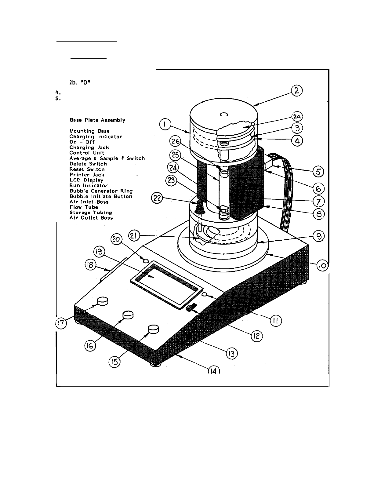
The Gilibrator System
The Gilibrator
Nomenclature
1.
2.
3.
::
6.
7.
6.
9.
10.
11.
12.
13.
14.
15.
16.
17.
16.
19.
20.
21.
22.
23.
24.
Bubble Generator Assembly
Damper Plate
2a. Pulsation Damper
2b.
“0” Ring
Spacer
Plate, Bubble Breaker
Cable Assembly
Sensor Block Connecting Jack
Sensor Block Locking Screw
Sensor Block
25.
26.
Figure la
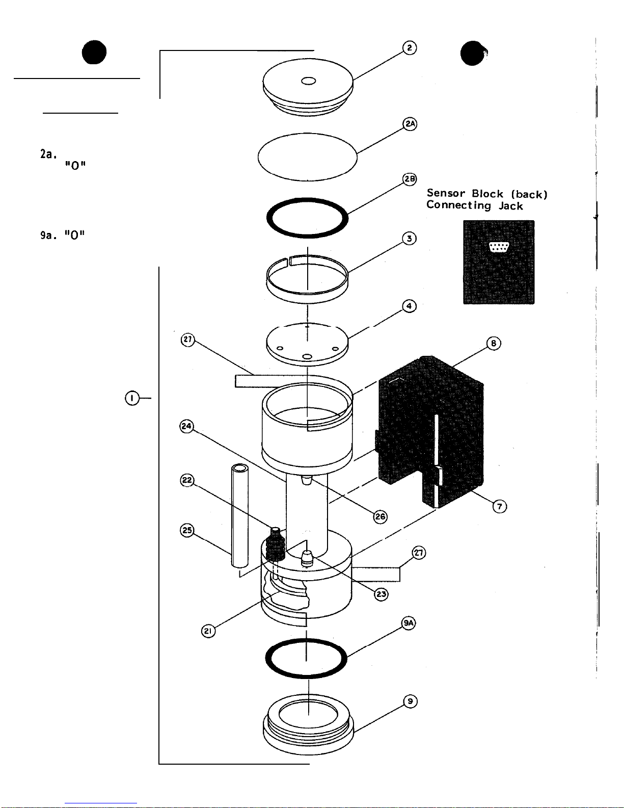
The Gilibrator System
The Flow Cell Assembly
Nomenclature
I
I
Bubble Generator Assembly
Damper Plate
2a. Pulsation Damper
2b.
“0”
Ring
Spacer
Plate, Bubble Breaker
Sensor Block Locking Screw
Sensor Block
Base Plate Assembly
9a.
“0”
Ring
Bubble Generator Ring
Bubble Initiate Button
21.
22.
23.
Air Inlet Boss
24.
Flow Tube
25. Storage Tubing
26.
Air Outlet Boss
27. Safety Tape
1.
2.
3.
4.
7.
a.
9.
a---
6
Figure lb
w
Section 3
Theory of Operation
1. Primary Airflow Standard
To be a primary standard, all values must be absolute and measured as
absolute. A primary standard airflow measurement is a volume divided by a
time interval as performed by the Control Unit of the Gilibrator. The
volume, V, is measured volume of space between two infrared sensors. The
time is that interval needed for a soap film bubble to traverse between the
two sensors which bound the volume.
Therefore,
V/t,
the volume per unit of
time, becomes the airflow and is prime because all measurements are basic...
volume and time. In today’s technology, time is measured by an electronic
clock whose accuracy exceeds that of volume measurements by orders of
magnitude, hence, the control accuracy volume resides solely with volume
measurements.
2. Bubble Generation and measurement
a) The Gilibrator consists of two elements, the Flow Cell Assembly and
the Control Unit (base). The function of the Flow Cell Assembly
-is
to
generate a clean consistent bubble which traverses up the flow tube. Meas-
urement of the traverse time is done by infrared sensor pairs which are
mounted at the bottom and the top of the Sensor Block. The volume bound by
these sensors is specifically adjusted to a volume standard by allowing the
upper sensor blocks to move in unison so as to enable this calibration to be
set accurately to a primary volume standard,
A second function of the
sensor block provides the interfacing code to define the cell volume as well
as sensitivity adjustments for the optical sensor systems.
b)
As the bubble traverses between the sansors, first one and then the
second, sensors are tripped thereby providing the time for the bubble
traverse.
This timing information is sent to the micro processor of the
control base which in turn provides the crystal control time base for the
system.
The timing information along with the volu,me information are then
sent to the micro processor which in turn does the necessary mathematical
calculations which allow the flow to be displayed directly on the LCD
readout. In order to insure the highest accuracy possible, a Delete and
Average function are provided on the Control Unit. The Delete allows for
subtracting out an obvious malformed bubble and the average allows the user
to obtain average information without pencil or paper. A printer interface
allows connection of a Printer Module so that hard copy can be produced.
 Loading...