

Gilian Gilair Plus Operation Manual
Operation Manual
1000 112
(800) 451-9444 • +1 (727) 530-3602
www.Sensidyne.com • info@Sensidyne.com
REF 360-0132-01 (Rev T, Software version 2.4.0)
TH
Circle N, Suite 100 • St. Petersburg, FL 33716 USA
Page II
Gilian GilAir® Plus Air Sampling Pump – Operation Manual
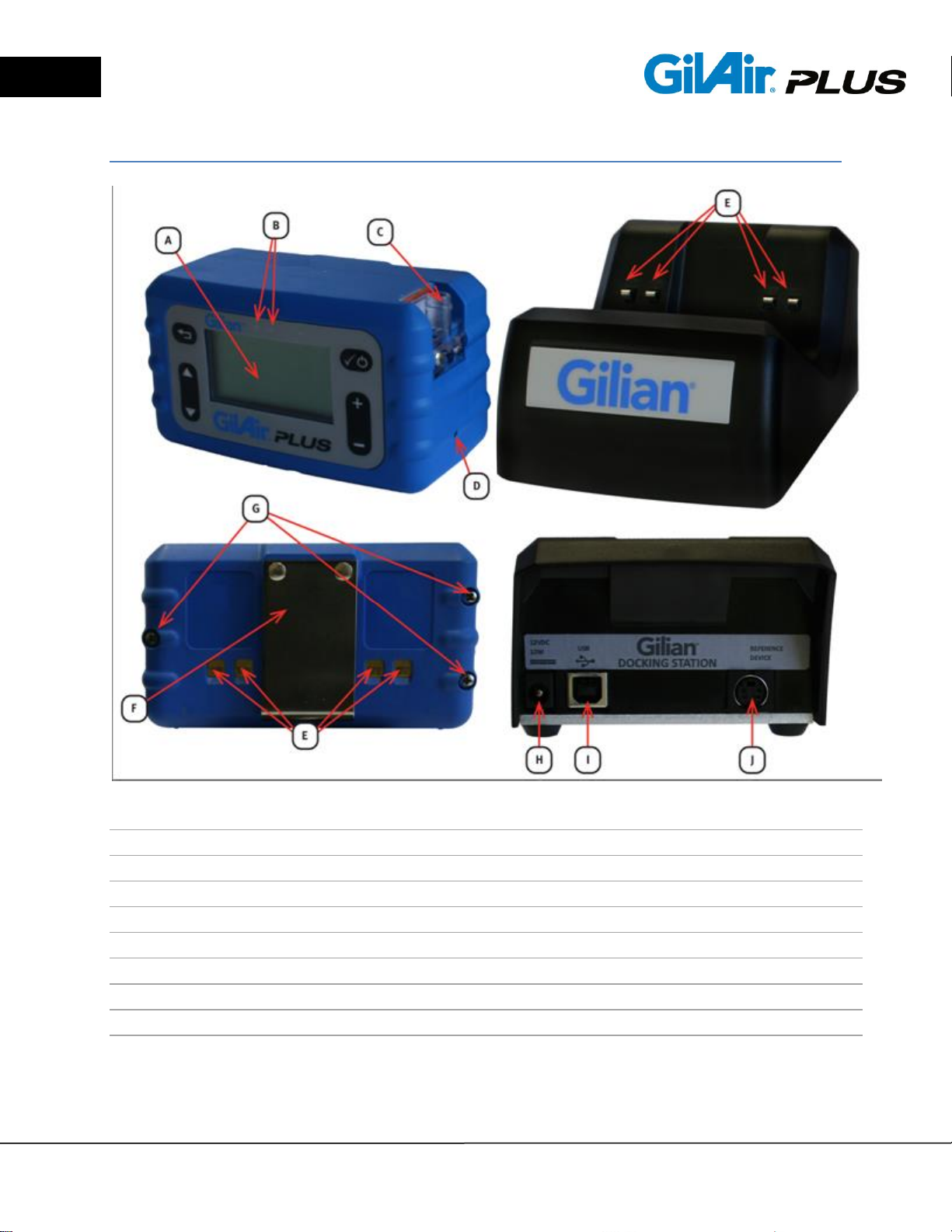
GilAir Plus Identifiers:
A LCD Display
B Status and Notification LED’s
C Inlet Filter
D Hi/Lo Control Valve
E Charging Contacts
F Belt Clip
G Battery Access Screws
H Power Port
I USB Port (On communication-enabled Docks)
J Reference Device Port (On communication-enabled Docks)
© 2015 Sensidyne, LP Sensidyne Document No. 360-0132-01 (Rev T, Software version 2.4.0)

Page III
Gilian GilAir® Plus Air Sampling Pump – Operation Manual
Quality Policy Statement
At Sensidyne, we are committed to providing products and services that
consistently meet customer needs and comply with all applicable
statutory and regulatory requirements.
Our products are designed, manufactured and calibrated in accordance
with ISO 9001:2008, ISO/IEC 17025:2005, ISO/IEC 80079-34, ATEX
Directive 94/9/EEC, and IECEx, where applicable. Through ongoing
review of our designs, supplier performance, and customer feedback we
strive to ensure continuous improvement.
All employees at Sensidyne share the responsibility to provide products
that are produced efficiently and economically representing the best
value to our customers. We are committed to meeting or exceeding
customer expectations in everything we do.
Sensidyne, LP
Sensidyne Document No. 360-0132-01 (Rev T Software version 2.4.0) © 2015 Sensidyne, LP

Page IV
Gilian GilAir® Plus Air Sampling Pump – Operation Manual
Warranty
Sensidyne warrants that, at the time of delivery, the GilAir Plus shall be free of all
defects in workmanship and material. Sensidyne will repair or replace, at its sole
option, any GilAir Plus found to be defective by Sensidyne, if notified by Purchaser
within the Warranty time period.
The warranty time period shall be for two (2) years from the date of original shipment by
Sensidyne, except as noted below.
A. Exceptions to the above two year warranty time period:
1. The keypad of the GilAir Plus has a five (5) year warranty
2. The rechargeable NiMH battery pack has a one (1) year warranty.
3. Consumables have a ninety (90) day warranty.
B. This warranty shall be null and void on any product which:
1. Is operated or used in excess of the product’s operating specifications; or
2. is not properly maintained in accordance with its maintenance manual or
specifications; or
3. has been repaired or modified by persons other than authorized Sensidyne
personnel or Factory Trained Service Centers, unless such work is authorized in
advance in writing by Sensidyne; or
4. has been damaged, abused, or misused.
C. Warranty on Service and Repairs:
1. Goods, which have been repaired or replaced during the warranty period, are
warranted only for the remainder of the unexpired portion of the original warranty
period.
2. Repairs or service provided not pursuant to warranty: 180 days from date of
shipment by Sensidyne.
THIS WARRANTY IS IN LIEU OF ALL OTHER WARRANTIES, EXPRESSED OR
IMPLIED, INCLUDING BUT NOT BEING LIMITED TO THE IMPLIED WARRANTIES
OF MERCHANTABILITY AND FITNESS FOR USE FOR A PARTICULAR PURPOSE,
WHICH ARE EXPRESSLY DISCLAIMED, AND CONSTITUTES THE ONLY
WARRANTY OF SENSIDYNE WITH RESPECT TO GOODS SOLD OR DELIVERED.
© 2015 Sensidyne, LP Sensidyne Document No. 360-0132-01 (Rev T, Software version 2.4.0)

Page V
Gilian GilAir® Plus Air Sampling Pump – Operation Manual
Table of Contents
GilAir Plus Identifiers: .................................................................................................. II
Quality Policy Statement ............................................................................................ III
Warranty ..................................................................................................................... IV
SECTION ONE: Preface ............................................................................................ 1
WARNINGS ................................................................................................................ 3
Certifications, Approvals and Compliances ................................................................. 5
SECTION TWO: Introduction ..................................................................................... 6
2.1. Product Description .......................................................................................... 6
2.2. Pump Kit Descriptions ...................................................................................... 7
SECTION THREE: Set-Up ......................................................................................... 8
3.1. Preparation ....................................................................................................... 8
3.2. Pump Start Up .................................................................................................. 8
3.2.1. Power Up .................................................................................................... 8
3.2.2. Startup sequence ........................................................................................ 8
3.2.3. Power Source Check .................................................................................. 9
3.2.4. Power Down ................................................................................................ 9
3.3. Setting the Flow Rate ..................................................................................... 10
3.4. Power Options ................................................................................................ 10
SECTION FOUR: General Operation ....................................................................... 11
4.1. Overview ........................................................................................................ 11
4.2. Connections ................................................................................................... 11
4.3. Navigation ...................................................................................................... 12
4.4. Menus ............................................................................................................. 12
4.5. Displays .......................................................................................................... 14
4.5.1. Display Details .......................................................................................... 16
4.5.2. Menu Details ............................................................................................. 16
4.5.3. Idle Display Details .................................................................................... 16
4.5.4. Constant Flow Run Display Details ........................................................... 17
4.5.5. Constant Pressure Display Details ............................................................ 17
4.5.6. Fault Display Details ................................................................................. 18
4.5.7. Program Display ........................................................................................ 18
4.5.8. STP Display .............................................................................................. 18
Sensidyne Document No. 360-0132-01 (Rev T Software version 2.4.0) © 2015 Sensidyne, LP

Page VI
Gilian GilAir® Plus Air Sampling Pump – Operation Manual
4.5.9. Barometric Compensation Display ............................................................ 19
4.6. Sensor Calibration .......................................................................................... 20
4.7. Run Mode ....................................................................................................... 20
4.7.1. Run Mode Descriptions ............................................................................. 20
4.7.2. Locking the Keypad ................................................................................... 21
4.7.3. Unlocking the Keypad ............................................................................... 21
4.8. Flow Set (cc/min) ............................................................................................ 23
4.8.1. Setting the Flow Rate Range .................................................................... 23
4.8.2. Setting the Flow Rate ................................................................................ 24
4.9. Field Calibrate ................................................................................................ 24
4.9.1. Field Calibration ................................ ........................................................ 24
4.9.2. Calibration Option (SmartCal
SM
) ............................................................... 25
4.9.3. Displayed Flow Calibration ........................................................................ 26
4.10. Fault Condition Cause and Displays ............................................................... 27
SECTION FIVE: Options .......................................................................................... 29
5.1. Setup ► ......................................................................................................... 29
5.2. Event ID Enable .............................................................................................. 29
5.3. Pre/Post-Calibration ....................................................................................... 30
5.4. User Mode ...................................................................................................... 32
5.5. Power-on Run ................................................................................................. 32
5.6. Event Lock ...................................................................................................... 32
5.7. EN13137 ........................................................................................................ 32
5.8. Fault Retry ...................................................................................................... 33
5.9. Valve Mode .................................................................................................... 33
5.10. SmartCalSM Automatic Calibration .................................................................. 33
5.10.1. Gilibrator-2 ................................................................................................ 34
5.10.2. Challenger® ............................................................................................... 36
5.10.3. TSI™ Model 4146 and Sensidyne Go-Cal ................................................ 37
5.10.4. Bios Defender™ 510, 520, 530 ................................................................. 38
5.11. Clear Datalog .................................................................................................. 39
5.12. Run Options ► ............................................................................................... 40
5.12.1. Standard Temperature (STP Models only) ................................................ 40
5.12.2. Standard Pressure (mmHg) (STP models only) ........................................ 40
5.12.3. Sensor Option ........................................................................................... 41
© 2015 Sensidyne, LP Sensidyne Document No. 360-0132-01 (Rev T, Software version 2.4.0)

Page VII
Gilian GilAir® Plus Air Sampling Pump – Operation Manual
5.12.4. PaTa compensation (STP models only, in high flow) ................................ 41
5.13. Display Options ► .......................................................................................... 42
5.13.1. Language .................................................................................................. 42
5.13.2. Temperature Units .................................................................................... 42
5.13.3. Pressure Units ........................................................................................... 43
5.14. Clock Set ► .................................................................................................... 43
5.14.1. Clock ......................................................................................................... 43
5.14.2. Date .......................................................................................................... 44
5.14.3. Time Format .............................................................................................. 44
5.14.4. Date Format .............................................................................................. 45
5.15. Password ........................................................................................................ 45
5.16. Control Mode .................................................................................................. 46
5.17. Run Mode: Manual, Timed, Vol, RT and Program name ................................ 47
5.18. Run Setup ► .................................................................................................. 48
5.18.1. Timed Start (T/V/R start) ........................................................................... 48
5.19. Timed Duration ............................................................................................... 49
5.20. Vol Set ............................................................................................................ 49
5.21. RT ................................................................................................................... 49
5.22. Pressure Set ("H2O, mmHg, KPa or mbar) ..................................................... 50
SECTION SIX: Programming ................................................................................... 51
6.1. Program ► ..................................................................................................... 51
6.2. Program Edit ► .............................................................................................. 52
6.3. Program Name ............................................................................................... 53
6.4. Control Mode .................................................................................................. 53
6.5. Set the Flow Rate or Pressure ........................................................................ 53
6.6. Program Steps ................................................................................................ 54
6.7. Function .......................................................................................................... 54
6.8. Function Value ................................................................................................ 55
6.9. Save a Program .............................................................................................. 56
6.10. Review Events ................................................................................................ 56
SECTION SEVEN: PC Interface .............................................................................. 58
7.1. PC Interface.................................................................................................... 58
SECTION EIGHT: Maintenance Menu ..................................................................... 59
8.1. Maintenance ► .............................................................................................. 59
Sensidyne Document No. 360-0132-01 (Rev T Software version 2.4.0) © 2015 Sensidyne, LP

Page VIII
Gilian GilAir® Plus Air Sampling Pump – Operation Manual
8.2. Global Reset ................................................................................................... 59
8.2.1. Reset (save programs) .............................................................................. 61
8.2.2. Clear Datalog ............................................................................................ 62
8.3. T ambient Cal ► ............................................................................................. 63
8.4. Barometric P Cal ► ........................................................................................ 64
8.5. Pressure ► ..................................................................................................... 65
8.6. Power Source ................................................................................................. 66
8.7. Contrast .......................................................................................................... 66
SECTION NINE: User Maintenance ......................................................................... 67
9.1. NiMH Battery Maintenance and Reconditioning ............................................. 67
9.2. Battery Replacement ...................................................................................... 68
9.3. Pump Filter Maintenance ................................................................................ 68
SECTION TEN: Appendices .................................................................................... 70
Appendix A: Menu Outline ........................................................................................ 71
Appendix B: Example Program Setup & Edit ........................................................... 73
Appendix C: Barometric Compensation ................................................................... 80
Appendix D: Dual Port High/Low Flow Manifold ....................................................... 81
Appendix E: Troubleshooting Guide ......................................................................... 83
Appendix F: Parts List .............................................................................................. 87
Appendix G: Specifications ...................................................................................... 92
Appendix H: Charging/Communications Dock ......................................................... 95
Appendix I: Factory Calibration and Service .......................................................... 100
© 2015 Sensidyne, LP Sensidyne Document No. 360-0132-01 (Rev T, Software version 2.4.0)

Page 1
Gilian GilAir® Plus Air Sampling Pump – Operation Manual
SECTION ONE: Preface
Proprietary Notice
The intended use of this manual is exclusive to owners of Gilian GilAir Plus air
sampling pumps. The material within this manual is proprietary information and
is to be used only to understand, operate, and service the instrument. By
receiving this document, the recipient agrees that neither this document, the
information disclosed within, nor any part thereof shall be reproduced or
transferred, physically, electronically or in any other form or used or disclosed to
others for manufacturing or for any other purpose except as specifically
authorized in writing by Sensidyne, LP.
Copyright Notice
© 2015 Sensidyne, LP All Rights Reserved. Reproduction, transmittal,
transcribing, storing in a retrieval system or translation of this document in part or
in its entirety is strictly prohibited without the prior written permission of
Sensidyne, LP.
Trademark Notice
Sensidyne, the Sensidyne logo, Gilian, Gilian GilAir, GilAir, and GilAir Plus
names and logos are registered trademarks of Sensidyne, LP. Other trademarks
and service marks used in this document are the property of their respective
companies and are used only for informational and explanatory purposes.
Firmware/Software License
The firmware and the associated PC application software installed in or provided
with the GilAir Plus pump is the property of Sensidyne, LP and shall remain the
property of Sensidyne, LP in perpetuity. The firmware/software is protected by
U.S. and international copyright laws and is licensed for specific use with the
Gilian GilAir Plus pump. The user may NOT reverse-engineer, disassemble,
decompile, or make any attempt to discover the source code of the
firmware/software. The firmware/software may NOT be translated, copied,
merged or modified in any way. The user may NOT sublicense, rent, or lease
any portion of the firmware/software. The right to use the firmware/software
terminates automatically if any part of this license is violated.
Sensidyne Document No. 360-0132-01 (Rev T Software version 2.4.0) © 2015 Sensidyne, LP

Page 2
Gilian GilAir® Plus Air Sampling Pump – Operation Manual
Disclaimer
THE SELLER ASSUMES NO RESPONSIBILITY WHATSOEVER, TO ANY
PARTY WHOSOEVER, FOR ANY PROPERTY DAMAGE, PERSONAL
INJURY, OR DEATH RECEIVED BY OR RESULTING FROM, IN WHOLE, OR
IN PART, THE IMPROPER USE, INSTALLATION, OR STORAGE OF THIS
PRODUCT BY THE USER, PERSON, FIRM, ENTITY, CORPORATION OR
PARTY NOT ADHERING TO THE INSTRUCTIONS AND WARNINGS IN THIS
MANUAL, OR OTHERWISE PROVIDED BY THE SELLER OR FROM NOT
ADHERING TO ALL FEDERAL, STATE, AND LOCAL ENVIRONMENTAL AND
OCCUPATIONAL HEALTH AND SAFETY LAWS AND REGULATIONS.
THE SELLER SHALL NOT BE LIABLE FOR DIRECT, INDIRECT,
CONSEQUENTIAL, INCIDENTAL OR OTHER DAMAGES RESULTING FROM
THE SALE AND USE OF ANY GOODS AND SELLER’S LIABILITY
HEREUNDER SHALL BE LIMITED TO REPAIR OR REPLACEMENT OF ANY
GOODS FOUND DEFECTIVE.
© 2015 Sensidyne, LP Sensidyne Document No. 360-0132-01 (Rev T, Software version 2.4.0)

Page 3
Gilian GilAir® Plus Air Sampling Pump – Operation Manual
WARNINGS
READ AND UNDERSTAND ALL WARNINGS AND INSTRUCTIONS BEFORE USE.
Failure to read, understand, and comply with ALL accompanying literature, instructions,
product labels, and warnings could result in property damage, severe personal injury, or
death.
Read and understand ALL applicable environmental health and safety laws and
regulations before operating this product. Ensure complete compliance with ALL
applicable laws and regulations before and during the use of this product.
DO NOT remove, cover, or alter any label or tag on this product, its accessories, or
related products.
UNDER NO CIRCUMSTANCES should this product be used except by qualified,
trained and technically competent personnel.
The GilAir Plus portable air sampling pump is intended for both indoor and outdoor use.
The unit is not waterproof. NEVER submerge the unit in water. Pump failure, faulting
or user injury may result.
The GilAir Plus Pump is Intrinsically Safe when used with specified battery pack part
number 783-0012-01-R. Refer to the Certifications and Approvals section for approval
ratings. Due to risk of static charge, do not clean the pump labels or keypad with
a dry cloth in areas where acetylene may be present.
DO NOT operate this product should it malfunction, require repair, or have a cracked or
broken case or other visible or known damage.
DO NOT repair or modify this product, except as specified in this Operation Manual. All
user controls and adjustments are made via the sealed keypad on the front of the pump
and the Hi/Lo control valve. The only user-replaceable parts are the Battery Pack and
Pump Filter. (See Sections 9.2. and 9.3. )
Use ONLY specified Sensidyne parts when performing maintenance procedures
described in this manual. Intrinsic safety certifications become void by substitution of
unauthorized components, unauthorized repair or alteration. All other Service should be
performed by Sensidyne Authorized Service Departments only. (See Appendix F for
Parts List; see Appendix I for Service Contact Information).
This product uses rechargeable Nickel Metal Hydride (NiMH) batteries. Always fully
charge before use. DO NOT attempt to deeply discharge the pump battery pack.
DO NOT open the pump case, charge or replace batteries in an explosive
atmosphere. Use only battery pack and Dock specified in the Parts List. DO NOT
operate pump while charging. Caution: Both Dock and battery may become warm
during charging.
Sensidyne Document No. 360-0132-01 (Rev T Software version 2.4.0) © 2015 Sensidyne, LP

Page 4
Gilian GilAir® Plus Air Sampling Pump – Operation Manual
This product offers an optional battery configuration that will accept over-the-counter
alkaline, lithium, or rechargeable NiMH batteries. The GilAir Plus is not intrinsically
safe when used in this configuration and should not be used in explosive
atmospheres when using this optional battery configuration.
If the GilAir Plus pump comes into contact with a destructive substance(s) it is the
responsibility of the user to take suitable precautions that prevent the pump from being
adversely affected, thus ensuring that the Intrinsic Safety protection is not
compromised. Destructive substances include acidic liquids or gases that may attack
metals, solvents that may affect polymeric materials, other solvents, or corrosives.
Suitable precautions are regular checks as part of routine inspections and establishing
from material data sheets that chemicals known to be present do not have an adverse
effect on the material of the pump (polycarbonate, polyester, silicone, Buna-N,
Neoprene, Stainless steel, brass and epoxy).
DO NOT operate with a dirty or blocked inlet filter or kinked tubing. Pump failure or
faulting may result.
© 2015 Sensidyne, LP Sensidyne Document No. 360-0132-01 (Rev T, Software version 2.4.0)
Page 5
Gilian GilAir® Plus Air Sampling Pump – Operation Manual
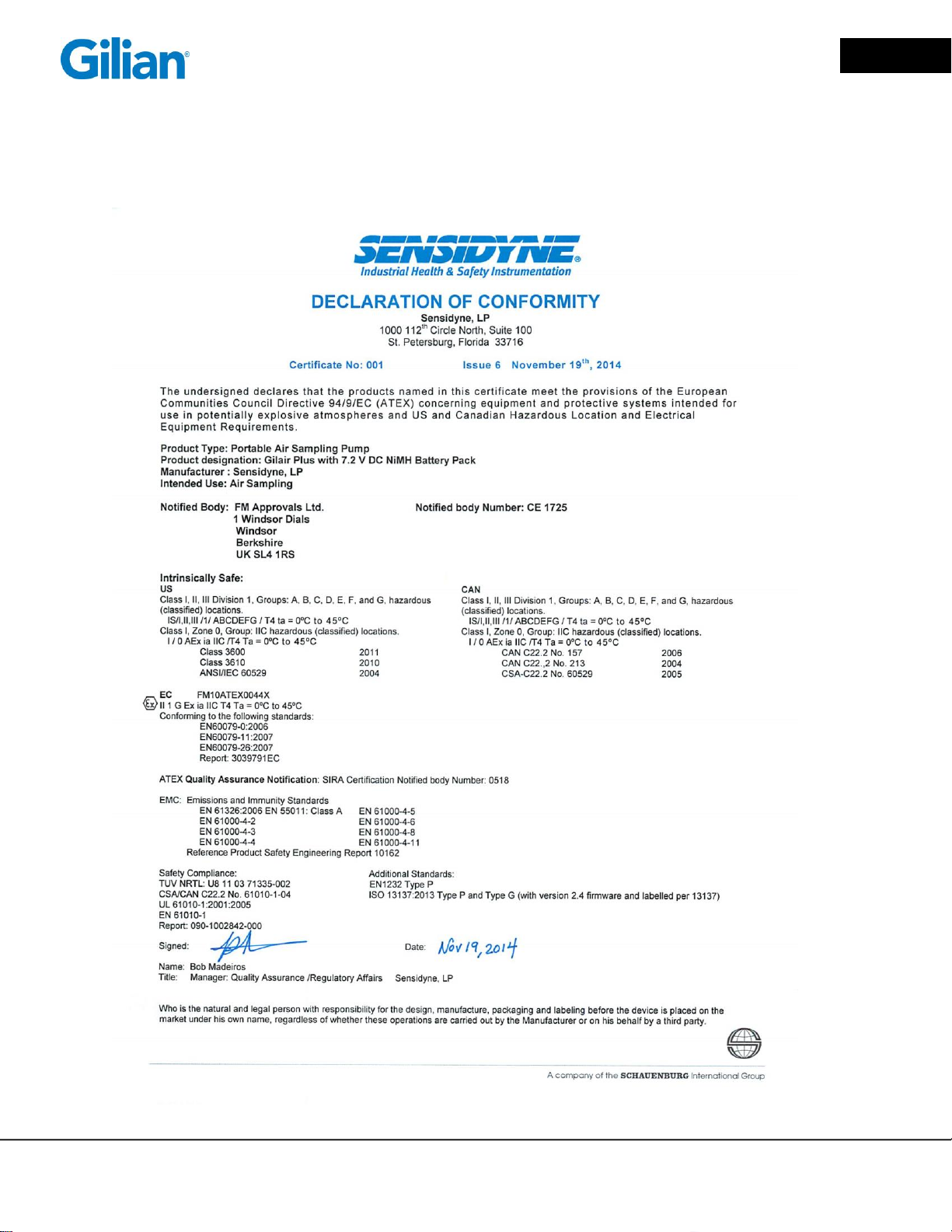
Certifications, Approvals and Compliances
Declaration of Conformity
Sensidyne Document No. 360-0132-01 (Rev T Software version 2.4.0) © 2015 Sensidyne, LP

Page 6
Gilian GilAir® Plus Air Sampling Pump – Operation Manual
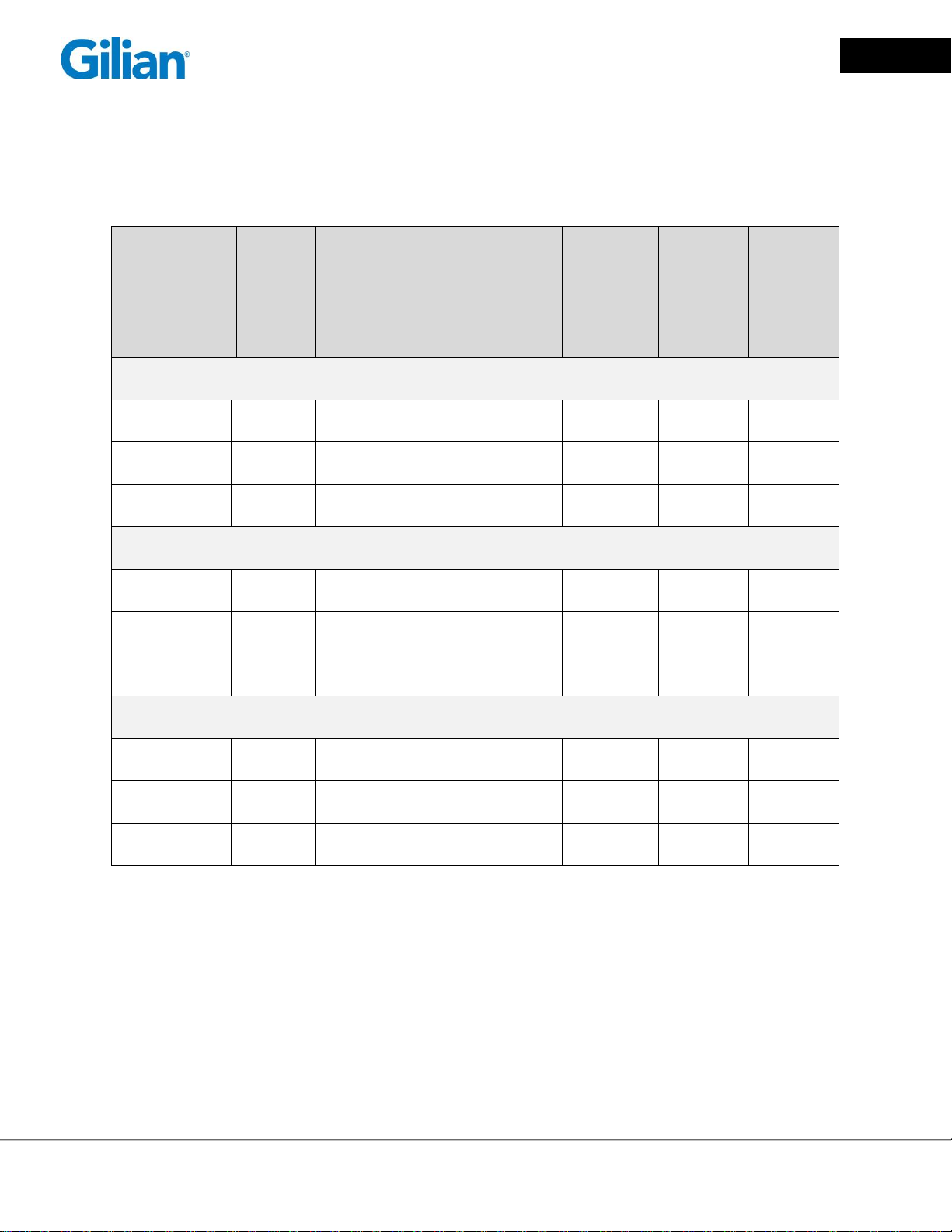
Pump
Model
Flow Rate
1 to 5100
cc/min
Constant
Flow &
Constant
Pressure
Battery
Options
NiMH,
Alkaline
& DC
Simple
Program
Functions
(Timer
Only)
Advanced
Program
Functions
Datalogging
& Transfer
to PC
Automatic
Calibration
Option
(SmartCal)
Standard
Temp &
Pressure
Data
Basic
*
Datalog
STP
SECTION TWO: Introduction
2.1. Product Description
The GilAir Plus is an advanced personal air sampling pump system available in three
models: a basic model, a datalogging pump (DL) model, and standard temperature and
pressure (STP) model. The STP model corrects the display flow rate and air volume to
standard conditions of temperature and pressure. The STP model can also correct
pump flow rate to keep flow constant with changes in barometric pressure and ambient
temperature.
All models offer constant flow modes and constant pressure control modes. The
Constant Flow Mode holds the set flow constant against changing backpressure within
5% or 3 cc/min whichever is larger. The Constant Pressure Mode holds the pressure
constant when taking samples using constant resistance sampling trains. The constant
pressure (multi-flow) mode allows the air stream to be split into two or more separate
samples so that multiple samples can run at the same time. (See Appendix D for
information on the dual port manifold) Furthermore, all models offer a built-in low
constant flow mode, such that flow rates are attainable from 20 cc/min to 5100 cc/min
without the addition of an external low flow adapter. Operation down to 1 cc/min is
possible in the constant pressure mode. Additionally, all models offer start-stop
programmability. A matrix chart for the available pump models are shown above.
*Note: SmartCalSM Automatic calibration is only available on all pump models when
used with a communications-enabled Dock. The standard Dock that comes with the
basic pump does not have communication capability and will not support the SmartCal
feature.
© 2015 Sensidyne, LP Sensidyne Document No. 360-0132-01 (Rev T, Software version 2.4.0)
Page 7
Gilian GilAir® Plus Air Sampling Pump – Operation Manual
Kit Type
GilAir
Plus
Pump
Dock
Carrying
Case
Filter
Cassette
Holder
Charcoal
Tube
Holder
CD with
Software
and
Manual /
Printed
Manual
Single Starter Kit
Basic
1
Single-Station
Standard
No 1 1
1/1
Datalog (DL)
1
Single-Station with
Communication
No 1 1
1/1
STP
1
Single-Station with
Communication
No 1 1
1/1
Three-Pack Starter Kit
Basic
3
Three-Station
Standard
Yes 3 3
1/1
Datalog (DL)
3
Three-Station with
Communication
Yes 3 3
1/1
STP
3
Three-Station with
Communication
Yes 3 3
1/1
Five-Pack Starter Kit
Basic
5
Five-Station
Standard
Yes 5 5
1/1
Datalog (DL)
5
Five-Station with
Communication
Yes 5 5
1/1
STP
5
Five-Station with
Communication
Yes 5 5
1/1
2.2. Pump Kit Descriptions
Kits are available in one, three and five pump configurations, with power cords in US,
Euro and UK versions. A matrix chart for the available kits are provided below.
See Appendix F for part numbers for pumps, kits and accessories.
Sensidyne Document No. 360-0132-01 (Rev T Software version 2.4.0) © 2015 Sensidyne, LP

Page 8
Gilian GilAir® Plus Air Sampling Pump – Operation Manual
SECTION THREE: Set-Up
3.1. Preparation
The package includes the pump, Dock, Dock power supply, and a line cord. The Dock
serves as the charging base for all models and the communications Dock for the
datalogging and STP models.
Plug the power supply into the Dock and the AC power cord into the power supply.
Connect the AC power cord to mains supply. The supply can accept 100-240 VAC at
50 or 60 Hz.
The pump arrives fully assembled.
IMPORTANT
Before proceeding, you MUST charge the battery to full capacity prior to using the
pump. To charge the pump, place it onto the charging base. The pump’s belt clip
secures the pump in place. Connection is made via contact points on both sides of the
belt clip.
Allow up to five hours for a complete charge. A red LED on the pump indicates
charging in progress; a green LED indicates charged and ready for use. The green
LED will flash during top off charge and is on constantly while on trickle charge. For
more information on charging, see Appendix H.
3.2. Pump Start Up
3.2.1. Power Up
Power pump on by pressing and holding down (about 2 seconds) the button
until the pump turns on.
3.2.2. Startup sequence
As the pump starts it goes through a number of phases that check for correct pump
operation and special situations at startup.
Startup Phases:
1. Power verification: Before starting the voltage from the power source
(battery or DC) must be more than 6.3v. A display screen notifies the user
when the voltage is low and displays the voltage. This typically occurs when
a deeply discharged battery is placed on the Dock during the initial charge
phase to bring the battery to adequate voltage for powering the system.
© 2015 Sensidyne, LP Sensidyne Document No. 360-0132-01 (Rev T, Software version 2.4.0)

Page 9
Gilian GilAir® Plus Air Sampling Pump – Operation Manual
Datalog Index:
Datalog is checked for validity and the index is created.
The number displayed is the number of events in the
datalog
Calibration:
The system calibrations are checked for validity.
Point Cal:
Flow calibrations are checked for validity.
System setup:
The block of memory containing the user set parameters is
checked for validity.
Programs:
The user program area is checked for validity.
2. Dock position determination: When starting up on a Dock, the system
pauses briefly to let the Dock provide the Dock position for use with the PC
App. If no position is available after 45 seconds, a message appears asking
the user to reseat the Dock.
3. Serial number display: The next display shows the product type (Basic,
Datalog or STP), the serial number and the software revision for about 5
seconds.
4. System initialization: During system initialization the memory is read and
checked for validity in the following sections.
5. Date Check/Set: If the current system date and time is earlier than the last
date/time stored, this message appears to remind that the date should be
reset.
3.2.3. Power Source Check
When the pump is charging on the Dock and the Dock status is being displayed, the
charge status reported from the Dock is compared to the type of battery that is
installed on the pump. If there is a discrepancy, the pump will signal the user by
flashing the backlight and show a message asking for the pump to be removed.
This is done to prevent the Dock from charging the battery in an inappropriate
manner, which could result in the battery not being charged or being overcharged.
3.2.4. Power Down
Turn power off from any display when the pump is not running by pressing and
holding down the button. After approximately two seconds a power down
display will appear and a five second shutdown sequence will start. If the button is
released before the shutdown sequence is complete the power will not switch off. At
the termination of the shutdown sequence, power is off.
Note: Power cannot be shut down if a sample or program is running.
Sensidyne Document No. 360-0132-01 (Rev T Software version 2.4.0) © 2015 Sensidyne, LP

Page 10
Gilian GilAir® Plus Air Sampling Pump – Operation Manual
3.3. Setting the Flow Rate
On the main menu, use the button to move the cursor to Flow Set. Adjust the flow
rate to the desired value using the and buttons. Press and release the
button to confirm the change.
3.4. Power Options
The GilAir Plus comes standard with a rechargeable nickel metal hydride (NiMH) battery
pack. The unit is charged through the Dock that is included with all starter kits.
An optional alkaline battery pack (P/N 783-0013-01-R) is available that allows the use of
over-the-counter AA batteries.
A third option, the DC power pack (783-0014-01-R) allows extended run times with the
pump on the Dock for pumps with firmware versions up to revision 2.4. Pumps that
have firmware version 2.4 or higher are supplied version 3.5 Docks that support running
for extended periods of time while charging on the Dock without the need for the
separate DC power pack.
Note: Do not attempt PC communications with the Dock, when running a sample,
calibrating, or editing pump settings.
Warning: Alkaline batteries, lithium batteries and the DC power pack should only
be used in non-hazardous areas. Intrinsic safety certifications are only valid
when using the rechargeable NiMH battery pack.
© 2015 Sensidyne, LP Sensidyne Document No. 360-0132-01 (Rev T, Software version 2.4.0)

Page 11
Gilian GilAir® Plus Air Sampling Pump – Operation Manual
SECTION FOUR: General Operation
4.1. Overview
The GilAir Plus has the capability of generating and controlling flow over the range of 20
cc/min to 5100 cc/min in two flow ranges, 20-445 cc/min, and 450-5100 cc/min, that are
selectable using a 2 mm or 5/64 inch hex key (provided with the pump). The actual flow
is measured and controlled by the pump’s internal processor. Flow control is provided
directly in the constant flow mode. Pressure control is provided in the constant pressure
control mode, which controls flow indirectly. During a sampling event the flow rate is
displayed in the constant flow mode and backpressure is displayed in the constant
pressure mode. Pump flow is not displayed in the constant pressure mode. The STP
models measure the ambient temperature and pressure and can correct sample
volumes and flows to Standard conditions. Standard temperature and pressure can be
set to desired values. In addition, if enabled, the flow rate can be compensated for
changes in temperature and pressure from the calibration point, holding the calibration
value against altitude induced variability. (Appendix C)
4.2. Connections
Sample media is connected to the inlet port using ¼ inch ID tubing. Adapters that
cause high pressure drop or using smaller diameter tubing may affect the sample flow.
Minimize pressure drop in tubing and fittings and avoid any condition that will exceed
the pump backpressure specifications (see Appendix E). The input port is part of the
input manifold that provides input connection, output connection and contains a filter
that protects the pump from contamination by particulates if operated without an
effective sampling filter. This filter is user replaceable and should be replaced if
discolored, clogged or obstructed in any way.
An output adapter accommodates filling sample containers such as Tedlar or Kynar
sampling bags. Connect the bag fill adapter as shown below. The connection is sealed
with a precision taper and should be inserted only finger tight. The knurled handle will
not seat flush to the surface of the pump and should not be forced. The sample bag
attaches with ¼ inch ID tubing. If the pressure in the bag increases, such as when it is
completely filled, the pressure increase will be shown as increased pump backpressure
and will terminate the event if the backpressure specification is exceeded.
Sensidyne Document No. 360-0132-01 (Rev T Software version 2.4.0) © 2015 Sensidyne, LP
Page 12
Gilian GilAir® Plus Air Sampling Pump – Operation Manual
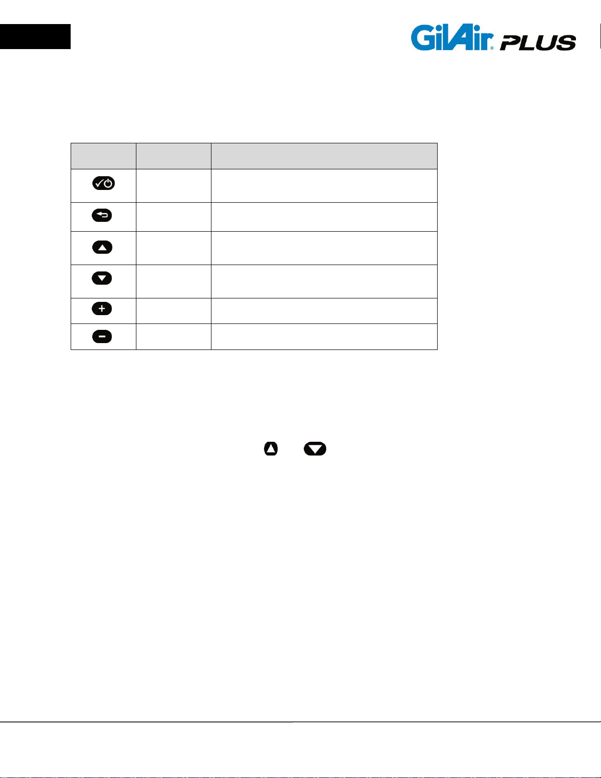
Symbol
Name
Function
Power/Enter
Powers the unit up or down, and enters a
menu or confirms a parameter change
Escape
Exits a menu
Up Arrow
Select display screen options or move
cursor up menu
Down Arrow
Select display screen options or move
cursor down menu
Increase
Adjusts a parameter to higher values
Decrease
Adjusts a parameter to lower values
4.3. Navigation
The GilAir Plus pump uses an intuitive six-button keypad for menu navigation and pump
operation. The buttons and their functions are summarized in the table below.
4.4. Menus
The operation of the pump is controlled by entering the menu system and selecting the
menu item that performs the desired function. The menu has submenus that allow
control of related functions. A quick reference menu outline appears in Appendix A.
When the menu is not displayed, the and buttons select among the display
screen options. The display screens are automatically selected by the pump whenever
the mode of operation is changed (example: when an event is started or a fault occurs).
The display screens include the Idle display, the Constant Flow control operating
display, the Constant Pressure control operating display, the Fault display, Program
Status display and STP Display (STP Models only). A description of the data
displayed on each menu screen is contained in the Displays section (Section 4.5. ) of
this manual.
Sampling events: The GilAir Plus accumulates sample data on events. An event is a
sample run. The data for each sample event is stored as the event progresses so that
no data loss is possible. When a sample is started, the event data is cleared to begin
the new event. As the pump samples, the flow is controlled at the event flow rate or
pressure depending on the selected control mode. The event data (time, flow, volume,
backpressure and other information) is stored into nonvolatile memory.
If the pump is paused the event is not terminated. When the event continues, volume
and time accumulation continue in the same event. If the event is stopped, the run data
is available for review (Section 6.10. ) and in the idle screen until another event is
started. The data from the last 16 events is available in the data review menu.
© 2015 Sensidyne, LP Sensidyne Document No. 360-0132-01 (Rev T, Software version 2.4.0)
Page 13
Gilian GilAir® Plus Air Sampling Pump – Operation Manual
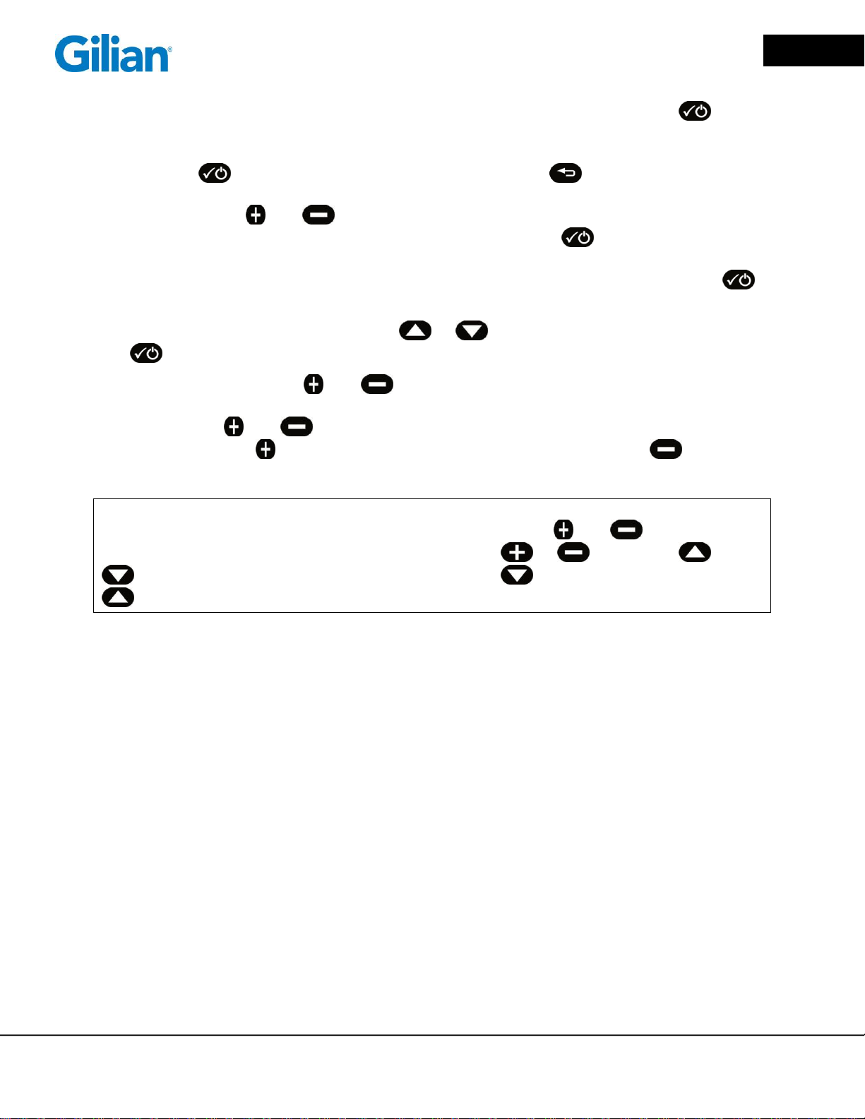
General operation of the menu system: Access the menu by pressing the
button. The menu is displayed in a vertical column. Some menu items have a ► sign
after the menu item and lead to submenus. When the selected menu has the ►,
pressing the button enters the submenu. Pressing the button exits the
submenu and returns to the higher level menu. If a parameter is displayed at the right
end of the line, the and buttons may be used to adjust the parameter up and
down. If a parameter is changed it will be retained only if the button is pressed to
confirm the change. If a parameter has been changed, an ▲ symbol (for an increase in
the parameter), or a ▼ symbol (signifying a decrease) is displayed to alert that the
button is required to confirm the change.
If the menu selection is altered with the or buttons without confirmation with
the button, the parameter will revert to its original value.
If the value is numeric, the and buttons alter the numeric value. If the
parameter is a selection, the buttons will select each option in sequence. The option
may require the and buttons to select. For instance, the “enable” selection is
always made by the button and the disable option is selected with the button.
NOTE: Several parameters have numeric values, allowing the user to scroll through the
entire range by simply pressing and holding down either the and buttons. In
addition to this feature after pressing and holding the or button, the and
buttons will accelerate the rate of scrolling. The button moderately and the
button quickly accelerates the rate.
Sensidyne Document No. 360-0132-01 (Rev T Software version 2.4.0) © 2015 Sensidyne, LP
Page 14
Gilian GilAir® Plus Air Sampling Pump – Operation Manual
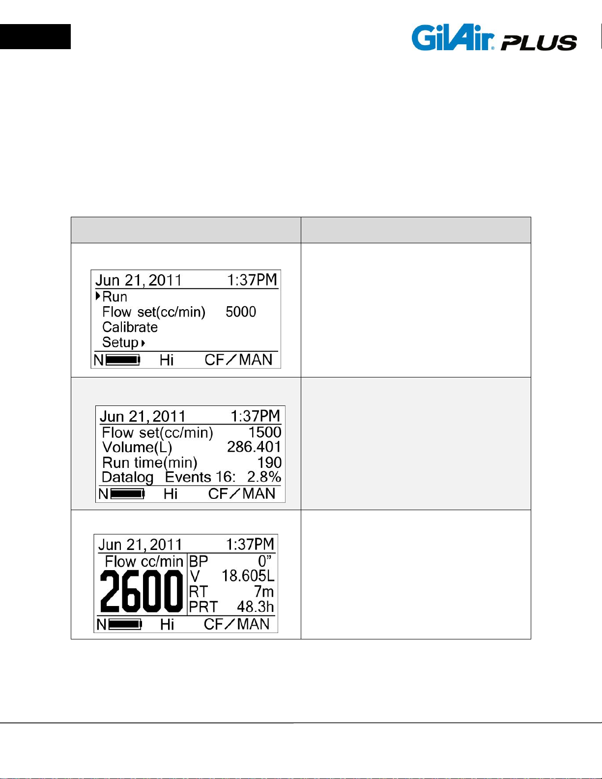
Displays
Description
Menu Display
The main menu allows all of the
parameters of the operation of the
GilAir Plus to be set, by scrolling to the
appropriate menu item (Section 4.3. )
Idle
Shown when the pump is not conducting
an event or in the main menu, Idle
displays Flow Set Point, Total Sample
Volume, Run Time and the number of
events stored and the percentage of the
datalog memory used.
Constant Flow
Displays Actual Flow rate (cc/min),
Backpressure BP (inches water, mmHg,
KPa or mbar), Total Sample Volume V
(Liters), Run Time RT (minutes) and
Projected Run Time PRT (hours), based
on battery charge status and
backpressure.
4.5. Displays
The display screens include the Menu display, Idle display, Constant Flow control
operating display, Constant Pressure control operating display, Fault display, and the
Program Status display. All displays include; the top status line displaying the Date,
Time, and lock status; bottom status line displays the Battery type and charge status,
Operating range (Hi or Lo), Control Mode (CF, CPL or CPH), and Run Mode (Manual,
Timed, or Program).
© 2015 Sensidyne, LP Sensidyne Document No. 360-0132-01 (Rev T, Software version 2.4.0)
Page 15
Gilian GilAir® Plus Air Sampling Pump – Operation Manual
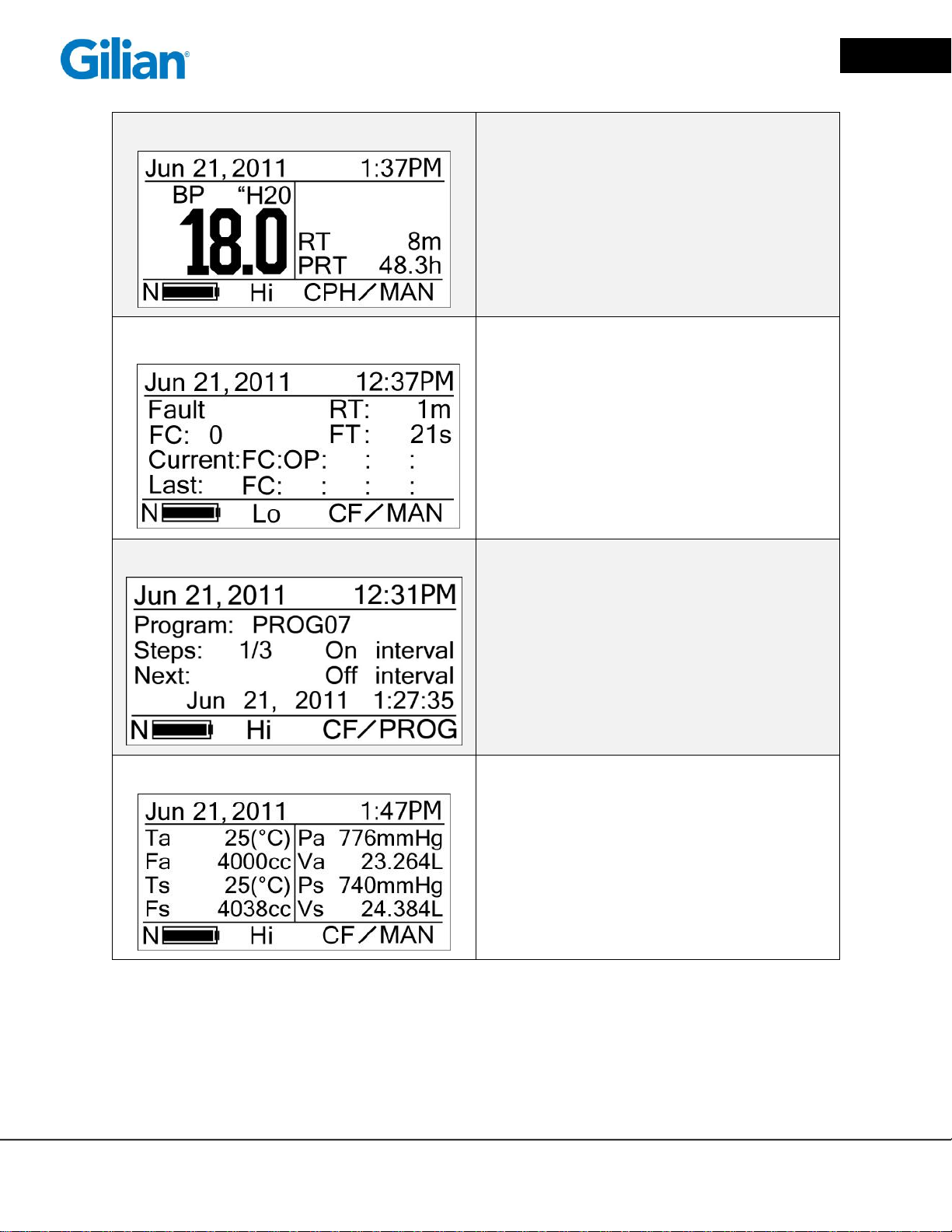
Constant Pressure
Displays Backpressure BP (inches water,
mmHg, KPa, mbar), Run Time RT
(minutes) and Projected Run Time PRT
(hours) based on battery charge status
and backpressure.
Fault'
Displays Run Time RT (min), Fault Count
FC, Fault Run Time FT (sec), Current
Fault(s) and Last Fault(s) when a fault
condition is detected or when the pump
has stopped due to a fault condition.
Program Status
Displays the status of a programmed run.
Number of steps in the total program and
the current and next step are shown. In
the current step the progress of the step
is shown.
STP
In the STP model pump, this screen
shows ambient temperature and pressure
averages from the active or previous
event and the standard values. Flow and
Volume are shown at ambient and
standard conditions.
The LCD display can be switched between several information screens through the
keypad. The pump will automatically switch to the appropriate display when certain
menu items are selected or the status of the pump changes.
Sensidyne Document No. 360-0132-01 (Rev T Software version 2.4.0) © 2015 Sensidyne, LP

Page 16
Gilian GilAir® Plus Air Sampling Pump – Operation Manual
4.5.1. Display Details
1. Date and time: Displayed in selectable format mm/dd/yy or dd/mm/yy
2. Battery icon: The NiMH battery pack is identified by an "N" to the left of the
icon, the AA replaceable pack is identified by an "A". When using a NiMH
or AA battery pack the charge state of the battery is shown. If the pump is
using a DC power pack on the Dock, "DC" is shown. Charge status is
approximate and depends on many factors including age, number of charge
cycles, temperature and recent charge or discharge history.
3. Flow range indicator: Displays "Hi", "Lo" or "Err" at all times. This indicator
shows the setting of the flow control valve, which determines high range or
low range operation of the pump. When the indicator shows "Err", the valve
is between positions and must be moved to the correct detent position to
operate the pump.
4. Control mode: Displays the event control mode of the pump, either constant
flow (CF) or constant pressure (CPH or CPL). In constant flow mode, the
pump controls the flow rate regardless of changes in the filter load
(backpressure). In constant pressure, the pump controls the inlet pressure,
regardless of the flow. The constant pressure modes, CPH and CPL, allow
the user to select the range of expected flow for optimum control.
5. Run mode: Displays the status of the Run mode, which indicates how the
pump’s sampling schedule is set. There are five modes; manual, the
operator turns the pump on and off; timed, the pump turns on at a preset
time and off at a specified number of minutes later; Vol, the pump turns on
at a specified time and collects a specified volume; RT, the pump turns on
at a specified time and runs for a specified number of minutes of run time,
and program, indicated by the name of the program, operating under the
timing control of a user defined program which specifies on and off times
and durations.
4.5.2. Menu Details
1. Menu items: See the Menu Outline in Appendix A for an outline of the pump
menu structure.
4.5.3. Idle Display Details
Idle Display: The idle display is visible when the pump is turned on and
whenever the pump is not in the menu or a sample event.
1. Flow set (cc/min): The flow rate, always shown in cc/min at ambient
conditions.
© 2015 Sensidyne, LP Sensidyne Document No. 360-0132-01 (Rev T, Software version 2.4.0)

Page 17
Gilian GilAir® Plus Air Sampling Pump – Operation Manual
2. Volume (L) - Sample volume: The total volume of the sample, always
shown in liters, at ambient conditions.
3. Run time (min) – Sample time in minutes.
4. Datalog Events: Displays the number of events recorded, and the
percentage of the storage area used.
4.5.4. Constant Flow Run Display Details
1. Flow cc/min: The flow rate, always shown in cc/min at ambient conditions.
2. BP - Back Pressure: The backpressure measured at the input to the pump
after the manifold and protective filter. The units of the backpressure can be
selected by the operator as inches of water, millimeters of mercury,
kilopascals or millibars.
3. V - Sample volume: The total volume of the sample, always shown in liters,
at ambient conditions.
4. RT - Run Time: Total pump ON time. Does not include Sensor calibrations,
pauses or scheduled off time in programs.
5. PRT - Projected Run Time: The projected run time is an estimate of the
remaining run time in hours, based on the current estimated battery capacity
and the current drain on the pump, which is dependent on flow rate,
backpressure and temperature.
4.5.5. Constant Pressure Display Details
1. BP - Back Pressure: The backpressure measured at the input to the pump
after the manifold and protective filter. The units of the backpressure can be
selected by the operator as inches of water, millimeters of mercury, millibars
or kilopascals.
2. RT - Run Time: Total pump ON time. Does not include Sensor calibrations,
pauses or scheduled off time in programs.
3. PRT - Projected Run Time: The projected run time is an estimate of the
remaining run time in hours, based on the current estimated battery capacity
and the current drain on the pump, which is dependent on flow rate,
backpressure and temperature.
Sensidyne Document No. 360-0132-01 (Rev T Software version 2.4.0) © 2015 Sensidyne, LP

Page 18
Gilian GilAir® Plus Air Sampling Pump – Operation Manual
4.5.6. Fault Display Details
1. RT - Run Time: Total pump ON time. Does not include Sensor calibrations,
pauses or scheduled off time in programs.
2. FC - Fault Count: Total number of faults that have resulted in suspension of
sampling. When the count reaches 10, the pump will cease retrying and
terminate the event.
3. FT - Fault Time: Total time, in seconds, the pump has run while being in a
fault status.
4. Current: Active fault display field of fault indicators, "None" is displayed
unless a fault is active. The faults that may be displayed are FC (flow control
out of range), PC (pressure control out of range), BP (Backpressure over
allowable limit), OP (Backpressure out of allowed range, causing
emergency stop), RV (recirculation valve incorrectly set for flow rate), and
LB (low battery).
5. Last: Previous fault condition, same format as Current fault.
4.5.7. Program Display
1. Program: Program name of selected program.
2. Steps: Number of active steps /Total number of steps Type of the active
step.
3. Next: Next step function.
4. Date and time of next step start.
4.5.8. STP Display
1. Ta: Average ambient temperature during active or last event
2. Pa: Average measured barometric pressure during active or last event
3. Fa: Ambient conditions flow rate
4. Va: Ambient conditions sample volume
5. Ts: Standard conditions temperature
6. Ps: Standard barometric pressure
7. Fs: Standard conditions flow rate
© 2015 Sensidyne, LP Sensidyne Document No. 360-0132-01 (Rev T, Software version 2.4.0)

Page 19
Gilian GilAir® Plus Air Sampling Pump – Operation Manual
8. Vs: Standard conditions sample volume
4.5.9. Barometric Compensation Display
1. Pa: Ambient barometric pressure
2. Pc: Calibration barometric pressure
3. Ta: Ambient temperature
4. Tc: Calibration ambient temperature
5. Correction factor: Adjustment to flow setpoint
Sensidyne Document No. 360-0132-01 (Rev T Software version 2.4.0) © 2015 Sensidyne, LP

Page 20
Gilian GilAir® Plus Air Sampling Pump – Operation Manual
4.6. Sensor Calibration
The GilAir Plus pump has a built in automatic sensor calibration feature which allows
the pump to maintain an accurate stable flow rate by intermittently calibrating the
pump’s flow sensor to establish the zero flow point. This routine occurs before starting,
when the internal temperature of the pump changes more than 3 degrees C, or
whenever one hour has elapsed since the last sensor calibration, depending on the
Sensor option setting (Section 5.12.3. ). The calibration takes approximately 20
seconds during which time the pump stops running. Sample time and volume are not
counted during the sensor calibration routine as the pump automatically accommodates
this brief stoppage in the accumulation of sample results. The message "Sensor
Calibration" displays during this process. The sensor calibrations eliminate the effect of
sensor drift on flow rate stability. If the sensor calibrations are reduced or eliminated
(Section 5.12.3. ) flow stability may be affected.
4.7. Run Mode
4.7.1. Run Mode Descriptions
Selecting Run begins a sampling event. The previous event data is cleared. Before
selecting Run, the control mode, constant flow or constant pressure should have the
proper setting and the flow rate or control pressure should be at the desired set
point. If Manual Run Mode is active, the pump starts in the selected control mode at
the set point. If the Timed Run Mode is selected, the pump waits for the start time
and then starts and runs until the start time plus the specified duration. If the Vol
Run Mode is selected, the pump waits for the start time and then starts and runs
until the specified volume has been collected. If the RT Run Mode is selected, the
pump waits for the start time and then starts and runs until the run time has elapsed;
this does not count pauses, sensor calibration intervals and fault stop times. If the
Program Run Mode is selected, the program starts and controls sampling until the
program completes. When running in the high flow mode, a “Connect Media”
message will pop up on the screen periodically if the pump does not see the
expected backpressure caused by a sample train.
Note: The pump is designed to operate with a minimum backpressure of 2”
H2O while in the high flow mode. Operating the pump in high flow mode
without any collection media attached or at a backpressure of less than 2”
H2O will result in inaccurate performance.
When the Run menu item is selected, readiness to start the event is evaluated. If
the pump is using battery power, the battery status is checked. If the battery has
less than about 5% of remaining charge, the event will not start. If the battery has
less than 90% charge, a message box will appear to warn that the battery is not fully
charged.
© 2015 Sensidyne, LP Sensidyne Document No. 360-0132-01 (Rev T, Software version 2.4.0)
Page 21
Gilian GilAir® Plus Air Sampling Pump – Operation Manual
The recirculation valve is checked for proper position. If it is incorrectly positioned, a
popup message will alert the user. If the valve is moved to the correct position, the
event start evaluation will continue. If the ESC button is pressed, starting the event
will be abandoned and control will return to the menu.
The Event log is checked for available space. If space is not available, a message
will warn the user. If the ESC button is pressed, starting the event will be
abandoned and control will return to the menu to allow the data to be recorded or
downloaded before continuing. If ENTER is pressed, the pump will enter the clear
datalog dialog and allow the datalog to be cleared. If the datalog is not cleared the
event cannot begin. If the datalog is cleared, the event will start.
If the Event ID option is enabled, the user will be prompted to enter an Event ID,
which will be stored with the event data for later review or download.
If the Pre/Post Cal option is enabled, a Pre-Cal flow calibration will start. If the ESC
key is used to exit the Pre-Cal flow calibration, the event will start without adjusting
the flow rate or recording a Pre Pre-Cal reading. The preset SmartCal device will be
used if the pump is on the Dock, otherwise a manual calibration will be performed.
The Stop menu can be accessed by the button during Run to pause or stop the
event. If Pause is activated the pump stops with flow, timing, and total volume
accurately maintained. The menu changes to allow continuation of the event. The
Stop menu item terminates the sample event. The keypad can be locked to avoid
event modification as described in the next sections.
4.7.2. Locking the Keypad
To lock the keypad:
Press and hold down simultaneously the and buttons. A lock symbol will
appear in the top status line. Release the buttons and the pump will be locked. After
locking the pump it will only respond using the and buttons to access the
Idle, Fault, Program and Standard Conditions status screens. Warning: If a
password is in place to restrict access to the pump, it will have to be entered to
unlock the pump. Be certain that you know the password before you lock the pump.
4.7.3. Unlocking the Keypad
To unlock the keypad:
Press and hold down simultaneously the and buttons. The lock symbol will
disappear from the top middle portion of the screen. Release the buttons, and the
pump will be unlocked.
Sensidyne Document No. 360-0132-01 (Rev T Software version 2.4.0) © 2015 Sensidyne, LP

Page 22
Gilian GilAir® Plus Air Sampling Pump – Operation Manual
IMPORTANT! – The above instructions apply only if no Password (Section 5.15. )
has been selected for the pump (the Password is set at the factory default value of
0, disabled). If a Password has been previously selected, after the user has
performed the instructions above, the keypad will prompt the user to enter the
Password, then press and release the button before the pump will unlock itself.
© 2015 Sensidyne, LP Sensidyne Document No. 360-0132-01 (Rev T, Software version 2.4.0)
 Loading...