

Page 1
GILDERFLUKE & CO .• 205 SOUTH FLOWER STREET • BURBANK , CALIFORNIA 91502 • 818/840-9484 • 800/776-5972 • FAX 818/840-9485
E
AST COAST /FLORIDA O FFICE • 7041 GRAND NATIONAL DRIVE • SUITE 128d • ORLANDO , FL. 32819 • 407/354-5954 • FAX 407/354-5955
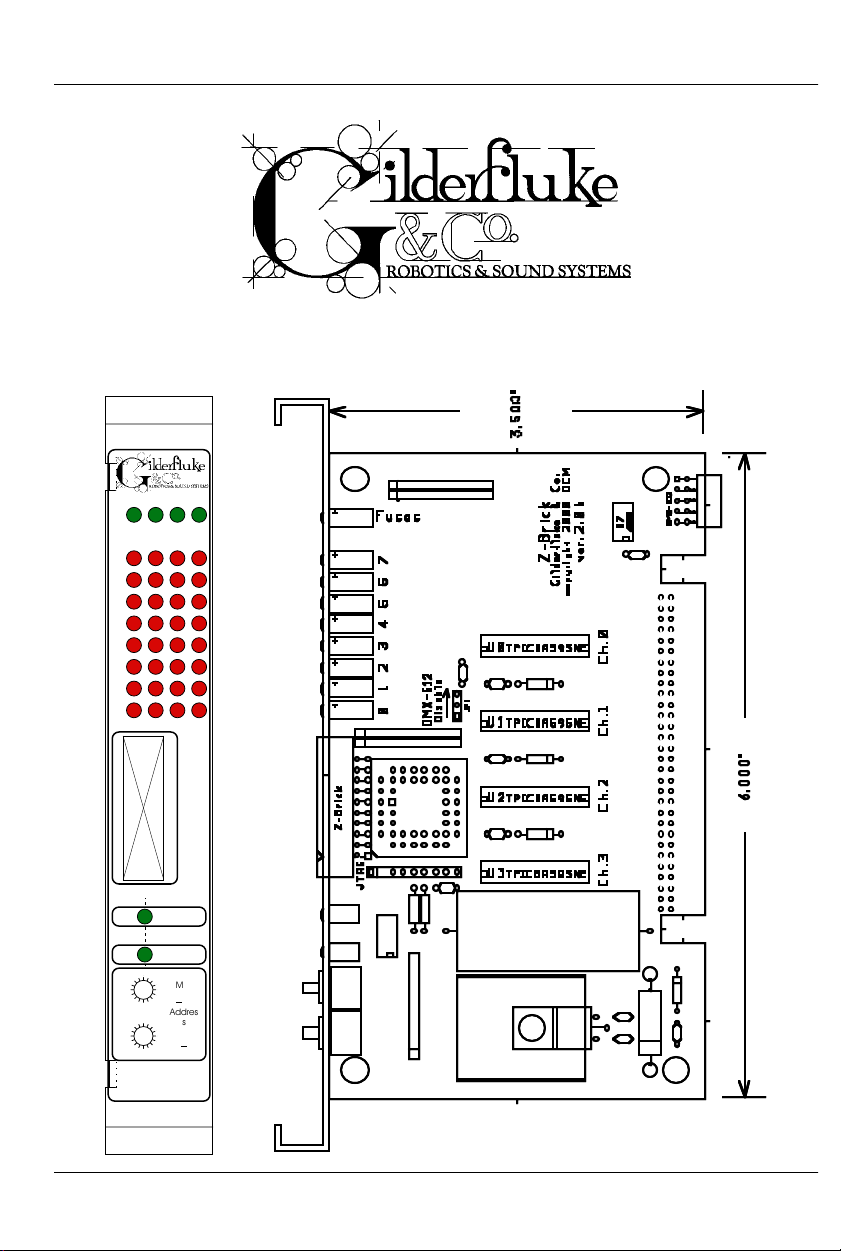
Z-Brick
Printed April 25, 2002
0123
Fuse
s
Output
s
7
6
5
4
3
2
1
0
DMX Rec'd
0
1
F
26AE
3
D
5
B
97
8
0
1
F
26AE
3
D
5
B
97
8
Z-Brick
4C
4C
Z-Buss
Updat
e
MSB
x0h)
(
Addres
(0
s
LSB
xh)
i of iii
Page 2

GILDERFLUKE & CO .• 205 SOUTH FLOWER STREET • BURBANK , CALIFORNIA 91502 • 818/840-9484 • 800/776-5972 • FAX 818/840-9485
E
AST COAST /FLORIDA O FFICE • 7041 GRAND NATIONAL DRIVE • SUITE 128d • ORLANDO , FL. 32819 • 407/354-5954 • FAX 407/354-5955
Safety Disclaimer: Any electronic or mechanical
system has the potential to fail. Certain applications using Gilderfluke & Company equipment may
involve potential risks of death, personal injury or
severe property or environmental damage
(“Critical Application”).
Gilderfluke & Company equipment is not designed, intended, authorized or warranted to be
suitable in life support applications, devices or
systems or other critical applications. Inclusion of
Gilderfluke & Company products in such applications is understood to be fully at the risk of the customer. In order to minimize risks associated with
the customer's applications, adequate design and
operating safeguards should be provided by the
customer to minimize inherent or procedural hazards.
Gilderfluke & Company assumes no liability for
applications assistance, customer produced design, software performance, or infringement of
patents or copyrights. Nor does Gilderfluke &
Company warrant or represent that any license, either express or implied, is granted under any
patent right, copyright, mask work right, or other intellectual property right of Gilderfluke & Company
covering or relating to any combination, machine,
or process in which Gilderfluke & Company products or services might be or are used.
ii of iii
Page 3

GILDERFLUKE & CO .• 205 SOUTH FLOWER STREET • BURBANK , CALIFORNIA 91502 • 818/840-9484 • 800/776-5972 • FAX 818/840-9485
E
AST COAST /FLORIDA O FFICE • 7041 GRAND NATIONAL DRIVE • SUITE 128d • ORLANDO , FL. 32819 • 407/354-5954 • FAX 407/354-5955
Overview .............................................................. 1
Z-Brick with DMX-512 input ..................................... 1
Z-Brick as a Digital Output Expander ....................... 1
On the Front of the Z-Brick ................................... 4
Output LEDs ........................................................................... 4
Fuses LEDs ............................................................................. 4
Update LED ............................................................................ 4
DMX-512 LED ......................................................................... 4
Address Switches ................................................................... 4
Z-Buss .................................................................................... 4
On the Back of the Z-Brick ................................... 6
J-6 cable ............................................................................... 7
Output Capacity ................................................................... 8
DMX-512 Data In/Out ............................................................ 9
Edge Connector .................................................................. 10
HEXadecimal to Decimal to Percentage ......... 12
iii of iii
Page 4

GILDERFLUKE & CO .• 205 SOUTH FLOWER STREET • BURBANK , CALIFORNIA 91502 • 818/840-9484 • 800/776-5972 • FAX 818/840-9485
E
AST COAST /FLORIDA O FFICE • 7041 GRAND NATIONAL DRIVE • SUITE 128d • ORLANDO , FL. 32819 • 407/354-5954 • FAX 407/354-5955
A note about this manual:
This manual covers the specifics of the ZBrick. To program the Z-Brick you will need to
also need the PC•MACs manual sections that
cover the PC•MACs software.
Gilderfluke Show Control Equipment is
sometimes programmed in ‘Software-only’ or
‘Hardwareless Realtime’ mode. Refer to the
‘Quick Start’ sections of the PC•MACs manual if
you are unfamiliar with their use. If you are
using the PC•MACs MACs-SMP or MACs-USB for
programming your Z-Brick through the DMX512 input, please refer to the PC•MACs
‘Unlimited’ mode.
The full PC•MACs manual can be downloaded from our web site at:
http:/ /www.gilderfluke.com
iv of iv
Page 5

GILDERFLUKE & CO .• 205 SOUTH FLOWER STREET • BURBANK , CALIFORNIA 91502 • 818/840-9484 • 800/776-5972 • FAX 818/840-9485
E
AST COAST /FLORIDA O FFICE • 7041 GRAND NATIONAL DRIVE • SUITE 128d • ORLANDO , FL. 32819 • 407/354-5954 • FAX 407/354-5955
Overview:
The Z-Brick is an output card which has thirty-two digital outputs. It is designed to be used as an output card for use in a
PC•MACs system, or as a digital output expansion card for BRANAs, BR-EFBs, BR-SmartMedia, or any other Gilderfluke &
Company card which provides a Z-Buss or DMX-512 output.
Each Z-Brick adds another thirty-two digital outputs. Up to sixtyfour Z-Bricks can be used for a total of 2048 digital outputs.
The Z-Brick can be used in two different ways:
1) Z-Brick with DMX-512 input: In this mode the Z-Brick receives up to 256 channels of DMX-512 data transmitted
by a PC•MACs Animation Control System, or any other
source of DMX-512 data, and uses four channels of this
data to update its outputs. The Z-Brick can be addressed to use any DMX-512 address from 0 to 255. The
DMX-512 input allows the Z-Brick to be used as a permanent output device for a PC•MACs or other Animation or
Lighting Control System. DMX-512 reception can be disabled by moving the ‘DMX-512 Disable’ jumper to the
‘disabled’ position.
2) Z-Brick as a Digital Output Expander: BR-ANAs, BREFBs, BR-SmartMedia, and some other Gilderfluke &
Company cards don’t themselves have digital outputs.
One or more Z-Bricks can be attached to these cards via
the twenty position IDS ‘Z-Buss’ connection on their front
panels.
In either of the modes, the Z-Brick’s thirty-two outputs are addressed as four consecutive eight bit channels. This means that
each Z-Brick needs four eight bit channels worth of data. The two
HEXadecimal switches on the front of the Z-Brick are used to set
the address. The address is set using HEXadecimal numbers (a
chart which shows both numbering systems is at the rear of this
1 of 12
Page 6

GILDERFLUKE & CO .• 205 SOUTH FLOWER STREET • BURBANK , CALIFORNIA 91502 • 818/840-9484 • 800/776-5972 • FAX 818/840-9485
E
AST COAST /FLORIDA O FFICE • 7041 GRAND NATIONAL DRIVE • SUITE 128d • ORLANDO , FL. 32819 • 407/354-5954 • FAX 407/354-5955
and all Gilderfluke manuals). The upper switch is used to set the
upper hex nibble’s address. The lower switch is used to set the
lower hex nibble’s address.
As an example, a typical address for a Z-Brick is right after the
sixteen eight bit resolution analog outputs on a BR-ANA. If the BRANA outputs are addressed at address 0, then the last analog
channel is in address 15. This translates to 0Fh, so the first address which is available to the Z-Brick is 16 (decimal), or 10h. To
set this address on a Z-Brick, the upper address switch would be
set to ‘1’, and the lower switch set to ‘0’.
Another common address is right after sixteen analog outputs
of a BR-ANA which are set to twelve bits of resolution. These sixteen
twelve bit resolution outputs occupy twenty-four channels worth
of data. If they are addressed at address 0, then the last analog
channel is in address 23. This translates to 17h, so the first address which is available to the Z-Brick is 24 (decimal), or 18h. The
upper address switch needs to be set to ‘1’, and the lower switch
set to ‘8’.
The Z-Brick can be mounted in one 1” wide slot in any of our
Brick Card cages. The Z-Brick can be used in conjunction with
any selection of Smart Bricks, Smart Brick Brains, Electronic
FeedBack (EFB) Smart Bricks and Z-Bricks in the same card cage.
Card cages with one, two or sixteen slots are available. The card
cages provide all of the connections for power supply, control
signals and outputs that any Brick card will need. Several different styles of output connectors are available on the one and two
slot card cages. The sixteen slot card cage mounts in seven
inches (4U) of standard 19” rack space (4-1/2“ of space behind
the panel). In some applications you may need to mount a single Smart Brick. This can be done by mounting the Brick on
standoffs, and connecting to the card's edge connector with a
mating connector. We usually recommend a sixty position insulation displacement connector for this type of installation.
2 of 12
Page 7

GILDERFLUKE & CO .• 205 SOUTH FLOWER STREET • BURBANK , CALIFORNIA 91502 • 818/840-9484 • 800/776-5972 • FAX 818/840-9485
E
AST COAST /FLORIDA O FFICE • 7041 GRAND NATIONAL DRIVE • SUITE 128d • ORLANDO , FL. 32819 • 407/354-5954 • FAX 407/354-5955
Power requirements for each Z-Brick are 9 to 24 VDC. The actual current requirements are determined by the loads attached
to the unit. The Z-Brick itself draws about 200 ma. of current.
3 of 12
Page 8

GILDERFLUKE & CO .• 205 SOUTH FLOWER STREET • BURBANK , CALIFORNIA 91502 • 818/840-9484 • 800/776-5972 • FAX 818/840-9485
E
AST COAST /FLORIDA O FFICE • 7041 GRAND NATIONAL DRIVE • SUITE 128d • ORLANDO , FL. 32819 • 407/354-5954 • FAX 407/354-5955
On the Front of the Z-Brick:
A) Output LEDs: These thirty-two LEDs show the current status of the
thirty-two digital outputs. If a LED is lit, then that output is ‘ON’.
Because the outputs of a Z-Brick are ‘Open Collector, Switch To
Ground’, you can ground out any output pin, and the appropri-
ate LED will light. This can be useful when diagnosing output
wiring problems. If you are commanding ‘on’ an output and you
don’t see a LED, then the output is probably drawing too much
current and the output is ‘self protecting’. Disconnect the load
and see if the LED now lights. If it does, then it definitely is an
overload problem. If it does not, then try turning ‘on’ some of the
other outputs. if they light OK, then the output driver might be
damaged. If they do not, then verify your addressing and retest.
B) Fuse LEDs: The thirty-two outputs of the Z-Brick are divided into
four, eight bit ‘channels’. Each of these channels is fused for ap-
proximately one Amp of continuous current. These four LEDs light
to show if the four fuses are OK. If any are out, then a short circuit
(or too heavy of a load) is dragging the outputs down and caus-
ing the fuse to open. The fuses are actually ‘PTC fuses’, which act
more like circuit breakers. Once the overload is removed, they
reset.
C) Update LED: This LED will flash on each update from DMX-512 or
the Z-Buss. It shows you the the Z-Brick is receiving data OK.
D) DMX-512 LED: This LED will be lit when the Z-Brick is receiving
DMX-512 data. DMX-512 reception can be disabled by moving
the ‘DMX-512 Disable’ jumper to the ‘disabled’ position.
E) Address Switches: The address for the Z-Brick is set using
Hexadecimal numbers. The first digit of the Hexadecimal address
is set on the upper of the two switches. The second digit of the
hexadecimal address is set on the lower of the two switches. If
you are not sure how these translate from decimal numbers, a
chart at the end of every Gilderfluke & Company manual will
show you the equivalent numbers..
F) Z-Buss: This twenty pin IDS connector is used to connect one or
more Z-Bricks to the ONE card that is sourcing data. This ‘sourcing’
card can be a BR-ANA, BR-EFB, BR-SmartMedia, or any other
Gilderfluke & Co. card with an appropriate Z-Buss output. The BR-
ANA, BR-EFB, or BR-SmartMedia outputs data from the DMX-512 or
serial input or onboard Flash Memory to this connector. The
pinouts of this connector is as follows:
4 of 12
Page 9

GILDERFLUKE & CO .• 205 SOUTH FLOWER STREET • BURBANK , CALIFORNIA 91502 • 818/840-9484 • 800/776-5972 • FAX 818/840-9485
E
AST COAST /FLORIDA O FFICE • 7041 GRAND NATIONAL DRIVE • SUITE 128d • ORLANDO , FL. 32819 • 407/354-5954 • FAX 407/354-5955
IDS pin # SIGNAL
1 Data bit 0
2 Data bit 1
3 Data bit 2
4 Data bit 3
5 Data bit 4
6 Data bit 5
7 Data bit 6
8 Data bit 7
9 Address bit 0
10 Address bit 1
11 Address bit 2
12 Address bit 3
13 Address bit 4
14 Address bit 5
15 Address bit 6
16 Address bit 7
17 ground
18 ground
19 Strobe/
20 Reset/
When the address and data lines are valid, the rising edge of
the Strobe line will latch the data into the addressed outputs.
If the Z-Buss input is not going to be used, you should insert a
two position jumper between pins #17 and #19. This will tie down
any spurious outputs that might otherwise happen if the DMX-512
data is not present. The Z-Bricks ship from Gilderfluke & Co. with a
jumper in just this position.
5 of 12
Page 10

k
GILDERFLUKE & CO .• 205 SOUTH FLOWER STREET • BURBANK , CALIFORNIA 91502 • 818/840-9484 • 800/776-5972 • FAX 818/840-9485
E
AST COAST /FLORIDA O FFICE • 7041 GRAND NATIONAL DRIVE • SUITE 128d • ORLANDO , FL. 32819 • 407/354-5954 • FAX 407/354-5955
On the Back of the Z-Brick:
In all animation systems made by Gilderfluke & Company all digital output cabling is through what we call ‘J-6’ standard output cables. These are
forty wire cables which are made up of four identical eight bit wide ‘channels’. A J-6 cable is often split up into four individual channels. As each
channel also includes a common power supply and ground wire, each ‘1/4
J-6’ cable is made up of ten wires, and can be used to control eight individual ‘digital’ (off/on) devices, or one eight bit wide ‘analog’ device.
All Gilderfluke & Co. digital outputs are open collector switches to
ground, and all inputs are opto isolated. Flyback diodes are included in the
outputs for driving inductive loads:
fuse
flybac
supply supply
diode
typical output
typical input
To simplify wiring to any MACs animation system, the connectors
used on the J-6 cables are what are called ‘insulation displacement connectors’. These simply snap on to an entire cable, automatically ‘displacing’
the wire insulation and making contact with the wires within. This means
that an entire 40 wire cable can be terminated in seconds. All connectors
are polarized, to keep them from being plugged in backwards. Although
there are tools made specifically for installing these connectors, the tool we
find works best is a small bench vise.
6 of 12
Page 11

d
d
d
d
d
d
-
-
-
GILDERFLUKE & CO .• 205 SOUTH FLOWER STREET • BURBANK , CALIFORNIA 91502 • 818/840-9484 • 800/776-5972 • FAX 818/840-9485
E
AST COAST /FLORIDA O FFICE • 7041 GRAND NATIONAL DRIVE • SUITE 128d • ORLANDO , FL. 32819 • 407/354-5954 • FAX 407/354-5955
#1 ground (brown)--
#2 bit 7 (red)--
#3 bit 6 (orange)--
#4 bit 5 (yellow)--
#5 bit 4 (green)--
#6 bit 3 (blue)--
#7 bit 2 (violet)--
#8 bit 1 (grey)--
#9 bit 0 (white)--
#10 supply (black)--
loa
loa
loa
loa
load
load
loa
loa
LED
#1 ground (brown)--
2.2 K ohm
1/4 watt resistor
#10 supply (black)-
#2 bit 7 (red)--
#3 bit 6 (orange)--
#4 bit 5 (yellow)--
#5 bit 4 (green)--
#6 bit 3 (blue)--
#7 bit 2 (violet)-
#8 bit 1 (grey)-
#9 bit 0 (white)--
The supply line for each 1/4 J-6 is PTC fused for 1 amp. You should treat
each 1/4 J-6 as an individual, and not cross the outputs or supply lines from
one channel to the lines from any other channel. Doing this won’t cause
any damage, but can reduce the protection for the outputs that the fuses
normally provide.
Each J-6 cable is arranged in the following order:
wire number color wire function
1 brown circuit ground
2 red channel 0 data bit 7
3 orange channel 0 data bit 6
4 yellow channel 0 data bit 5
5 green channel 0 data bit 4
6 blue channel 0 data bit 3
7 violet channel 0 data bit 2
8 gray channel 0 data bit 1
9 white channel 0 data bit 0
10 black unregulated power supply (PTC fused for 1 amp)
11 brown circuit ground
12 red channel 1 data bit 7
13 orange channel 1 data bit 6
14 yellow channel 1 data bit 5
15 green channel 1 data bit 4
16 blue channel 1 data bit 3
17 violet channel 1 data bit 2
18 gray channel 1 data bit 1
19 white channel 1 data bit 0
20 black unregulated power supply (PTC fused for 1 amp)
21 brown circuit ground
22 red channel 2 data bit 7
23 orange channel 2 data bit 6
any
eight bit
analog
device
7 of 12
Page 12

400
300
100
5
y Cy
%
y
GILDERFLUKE & CO .• 205 SOUTH FLOWER STREET • BURBANK , CALIFORNIA 91502 • 818/840-9484 • 800/776-5972 • FAX 818/840-9485
E
AST COAST /FLORIDA O FFICE • 7041 GRAND NATIONAL DRIVE • SUITE 128d • ORLANDO , FL. 32819 • 407/354-5954 • FAX 407/354-5955
24 yellow channel 2 data bit 5
25 green channel 2 data bit 4
26 blue channel 2 data bit 3
27 violet channel 2 data bit 2
28 gray channel 2 data bit 1
29 white channel 2 data bit 0
30 black unregulated power supply (PTC fused for 1 amp)
31 brown circuit ground
32 red channel 3 data bit 7
33 orange channel 3 data bit 6
34 yellow channel 3 data bit 5
35 green channel 3 data bit 4
36 blue channel 3 data bit 3
37 violet channel 3 data bit 2
38 gray channel 3 data bit 1
39 white channel 3 data bit 0
40 black unregulated power supply (PTC fused for 1 amp)
Any eight digital devices or one eight bit analog device can be con-
nected to any 1/4 J-6 cable as shown. The LED between the ground (pin
#1 brown) wire and supply (pin #10 black) wire acts as an indicator which
is lit if the fuse for that channel is OK:
The current Output Capacity of a each output is as shown in the follow-
ing chart:
Peak Collector Current as a function
600ma.
of Output Duty Cycle
500ma.
2
ma.
3
4
6
100
200ma.
Allowable Peak Collector Current @ 70ºC
ma.
ma.
7
8
Number of outputs
conducting
simultaneousl
10% 20% 30% 40% 50% 60% 70% 80% 90%
Output Dut
cle
8 of 12
Page 13

GILDERFLUKE & CO .• 205 SOUTH FLOWER STREET • BURBANK , CALIFORNIA 91502 • 818/840-9484 • 800/776-5972 • FAX 818/840-9485
E
AST COAST /FLORIDA O FFICE • 7041 GRAND NATIONAL DRIVE • SUITE 128d • ORLANDO , FL. 32819 • 407/354-5954 • FAX 407/354-5955
Since it is unusual to have more than 50% of the outputs on at any one
time, you can usually assume the system has a 250 ma output current capacity. If you are going to be turning on lots of heavy loads at the same
time, you should derate this to 150 ma.. This is sufficient to drive the majority of loads which will be directly connected to the outputs of the animation
system. If additional current capacity is needed, or if you need to drive
higher voltage loads, you can connect relays as needed to the outputs of
the animation system. Coincidentally, boards for doing this are available
from Gilderfluke & Company. These include:
DPDT relay board: A set of eight electromechanical relays with dou-
ble pole/double throw contacts rated at 5 amps each.
Reed relay board: A set of eight small electromechanical relays with
normally open contacts rated at 150 ma each.
I/O module: A set of eight small solid state relays with normally open
contacts rated at 3.5 amps each (AC and DC relays available).
Solid State Relay Fanning Strip: For connecting up to eight popular
‘hockey puck’ style relays to a 1/4 J-6 output cable. These are
available with capacities of up to 75 amps each.
DMX-512 Data In/Out: Ten pin Male header connector. The Z-Brick will
stop listening to the Z-Buss whenever there is a DMX-512 signal present on
this input. DMX-512 reception can be disabled by moving the ‘DMX-512
Disable’ jumper to the ‘disabled’ position. You will want to disable the DMX512 reception if your installation will normally feed the Z-Bricks from the ZBuss, and is only temporarily using DMX-512 during programming.
The DMX-512 standard was developed by the United States Institute for
Theatrical Technology (USITT) for a high speed (250 KBaud) asynchronous
serial data link. Although it was originally designed for controlling light dimmers, it is now supported by hundreds of suppliers throughout the world for
controlling all kinds of theatrical equipment.
Even though the DMX-512 standard calls for 512 channels of data, the
DMX transmission from PC•MACs is limited to 256 eight bit wide channels.
You can address your DMX-512 compatible output devices to respond to
any address between 00 and 255. Addresses above the 256th are used in
PC•MACs for transmitting a checksum. The BR-ANA can use this to verify
that the data received from PC•MACs has no transmission errors in it. If you
address a light dimmer or other DMX-512 device to addresses 256 or 257,
you will see this verification data displayed as a flickering pattern. Note that
at frame rates higher than sixty FPS, not all 256 channels can be transmit-
9 of 12
Page 14

GILDERFLUKE & CO .• 205 SOUTH FLOWER STREET • BURBANK , CALIFORNIA 91502 • 818/840-9484 • 800/776-5972 • FAX 818/840-9485
E
AST COAST /FLORIDA O FFICE • 7041 GRAND NATIONAL DRIVE • SUITE 128d • ORLANDO , FL. 32819 • 407/354-5954 • FAX 407/354-5955
ted through the DMX-512 output.
The DMX-512 standard calls out a 5 pin XLR connector or screw termi-
nals for all connections. All card cages will provide either screw terminals or
other appropriate connection for attaching the DMX-512 input and output.
Edge Connector: All of the connections to and from Z-Brick Cards are
available on the 60 position edge connector. You can use an Insulation
Displacement Edge (IDE) connector if you aren’t going to be using one of
our card cages:
output wire # Edge pin # color wire function
n/a 1 brown not used
n/a 2 red not used
n/a 3 orange not used
n/a 4 yellow not used
n/a 5 green not used
n/a 6 blue not used
n/a 7 violet not used
n/a 8 gray not used
n/a 9 white not used
n/a 10 black not used
#1 11 brown J6 out channel 0 Ground
#2 12 red J6 out channel 0 bit 7
#3 13 orange J6 out channel 0 bit 6
#4 14 yellow J6 out channel 0 bit 5
#5 15 green J6 out channel 0 bit 4
#6 16 blue J6 out channel 0 bit 3
#7 17 violet J6 out channel 0 bit 2
#8 18 gray J6 out channel 0 bit 1
#9 19 white J6 out channel 0 bit 0
#10 20 black J6 out channel 0 + Supply
#11 21 brown J6 out channel 1 Ground
#12 22 red J6 out channel 1 bit 7
#13 23 orange J6 out channel 1 bit 6
#14 24 yellow J6 out channel 1 bit 5
#15 25 green J6 out channel 1 bit 4
#16 26 blue J6 out channel 1 bit 3
#17 27 violet J6 out channel 1 bit 2
#18 28 gray J6 out channel 1 bit 1
#19 29 white J6 out channel 1 bit 0
#20 30 black J6 out channel 1 + Supply
#21 31 brown J6 out channel 2 Ground
#22 32 red J6 out channel 2 bit 7
#23 33 orange J6 out channel 2 bit 6
#24 34 yellow J6 out channel 2 bit 5
#25 35 green J6 out channel 2 bit 4
#26 36 blue J6 out channel 2 bit 3
10 of 12
Page 15

GILDERFLUKE & CO .• 205 SOUTH FLOWER STREET • BURBANK , CALIFORNIA 91502 • 818/840-9484 • 800/776-5972 • FAX 818/840-9485
E
AST COAST /FLORIDA O FFICE • 7041 GRAND NATIONAL DRIVE • SUITE 128d • ORLANDO , FL. 32819 • 407/354-5954 • FAX 407/354-5955
#27 37 violet J6 out channel 2 bit 2
#28 38 gray J6 out channel 2 bit 1
#29 39 white J6 out channel 2 bit 0
#30 40 black J6 out channel 2 + Supply
#31 41 brown J6 out channel 3 Ground
#32 42 red J6 out channel 3 bit 7
#33 43 orange J6 out channel 3 bit 6
#34 44 yellow J6 out channel 3 bit 5
#35 45 green J6 out channel 3 bit 4
#36 46 blue J6 out channel 3 bit 3
#37 47 violet J6 out channel 3 bit 2
#38 48 gray J6 out channel 3 bit 1
#39 49 white J6 out channel 3 bit 0
#40 50 black J6 out channel 3 + Supply
black 51 brown power supply ground
black 52 red power supply ground
black 53 orange power supply ground
black 54 yellow power supply ground
black 55 green power supply ground
red 56 blue + power supply input
red 57 violet + power supply input
red 58 gray + power supply input
red 59 white + power supply input
red 60 black + power supply input
11 of 12
Page 16

GILDERFLUKE & CO .• 205 SOUTH FLOWER STREET • BURBANK , CALIFORNIA 91502 • 818/840-9484 • 800/776-5972 • FAX 818/840-9485
E
AST COAST /FLORIDA O FFICE • 7041 GRAND NATIONAL DRIVE • SUITE 128d • ORLANDO , FL. 32819 • 407/354-5954 • FAX 407/354-5955
- HEXadecimal to Decimal to Percentage -
This chart shows decimal, HEXadecimal, and a few percentage equiva-
lents to aid you when you need to convert between numbering bases:
decimal HEX ASCII % decimal HEX ASCII % decimal HEX ASCII % decimal HEX ASCII %
00 00h null 0% 64 40h @ 25% 128 80h (null) 50% 192 C0h ( @) 75%
1 01h soh/^A 65 41h A 129 81h (soh) 193 C1h ( A)
2 02h stx/^B 66 42h B 130 82h (stx) 194 C2h (B )
3 03h etx/^C 67 43h C 131 83h (etx/) 195 C3h ( C)
4 04h eot/^D 68 44h D 132 84h (eot) 196 C4h (D)
5 05h eng/^E 69 45h E 133 85h (eng) 197 C5h (E)
6 06h ack/^F 70 46h F 134 86h (ack) 198 C6h (F)
7 07h bell/^G 71 47h G 135 87h (bell) 199 C7h (G)
8 08h bs/^H 72 48h H 136 88h (bs) 200 C8h (H)
9 09h ht/^I 73 49h I 137 89h (ht) 201 C9h (I)
10 0Ah lf/^J 74 4Ah J 138 8Ah (lf) 202 CAh (J)
11 0Bh vt/^K 75 4Bh K 139 8Bh (vt) 203 CBh (K)
12 0Ch ff/^L 76 4Ch L 140 8Ch (ff) 204 CCh (L)
13 0Dh cr/^M 77 4Dh M 141 8Dh (cr) 205 CDh (M)
14 0Eh so/^N 78 4Eh N 142 8Eh (so) 206 CEh (N)
15 0Fh si/^O 79 4Fh O 143 8Fh (si) 207 CFh ( O)
16 10h dle/^P 80 50h P 144 90h (dls) 208 D0h (P)
17 11h dc1/^Q 81 51h Q 145 91h (dc1) 209 D1h (Q)
18 12h dc2/^R 82 52h R 146 92h (dc2) 210 D2h (R)
19 13h dc3/^S 83 53h S 147 93h (dc3) 211 D3h ( S)
20 14h dc4/^T 84 54h T 148 94h (dc4) 212 D4h (T)
21 15h nak/^U 85 55h U 149 95h (nak) 213 D5h (U)
22 16h syn/^V 86 56h V 150 96h (syn) 214 D6h ( V)
23 17h etb/^W 87 57h W 151 97h (etb) 215 D7h (W)
24 18h can/^X 88 58h X 152 98h (can) 216 D8h (X)
25 19h em/^Y 89 59h Y 153 99h (em) 217 D9h (Y)
26 1Ah sub/^Z 90 5Ah Z 154 9Ah (sub) 218 DAh (Z)
27 1Bh ESC 91 5Bh [ 155 9Bh (ESC) 219 DBh ( [)
28 1Ch FS 92 5Ch \ 156 9Ch (FS) 220 DCh (\)
29 1Dh GS 93 5Dh ] 157 9Dh (GS) 221 DDh (])
30 1Eh RS 94 5Eh ^ 158 9Eh (RS) 222 DEh (^)
31 1Fh VS 95 5Fh 159 9Fh (VS) 223 DFh ( )
32 20h S P 12.5% 96 60h ` 37.5% 160 A0h (SP) 62.5% 224 E0h ( `) 87.5%
33 21h ! 97 61h a 161 A1 h ( ! ) 225 E1h ( a )
34 22h “ 98 62h b 162 A 2h ( “ ) 226 E2 h ( b )
35 23h # 99 63h c 163 A3 h ( # ) 227 E3h ( c )
36 24h $ 100 64h d 164 A 4h ( $ ) 228 E4h ( d )
37 25h % 101 65h e 165 A 5h ( % ) 229 E5h ( e )
38 26h & 102 66h f 166 A 6h ( & ) 230 E6h ( f )
39 27h ‘ 103 67h g 167 A 7h ( ‘ ) 231 E7 h ( g )
40 28h ( 104 68h h 168 A 8h ( ( ) 232 E8h ( h)
41 29h ) 105 69h i 169 A9 h ( ) ) 233 E 9h ( i )
42 2Ah * 106 6A h j 170 AA h ( * ) 234 E Ah ( j )
43 2Bh + 107 6B h k 171 A Bh ( + ) 235 E Bh ( k)
44 2C h ‘ 108 6 Ch l 172 A C h ( ‘ ) 236 E Ch ( l )
45 2Dh - 109 6 Dh m 173 AD h ( - ) 237 E Dh ( m )
46 2Eh • 110 6Eh n 174 A Eh ( •) 238 E Eh ( n)
47 2Fh / 111 6Fh o 175 A F h ( / ) 239 E Fh ( o )
48 30h 0 112 70h p 176 B 0h (0 ) 240 F 0h ( p )
49 31h 1 113 71h q 177 B 1h (1 ) 241 F 1h ( q )
50 32h 2 114 72h r 178 B2h ( 2) 242 F2h ( r )
51 33h 3 115 73h s 179 B3h ( 3 ) 243 F3h ( s )
52 34h 4 116 74h t 180 B 4h (4 ) 244 F 4h ( t )
53 35h 5 117 75h u 181 B5 h (5 ) 245 F 5h ( u)
54 36h 6 118 76h v 182 B6h ( 6 ) 246 F6 h ( v )
55 37h 7 119 77h w 183 B7h ( 7 ) 247 F7 h ( w )
56 38h 8 120 78h x 184 B 8h (8 ) 248 F8h ( x )
57 39h 9 121 79h y 185 B9 h ( 9 ) 249 F9 h ( y )
58 3Ah : 122 7A h z 186 BA h ( : ) 250 F A h (z )
59 3Bh ; 123 7Bh 187 BB h ( ; ) 251 F Bh ( )
60 3Ch < 124 7 Ch 188 B Ch ( < ) 252 F Ch ( )
61 3Dh = 125 7D h | 189 BD h ( = ) 253 F Dh ( | )
62 3Eh > 126 7 Eh ~ 190 B Eh ( > ) 254 F Eh ( ~ )
63 3Fh ? 127 7Fh del 191 BFh ( /) 255 FFh (del) 100%
12 of 12
 Loading...