

Page 1
GILDERFLUKE & CO .• 205 SOUTH FLOWER STREET • BURBANK , CALIFORNIA 91502 • 818/840-9484 • 800/776-5972 • FAX 818/840-9485
AST COAST /FLORIDA O FFICE • 7041 GRAND NATIONAL DRIVE • SUITE 128d • ORLANDO , FL. 32819 • 407/354-5954 • FAX 407/354-5955
E
- Operating Instructions -
for the
- Smart Brick System-
April 4, 2001
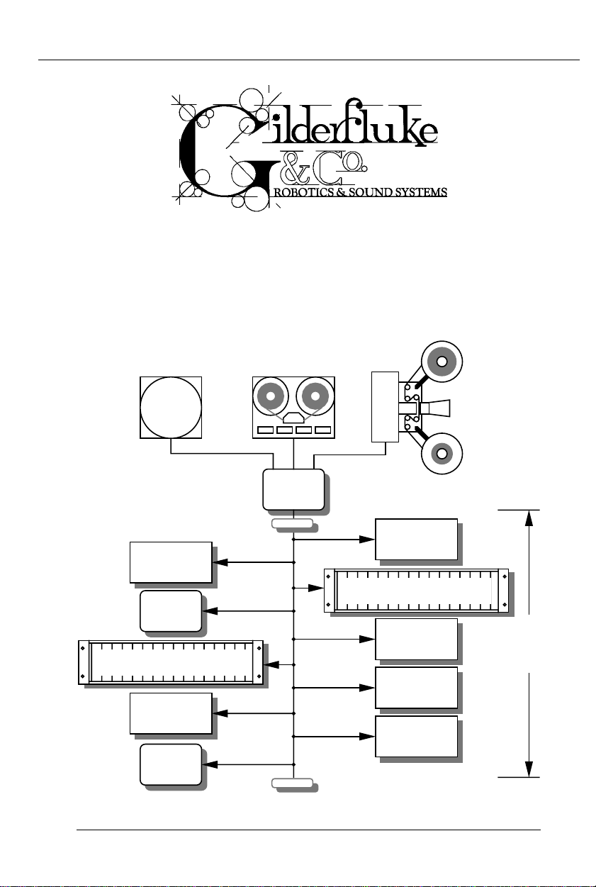
LaserDisk
Player
SMPTE
source
external clock
source
Smart Brick
Heads Up
Display
Card cage with playback-only
Smart Brick Cards
Smart Brick
Heads Up
Display
Brick
Brain
terminator
terminator
playback-only
Smart Brick
Card cage with playback-only
Smart Brick Cards
Smart Brick
up to a mile
playback-only
Smart Brick
playback-only
Smart Brick
Page 2

GILDERFLUKE & CO .• 205 SOUTH FLOWER STREET • BURBANK , CALIFORNIA 91502 • 818/840-9484 • 800/776-5972 • FAX 818/840-9485
AST COAST /FLORIDA O FFICE • 7041 GRAND NATIONAL DRIVE • SUITE 128d • ORLANDO , FL. 32819 • 407/354-5954 • FAX 407/354-5955
E
Safety Disclaimer: Any electronic or mechanical system has a potential to fail. Certain applications using Gilderfluke & Company equipment may involve potential risks of death, personal injury or severe property or environmental damage (“Critical Application”). Gilderfluke
& Company equipment is not designed, intended, authorized or warranted to be suitable in
life support applications, devices or systems or
other critical applications. Inclusion of
Gilderfluke & Company products in such applications is understood to be fully at the risk of
the customer. In order to minimize risks associated with the customer's applications, adequate design and operating safeguards should
be provided by the customer to minimize inherent or procedural hazards.
Gilderfluke & Company assumes no liability
for applications assistance, customer produced
design, software performance, or infringement
of patents or copyrights. Nor does Gilderfluke &
Company warrant or represent that any license,
either express or implied, is granted under any
patent right, copyright, mask work right, or other
intellectual property right of Gilderfluke &
Company covering or relating to any combination, machine, or process in which Gilderfluke &
Company products or services might be or are
used.
Page 3

GILDERFLUKE & CO .• 205 SOUTH FLOWER STREET • BURBANK , CALIFORNIA 91502 • 818/840-9484 • 800/776-5972 • FAX 818/840-9485
AST COAST /FLORIDA O FFICE • 7041 GRAND NATIONAL DRIVE • SUITE 128d • ORLANDO , FL. 32819 • 407/354-5954 • FAX 407/354-5955
E
The Parts of the Smart Brick System .................... 1
BR-MultiBrick32 .................................................................... 2
BS-CRD ................................................................................. 2
BS-ANA .................................................................................. 2
BS-EFB ................................................................................... 2
BS-DMX-Tx ............................................................................ 2
BS-Serial ............................................................................... 3
BR-ZBR .................................................................................. 3
Time Bases .......................................................... 5
LaserDisk (or DVD) ................................................................ 5
Smpte ................................................................................... 6
Internal Time Base ................................................................ 8
External Time Base ............................................................... 9
Smart Brick Configuration .................................... 10
6264LP RAM ........................................................................ 11
62256LP RAM ...................................................................... 12
27C64 Eprom ..................................................................... 13
27C128 Eprom ................................................................... 14
27C256 Eprom ................................................................... 15
27C512 Eprom ................................................................... 16
27C010, 27C020, 27C040 or 27C080 Eprom .................... 17
Enabling the Outputs When Stopped .................................. 18
Disabling the Outputs When Stopped ................................. 19
DMX Forever! ...................................................................... 20
DMX On Occasion .............................................................. 21
J-6 Digital Output Cables .................................... 23
DC Drivers ..................................................................... 26
DPDT relay board ........................................................... 26
Reed relay board ........................................................... 27
I/O module .................................................................... 27
Solid State Relay Fanning Strip ....................................... 27
Smart Brick System Commands ............................ 29
Enter Interactive Echo Mode .............................................. 34
Exit Interactive Echo Mode ................................................. 34
Enter Global Echo Mode ..................................................... 35
Exit Global Echo Mode ....................................................... 35
Enter Echo All Mode ........................................................... 35
Exit Echo All Mode .............................................................. 36
Enter Echo Mode ................................................................ 36
Exit Echo Mode ................................................................... 37
iii of ix
Page 4

GILDERFLUKE & CO .• 205 SOUTH FLOWER STREET • BURBANK , CALIFORNIA 91502 • 818/840-9484 • 800/776-5972 • FAX 818/840-9485
AST COAST /FLORIDA O FFICE • 7041 GRAND NATIONAL DRIVE • SUITE 128d • ORLANDO , FL. 32819 • 407/354-5954 • FAX 407/354-5955
E
Track Status Mode .............................................................. 37
Smart Brick Brain Status ..................................................... 38
Switch Status ...................................................................... 39
Enter Setup Mode ............................................................... 39
Memory Address Status ...................................................... 40
J-6 Port Status .................................................................... 40
Download Configuration .................................................... 40
Upload Configuration ......................................................... 42
Start Commands ................................................................. 42
Start Track ...................................................................... 42
Start Global ................................................................... 42
Start Cocked ................................................................. 42
Start Group .................................................................... 43
Stop Commands ................................................................. 43
Stop Track ...................................................................... 43
Stop Global ................................................................... 43
Stop Cocked ................................................................. 43
Stop Group .................................................................... 43
Reset Commands ............................................................... 43
Reset Track .................................................................... 43
Reset Global .................................................................. 43
Reset Cocked ................................................................ 43
Reset Group .................................................................. 43
Cock Track ......................................................................... 44
Un-Cock Track .................................................................... 44
Un-Cock Global .................................................................. 44
Loop Commands ................................................................ 45
Loop Track ..................................................................... 45
Loop Global ................................................................... 45
Loop Cocked ................................................................. 45
Loop Group ................................................................... 45
Stop at End Commands ...................................................... 46
Stop at End Track ........................................................... 46
Stop at End Global ......................................................... 46
Stop at End Cocked ....................................................... 46
Stop at End Group ......................................................... 46
Select Show Commands ..................................................... 46
Select Show Track .......................................................... 46
Select Show Global ........................................................ 46
Select Show Cocked ...................................................... 46
Select Show ................................................................... 46
Set Brick Address ................................................................ 47
Advance One Frame ........................................................... 47
iv of ix
Page 5

GILDERFLUKE & CO .• 205 SOUTH FLOWER STREET • BURBANK , CALIFORNIA 91502 • 818/840-9484 • 800/776-5972 • FAX 818/840-9485
AST COAST /FLORIDA O FFICE • 7041 GRAND NATIONAL DRIVE • SUITE 128d • ORLANDO , FL. 32819 • 407/354-5954 • FAX 407/354-5955
E
Go Back One Frame ........................................................... 47
Summary of Serial Commands ............................. 48
Rack Smart Brick Brain ....................................... 51
Rack Smart Brick Brain Connections ...................... 52
Rack Smart Brick Brain Messages ......................... 57
Rack Smart Brick Brain Configuration .................... 61
Enter Track Number ............................................................ 63
Baud Rate ........................................................................... 63
LD Serial Port ...................................................................... 64
VT-52 Mode ........................................................................ 64
Numbers ............................................................................. 64
Show Storage ...................................................................... 64
Respond to Group .............................................................. 65
Set Clock ............................................................................ 65
InfraRed Mode .................................................................... 65
Coin-Op Mode ................................................................... 68
Select from J6 .................................................................... 68
Direct Select ....................................................................... 68
Debounce ........................................................................... 69
Running Delay .................................................................... 70
Tape Deck Pulse ................................................................. 70
Error Count ......................................................................... 70
On Startup .......................................................................... 71
Immediate Jumps ............................................................... 71
Countdown Hold ................................................................. 72
Player Type ......................................................................... 72
LaserDisk Time .................................................................... 72
Dropout Protection ............................................................. 72
Print Show Counters ........................................................... 73
Input Triggering Commands ............................................... 74
'GREEN' Input Closing Edge ............................................ 74
'GREEN' Input Opening Edge .......................................... 74
'BLUE' Input Closing Edge ............................................... 74
'BLUE' Input Opening Edge ............................................. 74
'PB' Input Closing Edge ................................................... 74
'PB' Input Opening Edge ................................................. 74
'1/4 J6 Port' Input Closing Edge ...................................... 74
'1/4 J6 Port' Input Opening Edge .................................... 74
Countdown End ............................................................ 74
Pause/Return to Zero (RTZ) ....................................... 76
v of ix
Page 6

GILDERFLUKE & CO .• 205 SOUTH FLOWER STREET • BURBANK , CALIFORNIA 91502 • 818/840-9484 • 800/776-5972 • FAX 818/840-9485
AST COAST /FLORIDA O FFICE • 7041 GRAND NATIONAL DRIVE • SUITE 128d • ORLANDO , FL. 32819 • 407/354-5954 • FAX 407/354-5955
E
Continue/Increment ................................................ 76
Start ........................................................................ 77
Loop ........................................................................ 77
Stop ........................................................................ 78
Stop at End .............................................................. 78
Tape Deck ............................................................... 78
More..... .............................................................................. 80
Load Defaults ...................................................................... 80
Download Configuration .................................................... 80
eXit Setup Mode ................................................................. 82
Rack Smart Brick Brain Show Menu ........................ 84
Show Name ........................................................................ 85
Time Code .......................................................................... 86
Brick Start ........................................................................... 86
Brick End ............................................................................ 86
At End of this Show ............................................................. 86
‘Next’ Show ......................................................................... 88
Frame Rate ......................................................................... 89
Early Starts .......................................................................... 90
Start String .......................................................................... 90
Multi-Disk String ................................................................. 91
End String ........................................................................... 93
LaserDisk Starts .................................................................. 93
LaserDisk 1 ..................................................................... 93
LaserDisk 2 ..................................................................... 93
LaserDisk 3 ..................................................................... 93
LaserDisk 4 ..................................................................... 93
LaserDisk 5 ..................................................................... 93
LaserDisk 6 ..................................................................... 93
LaserDisk 7 ..................................................................... 94
Next Entry ........................................................................... 94
Next In Sequence ............................................................... 94
Last Entry ............................................................................ 94
Kopy Another Show ............................................................. 94
More..... .............................................................................. 95
Load Defaults ...................................................................... 95
Download Configuration .................................................... 95
eXit Setup Mode ................................................................. 97
Rack Smart Brick Brain String Setup Menu ............... 99
Alter Strings ...................................................................... 100
More..... ............................................................................ 100
Load Defaults .................................................................... 100
vi of ix
Page 7

GILDERFLUKE & CO .• 205 SOUTH FLOWER STREET • BURBANK , CALIFORNIA 91502 • 818/840-9484 • 800/776-5972 • FAX 818/840-9485
AST COAST /FLORIDA O FFICE • 7041 GRAND NATIONAL DRIVE • SUITE 128d • ORLANDO , FL. 32819 • 407/354-5954 • FAX 407/354-5955
E
Download Configuration .................................................. 101
eXit Setup Mode ............................................................... 103
Smart Brick Brain Delay Setup Menu ..................... 105
Set Delays ......................................................................... 105
More..... ............................................................................ 105
Load Defaults .................................................................... 106
Download Configuration .................................................. 106
eXit Setup Mode ............................................................... 108
Smart Brick Brain 1/4 J6 Setup Menu .................... 110
Input Triggering Commands ............................................. 110
'1/4 J6 Port' Input Closing Edge .................................... 110
'1/4 J6 Port' Input Opening Edge .................................. 110
Pause/Return to Zero (RTZ) ..................................... 112
Continue/Increment .............................................. 112
Start ...................................................................... 113
Loop ...................................................................... 113
Stop ...................................................................... 114
Stop at End ............................................................ 114
Tape Deck ............................................................. 114
1/4 J6 Input Triggering Commands .................................. 114
Bit 0 Input Closing Edge ............................................... 114
Bit 1 Input Closing Edge ............................................... 114
Bit 2 Input Closing Edge ............................................... 114
Bit 3 Input Closing Edge ............................................... 114
Bit 4 Input Closing Edge ............................................... 114
Bit 5 Input Closing Edge ............................................... 115
Bit 6 Input Closing Edge ............................................... 115
Bit 7 Input Closing Edge ............................................... 115
Sequentially ........................................................... 115
Randomly .............................................................. 115
Normally ................................................................ 116
Select from J6 .................................................................. 116
Direct Select ..................................................................... 116
More..... ............................................................................ 117
Load Defaults .................................................................... 118
Download Configuration .................................................. 118
eXit Setup Mode ............................................................... 120
Smart Brick Brain Schedule Setup Menu ................ 123
Alter Entry ......................................................................... 123
Next Entry ......................................................................... 124
Last Entry .......................................................................... 124
vii of ix
Page 8

GILDERFLUKE & CO .• 205 SOUTH FLOWER STREET • BURBANK , CALIFORNIA 91502 • 818/840-9484 • 800/776-5972 • FAX 818/840-9485
AST COAST /FLORIDA O FFICE • 7041 GRAND NATIONAL DRIVE • SUITE 128d • ORLANDO , FL. 32819 • 407/354-5954 • FAX 407/354-5955
E
Kopy Entry ......................................................................... 124
More..... ............................................................................ 124
Load Defaults .................................................................... 125
Download Configuration .................................................. 125
eXit Setup Mode ............................................................... 127
Smart Brick Brain Calendar Setup Menu ............... 129
Alter Entry ......................................................................... 129
Next Entry ......................................................................... 130
Last Entry .......................................................................... 130
Kopy Entry ......................................................................... 130
More..... ............................................................................ 130
Load Defaults .................................................................... 130
Download Configuration .................................................. 131
enter Keys ........................................................................ 132
eXit Setup Mode ............................................................... 133
Brick Brain Lock Counter/Timer Setup ................... 135
Decrement on any show that plays .............................. 136
Decrement when a specific show plays ....................... 136
Decrement on each minute ........................................ 136
Decrement on each hour ............................................ 137
Tampering ................................................................... 137
Lock Configuration ...................................................... 137
Smart Brick MiniBrain ....................................... 141
Brick Memory Size ............................................................ 143
Brick Memory Size ............................................................ 143
Brick Memory Size ............................................................ 143
Double Show .................................................................... 144
Frame Rate ....................................................................... 144
Stop On Green Opening ................................................... 145
Run Continuous ................................................................ 145
Heads Up Display ............................................ 147
Error Messages ................................................................ 148
Brick Overflow .............................................................. 148
Smpte Time Code Error ................................................ 148
End Of Show ................................................................ 148
String Error ................................................................... 148
Invalid Frame Rate ....................................................... 148
LaserStart Error ............................................................. 149
LaserLoop Error ............................................................ 149
Start Error ..................................................................... 149
viii of ix
Page 9

GILDERFLUKE & CO .• 205 SOUTH FLOWER STREET • BURBANK , CALIFORNIA 91502 • 818/840-9484 • 800/776-5972 • FAX 818/840-9485
AST COAST /FLORIDA O FFICE • 7041 GRAND NATIONAL DRIVE • SUITE 128d • ORLANDO , FL. 32819 • 407/354-5954 • FAX 407/354-5955
E
Response Error ............................................................. 149
Call Home ................................................................... 149
Sending String ............................................................. 150
Starting LaserDisk (or DVD) ............................................ 150
Start and End Strings ........................................ 153
SPECIAL STRING CHARACTERS ............................... 154
End-O-String: (00) ........................................................ 154
LaserSearch: (01) ......................................................... 154
PB: (02) ........................................................................ 154
Blue: (03) ..................................................................... 154
Green:(04) .................................................................. 155
Stop: (05) .................................................................... 155
Play: (06) ..................................................................... 155
Rewind: (07) ................................................................ 155
LaserSearch for CLV LaserDisks (or DVD)s: (08) .............. 156
LaserSearch for CLV LaserDisks (or DVD)s: (09) .............. 156
Don't Care: (80h) ........................................................ 156
ASCII Characters to be Sent Out ............................ 157
ASCII Characters to be Received ........................... 158
PIONEER LaserDisk (or DVD) Commands .......................... 161
SONY LaserDisk Commands ............................................. 167
Panasonic LaserDisk Commands ..................................... 173
HEXadecimal to Decimal to Percentage ....... 178
ix of ix
Page 10

GILDERFLUKE & CO .• 205 SOUTH FLOWER STREET • BURBANK , CALIFORNIA 91502 • 818/840-9484 • 800/776-5972 • FAX 818/840-9485
AST COAST /FLORIDA O FFICE • 7041 GRAND NATIONAL DRIVE • SUITE 128d • ORLANDO , FL. 32819 • 407/354-5954 • FAX 407/354-5955
E
This page was left blank too
x of x
Page 11

GILDERFLUKE & CO .• 205 SOUTH FLOWER STREET • BURBANK , CALIFORNIA 91502 • 818/840-9484 • 800/776-5972 • FAX 818/840-9485
AST COAST /FLORIDA O FFICE • 7041 GRAND NATIONAL DRIVE • SUITE 128d • ORLANDO , FL. 32819 • 407/354-5954 • FAX 407/354-5955
E
- The Parts of the Smart Brick System -
The Smart Brick System is a modular Animation
Control System which consists of One Smart Brick Brain
and any number of Smart Bricks attached to it. Since
the number of Smart Bricks attached to each Smart
Brick Brain is unlimited, Animation Control Systems of
any size to be assembled just by plugging them together.
Smart Brick Systems can be used to control animated shows and displays, fountains, fireworks, lighting,
sound systems, simulators, slide and movie projectors,
fiber optics, window displays, motors, pneumatic and
hydraulic systems, special effects, signs, machines and
machine tools in process control, etc. .............
The Smart Brick Brain is a small microprocessor
controlled unit which can synchronize any number of
Smart Bricks to a LaserDisk (or DVD) player, Smpte time
code, internal time base, or external time base. In addition it can control the LaserDisk (or DVD) player or
tape deck and provide a real time clock or countdown timer for the delay between shows. For all but
the Smpte time code, it can instantly randomly access
any show stored in the system (Smpte synchronized
shows are slaved to whatever show the Smpte time
code is requesting). At the end of any show it can automatically jump to any other show, either with or without a user adjustable delay before playing this next
show. If it is already playing a show and it gets a request for another show, it can be told to ignore the request, store it until done with the current show, or jump
to it immediately.
1 of 178
Page 12

GILDERFLUKE & CO .• 205 SOUTH FLOWER STREET • BURBANK , CALIFORNIA 91502 • 818/840-9484 • 800/776-5972 • FAX 818/840-9485
AST COAST /FLORIDA O FFICE • 7041 GRAND NATIONAL DRIVE • SUITE 128d • ORLANDO , FL. 32819 • 407/354-5954 • FAX 407/354-5955
E
A MiniBrain can be used if you don’t need to syn-
chronize your show with an external time code or randomly access more than two shows.
Smart Brick Brains are attached to the Smart Bricks
by up to a mile of six conductor modular telephone
wire. (This is the same type of wire and connector as
found on the standard Bricks, but is incompatible with
the signals which they use.) Just about any number of
Smart Bricks can be attached to a single Brain (If the
wire runs are long and there are a lot of Smart Bricks
attached, a repeater may be required in the line.)
Make sure that this cable does not have its wires
flipped from one end to the other. If the wire run is
long, then a terminator should be installed at the two
extreme ends of the line.
The Smart Bricks are available in a variety of config-
urations to suit your needs:
• BR-MultiBrick32: Thirty-two output Program-in-Place
Brick.
• BS-CRD: thirty-two output playback-only Smart 'Brick'
card. For mounting in card cages or on standoffs.
Shows are stored in Eprom.
• BS-ANA: Analog Output Smart Brick card. Features six-
teen 0-10 volt and two hundred fifty-six channels of
DMX-512 output. Runs from DMX-512 input or onboard
show data EPROM. (Refer to the BS-ANA manual for de-
tails on this product.)
• BS-EFB: Four Channel Electronic FeedBack Smart Brick
card. Runs from DMX-512 input or EPROM.
• BS-DMX-Tx: DMX-512 output Smart Brick. Sends two hun-
dred fifty-six channels for controlling lighting equipment.
2 of 178
Page 13

GILDERFLUKE & CO .• 205 SOUTH FLOWER STREET • BURBANK , CALIFORNIA 91502 • 818/840-9484 • 800/776-5972 • FAX 818/840-9485
AST COAST /FLORIDA O FFICE • 7041 GRAND NATIONAL DRIVE • SUITE 128d • ORLANDO , FL. 32819 • 407/354-5954 • FAX 407/354-5955
E
(Refer to the BS-DMX-Tx & BS-Serial manual for details on
this product.)
• BS-Serial: As above, but upgraded to control MIDI,
Moog Motion Bases, Rexroth feedback cards, Stepper
controllers, etc. (Refer to the BS-DMX-Tx & BS-Serial manual for details on this product.)
• BR-ZBR: Z-Brick card for use with BS-ANA, BS-DMX-Tx, BS-
Serial or BS-EFB to add thirty-two digital outputs. Card
cage mounted. (Refer to the BS-ANA or BS-DMX-Tx & BSSerial manual for details on this product.)
The Smart Brick System is completely modular. If one
Smart Brick doesn’t have enough outputs, you simply
add more, stacking them until you have enough outputs to do the job.
The Smart Bricks can all be located at one or more
central locations, or they can be built right into whatever it is they are controlling. This latter method allows
you to wire an entire attraction by just stringing up a six
conductor modular telephone line to connect all your
figures. It also allows you to remove a figure’s animation system along with the figure when it is removed for
maintenance, and then run them both on a service
bench away from the rest of the show for testing and
adjustment. A Smart Brick System can consist of any
combination of record/playback Smart Bricks,
playback-only Smart Bricks and card cage mounted
Smart Bricks.
In most cases the Smart Brick system is programmed
using a PC•MACs Animation Control System. Once programmed the show is downloaded to the Smart Brick(s)
and the Smart Brick Brain configured to match the
3 of 178
Page 14

GILDERFLUKE & CO .• 205 SOUTH FLOWER STREET • BURBANK , CALIFORNIA 91502 • 818/840-9484 • 800/776-5972 • FAX 818/840-9485
AST COAST /FLORIDA O FFICE • 7041 GRAND NATIONAL DRIVE • SUITE 128d • ORLANDO , FL. 32819 • 407/354-5954 • FAX 407/354-5955
E
show(s).
Playback-only Smart Bricks store their data in Eprom
type memory chips. This is about the safest way known
to store any type of data. One Eprom is used to store
each individual eight bit wide channel, which means
that when you have to perform a minor change in one
output, you don’t have to replace all the Eproms in the
system. Some newer Smart Bricks store the animation
data in Flash Eproms. These can be programmed in
place by sending the data to the Smart Bricks through
their serial ports.
Quick Start:
When shipped, the Smart Brick Brain is usually configured to start playing show number one
when the 'manual start' pushbutton on its front
is pressed. This show is set up to clock from the
internal time base at thirty frames per second.
To see the system work, attach some Smart
Bricks to the Smart Brick Network connector on
the Smart Brick Brain and plug everything in.
When you push the 'manual start' pushbutton,
you should see the system start clocking
through the frames. Each time you push the
'manual start' button, show number one should
start over from its beginning.
4 of 178
Page 15

GILDERFLUKE & CO .• 205 SOUTH FLOWER STREET • BURBANK , CALIFORNIA 91502 • 818/840-9484 • 800/776-5972 • FAX 818/840-9485
AST COAST /FLORIDA O FFICE • 7041 GRAND NATIONAL DRIVE • SUITE 128d • ORLANDO , FL. 32819 • 407/354-5954 • FAX 407/354-5955
E
- Time Bases -
The Smart Brick System can be used with four normal time bases. If the frame rate is the same for all
shows, you can use any of the time bases within the
same system. The supported time bases are:
1) LaserDisk (or DVD): The Smart Brick Brain has an RS-422
serial port on it which can be attached to the serial port
on many professional quality LaserDisk (or DVD) players.
The Smart Brick Brain talks to the LaserDisk (or DVD) player
to synchronize the entire system to the show being
played. All control for the LaserDisk (or DVD) player is provided by the Smart Brick Brain. Systems with LaserDisk (or
DVD) players in them are limited to running either fifteen,
twenty-five or thirty Frames Per Second (FPS), as these are
the frame rates for the video reproduction.
The LaserDisk (or DVD) players which are currently
supported are the Pioneer ‘LD-’, Sony ‘LDP-’ and selected
Panasonic players. The Pioneer LaserDisk (or DVD) code
was developed and tested on an LD-V8000, which is
Pioneer’s top of the line unit. It should be compatible with
all of the earlier models in this series as well. The advantages of the LD-V8000 are: four audio channels (two
analog and two digital), frame memory during random
access, separate front panel controls, and faster access
times than all of its predecessors.
The Sony LaserDisk code was developed and tested
on an LDP-2000. It should be compatible with all of the
other models in this series as well.
If more than a single LaserDisk (or DVD) is to be controlled from a single Smart Brick System, then a LaserDisk
Multiplexer must be used. Each of these allow seven
LaserDisk (or DVD) players to be connected to the Rack
5 of 178
Page 16

GILDERFLUKE & CO .• 205 SOUTH FLOWER STREET • BURBANK , CALIFORNIA 91502 • 818/840-9484 • 800/776-5972 • FAX 818/840-9485
AST COAST /FLORIDA O FFICE • 7041 GRAND NATIONAL DRIVE • SUITE 128d • ORLANDO , FL. 32819 • 407/354-5954 • FAX 407/354-5955
E
Smart Brick Brain.
LaserDisks are available in two different recording for-
mats. These are Constant Angular Velocity (CAV) and
Constant Linear Velocity (CAV). Either can be made to
work, but the CAV format is preferred. It is the only format
in which all of the LaserDisk players’ commands are supported
2) Smpte: (pronounced “SIMP-T“) is a time code which was
developed by the Society of Motion Picture and
Television Electronics for use in audio, film, and television
production. It is normally recorded on a spare audio
track on the medium being used (audio tape, video
tape, or film), and then used to synchronize various
pieces of compatible equipment together. As an industry standard, virtually every audio, video or film studio will
have the equipment to lay down a Smpte time code
track.
Smpte is usually recorded at thirty frames per second
(although twenty-five frames per second is used in
Europe and places where this is the normal television frequency, and twenty-four frames per second is occasionally used in film production). What this means is that
thirty (or twenty-four or twenty-five) times each second a
number is recorded on the tape or film which represents
the hours, seconds, minutes and frame (00:00:00.00)
represented by this particular little stretch of medium.
Since each little stretch is represented by a unique number, Smpte is known as an ‘absolute’ time code. No matter where the tape is, the Smart Brick Brain will instantly
evaluate the numbers it gets from the Smpte time code,
and play the appropriate animation data.
With Smpte synchronized shows, the Smpte ‘hour’ is
used to tell the Smart Brick Brain which show it is actually
6 of 178
Page 17

GILDERFLUKE & CO .• 205 SOUTH FLOWER STREET • BURBANK , CALIFORNIA 91502 • 818/840-9484 • 800/776-5972 • FAX 818/840-9485
AST COAST /FLORIDA O FFICE • 7041 GRAND NATIONAL DRIVE • SUITE 128d • ORLANDO , FL. 32819 • 407/354-5954 • FAX 407/354-5955
E
running. The ‘hours’ Smpte supports are 00 through 23 to
give you twenty-four possible Smpte synchronized shows
(Smpte hour ‘00’ is mapped to show number ‘24’ by the
Smart Brick Brain, since 00 isn’t a valid show number).
Any individual show can be as long as an hour. When
told to start running a Smpte show, the Smart Brick Brain
will start listening for any Smpte coming in. When it picks
up a good Smpte signal, it looks at the ‘hour’, and then
checks to see if it is the number of a Smpte synchronized
show, and if so, plays it. Note that if the show number the
Smart Brick Brain expects to be played when it starts listening for the Smpte is not the show number it actually
receives, it will play the latter. If the show number it receives isn’t assigned as a Smpte show, then it will display
an error message on the Heads Up Display and not
play anything. For this reason random access commands for Smpte synchronized shows are somewhat at
the mercy of whatever Smpte hour is actually received
from the Smpte source.
If more than twenty-four Smpte synchronized shows
are required, you can use an output from the animation
system to stop the system ‘mid show’. This technique can
be used to break up a single long show into as many
shorter sequences as you would like.
Since Smpte is often provided by an audio or video
tape deck, the Smart Brick Brain has three outputs which
can be programmed to send signals to the tape deck
at the beginnings and ends of the shows. These are typically used to start, stop and rewind the tape deck. These
outputs are simple relay closures, which can usually be
attached directly to the remote control inputs on a tape
deck.
Frame rates supported by the Smart Brick Brain are
7 of 178
Page 18

GILDERFLUKE & CO .• 205 SOUTH FLOWER STREET • BURBANK , CALIFORNIA 91502 • 818/840-9484 • 800/776-5972 • FAX 818/840-9485
AST COAST /FLORIDA O FFICE • 7041 GRAND NATIONAL DRIVE • SUITE 128d • ORLANDO , FL. 32819 • 407/354-5954 • FAX 407/354-5955
E
fifteen or thirty FPS when using Smpte recorded at thirty
FPS, twenty-five FPS when using Smpte recorded at
twenty-five FPS, and twelve or twenty-four FPS when using
Smpte recorded at twenty-four FPS. All type of Smpte
must be recorded ‘non-drop frame’ for compatibility with
the Smart Brick Brain.
Smpte is a type of time code which is prone to minor
errors. The Smart Brick Brain automatically bridges over
these until it gets a number of consecutive consistent
Smpte frames. You can set the size of this number when
configuring the Smart Brick Brain to anywhere from one
to two hundred fifty-six consecutive frames.
3) Internal Time Base: If there is no need for synchroniza-
tion to an audio or video source, you can use the crystal
controlled time base in the Smart Brick Brain to clock the
entire system. This type of show is often used for chase
sequences, test shows, when you just don’t need to synchronize a show to anything else, or to keep the figures
moving between the main Smpte or LaserDisk (or DVD)
synchronized shows. Frame rates supported are:
1 FPS
2 FPS
4 FPS
5 FPS
8 FPS
10 FPS
12 FPS
15 FPS
16 FPS
20 FPS
24 FPS
25 FPS
30 FPS
8 of 178
Page 19

GILDERFLUKE & CO .• 205 SOUTH FLOWER STREET • BURBANK , CALIFORNIA 91502 • 818/840-9484 • 800/776-5972 • FAX 818/840-9485
AST COAST /FLORIDA O FFICE • 7041 GRAND NATIONAL DRIVE • SUITE 128d • ORLANDO , FL. 32819 • 407/354-5954 • FAX 407/354-5955
E
32 FPS
50 FPS
60 FPS
64 FPS
75 FPS
100 FPS)
4) External Time Base: This is generally used when you
need to tie the Smart Brick System to an external clock.
Typical uses of external time base sync are to lock the
system to a mechanical device like a motion picture
camera or projector so that it will follow at any speed, or
to synchronize two incompatible systems so that data
can be transferred between the two. Frame rates supported are from one to one hundred FPS (this is simply
the number of frames displayed on the Heads Up
Display, as the actual rate will follow whatever clock rate
is fed to the Smart Brick Brain).
9 of 178
Page 20

GILDERFLUKE & CO .• 205 SOUTH FLOWER STREET • BURBANK , CALIFORNIA 91502 • 818/840-9484 • 800/776-5972 • FAX 818/840-9485
AST COAST /FLORIDA O FFICE • 7041 GRAND NATIONAL DRIVE • SUITE 128d • ORLANDO , FL. 32819 • 407/354-5954 • FAX 407/354-5955
E
- Smart Brick Configuration -
The majority of the configuration for the Smart Bricks is handled in the Smart Brick Brain. The exceptions to this are those
jumpers which set the size and type of memory used in each
Smart Brick, and whether or not you would like the outputs from a
Smart Brick to be disabled when ever the system is not advancing frames.
The one jumper which the Smart Bricks have on them retain
the same callout as are used in the normal Micro MACs Bricks. All
configuration is done on JP-2. The two things which Smart Bricks
must be configured for are the memory size and type and the
‘enable/disable when stopped’.
In all of the following drawings, the jumper pins are shown as
circles contained within an outline of the header assembly. Pins
which are used for a given configuration are shown as filled-in,
while those which remain hollow are not being used. The jumper
plugs (used for connecting adjacent pins)or wires (used for connecting pins which are not adjacent) which connect the pins are
shown as black lines. Any pin which is shown filled in with black,
but which does not have any wire or jumper plug shown on it,
must have all wires and/or jumper plugs removed from it in the
actual Smart Brick you are configuring.
10 of 178
Page 21
GILDERFLUKE & CO .• 205 SOUTH FLOWER STREET • BURBANK , CALIFORNIA 91502 • 818/840-9484 • 800/776-5972 • FAX 818/840-9485
AST COAST /FLORIDA O FFICE • 7041 GRAND NATIONAL DRIVE • SUITE 128d • ORLANDO , FL. 32819 • 407/354-5954 • FAX 407/354-5955
E
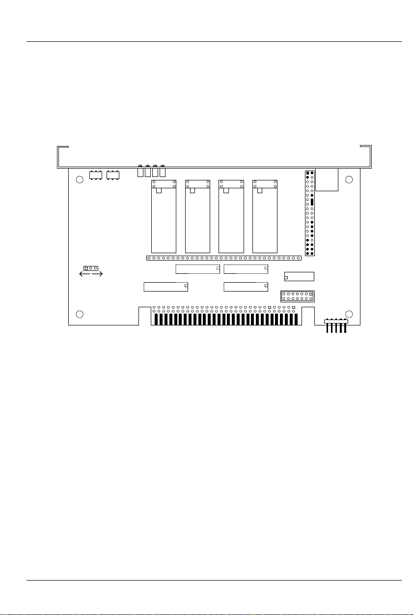
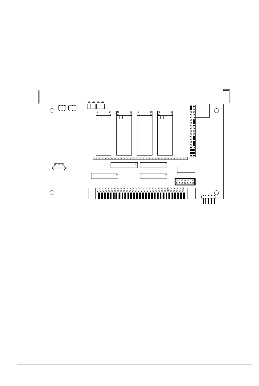
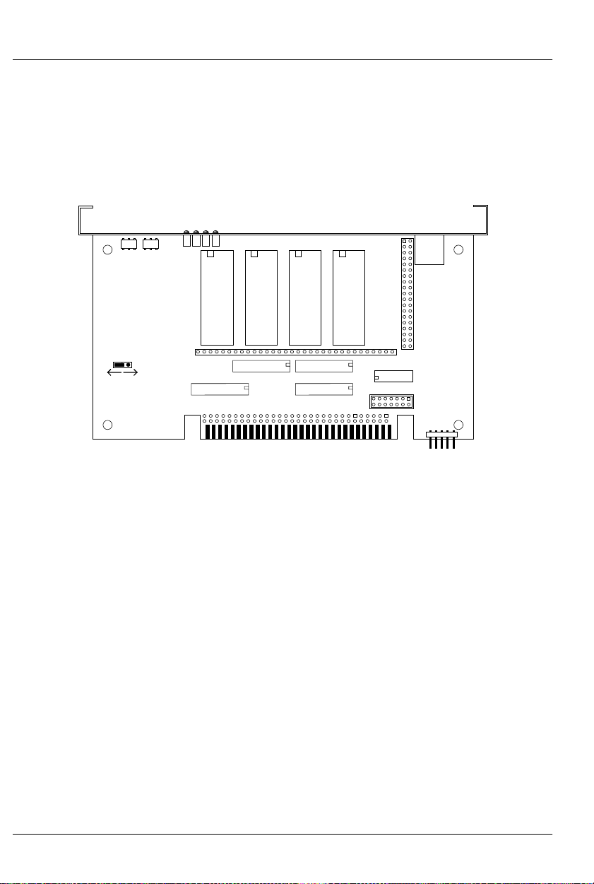
- 6264LP RAM -
To configure a Record/Playback Smart Brick for use with
6264LP static RAM Chips for a capacity of 16,384 (16K) frames.
As shown, the RAM chips must be ‘South’ justified, leaving four unused holes at the top of each socket.
DMX data
DMX
heart
DMX Error
DMX-512 Address
Brain heart
6264LP 6264LP 6264LP 6264LP
JP2
DMX-
512
in/out
DMX-512
Forever!
Yes No
channel
3
U5
channel
U6
U11 (ch 3)
2
channel
U12 (ch 2)
channel
1
U7
0
U8
U13 (ch 1)
U14 (ch 0)
JP3
U17 26LS32
JP6
11 of 178
Page 22
GILDERFLUKE & CO .• 205 SOUTH FLOWER STREET • BURBANK , CALIFORNIA 91502 • 818/840-9484 • 800/776-5972 • FAX 818/840-9485
AST COAST /FLORIDA O FFICE • 7041 GRAND NATIONAL DRIVE • SUITE 128d • ORLANDO , FL. 32819 • 407/354-5954 • FAX 407/354-5955
E
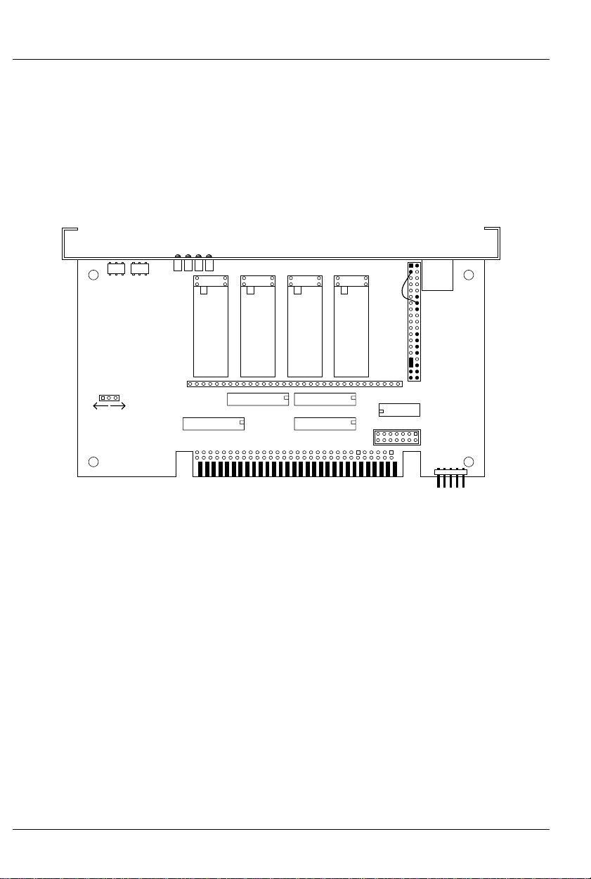
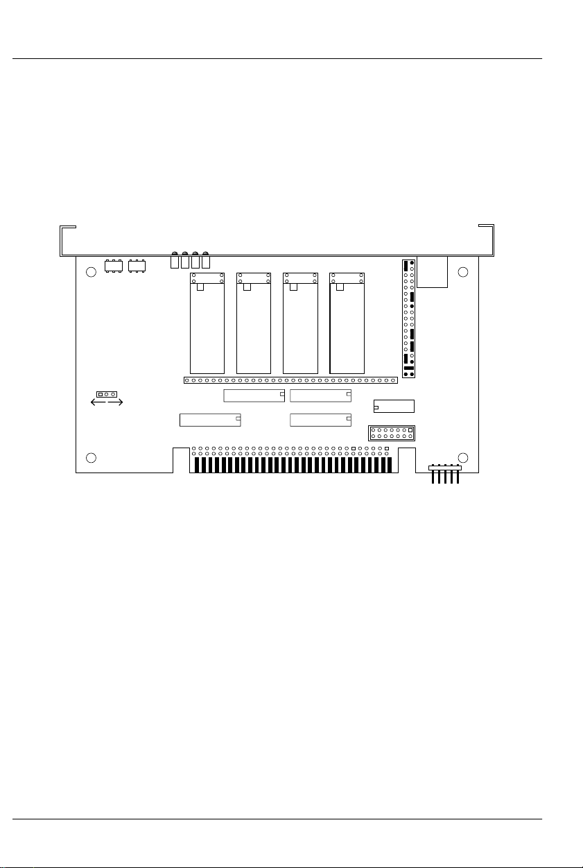
- 62256LP RAM -
To configure a Record/Playback Smart Brick for use with
62256LP static RAM Chips for a capacity of 65,536 (64K). As
shown, the RAM chips must be ‘South’ justified, leaving four unused holes at the top of each socket. This configuration requires
a wire wrapped jumper.
DMX data
DMX
DMX Error
heart
DMX-512 Address
Brain heart
62256LP 62256LP 62256LP 62256LP
JP2
DMX-
512
in/out
DMX-512
Forever!
Yes No
channel
3
U5
channel
U6
U11 (ch 3)
2
channel
U12 (ch 2)
channel
1
U7
0
U8
U13 (ch 1)
U14 (ch 0)
JP3
U17 26LS32
JP6
12 of 178
Page 23

GILDERFLUKE & CO .• 205 SOUTH FLOWER STREET • BURBANK , CALIFORNIA 91502 • 818/840-9484 • 800/776-5972 • FAX 818/840-9485
AST COAST /FLORIDA O FFICE • 7041 GRAND NATIONAL DRIVE • SUITE 128d • ORLANDO , FL. 32819 • 407/354-5954 • FAX 407/354-5955
E
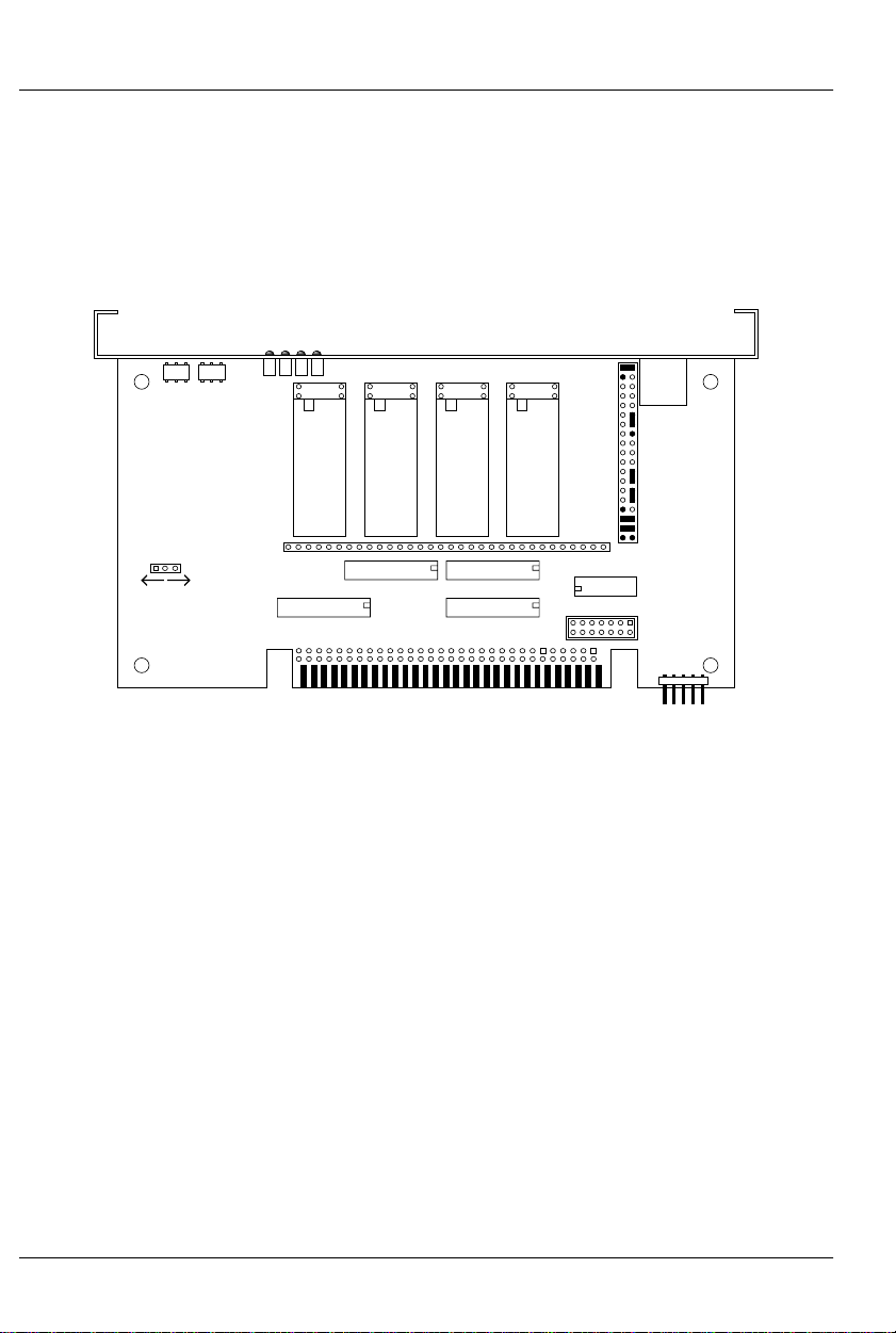
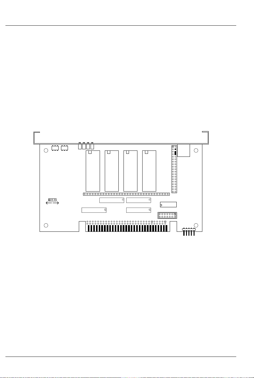
- 27C64 Eprom -
To configure a Playback-only Smart Brick for use with 27C64
Eprom Chips for a capacity of 8192 (8 K) frames. The Eprom
chips must be ‘South’ justified, leaving four unused holes at the
top of each socket.
DMX data
DMX
DMX Error
heart
DMX-512 Address
Brain heart
27C64 27C64 27C64 27C64
JP2
DMX-
512
in/out
DMX-512
Forever!
Yes No
channel
3
U5
channel
U11 (ch 3)
2
U6
channel
U12 (ch 2)
channel
1
U7
0
U8
U13 (ch 1)
U14 (ch 0)
JP3
U17 26LS32
JP6
13 of 178
Page 24
GILDERFLUKE & CO .• 205 SOUTH FLOWER STREET • BURBANK , CALIFORNIA 91502 • 818/840-9484 • 800/776-5972 • FAX 818/840-9485
AST COAST /FLORIDA O FFICE • 7041 GRAND NATIONAL DRIVE • SUITE 128d • ORLANDO , FL. 32819 • 407/354-5954 • FAX 407/354-5955
E
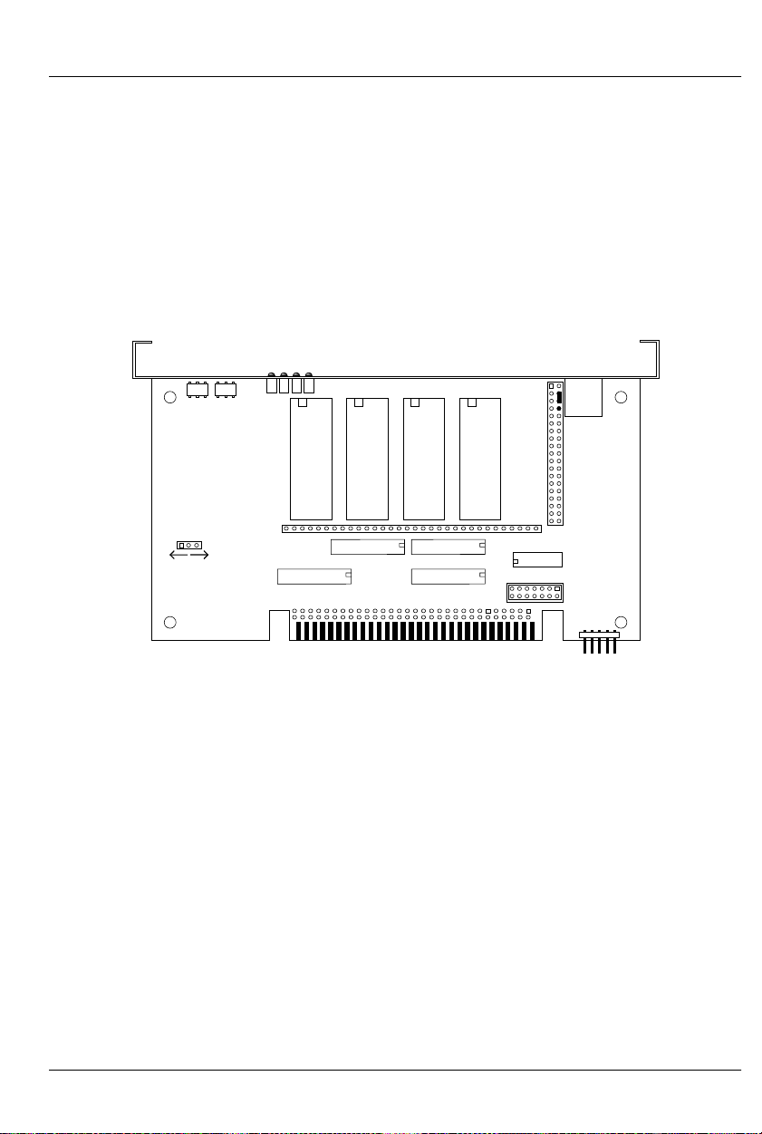
- 27C128 Eprom -
To configure a Playback-only Smart Brick for use with 27C128
Eprom Chips for a capacity of 16,384 (16K) frames. The Eprom
chips must be ‘South’ justified, leaving four unused holes at the
top of each socket.
DMX data
DMX
DMX Error
heart
DMX-512 Address
Brain heart
27C128 27C128 27C128 27C128
JP2
DMX-
512
in/out
DMX-512
Forever!
Yes No
channel
3
U5
channel
U6
U11 (ch 3)
2
channel
U12 (ch 2)
channel
1
U7
0
U8
U13 (ch 1)
U14 (ch 0)
JP3
U17 26LS32
JP6
14 of 178
Page 25
GILDERFLUKE & CO .• 205 SOUTH FLOWER STREET • BURBANK , CALIFORNIA 91502 • 818/840-9484 • 800/776-5972 • FAX 818/840-9485
AST COAST /FLORIDA O FFICE • 7041 GRAND NATIONAL DRIVE • SUITE 128d • ORLANDO , FL. 32819 • 407/354-5954 • FAX 407/354-5955
E
- 27C256 Eprom -
To configure a Playback-only Smart Brick for use with 27C256
Eprom Chips for a capacity of 32,768 (32 K) frames. The Eprom
chips must be ‘South’ justified, leaving four unused holes at the
top of each socket.
DMX data
DMX
DMX Error
heart
DMX-512 Address
Brain heart
27C256 27C256 27C256 27C256
JP2
DMX-
512
in/out
DMX-512
Forever!
Yes No
channel
3
U5
channel
U11 (ch 3)
2
U6
channel
U12 (ch 2)
channel
1
U7
0
U8
U13 (ch 1)
U14 (ch 0)
JP3
U17 26LS32
JP6
15 of 178
Page 26
GILDERFLUKE & CO .• 205 SOUTH FLOWER STREET • BURBANK , CALIFORNIA 91502 • 818/840-9484 • 800/776-5972 • FAX 818/840-9485
AST COAST /FLORIDA O FFICE • 7041 GRAND NATIONAL DRIVE • SUITE 128d • ORLANDO , FL. 32819 • 407/354-5954 • FAX 407/354-5955
E
- 27C512 Eprom -
To configure a Playback-only Smart Brick for use with 27C512
Eprom Chips for a capacity of 65,536 (64K) frames. This is the default memory configuration for Smart Bricks. The Eprom chips
must be ‘South’ justified, leaving four unused holes at the top of
each socket.
DMX data
DMX Error
DMX
heart
DMX-512 Address
Brain heart
27C512 27C512 27C512 27C512
JP2
DMX-
512
in/out
DMX-512
Forever!
Yes
channel
1
U7
0
U8
U13 (ch 1)
U14 (ch 0)
JP3
U17 26LS32
JP6
3
U5
channel
U11 (ch 3)
channel
No
U6
2
channel
U12 (ch 2)
16 of 178
Page 27

GILDERFLUKE & CO .• 205 SOUTH FLOWER STREET • BURBANK , CALIFORNIA 91502 • 818/840-9484 • 800/776-5972 • FAX 818/840-9485
AST COAST /FLORIDA O FFICE • 7041 GRAND NATIONAL DRIVE • SUITE 128d • ORLANDO , FL. 32819 • 407/354-5954 • FAX 407/354-5955
E
- 27C010, 27C020, 27C040 or 27C080
Eprom -
To configure a Playback-only Smart Brick for use with:
27C010 Eprom for a capacity of 131,072 (128 K) frames
27C020 Eprom for a capacity of 262,144 (256 K) frames
27C040 Eprom for a capacity of 524,288 (512 K) frames
27C080 Eprom for a capacity of 1,048,576 (1024 K) frames
DMX data
DMX
heart
DMX Error
DMX-512 Address
Brain heart
27C010
27C020
27C040
27C080
27C010
27C020
27C040
27C080
27C010
27C020
27C040
27C080
27C010
27C020
27C040
27C080
JP2
DMX-
512
in/out
DMX-512
Forever!
Yes
channel
1
U7
0
U8
U13 (ch 1)
U14 (ch 0)
JP3
U17 26LS32
JP6
U5
3
channel
U11 (ch 3)
channel
No
U6
2
channel
U12 (ch 2)
17 of 178
Page 28
GILDERFLUKE & CO .• 205 SOUTH FLOWER STREET • BURBANK , CALIFORNIA 91502 • 818/840-9484 • 800/776-5972 • FAX 818/840-9485
AST COAST /FLORIDA O FFICE • 7041 GRAND NATIONAL DRIVE • SUITE 128d • ORLANDO , FL. 32819 • 407/354-5954 • FAX 407/354-5955
E
- Enabling the Outputs When Stopped -
This jumper plug must be installed for the Smart Brick to work. It
has two possible positions. This position should be used if you
want the outputs to be active at their programmed levels, even
when the system is not advancing frames. This is used if you
don’t care that some outputs might stay on even when the system is no longer advancing frames. It is almost always used if
there are any analog functions attached to a Smart Brick, as disabling the outputs which feed a D/A converter would cause it to
slam to one of it’s extremes.
DMX data
DMX
heart
DMX Error
DMX-512 Address
Brain heart
JP2
DMX-
512
in/out
DMX-512
Forever!
Yes
2
U6
channel
U12 (ch 2)
channel
No
channel
3
U5
U11 (ch 3)
channel
1
U7
0
U8
U13 (ch 1)
U14 (ch 0)
JP3
U17 26LS32
JP6
18 of 178
Page 29
GILDERFLUKE & CO .• 205 SOUTH FLOWER STREET • BURBANK , CALIFORNIA 91502 • 818/840-9484 • 800/776-5972 • FAX 818/840-9485
AST COAST /FLORIDA O FFICE • 7041 GRAND NATIONAL DRIVE • SUITE 128d • ORLANDO , FL. 32819 • 407/354-5954 • FAX 407/354-5955
E
- Disabling the Outputs When Stopped -
This jumper plug must be installed for the Smart Brick to work. It
has two possible positions. This position will cause all of the outputs to turn off whenever the Smart Brick System stops advancing
frames and the ‘running delay’ counter has run out. This is useful
if damage might result from leaving certain outputs in your system turned on indefinitely, as could occur if the system were
stopped while those outputs were active.
DMX data
DMX
heart
DMX Error
DMX-512 Address
Brain heart
JP2
DMX-
512
in/out
DMX-512
Forever!
Yes No
channel
3
U5
channel
U6
U11 (ch 3)
2
channel
U12 (ch 2)
channel
1
U7
0
U8
U13 (ch 1)
U14 (ch 0)
JP3
U17 26LS32
JP6
19 of 178
Page 30
GILDERFLUKE & CO .• 205 SOUTH FLOWER STREET • BURBANK , CALIFORNIA 91502 • 818/840-9484 • 800/776-5972 • FAX 818/840-9485
AST COAST /FLORIDA O FFICE • 7041 GRAND NATIONAL DRIVE • SUITE 128d • ORLANDO , FL. 32819 • 407/354-5954 • FAX 407/354-5955
E
- DMX Forever! -
This jumper plug is available only on Smart Bricks that have
the DMX-512 option installed. If set to ‘Yes’, data on the outputs
retains the last DMX-512 data that was received until new DMX512 data is received.
DMX data
DMX
heart
DMX Error
DMX-512 Address
Brain heart
JP2
DMX-
512
in/out
DMX-512
Forever!
Yes No
channel
3
U5
channel
U6
U11 (ch 3)
2
channel
U12 (ch 2)
channel
1
U7
0
U8
U13 (ch 1)
U14 (ch 0)
JP3
U17 26LS32
JP6
20 of 178
Page 31

GILDERFLUKE & CO .• 205 SOUTH FLOWER STREET • BURBANK , CALIFORNIA 91502 • 818/840-9484 • 800/776-5972 • FAX 818/840-9485
AST COAST /FLORIDA O FFICE • 7041 GRAND NATIONAL DRIVE • SUITE 128d • ORLANDO , FL. 32819 • 407/354-5954 • FAX 407/354-5955
E
- DMX On Occasion -
This jumper plug is available only on Smart Bricks that have
the DMX-512 option installed. If it is in the ‘NO’ position, the card
reverts to outputting data from the on-board Eproms when the
DMX-512 signal goes away.
DMX data
DMX
heart
DMX Error
DMX-512 Address
Brain heart
JP2
DMX-
512
in/out
DMX-512
Forever!
Yes No
channel
3
U5
channel
U11 (ch 3)
2
U6
channel
U12 (ch 2)
channel
1
U7
0
U8
U13 (ch 1)
U14 (ch 0)
JP3
U17 26LS32
JP6
21 of 178
Page 32

GILDERFLUKE & CO .• 205 SOUTH FLOWER STREET • BURBANK , CALIFORNIA 91502 • 818/840-9484 • 800/776-5972 • FAX 818/840-9485
AST COAST /FLORIDA O FFICE • 7041 GRAND NATIONAL DRIVE • SUITE 128d • ORLANDO , FL. 32819 • 407/354-5954 • FAX 407/354-5955
E
Is this the second or third blank page?
22 of 178
Page 33

k
GILDERFLUKE & CO .• 205 SOUTH FLOWER STREET • BURBANK , CALIFORNIA 91502 • 818/840-9484 • 800/776-5972 • FAX 818/840-9485
AST COAST /FLORIDA O FFICE • 7041 GRAND NATIONAL DRIVE • SUITE 128d • ORLANDO , FL. 32819 • 407/354-5954 • FAX 407/354-5955
E
- J-6 Digital Output Cables -
In all animation systems made by Gilderfluke & Company all
input and output cabling on the Smart Bricks is through what we
call ‘J-6’ standard output cables. These are 40 wire cables which
are made up of four identical eight bit wide ‘channels’. A J-6
cable is often split up into four individual channels. As each
channel also includes a common power supply and ground
wire, each ‘1/4 J-6’ cable is made up of ten wires, and can be
used to control eight individual ‘digital’ (off/on) devices, or one
eight bit wide ‘analog’ device.
In all animation systems made by Gilderfluke & Company, all
outputs are open collector switches to ground, and all inputs are
opto isolators. Flyback diodes are included in the outputs for driving inductive loads:
fuse
flybac
supply supply
diode
typical output
typical input
To simplify wiring to any MACs animation system, the connectors used on the J-6 cables are what are called ‘insulation displacement connectors’. These simply snap on to an entire cable,
automatically ‘displacing’ the wire insulation and making contact with the wires within. This means that an entire 40 wire cable
can be terminated in seconds. All connectors are polarized, to
keep them from being plugged in backwards. Although there
are tools made specifically for installing these connectors, the
tool we find works best is a small bench vise.
23 of 178
Page 34

(
-
-
d
d
d
d
d
-
(
-
-
GILDERFLUKE & CO .• 205 SOUTH FLOWER STREET • BURBANK , CALIFORNIA 91502 • 818/840-9484 • 800/776-5972 • FAX 818/840-9485
AST COAST /FLORIDA O FFICE • 7041 GRAND NATIONAL DRIVE • SUITE 128d • ORLANDO , FL. 32819 • 407/354-5954 • FAX 407/354-5955
E
Any eight digital devices or one eight bit analog device can
be connected to any 1/4 J-6 cable as shown. The LED between
the ground (pin #1 brown) wire and supply (pin #10 black) wire
acts as an indicator which is lit if the fuse for that channel is OK:
#1 ground (brown)--
#2 bit 7 (red)--
#3 bit 6 (orange)--
#4 bit 5 (yellow)--
#5 bit 4 (green)--
#6 bit 3 (blue)--
violet)-
#7 bit 2
#8 bit 1 (grey)--
#9 bit 0 (white)--
#10 supply (black)-
loa
load
loa
load
loa
loa
load
loa
LED
#1 ground (brown)--
2.2 K ohm
1/4 watt resistor
#10 supply (black)-
#2 bit 7 (red)--
#3 bit 6 (orange)--
#4 bit 5 (yellow)--
#5 bit 4 (green)-
#6 bit 3 (blue)--
#7 bit 2
violet)-
#8 bit 1 (grey)--
#9 bit 0 (white)--
any
eight bit
analog
device
The supply line for each 1/4 J-6 is fused for one amp. You
should treat each 1/4 J-6 as an individual, and not cross the outputs or supply lines from one channel to the lines from any other
channel. Doing this won’t cause any damage, but can reduce
the protection for the outputs that the fuses normally provide.
24 of 178
Page 35

GILDERFLUKE & CO .• 205 SOUTH FLOWER STREET • BURBANK , CALIFORNIA 91502 • 818/840-9484 • 800/776-5972 • FAX 818/840-9485
AST COAST /FLORIDA O FFICE • 7041 GRAND NATIONAL DRIVE • SUITE 128d • ORLANDO , FL. 32819 • 407/354-5954 • FAX 407/354-5955
E
Each J-6 cable is arranged in the following order:
wire number color wire function
1 brown circuit ground
2 red channel 0 data bit 7
3 orange channel 0 data bit 6
4 yellow channel 0 data bit 5
5 green channel 0 data bit 4
6 blue channel 0 data bit 3
7 violet channel 0 data bit 2
8 gray channel 0 data bit 1
9 white channel 0 data bit 0
10 black + unregulated power supply (fused for 1 amp)
11 brown circuit ground
12 red channel 1 data bit 7
13 orange channel 1 data bit 6
14 yellow channel 1 data bit 5
15 green channel 1 data bit 4
16 blue channel 1 data bit 3
17 violet channel 1 data bit 2
18 gray channel 1 data bit 1
19 white channel 1 data bit 0
20 black + unregulated power supply (fused for 1 amp)
21 brown circuit ground
22 red channel 2 data bit 7
23 orange channel 2 data bit 6
24 yellow channel 2 data bit 5
25 green channel 2 data bit 4
26 blue channel 2 data bit 3
27 violet channel 2 data bit 2
28 gray channel 2 data bit 1
29 white channel 2 data bit 0
30 black + unregulated power supply (fused for 1 amp)
31 brown circuit ground
32 red channel 3 data bit 7
33 orange channel 3 data bit 6
34 yellow channel 3 data bit 5
35 green channel 3 data bit 4
36 blue channel 3 data bit 3
37 violet channel 3 data bit 2
38 gray channel 3 data bit 1
39 white channel 3 data bit 0
40 black +unregulated power supply (fused for 1 amp)
25 of 178
Page 36

GILDERFLUKE & CO .• 205 SOUTH FLOWER STREET • BURBANK , CALIFORNIA 91502 • 818/840-9484 • 800/776-5972 • FAX 818/840-9485
AST COAST /FLORIDA O FFICE • 7041 GRAND NATIONAL DRIVE • SUITE 128d • ORLANDO , FL. 32819 • 407/354-5954 • FAX 407/354-5955
E
The current Output Capacity of a each output is as shown in
the following chart:
Peak Collector Current as a function
600ma.
500ma.
400ma.
300ma.
200ma.
Allowable Peak Collector Current @ 70ºC
100ma.
Number of outputs
conducting
simultaneously
of Output Duty Cycle
7
8
2
3
4
5
10% 20% 30% 40% 50% 60% 70% 80% 90% 100%
Output Duty Cycle
Since it is unusual to have more than 50% of the outputs on
at any one time, you can usually assume the system has a 250
ma output current capacity. If you are going to be turning on lots
of heavy loads at the same time, you should derate this to 150
ma.. This is sufficient to drive the majority of loads which will be directly connected to the outputs of the animation system. If additional current capacity is needed, or if you need to drive higher
voltage loads, you can connect relays as needed to the outputs
of the animation system. Coincidentally, boards for doing this
are available from Gilderfluke & Company. These include:
DC Drivers: These are a series of eight channel high current
DC drivers manufactured by Gilderfluke & Company.
Outputs capacities range from 700 ma. to 3.5 amps
per output.
DPDT relay board: A set of eight electromechanical relays
with double pole/double throw contacts rated at 5
amps each.
26 of 178
Page 37

GILDERFLUKE & CO .• 205 SOUTH FLOWER STREET • BURBANK , CALIFORNIA 91502 • 818/840-9484 • 800/776-5972 • FAX 818/840-9485
AST COAST /FLORIDA O FFICE • 7041 GRAND NATIONAL DRIVE • SUITE 128d • ORLANDO , FL. 32819 • 407/354-5954 • FAX 407/354-5955
E
Reed relay board: A set of eight small electromechanical
relays with normally open contacts rated at 150 ma
each.
I/O module: A set of eight small solid state relays with nor-
mally open contacts rated at 3.5 amps each (AC and
DC relays available).
Solid State Relay Fanning Strip: For connecting up to eight
popular ‘hockey puck’ style relays to a 1/4 J-6 output
cable. These are available with capacities of up to 75
amps each.
27 of 178
Page 38

GILDERFLUKE & CO .• 205 SOUTH FLOWER STREET • BURBANK , CALIFORNIA 91502 • 818/840-9484 • 800/776-5972 • FAX 818/840-9485
AST COAST /FLORIDA O FFICE • 7041 GRAND NATIONAL DRIVE • SUITE 128d • ORLANDO , FL. 32819 • 407/354-5954 • FAX 407/354-5955
E
Is this the third or fourth blank page?
28 of 178
Page 39

GILDERFLUKE & CO .• 205 SOUTH FLOWER STREET • BURBANK , CALIFORNIA 91502 • 818/840-9484 • 800/776-5972 • FAX 818/840-9485
AST COAST /FLORIDA O FFICE • 7041 GRAND NATIONAL DRIVE • SUITE 128d • ORLANDO , FL. 32819 • 407/354-5954 • FAX 407/354-5955
E
- Smart Brick System Commands -
The MACs Smart Brick System can be controlled by simple
switch closures to start and stop playback or cycling, randomly
select shows, and perform a variety of functions. The Rack
Mounted Smart Brick Brain can also start shows based on the
time of day or countdowns between shows. In addition, you can
talk to any combination of up to two hundred fifty-six Smart Brick
Systems and Digital Audio Repeaters at one time through a serial
data line from your computer, terminal, or control system.
This same serial port must be used to configure the features of
any Smart Brick System, and is used by the system when it needs
to talk to a LaserDisk (or DVD) player or any other serially controlled device. The latter limits the use of the serial port to those
systems which are not controlling LaserDisk (or DVD) players.
All commands sent to the MACs Smart Brick System through its
serial interface take the following format. All characters are sent in
ASCII. All numeric values are sent in HEXadecimal (HEX for short),
and consist of one or more ASCII characters (0-9, A through F).
The case (as in upper and lower) of all input is important. A lower
case 'a' signifies a command, while an 'A' is a numeric value. If
the Smart Brick System receives another command while it is waiting for additional input needed to complete the previous command, it will abandon the previous command and start working
on the new one.
In the following documentation any input you will send to the
audio system is shown in outline. The response to a command is
shown in italics.
If the Smart Brick System is in a mode where you expect to receive some response from it (generally in one of the echo
modes), you must wait to receive all of the characters you are expecting before sending the system a new command. The reason for this is that you are actually talking to up to two hundred
fifty-six microprocessors at a time, and if you issue a command
29 of 178
Page 40

GILDERFLUKE & CO .• 205 SOUTH FLOWER STREET • BURBANK , CALIFORNIA 91502 • 818/840-9484 • 800/776-5972 • FAX 818/840-9485
AST COAST /FLORIDA O FFICE • 7041 GRAND NATIONAL DRIVE • SUITE 128d • ORLANDO , FL. 32819 • 407/354-5954 • FAX 407/354-5955
E
which gives a response from one Smart Brick Brain, and then a
command which gives a response from a second Smart Brick
Brain before the first has finished, then the two may try and output data at the same time. This won't cause any damage, but
may result in garbled data at the receiver.
It is also possible to overload the Smart Brick System with too
many commands through the serial port. You don't want to take
too much time away from the Smart Brick Brain to service the serial port.
To communicate with the Smart Brick System through the seri-
al port, you can use just about any computer or terminal which
has a serial port on it. Most modern computer designs, like the
Apple Macintosh, come with serial ports which are directly compatible with the RS-422 / RS-485 signal levels the Smart Brick
System wants to see. These signal levels are close enough to be
used with the RS-232 signal levels found on most old-fashioned
computers (like IBMs and compatibles) with only a simple
adapter cable, so long as the wire isn't too long and you don’t
have too many devices on the same line. To gain the full advantage of the RS-422 / RS-485 signal levels you will need to use a
signal level adapter.
If you are using a computer as a terminal you will need to run
a modem or terminal emulation program. Virtually any one
should work. These will send everything you type on the keyboard
out the serial port on your computer while printing on the screen
anything which comes in from the Smart Brick Brain through the
serial port. A modem program will usually have the advantage
over a terminal emulation program in that it will allow you to save
data to your computer's disk drives and then send it back to the
audio system at a later date. The Smart Brick System uses no
screen control codes or ESCape sequences, so it will work on any
machine with a 80 column by twenty-four line display. Machines
with other display formats will also work, but may not look so neat
30 of 178
Page 41

GILDERFLUKE & CO .• 205 SOUTH FLOWER STREET • BURBANK , CALIFORNIA 91502 • 818/840-9484 • 800/776-5972 • FAX 818/840-9485
AST COAST /FLORIDA O FFICE • 7041 GRAND NATIONAL DRIVE • SUITE 128d • ORLANDO , FL. 32819 • 407/354-5954 • FAX 407/354-5955
E
on the screen.
When configuring your modem program, you should set it for
9600 baud, eight data bits, one stop bit, and no parity. Higher or
lower baud rates can be used if you configure the Smart Brick
Brain’s serial port to run at a different speed. You should set your
program not to insert an extra LineFeed (LF) character after each
Carriage Return (CR) it receives. If you are going to be downloading configuration strings to the system (command ‘s’), you
will also need to tell the modem program to put a slight delay
between each character sent in order to not over run the Smart
Brick Brain’s incoming data buffer.
If you have hooked up the Smart Brick Brain to your computer
and it still doesn’t seem to respond to the keyboard, the first thing
to check is that you are attached to the correct serial port. The
easiest way to check this is to disconnect the Smart Brick Brain
and short between the Tx data out and Rx data in pins on the serial port connector on the back of your computer. On all IBMs
and compatibles this means sticking a paper clip or similar tool
between pins 2 and 3 on the ‘Com.’ connector. While still running
the modem program, anything you type should be shown on
the screen while this paper clip is in place, while nothing will appear when you remove it. If your computer passes this test, then
you are using the right serial port and the problem is most likely
the baud rate setting or in your wiring to the Smart Brick Brain. If
you get characters on the screen even with the paper clip removed from the serial port, it means you probably need to set
the ‘echo’ mode to ‘none’ or ‘full duplex’ and try this test again.
The Smart Brick Brain uses a six position RJ-11 modular telephone style connector for the serial data. This is the same style of
connector and pin out as is used on the AB-100 Digital Audio
Repeaters. Facing the end of the cable with the release latch
upwards, its pin out is as follows:
31 of 178
Page 42

t
GILDERFLUKE & CO .• 205 SOUTH FLOWER STREET • BURBANK , CALIFORNIA 91502 • 818/840-9484 • 800/776-5972 • FAX 818/840-9485
AST COAST /FLORIDA O FFICE • 7041 GRAND NATIONAL DRIVE • SUITE 128d • ORLANDO , FL. 32819 • 407/354-5954 • FAX 407/354-5955
E
pin # COLOR SIGNAL NAME:
(left) 1) WHITE: signal ground
2) BLACK: - serial data out from Brick Brains
3) RED: + serial data out from Brick Brains
4) GREEN: - serial data in to Smart Brick Brains
5) YELLOW: + serial data in to Smart Brick Brains
(right) 6) BLUE: signal ground
To cross wire the RS-422 / RS-485 signals from the Smart Brick
System to the RS-232 serial port of an IBM compatible or Pioneer
LaserDisk (or DVD) player, cross connect the signals as follows:
IBM IBMPioneer LaserDisk (or DVD)
DB-25
DE-9 DB-15 SIGNAL SIGNAL FROM/TO Smart Brick
Brain
2 3 2 DATA OUT - Rx data in to Brick Brain (GREEN)
3 2 3 DATA IN - Tx data out from Brain (BLACK)
7 51, 11 or 15 GROUND signal ground (BLUE or WHITE)
Apple Macintosh computers have true RS-422 serial ports
built in. To connect to the Smart Brick System, the pin out is as follows for a Macintosh mini-DIN-8:
o + serial data in to card (#5 yellow)
to - serial data in to card (#4 green)
signal ground (#1 blue or #6 white)
67 8
34 5
12
from + serial data out from card (#3 red)
from - serial data out from card (#2 black)
The Smart Brick System expects to see the serial data in the
following format:
ONE START BIT
EIGHT DATA BITS
TWO STOP BITS
There are a number of methods which you can use to access
a number of Smart Brick Brains and Digital Audio Repeaters at
the same time. If you are controlling the animation and audio
32 of 178
Page 43

GILDERFLUKE & CO .• 205 SOUTH FLOWER STREET • BURBANK , CALIFORNIA 91502 • 818/840-9484 • 800/776-5972 • FAX 818/840-9485
AST COAST /FLORIDA O FFICE • 7041 GRAND NATIONAL DRIVE • SUITE 128d • ORLANDO , FL. 32819 • 407/354-5954 • FAX 407/354-5955
E
systems through the serial input, you can use any or all of them
as best suits your application. They are
1) Global - Any command of this type affects all of the
Smart Brick Brains in the system.
EXAMPLE: A 'START GLOBAL' command will start all of
the Smart Brick Brains and Digital Audio Repeaters
in the system.
2) Track Specific - Only the one Smart Brick Brain ad-
dressed by the command is affected by this type of
command. Each Smart Brick Brain and Digital Audio
Repeater card in the system must be configured to respond to different TRACK NUMBER address in order for
the system to operate properly.
EXAMPLE: A 'START TRACK#' command will start only
the one Smart Brick Brain or Audio Repeater card
addressed by the TRACK# in the command.
3) Cocked - You can set a flag on any number of different
Smart Brick Brains and Audio Repeater cards in the system which, when set, will cause those cards to respond
to commands of this type. Once a cocked command is
issued, the cocked flag on all the cards will be reset.
EXAMPLE: A 'START COCKED' command will start
only those Smart Brick Brains and Digital Audio
Repeaters which have had their 'COCKED' flags set
by the COCK TRACK# command.
4) Group - Any number of different Rack Smart Brick Brains
and Audio Repeater cards in the system can be set to
respond to one of sixteen different ‘Groups’. Any of the
group commands can access any number of cards simultaneously.
EXAMPLE: A 'START GROUP 5' command will start
only those Smart Brick Brains and Digital Audio
33 of 178
Page 44

GILDERFLUKE & CO .• 205 SOUTH FLOWER STREET • BURBANK , CALIFORNIA 91502 • 818/840-9484 • 800/776-5972 • FAX 818/840-9485
AST COAST /FLORIDA O FFICE • 7041 GRAND NATIONAL DRIVE • SUITE 128d • ORLANDO , FL. 32819 • 407/354-5954 • FAX 407/354-5955
E
Repeaters which respond to group number 5.
- Commands -
“a” (track#) Enter Interactive Echo Mode:
This command puts the one Smart Brick Brain ad-
dressed by the TRACK# into this mode while taking all
other Smart Brick Brains out of this mode. This is a special
mode which lets you play with the command structure
of the Smart Brick System and get an echo of all com-
mands in plain English. This form of echo should normal-
ly be used only while manually manipulating the system
as it can take a relatively long time to echo the 20 to thir-
ty ASCII characters most commands will return when in
this mode. During this response time, no additional com-
mands should be given.
When in this mode, all commands are echoed by
the one Smart Brick Brain which was addressed by the
TRACK# used when this mode was entered. This means
that any command will be echoed, even if the com-
mand is being sent to a nonexistent Smart Brick Brain.
EXAMPLE: to put Smart Brick Brain 00 into SETUP ECHO
mode:
a 0 0
TRACK 00 Setup Mode Selected
EXAMPLE: a 'START GLOBAL' command will echo:
'GLOBAL START'
“b” Exit Interactive Echo Mode:
This command takes all Smart Brick Brains in the system
out of SETUP ECHO MODE.
EXAMPLE: to take any and all Smart Brick Brains out of SETUP
ECHO mode:
34 of 178
Page 45

GILDERFLUKE & CO .• 205 SOUTH FLOWER STREET • BURBANK , CALIFORNIA 91502 • 818/840-9484 • 800/776-5972 • FAX 818/840-9485
AST COAST /FLORIDA O FFICE • 7041 GRAND NATIONAL DRIVE • SUITE 128d • ORLANDO , FL. 32819 • 407/354-5954 • FAX 407/354-5955
E
b
“c” (track#) Enter Global Echo Mode:
This command puts the one Smart Brick Brain ad-
dressed by the TRACK# into this mode while taking all
other Smart Brick Brains out of it. The one Smart Brick Brain
which is in this mode will echo all non-track-specific
commands accepted by the system. This type of echo
can be used in an automated system to assure that the
Smart Brick System has received any non-track-specific
command. Note that since only one Smart Brick Brain in
the system is in this mode at a time, that this form of
echo only verifies the operation of this one Smart Brick
Brain and no other parts of the system.
EXAMPLE: to put Smart Brick Brain 00 into GLOBAL ECHO
mode:
c 0 0
EXAMPLE: a 'START GLOBAL' command ‘u’ will echo the
actual character used to select it ‘
“d” Exit Global Echo Mode:
This command takes all Smart Brick Brains in the system
out of GLOBAL ECHO MODE
EXAMPLE: to take any and all Smart Brick Brains out of
GLOBAL ECHO mode:
u
“e” (track#) Enter Echo All Mode:
This command puts the one Smart Brick Brain ad-
dressed by the TRACK# into this mode while taking all
other Smart Brick Brains out of this mode. The one Smart
Brick Brain which is in ECHO ALL MODE echoes any and
all characters sent to the Smart Brick Brain through the
35 of 178
u
’.
Page 46

GILDERFLUKE & CO .• 205 SOUTH FLOWER STREET • BURBANK , CALIFORNIA 91502 • 818/840-9484 • 800/776-5972 • FAX 818/840-9485
AST COAST /FLORIDA O FFICE • 7041 GRAND NATIONAL DRIVE • SUITE 128d • ORLANDO , FL. 32819 • 407/354-5954 • FAX 407/354-5955
E
serial port. This type of echo can be used to verify that
the Smart Brick System has received all characters sent
to it. Note that since only one Smart Brick Brain in the sys-
tem is in this mode at a time, that this form of echo only
verifies the operation of this one Smart Brick Brain and no
other parts of the system.
EXAMPLE: to put Smart Brick Brain 00 into ECHO GLOBAL
mode:
e 0 0
EXAMPLE: a typing random characters ‘apiury-
hqpfnhsdflauthf’ will echo:
apiuryhqpfnhsdflauthf
“f” Exit Echo All Mode:
This command takes all Brick Brains in the system
out of ECHO ALL MODE.
EXAMPLE: to take any and all Brick Brains out of ECHO
ALL MODE:
f
•••••••••••••••••••••••••••••••••••••••••••••••••••••••••••••••••••••••••••••••••••••••••••••••
•••••••••••••••••••••••
“g” Enter Echo Mode:
This command puts all the Smart Brick Brains in the
system into ECHO MODE. When in this mode, the char-
acters used to select all track-specific commands are
echoed by the Smart Brick Brain addressed by the com-
mand. This is the type of echo mode which best verifies
the proper operation of all the Smart Brick Brains in the
Smart Brick System.
EXAMPLE: to put Smart Brick Brain 00 into ECHO MODE:
36 of 178
Page 47

GILDERFLUKE & CO .• 205 SOUTH FLOWER STREET • BURBANK , CALIFORNIA 91502 • 818/840-9484 • 800/776-5972 • FAX 818/840-9485
AST COAST /FLORIDA O FFICE • 7041 GRAND NATIONAL DRIVE • SUITE 128d • ORLANDO , FL. 32819 • 407/354-5954 • FAX 407/354-5955
E
g 0 0
EXAMPLE: a 'START TRACK# 00' command will echo:
t00
“h” Exit Echo Mode:
This command takes all Smart Brick Brains in the system
out of ECHO MODE.
EXAMPLE: to take any and all Smart Brick Brains out of
ECHO MODE:
h
“i” (track#) Track Status Mode:
This command responds with a stream of ASCII HEX data
containing the current status of the Smart Brick Brain
specified by the TRACK#:
BYTE 1 & 2 = Smart Brick Brain STATUS
BIT 0 = STORED START RECEIVED
BIT 1 = CYCLING SHOWS FLAG
BIT 2 = DOING DELAY BETWEEN SHOWS
BIT 3 = DOING SHOW END
BIT 4 = LaserDisk (or DVD) CLOCKED SHOW
BIT 5 = EXTERNALLY CLOCKED SHOW
BIT 6 = Smpte CLOCKED SHOW
BIT 7 = INTERNALLY CLOCKED SHOW
BYTE 3= SPACE
BYTE 4 & 5 = INPUT STATUS
BIT 0 = GREEN INPUT STATUS (1 = closed)
BIT 1 = BLUE INPUT STATUS (1 = closed)
BIT 2 = PB INPUT STATUS (1 = closed)
BIT 3 = not used
BIT 4 = THUMBWHEEL SWITCH BIT 0
BIT 5 = THUMBWHEEL SWITCH BIT 1
BIT 6 = THUMBWHEEL SWITCH BIT 2
BIT 7 = THUMBWHEEL SWITCH BIT 3
BYTE 6 = SPACE
BYTE 7 & 8 = CURRENT, OR MOST RECENT SHOW NUMBER
BYTE 9 = SPACE
BYTES 10 through 13 = CURRENT BRICK ADDRESS
37 of 178
Page 48

GILDERFLUKE & CO .• 205 SOUTH FLOWER STREET • BURBANK , CALIFORNIA 91502 • 818/840-9484 • 800/776-5972 • FAX 818/840-9485
AST COAST /FLORIDA O FFICE • 7041 GRAND NATIONAL DRIVE • SUITE 128d • ORLANDO , FL. 32819 • 407/354-5954 • FAX 407/354-5955
E
BYTE 14 = SPACE
BYTE 15 & 16 = DISPLAY HOURS
BYTE 17 = COLON
BYTE 18 & 19 = DISPLAY MINUTES
BYTE 20 = COLON
BYTE 21 & 22 = DISPLAY SECONDS
BYTE 23 = PERIOD
BYTE 24 & 25 = DISPLAY FRAMES
BYTE 26 = SPACE
BYTE 27 & 28 = DIPSWITCH 1
BYTE 29 = SPACE
BYTE 30 & 31 = J-6 PORT
BYTE 32 = CARRIAGE RETURN
BYTE 33 = LINE FEED
EXAMPLE: to poll the status for Smart Brick Brain 00:
i 0 0
82 10 02 039D 02:00:05.08 30 00
This would tell you that the Smart Brick Brain is running
an internally clocked show, that the system is currently
cycling shows, that the thumbwheel switch is set to ‘1’,
the show number is ‘02’, the frame being addressed in
the Smart Bricks is 039D, the time into the show is 5.08
seconds, that record is enabled and we are using 64K
Smart Bricks, and that there is no input to the J-6 port.
“k” (track#) Smart Brick Brain Status:
This command responds with the following information for the Smart Brick Brain specified by the TRACK#:
BIT 0 = STORED START RECEIVED
BIT 1 = CYCLING SHOWS FLAG
BIT 2 = DOING DELAY BETWEEN SHOWS
BIT 3 = DOING SHOW END
BIT 4 = LaserDisk (or DVD) CLOCKED SHOW
BIT 5 = EXTERNALLY CLOCKED SHOW
BIT 6 = Smpte CLOCKED SHOW
BIT 7 = INTERNALLY CLOCKED SHOW
EXAMPLE: to poll the status of the Smart Brick Brain ad-
dressed at 00:
38 of 178
Page 49

GILDERFLUKE & CO .• 205 SOUTH FLOWER STREET • BURBANK , CALIFORNIA 91502 • 818/840-9484 • 800/776-5972 • FAX 818/840-9485
AST COAST /FLORIDA O FFICE • 7041 GRAND NATIONAL DRIVE • SUITE 128d • ORLANDO , FL. 32819 • 407/354-5954 • FAX 407/354-5955
E
k 00
40
This would tell you that the Smart Brick Brain is currently
running a Smpte clocked show.
“l” (track#) Switch Status:
This command responds with the following informa-
tion for the Smart Brick Brain specified by the TRACK#:
BIT 0 = GREEN INPUT STATUS (1 = closed)
BIT 1 = BLUE INPUT STATUS (1 = closed)
BIT 2 = PB INPUT STATUS (1 = closed)
BIT 3 = not used
BIT 4 = THUMBWHEEL SWITCH BIT 0
BIT 5 = THUMBWHEEL SWITCH BIT 1
BIT 6 = THUMBWHEEL SWITCH BIT 2
BIT 7 = THUMBWHEEL SWITCH BIT 3
EXAMPLE: to poll the input switch status for Smart Brick
Brain 00:
l0031
This would tell you that the Smart Brick Brain has the
thumbwheel switch set to ‘3’, and that their is an input
present on the GREEN input.
“m” (5AA5) (track#) Enter Setup Mode:
This command puts the Smart Brick Brain specified by
the TRACK# into the configuration mode. All other Smart
Brick Brains in the system are locked off from receiving
any serial commands when there is even one Smart
Brick Brain in configuration mode. They will not accept
any serial commands until they hear the commands to
exit configuration mode being sent to the one Smart
Brick Brain which is in this mode. For details on the configuration mode, see the configuration section of this manual.
EXAMPLE: to put Smart Brick Brain 00 into setup mode:
39 of 178
Page 50

GILDERFLUKE & CO .• 205 SOUTH FLOWER STREET • BURBANK , CALIFORNIA 91502 • 818/840-9484 • 800/776-5972 • FAX 818/840-9485
AST COAST /FLORIDA O FFICE • 7041 GRAND NATIONAL DRIVE • SUITE 128d • ORLANDO , FL. 32819 • 407/354-5954 • FAX 407/354-5955
E
m5AA 5 00
If the Smart Brick Brain is locked, then it will ask for a
password before allowing you to enter configuration
mode. If the password clears the lock, and there are no
other locks set, then you will enter configuration after you
then hit ‘any’ key.
“n” (track#) Memory Address Status:
This command responds with the address being sent
to the Smart Bricks by the Smart Brick Brain specified by
the TRACK#. By polling this value, you can monitor the
progress of any show.
EXAMPLE: to poll the memory address status for Smart
Brick Brain 00:
0000
n 0 0
“q” (track#) J-6 Port Status:
This command responds with the current status of the
J-6 PORT for the Smart Brick Brain specified by the
TRACK#.
EXAMPLE: to poll the J-6 PORT status for Smart Brick Brain
00:
00
q 0 0
“r” (track#) Download Configuration:
This command responds with the current contents of
the configuration EEprom for the Smart Brick Brain specified by the TRACK#. This string of 89,903 ASCII characters (65,315 for older Smart Brick Brains) is led off by the
character string 's 5AA5'. As it happens, this is the lead in
string for the LOAD CONFIGURATION command. This allows you to save the configuration of one or more Smart
Brick Brains (or other Smart Bricks and Digital Audio
40 of 178
Page 51

GILDERFLUKE & CO .• 205 SOUTH FLOWER STREET • BURBANK , CALIFORNIA 91502 • 818/840-9484 • 800/776-5972 • FAX 818/840-9485
AST COAST /FLORIDA O FFICE • 7041 GRAND NATIONAL DRIVE • SUITE 128d • ORLANDO , FL. 32819 • 407/354-5954 • FAX 407/354-5955
E
Repeaters) in your computer for later retrieval or archiving, and then simply and easily reload this data at any
time. To save the data to the disk of your computer:
1) Turn off all echo modes.
2) Tell your computer to save all ASCII text received
from the serial port.
3) Give this command to any Smart Brick Brain (or
other serial device) in the system.
4) When the download is finished, tell your computer
to ‘stop’ saving ASCII text.
Step #3 above can be repeated for any number of
Smart Brick Brains (or other Smart Bricks and Digital Audio
Repeaters) in the system. This stored file can then be
played back to the Smart Brick System where it will be
reloaded into the configuration EEproms of all the appropriate Smart Brick Brains and other devices.
The data returned by this command is as follows:
BYTE 1 = 's'
BYTE 2 = ‘5’
BYTE 3 = ‘A’
BYTE 4 = ‘A’
BYTE 5 = ‘5’
BYTES 6 & 7 = TRACK# (00 to FFH) This is the address of the
Smart Brick Brain which is accepting the command.
BYTES 8 through 89,901 = ASCII HEX DATA DUMP FROM CON-
FIGURATION EEprom
BYTE 89,902 = CARRIAGE RETURN
BYTE 89,903 = LINE FEED
EXAMPLE: to poll the configuration for Smart Brick Brain
00:
r00
s5AA50000............
41 of 178
Page 52

GILDERFLUKE & CO .• 205 SOUTH FLOWER STREET • BURBANK , CALIFORNIA 91502 • 818/840-9484 • 800/776-5972 • FAX 818/840-9485
AST COAST /FLORIDA O FFICE • 7041 GRAND NATIONAL DRIVE • SUITE 128d • ORLANDO , FL. 32819 • 407/354-5954 • FAX 407/354-5955
E
“s” (5AA5) (track#) (string) Upload Configuration:
This command loads the string which follows it into
the configuration EEprom for the Smart Brick Brain specified by the TRACK#. This command is used to load the
configuration from another source into one or more
Smart Brick Brains in the Smart Brick System. Since the
Download Configuration command leads off its string
with a 's 5AA5', data saved in the Download
Configuration command can be reloaded into the
audio system by simply sending back to the Smart Brick
System. You have set your computer to use ACK/NAK
handshaking and it must be fast enough to respond to
this type of handshaking. If this is not possible, or if you
are having trouble getting good uploads, you can set a
‘delay between each character’ in your modem program. This will slow the transmission down enough that
the ACK/NAK handshaking is no longer needed.
To Upload a Previously saved configuration:
1) Tell your computer to send out the previously saved
output string from the Download Configuration
command.
The Rack Brain will report on the success or failure of
the configuration upload on the LCD display (if installed)
and on the screen of the computer. The standard Smart
Brick Brain (and earlier revisions of the Rack Brain) will only
report if Interactive mode has been turned on prior to issuing this command.
Start Commands
“t” (track#) Start Track:
“u” Start Global:
“v” Start Cocked:
42 of 178
Page 53

GILDERFLUKE & CO .• 205 SOUTH FLOWER STREET • BURBANK , CALIFORNIA 91502 • 818/840-9484 • 800/776-5972 • FAX 818/840-9485
AST COAST /FLORIDA O FFICE • 7041 GRAND NATIONAL DRIVE • SUITE 128d • ORLANDO , FL. 32819 • 407/354-5954 • FAX 407/354-5955
E
“w” (group) Start Group:
These commands start the animation playing on the
Smart Brick Brain(s) addressed by the command. The
shows will always start from the beginning of the show
being played. If an addressed Smart Brick Brain is cycling shows, it will have its cycling mode reset. If the
Smart Brick Brain is already playing, it can be configured
to do one of the following things:
1) IGNORE THIS EARLY START.
2) SAVE THE START UNTIL THE CURRENT SHOW FINISHES AND THEN
DO IT.
3) JUMP TO THE START OF THE NEXT SHOW.
4) JUMP TO THE START OF THE CURRENT SHOW.
If the Smart Brick Brain receives a start command
after it has received a request for a specific show, it will
play that show. Requests for specific shows can come
from the serial port, J-6 PORT, and the jump forward and
jump back internal show requests (lowest priority).
Stop Commands
“x” (track#) Stop Track:
“y” Stop Global:
“z” Stop Cocked:
“G” (group) Stop Group:
These commands stop the selected Smart Brick
Brain(s) unconditionally. The stop takes place at the current frame being played.
Reset Commands
“H” (track#) Reset Track:
“I” Reset Global:
“J” Reset Cocked:
“K” (group) Reset Group:
These commands reset the shows being played to
43 of 178
Page 54

GILDERFLUKE & CO .• 205 SOUTH FLOWER STREET • BURBANK , CALIFORNIA 91502 • 818/840-9484 • 800/776-5972 • FAX 818/840-9485
AST COAST /FLORIDA O FFICE • 7041 GRAND NATIONAL DRIVE • SUITE 128d • ORLANDO , FL. 32819 • 407/354-5954 • FAX 407/354-5955
E
their first frames on all addressed Smart Brick Brain(s). This
command is only valid for INTERNALLY and EXTERNALLY
clocked shows, since both LaserDisk (or DVD) and Smpte
clocked shows are at the mercy of time code they are
receiving. If the Smart Brick Brain(s) are in the delay
mode when the RESET is received (no matter the time
code being used), then the Brain(s) will check their
thumbwheel switches and reinitialize their countdown
clocks upon receiving this command.
“X” (track#) Cock Track:
This command sets the cocked flag on the Smart
Brick Brain specified by the TRACK#. Any Smart Brick
Brain which has been ‘cocked’ will respond to whatever
the next ‘cocked’ commands that is received. This flag
will be reset upon the receipt of any ‘COCKED’ command, or by using one of the two following RESET
COCKED commands.
EXAMPLE: to cock Smart Brick Brain 00:
X 0 0
“Y” (track#) Un-Cock Track:
This command resets the cocked flag on the Smart
Brick Brain addressed by the TRACK#. After this flag is
reset, the addressed Smart Brick Brain will no longer respond to COCKED commands.
EXAMPLE: to un-cock Smart Brick Brain 00:
Y 0 0
“Z” Un-Cock Global:
This command resets the cocked flag on all the
Smart Brick Brains in the system. After the cocked flags
are reset, no Smart Brick Brains in the system will respond
to any COCKED commands.
44 of 178
Page 55

GILDERFLUKE & CO .• 205 SOUTH FLOWER STREET • BURBANK , CALIFORNIA 91502 • 818/840-9484 • 800/776-5972 • FAX 818/840-9485
AST COAST /FLORIDA O FFICE • 7041 GRAND NATIONAL DRIVE • SUITE 128d • ORLANDO , FL. 32819 • 407/354-5954 • FAX 407/354-5955
E
EXAMPLE: to un-cock all Smart Brick Brain in the system:
Z
Loop Commands:
“!” (track#) Loop Track:
““” Loop Global:
“#” Loop Cocked:
“$” (group) Loop Group:
These command acts much like a START com-
mands, except that they also set the ‘LOOPING SHOWS’
flag. With the this flag set, it is possible to set a sequence
of shows playing in any order. The shows can be played
with no delay or with a preset delay between each.
Since the ‘next’ show can be any show you ask for, one
show can be played over and over again, or you can
set up a sequence of shows which will be repeated until
the Smart Brick Brain is told to stop.
When the ‘LOOPING SHOWS’ flag set, the Smart Brick
Brain will check to see if the ‘IMMEDIATE CHAIN’ or ‘DELAY’
flags are set when it has finished playing a show. If the
show has a the ‘IMMEDIATE CHAIN’ flag set, then it will immediately start playing the ‘next’ show, which you can
set to be any show in the system. If the ‘DELAY’ flag is set,
then the Smart Brick Brain will check to see if the thumbwheel switch on its front is set to anything other than 0. If it
is, then it will then start this new delay countdown. At the
end of the countdown, whatever ‘Countdown end’ actions are set will take place just as though a switch closure input had just happened. In most cases this will be
another LOOP command, which will then start the next
show. At the end of that show, the whole process will then
start over.
45 of 178
Page 56

GILDERFLUKE & CO .• 205 SOUTH FLOWER STREET • BURBANK , CALIFORNIA 91502 • 818/840-9484 • 800/776-5972 • FAX 818/840-9485
AST COAST /FLORIDA O FFICE • 7041 GRAND NATIONAL DRIVE • SUITE 128d • ORLANDO , FL. 32819 • 407/354-5954 • FAX 407/354-5955
E
Stop at End Commands
“%” (track#) Stop at End Track:
“&” Stop at End Global:
“'” Stop at End Cocked:
“(” (group) Stop at End Group:
These commands reset the cycling mode in the se-
lected Smart Brick Brain(s) . What this dies is to stop them
playing when the end of their current shows are
reached. The STOP commands are used when you
want to stop a show immediately. These commands are
used when you want the shows to finish gracefully.
If the ‘ALLOW CHAINS’ option has been selected on a
Smart Brick Brain, then any immediate jumps to whatever the next show is will take place even after the cycling
mode has been stopped by using these commands
Select Show Commands
“)” (track#) (show#) Select Show Track:
“*” (show#) Select Show Global:
“+” (show#) Select Show Cocked:
“/” (group) Select Show:
Up to two hundred fifty-five different animated shows
can be stored on a single Smart Brick System. These
commands can be used to select an individual show
on the selected Smart Brick Brain(s). Individual shows can
be requested with SHOW# requests with a range of 01 to
3Fh (01 to FFH with a Rack Smart Brick Brain). Once a
show is selected, it will be played on the next start (the
start can come from a serial port command, a hardware input command, or at the end of the normal
countdown between shows if the Smart Brick Brain is cycling. When it has finished playing the requested show
(or sequence of shows), you have the option of letting
the Smart Brick Brain return to what would have been the
46 of 178
Page 57

GILDERFLUKE & CO .• 205 SOUTH FLOWER STREET • BURBANK , CALIFORNIA 91502 • 818/840-9484 • 800/776-5972 • FAX 818/840-9485
AST COAST /FLORIDA O FFICE • 7041 GRAND NATIONAL DRIVE • SUITE 128d • ORLANDO , FL. 32819 • 407/354-5954 • FAX 407/354-5955
E
next show had there not been a special request made.
If a show selection has been made inadvertently, it
can be cleared by sending a request for SHOW# 00 at
any time before it begins playing. Show requests from
the serial port have the highest priority in the Smart Brick
System.
“=” (track#) (address) Set Brick Address:
The address being sent to the Smart Bricks from a
Smart Brick Brain can be altered by using this command. This can be used to send a specific address to
all of the Smart Bricks to set all of the outputs to the values stored at this address, or to alter the address counters of an internally or externally clocked animated show
while it is running. Using this command on LaserDisk (or
DVD) or Smpte clocked shows while they are running will
have minimal effect, as the address will go back to what
it should have been as soon as the next frame of time
code is received.
EXAMPLE: to set all of the Smart Bricks on Smart Brick
Brain 00 to address 1234:=
=0 0 12 34
“`” Advance One Frame:
“~”
Go Back One Frame:
These commands are uses as a test feature or to do
a little single step programming. The first will advance
the frame counters by one frame, while the second will
subtract one frame from the current frame count. Be
aware that the minutes, seconds and frame counters
may not be incremented properly, and definitely won’t
be decremented at all. A Smart Brick will only accept
and remember data while stepping forward into a new
frame.
47 of 178
Page 58

GILDERFLUKE & CO .• 205 SOUTH FLOWER STREET • BURBANK , CALIFORNIA 91502 • 818/840-9484 • 800/776-5972 • FAX 818/840-9485
AST COAST /FLORIDA O FFICE • 7041 GRAND NATIONAL DRIVE • SUITE 128d • ORLANDO , FL. 32819 • 407/354-5954 • FAX 407/354-5955
E
Summary of Serial Commands
“a” (track#) Enter Interactive Mode:
“b” Exit Interactive Mode:
“c” (track#) Enter Global Echo Mode:
“d” Exit Global Echo Mode:
“e” (track#) Enter Echo All Mode:
“f” Exit Echo All Mode:
“g” Enter Echo Mode:
“h” Exit Echo Mode:
“i” (track#) Track Status Report:
“k” (track#) Smart Brick Brain Status:
“l” (track#) Switch Status:
“m” (5AA5) (track#) Enter Setup Mode:
“n” (track#) Memory Address Status:
“q” (track#) J-6 Port Status:
“r” (track#) Download Configuration:
“s” (5AA5) (track#) (string) Upload Configuration:
“t” (track#) Start Track:
“u” Start Global:
“v” Start Cocked:
“x” (track#) Stop Track:
“y” Stop Global:
“z” Stop Cocked:
“H” (track#) Reset Track:
48 of 178
Page 59

GILDERFLUKE & CO .• 205 SOUTH FLOWER STREET • BURBANK , CALIFORNIA 91502 • 818/840-9484 • 800/776-5972 • FAX 818/840-9485
AST COAST /FLORIDA O FFICE • 7041 GRAND NATIONAL DRIVE • SUITE 128d • ORLANDO , FL. 32819 • 407/354-5954 • FAX 407/354-5955
E
“I” Reset Global:
“J” Reset Cocked:
“X” (track#) Cock Track:
“Y” (track#) Un-Cock Track:
“Z” Un-Cock Global:
“!” (track#) Cycle Track:
““” Cycle Global:
“#” Cycle Cocked:
“%” (track#) Stop at End Track:
“&” Stop at End Global:
“'” Stop at End Cocked:
“)” (track#) (show#) Select Show Track:
“*” (show#) Select Show Global:
“+” (show#) Select Show Cocked:
“=” (track#) (address) Set Brick Address:
“`” Advance One Frame:
“~” Go Back One Frame:
49 of 178
Page 60

GILDERFLUKE & CO .• 205 SOUTH FLOWER STREET • BURBANK , CALIFORNIA 91502 • 818/840-9484 • 800/776-5972 • FAX 818/840-9485
AST COAST /FLORIDA O FFICE • 7041 GRAND NATIONAL DRIVE • SUITE 128d • ORLANDO , FL. 32819 • 407/354-5954 • FAX 407/354-5955
E
This page isn’t blank either
50 of 178
Page 61

GILDERFLUKE & CO .• 205 SOUTH FLOWER STREET • BURBANK , CALIFORNIA 91502 • 818/840-9484 • 800/776-5972 • FAX 818/840-9485
AST COAST /FLORIDA O FFICE • 7041 GRAND NATIONAL DRIVE • SUITE 128d • ORLANDO , FL. 32819 • 407/354-5954 • FAX 407/354-5955
E
- Rack Smart Brick Brain -
The Rack Mounted Smart Brick Brain is an extended version of the standard Smart Brick Brain.
Features it adds to the standard Smart Brick
Brain are:
• Plugs into standard Brick Card Cages
• It can control up to two hundred fifty-five
different shows
• Supports Smart Bricks with up to 1,048,576
bytes of storage
• It can sequentially control up to seven
LaserDisk (or DVD) Players
• Can be used with CLV (long play) as well
as CAV LaserDisks
• Real Time Clock that can be used to
schedule when shows play for up to a
year in advance.
• Optional two line LCD display on its front
can display the system and show status
• It can do a countdown between shows
while running another show in the background
RS-422 Serial Port
Rack Brick Brain
rev 1.00 @00h 8n
Heartbeat
51 of 178
C
A
4
Brick
Brain
Manual
E
08
26
Delay
Page 62

t
GILDERFLUKE & CO .• 205 SOUTH FLOWER STREET • BURBANK , CALIFORNIA 91502 • 818/840-9484 • 800/776-5972 • FAX 818/840-9485
AST COAST /FLORIDA O FFICE • 7041 GRAND NATIONAL DRIVE • SUITE 128d • ORLANDO , FL. 32819 • 407/354-5954 • FAX 407/354-5955
E
- Rack Smart Brick Brain Connections -
The only connection on the front is the the RS-422 serial port,
which is also wired to the backplane. This serial port is used to
send commands to the Smart Brick System or to connect
LaserDisk (or DVD) players to the Rack Smart Brick Brain. It must be
connected to a terminal or computer running a modem or terminal emulation program for configuring the Rack Smart Brick Brain.
This is the same style of connector and pin out as is used on the
AB-100 Digital Audio Repeaters, and can be attached to both
Smart Brick Brains and Digital Audio Repeaters simultaneously,
just so long as their addresses don’t conflict. Facing the end of
the cable with the release latch upwards, its pin out is as follows:
pin # COLOR SIGNAL NAME:
(left) 1 WHITE signal ground
2 BLACK - Tx data out from Smart Brick Brains
3 RED + Tx data out from Smart Brick Brains
4 GREEN - Rx data in to Smart Brick Brains
5 YELLOW + Rx data in to Smart Brick Brains
(right) 6 BLUE signal ground
To cross wire the RS-422 / RS-485 signals from the Rack Smart
Brick Brain to the RS-232 serial port of an IBM compatible or
Pioneer LaserDisk (or DVD) player, cross connect the signals as
follows:
IBM IBMPioneer LaserDisk (or DVD)
DB-25 DE-9 DB-15 SIGNAL SIGNAL FROM/TO Smart Brick Brain
2 3 2 DATA OUT - Rx data in to Brick Brain (GREEN)
3 2 3 DATA IN - Tx data out from Brick Brain (BLACK)
7 5 1, 11 or 15 GROUND signal ground (BLUE or WHITE)
Apple Macintosh computers have true RS-422 serial ports
built in. To connect to the Smart Brick System, the pin out is as follows for a Macintosh mini-DIN-8:
o + serial data in to card (#5 yellow)
to - serial data in to card (#4 green)
signal ground (#1 blue or #6 white)
678
34 5
12
52 of 178
from + serial data out from card (#3 red)
from - serial data out from card (#2 black)
Page 63

GILDERFLUKE & CO .• 205 SOUTH FLOWER STREET • BURBANK , CALIFORNIA 91502 • 818/840-9484 • 800/776-5972 • FAX 818/840-9485
AST COAST /FLORIDA O FFICE • 7041 GRAND NATIONAL DRIVE • SUITE 128d • ORLANDO , FL. 32819 • 407/354-5954 • FAX 407/354-5955
E
The Rack Smart Brick Brain can sequentially control up to
seven LaserDisk (or DVD) Players using the LaserDisk multiplexer
(BS-LDMUX15 for Pioneer/Panasonic players or BS-LDMUX25 for
Sony). This attaches to the Rack Smart Brick Brain through its relay
outputs and RS-422 serial port as shown in the following drawing.
The BS-LDMUX also converts the RS-422 ports on the Rack Smart
Brick Brain to the RS-232 needed by the LaserDisk (or DVD) players. Indicator LEDs show serial data being sent to and received
from the different LaserDisks (or DVD)s. The serial ports on the
LaserDisk Multiplexer are at RS-232 levels. Standard fifteen
(Pioneer or Panasonic) or twenty-five pin (Sony) cables can be
used to attach the LaserDisks to it. A small twelve VAC power supply runs the LaserDisk Multiplexer. The Rack Smart Brick Brain’s
relay outputs can not be used for any other purpose when running multiple LaserDisk (or DVD) players.
The majority of Backplane Connections are typically made
through the 40 pin IDS connector on a Brick card cage:
output wire # Edge pin # color wire function
Smart Brick net #2 1 black - Smart Brick Network Data from Brick Brain
Smart Brick net #1 2 white + Smart Brick Network Data from Brick Brain
Smart Brick net #3 3 red + Smart Brick Network Clock from Brain
Serial Port #3 4 red TxD + out from Smart Brick Brain
Smart Brick net #4 5 green - Smart Brick Network Clock from Brick Brain
Serial Port #2 6 black TxD - out from Smart Brick Brain
Smart Brick net #5 7 yellow + Smart Brick Network Strobe from Brick Brain
Serial Port #5 8 yellow Rx + in to Smart Brick Brain
Smart Brick net #6 9 blue - Smart Brick Network Strobe from Brick Brain
Serial Port #4 10 green Rx -in to Smart Brick Brain
#1 11 brown 1/4 J6 in Ground
#2 12 red 1/4 J6 in bit 7
53 of 178
Page 64

GILDERFLUKE & CO .• 205 SOUTH FLOWER STREET • BURBANK , CALIFORNIA 91502 • 818/840-9484 • 800/776-5972 • FAX 818/840-9485
AST COAST /FLORIDA O FFICE • 7041 GRAND NATIONAL DRIVE • SUITE 128d • ORLANDO , FL. 32819 • 407/354-5954 • FAX 407/354-5955
E
#3 13 orange 1/4 J6 in bit 6
#4 14 yellow 1/4 J6 in bit 5
#5 15 green 1/4 J6 in bit 4
#6 16 blue 1/4 J6 in bit 3
#7 17 violet 1/4 J6 in bit 2
#8 18 gray 1/4 J6 in bit 1
#9 19 white 1/4 J6 in bit 0
#10 20 black 1/4 J6 in + Supply
#11 21 brown Stop Relay contact closure
#12 22 red Stop Relay contact closure
#13 23 orange Play Relay contact closure
#14 24 yellow Play Relay contact closure
#15 25 green Rewind Relay contact closure
#16 26 blue Rewind Relay contact closure
#17 27 violet Green Input negative
#18 28 gray Green Input Positive
#19 29 white Blue Input negative
#20 30 black Blue Input Positive
#21 31 brown Smpte ground
#22 32 red Smpte Input
#23 33 orange not used
#24 34 yellow not used
#25 35 green not used
#26 36 blue not used
#27 37 violet not used
#28 38 gray not used
#29 39 white not used
#30 40 black not used
#31 41 brown not used
#32 42 red not used
#33 43 orange not used
#34 44 yellow not used
#35 45 green not used
#36 46 blue not used
#37 47 violet not used
#38 48 gray not used
#39 49 white not used
#40 50 black not used
n/a 51 black power supply ground
n/a 52 black power supply ground
n/a 53 black power supply ground
n/a 54 black power supply ground
n/a 55 black power supply ground
n/a 56 red + power supply input
n/a 57 red + power supply input
n/a 58 red + power supply input
n/a 59 red + power supply input
n/a 60 red + power supply input
54 of 178
Page 65

(y
(g
5
(
(
(y
(g
5
(
(
GILDERFLUKE & CO .• 205 SOUTH FLOWER STREET • BURBANK , CALIFORNIA 91502 • 818/840-9484 • 800/776-5972 • FAX 818/840-9485
AST COAST /FLORIDA O FFICE • 7041 GRAND NATIONAL DRIVE • SUITE 128d • ORLANDO , FL. 32819 • 407/354-5954 • FAX 407/354-5955
E
Pins 11 through 50 (second column in the above chart) are
attached to pins 1 through 40 (first column) of the 40 pin IDS connector. The first and last ten pins are bussed to all of the cards in
the card cage.
The 1/4 J6 Input is optically isolated. It can be set to run from
an external power source (default configuration) or the same
power as the Rack Smart Brick Brain. This is selected by moving
the two jumpers on JP-2 as shown on the board. Both jumpers to
the left set the 1/4 J6 to internal power. Both jumpers to the right
set the 1/4 J6 to external power.
(Brown) PIN #1
(red) PIN #2
(orange) PIN #3
ellow) PIN #4
reen) PIN #
(blue) PIN #6
(violet) PIN #7
(grey) PIN #8
white) PIN #9
black) PIN #10
+
GROUND (not used)
DATA BIT 7
DATA BIT 6
DATA BIT 5
DATA BIT 4
DATA BIT 3
DATA BIT 2
DATA BIT 1
DATA BIT 0
+ 5 to 24 VDC SUPPLY
(Brown) PIN #1
(red) PIN #2
(orange) PIN #3
ellow) PIN #4
reen) PIN #
(blue) PIN #6
(violet) PIN #7
(grey) PIN #8
white) PIN #9
black) PIN #10
GROUND
DATA BIT 7
DATA BIT 6
DATA BIT 5
DATA BIT 4
DATA BIT 3
DATA BIT 2
DATA BIT 1
DATA BIT 0
SUPPLY (not used)
Internal PowerExternal Power
The Connections to the J-8 input are as follows. These inputs
are optoisolated. You must provide a voltage to them:
- GREEN #17
+ GREEN #18
- BLUE #19
+ BLUE #20
+
+
+ 5 to 24 VDC SUPPLY + GREEN #18
+ 5 to 24 VDC SUPPLY
- GREEN #17 + 5 to 24 VDC SUPPLY
- BLUE #19
+ BLUE #20
Switching Positive SideSwitching Negative Side
+
+ 5 to 24 VDC SUPPLY
+
The J8 input has the same functionality as the J-8 connections found on all of our normal Micro MACs Bricks. Facing the
end of the RJ-11 plug with the latch upward, the order of these
inputs is as follows:
55 of 178
Page 66

GILDERFLUKE & CO .• 205 SOUTH FLOWER STREET • BURBANK , CALIFORNIA 91502 • 818/840-9484 • 800/776-5972 • FAX 818/840-9485
AST COAST /FLORIDA O FFICE • 7041 GRAND NATIONAL DRIVE • SUITE 128d • ORLANDO , FL. 32819 • 407/354-5954 • FAX 407/354-5955
E
COLOR SIGNAL NAME:
1) WHITE: not used
2) BLACK: common + 5 to 24 VDC (15 Volts nominal) input
3) RED: not used
4) GREEN: optically isolated input
5) YELLOW: not used
6) BLUE: optically isolated input
56 of 178
Page 67

GILDERFLUKE & CO .• 205 SOUTH FLOWER STREET • BURBANK , CALIFORNIA 91502 • 818/840-9484 • 800/776-5972 • FAX 818/840-9485
AST COAST /FLORIDA O FFICE • 7041 GRAND NATIONAL DRIVE • SUITE 128d • ORLANDO , FL. 32819 • 407/354-5954 • FAX 407/354-5955
E
- Rack Smart Brick Brain Messages -
The optional LCD display displays a variety of messages
about the current state of the Rack Smart Brick Brain. When it first
boots it displays:
Rack Brick Brain
rev 1.00 @00h 8n
This shows the revision number of the firmware, the card is addressed at 00h, the baud rate is set to 9600 (that is what the
code number ‘8’ means), and that no parity is enabled (that is
the ‘n’).
The lower line of the display normally will show the current time
as long as there is no show running, and the show time and
frame number if a show is running. A variety of other messages
will be displayed by the top line of the display. Some of these will
flash by too fast to ever be read.
"start string", "end string", "MultiDisk string” :
Sending a start, end, or MultiDisk string. The number
of the string, the byte within that string, and the response
to it will be displayed exactly as on a Heads Up Display.
"waiting for PB", "waiting for blue", "wait for green "
These are displayed if a code was found in the start
or end string that causes the Smart Brick Brain to wait for
a closure on any of these inputs.
"at end of show":
Normal end of show has been found.
"invalid FPS":
The Frame Rate has been set to a value which won’t
work with the type of time code selected.
"int clocked show", "extern. clk show", "Smpte clock
57 of 178
Page 68

GILDERFLUKE & CO .• 205 SOUTH FLOWER STREET • BURBANK , CALIFORNIA 91502 • 818/840-9484 • 800/776-5972 • FAX 818/840-9485
AST COAST /FLORIDA O FFICE • 7041 GRAND NATIONAL DRIVE • SUITE 128d • ORLANDO , FL. 32819 • 407/354-5954 • FAX 407/354-5955
E
show", "LaserDisk show":
The shows are actually running.
" starting Smpte ":
A Smpte clocked show is being started, but the Rack
Smart Brick Brain has yet to receive any time code.
"invalid timecode":
This is displayed if the Smpte hour received doesn’t
point to a show that has been configured to run from
Smpte timecode.
"in configuration", "exited config.":
These are displayed as you enter and exit the config-
uration mode.
"+single stepping", "-single stepping":
Displayed in response to the single step serial port
commands.
"countdown hold":
This is displayed when the countdown has been
stopped by an external input.
"countdown done":
Displayed at the end of a normal countdown. About
the only time you will actually see this is if you don’t have
anything configured to happen at the end of a countdown, or the countdown has been set to zero length
during it.
"countdown delay0":
The number of the countdown display is displayed
during normal countdowns.
58 of 178
Page 69

GILDERFLUKE & CO .• 205 SOUTH FLOWER STREET • BURBANK , CALIFORNIA 91502 • 818/840-9484 • 800/776-5972 • FAX 818/840-9485
AST COAST /FLORIDA O FFICE • 7041 GRAND NATIONAL DRIVE • SUITE 128d • ORLANDO , FL. 32819 • 407/354-5954 • FAX 407/354-5955
E
"delay 0/play FFh":
This is displayed while running a background show
while also doing a countdown delay. The number of the
display, as well as the HEX number of the show are also
displayed.
"bridging dropout":
This is displayed while the Rack Smart Brick Brain is
bridging over a gap in the incoming Smpte or LaserDisk
(or DVD) timecode.
"startup lockout":
This is displayed and most of the functions of the
Rack Smart Brick Brain are disabled when the defaults
have been forced to reload by pressing the ‘manual’
button as the Brain is powered up. It can only be
cleared by entering and exiting setup mode.
"DeadBeef error":
This is displayed and most of the functions of the
Rack Smart Brick Brain are disabled when the Smart Brick
Brain senses a major error in its configuration.
"response error":
If a start or end string has within it a request for a
specific character, but another character is received,
this message will be displayed.
"PioneerStart err", "Sony start error":
These will be displayed if there is an error encountered when trying to start a LaserDisk (or DVD) show. What
this typically means is that the LaserDisk (or DVD) player
needs to be spun up.
"spinup Pioneer", "Sony disk spinup":
These are displayed while spinning up the LaserDisk
59 of 178
Page 70

GILDERFLUKE & CO .• 205 SOUTH FLOWER STREET • BURBANK , CALIFORNIA 91502 • 818/840-9484 • 800/776-5972 • FAX 818/840-9485
AST COAST /FLORIDA O FFICE • 7041 GRAND NATIONAL DRIVE • SUITE 128d • ORLANDO , FL. 32819 • 407/354-5954 • FAX 407/354-5955
E
(or DVD) player.
"LaserLoop Error":
Displayed if an error is encountered during a
LaserDisk (or DVD) show.
"LaserDisk early":
This is displayed if we find ourselves before the start of
the show on the LaserDisk (or DVD).
"frame reset cmnd":
Displayed in response to this command.
"call vendor":
Displayed if error occurs that requires service from the
vendor who installed your system.
"no LD in config.":
Displayed if a LaserDisk (or DVD)-based show is at-
tempted to be played while the Rack Smart Brick Brain is
in Setup mode. As the serial port is being used for the terminal during Setup, it is impossible to play a LaserDisk (or
DVD)-based show during Setup.
"stop at end cmnd":
Displayed in response to this command.
"stop command":
Displayed in response to this command.
60 of 178
Page 71

GILDERFLUKE & CO .• 205 SOUTH FLOWER STREET • BURBANK , CALIFORNIA 91502 • 818/840-9484 • 800/776-5972 • FAX 818/840-9485
AST COAST /FLORIDA O FFICE • 7041 GRAND NATIONAL DRIVE • SUITE 128d • ORLANDO , FL. 32819 • 407/354-5954 • FAX 407/354-5955
E
- Rack Smart Brick Brain Configuration -
To configure the system you first need to connect the system
just as you do for any serial communications (see the 'Smart Brick
System Commands' section of the manual). The configuration
mode is entered by the command:
“m” (5AA5) (track#)
Typically, the Smart Brick Brain is configured to respond when
addressed as track ‘00’, and so the string you send the Smart
Brick Brain is ‘m5AA500’. The ‘5AA5’ part of the string acts like a
combination lock to keep random noise on the serial input lines
from accidentally entering the configuration mode.
This command brings up the following menu from the Smart
Brick Brain which was addressed. (In this case this shows the configuration after the defaults are reloaded.)
- Gilderfluke & Co. Rack Smart Brick Brain - rev. 2.00 copyright 1991-2000 DCM -
a) brain address- __0 | i) InfraRed mode- no | u) on startup- wait
b) baud rate- 9600 baud | j) coin op mode- no | #255: 'Background_Show_'
c) LD Serial- 9600 baud | k) select from J6- no | v) immed. jumps- loop only
d) VT-52 mode- yes | l) direct select- xxx | w) countdown hold- no
e) numbers- Decimal | n) debounce- __8 | y) player type- Pioneer
f) show storage 1 deep | p) running delay- __8 | z) LaserDisk time- no
g) respond to group- 0 | q) tape deck pulse- __8 | +) dropout protection- yes
h) set clock | t) error count- __8 | =) print show counters
INPUT and EDGE [rtz] [inc] START LOOP STOP at END TAPE DECK
1) green input Closing: |______|______|______|______|______|______|___stop__|
2) green input Opening: |______|______|______|______|______|______|_________|
3) blue input Closing: |______|______|______|______|______|______|___play__|
4) blue input Opening: |______|______|______|______|______|______|_________|
5) PB input Closing: |______|______|______|__on__|______|______|___rew.__|
6) PB input Opening: |______|______|______|______|______|______|_________|
7) J6 input Closing: |______|______|______|__on__|______|______|_________|
8) J6 input Opening: |______|______|______|______|______|______|_________|
9) countdown end: | randomly start (loop) shows __5 thru 117
m) more... o) load defaults r) download configuration x) eXit
DST 01:10:19 Saturday October 16, '00 enter command-
PAUSE CONT. STOP
If the key and TRACK# match, the card addressed by the
61 of 178
Page 72

GILDERFLUKE & CO .• 205 SOUTH FLOWER STREET • BURBANK , CALIFORNIA 91502 • 818/840-9484 • 800/776-5972 • FAX 818/840-9485
AST COAST /FLORIDA O FFICE • 7041 GRAND NATIONAL DRIVE • SUITE 128d • ORLANDO , FL. 32819 • 407/354-5954 • FAX 407/354-5955
E
TRACK# will put a configuration menu on the screen. When this
mode is entered by any Smart Brick Brain or Digital Audio
Repeater card on the same serial network, it disables all of the
other serial commands on all the other cards in the system.
If at any point you enter a command and have yet to enter
any other characters, you can leave the command by hitting
the <ESC>ape or <RETURN> key. If you have already entered
some characters, the <ESC>ape key can be used to erase all
of the characters you have entered so far. The <DELETE> key
can be used to erase just the last character entered. If you try to
enter more characters than the command calls for, the extra
keystrokes will ‘roll’ any additional input. Hitting the <RETURN> key
will tell the Rack Smart Brick Brain to accept your entry as typed. If
the entry is invalid, the Rack Smart Brick Brain will beep annoyingly and ask for the same input again.
The <ESC>ape key or <SPACE BAR> can be used to redraw
the screen at any time. If you want to keep a hard copy printout
of the current configuration of any screen, you should hit either of
these keys while saving the text on your computer. This file can
then be printed out at any time.
If you ever need to set the Smart Brick Brain back to its default
settings (9600 baud, address 00H, and no parity), you can do
so by powering down the card, and then holding the ‘MANUAL’
button as you power it back up. The default serial port configuration settings will be reloaded and the Rack Smart Brick Brain will
wait for you to enter configuration and exit again before normal
operation is restored. No other configuration settings will be affected.
All of the ‘show specific’ configuration settings can be downloaded from the PC•MACs to the Smart Brick Brain. These are all of
the settings that are normally set in the ‘Show Setup’ menu. No
other settings in the Smart Brick Brain will be affected.
Unless the second serial port is being used, entering entering
62 of 178
Page 73

GILDERFLUKE & CO .• 205 SOUTH FLOWER STREET • BURBANK , CALIFORNIA 91502 • 818/840-9484 • 800/776-5972 • FAX 818/840-9485
AST COAST /FLORIDA O FFICE • 7041 GRAND NATIONAL DRIVE • SUITE 128d • ORLANDO , FL. 32819 • 407/354-5954 • FAX 407/354-5955
E
configuration will stop any LaserDisk (or DVD) clocked show which
is currently running, and keep any new ones from being started.
The configuration of the Rack Smart Brick Brain can be locked
at any time by simply moving the ‘write protect’ switch to the ‘protected’ position. The menu will warn you that changes will have
no affect when the EEprom memory is protected.
“a” Enter Track Number:
This command is used to tell the Smart Brick Brain
which addresses it should respond to from the serial
commands. No two Smart Brick Brains, Smart Bricks or
Digital Audio Repeater Cards on the same serial network
can have the same address assigned to them. When
loaded with the default configuration, the address assigned to a card is 00. If more than one Smart Brick
Brain, Smart Brick or Digital Audio Repeater card is used
in the system, they should be plugged in one at a time
to have their addresses changed. Once changed,
each card can stay on line.
The Rack Smart Brick Brain will show the current address, baud rate and parity on its display when it first
boots up. 9600 Baud (the default) displays as a number
‘8’, for consistency with earlier Smart Brick Brains.
“b” Baud Rate:
All cards in the system must be set to the same baud
rate. The default speed is 9600 baud. This command
doesn't take effect until you enter the eXit command.
The serial port on each Smart Brick Brain can support
any of the following baud rates:
1) 300
2) 600
3) 1200
4) 2400
63 of 178
Page 74

GILDERFLUKE & CO .• 205 SOUTH FLOWER STREET • BURBANK , CALIFORNIA 91502 • 818/840-9484 • 800/776-5972 • FAX 818/840-9485
AST COAST /FLORIDA O FFICE • 7041 GRAND NATIONAL DRIVE • SUITE 128d • ORLANDO , FL. 32819 • 407/354-5954 • FAX 407/354-5955
E
5) 4800
6) 9600 (default value)
7) 19,200 (not exact)
The Rack Smart Brick Brain will show the current
address, baud rate and parity on its display when
it first boots up. 9600 Baud (the default) displays as
a number ‘8’, for consistency with earlier Smart Brick
Brains.
“c” LD Serial Port:
2.00 and later Smart Brick Brains are equipped with a
second serial port. This can be used for route all of the
strings and other LaserDisk and DVD commands, instead of using the main serial port. Either 4800 or 9600
baud can be used for this serial port.
“d” VT-52 Mode:
When this toggle is enabled, the Rack Smart Brick
Brain will use special escape sequences to clear the current line (<ESC>ape 'l'), or position the cursor
(<ESC>ape 'Y' ROW COLUMN). When disabled, the
Analog Smart Brick has to redraw the entire screen to
change any value, so it can save a good deal of
screen redraw time if you have a compatible display.
“e” Numbers:
This toggles the Rack Smart Brick Brain between
Decimal and Hexadecimal numbering systems.
“f” Show Storage:
This toggles the Rack Smart Brick Brain between stor-
ing just a single, or up to 255 early show starts and requests. Early how starts are those which arrive while another show is playing. You can set each show individually to ‘store’, ignore, or act immediately upon early starts.
64 of 178
Page 75

GILDERFLUKE & CO .• 205 SOUTH FLOWER STREET • BURBANK , CALIFORNIA 91502 • 818/840-9484 • 800/776-5972 • FAX 818/840-9485
AST COAST /FLORIDA O FFICE • 7041 GRAND NATIONAL DRIVE • SUITE 128d • ORLANDO , FL. 32819 • 407/354-5954 • FAX 407/354-5955
E
Single storage depth is typically used in installations
where the guest swill be making show requests. An example of this is in a museum display. If a show is already
running, you don’t want it to be stepped upon. Neither
do you want it to store all of the start button requests that
arrive while it is playing.
255 deep storage is used where you will be stacking
up an entire sequence of shows to play, and then starting them rolling in turn. An example of this is where a
show which is made up of a number of shorter shows is
stacked up, and then started as though it were a single
show.
“g” Respond to Group:
Any Smart Brick Brain or Digital Audio Repeater can
be configured to respond to one of sixteen possible
‘group’ commands issued through the serial port. This allows you to start several devices with only a single command. This menu selection is used to set which group
this card will respond to. The allowable range for this
entry is 09, A-F.
“h” Set Clock:
This command is used to set the real time clock on
the Rack Smart Brick Brain. If you select ‘Automatic
Daylight Savings Time’, then the clock will automatically
‘Spring forward’ on the first Sunday in April (at 2:00 AM)
and ‘Fall back’ on the last Sunday in October (again at
2:00 AM). If automatic Daylight Savings Time is enabled,
the time will be preceded by ‘DST’ during the summer
months.
“i” InfraRed Mode:
This toggle turns on a special serial port mode on the
Rack Smart Brick Brain which allows it to be used with the
65 of 178
Page 76

GILDERFLUKE & CO .• 205 SOUTH FLOWER STREET • BURBANK , CALIFORNIA 91502 • 818/840-9484 • 800/776-5972 • FAX 818/840-9485
AST COAST /FLORIDA O FFICE • 7041 GRAND NATIONAL DRIVE • SUITE 128d • ORLANDO , FL. 32819 • 407/354-5954 • FAX 407/354-5955
E
InfraRed Transmitter and Receiver. The IR Remote is typically used to trigger an animation or sound system
mounted on a vehicle, turntable, or other installation
where wires can’t be used. All serial port commands except for ‘m’ (enter setup mode) are disabled when this
toggle is ON.
The connections to the IR Remote Receiver are as fol-
lows (view is facing end of cable with latch up):
NAME COLOR SIGNAL FUNCTION
LEFT GROUND WHITE SIGNAL GROUND
n/c BLACK no connection
n/c RED no connection
- TxD GREEN - DATA IN to Rack Smart Brick Brain
+ TxD YELLOW + DATA IN to Rack Smart Brick Brain
RIGHT GROUND BLUE SIGNAL GROUND
In addition to these connections, the IR Receiver re-
quires a 7 to 24 volt DC power supply connection. This is
normally attached to the two pads marked “+” and “-”
on the receiver. A jumper option allows you to bring this
in through the blue wire on the RJ-11 connector.
The IR Transmitter has an eight position dipswitch
which sets which show it selects. The lower nibble of the
address are set with the first four switches, and the upper
nibble is set with the last four. Valid show numbers are
01h through FFh:
66 of 178
Page 77

GILDERFLUKE & CO .• 205 SOUTH FLOWER STREET • BURBANK , CALIFORNIA 91502 • 818/840-9484 • 800/776-5972 • FAX 818/840-9485
AST COAST /FLORIDA O FFICE • 7041 GRAND NATIONAL DRIVE • SUITE 128d • ORLANDO , FL. 32819 • 407/354-5954 • FAX 407/354-5955
E
SWITCH #1 SWITCH #2 SWITCH #3 SWITCH #4 LOWER NIBBLE OF ADDRESS
OFF OFF OFF OFF x0h
ON OFF OFF OFF x1h
OFF ON OFF OFF x2h
ON ON OFF OFF x3h
OFF OFF ON OFF x4h
ON OFF ON OFF x5h
OFF ON ON OFF x6h
ON ON ON OFF x7h
OFF OFF OFF ON x8h
ON OFF OFF ON x9h
OFF ON OFF ON xAh
ON ON OFF ON xBh
OFF OFF ON ON xCh
ON OFF ON ON xDh
OFF ON ON ON xEh
ON ON ON ON xFh
SWITCH #5 SWITCH #6 SWITCH #7 SWITCH #8 UPPER NIBBLE OF ADDRESS
OFF OFF OFF OFF 0xh
ON OFF OFF OFF 1xh
OFF ON OFF OFF 2xh
ON ON OFF OFF 3xh
OFF OFF ON OFF 4xh
ON OFF ON OFF 5xh
OFF ON ON OFF 6xh
ON ON ON OFF 7xh
OFF OFF OFF ON 8xh
ON OFF OFF ON 9xh
OFF ON OFF ON Axh
ON ON OFF ON Bxh
OFF OFF ON ON Cxh
ON OFF ON ON Dxh
OFF ON ON ON Exh
ON ON ON ON Fxh
When in this mode you must also set the baud rate
to 1200 baud and the ‘EARLY STARTS’ should be set to
‘IGNORE’. Any binary show number received by the serial
port for more times than the value stored in the DE-
BOUNCE variable will trigger that show. Typically the
transmitters are placed along the path of the vehicle’s
travel to trigger the appropriate animation sequences at
67 of 178
Page 78

GILDERFLUKE & CO .• 205 SOUTH FLOWER STREET • BURBANK , CALIFORNIA 91502 • 818/840-9484 • 800/776-5972 • FAX 818/840-9485
AST COAST /FLORIDA O FFICE • 7041 GRAND NATIONAL DRIVE • SUITE 128d • ORLANDO , FL. 32819 • 407/354-5954 • FAX 407/354-5955
E
the appropriate times.
“j” Coin-Op Mode:
This toggle turns on a special mode that is typically
used with animation systems that are installed in coin
operated devices. When this toggle is switched ON:
1) If no other show is playing and we aren’t in a delay
countdown, the Rack Smart Brick Brain will start
playing show 255/FFh. This can be stopped if there
is a closure on the BLUE input.
2) The end of the delay countdown will always call up
show 255/FFh.
Show 255/FFh is then programmed as the ‘attract’ mode
for the installation. Other shows are typically called up
randomly or sequentially by the coin acceptor switch.
“k” Select from J6:
If more than one show is stored on a single Smart
Brick System, each one can be accessed individually
and played back. Up to two hundred fifty-five of these
shows can be stored on a single Smart Brick System.
These requests can be made through the serial port or
through the 1/4 J6 Port.
This toggle enables the 1/4 J6 Port for requesting the
shows on this Smart Brick System. There are two methods
of selecting shows from this port. Which one is used is selected by the DIRECT SELECT command.
“l” Direct Select:
This command is used to switch the 1/4 J6 Port over to
selecting one of eight shows directly, instead of using binary inputs for requesting up to two hundred fifty-five different shows. The DIRECT SELECT is useful when you have
eight or less shows which need to be called up through
68 of 178
Page 79

GILDERFLUKE & CO .• 205 SOUTH FLOWER STREET • BURBANK , CALIFORNIA 91502 • 818/840-9484 • 800/776-5972 • FAX 818/840-9485
AST COAST /FLORIDA O FFICE • 7041 GRAND NATIONAL DRIVE • SUITE 128d • ORLANDO , FL. 32819 • 407/354-5954 • FAX 407/354-5955
E
the 1/4 J6 Port. The 1/4 J6 Port can be wired directly to up
to eight different pushbuttons. When any of these buttons are pressed it will select the appropriate show. The
first button pushed will be played at the next START or
START LOOPING command, unless it is overridden by another show request from the serial ports. (The Brain can
also be told to start playing the newly requested show
immediately if you tell the Smart Brick Brain to START or
START LOOPING on the input to the 1/4 J-6 port.)
If this mode is off, then up to two hundred fifty-five different shows can be selected through the 1/4 J6 Port.
The 1/4 J6 Port can be connected directly to the output
of a computer or Animation Control System. If you need
to connect it to pushbuttons, you will need to use diodes
or a keyboard with an encoder (available from
Gilderfluke & Company) to encode a binary number to
be sent to the 1/4 J6 Port.
As with changes in inputs on the A, B, or PB input,
changes on the 1/4 J6 Port can be used to START, stop,
or whatever a Smart Brick Brain. If the DIRECT SELECT option is 'on', then a rising edge is on any new arrival of a
new closure, and a falling edge is when all input lines
are opened. If the DIRECT SELECTION is 'off', then a rising
edge is on any change in the 1/4 J6 Port except for
when all of the inputs go open, which is considered to
be a falling edge.
“n” Debounce:
This command is used to set the number of times the
software in the Smart Brick Brain will check the Blue, Green
or 1/4 J6 inputs before actually believing them. Valid entries are from 0 to 255 (00H to FFH). A zero entry gives a
two hundred fifty-six count loop for the longest possible
response, 01 gives the fastest possible response. Too
69 of 178
Page 80

GILDERFLUKE & CO .• 205 SOUTH FLOWER STREET • BURBANK , CALIFORNIA 91502 • 818/840-9484 • 800/776-5972 • FAX 818/840-9485
AST COAST /FLORIDA O FFICE • 7041 GRAND NATIONAL DRIVE • SUITE 128d • ORLANDO , FL. 32819 • 407/354-5954 • FAX 407/354-5955
E
small of an entry for the DEBOUNCE can cause problems with the inputs if they are noisy or tend to bounce.
Too large a value will cause a delay before the Smart
Brick Brain responds to these inputs. The default value is
eight.
“p” Running Delay:
The running delay is the number of heartbeats after
which the Smart Bricks stop advancing frames until it
turns off the ‘Advancing Frames’ LED on the Heads Up
Display and disables any Smart Brick outputs which
have been configured to be ‘disabled when stopped’.
“q” Tape Deck Pulse:
This command is used to set how long the pulse sent
out through the ‘stop’, ‘play’, and ‘rewind’ relay outputs is.
The length is the number of tenths of seconds the output
will stay active after they are initially turned on. Valid entries are from 0 to 255 (00H to FFH). A value of 0 latches
the outputs on permanently when they are set.
“t” Error Count:
In Smpte synchronized shows, the error count is the
number of consecutive good frames of Smpte time
code which must be received before the Smart Brick
Brain believes what it is hearing. This is used to bridge
over short dropouts or bad Smpte data received when
the tape deck is just starting up.
In LaserDisk (or DVD) synchronized shows, the error
count is the number of times the Smart Brick Brain will try
to start a show by sending the LaserDisk (or DVD) player
a ‘search’ string. It will display ‘E6’ error on the Heads Up
Display during this period. If the LaserDisk (or DVD) player
doesn’t respond as expected for the ‘error count’ number of tries, then it will try to go into a ‘startup’ sequence
70 of 178
Page 81

GILDERFLUKE & CO .• 205 SOUTH FLOWER STREET • BURBANK , CALIFORNIA 91502 • 818/840-9484 • 800/776-5972 • FAX 818/840-9485
AST COAST /FLORIDA O FFICE • 7041 GRAND NATIONAL DRIVE • SUITE 128d • ORLANDO , FL. 32819 • 407/354-5954 • FAX 407/354-5955
E
to try and spin up the LaserDisk (or DVD). The error message ‘F2’ will then be displayed as an attempt is being
made to start up the LaserDisk (or DVD) player.
“u” On Startup:
You can tell the Smart Brick Brain to ‘WAIT’, ‘START’ or
‘START LOOPING’ a specific show. If you set it to ‘Wait’, the
first frame of the selected show will be sent out from all of
the Smart Bricks attached to this Smart Brick Brain. If you
set it to ‘START’, the Smart Brick System to play a single
show and then stop and wait for the next command.
‘START LOOPING’ is used if you want it to continue playing
shows until it is told to stop.
Any show can be selected for the startup show. It’s
name is displayed on the next line below this command.
“v” Immediate Jumps:
This toggle is used if you want to let the Smart Brick
Brain play consecutive shows which are tightly chained
together (by having ‘At end of show’ set to ‘IMMEDIATE’ in
the shows’ configuration), even when the LOOPING
MODE is off. This should be set if you are building longer
shows out of a number of shorter shows, and you don’t
want the Smart Brick Brain to stop right between any two
segments if it receives a ‘STOP AT END’ command.
The ‘At end of show’ ‘Jump Immediately’ setting can
be used to build up longer shows from a number of
shorter segments. You might want to do this if you are fixing a error in the show burnt onto a LaserDisk or DVD
(skipping over a slow part of the show, for example), or to
build up a show which runs continuously between the
main shows, but has a number of ‘seams’ where it can
branch to another show if one is specifically requested.
71 of 178
Page 82

GILDERFLUKE & CO .• 205 SOUTH FLOWER STREET • BURBANK , CALIFORNIA 91502 • 818/840-9484 • 800/776-5972 • FAX 818/840-9485
AST COAST /FLORIDA O FFICE • 7041 GRAND NATIONAL DRIVE • SUITE 128d • ORLANDO , FL. 32819 • 407/354-5954 • FAX 407/354-5955
E
You can program the animation at these ‘seams’ so that
there will be no jumps when the other shows start and
end.
“w” Countdown Hold:
When this toggle is ON, then the delay between
shows countdown can be temporarily stopped by applying a signal to the GREEN input.
“y” Player Type:
For those shows which are running from a LaserDisk or
DVD, this command toggles the Smart Brick Brain between using the command format used by Pioneer,
Sony or Panasonic LaserDisk Players. The only commands which are affected by this toggle are the
‘SEARCH’ and ‘SPIN UP’ commands which are sent to the
players when a LaserSearch (01) is included in a start or
end string, and the ‘FRAME INQUIRY’ commands sent to
the player during a show. All of these happen transparently to the user once this toggle has been set.
“z” LaserDisk Time:
When this toggle is ON, LaserDisk or DVD clocked
shows will display the actual frame being accessed on
the LaserDisk or DVD instead of the show time. If a CAV
disk is being used, then the frames will be in decimal
numbers (00,001 to 54,000). If a CLV disk is being used,
then the time will be displayed in a ‘time’ format. The
show time is always displayed in a ‘time’ format.
“+” Dropout Protection:
When this toggle is ON, the Rack Smart Brick Brain will
bridge over any gap in the Smpte or LaserDisk or DVD
time code that lasts more than two frames. If the time
code picks back up the Rack Smart Brick Brain will lock
72 of 178
Page 83

GILDERFLUKE & CO .• 205 SOUTH FLOWER STREET • BURBANK , CALIFORNIA 91502 • 818/840-9484 • 800/776-5972 • FAX 818/840-9485
AST COAST /FLORIDA O FFICE • 7041 GRAND NATIONAL DRIVE • SUITE 128d • ORLANDO , FL. 32819 • 407/354-5954 • FAX 407/354-5955
E
back onto it.
“=” Print Show Counters:
This command is used to print a record of the number of times each show has played. This is stored in
EEprom, and is retained even when the power is removed from the Smart Brick Brain. A grand total for the
number of shows played on this Smart Brick Brain is also
printed after all of the individual shows are displayed.
Show counters can be used to track the popularity of
different shows, or to keep records for billing on shows
where the client must pay a fee for each run. The latter is
occasionally found on motion base attractions, where
there is a copyright license on the film.
- Gilderfluke & Co. Rack Smart Brick Brain - rev. 2.00 copyright 1991-2000 DCM
-
Show __1: '***_Show___1_***': _____324 | Show __2: '***_Show___2_***': _____175
Show __3: '***_Show___3_***': _______0 | Show __4: '***_Show___4_***': _______2
Show __5: '***_Show___5_***': ____1154 | Show __6: '***_Show___6_***': _____125
Show __7: '***_Show___7_***': _____128 | Show __8: '***_Show___8_***': _____118
Show __9: '***_Show___9_***': ______98 | Show _10: '***_Show__10_***': _____122
Show _11: '***_Show__11_***': _____102 | Show _12: '***_Show__12_***': _____122
Show _13: '***_Show__13_***': ______89 | Show _14: '***_Show__14_***': ______92
Show _15: '***_Show__15_***': _____107 | Show _16: '***_Show__16_***': _____101
Show _17: '***_Show__17_***': _____104 | Show _18: '***_Show__18_***': _____102
Show _19: '***_Show__19_***': ______98 | Show _20: '***_Show__20_***': ______91
Show _21: '***_Show__21_***': _____101 | Show _22: '***_Show__22_***': _____101
Show _23: '***_Show__23_***': _____102 | Show _24: '***_Show__24_***': _____116
Show _25: '***_Show__25_***': _____107 | Show _26: '***_Show__26_***': _____122
Show _27: '***_Show__27_***': _____116 | Show _28: '***_Show__28_***': ______97
Show _29: '***_Show__29_***': _____102 | Show _30: '***_Show__30_***': _____110
Show _31: '***_Show__31_***': _____113 | Show _32: '***_Show__32_***': _____133
Show _33: '***_Show__33_***': _____115 | Show _34: '***_Show__34_***': _____110
Show _35: '***_Show__35_***': _____108 | Show _36: '***_Show__36_***': ______98
Show _37: '***_Show__37_***': ______82 | Show _38: '***_Show__38_***': _____100
Show _39: '***_Show__39_***': _____125 | Show _40: '***_Show__40_***': ______94
Press any key to continue.......
This command prints a single screen at one time. If
you want to cancel before displaying the totals for all
73 of 178
Page 84

GILDERFLUKE & CO .• 205 SOUTH FLOWER STREET • BURBANK , CALIFORNIA 91502 • 818/840-9484 • 800/776-5972 • FAX 818/840-9485
AST COAST /FLORIDA O FFICE • 7041 GRAND NATIONAL DRIVE • SUITE 128d • ORLANDO , FL. 32819 • 407/354-5954 • FAX 407/354-5955
E
255 possible shows, just hit the <ESC>ape key when it
pauses between pages. You can store these counts for
later printing or archive by telling your computer to save
any incoming text to a file, and then invoking this command. After all of the screens have printed, tell your
computer to stop saving text. This file that your computer
creates can be later pasted into any word processor or
other program. This is exactly how we make the illustrations in these manuals.
Input Triggering Commands:
“1” 'GREEN' Input Closing Edge:
“2” 'GREEN' Input Opening Edge:
“3” 'BLUE' Input Closing Edge:
“4” 'BLUE' Input Opening Edge:
“5” 'PB' Input Closing Edge:
“6” 'PB' Input Opening Edge:
“7” '1/4 J6 Port' Input Closing Edge:
“8” '1/4 J6 Port' Input Opening Edge:
“9” Countdown End:
Each Rack Smart Brick Brain has two opto-isolated ex-
ternal inputs, one push button input on the front, and
one 1/4 J6 Port input (8 optoisolated inputs). Additionally,
the Smart Brick Brain treats the end of a countdown just
like it would treat any of the other inputs. These commands are used to select what actions will take place
on each edge of each of these inputs. Note that both
rising and falling edge actions are available to you. This
allows you to to do things like start a show on a closing
edge and then stop it on the opening edge of the
same input. This would make it into a ‘run while’ input.
The closing edge on the 'GREEN', 'BLUE, and 'PB' in-
puts are considered to be when a normally open push
button or switch is closed. The opening edge is when
74 of 178
Page 85

GILDERFLUKE & CO .• 205 SOUTH FLOWER STREET • BURBANK , CALIFORNIA 91502 • 818/840-9484 • 800/776-5972 • FAX 818/840-9485
AST COAST /FLORIDA O FFICE • 7041 GRAND NATIONAL DRIVE • SUITE 128d • ORLANDO , FL. 32819 • 407/354-5954 • FAX 407/354-5955
E
that same switch or push button is opened. A closing
edge on the 1/4 J6 Port is considered to be any of the
eight inputs closing if the DIRECT SELECT option is 'on', or
any change in the input (except going to all inputs
open) if the DIRECT SELECT option is off. A opening edge
on the 1/4 J6 Port is when all eight of the inputs go to an
open condition.
The hardware for the 'GREEN', and 'BLUE', inputs need
an external power source for the opto isolators to run. The
1/4 J-6 input can be jumpered on the Rack Smart Brick
Card to use an external power supply or the internal
power supply. Connections for these are shown elsewhere in this manual.
If you want the Smart Brick System to start playing
shows as soon as it is powered up, you can set a ‘START’
or ‘START LOOPING’ command on the opening edge of
any of the inputs. On power-up, the Smart Brick Brain will
check all of the inputs and find that the one you are
using has just opened. It will then act upon any commands you have set for this edge. This would normally
be a ‘START’ command if you only want the Smart Brick
System to play a single show, or a ‘START LOOPING’ command if you want it to continue playing shows until it is
told to stop. We normally use the ‘PB opening’ edge to
start shows on power-up (you can use any of the ‘opening’ edges) and then put in a ‘STOP’ or ‘STOP AT END’
command on the ‘PB closing’ command so that we can
stop the shows once they have started.
If multiple inputs to the system arrive simultaneously,
they have the following priorities:
1) '1/4 J6 Port“ INPUTS
2) 'GREEN' input
3) 'BLUE' INPUT
75 of 178
Page 86

GILDERFLUKE & CO .• 205 SOUTH FLOWER STREET • BURBANK , CALIFORNIA 91502 • 818/840-9484 • 800/776-5972 • FAX 818/840-9485
AST COAST /FLORIDA O FFICE • 7041 GRAND NATIONAL DRIVE • SUITE 128d • ORLANDO , FL. 32819 • 407/354-5954 • FAX 407/354-5955
E
4) 'PB' INPUT
This will probably happen only on power-up.
The commands have the following effects:
Pause/Return to Zero (RTZ):
a) If running an Internally, Smpte or LaserDisk (or
DVD) clocked show: This command causes the
currently running show to be paused at the current
frame. If the show is LaserDisk (or DVD) clocked, the
string ‘E’ will be sent when the show is paused. This
string is typically configured to pause the LaserDisk
(or DVD). A pause will be cleared if a new show is
started, or the Continue command is used.
b) If running an Externally clocked show: When run-
ning an internally clocked show, this command
causes the frame counters to be reset back to the
start of the show. During countdowns, this command causes a new countdown delay to be started based on the current thumbwheel switch settings.
Continue/Increment:
a) If running an Internally, Smpte or LaserDisk (or
DVD) clocked show: This command clears a
pause in the currently running show which was set
by the Pause command. If a show has been
paused, then the show will continue from the current frame. If the show is LaserDisk (or DVD) clocked,
then string ‘F’ will be sent when the show is continued. This string is typically configured to cause the
LaserDisk (or DVD) to start playing from the current
frame. If this command is issued and the show has
not been paused, it will have no effect.
b) If running an externally clocked show: This com-
76 of 178
Page 87

GILDERFLUKE & CO .• 205 SOUTH FLOWER STREET • BURBANK , CALIFORNIA 91502 • 818/840-9484 • 800/776-5972 • FAX 818/840-9485
AST COAST /FLORIDA O FFICE • 7041 GRAND NATIONAL DRIVE • SUITE 128d • ORLANDO , FL. 32819 • 407/354-5954 • FAX 407/354-5955
E
mand enables an input to advance frames on ei-
ther the rising or falling (or both) edges of an input
when running an externally clocked show.
Start:
This command causes the Smart Brick Brain to
start playing the next show in line. At the end of the
show, the Smart Brick Brain will stop unless the show
which is played has the IMMEDIATE CHAIN FLAG set
AND the ALLOW CHAINS flag is also on. Under those
circumstances, it will continue to play shows until
those conditions are not met.
If the ‘LOOPING SHOWS’ flag is set, sending any
type of ‘START’ command to the Smart Brick Brain will
reset this flag.
Loop:
This command acts much like a START com-
mand, except that it also sets the ‘LOOPING SHOW-
S’ flag. With the this flag set, it is possible to set a sequence of shows playing in any order. The shows
can be played with no delay or with a preset delay
between each. Since the ‘next’ show can be any
show you ask for, one show can be played over
and over again, or you can set up a sequence of
shows which will be repeated until the Smart Brick
Brain is told to stop.
When the ‘LOOPING SHOWS’ flag set, the Smart
Brick Brain will check to see if the ‘IMMEDIATE CHAIN’
or ‘DELAY’ flags are set when it has finished playing
a show. If the show has a the ‘IMMEDIATE CHAIN’
flag set, then it will immediately start playing the
‘next’ show, which you can set to be any show in
the system. If the ‘DELAY’ flag is set, then the Smart
77 of 178
Page 88

GILDERFLUKE & CO .• 205 SOUTH FLOWER STREET • BURBANK , CALIFORNIA 91502 • 818/840-9484 • 800/776-5972 • FAX 818/840-9485
AST COAST /FLORIDA O FFICE • 7041 GRAND NATIONAL DRIVE • SUITE 128d • ORLANDO , FL. 32819 • 407/354-5954 • FAX 407/354-5955
E
Brick Brain will check to see if the thumbwheel switch
on its front is set to anything other than 0. If it is, then
it will then start this new delay countdown. At the
end of the countdown, whatever ‘Countdown end’
actions are set will take place just as though a
switch closure input had just happened. In most
cases this will be another LOOP command, which
will then start the next show. At the end of that show,
the whole process will then start over.
Stop:
This command will stop any show which is play-
ing immediately and unconditionally.
Stop at End:
This command resets the ‘LOOPING SHOWS’
flag. This means that the shows will stop playing at
the normal end of show and won’t start a new
countdown under any circumstances, and won’t
chain unless the ALLOW CHAINS flag is set and
there is a request for an IMMEDIATE CHAIN at the
end of the current show.
Tape Deck:
REWIND relay outputs from one of the external inputs or end of countdown.
Additional options are available for the Green or Blue
closing edges, or the countdown end. For each of
these, you can select the edge to trigger shows
Sequentially, Randomly or Normally. You can also select
these same options for each individual input in the 1/4
J6 input (eight inputs total) on the J6 configuration
menu. If you select:
a) Sequentially: If you select this option, then you are
These allow you to trigger the START, STOP or
78 of 178
Page 89

GILDERFLUKE & CO .• 205 SOUTH FLOWER STREET • BURBANK , CALIFORNIA 91502 • 818/840-9484 • 800/776-5972 • FAX 818/840-9485
AST COAST /FLORIDA O FFICE • 7041 GRAND NATIONAL DRIVE • SUITE 128d • ORLANDO , FL. 32819 • 407/354-5954 • FAX 407/354-5955
E
asked for the range of shows that you want to play.
Each time this edge is triggered, then the next show
in this range will be played. As an example of this, if
you select a range of shows of ten to twenty: Show
ten will be played on the first on the first edge, show
eleven on the next, etc.. After show twenty plays,
then the next show will be show ten again. Each
time this window is displayed, the ‘next’ show which
will be played on each input which has been set
for sequential operation will be displayed.
If the range of shows is just one show, then the
text displayed will show that only a single show will
be requested and played on this input.
b) Randomly: If you select this option, then you are
asked for the range of shows that you want to play
on this input. Each time this edge is triggered, one
of the shows within this range will be chosen at random and played. As an example of this, if you select a range of shows of ten to twenty: Show ?? will
be played on the first on the first edge, show ?? on
the next, etc.. The randomizer uses a separate
counter for each of these inputs. This counts at ten
Hertz from the first show selected through the last
and then recycles. When the user selects an input
which has been configured with this option, the
Smart Brick Brain uses the current value of this counter to select and play a next show. If the randomizer
played the same show the last time, it will spin the
randomizer another time to try and select another
show to play. If after this second spin, the same
show comes up, then it will be played.
c) Normally: The inputs will behave as described
above. You can select whether the input will pause,
79 of 178
Page 90

GILDERFLUKE & CO .• 205 SOUTH FLOWER STREET • BURBANK , CALIFORNIA 91502 • 818/840-9484 • 800/776-5972 • FAX 818/840-9485
AST COAST /FLORIDA O FFICE • 7041 GRAND NATIONAL DRIVE • SUITE 128d • ORLANDO , FL. 32819 • 407/354-5954 • FAX 407/354-5955
E
continue, stop, stop at end, start, start looping, or
trigger a tape deck output.
“m” More.....:
This command allows you to select from the other
menus:
1) Main Menu. This brings you back to the main
menu.
2) Show Setup. This will ask you which of the 255 possi-
ble shows you want to modify.
3) String Setup. This allows you to modify the strings
used to control LaserDisk (or DVD)s.
4) Delay. This allows you to set how long each of the
sixteen possible countdown delays are.
5) Schedules. This is where you modify the ninety dif-
ferent possible schedules.
6) Calendar. This is where you select which schedule
will be used on any day.
“o” Load Defaults:
This command is used to reload the default conditions for the variables set on the main menu of the Rack
Smart Brick Brain.
“r” Download Configuration:
This command is used to store the current configuration as a file on your computer. This file, once saved, can
be restored to any 2.00 (or later) Smart Brick Brain by simply sending it back to the Brain. If the serial address of
the saved file is different from the current address of the
Smart Brick Brain, then you should only load it from within
the Smart Brick Brain’s configuration mode. Otherwise,
the addresses will not match, and the Smart Brick Brain
will ignore the file. (Before you exit configuration mode
after doing an upload, check and correct the serial ad-
80 of 178
Page 91

GILDERFLUKE & CO .• 205 SOUTH FLOWER STREET • BURBANK , CALIFORNIA 91502 • 818/840-9484 • 800/776-5972 • FAX 818/840-9485
AST COAST /FLORIDA O FFICE • 7041 GRAND NATIONAL DRIVE • SUITE 128d • ORLANDO , FL. 32819 • 407/354-5954 • FAX 407/354-5955
E
dress for this Smart Brick Brain on the ‘Main’ menu).
This command responds with the current contents of
the configuration EEprom for this Smart Brick Brain. This
string of 89,903 ASCII characters (65,315 for older Smart
Brick Brains) is led off by the character string 's5AA5'. As it
happens, this is the lead in string for the LOAD CONFIGU-
RATION command. This allows you to save the configuration of one or more Smart Brick Brains (or other Smart
Bricks and Digital Audio Repeaters) in your computer for
later retrieval or archiving, and then simply and easily
reload this data at any time. To save the data to the disk
of your computer:
1) Invoke this command by hitting ‘r’ from any config-
uration screen.
2) Tell your computer to save all ASCII text received
from the serial port. It will ask you to give the file that
will be created a name and navigate to where you
would like it stored. We try to use the extension of
‘.brn’ for these files. If given the option, tell your computer not to change any carriage returns (‘CR’) or
line feeds (‘LF’). Many programs want to do this.
Once you have told your computer to start saving
any incoming text........
3) Hit ‘any’ key to start the download from the Smart
Brick Brain.
4) When the download is finished (you will see an extra
line feed when it finishes), tell your computer to ‘stop’
saving ASCII text BEFORE YOU DO ANYTHING ELSE!
This closes the file and saves it on your computer.
5) Press ‘any’ key to redraw the screen and continue.
To upload a previously saved configuration:
1) Tell your computer to send out the file saved from
the Download Configuration command.
81 of 178
Page 92

GILDERFLUKE & CO .• 205 SOUTH FLOWER STREET • BURBANK , CALIFORNIA 91502 • 818/840-9484 • 800/776-5972 • FAX 818/840-9485
AST COAST /FLORIDA O FFICE • 7041 GRAND NATIONAL DRIVE • SUITE 128d • ORLANDO , FL. 32819 • 407/354-5954 • FAX 407/354-5955
E
The Rack Brain will report on the success or failure of
the configuration upload on the LCD display (if installed)
and on the screen of the computer.
If you are having trouble getting good uploads, you
can set a ‘delay between each character’ in your
modem program. This will slow the transmission down.
The settings of the Lock Counter/Timer Setup screen
are not downloaded or restored by these commands.
“$” enter Keys:
This command allows you to enter the keys to open
the lock setup screen, or unlock any lock that has been
set. If a key has not yet expired, it will be halted at its current count and will not expire. The Smart Brick Brain will report on any key that is entered, and if the key successfully unlocked or or not.
If the Smart Brick Brain has been locked, then it will ask
for a password before allowing you to enter configuration mode. If the password clears the lock, and there are
no other locks set, then you will enter configuration after
you then hit ‘any’ key.
“x” eXit Setup Mode:
This command is used to exit the setup mode. It is
when you exit that the Smart Brick Brain saves the checksums it uses to determine if the configuration has
changed. If you power down the Smart Brick Brain without exiting, the Smart Brick Brain will display a ‘CS Error’
message each time it boots. To clear this, you must enter
configuration and exit again, to allow the checksum to
be calculated.
After exiting configuration for the final time, you
should move the ‘write protect’ switch to the ‘protected’
position. This will prevent any accidental or unauthorized
82 of 178
Page 93

GILDERFLUKE & CO .• 205 SOUTH FLOWER STREET • BURBANK , CALIFORNIA 91502 • 818/840-9484 • 800/776-5972 • FAX 818/840-9485
AST COAST /FLORIDA O FFICE • 7041 GRAND NATIONAL DRIVE • SUITE 128d • ORLANDO , FL. 32819 • 407/354-5954 • FAX 407/354-5955
E
changes in configuration.
If you hit this command in error, hitting an
<ESC>ape key will get you back to the setup mode. All
of the setup commands which don't take effect immediately, take effect when the eXit command is entered.
This includes things like the BAUD RATE, so you will have to
change the baud rate of the terminal you are using at
this time.
For compatibility with other products which might be
on the same RS-422 serial network, this command asks
you to enter a ‘Y’ or ‘N’. This lets them know that the setup
mode has been exited on this card. If you hit this command by mistake, then you can hit the <ESC>ape key
to get back to where you were before.
All other Audio Repeater cards and Smart Brick Brains
in the same serial network have their serial ports disabled
while any card in the system is in setup mode. This is the
only command to which they will respond. After the initial
'X', all of the other cards wait for a 'Y' or 'N' before they will
start accepting other serial commands again. If you find
that you are having trouble communicating with any of
the cards in the system, try entering an ‘XN’ to trick it into
thinking you have exited the configuration mode.
83 of 178
Page 94

GILDERFLUKE & CO .• 205 SOUTH FLOWER STREET • BURBANK , CALIFORNIA 91502 • 818/840-9484 • 800/776-5972 • FAX 818/840-9485
AST COAST /FLORIDA O FFICE • 7041 GRAND NATIONAL DRIVE • SUITE 128d • ORLANDO , FL. 32819 • 407/354-5954 • FAX 407/354-5955
E
- Rack Smart Brick Brain Show Menu -
This screen is entered through the MORE command from any
other screen. It is used to set up the two hundred fifty-five possible
shows which a Smart Brick System can control. There are two hundred fifty-five possible shows, valid entries are from 1 to 255 (01H
to FFH). Selections through the serial port and 1/4 J6 port are always in Hexadecimal binary numbers. If you are using decimal
numbering when setting up shows, you can use the chart at the
end of this manual to translate these to Hexadecimal values.
When configuring Smpte shows, the hour byte is used to select the shows. Since these actually come from the Smpte ‘hours’,
and this is a BCD number, valid decimal show numbers for
Smpte shows are:
01, 02, 03, 04, 05, 06, 07, 08, 09, 16, 17, 18, 19, 20, 21,
22, 23, 24, 25, 32, 33, 34, 35, and 36
The Hexadecimal equivalents for these show numbers are:
01, 02, 03, 04, 05, 06, 07, 08, 09, 10, 11, 12, 13, 14, 15,
16, 17, 18, 19, 20, 21, 22, 23, and 24
Show number 00 is invalid for a Smart Brick Brain, but it is valid
as a Smpte hour number. For this reason show number 36 (24h)
is actually selected when the Smart Brick Brain gets a Smpte
‘hour’ of 00. An error message will be displayed if the Rack Smart
Brick Brain receives a Smpte hour which refers to a show that is
not configured for Smpte.
All of the ‘show specific’ configuration settings can be downloaded from the PC•MACs to the Smart Brick Brain. These are all of
the settings that are normally set in this menu. No other settings in
the Smart Brick Brain will be affected.
The Show Setup screen looks something like this:
84 of 178
Page 95

GILDERFLUKE & CO .• 205 SOUTH FLOWER STREET • BURBANK , CALIFORNIA 91502 • 818/840-9484 • 800/776-5972 • FAX 818/840-9485
AST COAST /FLORIDA O FFICE • 7041 GRAND NATIONAL DRIVE • SUITE 128d • ORLANDO , FL. 32819 • 407/354-5954 • FAX 407/354-5955
E
- Gilderfluke & Co. Rack Smart Brick Brain - rev. 2.00 copyright 1991-2000 DCM -
__1: '***_Show___1_***'
a) show name
b) time code- internal
c) Smart Brick start- ______0 00:00:00.00
d) Smart Brick end- __65535 00:36:24.15
e) at end of show- jump immediately to 'next' show
f) 'next' show- __1: '***_Show___1_***'
g) frame rate- 30 per second
h) 'early' starts- increment show number if no request or 'next'
t) start string- 0 u) multi-disk string- 0 v) end string- 0
1) LaserDisk 1- ______0 00:00:00.00 | 5) LaserDisk 5- ______0 00:00:00.00
2) LaserDisk 2- ______0 00:00:00.00 | 6) LaserDisk 6- ______0 00:00:00.00
3) LaserDisk 3- ______0 00:00:00.00 | 7) LaserDisk 7- ______0 00:00:00.00
4) LaserDisk 4- ______0 00:00:00.00 |
n) next ^n) next in seq. l) last k) kopy m) more... o) load defaults x) eXit
show length = __65535 00:36:24.15
enter command-
As a convenience, the Rack Smart Brick Brain displays the
‘time’ equivalents for many of the settings. It also calculates the
show length by subtracting the show start from the show end. All
entries are made in decimal or Hexadecimal values, depending
on the setting on the main menu.
“a” Show Name:
This command allows you the enter a ‘name’ for this
show. When this show is played, the ‘name’ will be displayed on the LCD display on the front of the Smart Brick
Brain. Names can be any set of up to sixteen characters. If the name you enter is less than sixteen characters
long, the Smart Brick Brain will automatically center the
name on the LCD screen. If you don’t like the way the
Smart Brick Brain centered the name, you can pad it out
with additional ‘spaces’. Note that ‘spaces’ will be shown
on this screen as an ‘underline’. They are displayed as
‘spaces’ on the LCD screen.
85 of 178
Page 96

GILDERFLUKE & CO .• 205 SOUTH FLOWER STREET • BURBANK , CALIFORNIA 91502 • 818/840-9484 • 800/776-5972 • FAX 818/840-9485
AST COAST /FLORIDA O FFICE • 7041 GRAND NATIONAL DRIVE • SUITE 128d • ORLANDO , FL. 32819 • 407/354-5954 • FAX 407/354-5955
E
“b” Time Code:
This command toggles through the four possible time
codes:
LaserDisk (or DVD)
Smpte
Internal time base
External time base
“c” Brick Start:
This command is used to select where in the memory
of the Smart Bricks the show will start. Valid entries are
made in up to seven decimal numbers, ranging from 0
to 1,048,575. If you are using a 16K Smart Brick, the
upper limit should be below 16,383. If using a 64K Smart
Brick, the limit should be kept below 65,535 frames. The
Rack Smart Brick Brain will automatically translate this
number in to a ‘time’ value and display it next to the
number you have entered. The BRICK START is also sub-
tracted from the BRICK END time so that the show length
is also displayed.
“d” Brick End:
This command is used to select where in the memory
of the Smart Brick the show will end if using Smpte,
Internal or external clocking. Valid entries are made in
up to seven decimal numbers, ranging from 0 to
1,048,575. If using a 64K Smart Brick, the limit should be
kept below 65,535 frames. The Rack Smart Brick Brain will
automatically translate this number in to a ‘time’ value
and display it next to the number you have entered. The
BRICK START is also subtracted from the BRICK END time
so that the show length is also displayed.
“e” At End of this Show:
This command allows you to toggle between four dif-
86 of 178
Page 97

GILDERFLUKE & CO .• 205 SOUTH FLOWER STREET • BURBANK , CALIFORNIA 91502 • 818/840-9484 • 800/776-5972 • FAX 818/840-9485
AST COAST /FLORIDA O FFICE • 7041 GRAND NATIONAL DRIVE • SUITE 128d • ORLANDO , FL. 32819 • 407/354-5954 • FAX 407/354-5955
E
ferent options which will take place at the end of this
show:
a) "wait”
b) "delay, then play 'next' show"
c) "jump immediately to 'next' show"
d) "play show 255/FF and start delay timer"
If set to ‘wait’, then nothing will happen at the end of
this show. The Smart Brick Brain will simply wait for the next
start or loop command.
If set to ‘Delay’ and currently ‘looping’ shows, the
Smart Brick Brain will check the delay switch on the front
of the Smart Brick Brain at the end of this show. If the time
delay selected is not a zero length (this is the default
length for delay ‘0’), and the switch position is not used to
select a schedule, the countdown timer will be started.
What happens at the end of this countdown is up to
what ever the Smart Brick Brain is configured to do at
countdown end (set on the ‘Main’ configuration screen).
If set to ‘Jump Immediately’ and currently ‘looping’
shows, or if the ‘Immediate Jumps’ setting on the ‘Main’
Screen is set to allow jumps on either ’looping’ or ‘playing’, the next show will be played immediately after this
show ends. The next show can be a specifically requested ‘next show’, or a return from a specifically requested
show if ‘00’ is entered as the ‘next show’.
The ‘Jump Immediately’ setting can be used to build
up longer shows from a number of shorter segments.
You might want to do this if you are fixing a error in the
show burnt onto a LaserDisk (or DVD) (skipping over a
slow part of the show, for example), or to build up a show
which runs continuously between the main shows, but
has a number of ‘seams’ where it can branch to another
show if one is specifically requested. You can program
87 of 178
Page 98

GILDERFLUKE & CO .• 205 SOUTH FLOWER STREET • BURBANK , CALIFORNIA 91502 • 818/840-9484 • 800/776-5972 • FAX 818/840-9485
AST COAST /FLORIDA O FFICE • 7041 GRAND NATIONAL DRIVE • SUITE 128d • ORLANDO , FL. 32819 • 407/354-5954 • FAX 407/354-5955
E
the animation at these ‘seams’ so that there will be no
jumps when the other shows start and end.
If set to ‘play show 255/FF and start delay timer’ and
‘looping’ shows, then this sets up a special mode where
the Rack Smart Brick Brain can actually play a string of
shows while it is doing a countdown delay. If the delay
set on the rotary switch on the front of the Smart Brick
Brain is longer than zero length, then show 255 (FFh) will
be started immediately at the end of the show. At the
end of the countdown, the show in the ‘next show’ will be
played, unless the end of the delay has been set to call
up a different show.
Any show between 240 and 255 (0F0h and 0FFh)
can be played during the background shows. If any request comes in for another show, shows between 240
and 255 (0F0h and 0FFh) won’t be forced as a return
show if the requested show ends with a ‘whatever is next’
00.
“f” ‘Next’ Show:
This command is used to select which show will be
played next if there were no other higher priority show requests made. Valid entries are from 0 to 255 (00 to FFh).
One through two hundred fifty-five select specific shows
and any show number can be used. If the current show
requests itself, then it will loop until a different show is requested.
Entering a NEXT SHOW value of 00 is how you tell the
Smart Brick Brain that you want it to drop back into the
sequence of shows it had been playing before the last
specific show request had been received. As an example:
a) Shows 1 through 6 each request the next consecu-
88 of 178
Page 99

GILDERFLUKE & CO .• 205 SOUTH FLOWER STREET • BURBANK , CALIFORNIA 91502 • 818/840-9484 • 800/776-5972 • FAX 818/840-9485
AST COAST /FLORIDA O FFICE • 7041 GRAND NATIONAL DRIVE • SUITE 128d • ORLANDO , FL. 32819 • 407/354-5954 • FAX 407/354-5955
E
tive show in line
b) Show 7 requests show number 1 at it’s end
c) Show 10 through 16 each request the next consec-
utive show in line
d) Show 17 has a ‘00’ entered for the next show at it’s
end
Once started, the shows 1 through 7 will loop for ever
A request comes in for show 10 while playing show 3
Shows 10 through 17 are played
At the end of show 17, the next show played will be
show number 4
An exception to the rule above is made for shows
240 through 255 (0F0h through 0FFh). These shows are
to be used for ‘background’ shows. It is show #255 that is
called up when both the IMMEDIATE CHAIN FLAG and
DELAY FLAGS are set for a single show. When any of
these shows are playing, and another show is requested, show numbers from 240 through 255 won’t be
saved as the ‘return’ shows.
“g” Frame Rate:
This command is used to set the Frame Rate for this
show. This is the number of times each second which the
Smart Brick System will update all of the outputs with new
data.
Smpte: Valid frame rates for Smpte synchronized
shows are 12, 15, 24, 25, and 30 frames per sec-
ond.
LaserDisk: Valid frame rates for LaserDisk (or DVD)
synchronized shows are 15, 25, and 30 frames per
second.
89 of 178
Page 100

GILDERFLUKE & CO .• 205 SOUTH FLOWER STREET • BURBANK , CALIFORNIA 91502 • 818/840-9484 • 800/776-5972 • FAX 818/840-9485
AST COAST /FLORIDA O FFICE • 7041 GRAND NATIONAL DRIVE • SUITE 128d • ORLANDO , FL. 32819 • 407/354-5954 • FAX 407/354-5955
E
Internal Clock: Valid frame rates for Internally clocked
shows are 1, 2, 4, 5, 8, 10, 12, 15, 16, 20, 24, 25,
30, 32, 50, 60, 75, and 100 frames per second.
Eternal Clock: Valid frame rates for externally
clocked shows are from one to one hundred
frames per second.
This entry will accept any value between 00 and 99.
00 is used to enter a one hundred frames per second
frame rate. If the entry isn’t valid for the time code you
are running, a ‘E5’ error will be displayed on the Heads
Up Display when an attempt is made to start the show.
“h” Early Starts:
The user has the choice of what each Smart Brick
Brain does when it is still playing this show and it receives
a new 'START' or 'LOOP' command. The options are:
a) "ignore any starts while running this show"
b) "store requested show(s) and start(s)"
c) "start this show over if no requests or 'next'"
d) "increment show number if no request or 'next'"
The JUMP FORWARD and JUMP BACKWARDS com-
mands have the lowest priority of all possible show requests. Any serial port or 1/4 J6 Port show request will take
priority over these.
“t” Start String:
This command is used to select which string will be
sent at the start of a show. Although these strings are
generally used when you are running a LaserDisk (or
DVD) show, you can send them at the start of any type
of show if you so desire. They can also be used with serially controlled devices other than LaserDisk (or DVD)
players. If an entry of 0 is entered for the start string, no
string will be sent at the start of this show. Valid numbers
90 of 178
 Loading...