

Page 1

GILDERFLUKE & CO. ¥ 205 SOUTH FLOWER ST. ¥ BURBANK, CALIF. 91502-2102 ¥ 818/840-9484 ¥ FAX818/840-9485
OPERATINGINSTRUCTIONS
for
SIXTEEN CHANNEL SERVO MOTOR CONTROLLER
and
SIXTEEN CHANNEL JOYSTICK AMPLIFIER
February 27, 1999
The 16 Channel Servo Motor Controller is used to adapt a 0 to 10 volt analog control
signal to the pulse width modulated signal required to control model airplane-style servo
motors. These can be used to animate light weight or short lived pieces of animation as
are often used in motion picture special effects. This type of servo motor is not reliable
enough to be used in most permanent animation applications unless your are willing to
replace them on a fairly regular basis.
The 16 Channel Joystick Amplifier is used to raise the small output swing of a joystick or
other potentiometer to a 0 to 10 volt level. It is often used in conjunction with the 16
Channel Servo Motor Controller. It can also be used to live puppet Atchley Mechanical
FeedBack (MFB) actuators, Electronic FeedBack (EFB) pneumatic and hydraulic actuators,
or any other type of device which requires a 0 to 10 VDC control input.
The Servo Motor Controller has 16 independent inputs and outputs. They can be used
with MACs full-sized animation control systems or with any other source of 0 to 10 VDC
control signals. Up to eight of these cards can be used directly with the outputs from each
analog output card in a full-sized PC¥MACs animation control system for up to 128 servo
motors per analog output card. A full-sized system can contain up to two of these analog
output cards to control up to 256 servo motors at one time.
The 16 Channel Servo Motor Controller is often used in motion picture special effects to
control servo motors through 'live' puppetry. In this case there is no computer or animation
control system used between the operator inputs and servo motor controller. The inputs
can come directly from a potentiometer if it is going to be moved most or all of its stroke.
When using joysticks and similar input devices, the potentiometer's wiper only travels a
small percentage of the overall stroke of the pot. To boost these relatively small voltage
changes up to the levels needed by the servo motor controller, the 16 Channel Joystick
Amplifier can be used.
A Joystick Amplifier can be paired with a set of joysticks and calibrated for a 0 to 10
VDC output. This rig can then be moved between a number of different animated figures
which are expecting this signal level without having to recalibrate them each time.
1
Page 2

GILDERFLUKE & CO. ¥ 205 SOUTH FLOWER ST. ¥ BURBANK, CALIF. 91502-2102 ¥ 818/840-9484 ¥ FAX818/840-9485
- SERVO MOTOR CONTROLLER CONNECTIONS -
The Servo Motor Controller gets its power and data through a standard J-6/A data cable. The pin out
of this cable is as follows:
Pin #1 BROWN GROUND
Pin #2 RED 15 Volt DC Supply Input
Pin #3 ORANGE Channel 16 (0FH) 0-10 volt DC Analog Input
Pin #4 YELLOW Channel 16 (0FH) Reference
Pin #5 GREEN Channel 15 (0EH) 0-10 volt DC Analog Input
Pin #6 BLUE Channel 15 (0EH) Reference
Pin #7 VIOLET Channel 14 (0DH) 0-10 volt DC Analog Input
Pin #8 GRAY Channel 14 (0DH) Reference
Pin #9 WHITE Channel 13 (0CH) 0-10 volt DC Analog Input
Pin #10 BLACK Channel 13 (0CH) Reference
Pin #11 BROWN GROUND
Pin #12 RED 15 Volt DC Supply Input
Pin #13 ORANGE Channel 12 (0BH) 0-10 volt DC Analog Input
Pin #14 YELLOW Channel 12 (0BH) Reference
Pin #15 GREEN Channel 11 (0AH) 0-10 volt DC Analog Input
Pin #16 BLUE Channel 11 (0AH) Reference
Pin #17 VIOLET Channel 10 (09H) 0-10 volt DC Analog Input
Pin #18 GRAY Channel 10 (09H) Reference
Pin #19 WHITE Channel 9 (08H) 0-10 volt DC Analog Input
Pin #20 BLACK Channel 9 (08H) Reference
Pin #21 BROWN GROUND
Pin #22 RED 15 Volt DC Supply Input
Pin #23 ORANGE Channel 8 (07H) 0-10 volt DC Analog Input
Pin #24 YELLOW Channel 8 (07H) Reference
Pin #25 GREEN Channel 7 (06H) 0-10 volt DC Analog Input
Pin #26 BLUE Channel 7 (06H) Reference
Pin #27 VIOLET Channel 6 (05H) 0-10 volt DC Analog Input
Pin #28 GRAY Channel 6 (05H) Reference
Pin #29 WHITE Channel 5 (04H) 0-10 volt DC Analog Input
Pin #30 BLACK Channel 5 (04H) Reference
Pin #31 BROWN GROUND
Pin #32 RED 15 Volt DC Supply Input
Pin #33 ORANGE Channel 4 (03H) 0-10 volt DC Analog Input
Pin #34 YELLOW Channel 4 (03H) Reference
Pin #35 GREEN Channel 3 (02H) 0-10 volt DC Analog Input
Pin #36 BLUE Channel 3 (02H) Reference
Pin #37 VIOLET Channel 2 (01H) 0-10 volt DC Analog Input
Pin #38 GRAY Channel 2 (01H) Reference
Pin #39 WHITE Channel 1 (00H) 0-10 volt DC Analog Input
Pin #40 BLACK Channel 1 (00H) Reference
To connect a potentiometer to the input of the Servo Controller, you will need to provide a 10 VDC
reference and 15 VDC power supply. The 10 volt DC and negative references can be shared by all of
the potentiometers attached to a Servo Controller. Its current requirements are minimal, since about the
only current flow is that through the potentiometers. The same 15 volt DC supply that powers the 10 volt
reference can also be used to power the Servo Controller through one or more of the Ô15 Volt DC SupplyÕ
input pins.
When using direct potentiometer inputs to the Servo Controller, the pot must travel all or nearly all of
its stroke. If it doesnÕt, or you canÕt get all of the stroke you need on the servos, a Joystick Amp may be
needed. A Joystick Amplifier or the output from a PC¥MACs Animation Control System will provide all of
the voltage references and power supplies needed by the Servo Controller.
2
Page 3
GILDERFLUKE & CO. ¥ 205 SOUTH FLOWER ST. ¥ BURBANK, CALIF. 91502-2102 ¥ 818/840-9484 ¥ FAX818/840-9485
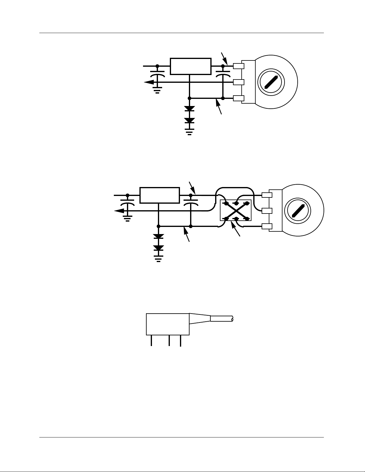
15 VDC supply
to Servo Controller Analog Input
(2) 1N4001 (typically) needed
on one input only. (These
provide the negative reference
voltage needed by the circuit.)
10 VDC
positive reference
10 volt
Regulator
negative reference
Potentiometer
(10KΩ typically)
If you need to reverse the direction of any of the potentiometer inputs, you can reverse the positions of the positive and negative references for that input potentiometer. A Double Throw, Double Pole
(DPDT) switch can be added if you will need to change it regularly:
15 VDC supply
to Servo Controller Analog Input
10 VDC
positive reference
10 volt
Regulator
Potentiometer
(10KΩ typically)
(2) 1N4001 (typically) needed
on one input only. (These
provide the negative reference
voltage needed by the circuit.)
negative reference
Back of DPDT switch
The pot must swing symmetrically around its middle point when this option is used.
The 16 servo motors are connected to the standard three pin sockets used by many brands of servo
motors. Some newer servo motors use a slightly different connector, and an adapter for this style of connector is available from the servo motor manufacturers. The pin out for these servo motor connections is
as follows:
SIGNAL
SERVO
+ SUPPLY
SERVO
- SUPPLY
The last remaining connector is for attaching the power supply which is used to power the servo motors. The power for these must come from an external source as they can potentially use a lot more current than the animation system can normally supply. Most servo motors run from a voltage between 3.5
volts and 7.5 volts. The lower the voltage the less strength and speed a given servo motor will have. A
higher voltage will give that same servo motor greater speed and strength.
3
Page 4

GILDERFLUKE & CO. ¥ 205 SOUTH FLOWER ST. ¥ BURBANK, CALIF. 91502-2102 ¥ 818/840-9484 ¥ FAX818/840-9485
5 5/16"
12345678 910111213141516
SERVO MOTOR OUTPUTS
SERVO MOTOR
POWER INPUT
STROKE ADJUSTMENTS
1 2 3 4 5 6 7 8 9 10 11 12 13 14 15 16
4"
RETRACT ADJUSTMENTS
1 2 3 4 5 6 7 8 9 10111213141516
J-6A INPUT
In some cases a lower speed is desired for the smoothness of the movement, while in other cases
the need for high speed or strength may be paramount. The chief disadvantages of running the servo
motors in high voltage / high speed applications are that the servo motor will run hotter and is much
more likely to have a mechanical failure.
The size of the servo motor, the load it is driving, and the amount of movement it is doing can all effect the amount of current it will require. Most of the smaller servo motors draw about an amp of current
at stall (This is when the servo motor shaft is held against the motor's best efforts to move it.). This condition isn't often encountered in any real world applications, but if you are planning on really abusing your
servo motors you should allow about an amp per motor when selecting a power supply. Under most normal conditions, 1/4 to 1/2 an amp per servo motor will be sufficient. If your power supply is undersized,
you will see a certain amount of interaction between servo motors when a number of them are moving
at the same time.
To reduce the number of wires needed to run into a servo motor-controlled figure it is not uncommon to run the high current power supply leads directly from the power supply to the servos in the figure
and gang the signal lines. When this is done, it is still necessary to run low current leads from the power
supply to the power supply connections on the Servo Motor Controller board. If the signal line runs to the
servo motors are long, it may be necessary to use shielded lines to prevent noise and cross-talk between
the servos. You can tell when you have this problem when some servo motors are tending to jitter uncontrollably.
Be aware that the servo motor input signals are notoriously bad travelers. They are susceptible to any
power supply noise, radio frequency (RF) interference, and even the noise from other servo motors. Try
to keep these lines as short as possible. Anything over 10 feet can cause problems. Even shorter lengths
can have problems under the right circumstances. Possible solutions include large capacitors across the
power supply leads and pullup resistors between the signal input and the positive supply line. These must
be located as close as possible to the servo motors.
Each channel of the Servo Motor Controller has two adjustments. The first sets the 'retracted' position
4
Page 5

GILDERFLUKE & CO. ¥ 205 SOUTH FLOWER ST. ¥ BURBANK, CALIF. 91502-2102 ¥ 818/840-9484 ¥ FAX818/840-9485
for the servo motor. The other sets the length of the 'stroke' away from the retract position, and therefore
the extended position. The retract position is always set before you try to set the 'extend' position.
Some caution must be used when adjusting servo motors or mechanical movements which may be
damaged by being commanded to go to a position beyond that which they are designed to move. In
these cases it is sometimes best to adjust both the retract and stroke trimpots to a center position for the
movement and then adjust them slowly outward from there.
The 16 Channel Servo Motor Controller comes in a plastic case which can be mounted by simply
double face taping it where ever you need. If you need to mount it more solidly, then put screws
through the back of the case as needed. The front of the case can be removed for service and adjustment after the box has been mounted.
The capabilities of the Servo Motor Controller outputs are as follows:
OUTPUT: OPEN COLLECTOR SWITCH TO GROUND
PULLUP: 4.7K PULLUP TO + SERVO POWER SUPPLY
OUTPUT CURRENT: 16 ma MAXIMUM
OUTPUT/SERVO VOLTAGE: 5 VDC NOMINAL / 36 VDC MAXIMUM
5
Page 6

GILDERFLUKE & CO. ¥ 205 SOUTH FLOWER ST. ¥ BURBANK, CALIF. 91502-2102 ¥ 818/840-9484 ¥ FAX818/840-9485
- JOYSTICK AMPLIFIER CONNECTIONS -
The inputs to the Joystick Amplifier is designed to be attached to up to 16 potentiometers. Typical
value for the pots is 10 Kohm. To ease the job of wiring to the pots, a 50 wire ribbon cable is used for the
input. Starting from the number one wire position, the first wire goes to one side of the pot, the next goes
to the middle (wiper) pole of the pot, and the third wire goes to the third connection of the pot. This then
repeats for the other 15 pots. The pin out for the connector is as follows:
PIN #1 BROWN Negative Reference #16
PIN #2 RED Joystick Amplifier Input #16
PIN #3 ORANGE Positive Reference #16
PIN #4 YELLOW Negative Reference #15
PIN #5 GREEN Joystick Amplifier Input #15
PIN #6 BLUE Positive Reference #15
PIN #7 VIOLET Negative Reference #14
PIN #8 GRAY Joystick Amplifier Input #14
PIN #9 WHITE Positive Reference #14
PIN #10 BLACK Negative Reference #13
PIN #11 BROWN Joystick Amplifier Input #13
PIN #12 RED Positive Reference #13
PIN #13 ORANGE Negative Reference #12
PIN #14 YELLOW Joystick Amplifier Input #12
PIN #15 GREEN Positive Reference #12
PIN #16 BLUE Negative Reference #11
PIN #17 VIOLET Joystick Amplifier Input #11
PIN #18 GRAY Positive Reference #11
PIN #19 WHITE Negative Reference #10
PIN #20 BLACK Joystick Amplifier Input #10
PIN #21 BROWN Positive Reference #10
PIN #22 RED Negative Reference #9
PIN #23 ORANGE Joystick Amplifier Input #9
PIN #24 YELLOW Positive Reference #9
PIN #25 GREEN Negative Reference #8
PIN #26 BLUE Joystick Amplifier Input #8
PIN #27 VIOLET Positive Reference #8
PIN #28 GRAY Negative Reference #7
PIN #29 WHITE Joystick Amplifier Input #7
PIN #30 BLACK Positive Reference #7
PIN #31 BROWN Negative Reference #6
PIN #32 RED Joystick Amplifier Input #6
PIN #33 ORANGE Positive Reference #6
PIN #34 YELLOW Negative Reference #5
PIN #35 GREEN Joystick Amplifier Input #5
PIN #36 BLUE Positive Reference #5
PIN #37 VIOLET Negative Reference #4
PIN #38 GRAY Joystick Amplifier Input #4
PIN #39 WHITE Positive Reference #4
6
Page 7

GILDERFLUKE & CO. ¥ 205 SOUTH FLOWER ST. ¥ BURBANK, CALIF. 91502-2102 ¥ 818/840-9484 ¥ FAX818/840-9485
PIN #40 BLACK Negative Reference #3
PIN #41 BROWN Joystick Amplifier Input #3
PIN #42 RED Positive Reference #3
PIN #43 ORANGE Negative Reference #2
PIN #44 YELLOW Joystick Amplifier Input #2
PIN #45 GREEN Positive Reference #2
PIN #46 BLUE Negative Reference #1
PIN #47 VIOLET Joystick Amplifier Input #1
PIN #48 GRAY Positive Reference #1
PIN #49 WHITE NO CONNECTION
PIN #50 BLACK NO CONNECTION
A typical connection for a pot is as follows:
Potentiometer
(10KΩ typically)
10 VDC positive reference
to Joystick Amplifier input
negative reference
If you need to reverse the direction of any of the potentiometer inputs, you can reverse the positions of the positive and negative references for that input potentiometer. A Double Throw, Double Pole
(DPDT) switch can be added if you will need to change it regularly:
Potentiometer
(10KΩ typically)
10 VDC positive reference
to Joystick Amplifier input
negative reference
Back of DPDT switch
The pot must swing symmetrically around its middle point when this option is used.
All of the positive and negative references fed to the pots are wired in parallel. If needed, a single
pair of wires may be used for the references to a number of different pots.
7
Page 8

GILDERFLUKE & CO. ¥ 205 SOUTH FLOWER ST. ¥ BURBANK, CALIF. 91502-2102 ¥ 818/840-9484 ¥ FAX818/840-9485
5 5/16"
J-6A OUTPUT
STROKE ADJUSTMENTS
1
3
5
7
9
11
13
15
2
4"
1
2
4
6
8
10
12
14
16
RETRACT ADJUSTMENTS
3
5
4
7
6
9
8
10
11
12
13
14
15
16
POT INPUTS
The output of the Joystick Amplifier is a standard J-6/A output. The pin out for this connection can be
found above in the Servo Motor Controller wiring instructions.
Each channel of the 16 Channel Joystick Amplifier has two adjustments. The first sets the output
level for the 'retract' end of the pot. This is where the Joystick Amp is usually adjusted for a 0 VDC output.
The second adjustment sets the 'stroke' length, and therefore the high level output for the channel. This
is normally adjusted to 10 VDC. These two adjustments interact somewhat, so each will need to be adjusted in turn until the desired output levels are achieved. When used with a 16 Channel Servo Motor
Controller, the adjustments on the Joystick Amplifier must be made first.
Power for the Joystick Amplifier comes from a small wall mount-style transformer attached to it. When
used with the 16 Channel Servo Motor Controller, this transformer supplies power for both units through
the Joystick Amp. A LED on the front of the Joystick Amp shows that it has power to it.
The 16 Channel Joystick Amplifier comes in a plastic case which can be mounted by simply double
face taping it where ever you need. If you need to mount it more solidly, then put screws through the
back of the case as needed. The front of the case can be removed for service and adjustment after the
box has been mounted.
The output capabilities of all Joystick Amplifiers are as follows:
OUTPUT VOLTAGE: 0 TO 10 VDC
OUTPUT CURRENT: 0 TO 24 ma
OUTPUT DEVICE: LM324
OUTPUT PROTECTION: OVERVOLTAGE/CURRENT PROTECTION
INHERENT TO LM324
8
 Loading...