

Page 1

Gilderfluke & Co.• 205 South Flower Street • Burbank, California 91502 • 818/840-9484 • 800/776-5972 • fax 818/840-9485
Sd-50/0, Sd-50/8, Sd-50/40
Audio & Show Control Systems
The Sd-50/0 is a complete, stand alone .Mp3/.wav player system. Just add a power supply and your
speakers, and it will play audio from the Sd/MMC flash card.
The Sd-50/8 & Sd-50/40 add up to forty digital Show Control outputs, DMX-512, MIDI in or Net Serial
RS-422 serial port input, DMX-512 output and scheduling to a Sd-50/0 player. The Sd-50/8 & Sd-50/40
are complete audio and Show Control solutions.
The Sd-50/GPS8 & Sd-50/GPS40 adds a GPS receiver for triggering by time or location. The Sd-50/
WWV8 & Sd-50/WWV40 adds WWV synchronized scheduling. This gives you ‘Atomic’ clock accuracy for
carillons, schools, churches, bell towers & industrial annunciator systems.
Sd-50/xx Manual / October 29, 2012 2:29 PM / page 1 of 120
Page 2

Gilderfluke & Co.• 205 South Flower Street • Burbank, California 91502 • 818/840-9484 • 800/776-5972 • fax 818/840-9485
Safety Disclaimer: Any electronic or mechanical sys-
tem has a potential to fail. Certain applications using
Gilderfluke & Company equipment may involve potential
risks of death, personal injury, or severe property, or en-
vironmental damage (“Critical Application”). Gilderfluke
& Company equipment is not designed, intended,
authorized, or warranted to be suitable in life support
applications, devices, or systems, or other critical appli-
cations. Inclusion of Gilderfluke & Company products in
such applications is understood to be fully at the risk of
the customer. In order to minimize risks associated with
the customer's applications, adequate design and oper-
ating safeguards should be provided by the customer to
minimize inherent or procedural hazards.
Gilderfluke & Company assumes no liability for appli-
cations assistance, customer produced design, software
performance, or infringement of patents or copyrights.
Nor does Gilderfluke & Company warrant or represent
that any license, either express, or implied, is granted
under any patent right, copyright, mask work right, or
other intellectual property right of Gilderfluke & Com-
pany covering or relating to any combination, machine,
or process in which Gilderfluke & Company products or
services might be or are used.
Sd-50/xx Manual / October 29, 2012 2:29 PM / page 2 of 120
Page 3

Gilderfluke & Co.• 205 South Flower Street • Burbank, California 91502 • 818/840-9484 • 800/776-5972 • fax 818/840-9485
......................................................................Getting Started (quickly)! 9
.............................................Sd-50/0, Sd-50/8 or Sd-50/40 Overview! 12
.......................................................................Features of the Sd-50/0 include:! 12
......................................Features the Sd-50/8 and Sd-50/40 adds includes...! 14
..................................................................Differences between Sd-50s and Mp3-50s! 17
.............................................Sd-50/0 Sd-50/8 or Sd-50/40 Indicators! 19
....................................................................Right (Sd-50/0, Sd-50/8, Sd-50/40)! 20
...........................................................Sd Access (Sd-50/0, Sd-50/8, Sd-50/40)! 20
...........................................................Audio Run (Sd-50/0, Sd-50/8, Sd-50/40)! 20
........................................................Board Error (Sd-50/0, Sd-50/8, Sd-50/40)! 20
..........................................................................Show Run (Sd-50/8, Sd-50/40)! 20
................................................................DMX/MIDI/Serial (Sd-50/8, Sd-50/40)! 20
....................................................................Heart (Sd-50/0, Sd-50/8, Sd-50/40)! 21
......................................................................Left (Sd-50/0, Sd-50/8, Sd-50/40)! 21
..............................................Fuses (1 LED on Sd-50/8, 5 LEDs on Sd-50/40)! 21
......................................J8 ʻAʼ, ʻBʼ, ʻCʼ, & ʻDʼ Input LEDs (Sd-50/8, Sd-50/40)! 21
..............................Output LEDs (8 LEDs on Sd-50/8, 40 LEDs on Sd-50/40)! 21
.........................................................................................Input Open (Sd-50/0)! 22
.........................................................................................Input Close (Sd-50/0)! 22
.......................................Sd-50/0, Sd-50/8 or Sd-50/40 Connections! 23
..............................................RS-232 Serial Port (Sd-50/0, Sd-50/8, Sd-50/40)! 24
..................................................Sd/MMC Socket (Sd-50/0, Sd-50/8, Sd-50/40)! 24
........................................................Optional Clock Input (Sd-50/8, Sd-50/40)! 25
......................................Card Cage Connection (Sd-50/0, Sd-50/8, Sd-50/40)! 26
.....................................................Power Supply (Sd-50/0, Sd-50/8, Sd-50/40)! 26
..............................................DMX-512/MIDI/Net Serial In (Sd-50/8, Sd-50/40)! 26
DMX-512 Input! 26
MIDI Notes Input! 27
Net Serial Input! 28
IR Input Mode! 29
IR MultiLingual Mode! 30
None! 32
................................................................DMX-512 Output (Sd-50/8, Sd-50/40)! 32
..........................................Left Speaker Output (Sd-50/0, Sd-50/8, Sd-50/40)! 33
........................................Right Speaker Output (Sd-50/0, Sd-50/8, Sd-50/40) ! 33
.................................................Left Line Output (Sd-50/0, Sd-50/8, Sd-50/40)! 33
..............................................Right Line Output (Sd-50/0, Sd-50/8, Sd-50/40) ! 33
........................................ʻ¼ J6ʼ Inputs/Outputs (Sd-50/0, Sd-50/8, Sd-50/40)! 33
Outputs via the ‘" J6’ port! 34
Inputs via the ‘" J6’ port! 35
ServoMotor PWM via the ‘" J6’ port! 35
................................................J8 ʻAʼ, ʻBʼ, ʻCʼ & ʻDʼ inputs (Sd-50/8, Sd-50/40)! 37
J8 ‘A’, ‘B’, ‘C’ & ‘D’ Binary:! 38
.............................................................ʻJ6ʼ Show Control Outputs (Sd-50/40)! 39
................................Defaults for Sd-50/0s, Sd-50/8s and Sd-50/40s! 43
Sd-50/0 (audio only) Defaults! 43
Sd-50/8 Defaults! 44
Sd-50/xx Manual / October 29, 2012 2:29 PM / page 3 of 120
Page 4

Gilderfluke & Co.• 205 South Flower Street • Burbank, California 91502 • 818/840-9484 • 800/776-5972 • fax 818/840-9485
Sd-50/40 Defaults! 45
Sd-50/WWV8 Defaults (w/ ‘atomic’ clock)! 45
Sd-50/WWV40 Defaults (w/ ‘atomic’ clock)! 45
...............................................What You Should And Shouldn’t See! 46
................................Shows Capacities for Sd-50/8s and Sd-50/40s! 48
..................................What To Do With A New Sd/MMC Flash Card! 51
...............................Preparing Animation Data for AutoDownloads! 53
..............................................................................Locking Your Data! 55
..............................Sd-50/0, Sd-50/8 or Sd-50/40 Serial Commands! 56
..............................................................................................Echo Commands:! 57
Echo On: “a” [nn] (card address)! 57
Echo Off: “b”! 57
................................................................Card Status: “i” [nn] (card address)! 57
........................................................Card Reset: “j5AA5” [nn] (card address)! 59
................................................................................................Start Commands! 59
Start Track: “t” [nn] (card address)! 59
Start Global: “u”! 59
................................................................................................Stop Commands! 60
Stop Track: “x” [nn] (card address)! 60
Stop Global: “y”! 60
...............................................................................................Loop Commands! 60
Loop Track: “!” [nn] (card address)! 60
Loop Global: ““”! 60
....................................................................................Stop at End Commands! 60
Stop at End Track: “%” [nn] (card address)! 60
Stop at End Global: “&”! 60
...................................................................................Select Show Commands! 60
Select Show Track: “)” [nn] (Card Address) [nn] (show#)! 60
Select Show Global: “*” [nn] (show#)! 60
.....................................................................Select & Play Sound Commands! 61
Select Sound Track: “^t” [nn] (Card Address) [nn] (sound#)! 61
Select Sound Global: “^u” [nn] (sound#)! 61
.........................Volume Command: “^v” [nn] (Card Address) [vv] (Volume)! 61
...................................................................................Show Pause Commands! 61
Pause Show: “<” [nn] (card address)! 61
Continue Show: “>” [nn] (card address)! 61
.................................................AutoDownload: “sA5A5” [nn] (card address)! 62
........................................................................................RealTime Update: “~”! 62
...........................................................................................Serial Command Summary! 63
...............................Sd-50/0, Sd-50/8 or Sd-50/40 Hardware Config.! 64
..........................................................................ʻ¼ J6ʼ Internal/External Power! 64
..........................................................................................RS-422/Optoisolated! 64
........................................................................................Right Volume Control! 64
...........................................................................................Left Volume Control! 64
..........................Sd-50/0, Sd-50/8 or Sd-50/40 Serial Configuration! 65
...........................................................................Entering Serial Configuration! 66
Sd-50/xx Manual / October 29, 2012 2:29 PM / page 4 of 120
Page 5

Gilderfluke & Co.• 205 South Flower Street • Burbank, California 91502 • 818/840-9484 • 800/776-5972 • fax 818/840-9485
......................................................................................................Play a Sound! 69
.........................................................................................................Stop Sound! 69
......................................................................................Daylight Savings Time! 70
.........................................................................................................Stop at End! 70
..............................................................................................................Set Time! 71
...........................................................................................................Show Info! 71
.......................................................................................................Loop a Show! 71
..........................................................................Display Config. from Sd/MMC! 72
..................................................................................................Reload Defaults! 72
........................................................................................................Play a Show! 72
..........................................................................................................Stop Show! 72
................................................................................Set ServoMotor Endpoints! 72
......................................................................................................Verify Shows! 74
......................................................................................................................Exit! 74
....................................................................................................Set Time Zone! 74
...................................................................................Secondary Configuration Menu! 75
....................................................................................................Serial Address! 75
.......................................................................................................MIDI channel! 76
......................................................................................................MIDI 1st Note! 76
........................................................................................MCU Control Channel! 76
..............................................................................................Left Level Control! 76
............................................................................................Right Level Control! 76
.................................................................First Show Control Output Channel! 76
.................................................................................First ServoMotor Channel! 76
...............................................................................................................eeFlag0! 77
......................................................................................................Play a Sound! 77
.........................................................................................................Stop Sound! 77
...............................................................................................................eeFlag1! 77
...............................................................................................................eeFlag2! 77
.........................................................................................................Stop at End! 77
...............................................................................................................eeFlag3! 78
...............................................................................................................eeFlag4! 78
...............................................................................................................eeFlag5! 78
...........................................................................................................Show Info! 78
.......................................................................................................Loop a Show! 78
..........................................................................Display Config. from Sd/MMC! 79
..................................................................................................Reload Defaults! 79
........................................................................................................Play a Show! 79
..........................................................................................................Stop Show! 79
......................................................................................................Verify Shows! 79
......................................................................................................................Exit! 79
....................................................................................................Set Time Zone! 79
..........................Sd-50/0, Sd-50/8 or Sd-50/40 Software Installation! 81
........................................................................................Software/Firmware Versions! 82
...............................................Updating Firmware on a Sd-50/0, Sd-50/8 or Sd-50/40! 83
.................................................................................‘Mp3 Config.exe’! 84
....................................................................................................................Track Setup! 86
..............................................................................................................Move Up! 86
Sd-50/xx Manual / October 29, 2012 2:29 PM / page 5 of 120
Page 6

Gilderfluke & Co.• 205 South Flower Street • Burbank, California 91502 • 818/840-9484 • 800/776-5972 • fax 818/840-9485
.........................................................................................................Move Down! 86
....................................................................Reload Track List From Directory! 86
.................................................................................................................At End! 86
Stop! 87
Play Next Higher Selection! 87
Play Random Selection! 87
Play Same Selection Again! 87
Play Specific SoundFile! 87
...................................................Can Step On Track with a new Play request! 87
..................................................................................Track to Play at PowerUp! 88
................................................................................................................PlayList Setup! 89
...................................................................................................................Audio Setup! 90
.............................................................................................Main Volume Level! 90
.............................................................................................................Half Mute! 90
.....................................................................................RealTime Level Control! 91
........................................................................................................EQ Settings! 91
.....................................................................................Enable Power Amplifier! 91
..........................................................................................................‘" J6’ Input Setup! 92
...................................................................................................Playback Level! 93
Do not change Playback Level! 94
Fade to Full In! 94
Fade to Zero In! 94
Fade to ‘Half Mute’ In! 94
.......................................................................................................Start Playing! 94
Whatever is Next! 95
Next Higher Show or SoundFile! 95
The Same Show or SoundFile Again! 95
A Random Show or SoundFile! 95
Specific Show or SoundFile! 95
.......................................................................................................Stop Playing! 95
Stop Now! 96
Stop at End! 96
...............................................................................................Pause or Resume! 96
..........................................................................Do not Start or Stop Anything! 96
............................................................Animation ‘Virtual’ Audio Trigger Input Setup! 97
...................................................................................................Playback Level! 98
Do not change Playback Level! 98
Fade to Full In! 98
Fade to Zero In! 99
Fade to ‘Half Mute’ In! 99
.......................................................................................................Start Playing! 99
Whatever is Next! 99
Next Higher SoundFile! 99
The Same SoundFile Again! 99
A Random SoundFile! 99
Specific SoundFile! 100
.....................................................................................................Stop Playing! 100
Stop Now! 100
Stop at End! 100
............................................................................................Pause or Resume! 100
Sd-50/xx Manual / October 29, 2012 2:29 PM / page 6 of 120
Page 7

Gilderfluke & Co.• 205 South Flower Street • Burbank, California 91502 • 818/840-9484 • 800/776-5972 • fax 818/840-9485
........................................................................Do not Start or Stop Anything! 100
.............................................................................................Animation Control Setup! 101
............................................................................DMX/MIDI/Serial Port Setup! 101
Disable Serial Reception! 101
Enable DMX-512 Reception! 101
Enable DMX-512 Checksums! 102
Enable MIDI Reception! 102
MIDI Notes Trigger Animation Playback! 102
MIDI Channel Number! 103
MIDI First Note Number! 103
Net Serial Mode! 103
IR Trigger Mode! 104
..................................................................................................Brick Address! 105
.....................................................................Repeater MPU Control Channel! 105
.................................................................................First Animation Channel! 105
......................................................................................................Flash Setup! 105
Enable Animation From Flash! 106
Disable Outputs When Stopped! 106
Write Protect Flash Memory! 106
............................................................................................................Schedule Setup! 107
Disable Schedule Starts on ‘D’/White Input! 110
Reset Clock on ‘RTC’ Input! 110
....................................Sd-50/0, Sd-50/8, and Sd-50/40 Installation! 111
.............................Battery Replacement on a Sd-50/8 or Sd-50/40! 112
...............................................Care & Feeding of an GPS Receiver! 113
..............................................Care & Feeding of an ‘Atomic’ Clock! 114
.....................................................C-50Trans Transition Connector! 116
...................................................................Sd-50/CC-10 Card Cage! 117
FCC and CE Compliance:! 119
EC DECLARATION OF CONFORMITY! 119
.....................................................HEXadecimal to Decimal to ASCII to Percentage! 120
Sd-50/xx Manual / October 29, 2012 2:29 PM / page 7 of 120
Page 8
Gilderfluke & Co.• 205 South Flower Street • Burbank, California 91502 • 818/840-9484 • 800/776-5972 • fax 818/840-9485
A note about this manual:
This manual covers the specifics of the Sd-50/0, Sd-
50/8, Sd-50/40. To program the Sd-50/0, Sd-50/8,
Sd-50/40 you will also want to refer to the PC•MACs
manual sections that cover the PC•MACs software.
The Sd-50/0, Sd-50/8, Sd-50/40 is typically pro-
grammed in ‘Software-only’ or ‘Hardwareless RealTime’
mode. If you are using the PC•MACs MACs-USB for
programming your Sd-50/0, Sd-50/8, Sd-50/40 through
the DMX-512 inputs, please refer to the PC•MACs ‘Unlim-
ited’ mode.
The full PC•MACs manual can be downloaded from our
web site at:
http://www.gilderfluke.com
Sd-50/xx Manual / October 29, 2012 2:29 PM / page 8 of 120
Page 9

Gilderfluke & Co.• 205 South Flower Street • Burbank, California 91502 • 818/840-9484 • 800/776-5972 • fax 818/840-9485
Getting Started (quickly)
The following instructions describe how to quickly set up a Sd-50/xx to run using the default settings.
The default settings can be used in most applications.
1)! Insert the Sd/MMC flash card into you computer, or a USB card adapter.
2)! Check that the card is formatted for ‘FAT32’. Reformat if needed. (What to do with a new
Sd/MMC Flash card)
3)! Drag and drop all of your SoundFiles into the card.
4)! Open the ‘Mp3 Config.exe’ program.
5)! It will probably tell you that there are no files in the directory. Do a ‘save as’ and point it at
the Sd/MMC flash card where your sounds reside. (No files in Directory Warning)
6)! Select the appropriate player type under the ‘Player Type’ pulldown.
7)! Select ‘Reset Everything to Defaults’ under the ‘Edit’ pulldown.
8)! On the ‘Track Setup’ tab, press the ‘Reload Track List From Player Directory’ button.
! If you are setting up an installation where the Sd-50/0 will simply be playing on power-up
(instead of being triggered), set the ‘Track to play at Startup’ and the chain of sounds
that will play after each SoundFile. You can set one file to play ‘whatever is next’ (or a
random track) at its end, and the ‘All’ button will apply this setting to all the SoundFiles.
All the sounds will then play round-robin (or randomly).
9)! If you are setting up a Sd-50/8 or Sd-50/40, make a note of the first sound in the list.
10)! On the ‘Audio Setup’ tab, disable the amplifier if you will not be using the onboard amplifier.
(Enable Power Amplifier)
11)! Save and quit the ‘Mp3 Config.exe’ program.
12)! Tell Windows to ‘Eject’ the Sd/MMC flash card and Move the Sd/MMC flash card to the Sd-
50. If you do not ‘Eject’ the Sd/MMC flash card properly, Windows may damage the files you
just put on the card.
If you just configured a Sd-50/0, it is now ready to run. Connect speakers and a power supply. If you
set a startup sound and chain of SoundFiles to play after, It will start playing when it is powered up. Otherwise, it will now accept inputs on the ‘" J6’ inputs to the player to trigger and play sounds. Depending
on the number of SoundFiles, the ‘Mp3 Config.exe’ program will have set the inputs to directly select the
SoundFiles, or use a binary pattern to select them. Some of the upper input bits may have been set to
stop, mute, unmute or half mute the audio.
If you are using a Sd-50/8 or Sd-50/40, you will also need to connect whatever you are controlling,
speakers and a power supply. You can then program a show to go along with your sound. The following
instructions cover setting up a show, but not the actual programming of the show. A primer on programming the show can be found in the PC•MACs manual. Connections for the Show Control outputs can be
Sd-50/xx Manual / October 29, 2012 2:29 PM / page 9 of 120
Page 10

Gilderfluke & Co.• 205 South Flower Street • Burbank, California 91502 • 818/840-9484 • 800/776-5972 • fax 818/840-9485
found elsewhere in this manual. If you just want to watch the LED indicators for the Show Control Outputs
on the Sd-50/8 or Sd-50/40 blink, you can skip connecting to your show for now.
1)! Open the ‘PC•MACs’ program.
2)! Select the ‘New’ command from under the ‘File’ pulldown.
3)! Set the length for your show.
4)! Select ‘Audio’ for your sync type.
5)! Press the ‘Load Media File’ button. Navigate to the first SoundFile from the ‘Tracks’ list in
the ‘Mp3 Config.exe’ program and select it (you were supposed to make a note of which
sound if ‘first’ in step #9 above).
6)! Set the ‘.Mp3/.wav player’ Offset to one second (00:00:01.00). This delays the start of the
sound to one second after the show starts.
7)! Popup the ‘Site File’ menu, and select ‘New’ from the top of the list. Give the new site file a
name. Click ‘OK’.
8)! Close the ‘Show Information’ dialog.
9)! Select the ‘Show List’ command from under the ‘Channels’ pulldown.
10)! Select the ‘Create Multiple’ command from under the ‘Channels’ pulldown. Select zero ana-
logs and eight digitals (Sd-50/8) or forty digitals (Sd-50/40). These are your ‘Show Control’
Outputs. Click ‘OK’.
11)! Select the ‘Create Figure...’ command from under the ‘Channels’ pulldown. Name the figure
‘Sound Triggers’. Click ‘OK’.
12)! Select the figure you just created so that it is highlighted. Now select the ‘Create Multiple’
command from under the ‘Channels’ pulldown again.
13)! Select the ‘Create Multiple’ command from under the ‘Channels’ pulldown. Select zero ana-
logs and eight digitals. These are your ‘Audio Trigger’ Outputs. Click ‘OK’.
14)Select the ‘Move to OffLine’ command from under the ‘OffLine’ pulldown. You will see a two
column dialog where all the channels you created are shown in the left column, and any
channels you are editing are shown in the right column. Select the ‘Sound Triggers’ figure
from the left column, and press the ‘>>>’ button to move the ‘Sound Triggers’ to the ‘Editing’
column. Click ‘OK’.
15)! The eight possible audio triggers are shown at the bottom of the window. Use the Right
mouse button to draw a line on the bottom most channel from one second to two seconds.
This will start your first SoundFile playing at one second after your show starts. Lines drawn
of different outputs will trigger different SoundFiles in other shows.
At this point you can program the rest of your show.
Sd-50/xx Manual / October 29, 2012 2:29 PM / page 10 of 120
Page 11

Gilderfluke & Co.• 205 South Flower Street • Burbank, California 91502 • 818/840-9484 • 800/776-5972 • fax 818/840-9485
If you have a PC•MACs RealTime license, you can assign the Show Control channels to the Soft Console and program that way.
Without a PC•MACs RealTime license, programming can be as simple as:
1)! Press the ‘Selected Channels’ button at the bottom middle of the OffLine Editing Window.
This opens the ‘Move to OffLine’ dialog we used before.
2)! Move the ‘Audio Triggers’ from the right ‘Editing’ column to the left ‘Not Editing’.
3)! Select all of the other Show Control channels you created and move them from the left ‘Not
Editing’ column to the right ‘Editing’ column. Click OK.
4)! Draw ‘lines’ all over the Show Control channels using the right mouse button.
Once completed, you save this and other shows to the Sd-50/8 or Sd-50/40 using the ‘Save as Auto-
Download…’ dialog under the ‘File’ pulldown. An ‘AutoDownload Quick Start’, as well as full instructions
on AutoDownloading shows is found in the PC•MACs manual.
If it is small, you can serially download your AutoDownload file to the Sd-50/8 or Sd-50/40. For larger
files, just save the AutoDownload file to your hard disk using the ‘Build Brick’ button on the ‘Save As
AutoDownload’ dialog (found under the ‘File’ pulldown). Then take the AutoDownload file that you created,
and drag and drop it onto your Sd/MMC flash card. Next time this card is inserted into your Sd-50/8 or Sd-
50/40, it will load your show into the onboard flash memory. If set to do so, the file will start playing. Otherwise, it will wait for a trigger input to tell it to start playing.
Sd-50/xx Manual / October 29, 2012 2:29 PM / page 11 of 120
Page 12

Gilderfluke & Co.• 205 South Flower Street • Burbank, California 91502 • 818/840-9484 • 800/776-5972 • fax 818/840-9485
Sd-50/0, Sd-50/8 or Sd-50/40 Overview
The Sd-50/xx family consists of three members:
The Sd-50/0 is a complete .Mp3/.wav player system. It uses a standard Sd/MMC flash card to hold
audio files stored in .mp3 or .wav formats. It includes an amazingly efficient 100 Watt Class-D stereo amplifier which has the output power of many 500 Watt linear amplifiers. With no moving parts to wear out,
the Sd-50/0 should well outlast the speakers it is attached to. The Sd-50/0 can be used singly, or in combination with additional Sd-50/xx’s, BR-SmartMedia cards or any Gilderfluke & Co. equipment. It can
provide the audio for animated shows and displays, fountains, fireworks, safety announcements, advertising, alarm systems, window displays special effects, signs, clocks and carillons, or anything else that
needs a sound to be played back.
Audio is loaded onto the Sd-50/0s by first converting it to an .mp3 or .wav format files. There are a
number of commercial, freeware and shareware programs for doing this. All audio editing programs now
include .mp3 encoders*. You can even use Apple’s iTunes!
SoundFiles are moved to the Sd-50’s by temporarily moving the Sd/MMC flash card to an appropriate
slot or reader attached to your computer. The Sd/MMC flash card will appear as a ‘removable disk drive’
on your computer. You can then ‘drag and drop’ your audio and show files onto to the Sd/MMC flash card.
This works identically when using either a Macintosh or Windows-based computer.
The Sd-50/8 and Sd-50/40 add Show Control features to the Sd-50/0s. The Sd-50/8s or Sd-50/40s
can be used singly, or in combination with additional Sd-50/xx’s, BR-SmartMedia cards or any
Gilderfluke & Co. equipment. It can be used to control animated shows and displays, fountains, fireworks,
lighting, sound systems, simulators, slide and movie projectors, fiber optics, window displays, motors,
pneumatic and hydraulic systems, neon special effects, signs, machines and machine tools in process
control, or anything else that can be controlled by an electrical signal.
The Show Control side of the Sd-50/8 or Sd-50/40 is programmed using our PC•MACs Show Control
software. While programming, data can be sent to the Sd-50/8 or Sd-50/40 through its DMX-512 input,
‘Net Serial’ RS-422 port, or RS-232 serial port. Once programed, data is sent to the Sd-50/8 or Sd-50/40
through the PC’s serial port or loaded onto the Sd/MMC flash card for permanent storage. The Sd-50/8 or
Sd-50/40 can then be disconnected from the PC and it will run all by itself.
When used with a ‘Hardwareless RealTime’ licensed copy of PC•MACs software, Sd-50/8s or Sd-50/
40s can have their outputs programmed and updated in real time with just a PC and a serial connection.
When used with the PC•MACs hardware (MACs-SMP or MACs-USB Smpte Card), up to sixty-four Sd-50/
8s or Sd-50/40s can be updated in RealTime through the DMX-512 port.
Features of the Sd-50/0 include:
Stand alone stereo playback of standard .mp3 and .wav audio files. The Sd-50s support all
•
standard .mp3 encoding rates, including ‘variable’. Sixteen bit .wav files with sample rates up
* Contact our sales staff for current .mp3/.wav file converter recommendations.
Sd-50/xx Manual / October 29, 2012 2:29 PM / page 12 of 120
Page 13

Gilderfluke & Co.• 205 South Flower Street • Burbank, California 91502 • 818/840-9484 • 800/776-5972 • fax 818/840-9485
to 48K per second are supported.
Amazingly powerful 100 Watt Stereo Class-D Amplifier (fifty watts/channel). This amplifier has
•
the output power of a typical 400 to 500 Watt linear amplifier, but without the high current
draw and waste heat. In most applications, this amplifier means that all you need to add are
appropriate speakers, a Sd/MMC flash card and a power supply to get up and running.
Up to 255 different SoundFiles can be selected and played.
•
Sound capacity is only limited by the size of the Sd/MMC flash card installed. As of this writ-
•
ing, Sd cards of up to four GBytes have been tested with the Sd-50/xxʼs. Using typical
.mp3 data rates, you can put about two full day’s worth of sound (yes, 48 hours!) on a single
four GByte Sd card. Larger capacity Sd cards are on the way, and should work just as well,
and hold even more sound.
Audio data is stored in standard Sd/MMC flash cards. You move the Sd/MMC flash card to
•
your computer for high speed ‘drag-n-drop’ downloading. Some computers have Sd/MMC
slots built in. Others will need to use a USB-to-Sd/MMC adapter. In either case, your Macintosh or Windows-based computer will mount the Sd/MMC flash card as a ‘removable Drive’.
You copy your sound and animation files to the Sd/MMC flash card by just drag-n-dropping it,
just as you would copy any file from one folder to another.
Two line level outputs (RCA Jacks) for attaching external amplifiers.
•
All configuration is done through a user friendly Windows-based ‘Mp3 Config.exe’ program.
•
You can set the volume, EQ, and what each of the trigger inputs does. Eight of the inputs are
from the outside world through optoisolators, The other eight inputs come directly from the
Show Control side of the Sd-50/8 or Sd-50/40, if these options are installed. Any of the
inputs can be used to ramp audio to preset levels, select and play specific SoundFiles or select SoundFiles from a preset list or randomizer. Shows can be selected directly by an input,
or using a binary pattern to allow access to all 255 different possible audio files.
Screwdriver-accessible volume controls. These make it easy to make final adjustments in the
•
output level of the Sd-50s. Additional ‘software’ volume controls set up through the ‘Mp3
Config.exe’ program allow you to set ‘limits’, so the volume can not be turned too high using
these pots.
Mounts stand alone, in 2-3/4” Augat Snap Track, or up to ten in a Sd-50/CC10 cage (Sd-50/
•
0 only). Using optional brackets, mounts on most flavors of DIN rails.
The Sd-50/xx will run from power supplies with output voltages between twelve to twenty-four
•
volts DC. The Sd-50/xxʼs can even be run from batteries! For maximum output with the
onboard amplifier, use twenty-four volts, and add approximately 100 Watts (for amplifier) plus
your loads when selecting your power supply. Both screw terminal and 2.1 mm power connections are available.
Sd-50/xx Manual / October 29, 2012 2:29 PM / page 13 of 120
Page 14

Gilderfluke & Co.• 205 South Flower Street • Burbank, California 91502 • 818/840-9484 • 800/776-5972 • fax 818/840-9485
Features the Sd-50/8 and Sd-50/40 adds includes...
Eight (Sd-50/8) or forty (Sd-50/40) digital (on/off) Show Control outputs to a Sd-50/0. These
•
can be used to drive solenoid valves, relays, LEDs and other typical loads directly.
DMX-512 input for programming or controlling the .Mp3/.wav player and show control outputs.
•
The Sd-50/8 or Sd-50/40 can be operated as a ‘slave’ following whatever DMX-512 data it
receives from the DMX-512 network.
DMX-512 output from onboard Show Control memory or when running from RealTime up-
•
dates through the RS-232 serial port. The Sd-50/8 or Sd-50/40 can be operated as a ‘master’,
sending DMX-512 to control other Sd-50/8s or Sd-50/40s, light dimmers, wiggle lights, strobe
lights, or any other DMX-512 controlled devices. The DMX-512 output is also an easy way to
add additional Show Control outputs to Sd-50/8s or Sd-50/40s.
Up to eight of the ‘" J6’ Show Control outputs can be used to control model airplane-style
•
PWM ServoMotor outputs.
Automatic ‘program in place’ download through the serial port on your PC or through the Sd/
•
MMC flash card. The amount of time it takes to download shows the Sd-50/8 or Sd-50/40 de-
pends on the length of the show(s) and the number of channels used. Short shows take only
seconds. Shows that fill the entire Sd-50/8s or Sd-50/40s memory will take longer to down-
load. It is much quicker to move the completed shows to the Sd/MMC flash card, and let the
Sd-50/8s or Sd-50/40s load them from there. Show audio and animation data can be distrib-
uted to clients by sending out preloaded Sd/MMC flash cards.
Four MBytes of nonvolatile Show Control memory. Using all forty Sd-50/40 Show Control out-
•
puts (and the audio control channel), this gives a show capacity of about six hour at thirty up-
dates per second! About eighteen hours for the Sd-50/8 using all eight of its outputs (and the
audio control channel)! Once downloaded, show data is retained for approximately forty
years, with or without power applied. Up to 255 individual shows can be loaded onto a Sd-50/
8 or Sd-50/40 at one time.
Battery-backed Real Time Clock. The Clock is factory trimmed for an accuracy of 50 parts per
•
million (PPM). Using the 365 day schedule, you can set when shows and sounds will be
played up to a year in advance. You can set it to play a specific schedule on a specific day, or
you can select a schedule by the day of the week. As an example, you can set a special
schedule to be used on the Fourth of July each year, or set a different schedule to be used
only on Sundays only through an entire month. In school and factory bell systems, different
schedules can be used on weekdays, and different schedules (or no schedule at all) for the
weekends. As long as the rules for the Gregorian calendar and leap years don’t change, the
Real Time Clock will be accurate until the year 10,000. The centuries will not automatically
advance, and will need to be adjusted manually each 100 years.
Optional radio controlled ‘Atomic’ clock can be used to accurately synchronize the clock in-
•
side the Sd-50/8 or Sd-50/40 to the national time standards broadcast over short wave radio
from Frankfurt, Germany; Colorado, USA; Rugby, England; Fukushima, East-Japan; and Ky-
Sd-50/xx Manual / October 29, 2012 2:29 PM / page 14 of 120
Page 15

Gilderfluke & Co.• 205 South Flower Street • Burbank, California 91502 • 818/840-9484 • 800/776-5972 • fax 818/840-9485
sushu, West-Japan. The ‘Atomic’ Clock synchronizes the clock inside the Sd-50/8 or Sd-50/
40 once each day. These radio signals are not available (or strong enough to be used) in all
parts of the world.
Optional GPS can be used to continuously synchronize the clock inside the Sd-50/8 or Sd-50/
•
40 to the world time standards broadcast from the GPS satellites orbiting over the earth. This
keeps the Sd-50/8 or Sd-50/40 synchronized to UTC (also known as ‘Zulu’ or ‘Greenwich
Mean Time’ (‘GMT’)) to within .001 of a second. Multiple Sd-50/8s and Sd-50/40s located
anywhere on Earth can be scheduled to play the same shows and sounds at the same times,
and will play them with .001 second accuracy. A more down-to-earth application would be to
synchronize the sounds and animation on a series of parade floats so that they all play with
perfect synchronization. The GPS receivers will work anywhere a clear view of the sky is
available. They are sealed to IP67 standards for mounting outdoors or in wet locations, and
come with a 25 foot cord to allow them to be mounted where they can receive the best GPS
signals.
AudioFiles can be selected, played and audio levels controlled from the Show Control Sys-
•
tem. Digital controls can be used to ramp levels between full, half and completely muted. The
rate of fades can be set up to 9.9 seconds. Left and Right audio outputs can also be assigned
to one or two analog channels, and the volume can be controlled individually, or assigned to
the same analog control channel and controlled together.
Two hundred fifty-five shows can be loaded onto a Sd-50/8 or Sd-50/40 at one time. Shows
•
can be accessed sequentially or directly using the four optoisolated ‘J8’ inputs or serial com-
mands sent through the RS-422 serial port. The ‘Next’ show can be set for the end of any
show, allowing you to loop a single show or build ‘chains’ of shows.
The Sd-50/8 or Sd-50/40 supports update rates from one frame per second to a maximum of
•
one hundred frames per second. Different shows can each be programmed at different frame
rates. This allows you to program ‘delay’ shows that tick along at a low frame rate between
your main shows, and use very little memory.
Four optoisolated ‘J8’ inputs to synchronize Sd-50/8s or Sd-50/40s with pushbuttons or other
•
real-time events. Multiple Sd-50/8s or Sd-50/40s can be triggered simultaneously or sequen-
tially. Each Sd-50/8 or Sd-50/40 input can be set to start, stop, pause, continue, or directly
select and play a specific show. Different actions can be requested on each inputs’ opening or
closing edges. If not used for anything else, the four optically isolated inputs can be used to
select and play up to fifteen shows at random through using a binary weighted pattern.
Shows can also be triggered via the RS-232 or RS-422 serial ports, MIDI in ‘notes’, or IR Trig-
•
ger Mode.
Each of the eight (Sd-50/8) or forty (Sd-50/40) Show Control outputs is rated for a continuous
•
load of 150 ma., or 500 ma. peak. This is enough to drive small solenoid valves, relays, LEDs
and similar loads. Relays can be used to control higher current or voltage loads (DRV-03, Pb-
DMX/08 through Pb-DMX/32, Pb-08 through Pb-32, LC-8SP, or SSR-FS). If more than forty
Sd-50/xx Manual / October 29, 2012 2:29 PM / page 15 of 120
Page 16

Gilderfluke & Co.• 205 South Flower Street • Burbank, California 91502 • 818/840-9484 • 800/776-5972 • fax 818/840-9485
outputs are needed, additional Sd-50/8s or Sd-50/40s can be added to give you as many
outputs as you need.
The digital Show Control outputs from a Sd-50/8 or Sd-50/40 can be fed to Digital to Analog
•
converters (like our single channel DAC-08 or four channel DAC-QUAD) wherever you need
0-10 volt analog control signals.
When programming, or when installed as a permanent part of a larger control system, the Sd-
•
50/8 or Sd-50/40 accepts data through its DMX-512 and RS-422 serial port. This data is used
to update the outputs, and takes precedence over the on board Flash memory.
Sd-50/xx Manual / October 29, 2012 2:29 PM / page 16 of 120
Page 17

Gilderfluke & Co.• 205 South Flower Street • Burbank, California 91502 • 818/840-9484 • 800/776-5972 • fax 818/840-9485
Differences between Sd-50s and Mp3-50s
Many first-time users of the Sd-50/xx will be familiar with our Mp3-50/0, Mp3-50/8 or Mp3-50/40. The
Mp3-50/xx series of Audio Repeaters and Show Controllers are the direct ancestors of the Sd-50/xx se-
ries. At first glance, it may be hard to tell the two of them apart. Their cases, mounting holes, and connectors are almost identical.
Some of the differences are:
The Mp3-50s used SmartMedia Flash cards for audio storage, which were the most com-
•
mon type of flash card available at the time the Mp3-50s were released. The Sd-50/xx
series use Sd/MMC flash cards. Sd flash cards are now the most common type of flash card
available. SmartMedia Flash cards topped out with capacities of 128 MBytes. Sd flash cards
are widely available with capacities to four and eight GBytes.
The Mp3-50 series required ‘blessing’ the flash card to load the firmware the player needed
•
to run before it could be used. No ‘blessing’ is needed with the Sd-50/xx series.
The Mp3-50 series required drivers be loaded on your computer before it would work with
•
them. The Sd-50s need no drivers.
The Mp3-50 series featured a USB port to download sounds and configurations to the
•
SmartMedia card. This was also the only way to ‘bless’ a flash card before use. The Sd-50s
eliminate the USB port and ‘blessing’ altogether. Cards are loaded with sounds and configured by moving them to a computer with a suitable Sd/MMC slot or adapter.
The Mp3-50 series limited the number of DMX-512 output channels to sixteen. No such limi-
•
tation exists on the Sd-50s.
DMX-512 is output on the Sd-50s, no matter what mode is selected for the DMX-512/MIDI
•
serial input. On the Mp3-50s, the output port always followed what was set on the input
port.
The Mp3-50s could not use the ‘" J6’ port for triggering animation. The Sd-50s can. You
•
can select shows directly using these eight inputs, or use a binary pattern to directly select
any of 255 different shows.
The Sd-50/8 or Sd-50/40 will allow you to take over pins used on the ‘" J6’ port for con-
•
trolling up to eight model airplane-style PWM ServoMotors.
The amplifier used on the Sd-50/xx series is rated for 100 Watts of class-D power, which is
•
equivalent to many 500 Watt linear amplifiers. The amplifier on the Mp3-50s was rated for
22 Watts stereo, or 11 watts per side.
The inputs and outputs on the Sd-50/xx series are better protected against transients.
•
Onboard flash memory is eight times larger on the Sd-50/xx series than the Mp3-50 se-
•
ries.
The RTC was installed on Mp3-50s only with the ‘Atomic’ Clock option. The Sd-50/8 or Sd-
•
50/40 come with the Real Time Clock chip installed, so the 365 day scheduling of sounds
Sd-50/xx Manual / October 29, 2012 2:29 PM / page 17 of 120
Page 18

Gilderfluke & Co.• 205 South Flower Street • Burbank, California 91502 • 818/840-9484 • 800/776-5972 • fax 818/840-9485
and shows can be used, albeit with less accuracy than is available with either the GPS or
‘Atomic’ clock options.
Schedules can now be ‘named’, and the names are retained for display on the serial menus
•
and for further editing.
Firmware upgrades only need the appropriate file be loaded onto an Sd flash card. On the
•
next boot, the player will check to see whether the firmware is more up-to-date than it already
has, and load it if it is.
Show, schedule and GPS files are loaded at boot-up only if they are different (different name,
•
date or time)from the files that are already loaded into the Sd-50. This means that there is
only a delay on boot-up if you have changed to a different flash card with a different show,
schedule or GPS files on it.
Real time updates on serial port menus. Shows sounds and shows playing, input status,
•
schedules being used, and names of the shows and sounds that are started from the RTC
schedules.
Sd-50/xx Manual / October 29, 2012 2:29 PM / page 18 of 120
Page 19
6.000
2.750
2.250
5.500
Gilderfluke & Company • Burbank, California
1.300
Sd/MMC Flash Card
Power
12–24 vdc
Speaker s
(4! to 8!)
Left Right
Sd-50/0
Gilderfluke & Company • Burbank, California
Error
Heart
Input Close
Input Open
Sd Acc ess
Audio Run
Right
serial
Left
RS-232
1
23
41213
7
8
6.000
2.750
2.250
5.500
Gilderfluke & Company • Burbank, California
1.300
Sd/MMC Flash Card
'A'
'B'
'C'
'D'
Fuse
7
6
5
4
3
2
1
0
0
0
Power
12–24 vdc
DMX/MIDI/
RS-422
In Out
Speaker s
(4! to 8!)
Left Right
Sd-50/8
Error
Heart
Show Run
DMX-512/
MIDI/Serial
Sd Acc ess
Audio Run
Right
serial
Left
Opti on al
Clo ck
Inp ut
RS-232
1
23
45
11
10
9
67
8
6.000
2.750
2.250
5.500
Gilderfluke & Company • Burbank, California
1.300
Sd/MMC Flash Card
Error
Heart
Show Run
DMX-512/
MIDI/Serial
Sd Acc ess
Audio Run
Right
serial
Left
Opti on al
Clo ck
Inp ut
RS-232
'A'
'B'
'C'
'D'
3
7
6
5
4
2
1
0
Fuse
7
6
5
4
3
2
1
0
Fuse
Fuse
3 2 1 0
3 2 1 0
7
6
5
4
3
2
1
0
4
4
Power
12–24 vdc
DMX/MIDI/
RS-422
In Out
Speaker s
(4! to 8!)
Left Right
Sd-50/40Sd-50/40
1
23
45
11
10
9
67
8
Gilderfluke & Co.• 205 South Flower Street • Burbank, California 91502 • 818/840-9484 • 800/776-5972 • fax 818/840-9485
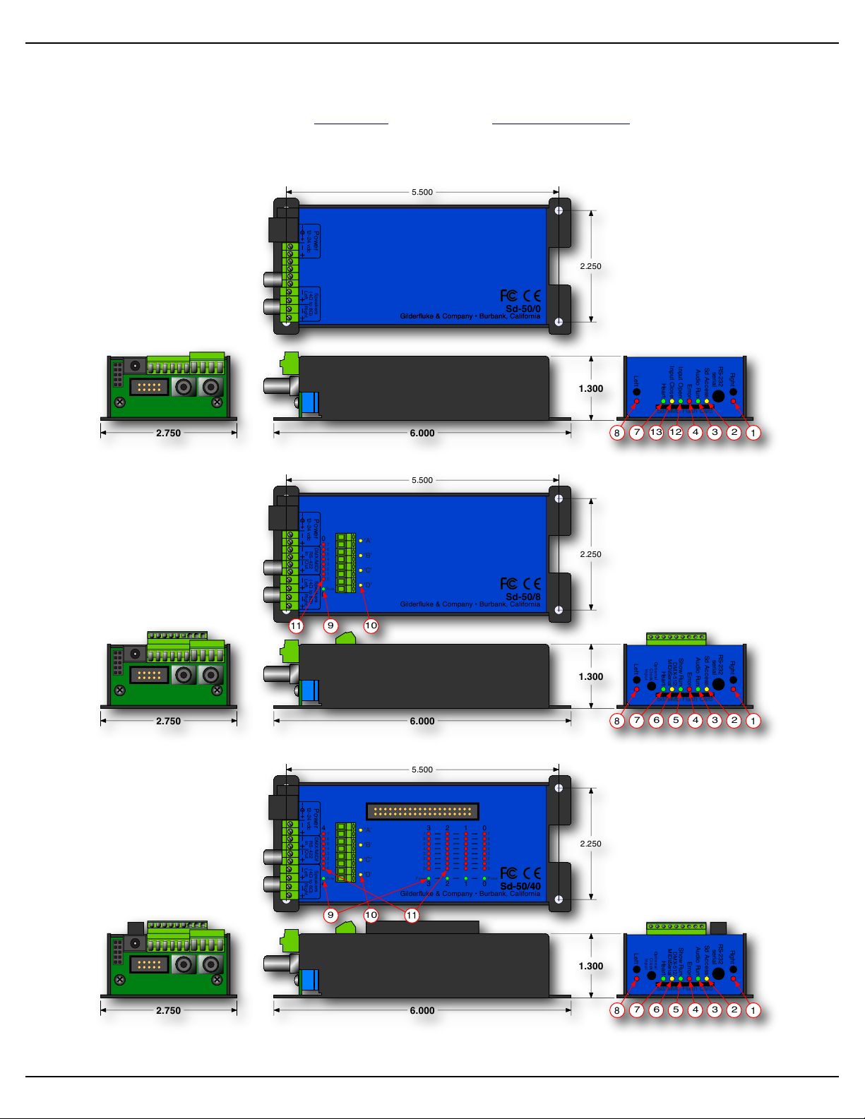
Sd-50/0 Sd-50/8 or Sd-50/40 Indicators
There are only a small number of connections, indicators, and configuration switches on each Sd-50/0, Sd-50/
8, Sd-50/40.
Sd-50/0 (Audio Only):
Sd-50/8 (Audio & Eight Show Control Outputs):
Sd-50/40 (Audio & Forty Show Control Outputs):
There are up to fifty-seven Status LEDs on the Sd-50/xx:
Sd-50/xx Manual / October 29, 2012 2:29 PM / page 19 of 120
Page 20

Gilderfluke & Co.• 205 South Flower Street • Burbank, California 91502 • 818/840-9484 • 800/776-5972 • fax 818/840-9485
1) ! Right (Sd-50/0, Sd-50/8, Sd-50/40)
! ! This LED flickers to give you a rough approximation of the audio being played out of the right side of
the audio player. It is downstream of the volume processing done on the Sd-50/0, and will dim to reflect
changes in volume level. It is upstream of the Right Volume Control Pot. Changes in the Right Volume
Control Pot will not affect the output level of this LED.
2) ! Sd Access (Sd-50/0, Sd-50/8, Sd-50/40)
!!This LED glows to show accesses to the Sd-card. Even when idle, this led will be flickering slightly as
the audio processor makes sure its friend, the Sd card hasn’t left it stranded.
3) ! Audio Run (Sd-50/0, Sd-50/8, Sd-50/40)
!!This LED will light to show that the Audio Player is currently playing back an .mp3 or .wav audio file.
4) ! Board Error (Sd-50/0, Sd-50/8, Sd-50/40)
!!This LED will flash to show you that the Sd-50/8 or Sd-50/40 has sensed one of the following errors:
a)! RealTime DMX-512 Update Error: The optional checksum in the DMX-512 RealTime update
didn’t agree with the data received.
b)! RealTime Serial Update Error: The checksum in the serial RealTime update didn’t agree with the
data received.
c)! Download Error: There was an error in the data being downloaded to the Sd-50/8 or Sd-50/40.
d)! Download Timeout: If the data being downloaded to the Sd-50/8 or Sd-50/40 stops midstream,
this LED will flash as the Sd-50/8 or Sd-50/40 returns itself to normal operating mode.
e)! Data Verification Failure: If you ask the Sd-50/8 or Sd-50/40 to verify the data in its flash mem-
ory, and it finds an error, it will flash this LED as well as displaying an error message on your computer screen.
f)! Memory locked: If you try to clear the flash memory or send a show to the Sd-50/8 or Sd-50/40
while the Write Protect is in the ‘locked’ position.
5) ! Show Run (Sd-50/8, Sd-50/40)
!!This LED will light to show that the Show Control half of the Sd-50/8 or Sd-50/40 is currently running a
preprogrammed show. This LED will also flash at half of the frame rate (usually 15 Hz) when the Sd-50/8 or
Sd-50/40 is receiving RealTime update data either through the DMX-512 or serial ports. During flash memory downloads, this LED will alternate on each 256 bytes of data received. At the normal 9600 baud serial
rate, this is about one Hz. This LED flashes at about the same rate when loading files from the Sd/MMC,
even though the data is being loaded much more quickly.
6) ! DMX/MIDI/Serial (Sd-50/8, Sd-50/40)
! ! This LED will light to show that the Sd-50/8 or Sd-50/40 is receiving RealTime Update data through the
DMX-512, MIDI, RS-232 or RS-422 serial ports. If the Sd-50/8 or Sd-50/40 is receiving show starts from
MIDI input, then this led will flash for about 1/10th of a second each time a ‘start’ happens. During flash
memory downloads, this LED will flash alternately with the Show Control Heart LED at twice the normal
heartbeat rate.
Sd-50/xx Manual / October 29, 2012 2:29 PM / page 20 of 120
Page 21

Gilderfluke & Co.• 205 South Flower Street • Burbank, California 91502 • 818/840-9484 • 800/776-5972 • fax 818/840-9485
7) ! Heart (Sd-50/0, Sd-50/8, Sd-50/40)
!!The ‘heartbeat’ will always flash so that you can see that the Sd-50/xx is alive. If this LED doesn’t flash
at least twice per second, you should power down the Sd-50/xx and check the power supply and connections to the Sd-50/xx. During flash memory downloads, this LED will flash alternately with the DMX/MIDI/
Serial LED at twice the normal heartbeat rate. During firmware upgrades, these two really go pitter-pat.
8) ! Left (Sd-50/0, Sd-50/8, Sd-50/40)
! ! This LED flickers to give you a rough approximation of the audio being played out of the left side of the
audio player. It is downstream of the volume processing done on the Sd-50/0, and will dim to reflect
changes in volume level. It is upstream of the Left Volume Control Pot. Changes in the Left Volume Control
Pot will not affect the output level of this LED.
9) ! Fuses (1 LED on Sd-50/8, 5 LEDs on Sd-50/40)
! ! The eight inputs of a Sd-50/0 and the eight outputs of the Sd-50/8 or Sd-50/40 make one, eight-bit
wide ‘channel’. The forty outputs of the Sd-50/8 or Sd-50/40 are divided into five, eight-bit wide ‘channels’.
! ! The eight inputs of a Sd-50/0, eight outputs of a Sd-50/8, and last channel of a Sd-50/40 are shared
with the eight optically isolated inputs to the audio half of the Sd-50/8 or Sd-50/40. This channel, and only
this channel can be switched between using ‘internal’ and ‘external’ power using the switch on the bottom
of the unit. This will be lit when there is an external voltage source present between pins #1 and #10 of the
‘" J6’ input, when the switch is in the ‘external’ position. If the fuse LED is off for this channel, check to
confirm that this switch is not in the ‘external’ position if you are not feeding this channel an external voltage
source.
! ! Each channel is fused for approximately one Amp of continuous current. These LEDs light to show if
the fuses are OK. If any are out, then a short circuit (or too heavy of a load) is dragging the outputs down
and causing the fuse to open. The fuses are actually ‘Polyswitch fuses’, which act more like circuit breakers. Once the overload is removed, they reset.
10)! J8 ʻAʼ, ʻBʼ, ʻCʼ, & ʻDʼ Input LEDs (Sd-50/8, Sd-50/40)
!!These four LED will light to show current is flowing through the four ‘J8’ Show Control Trigger inputs.
These LEDs are on the output side of the optoisolators, so if they are glowing, the microcontroller in the unit
should be seeing the signal. These four trigger inputs are the only way to use a switch closure input to start
the animated sequence playing on a Sd-50/8 or Sd-50/40. If not using the GPS, these LEDs will flash
slightly as the clock chip in the Sd-50/8 or Sd-50/40 is read.
11)! Output LEDs (8 LEDs on Sd-50/8, 40 LEDs on Sd-50/40)
! ! These LEDs show the current status of the Show Control digital outputs. If a LED is lit, then that output
is ‘ON’. Because the outputs of a Sd-50/8 or Sd-50/40 are ‘Open Collector, Switch To Ground’, you can
ground out any output pin, and the appropriate LED will light. This can be useful when diagnosing output
wiring problems. If you are commanding ‘on’ an output and you don’t see a LED, then the output is probably drawing too much current and the output is ‘self protecting’. Disconnect the load and see whether the
LED now lights. If it does, then it definitely is an overload problem. If it does not, then try turning ‘on’ some
of the other outputs. If they light OK, then the output driver might be damaged. If they do not, then verify
your addressing and retest.
Sd-50/xx Manual / October 29, 2012 2:29 PM / page 21 of 120
Page 22

Gilderfluke & Co.• 205 South Flower Street • Burbank, California 91502 • 818/840-9484 • 800/776-5972 • fax 818/840-9485
! ! If any of the pins on the ‘" J6’ output from a Sd-50/8 or Sd-50/40 are being used a ServoMotor PWM
outputs, the corresponding output LEDs will have a steady glow.
!!A Sd-50/0 has eight optically isolated trigger inputs which can be used to select, start shows and
SoundFiles and change the audio levels of the audio half of the Sd-50/0 player. The only output channel on
a Sd-50/8, and the last output channel on a Sd-50/40 are shared with these audio trigger inputs. Normally
these are not used to trigger the audio on a Sd-50/8 or Sd-50/40. The ‘virtual’ MPU trigger inputs from the
Show Control half of the Sd-50/8 or Sd-50/40 are normally used instead. This leaves these eight outputs
free to be used as outputs on most Sd-50/8 and Sd-50/40 applications.
12)! Input Open (Sd-50/0)
!!This LED flashes briefly to show that an opening edge has occurred on any of the eight ‘" J6’ inputs.
13)! Input Close (Sd-50/0)
!!This LED flashes briefly to show that a closing edge has occurred on any of the eight ‘" J6’ inputs.
Sd-50/xx Manual / October 29, 2012 2:29 PM / page 22 of 120
Page 23
6.000
2.750
2.250
5.500
Gilderfluke & Company • Burbank, California
1.300
Sd/MMC Flash Card
Power
12–24 vdc
Speake rs
(4! to 8!)
Left Right
Sd-50/0
Gilderfluke & Company • Burbank, California
Error
Heart
Input Close
Input Open
Sd Acc ess
Audio Run
Right
serial
Left
RS-232
AB
E
H
I
L
J
K
D
6.000
2.750
2.250
5.500
Gilderfluke & Company • Burbank, California
1.300
Sd/MMC Flash Card
'A'
'B'
'C'
'D'
Fuse
7
6
5
4
3
2
1
0
0
0
Power
12–24 vdc
DMX/MIDI/
RS-422
In Out
Speake rs
(4! to 8!)
Left Right
Sd-50/8
Error
Heart
Show Run
DMX-512/
MIDI/Serial
Sd Acc ess
Audio Run
Right
serial
Left
Opt ion al
Cl ock
Inp ut
RS-232
AB
M
C
E
F
G
H
I
L
J
K
D
6.000
2.750
2.250
5.500
Gilderfluke & Company • Burbank, California
1.300
Sd/MMC Flash Card
Error
Heart
Show Run
DMX-512/
MIDI/Serial
Sd Acc ess
Audio Run
Right
serial
Left
Opt ion al
Cl ock
Inp ut
RS-232
'A'
'B'
'C'
'D'
3
7
6
5
4
2
1
0
Fuse
7
6
5
4
3
2
1
0
Fuse
Fuse
3 2 1 0
3 2 1 0
7
6
5
4
3
2
1
0
4
4
Power
12–24 vdc
DMX/MIDI/
RS-422
In Out
Speake rs
(4! to 8!)
Left Right
Sd-50/40Sd-50/40
AB
NM
E
F
G
H
I
L
J
K
D
C
Gilderfluke & Co.• 205 South Flower Street • Burbank, California 91502 • 818/840-9484 • 800/776-5972 • fax 818/840-9485
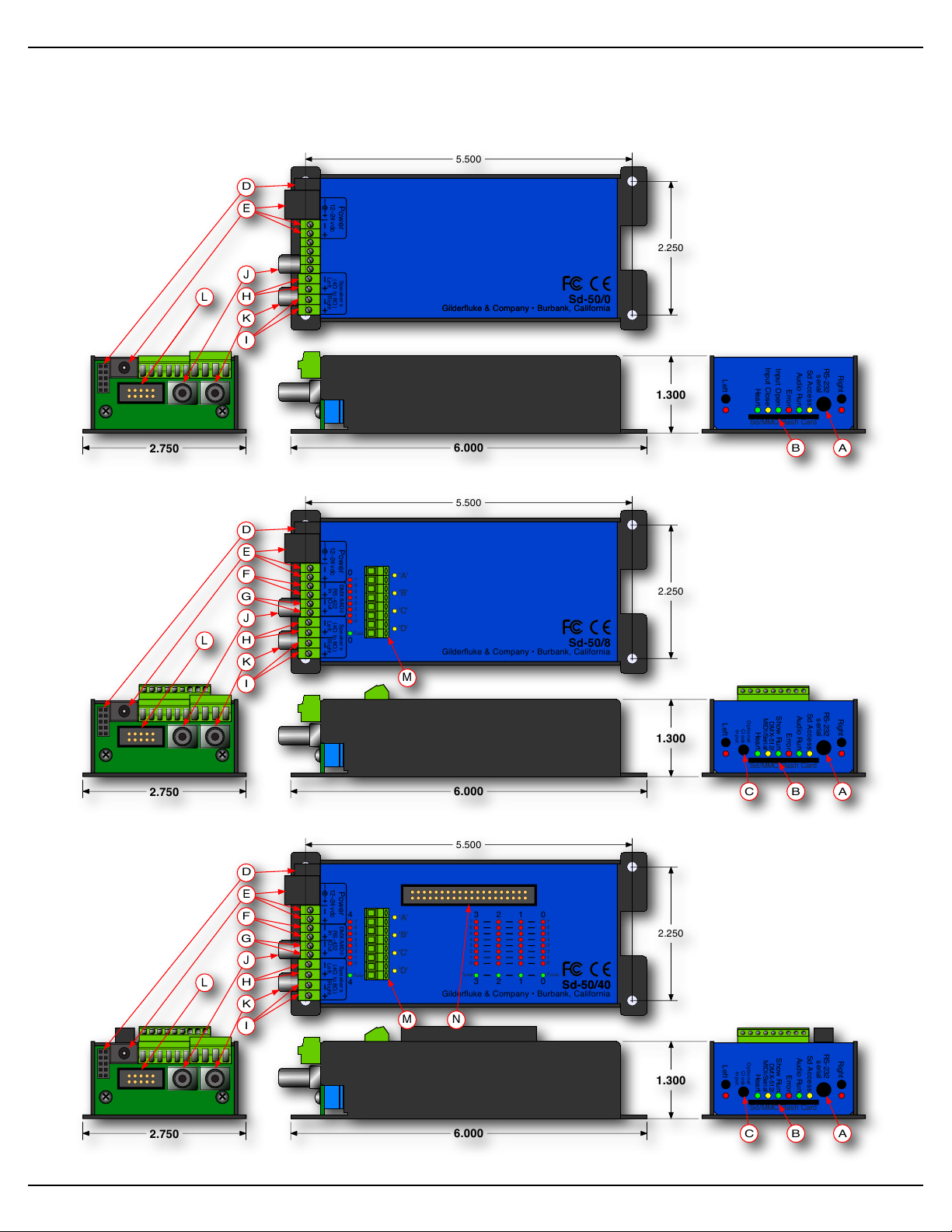
Sd-50/0, Sd-50/8 or Sd-50/40 Connections
Sd-50/0 (Audio Only):
Sd-50/8 (Audio & Eight Show Control Outputs):
Sd-50/40 (Audio & Forty Show Control Outputs):
Sd-50/xx Manual / October 29, 2012 2:29 PM / page 23 of 120
Page 24
Rxd
Txd
gnd
IBM AT
Serial
1
2
3
4
5
6
7
8
9
1
3
2(ring)
(tip)
(sleeve)
Gilderfluke & Co.• 205 South Flower Street • Burbank, California 91502 • 818/840-9484 • 800/776-5972 • fax 818/840-9485
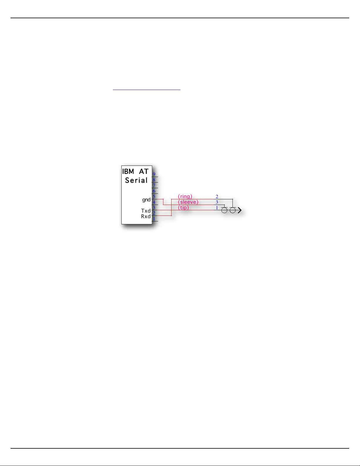
A) ! RS-232 Serial Port (Sd-50/0, Sd-50/8, Sd-50/40)
! ! The serial command set is identical to, and compatible with all the RS-422 Serial Ports used on
Gilderfluke & Company products. One difference between the Sd-50/xx and most of our products is that
the serial port is the primary method used to configure it. A Sd-50/xx is normally configured through the
‘Mp3 Config.exe’ program. This configuration is downloaded to the Sd-50/xx each time the Sd-50/xx
is turned on, but only if there is a difference between what was already on it.
! ! The Sd-50/xx has a serial ‘configuration’ mode which will allow you to check and modify the status
and configuration of the Show Control half of the Sd-50/xx. This is used to configure the animation half of
a Sd-50/xx if the audio half is not yet, or never is going to be used.
! ! If a Sd/MMC flash card is inserted into the Sd-50/xx which has been configured using the ‘Mp3
Config.exe’ program, any changes you have made to the configuration through the serial port will be over-
ridden by what is on the Sd/MMC flash card.
! ! The serial data signals from the Sd-50/xxʼs are brought out on a 1/8” three conductor ‘stereo’ socket.
Its pin out and cross connect to the standard serial port on a PC is as follows:
! ! The mnemonic for remembering the connections are: Ring = Receive, and Tip = Transmit.
! ! The Sd-50/xx expects to see the serial data in the following format:
ONE START BIT
EIGHT DATA BITS
ONE STOP BIT
B) ! Sd/MMC Socket (Sd-50/0, Sd-50/8, Sd-50/40)
!!This is where you plug in the flash card that is used to store the sound that is played back by the Sd-
50/xx.
! ! MMC (short for MultiMedia Card) was the original standard for flash cards of the size and shape used
in the Sd-50/xx. MMC flash cards have largely disappeared, replaced by the newer standard called Secure Digital (Sd). Sd flash cards are slightly thicker than MMC cards, have a ‘write protect’ switch on them,
and a few more pins than a MMC card.
! ! In addition to .mp3 and .wav SoundFiles, the Sd/MMC flash card usually contains the ‘Mp3 Config.exe’
program, the configuration files it creates (Sd-50.cfg, mp3-50.cfg, schedule.sch, etc.). Although not
needed by the Sd-50/xx, it is not unusual to store ‘back up’ copies of your shows and support files for
safe keeping. In this way, if you have to return to a job site years in the future, you will have the shows and
files needed to recreate and reprogram the installation.
Sd-50/xx Manual / October 29, 2012 2:29 PM / page 24 of 120
Page 25

Gilderfluke & Co.• 205 South Flower Street • Burbank, California 91502 • 818/840-9484 • 800/776-5972 • fax 818/840-9485
C) ! Optional Clock Input (Sd-50/8, Sd-50/40)
!!This 2.5 mm stereo jack is used to connect either the radio controlled ‘Atomic’ clock or the GPS re-
ceiver to the Sd-50/8 or Sd-50/40. This input is optically isolated. A ‘Polyswitch fuse’ protected twenty-four
vdc from this jack is used to power the ‘atomic’ clock or GPS receiver.
! ! All of the Sd-50/8s or Sd-50/40s are made with the built in Real TIme Clock. This allows you to sched-
ule when sounds and shows will play using a 365 day schedule. Without the additional accuracy provided
by the ‘Atomic’ or GPS clock, the built in RTC has an accuracy which has been laser trimmed for +/- 50
Parts Per Million (PPM). This is about the same as most modern electronic watches. Variations in temperature will cause a certain amount of variation in the accuracy of the RTC.
! ! An external clock can be used with the Sd-50/8 or Sd-50/40 to assure that the internal clock is always
insanely accurate. Either external clock option is locked to the atomic clocks that are used as the worldwide
time standards. The GPS uses the atomic clocks that are in a set of satellites orbiting the Earth. The ‘radio
controlled ‘Atomic’ clocks lock to radio signals broadcast from Frankfurt, Germany; Colorado, USA; Rugby,
England; Fukushima, East-Japan; and Kysushu, West-Japan.
! ! The GPS option will work anywhere on the planet. The receiver is mounted where where it has a view
of the sky. The GPS receivers are IPx7 rated for outdoor use, and are ‘bulkhead’ mounted using a single 5/
8” diameter hole. The fifteen foot long cable from the GPS receiver plugs into a small GPS power module
via a six pin mini-DIN connector. A three conductor cable with 2.5 mm stereo plugs at both ends is then
connected between the power module and the Sd-50/8 or Sd-50/40. The input to the Sd-50/8 or Sd-50/40
is optically isolated. You can stretch these wires for hundreds of feet, if needed.
! ! The GPS, once it acquires a lock on the satellites orbiting overhead, takes over for the on-board Real
Time Clock inside the Sd-50/8 or Sd-50/40. Every 60 seconds, on the half minute, the GPS clock sets the
RTC chip inside the Sd-50/8 or Sd-50/40. This assures you that even if the GPS loses lock, the internal
clock has been set accurately.
! ! The ‘Atomic’ Clock option can be used anywhere radio signals broadcast from Frankfurt, Germany;
Colorado, USA; Rugby, England; Fukushima, East-Japan; and Kysushu, West-Japan can be received.
! ! The ‘RTC input’ is used to resynchronize the internal Real Time Clock chip with the external ‘Atomic’
Clock once every 24 hours. The time which has been entered in the ‘Mp3 Config.exe’ must agree with the
time set for the alarm on the ‘Atomic’ Clock module.
! ! We are using 3:05:00 as the default resynchronization time. The external ‘Atomic’ Clock MUST be set
so that the alarm goes off at 03:05:00. It is at 3:05 AM so that when daylight savings starts and ends, there
will be no more than one hour before the Sd-50/8 or Sd-50/40 is resynchronized to the appropriate time.
Any earlier, and the daylight savings transition might be missed until the next resynchronization time.
! ! A single three conductor cable connects the ‘Atomic’ Clock module to the Sd-50/8 or Sd-50/40. 2.5
mm plugs are used to connect one end of the cable to the ‘Atomic’ Clock module, and the other end to the
‘Optional Clock Input’ jack on the Sd-50/8 or Sd-50/40. The input to the Sd-50/8 or Sd-50/40 is optically
isolated. You can stretch these wires for hundreds of feet, if needed.
! ! The link between the ‘Atomic’ Clock module and the Sd-50/8 or Sd-50/40 can be tested by pressing
the ‘snooze’ button atop the ‘Atomic’ Clock. This will light the back light on the LCD display. This will also
set the RTC inside the Sd-50/8 or Sd-50/40 to the completely WRONG time, if the connection is working.
You must manually set the time within the Sd-50/8 or Sd-50/40 after testing it in this way. If you don’t want
this to happen when testing this connection, power down the Sd-50/8 or Sd-50/40 before doing this test.
Power the Sd-50/8 or Sd-50/40 back up when you are finished testing.
Sd-50/xx Manual / October 29, 2012 2:29 PM / page 25 of 120
Page 26

Gilderfluke & Co.• 205 South Flower Street • Burbank, California 91502 • 818/840-9484 • 800/776-5972 • fax 818/840-9485
! ! To permanently prevent such accidental clock 'miss' settings after the ‘Atomic’ Clock is installed, you
can open the battery compartment and cut the wire which runs through it. This will disable the ‘snooze’ button, and thereby prevent it being hit accidentally in the future.
D) ! Card Cage Connection (Sd-50/0, Sd-50/8, Sd-50/40)
!!This female header connection is used to connect the power and secondary serial port to a Sd-50/CC-
10. It is not used for any other purpose.
E) ! Power Supply (Sd-50/0, Sd-50/8, Sd-50/40)
!!The power supply connections to the Sd-50/xx are available on both a 2.1 mm power jack and two of
the screw terminal positions. For mobile, permanent or higher current applications, you may wish to use the
screw terminals instead of the 2.1 mm power jack. It is less prone to being accidentally unplugged or vibrating loose. The screw terminals are also a very convenient place to ‘steal’ a little ‘juice’ to power the four
optically isolated inputs.
! ! If you are not using the onboard amplifier, the Sd-50/xx can be run from any supply voltage from nine
vdc to twenty-four vdc. If you are using the onboard amplifier, the power supply should be between twelve
and twenty-four vdc. The amplifier will shut off at a hair below twelve vdc. If want to reach the maximum
possible power from the amplifier, you will need to run the Sd-50/xx from twenty-four vdc, and use 4Ω
speakers.
! ! The Show Control outputs are powered from this supply connection as well. If you are driving twenty-
four vdc loads, then run the Sd-50/xx on twenty-four vdc. If your loads require twelve vdc, then run the Sd-
50/xx on twelve vdc.
! ! The power supply connections are protected from reversed polarity. An idle Sd-50/xx draws only about
??? milliamperes. The onboard amplifier and loads which the Sd-50/xx is controlling will usually draw far
more current than the Sd-50/xx itself. If you are using the onboard amplifier at full volume, you should allow
at least 100 Watts for it, in addition to the current for controlling your animation loads (Sd-50/8 and Sd-50/
40). If you hear ‘clicks’ or clipping on your amplifier outputs, then your power supply capacity may need to
be increased.
F) ! DMX-512/MIDI/Net Serial In (Sd-50/8, Sd-50/40)
!!Two position Screw Terminals. This input can be selected for RS-422 (high-z) or optoisolated (low-z)
input by a switch on the bottom of the unit. DMX-512 in, Net Serial or IR Trigger Mode are normally
used with the ‘RS-422’ position, but will also work in the optoisolated (low-z) mode. MIDI in will only work in
the ‘optoisolated’ position.
! ! DMX-512/MIDI Serial In connection has five possible modes of operation. These are selected through
the ‘Mp3 Config.exe’ program.
DMX-512 Input
! ! The Optoisolated/RS-422 switch on the bottom of the Sd-50/8 or Sd-50/40 can be in either
position. In most cases, or if feeding multiple Sd-50/8 or Sd-50/40, then the ‘RS-422’ position
should be used.
! ! The DMX-512 standard was developed by the United States Institute for Theatrical Technology
(USITT) for a high speed (250 KBaud) asynchronous serial data link. Although it was originally designed for controlling light dimmers, it is now supported by hundreds of suppliers throughout the
Sd-50/xx Manual / October 29, 2012 2:29 PM / page 26 of 120
Page 27

Gilderfluke & Co.• 205 South Flower Street • Burbank, California 91502 • 818/840-9484 • 800/776-5972 • fax 818/840-9485
world for controlling all kinds of theatrical equipment (fans, strobes, chain winches, wiggle lights,
etc.).
!!You can address your Sd-50/8 or Sd-50/40 to respond to any address between 0 and 511. The
Sd-50/8 or Sd-50/40 will support all 512 possible DMX-512 channels.
! ! If you have NOT selected DMX-512 checksums, the ‘Mp3 Config.exe’ will allow you to set the
addresses for DMX-512 to any address from 1 through 512. Address ‘1’ is equivalent to address ‘0’
if you were using checksums.
! ! If you have enabled the DMX-512 checksum on PC•MACs, the 257th and 258th addresses are
used for transmitting a checksum. The Sd-50/8 or Sd-50/40 will automatically sense the presence
of the checksums and use them to verify that the data received from has no transmission errors in
it. Once the Sd-50/8 or Sd-50/40 hear checksum data coming through, it will lock on this feature,
and not update the outputs on any frames of data that don’t have a valid checksum in them. If you
address a light dimmer or other DMX-512 device to addresses 257 or 258, you will see this verification data displayed as a flickering pattern.
! ! Even though the DMX-512 standard calls for 512 channels of data, the DMX-512 transmission
from PC•MACs is currently limited to 256 eight-bit wide channels. PC•MACs will be upgraded to
support more channels in the near future.
! ! The Sd-50/8 or Sd-50/40 will stop playing any shows from the onboard flash memory when a
valid DMX-512 signal is received.
! ! You can optically isolate a DMX-512 signal coming into one Sd-50/8 or Sd-50/40, then feed
multiple Sd-50/8s, Sd-50/40s, or other DMX-512 equipment with the DMX-512 output from this
unit. In this way, the upstream DMX-512 is optically isolated from the downstream DMX-512. All of
the ‘downstream’ Sd-50/8s or Sd-50/40s should have their inputs set for RS-422. Note that the
DMX-512 will be delayed by a portion of a frame’s time while going through the first Sd-50/8 or Sd-
50/40. You don’t want to feed the DMX through too many units because of this delay.
MIDI Notes Input
! ! The switch on the bottom of the Sd-50/8 or Sd-50/40 must be in the optoisolated/Low-z posi-
tion to be used for MIDI in. The MIDI should be fed to the Sd-50/8 or Sd-50/40 as follows:
! ! MIDI pin #1 = no connection
! ! MIDI pin #2 = no connection
! ! MIDI pin #3 = no connection
! ! MIDI pin #4 into - DMX/MIDI In
! ! MIDI pin #5 into + DMX/MIDI In
! ! The Sd-50/8 or Sd-50/40 will respond to MIDI ‘Note On’, ‘Note Off’, ‘Reset’, ‘All Notes Off’ and
‘All Sounds Off’. Running commands for ‘Note On’ and ‘Note Off’ commands are also accepted. All
other defined MIDI commands will be received and promptly ignored. There are two ways the Sd-
50/8 or Sd-50/40 can be configured to respond to MIDI Note commands.
1)! When ‘MIDI Notes Trigger Animation’ checkbox is OFF, then MIDI is used to directly ac-
cess the Show Control Outputs and .mp3/.wav audio files:
a)! Any MIDI notes which are below the number you have set for the ‘MIDI Offset’ are
ignored.
b)! The next eight (Sd-50/8) or forty (Sd-50/40) MIDI notes are mapped directly to the
8/40 Show Control outputs. These can be used to ring mechanical bells or control
animation directly from MIDI notes.
Sd-50/xx Manual / October 29, 2012 2:29 PM / page 27 of 120
Page 28

Gilderfluke & Co.• 205 South Flower Street • Burbank, California 91502 • 818/840-9484 • 800/776-5972 • fax 818/840-9485
c)! The next eight MIDI notes are sent to the ‘MPU Interface’ to select and trigger
audio files, mute, and otherwise control the .Mp3/.wav player.
d)! The remaining notes are used to directly select and play individual SoundFiles
stored on the .Mp3/.wav player. Only note ‘On’ MIDI commands will have any
effect on selecting and playing SoundFiles. The ‘velocity’ of the note will set the
playback level of the triggered SoundFile, if RealTime level control has been enabled on the .Mp3/.wav player.
! ! The DMX/MIDI/Serial LED will be lit once MIDI is received through this port. This LED
will remain on for approximately 10 seconds after the MIDI is removed from the Sd-50/8 or
Sd-50/40. The Sd-50/8 or Sd-50/40 will stop playing any shows from the onboard flash
when a valid MIDI signal is received. It will not restart automatically if the MIDI signal is
removed.
2)! When ‘MIDI Notes Trigger Animation’ checkbox is ON, then MIDI notes are used to directly
access Animation sequences stored in the flash on the Sd-50/8 or Sd-50/40. These se-
quences in turn can access audio files on the .Mp3/.wav player, as well as controlling the
Show Control outputs. When operating in this mode:
a)! Any MIDI notes which are below the number you have set for the ‘MIDI Offset’ are
ignored.
b)! The remaining notes are used to directly select and play individual animation se-
quences stored on the Show Control half of the Sd-50/8 or Sd-50/40. These ani-
mation sequences can in turn select and play audio files and control audio levels
on the .Mp3/.wav player. Only ‘Note On’ commands are used to select and play
animated shows when operating in this mode.
! ! The DMX/MIDI/Serial LED will be flash for 1/10 second each time a prepro-
grammed show is started by a MIDI note. The Show Control side of the Sd-50/8 or
Sd-50/40 can still accept starts though the serial port and four trigger inputs while
operating in this mode.
Net Serial Input
! ! The Optoisolated/RS-422 switch on the bottom of the Sd-50/8 or Sd-50/40 can be in either
position. If feeding multiple Sd-50/8 or Sd-50/40, then the ‘RS-422’ position should be used.
! ! One big disadvantage of the RS-232 serial port on the Sd-50/8 or Sd-50/40 is that only one
Sd-50/8 or Sd-50/40 can be attached to the same serial port at the same time. This is the unfortu-
nate nature of a RS-232 port. If you had a bunch of Sd-50s in the same system, this could quickly
chew up a lot of serial ports! Most of our other products use RS-422 serial ports. Along with being
able to run your wires up to a mile (RS-232 is limited to about 50 feet if the wind is blowing in the
right direction), RS-422 allows lots of devices to be attached to the same serial port at the same
time.
! ! Because it is not uncommon to access and control a large number of controllers on the same
serial line, the DMX-512/MIDI input can be selected to turn the DMX-512/MIDI port into a multidrop
Serial network. This mode parallels the data received on the DMX-512/MIDI input pins with the serial data received on the regular RS-232 serial port. The serial data is still output from the Sd-50/8
or Sd-50/40 still comes ONLY through the RS-232 serial port on the front to the unit.
! ! This serial port can be used to select and play shows or AutoDownload shows from any point
on the network. Since it is 100% compatible with the RS-422 serial ports on all other Gilderfluke &
Company equipment, a multidrop network can consist of up to 256 Sd-50/8 or Sd-50/40 and any
Sd-50/xx Manual / October 29, 2012 2:29 PM / page 28 of 120
Page 29
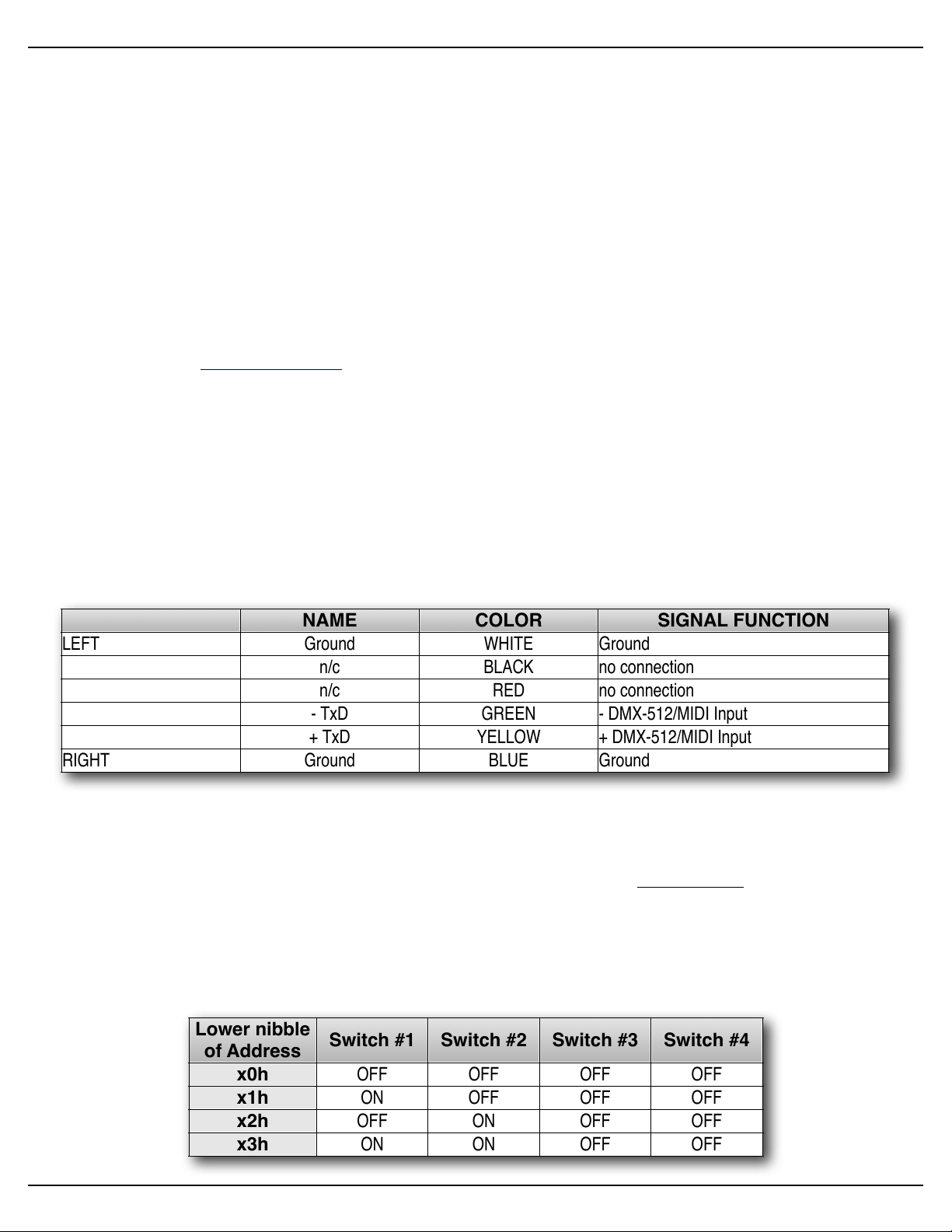
NAME
COLOR
SIGNAL FUNCTION
LEFT
Ground
WHITE
Ground
n/c
BLACK
no connection
n/c
RED
no connection
- TxD
GREEN
- DMX-512/MIDI Input
+ TxD
YELLOW
+ DMX-512/MIDI Input
RIGHT
Ground
BLUE
Ground
Lower nibble
of Address
Switch #1
Switch #2
Switch #3
Switch #4
x0h
x1h
x2h
x3h
OFF
OFF
OFF
OFFONOFF
OFF
OFF
OFFONOFF
OFFONON
OFF
OFF
Gilderfluke & Co.• 205 South Flower Street • Burbank, California 91502 • 818/840-9484 • 800/776-5972 • fax 818/840-9485
other Gilderfluke & Company devices. The only requirement is that they all be set to unique addresses.
! ! Since RS-422 is probably the most widely used of industrial data networks, a myriad of other
pieces of equipment are available which will also work with the Net Serial mode. These allow you
to do tricks like controlling the Sd-50/8 or Sd-50/40 through a wireless modem using off-the-shelf
hardware.
! ! A typical application is to use a touch screen operator interface to access and play shows.
These generally use a user definable graphical interface. You pretty much draw a button, and then
attach a string to it. When this on-screen button is pushed, this string is sent out to control the
downstream equipment.
IR Input Mode
! ! The Optoisolated/RS-422 switch on the bottom of the Sd-50/8 or Sd-50/40 can be in either
position, but RS-422 is preferred. This turns on a special serial port mode on the Sd-50/8 or Sd-50/
40 which allows it to be used with our InfraRed Transmitters and Receivers. The IR Remote mode
is typically used to trigger an animation or sound system mounted on a vehicle, turntable, or other
installation where wires can’t be used. The DMX-512/MIDI port is forced to 1200 baud and all serial
port commands are disabled on the DMX-512/MIDI port when this mode is ON. Any binary show
number received by the serial port for more than ten times will trigger the requested show. Typically the transmitters are placed along the path of the vehicle’s travel to trigger the appropriate
animation sequences at the appropriate times.
! ! The connections to the IR Remote Receiver are as follows (view is facing end of cable with
latch up):
! ! In addition to these connections, the IR Receiver requires a seven to twenty-four volt DC (Di-
rect Current) power supply connection. This is normally attached to the two pads marked “+” and
“-” on the receiver, or can be brought into the IR Receiver through the Black, Red or Blue Rj-12
wires. A jumper option allows you to bring this in through the blue wire on the RJ-11 connector.
! ! When in this mode the ‘Early Starts’ for all shows should be set to ‘NOT Steppable’. If this is
not done, then the same show will be re-triggered over and over again until the vehicle moves out
of the IR beam from the transmitter.
! ! The IR Transmitter has an eight position dipswitch which sets which show it selects. The lower
nibble of the address is set with the first four switches, and the upper nibble is set with the last four.
Valid show numbers are 01h through FFh:
Sd-50/xx Manual / October 29, 2012 2:29 PM / page 29 of 120
Page 30
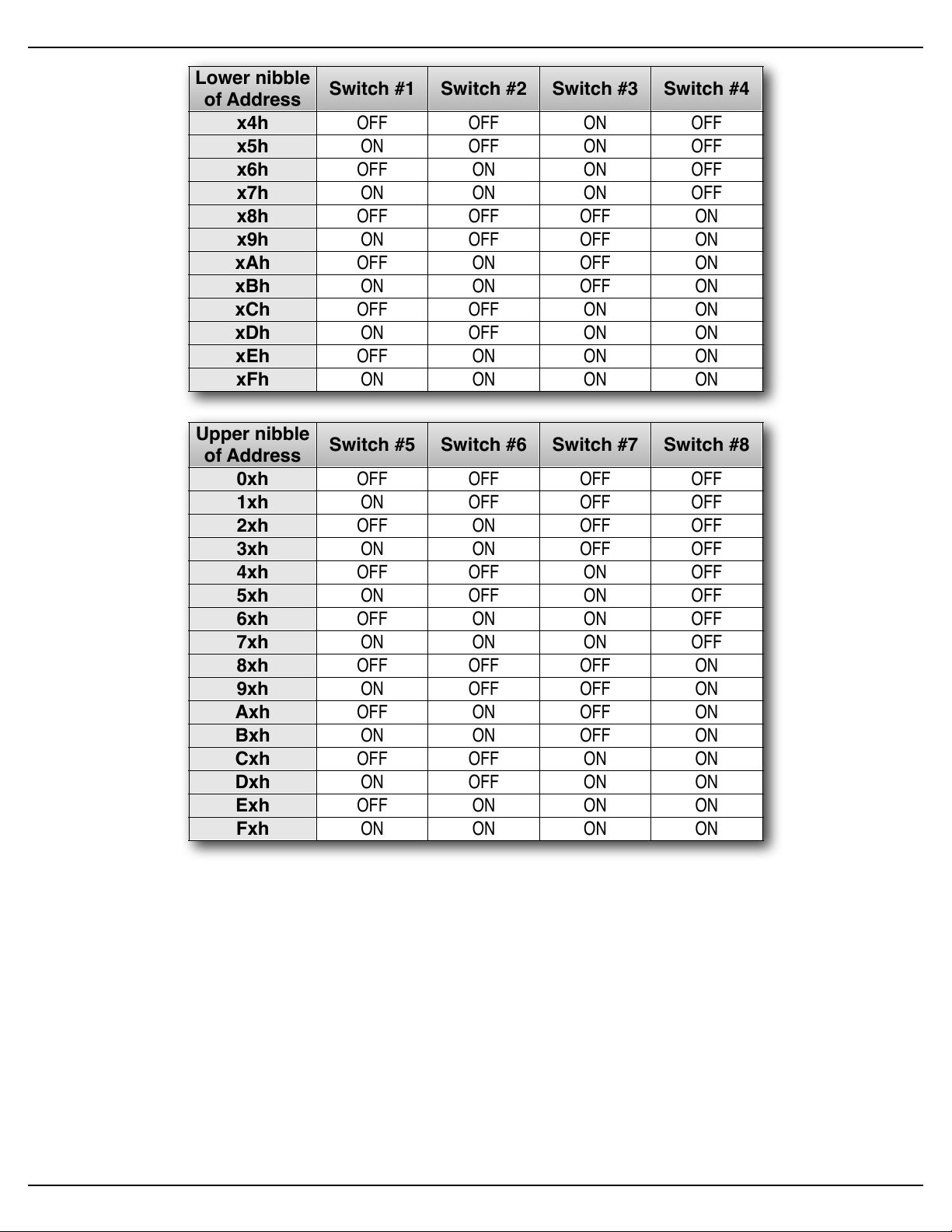
Lower nibble
of Address
Switch #1
Switch #2
Switch #3
Switch #4
x4h
x5h
x6h
x7h
x8h
x9h
xAh
xBh
xCh
xDh
xEh
xFh
OFF
OFFONOFFONOFFONOFF
OFFONON
OFFONONONOFF
OFF
OFF
OFFONON
OFF
OFFONOFFONOFFONONONOFFONOFF
OFFONONONOFFONON
OFFONONONONONON
ON
Upper nibble
of Address
Switch #5
Switch #6
Switch #7
Switch #8
0xh
1xh
2xh
3xh
4xh
5xh
6xh
7xh
8xh
9xh
Axh
Bxh
Cxh
Dxh
Exh
Fxh
OFF
OFF
OFF
OFFONOFF
OFF
OFF
OFFONOFF
OFFONON
OFF
OFF
OFF
OFFONOFFONOFFONOFF
OFFONON
OFFONONONOFF
OFF
OFF
OFFONON
OFF
OFFONOFFONOFFONONONOFFONOFF
OFFONONONOFFONON
OFFONONONONONON
ON
Gilderfluke & Co.• 205 South Flower Street • Burbank, California 91502 • 818/840-9484 • 800/776-5972 • fax 818/840-9485
IR MultiLingual Mode
! ! The Sd-50s feature a multilingual mode for installations where the same IR triggers need to
! ! To select the language, a switch is attached to the J8 input(s). If two languages are used, then
call up different Shows/SoundFIles. Most commonly, this is used to select among a bunch of different languages on an attraction. It works in conjunction with the IR receiver to modify the ShowFile
or SoundFile that the IR receiver triggers. Up to fifteen languages can be supported.
this switch is attached to just the 'A' input. If more languages are to be supported, then a 'binary'
pattern switch is attached to the J8 port to make the language selections using two, three or all four
of the J8 inputs (depending on the number of languages needed). This switch is usually set by the
ride operators or guests at the beginning of the show, but can be switched at any point in the show
if desired.
Sd-50/xx Manual / October 29, 2012 2:29 PM / page 30 of 120
Page 31

Gilderfluke & Co.• 205 South Flower Street • Burbank, California 91502 • 818/840-9484 • 800/776-5972 • fax 818/840-9485
! ! IR mode and the majority of settings are entered using the Mp3 Configurator program, just like
normal, and the shows are programmed using PC•MACs, just like normal. You will need to program additional Shows/SoundFiles to allow for each language used.
! ! The Multilingual mode is set up using GilderTerm to talk to the Sd-50/8 or Sd-50/40 directly.
On the second page of the configuration menu, the number of languages to support is entered into
eeFlag5:
! The number of languages to use is entered in HEXadecimal into eeFlag5. Valid values are
2 through 15 (02h through 0Fh). Values of#0 or 1 are ignored.
! ! The Show/SoundFile number requested (from the IR serial port) is multiplied by the number of
languages (from eeFlag5).# The result is then added to the input from the J8 port (unused inputs
from the J8 port are masked off based on the number#of languages used).
! ! The actual formula is (IR Request-1) x (number of languages) + (Language number requested
on J8 port+1) = Show/SoundFile number played
! For 2 languages, only one input on the J8 port is used: J8 input A_green_Input_0 selects
which language plays (open = language a, closed = language b)
! For 3-4 languages, two inputs on the J8 port are used: J8 input A_green_Input_0 and
B_red_Input_1 selects which language plays (0=a, 1=b, 2=c, 3=d)
! For 5-8 languages,# three inputs on the J8 port are used: # J8 input A_green_Input_0,
B_red_Input_1 and C_Blue_Input_2 selects which language plays (0=a, 1=b, 2=c, 3=d,
4=e, 5=f, 6=g, 7=h)
! For 9-15 languages,# all four inputs on the J8 port are used: # J8 input A_green_Input_0,
B_red_Input_1, C_Blue_Input_2 and D_White_Input_3 selects which language plays (0=a,
1=b, 2=c, 3=d, 4=e, 5=f, 6=g, 7=h, 8=i, 9=j, 10=k, 11=l, 12=m, 13=n, 14=o, 15=p)
Example #1: If 4 languages are needed, the value '04' would be entered into eeFlag5
! 1a)! If a binary value of '2' is entered into the J8 port to select language 'c', then an IR re-
quest for SoundFile #1 results in Show/SoundFile #3 being requested and played.
! 1b)! If the IR Trigger request Show/SoundFile #2 be played, then# Show/SoundFile #7 will
be requested and played.
! 1c)! If the IR Trigger request Show/SoundFile #10 be played, then#Show/SoundFile #39 will
be requested and played.
Example #2: Under the same conditions as in the example #1 above, but with the#'language
select' inputs set to language 'b':
! 2a)! IR request for Show/SoundFile #1 results Show/SoundFile #2 requested and played.
! 2b)! IR request for Show/SoundFile #2 results Show/SoundFile #6 requested and played.
! 2c)! IR request for Show/SoundFile #10 results Show/SoundFile #38 requested and
played.
Example #3: Another way to look at it is#(again using the four languages from example #1):
! 3a)! An IR request for Show/SoundFile #1 will play Show/SoundFIles 1, 2, 3 or 4, depend-
ing on the 'language select' inputs to the J8 port.
Sd-50/xx Manual / October 29, 2012 2:29 PM / page 31 of 120
Page 32

Gilderfluke & Co.• 205 South Flower Street • Burbank, California 91502 • 818/840-9484 • 800/776-5972 • fax 818/840-9485
! 3b)! An IR request for Show/SoundFile #2 will play Show/SoundFIles 5, 6, 7 or 8, depend-
ing on#the 'language select' inputs#to the J8 port.
! 3c)! An IR request for Show/SoundFile #3 will play Show/SoundFIles 9, 10, 11, or 12, de-
pending on#the 'language select' inputs#to the J8 port.
! 3d)! An IR request for Show/SoundFile #4 will play Show/SoundFIles 13, 14, 15 or 16, de-
pending on#the 'language select' inputs#to the J8 port.
!………
! 3j)! An IR request for Show/SoundFile #10 will play Show/SoundFIles 37, 38, 39 or 40,
depending on#the 'language select' inputs#to the J8 port.
! ! The only thing that the MultiLingual mode will not do is start a new show if the 'language select'
switch is thrown in the middle of a Show/SoundFile, unless the IR receiver is still in range of the IR
transmitter (and the Show/SoundFile is set as 'steppable'). In general, restarting a show in the middle is not the sort of thing that is generally desired. If there is a ride vehicle or other timed element
involved, it too would be recycled back to the beginning of the scene.
! ! What#the MultiLingual mode#will do if the language switch has been thrown is to play the newly
requested language on the very next IR trigger.
None
! ! If the DMX-512/MIDI input is not being used, then the DMX-512 transmission is enabled on the
DMX-512/MIDI output terminals.
G) ! DMX-512 Output (Sd-50/8, Sd-50/40)
! ! Two position Screw Terminals. DMX-512 is transmitted on this pair of screw terminals. The DMX-512
standard was developed by the United States Institute for Theatrical Technology (USITT) for a high speed
(250 KBaud) asynchronous serial data link. Although it was originally designed for controlling light dimmers,
it is now supported by hundreds of suppliers throughout the world for controlling all kinds of theatrical
equipment (fans, strobes, chain winches, wiggle lights, etc.).
a)! If running from RealTime updates through the RS-232 serial port, the DMX-512 data will always
start with the channel ‘0’ (which is channel ‘1’ on most dimmers). Data after the sixteenth channel
will be padded with ‘0’ values through the 256th byte, and then followed by two checksum bytes (if
enabled).
! ! The Show Control Outputs, Audio Level Control, And Repeater Control channels typically over-
lap with some of the lighting control channels when operated in this mode.
b)! If running from a show file which has been AutoDownloaded to the Sd-50/8 or Sd-50/40’s flash
memory, the ‘first address’ of the downloaded data will be the first DMX-512 channel to have your
programmed data in it. Channels before and after the AutoDownload data will be padded with ‘0’
values up until the 256th bytes sent, followed with a two byte checksum (if enabled). Following this
will be any additional data stored in the AutoDownload file, if there is any. After the end of the data
in the AutoDownload file, any remaining channels will be padded out through the 512th channel.
! ! The Show Control Outputs, Audio Level Control, And Repeater Control channels often overlap
with some of the lighting control channels when operated in this mode.
c)! If running from DMX-512 input data, the DMX-512 data will always start with the channel ‘0’ (which
is channel ‘1’ on most dimmers). After the 256th DMX-512 channel is sent, there will be a two byte
checksum (if enabled). Following this will be any additional data from the received DMX-512 data,
Sd-50/xx Manual / October 29, 2012 2:29 PM / page 32 of 120
Page 33

wire function
wire number
color
circuit ground1brown
Input/Output data bit #7
2
red
Gilderfluke & Co.• 205 South Flower Street • Burbank, California 91502 • 818/840-9484 • 800/776-5972 • fax 818/840-9485
if any. After the end of the DMX-512 data, any remaining channels will be padded out through the
512th channel.
H) ! Left Speaker Output (Sd-50/0, Sd-50/8, Sd-50/40)
I) ! Right Speaker Output (Sd-50/0, Sd-50/8, Sd-50/40)
!!Four position Screw Terminals. These are the two outputs of the Sd-50/xx‘s onboard Class-D ampli-
fier. This amplifier’s efficiency is near 90%. If you feed 100 Watts of twenty-four vdc into the Sd-50/xx’s
amplifier, you will get almost 100 Watts into your speakers. ‘Linear’ amplifiers have only about 20% efficiency. Fully 80% of the power you put into them goes into the heatsink as waste heat. A 100 Watt linear
amplifier would only feed 20 Watts of power into your speakers, and 80 Watts into the heatsink. This makes
the Sd-50/xx’s amplifier roughly equivalent to what would be a 400 to 500 Watt linear amplifier!
! ! If you are going to run your speakers at high SPLs, you will need to select speakers that can handle at
least a 250 Watts or more of continuous power each. Smaller speakers may clip or be damaged if run at
too high an output power level from the Sd-50/xx. Maximum output power is achieved with a pair of four
ohm speakers (or two pairs of eight ohm speakers, connected in parallel).
! ! The amplifier outputs from the Sd-50/xx can be used with speakers of four to eight ohms impedance.
As with any amplifier, you can series/parallel a number of speakers, so long as the impedance remains
within limits.
! ! The Sd-50/xx’s amplifier is well protected from short circuits and overheating, and will go back to work
a moment after a fault is removed. If the speaker impedance is too low and you are running at a high volume level, the amplifier may start to cut out. If you hear this, check the power supply voltage. If the input
voltage is dropping, you might simply be drawing too much power for the power supply and a larger supply
may fix your problem. If the power supply is OK, and you can’t increase the speaker impedance, then you
might simply be asking too much of the Sd-50/xx’s amplifier, and need to turn down the volume a tad.
! ! If you wish to comply with FCC and CE standards for radio frequency emissions, you should use
shielded speaker wires with the Sd-50/xx. The shield should be attached to the power supply ‘negative’
terminal, which is immediately adjacent to the speaker terminals. This will not affect the sound quality from
the Sd-50/xx, but will make the FCC and CE folks happy. Shielded speaker lines were used during all CE/
FCC certification testing.
! ! External amplifiers can be fed from the Line Level Outputs if more power than this is needed.
J) ! Left Line Output (Sd-50/0, Sd-50/8, Sd-50/40)
K) ! Right Line Output (Sd-50/0, Sd-50/8, Sd-50/40)
!!Female RCA jacks. These are the two line level outputs from the .Mp3/.wav player. They are
used for attaching an external amplifier to the Sd-50/xx.
L) ! ʻ¼ J6ʼ Inputs/Outputs (Sd-50/0, Sd-50/8, Sd-50/40)
! ! Ten position IDS Connector. Note that this individual pins on this port can be used as inputs or outputs.
If a pin is being used for one, it is not normally used as the other at the same time.
! ! Each ‘" J6’ cable is arranged in the following order:
Sd-50/xx Manual / October 29, 2012 2:29 PM / page 33 of 120
Page 34

wire function
wire number
color
Input/Output data bit #6
3
orange
Input/Output data bit #5
4
yellow
Input/Output data bit #4
5
green
Input/Output data bit #3
6
blue
Input/Output data bit #2
7
violet
Input/Output data bit #1
8
gray
Input/Output data bit #0
9
white
+ vdc unregulated power supply
10
black
Gilderfluke & Co.• 205 South Flower Street • Burbank, California 91502 • 818/840-9484 • 800/776-5972 • fax 818/840-9485
! ! Depending on the type of Sd-50/xx, this connection can serve a number of different functions:
Sd-50/0: These pins are used to connect to the eight optically isolated trigger inputs which are used to
select SoundFiles, start, mute, half mute, pause, or unmute the .Mp3/.wav player. What each of
these pins will do is set using the Input Setup tab in the Mp3 Config.exe’ program.
Sd-50/8: This connector is used for eight optically isolated trigger inputs AND eight Show Control Out-
puts.
! ! These inputs can be used to trigger, mute, unmute, etc. the .Mp3/.wav player, or to request
and play shows from the Show control half of the Sd-50/8 or Sd-50/40.
! ! These are not normally used as inputs on Sd-50/8s or Sd-50/40s. They are typically config-
ured not to do anything using the Input Setup tab in the Mp3 Config.exe’ program. The Animation
‘Virtual’ Audio Trigger Input channel is used instead for controlling the Audio Playback (using the
Animation Input Setup tab in the Mp3 Config.exe’ program). This leaves all eight of these pins
available for Show Control Outputs.
! ! An exception to this is when you need to use an actual switch input independent of the show
that is being run to mute or stop the audio. An example of this would be a switch input to half-mute
the audio during PA announcements. The input to the .Mp3/.wav player is configured for the de-
sired function using the Input Setup tab in the Mp3 Config.exe’ program. The corresponding Show
Control output is usually programmed so that it never goes active, so that it does not interfere with
the operation of the .Mp3/.wav player. If the Show Control output does go active, it will have the
same effect as an externally attached switch would have.
! ! These eight inputs can be used to select and play individual shows using a individual bits or
binary patterns on the inputs. They are used for starting shows only when more than the four ‘J8’
inputs are needed.
! ! The individual bits of the ‘" J6’ port can also be selected to use as ServoMotor PWM outputs.
When a pin used for ServoMotor PWM outputs, it is unavailable for either input to trigger sounds
and shows, or as a standard Show Control Output.
Sd-50/40: This connector is also used as the optically isolated trigger inputs the .Mp3/.wav player, and
the last eight of the forty Show Control outputs. Other than that, it is identical to a Sd-50/8.
! Outputs via the ʻ¼ J6ʼ port
! ! The eight pins of the ‘" J6’ port can be used as digital Show Control output for the on/off con-
trol of solenoid valves, relays, lights or anything else that can be controlled by an electrical signal.
In every way the ‘" J6’ port outputs are identical to the normal ‘J6’ port found on the Sd-50/40.
Details on the connection can be found there.
Sd-50/xx Manual / October 29, 2012 2:29 PM / page 34 of 120
Page 35

SUPPLY (not used)
(Brown) PIN #1
(red) PIN #2
(orange) PIN #3
(yellow) PIN #4
(green) PIN #5
(blue) PIN #6
(violet) PIN #7
(grey) PIN #8
(white) PIN #9
(black) PIN #10
GROUND
DATA BIT 7
DATA BIT 6
DATA BIT 5
DATA BIT 4
DATA BIT 3
DATA BIT 2
DATA BIT 1
DATA BIT 0
+ 5 to 24 VDC SUPPLY
GROUND
DATA BIT 7
DATA BIT 6
DATA BIT 5
DATA BIT 4
DATA BIT 3
DATA BIT 2
DATA BIT 1
DATA BIT 0
Internal Power
External Power
(Brown) PIN #1
(red) PIN #2
(orange) PIN #3
(yellow) PIN #4
(green) PIN #5
(blue) PIN #6
(violet) PIN #7
(grey) PIN #8
(white) PIN #9
(black) PIN #10
Gilderfluke & Co.• 205 South Flower Street • Burbank, California 91502 • 818/840-9484 • 800/776-5972 • fax 818/840-9485
! Inputs via the ʻ¼ J6ʼ port
! ! For a Sd-50/0, the ‘" J6’ input is strictly an .mp3/.wav input. It is optically isolated. It can be set
to run from an external power source or the same power as the Sd-50/xx (default configuration).
This is selected by moving the switch on the bottom of the Sd-50/xx. The ‘external’ setting is used
when you want to completely isolate the Sd-50/xx from the switch closures that control it.
! ! The input from Kp-200 keypad(s) to the ‘" J6’ input is a ‘straight wire’, using a ten position
ribbon cable and a 10-IDS connector at each end of the connection. If you want to optoisolate the
connection, attach a nine to twenty-four vdc power supply to the Kp-200, and throw the switch on
the bottom of the Sd-50/8 or Sd-50/40 into the ‘isolated’ position. If you don’t need to optoisolate
the Kp-200, then put the switch on the bottom of the Sd-50/8 or Sd-50/40 into the ‘internal’ power
position. The Kp-200 needs no power other than what it will get from the Sd-50/8 or Sd-50/40
through the ‘" J6’ cable.
!!On a Sd-50/8 or Sd-50/40, this input/output is almost always run in the ‘Internal’ power mode.
The only exception to this is if you are going to be running the devices controlled by these eight
Show Control outputs from a different voltage from the rest of the Sd-50/8 or Sd-50/40. As an example, if the Sd-50/8 or Sd-50/40 is running from twenty-four vdc, and you need to control eight
twelve vdc relays, you can power this one port from a twelve vdc power supply separate from the
main one (you will need to connect the grounds of the two power supplies).
! ! ServoMotor PWM via the ʻ¼ J6ʼ port
! ! If you are running typical ServoMotors, you have two ways to connect them. The first way is
used if you don’t need to use any of the other pins on the ‘" J6’ port for anything other than ServoMotors. The second is used if you need to use some of the pins of the ‘" J6’ port for other purposes than ServoMotors:
Sd-50/xx Manual / October 29, 2012 2:29 PM / page 35 of 120
Page 36

(to Sd-50)
Set switch on bottom of Sd-50 for
ʻexternalʼ power for the ʻ1/4 J6ʼ port
Resistor may be needed by
some ServoMotors
Ground for Sd-50's and Servo-
Motor(s) must be connected
Motor
typ. of 8 Servos
gnd
d7
d6
d5
d4
d3
d2
d1
d0
+sup
1/4 J6
1
2
3
4
5
6
7
8
9
10
-
+
5 vdc Power
-
+
12 to 24 vdc Pwr
Power to Sd-50
1KΩ
Resistor
Common Ground
ServoMotor Power
PWM (control)
Common Ground
(to Sd-50)
Resistor may be needed by
some ServoMotors
Ground for Sd-50's and Servo-
Motor(s) must be connected
Set switch on bottom of Sd-50 for
'internalʼ power on the ʻ1/4 J6ʼ port
Motor
typ. of 8 Servos
gnd
d7
d6
d5
d4
d3
d2
d1
d0
+sup
1/4 J6
1
2
3
4
5
6
7
8
9
10
-
+
5 vdc Power
-
+
12 to 24 vdc Pwr
Power to Sd-50
1KΩ
Resistor
Common Ground
Diode
ServoMotor Power
PWM (control)
Common Ground
Gilderfluke & Co.• 205 South Flower Street • Burbank, California 91502 • 818/840-9484 • 800/776-5972 • fax 818/840-9485
1. When running ONLY ServoMotors on the ‘" J6’ connector, the Sd-50/8 or Sd-50/40 is run from a
typical twelve to twenty-four vdc
power supply, just as you would
normally do. A separate five vdc
power supply used to provide power
to the ServoMotor(s). Select ‘exter-
nal’ power for the ‘" J6’ port by
moving the switch on the bottom of
the Sd-50/xx. Run positive five vdc
into pin #10 of the ‘" J6’ connector
and the ground side of the five vdc
power supply into pin #1 of the ‘"
J6’ connector. The positive five vdc
is also connected to the power and
ground pins of the ServoMotor. The
‘grounds’ of both power supplies
must be connected together. The
ServoMotor’s PWM ‘control’ pin is
attached to the output pin that is be-
ing used for providing the ServoMo-
tor the PWM control signal it needs. Since the ‘" J6’ port is running on the external five vdc power,
this largely precludes using any of the other pins on this port for anything other than ServoMotor
PWM outputs.
2. When running a mix of ServoMotor(s) and other functions on the ‘" J6’ connector, the ServoMotors must be protected from the 12 to 24 vdc that is running the other functions. The Sd-50/8 or Sd-
50/40 is run from a typical twelve to
twenty-four vdc power supply, just
as you would normally do. A sepa-
rate five vdc power supply used to
provide power to the ServoMotor(s).
Select ‘Internal’ power for the ‘" J6’
port by moving the switch on the
bottom of the Sd-50/xx. The positive
five vdc and ground pins from the
five volt power supply are connected
to the power and ground pins of the
ServoMotor. The ‘grounds’ of both
power supplies must be connected
together. The ServoMotor’s PWM
‘control’ pin is attached to the output
pin that is being used for providing
the ServoMotor the PWM control
signal it needs through a small sig-
nal diode. Typical diodes are
1N4148 or 1N914, but almost any diode will work. The ‘cathode’ end of the diode (indicated by the
stripe) is towards the connector on the Sd-50/8 or Sd-50/40. This diode keeps the higher voltage
that is running the Sd-50/8 or Sd-50/40 from getting to the ServoMotor. Any input/output pins on
this port that are not being used for ServoMotor PWM can be used for normal input or output.
! ! ServoMotors are typically run at somewhere around five vdc. If your ServoMotor is made to run
at a different voltage than this (twelve to twenty-four vdc), it will likely be a very big, strong, and
Sd-50/xx Manual / October 29, 2012 2:29 PM / page 36 of 120
Page 37

+5 to 24 VDC SUPPLY
Switching Negative Side
+5 to 24 VDC SUPPLY
+5 to 24 VDC SUPPLY
+5 to 24 VDC SUPPLY
+5 to 24 VDC SUPPLY
Switching Positive Side
+5 to 24 VDC SUPPLY
+5 to 24 VDC SUPPLY
+5 to 24 VDC SUPPLY
- 'A'/Green Input
+ 'A'/Green Input
- 'B'/Red Input
+ 'B'/Red Input
- 'C'/Blue Input
+ 'C'/Blue Input
- 'D'/White Input
+ 'D'/White Input
+ 'A'/Green Input
- 'A'/Green Input
+ 'B'/Red Input
+ 'C'/Blue Input
- 'B'/Red Input
- 'C'/Blue Input
+ 'D'/White Input
- 'D'/White Input
Gilderfluke & Company • Burbank, California
'A'
'B'
'C'
'D'
3
7
6
5
4
2
1
0
Fuse
7
6
5
4
3
2
1
0
Fuse
Fu se
3 2 1 0
3 2 1 0
7
6
5
4
3
2
1
0
4
4
Power
12–24 vdc
DMX/MIDI/
RS- 422
In O ut
Speak er s
(4! to 8!)
Left Ri ght
Sd-50/40Sd-50/40
Switch
'D'
Switch
'C'
Switch
'B'
Switch
'A'
ground
Gilderfluke & Co.• 205 South Flower Street • Burbank, California 91502 • 818/840-9484 • 800/776-5972 • fax 818/840-9485
heavy-duty motor with separate power and control connections. Typically power for such a ServoMotor will the same twelve or twenty-four vdc that the Sd-50/8 or Sd-50/40 thrives on. Connect the
motor as shown in its instructions. The PWM input (the part that connects to the Sd-50/8 or Sd-50/
40) is still likely to be run at five vdc, rather than the higher voltage that the ServoMotor is run at.
Check the specifications for the motor you are using before you run twelve to twenty-four vdc into
the PWM input on the ServoMotor.
M)! J8 ʻAʼ, ʻBʼ, ʻCʼ & ʻDʼ inputs (Sd-50/8, Sd-50/40)
! ! These are four non-polarized optically isolated digital inputs which can be used to start, stop,
pause or select specific show sequences to play on the Show Control of the Sd-50/8 or Sd-50/40.
! ! In most cases, you will simply be ‘borrowing the power for these switches from the adjacent power ter-
minals:
! ! Any event can be triggered on either the ‘closing’ or ‘opening’ edge of any input. A ‘closing’ is when you
apply a voltage to an input. An ‘opening’ is when that voltage is removed. The inputs can be triggered on
any voltage from five to twenty-four vdc. If you don’t have an external source of power for these two inputs,
you can ‘steal’ some juice from the Sd-50/8s or Sd-50/40s power supply connections. Conveniently, there
are ‘power’ screw terminals immediately adjacent. You can pick up whatever power is being used to run the
Sd-50/8 or Sd-50/40 from these two screw terminals.
Sd-50/xx Manual / October 29, 2012 2:29 PM / page 37 of 120
Page 38

Show #
ʻAʼ
ʻBʼ
ʻCʼ
ʻDʼ
comment
0123456789101112131415off
off
off
off
(there ain’t no show ‘0’)
on
off
off
off
offonoff
offonon
off
off
off
offonoffonoffonoff
offonon
offonononoff
off
off
offonon
off
offonoffonoffonononoffonoff
offonononoffonon
offonononononon
on
Gilderfluke & Co.• 205 South Flower Street • Burbank, California 91502 • 818/840-9484 • 800/776-5972 • fax 818/840-9485
! ! These four inputs are uncommitted optoisolators. Effectively, you are sending the external control sig-
nal into a LED which has a resistor wired in series. This requires external power be supplied from somewhere. If the device you are controlling the input from supplies power, then all is well. If you are wiring
these inputs to simple dry switch closures, you will need to ‘steal’ the power for them from somewhere.
!!J8 ʻAʼ, ʻBʼ, ʻCʼ & ʻDʼ Binary:
!!The four optically isolated digital inputs can be used to select up to fifteen different shows directly with
a binary weighted pattern of bits. If you need direct access to more than fifteen shows, use the ‘" J6’ input
instead of the ‘J8’ inputs.
! ! To use the ‘J8’ inputs for binary show selections, you must set all four of these inputs (both opening &
closing edges) as ‘unused’ when you generate your AutoDownload file from PC•MACs. The binary pattern
is applied as follows:
! ! If you are using our KP-200 for selecting and playing shows, it is wired as follows. The connection to
the KP-200 is through a ten position ribbon cable. Power for the KP-200 in this example is being ‘borrowed’
from the Sd-50/8 or Sd-50/40. If you are going to be running the cable from the KP-200 to the Sd-50/8 or
Sd-50/40 a long distance, or if you are picking up audio ‘noise’ through this input, you can use a separate
power supply to completely isolate the KP-200 and the Sd-50/8 or Sd-50/40.
Sd-50/xx Manual / October 29, 2012 2:29 PM / page 38 of 120
Page 39

Gilderfluke & Company • Burbank, California
'A'
'B'
'C'
'D'
3
7
6
5
4
2
1
0
Fuse
7
6
5
4
3
2
1
0
Fuse
Fu se
3 2 1 0
3 2 1 0
7
6
5
4
3
2
1
0
4
4
Power
12–24 vdc
DMX/MIDI/
RS- 422
In O ut
Speak er s
(4! to 8!)
Left Ri ght
Sd-50/40Sd-50/40
#10 Black (12–24 vdc)
#2 Red (bit 7)
#3 Orange (bit 6)
#4 Yellow (bit 5)
#5 Green (bit 4)
#6 Blue (bit 3)
#7 Violet (bit 2)
#8 Grey (bit 1)
#9 White (bit 0)
Ribbon cable to KP-200
#1 Brown (ground)
Gilderfluke & Co.• 205 South Flower Street • Burbank, California 91502 • 818/840-9484 • 800/776-5972 • fax 818/840-9485
! ! The ‘D’/White input can be used to disable scans of the RTC schedules when the input is opened. This
can be used to stop sounds and shows from playing automatically when they shouldn’t. Examples of where
this feature can be used are:
a)! In a church bell tower, where a simple switch opening can be used to temporarily disable bells from
ringing during a service.
b)! In a Theme Park or museum, where this input can be tied to the existing power management grid
to disable scheduled shows and sounds when the attraction is closed.
! ! If you have a show or sound which should not be interrupted by a scheduled event. You can set the
show/sound so that it ‘can not’ be stepped on. The schedule may try to start a show or sound, but the request will not be honored if it has been set as ‘unsteppable’.
N) ! ʻJ6ʼ Show Control Outputs (Sd-50/40)
!!Forty Position IDS Connector. Each Sd-50/40 has forty outputs. This connector is used for the first
thirty-two outputs. The last eight appear on the ‘" J6’ connector on the back of the Sd-50/40.
! ! These ‘J6’ Show Control outputs are identical to the standard outputs used on all Gilderfluke & Com-
pany Show Control Systems. Forty and ten position transition connectors are available for the Sd-50/8s or
Sd-50/40s to adapt the ribbon cables to screw terminals, and are included in the ‘starter kit’.
! ! The output connections for all Gilderfluke & Company Show Control Systems are through ‘J6’ output
cables. These are forty wire ribbon cables which are made up of four identical eight-bit wide ‘channels’. A
‘J6’ cable is often split up into four individual channels. Each ‘" J6’ ribbon cable is made up of ten wires,
and can be used to control eight individual ‘digital’ (off/on) devices, or one eight-bit wide ‘analog’ device.
Each group of ten wires also includes a common power supply and ground wire.
! ! To simplify wiring to any Gilderfluke animation system, the connectors used on the ‘" J6’ cables are
! ! If attaching discrete wires from the ‘J6’ ribbon cable connector presents a problem, we have forty and
what are called ‘insulation displacement’ (IDS) connectors. These simply snap on to an entire cable, automatically ‘displacing’ the wire insulation and making contact with the wires within. This means that an entire
ten wire cable can be terminated in seconds. All connectors are polarized, to keep them from being
plugged in backwards. Although there are tools made specifically for installing these connectors, the tool
we find works best is a small bench vise.
ten position transition connectors are available for the Sd-50/8s or Sd-50/40s to adapt the ribbon cables to
Sd-50/xx Manual / October 29, 2012 2:29 PM / page 39 of 120
Page 40

typical output
typical input
fuse
flyback
diode
supply
supply
400ma.
600ma.
500ma.
300ma.
200ma.
100ma.
2
3
4
5
8
7
6
Output Duty Cycle
Allowable Peak Collector Current @ 70ºC
Peak Collector Current as a function
of Output Duty Cycle
10%
20%
30%
40%
50%
60%
70%
80%
90%
100%
Number of outputs
conducting
simultaneously
Gilderfluke & Co.• 205 South Flower Street • Burbank, California 91502 • 818/840-9484 • 800/776-5972 • fax 818/840-9485
screw terminals. Ribbon cable to screw terminal adapters are also available from a number of different
sources.
! ! Any eight digital devices or one eight-bit analog device can be connected to any ‘" J6’ cable as shown.
The LED between the ground (pin #1 brown) wire and supply (pin #10 black) wire acts as an indicator that
is lit if the fuse for that channel is OK.
! ! All outputs are open collector switches to ground. Each output is individually protected from over cur-
rent conditions and transient spikes. Flyback diodes are included in the outputs for driving inductive loads.
Larger inductive loads may require flyback diodes be installed directly across the loads. Power is supplied
through a diode and a solid state circuit breaker to the common pin(s) on the connector. A safe level of current is 150 milliamperes simultaneously on each output. This is sufficient to drive most small relays, valves
and other similar loads directly. If fewer than eight outputs are on at one time, then the outputs are rated as
shown in the following chart.
! ! The supply line for each " J6 is ‘Polyswitch fused’ for one amp. You should treat each " J6 as an indi-
vidual, and not cross the outputs or supply lines from one channel to the lines from any other channel. Doing this won’t cause any damage, but can reduce the protection for the outputs that the fuses normally provide.
! ! The current Output Capacity of each output is as shown in the following chart:
!!
Sd-50/xx Manual / October 29, 2012 2:29 PM / page 40 of 120
Page 41

wire function
wire number
color
circuit ground1brown
channel 0 data bit #7
2
red
channel 0 data bit #6
3
orange
channel 0 data bit #5
4
yellow
channel 0 data bit #4
5
green
channel 0 data bit #3
6
blue
channel 0 data bit #2
7
violet
channel 0 data bit #1
8
gray
channel 0 data bit #0
9
white
+ vdc unregulated power supply
10
black
circuit ground11brown
channel 1 data bit #7
12
red
channel 1 data bit #6
13
orange
channel 1 data bit #5
14
yellow
channel 1 data bit #4
15
green
channel 1 data bit #3
16
blue
channel 1 data bit #2
17
violet
channel 1 data bit #1
18
gray
channel 1 data bit #0
19
white
+ vdc unregulated power supply
20
black
circuit ground21brown
channel 2 data bit #7
22
red
channel 2 data bit #6
23
orange
channel 2 data bit #5
24
yellow
channel 2 data bit #4
25
green
channel 2 data bit #3
26
blue
channel 2 data bit #2
27
violet
channel 2 data bit #1
28
gray
channel 2 data bit #0
29
white
+ vdc unregulated power supply
30
black
circuit ground31brown
channel 3 data bit #7
32
red
channel 3 data bit #6
33
orange
channel 3 data bit #5
34
yellow
channel 3 data bit #4
35
green
channel 3 data bit #3
36
blue
channel 3 data bit #2
37
violet
channel 3 data bit #1
38
gray
channel 3 data bit #0
39
white
+ vdc unregulated power supply
40
black
Gilderfluke & Co.• 205 South Flower Street • Burbank, California 91502 • 818/840-9484 • 800/776-5972 • fax 818/840-9485
Each ‘J6’ cable is arranged in the following order:
Sd-50/xx Manual / October 29, 2012 2:29 PM / page 41 of 120
Page 42

Gilderfluke & Co.• 205 South Flower Street • Burbank, California 91502 • 818/840-9484 • 800/776-5972 • fax 818/840-9485
! ! If the loads you are controlling with the the Sd-50/8 or Sd-50/40 controller are at a higher voltage and/
or current than it will provide directly, then relays can be added on the Show Control Outputs (or DMX-512
Outputs) to control any sized loads.
! ! You can provide these relays yourself, or Gilderfluke & Co. has several ready-to-use relay boards
available:
DPDT relay board: A set of eight electromechanical relays with double pole/double throw contacts
rated at five amps each. Connected to the Sd-50/8 or Sd-50/40 controller by a ‘" J6’ ribbon cable
from the Digital Show Control outputs.
Reed relay board: A set of eight small electromechanical relays with normally open contacts rated at
150 ma each. Connected to the Sd-50/8 or Sd-50/40 controller by a ‘" J6’ ribbon cable from the
Digital Show Control outputs.
Solid State Relay Fanning Strip: For connecting up to eight popular ‘hockey puck’ style relays to a ‘"
J6’ output cable. These are available with capacities of up to 75 amps each. Connected to the Sd-
50/8 or Sd-50/40 controller by a ‘" J6’ ribbon cable from the Digital Show Control outputs.
Pb-08, Pb-16, Pb-24 or Pb-32: Small AC (Alternating Current) or DC (Direct Current) relays rated for
3.5 amps each. Each relay is protected by an easily replaced standard fuse. Connected to the Sd-
50/8 or Sd-50/40 controller by a ‘J6’ ribbon cable from the Digital Show Control outputs.
Pb-DMX/08, Pb-DMX/16, Pb-DMX/24 or Pb-DMX/32: Small AC (Alternating Current) or DC (Direct
Current) relays rated for 3.5 amps each. Each relay is protected by an easily replaced standard
fuse. Connected to the Sd-50/8 or Sd-50/40 controller by a single twisted pair of wires from the
DMX-512 outputs.
LC-8SP: A set of eight solid state relays with mounted in a 19” rack mountable metal box. Line cord in,
and eight individual duplex outlets for connecting you loads. Connected to the Sd-50/8 or Sd-50/40
controller by a ‘" J6’ ribbon cable from the Digital Show Control outputs.
Sd-50/xx Manual / October 29, 2012 2:29 PM / page 42 of 120
Page 43

Gilderfluke & Co.• 205 South Flower Street • Burbank, California 91502 • 818/840-9484 • 800/776-5972 • fax 818/840-9485
Defaults for Sd-50/0s, Sd-50/8s and Sd-50/40s
Although almost everything can be adjusted on a Sd-50/xx, almost all applications will be able to use
the ‘default’ settings. There are a number of ways to get a Sd-50/xx to load to the default settings:
a)! In the ‘Mp3 Config.exe’ program, you can select the type of player you are using from the ‘player type’
menu at the top of the window. Under the Edit menu, select ‘Reset Everything to defaults’. Save the new
configuration to the Sd/MMC flash card you will be using. When you move this Sd/MMC flash card to the
Sd-50/xx, it will load this configuration.
b)! If you have a Sd/MMC flash card inserted in the Sd-50/xx, but that card does not have a Sd-50.cfg file on
it, the Sd-50/xx will create a default audio configuration. These defaults will only affect the .Mp3/.wav
player. The settings for the animation playback can be adjusted from using GilderTerm through the Sd-50/
xx’s serial port. Once you have entered the configuration mode for the Sd-50/xx, you can select the ‘reload
defaults’ command to reload the defaults for the animation playback too. Changes you make in the configuration through the serial port and GilderTerm will ‘stick’ until you change them again, or you insert a card
with a Sd-50.cfg file loaded on it. The Sd-50/xx will load any Sd-50.cfg file as soon as it finds one.
Sd-50/0 (audio only) Defaults
Volume to defaults. All sounds do nothing at end. Play Lists unused. Amplifier Enabled. The Animation ‘Virtual’
Audio Trigger Input which is used to trigger SoundFiles from the Show Control data is entirely unused (all bits set to
‘Unused’).
The ‘" J6’ Trigger Inputs set as following:
a)! If there are Zero SoundFiles in the Sounds folder, the ‘" J6’ Trigger Inputs is set as follows:
! The ‘" J6’ Trigger Inputs are unused. All bits set to ‘Unused’.
b)! If there are between one and eight SoundFiles in the Sounds folder, the ‘" J6’ Trigger Inputs is set
for ‘Direct Selection’ of the SoundFiles: Bit #0=SoundFile 1, bit #1=SoundFile 2, bit #2=SoundFile
3, bit #3=SoundFile 4, bit #4=SoundFile 5, bit #5=SoundFile 6, bit #6=SoundFile 7, bit #7=SoundFile 8.
b.1)! If seven or less SoundFiles are found, then the ‘" J6’ Trigger Inputs bit #7 becomes
‘Stop Now’.
b.2)! If six or less SoundFiles are found, then the ‘" J6’ Trigger Inputs bit #6 becomes full
mute in one second on closing, and unmute in one second upon opening.
b.3)! If five or less SoundFiles are found, then the ‘" J6’ Trigger Inputs bit #5 becomes half
mute in one second on closing, and unmute in one second upon opening.
b.4)! If four or less SoundFiles are found, then the ‘" J6’ Trigger Inputs bit #4 becomes un-
mute in one second on closing.
b.5)! If three or less SoundFiles are found, then the ‘" J6’ Trigger Inputs bit #3 becomes
mute in one second on closing.
b.6)! If two or less SoundFiles are found, then the ‘" J6’ Trigger Inputs bit #2 becomes half
mute in one second on closing.
c)! If there are nine or more SoundFiles in the Sounds folder, the ‘" J6’ Trigger Inputs is set for binary
selection of the SoundFiles: Bits 0-? are used to binary address the available SoundFiles.
Sd-50/xx Manual / October 29, 2012 2:29 PM / page 43 of 120
Page 44

Gilderfluke & Co.• 205 South Flower Street • Burbank, California 91502 • 818/840-9484 • 800/776-5972 • fax 818/840-9485
c.1)! If 127 or less SoundFiles are found, then the ‘" J6’ Trigger Inputs bit #7 becomes
‘Stop Now’.
c.2)! If 63 or less SoundFiles are found, then the ‘" J6’ Trigger Inputs bit #6 becomes full
mute in one second on closing, and unmute in one second upon opening.
c.3)! If 31 or less SoundFiles are found, then the ‘" J6’ Trigger Inputs bit #5 becomes half
mute in one second on closing, and unmute in one second upon opening.
c.4)! If 15 or less SoundFiles are found, then the ‘" J6’ Trigger Inputs bit #4 becomes un-
mute in one second on closing.
Sd-50/8 Defaults
Serial address to 00h, First animation output at 00h, MPU triggers at 01h, Volume left @ 02h (but disabled),
Volume right @ 03h (but disabled), DMX Rx Enabled, Flash enabled, DMX Checksum Enabled, DST rules set for
the US standards (as of 2007), First ServoMotor @ 02h (but disabled), RTC input set for GPS, time zone set to
-8:00, All ‘" J6’ Trigger Inputs is entirely unused (all bits set to ‘Unused’).
The Animation ‘Virtual’ Audio Trigger Input which is used to trigger SoundFiles from the Show Control data is
set as follows:
a)! If there are Zero SoundFiles in the Sounds folder:
! The Animation ‘Virtual’ Audio Trigger Input are unused. All bits set to ‘Unused’.
b)! If there are between one and eight SoundFiles in the Sounds folder, the Animation ‘Virtual’ Audio
Trigger Input is set for ‘Direct Selection’ of the SoundFiles: Bit #0=SoundFile 1, bit #1=SoundFile 2,
bit #2=SoundFile 3, bit #3=SoundFile 4, bit #4=SoundFile 5, bit #5=SoundFile 6, bit #6=SoundFile
7, bit #7=SoundFile 8.
b.1)! If seven or less SoundFiles are found, then the Animation ‘Virtual’ Audio Trigger Input
bit #7 becomes ‘Stop Now’.
b.2)! If six or less SoundFiles are found, then the Animation ‘Virtual’ Audio Trigger Input bit
#6 becomes full mute in one second on closing, and unmute in one second upon
opening.
b.3)! If five or less SoundFiles are found, then the Animation ‘Virtual’ Audio Trigger Input bit
#5 becomes half mute in one second on closing, and unmute in one second upon
opening.
b.4)! If four or less SoundFiles are found, then the Animation ‘Virtual’ Audio Trigger Input bit
#4 becomes unmute in one second on closing.
b.5)! If three or less SoundFiles are found, then the Animation ‘Virtual’ Audio Trigger Input
bit #3 becomes mute in one second on closing.
b.6)! If two or less SoundFiles are found, then the Animation ‘Virtual’ Audio Trigger Input bit
#2 becomes half mute in one second on closing.
c)! If there are nine or more SoundFiles in the Sounds folder, the Animation ‘Virtual’ Audio Trigger In-
put is set for binary selection of the SoundFiles:! Bits 0-? are used to binary address the available
SoundFiles.
c.1)! If 127 or less SoundFiles are found, then the Animation ‘Virtual’ Audio Trigger Input bit
#7 becomes ‘Stop Now’.
Sd-50/xx Manual / October 29, 2012 2:29 PM / page 44 of 120
Page 45

Gilderfluke & Co.• 205 South Flower Street • Burbank, California 91502 • 818/840-9484 • 800/776-5972 • fax 818/840-9485
c.2)! If 63 or less SoundFiles are found, then the Animation ‘Virtual’ Audio Trigger Input bit
#6 becomes full mute in one second on closing, and unmute in one second upon
opening.
c.3)! If 31 or less SoundFiles are found, then the Animation ‘Virtual’ Audio Trigger Input bit
#5 becomes half mute in one second on closing, and unmute in one second upon
opening.
c.4)! If 15 or less SoundFiles are found, then the Animation ‘Virtual’ Audio Trigger Input bit
#4 becomes unmute in one second on closing.
Sd-50/40 Defaults
All settings the same as the Sd-50/8, except
MPU triggers addressed at 05h, Volume left @ 06h (but disabled), Volume right @ 07h (but disabled), First
ServoMotor @ 06h (but disabled).
Sd-50/WWV8 Defaults (w/ ʻatomicʼ clock)
All settings the same as the Sd-50/8. Reset the RTC enabled and set for 3:05:00 AM, and the Schedule disable
on C/Blue is disabled.
Sd-50/WWV40 Defaults (w/ ʻatomicʼ clock)
All settings the same as the Sd-50/40. Reset the RTC enabled and set for 3:05:00 AM, and the Schedule disable on C/Blue is disabled.
Sd-50/xx Manual / October 29, 2012 2:29 PM / page 45 of 120
Page 46

Gilderfluke & Co.• 205 South Flower Street • Burbank, California 91502 • 818/840-9484 • 800/776-5972 • fax 818/840-9485
What You Should And Shouldnʼt See
Any Sd-50/xx should be booted and begin counting sounds within five seconds. If it takes longer than
this, it is an indication that it is having a problem reading the files from the Sd/MMC card.
The time it takes to count the sounds once it starts is dependent on the number of sounds that are
loaded, the speed of your Sd/MMC card, and the length of the sound FileNames. Names which are over
8.3 characters long will take longer to read, as their names span across multiple directory entries (that’s a
DOS/Windows thing). Shorter names (8.3 characters or shorter) are faster to access and count.
The normal boot sequence for a Sd-50/xx:
1)! The ‘Sd access’ LED will be on at power up, as the audio processor has yet to be initialized. The next three
steps are done by the MCU, while it holds the audio processor in reset.
2)! Within five seconds, you should see the ‘Sd access’ LED turn off and the ‘DMX’ and ‘Sd access’ LEDs flash
as the ‘Sd-50.cfg’ file is read from the Sd/MMC flash card. If the ‘Sd-50.cfg’ file has changed (different time
or date), then it will be loaded in its entirety. If it is the same as the last time the unit booted, then it will load
the audio portion of the configuration, but use the existing animation configuration. This is what allows you
to make minor changes in the configuration through the serial menus, and have them ‘stick’ until the
‘Sd-50.cfg’ file changes.
3)! If the AutoDownload (.a00), schedule, or GPS files are different from what has already been loaded into the
Sd-50/xx’s internal flash memory (different name, date or time), these files will be read from the Sd/MMC
flash card into the units internal flash. While it is doing an upload, you will see an alternating flash on the
‘heart’ and ‘DMX’ LEDs and a slower pulsing on the ‘Show Run’ LED.
4)! If there is a firmware file on the Sd/MMC flash card which is more up-to-date than the firmware that is al-
ready in the Sd-50/xx, it will be used to reprogram the microcontroller inside the unit. While it is doing an
update, you will see a very fast alternating flash on the ‘heart’ and ‘DMX’ LEDs.
5)! The audio processor is now started.
6)! If you have the serial port connected to your computer and GilderTerm running, you will see the copyright
notice displayed.
7)! The sound files that are on the Sd/MMC flash card are read by the audio processor. The MCU compares
the names of the files with the order of the sounds that you have configured in the ‘Mp3 Config.exe’ pro-
gram. It sorts them as needed internally to assure that they are played in the order you requested. You will
see the ‘Sd access’ LED flash as it reads each SoundFileName from the Sd/MMC flash card. If you have
the serial port connected to your computer and GilderTerm running, you will see it print the SoundFile-
Names on the screen as it enumerates them.
8)! If set to start a SoundFile at power up, it will now do so.
9)! If set to start a Show at power up, it will now do so.
If you are operating without a Sd/MMC flash card installed in the Sd-50/8 or Sd-50/40, it will skip over
the first five steps, and start with step six as shown above. The ‘Sd access’ LED will be lit in this mode, as
the audio processor is never started.
If the Sd/MMC flash card is inserted into the Sd-50/xx, but it finds it completely unreadable, the ‘heart’
and ‘error’ LEDS will flash alternately for about ten seconds as it tries to read the card. The Sd-50/xx will
load the default triggers and configuration for the audio portion of the configuration, but use the existing
animation configuration. This allows you to make minor changes in the configuration through the serial
Sd-50/xx Manual / October 29, 2012 2:29 PM / page 46 of 120
Page 47

Gilderfluke & Co.• 205 South Flower Street • Burbank, California 91502 • 818/840-9484 • 800/776-5972 • fax 818/840-9485
menus, and have them ‘stick’ until it finds a ‘different’ ‘Sd-50.cfg’ file. After this, the player will jump into
step number six shown above.
If the Sd-50/xx finds the Sd/MMC flash card, but the MCU has a problem reading the configuration,
show, schedule and GPS files, there will be a delay of approximately ten seconds while it chews on them.
If at the end of the ten seconds it is still unsuccessful, the Sd-50/xx will load the default triggers and configuration for the audio portion of the configuration, but use the existing animation configuration. This allows you to make minor changes in the configuration through the serial menus, and have them ‘stick’ until
it finds a ‘different’ ‘Sd-50.cfg’ file. After this, the player will jump into step number six shown above.
Sd-50/xx Manual / October 29, 2012 2:29 PM / page 47 of 120
Page 48

Gilderfluke & Co.• 205 South Flower Street • Burbank, California 91502 • 818/840-9484 • 800/776-5972 • fax 818/840-9485
Shows Capacities for Sd-50/8s and Sd-50/40s
This section gives some hints for setting up the shows that will be used by the Show Control side of a
Sd-50/8 or Sd-50/40. There are literally thousands of possible configuration arrangements. Most applica-
tions will use one of the following configurations.
The ‘Stock’ memory capacity of a Sd-50/8 or Sd-50/40 is 4 MBytes. This is actually just shy of 4.2 million bytes
of storage. A small amount of space is used for directories, schedules, GPS files, etc.. The GPS and Schedule files
are usually fairly small, and don’t occupy much space in the flash memory.
When you save an AutoDownload file for storing on a Sd-50/8 or Sd-50/40, PC•MACs will calculate exactly how
much space this file will require and save this in the ‘.set’ file. If you need to ‘ballpark’ how big your show is going to
be, the formula to calculate the capacity of the memory is:
(Number of Channels x frame rate) x length of shows* = length in bytes
The ‘Number of Channels’ is how many eight bit bytes of storage each frame of data will need. Eight digital (on/
off) functions fit within one eight bit channel. If even just one digital output is used in an eight bit channel, the entire
byte will need to be stored. Analog functions are typically eight bits in ‘resolution’ and occupy a single eight bit
channel. There are exceptions to this, and analog functions can be created that occupy twelve bits, sixteen bits,
twenty-four or thirty-two bits as well. These will occupy 1.5, two, three or four bytes of storage per frame. Resolutions above sixteen bits are not often (I.e.: never) used.
The ‘Frame Rate’ is typically 30 frames (updates) per second (30 FPS) in the US (where video runs at about 30
FPS). In countries where video runs at 25 FPS, it is not uncommon to use 25 FPS for shows. Fountains and slow
moving digital animatronic shows don’t usually benefit from faster update rates, so you can program them at a lower
rate (like 15 FPS) if you need the show capacity. This will effectively double the show capacity of a Sd-50/8 or Sd-
50/40.
The Sd-50/8 or Sd-50/40 allow you to mix shows with different frame rates in the same AutoDownload file. You
can make ‘delay’ shows that tick along at one or two FPS between the main shows that may run at 15 or 30 FPS.
In a Sd-50/8, you will typically use one eight bit channel for the eight Show Control outputs, and one eight bit
channel for the Animation ‘Virtual’ Audio Trigger Input channel. At 30 FPS, this will use 60 bytes each second. With
4,100,000 bytes of storage (approximately), this means that the capacity under these conditions will be (approximately) 68,333 seconds. Divide this by 60 (the number of seconds in an average minute) and the capacity is shown
to be 1139 minutes. Divide by 60 again (number of minutes in an average hour) and it shows the capacity is (approximately) 19 hours.
In a Sd-50/40, you will typically use five eight bit channel for the forty Show Control outputs, and one eight bit
channel for the Animation ‘Virtual’ Audio Trigger Input channel. At 30 FPS, this will use 180 bytes each second.
With 4,100,000 bytes of storage (approximately), this means that the capacity under these conditions will be (approximately) 22,778 seconds. Divide this by 60 (the number of seconds in an average minute) and the capacity is
shown to be 380 minutes. Divide by 60 again (number of minutes in an average hour) and it shows the capacity is
(approximately) 6.3 hours.
Things start getting more complicated when you start adding in additional control channels. Additional channels
can be needed for controlling ServoMotors (as many as eight), real time control of the left or right audio volume
(one or two channels), and DMX-512 channels for controlling dimmers, wiggle lights, strobes, LED light fixtures,
smog machines, etc. (there can be as many as 512 of these!).
The ‘Show Capacities’ shown are at 30 frames (updates) per second, with a memory of 4.1 million bytes available (allowing about 100K for directories, schedules, GPS files, etc.). If you will be using 15 FPS, you can simply
double the times shown. The typical capacities of Sd-50/8 and Sd-50/40 (if using only the onboard Show Control
*
Length of show is in seconds
Sd-50/xx Manual / October 29, 2012 2:29 PM / page 48 of 120
Page 49

Number of
Eight Bit
Channels
needed
Number of
Bytes
needed
per Sec.
(@ 30 FPS)
Standard
Show
Capacity
(Seconds)
Standard
Show
Capacity
(Minutes)
Standard
Show
Capacity
(Hours)
Extended
Memory
Capacity
(Seconds)
Extended
Memory
Capacity
(Minutes)
Extended
Memory
Capacity
(Hours)
130136,667
2,278
38.0
276,667
4,611
76.9
2
60
68,333
1,139
19.0
138,333
2,306
38.4
←Sd-50/8
39045,556
759
12.7
92,222
1,537
25.64120
34,167
569
9.5
69,167
1,153
19.25150
27,333
456
7.6
55,333
922
15.4
6
180
22,778
380
6.3
46,111
769
12.8
←Sd-50/40
7
210
19,524
325
5.4
39,524
659
11.08240
17,083
285
4.7
34,583
576
9.69270
15,185
253
4.2
30,741
512
8.510300
13,667
228
3.8
27,667
461
7.711330
12,424
207
3.5
25,152
419
7.012360
11,389
190
3.2
23,056
384
6.413390
10,513
175
2.9
21,282
355
5.914420
9,762
163
2.7
19,762
329
5.515450
9,111
152
2.5
18,444
307
5.116480
8,542
142
2.4
17,292
288
4.824720
5,694951.6
11,528
192
3.232960
4,271711.2
8,646
144
2.4
40
1,200
3,417
57
0.95
6,917
115
1.92
48
1,440
2,847
47
0.79
5,764
96
1.60
56
1,680
2,440
41
0.68
4,940
82
1.37
64
1,920
2,135
36
0.59
4,323
72
1.20
80
2,400
1,708
28
0.47
3,458
58
0.96
96
2,880
1,424
24
0.40
2,882
48
0.80
112
3,360
1,220
20
0.34
2,470
41
0.69
128
3,840
1,068
18
0.30
2,161
36
0.60
144
4,320
949160.26
1,921
32
0.53
160
4,800
854140.24
1,729
29
0.48
176
5,280
777130.22
1,572
26
0.44
192
5,760
712120.20
1,441
24
0.40
208
6,240
657110.18
1,330
22
0.37
224
6,720
610100.17
1,235
21
0.34
240
7,200
569
9.5
0.16
1,153
19.2
0.32
256
7,680
534
8.9
0.15
1,081
18.0
0.30
320
9,600
427
7.1
0.12
865
14.4
0.24
384
11,520
356
5.9
0.10
720
12.0
0.20
448
13,440
305
5.1
0.08
618
10.3
0.17
512
15,360
267
4.4
0.07
540
9.0
0.15
Gilderfluke & Co.• 205 South Flower Street • Burbank, California 91502 • 818/840-9484 • 800/776-5972 • fax 818/840-9485
Outputs and Animation ‘Virtual’ Audio Trigger Input channel) are shown in bold. The last three columns show the
capacity with the optional ‘extended’ show memory.
Sd-50/xx Manual / October 29, 2012 2:29 PM / page 49 of 120
Page 50

Gilderfluke & Co.• 205 South Flower Street • Burbank, California 91502 • 818/840-9484 • 800/776-5972 • fax 818/840-9485
As you can see in the preceding chart, although you can download as many as 512 channels worth of data,
when you get that many channels on a Sd-50/8 or Sd-50/40, you can very quickly burn through the standard on-
board flash memory. If loading up all 512 possible channels, it will hold only 4.4 minutes worth of show data!
If you find yourself in this situation, it is standard to use a second card that is made just to hold massive
amounts of DMX-512 data. The Br-Brain4 is designed to control as many as 2048 channels (four full DMX-512 universes). The Br-Brain4 can hold days worth of data, even when loaded to the full 2048 channel capacity.
Sd-50/xx Manual / October 29, 2012 2:29 PM / page 50 of 120
Page 51

Gilderfluke & Co.• 205 South Flower Street • Burbank, California 91502 • 818/840-9484 • 800/776-5972 • fax 818/840-9485
What To Do With A New Sd/MMC Flash Card
Larger Sd/MMC flash cards only rarely need any preparation before they can be used with the Sd-50/
xx. They are normally shipped formatted ‘FAT32’, which is ready to use with the Sd-50/xx. Smaller cards
may need reformatting to load them with the ‘FAT32’ file system.
The Sd-50/xx will not be able to read the SD-50.cfg or AutoDownload files from the card if it is improperly formatted.
You can recognize this when a Sd-50/xx boots. Normally you can see a few
blinks on the front of the player as it reads these files a few seconds after it
boots. If there is a long delay before the player does anything, then the card is
likely formatted improperly.
To format a Sd/MMC flash card, plug it into the appropriate slot on your computer (or an adapter, attached to your computer’s USB port). After a few moments, an hourglass should appear once or twice while Windows digests this
addition. Windows may open a dialog to ask you what you want to do with this
disk (browse it, play sounds, etc.) or open a window to do what you had selected previously (browse it, play sounds, etc.),. In either case, close the dialog
or window.
We just need to check the format of this card. This can be checked in the ‘My
Computer’ window (then select the removable Sd/MMC flash card, which in this
example is drive ‘G’), or by ‘left’+clicking on the removable Sd/MMC flash card
and getting the ‘properties’ for it:
If the card is already formatted ‘FAT32’, then we don’t need to reformat it. You can just drag-n-drop your sound and show
files on it.
If the Sd/MMC flash card is NOT already formatted in ‘FAT32’, then it needs reformatting before it can be used. You can
select the Sd/MMC flash card from the ‘My Computer’ window, and either choose ‘Format’ from the ‘File’ pulldown, by
‘left’+clicking on the removable Sd/MMC flash card and selecting ‘Format’. In either case, it brings up the following dialog:
Sd-50/xx Manual / October 29, 2012 2:29 PM / page 51 of 120
Page 52

Gilderfluke & Co.• 205 South Flower Street • Burbank, California 91502 • 818/840-9484 • 800/776-5972 • fax 818/840-9485
The files system for Sd/MMC flash cards should be ‘FAT32’. You can uncheck ‘quick format’ to do a full format if you
want to be sure that the Sd/MMC flash card is completely reformatted. If the drive capacity is not what you think it should be,
then you should do a full format on the Sd/MMC flash card. You can rename the Sd/MMC flash card (‘Volume label’) as
desired before you start the formatting process.
Press ‘Start’ to format your Sd/MMC flash card, or cancel if you don’t want to. All data which is on the Sd/MMC flash
card will be erased.
Sd-50/xx Manual / October 29, 2012 2:29 PM / page 52 of 120
Page 53

Gilderfluke & Co.• 205 South Flower Street • Burbank, California 91502 • 818/840-9484 • 800/776-5972 • fax 818/840-9485
Preparing Animation Data for AutoDownloads
The show data used on the Sd-50/8 or Sd-50/40, BR-MultiBrick32, BR-ANA, BR-EFB and BR-
SmartMedia use a complex multi channel format which allows them to be AutoDownloaded from
PC•MACs. The following instructions apply to all cards that use AutoDownload files.
After you have finished programming your show(s), files are AutoDownloaded from PC•MACs by:
1)! Selecting the 'Save as AutoDownload...' command from the 'File' pulldown.
2)! Use the ‘Add’ button to select any additional show(s) you would like to be saved into this AutoDownload
file.
3)! Use the ‘Promote’ and ‘Demote’ buttons to move selected show(s) into the order you would like to save
them in the Flash Memory.
4)! Select the ‘first show’ and what will happen to the Sd-50/8 or Sd-50/40 on power up. If you have set the
Sd-50/8 or Sd-50/40 to ‘wait’ at power up, then the first frame of the show you have selected will be output
immediately after power is applied to the Sd-50/8 or Sd-50/40.
5)! Set what will happen on each of the four ‘J8’ optoisolated inputs. You can set different actions for both the
opening and closing edges. Setting all four inputs to ‘none’ sets the ‘J8’ input for ‘binary mode’, where it can
be used to access up to fifteen shows directly.
6)! Select each show to be downloaded one at a time and set what will happen at the end of each show and
whether it can be ‘stepped on’. Any show which ‘can be stepped upon’ can be interrupted mid-show by a
new show start coming in. Any show which ‘can not be stepped upon’ will ignore all additional start com-
mands while it is still playing.
7)! Set the ‘Brick Serial Address’ to send the AutoDownload file to. This is the serial address of the Sd-50/8 or
Sd-50/40 you want it to be received by. All other cards will ignore the data being sent to this one card. With
Sd-50/8 or Sd-50/40, the address is usually ‘0’.
8.! Set the 'first channel' and 'last channel' boxes to set the number channels you want to go into this Auto-
Download file.
!!A Sd-50/8 or Sd-50/40 holds between one and 512 channels worth of data. The more channels
you send to the Sd-50/8 or Sd-50/40, the less show ‘time’ you will have available to you.
! ! If you are not doing RealTime audio level control, ServoMotor PWM output, or transmitting extra
channels DMX-512, a Sd-50/8 is typically loaded with two channels worth of data. The first channel is
sent to the ‘" J6’ Show Control Outputs, and the second channel is sent to the Audio Trigger Channel.
The ‘start’ address is for this situation is set to ‘0’. The ‘end’ address is set to ‘1’.
! ! If you are not doing RealTime audio level control, ServoMotor PWM output, or transmitting extra
channels of DMX-512, a Sd-50/40 is typically loaded with six channels worth of data. The first four
channels are sent to the ‘J6’ Show Control Outputs. The next channel is sent to the ‘" J6’ outputs. The
final channel is sent to the Audio Trigger Channel. The ‘start’ address is for this situation is set to ‘0’.
The ‘end’ address is set to ‘5’.
! ! If you are transmitting DMX-512 from the Sd-50/8 or Sd-50/40, you will also need to allow for these
channels. If this is the first (or only) Sd-50/8 or Sd-50/40 in the system, the ‘start’ address is typically
set for ‘0’. The ‘end’ address depends on what you are doing with your Sd-50/8 or Sd-50/40 and how
much data you will be storing on it.
9)! The ‘Calculate Brick Start Frames’ checkbox must always be checked.
10)! The ‘Save Brick Starts’ checkbox should never be checked.
Sd-50/xx Manual / October 29, 2012 2:29 PM / page 53 of 120
Page 54

Gilderfluke & Co.• 205 South Flower Street • Burbank, California 91502 • 818/840-9484 • 800/776-5972 • fax 818/840-9485
11)! You can quickly test if the Sd-50/8 or Sd-50/40 is attached to the serial port properly by hitting the ‘Reset
Target Device’ button. Of course, this will also erase any show data that was already in the Sd-50/8s’ or
Sd-50/40s’ flash memory. PC•MACs will report if the Reset was successful or not.
12)! Press the ‘Build’ or ‘Download’ button to begin the saving process. A ‘Build’ will just save the AutoDownload
file to your disk, without sending it to the Sd-50/8 or Sd-50/40. A ‘Download’ will save the file to disk and
send it to the Sd-50/8 or Sd-50/40. A standard file save dialog will open. Double check the Directory loca-
tion and name the file as desired (it defaults to the name of the first show in the list). You can tell Windows
to save the file to a different directory, if needed. PC•MACs will warn you if a file already exists in this loca-
tion with this same name. Hit OK (or change the name & hit OK if you want to preserve the older file) to
save the data to a file.
After doing an AutoDownload, if you press the ‘Report’ button, PC•MACs will display the information about the
AutoDownload file you just saved. This information is also saved in a text file with the same name as the Flash
Memories, but with the extension of ‘.set’ . You can open this file with any text editor (like Notepad or Wordpad).
The ‘Eprom Memory start’ and ‘Eprom Memory end’ are the actual locations of the shows in the Flash
Memory set. The number shown for the ‘Eprom Memory End’ for the last show in this file set is the last byte which
will be saved into the Flash Memory. If your Flash Memory is smaller than this number, you will need to use external show data storage (such as a BR-SmartMedia).
The AutoDownload file that PC•MACs automatically generates will have the extension of filename.Ann. The 'A'
in the extension flags it as a 'AutoDownload' file. The 'nn' is the HEXadecimal address of the first channel in the
AutoDownload set. If you are AutoDownloading to a number of different cards, you can use the same name for all
of them without fear of overwriting the others since they will automatically have different ‘extensions’. This file can
be sent to any other Sd-50/8 or Sd-50/40 at any time using a computer and a terminal program like terminal.exe or
our GilderTerm. HyperTerm.exe will not work for this, because it randomly alters values above 128 in the AutoDownload file.
The address of the data sent out from Flash memory may be different from what you saw when programming
through the DMX-512 or serial input. This is a question of the address selected for the Sd-50/8 or Sd-50/40 and
address range selected for the data when sending the AutoDownload file. The Sd-50/8 or Sd-50/40 always uses
the address saved in the AutoDownload file for its outputs. This is normally what you want to do.
The Sd-50/8 and Sd-50/40 have the ability to download AutoDownload files stored on the Sd/MMC flash card to
the Show Control half of the Sd-50/8 or Sd-50/40. This is a convenient way to distribute show data, configurations
and audio to a number of different shows in different locations. It is also MUCH faster than downloading files
through the serial port.
To do this, just drag and drop the AutoDownload file from wherever you told PC•MACs to save it onto your Sd/
MMC flash card (you can actually save the file right to the Sd/MMC flash card, if you have it inserted in your computer or a Reader/Writer plugged into the USB port when you do your ‘Save as AutoDownload...’). The next time
the Sd-50/8 or Sd-50/40 is powered up the AutoDownload file will be sent to the Flash memory on the Sd-50/8 or
Sd-50/40. The Sd-50/8 or Sd-50/40 will automatically download the Show Control data every time the AutoDown-
load changes (new creation date/time or name).
Sd-50/xx Manual / October 29, 2012 2:29 PM / page 54 of 120
Page 55

Gilderfluke & Co.• 205 South Flower Street • Burbank, California 91502 • 818/840-9484 • 800/776-5972 • fax 818/840-9485
Locking Your Data
The Secure Digital flash cards used on the Sd-50/0, Sd-50/8 or Sd-50/40 feature a small switch on
their side which discourage changing files on the flash card. This switch does not physically protect the
data on the flash card, but does dissuade most card reader/writers from writing when the switch is in the
‘locked’ position. The Sd-50/0, Sd-50/8 or Sd-50/40 players themselves never write to the Sd/MMC flash
card. They don’t even contain the software needed to write to an Sd flash card.
A locked Sd card is indicated on the ‘status’ report or main menu of the Sd-50/0, Sd-50/8 or Sd-50/40.
The work ‘locked’ will appear at the end of the line that tells about the sound files that are loaded on the
Sd card.
MultiMedia Cards (MMC) do not have the write protect switches on them, and cannot be ‘locked’.
The internal flash memory on the Sd-50/0, Sd-50/8 or Sd-50/40 can also be protected against
changes. When ‘locked’, the show files, schedule and GPS files can not be erased or changed.
There are two ways to protect the onboard flash memory on a Sd-50/0, Sd-50/8 or Sd-50/40:
1)! When a Secure Digital (Sd) card is inserted in a Sd-50/0, Sd-50/8 or Sd-50/40, it checks the condition of
the ‘lock’ switch. If the Sd flash card is locked, then the internal flash memory on the a Sd-50/0, Sd-50/8 or
Sd-50/40 is locked as well. When this switch is in the locked position, you will see this indicated on the
‘status’ report or main menu of the Sd-50/0, Sd-50/8 or Sd-50/40. The work ‘locked’ will appear after the
size of the flash memory is displayed, and at the end of the line that tells about the sound files that are
loaded on the Sd card.
2)! The onboard flash memory of a Sd-50/0, Sd-50/8 or Sd-50/40 can also be protected against changes by
checking the ‘Write Protect Flash Memory’ checkbox on the ‘Animation Control Setup’ tab in the ‘Mp3
Config.exe’ program. This will not affect the Sd/MMC flash card that is inserted in the Sd-50/0, Sd-50/8 or
Sd-50/40. The work ‘locked’ will appear after the size of the flash memory is displayed, but not on the
‘sound’ line.
Both write protection features can be engaged at the same time. To enable writing to the onboard flash
memory, both will need to be set back to the ‘writable’, unlocked conditions.
Sd-50/xx Manual / October 29, 2012 2:29 PM / page 55 of 120
Page 56

Rxd
Txd
gnd
IBM AT
Serial
1
2
3
4
5
6
7
8
9
1
3
2(ring)
(tip)
(sleeve)
Gilderfluke & Co.• 205 South Flower Street • Burbank, California 91502 • 818/840-9484 • 800/776-5972 • fax 818/840-9485
Sd-50/0, Sd-50/8 or Sd-50/40 Serial Commands
The Sd-50/xx can be accessed through the RS-232 serial port from any computer running just about
any modem or terminal program. The computer you are using doesn’t even need to have any Gilderfluke
& Co. software installed on it.
Most Gilderfluke & Company products can be controlled through their RS-422 Serial ports. Up to 256 different cards
and devices can be attached to the same serial lines, to form a complete RS-422 ‘multi Drop’ network. Anywhere on this
network you can attach operator panels to access and control it, or you can use a telephone or Internet modem so that it
can be accessed from around the block or around the world. Commands can be addressed to a single card on the network,
or all the cards simultaneously. The wire used in a RS-422 network can be run up to a mile, and extended even further by
using devices known as ‘repeaters’.
Gilderfluke & Company products that use RS-232 serial ports work in much the same way as the ones which use RS-
422 serial ports. The commands and features are the same. The difference is that the RS-232 standard limits you to a single device attached to each serial port at one time, and limits the wire runs to under fifty feet.
The RS-232 serial data signals from the Sd-50/xxʼs are brought out on a 1/8” three conductor ‘stereo’ socket. Its pin
out and cross connect to the standard serial port on a PC is as follows:
The mnemonic for remembering the connections are: Ring = Receive, and Tip = Transmit.
The Sd-50/xx use RS-232 ports on their fronts, which share these limitations, and RS-422 (receive-only) ports on the
rear which can be used as part of a multidrop serial network.
Touch screen operator panels are one of the easiest and most flexible types of operator interfaces available for access-
ing the serial network. These are available from a number of different suppliers, and most of them will easily attach right to
our serial network. Most of these allow you to ‘draw’ whatever buttons and user interface icons on their screens (using a
provided Windows program), attach ASCII strings to these ‘buttons’, and then download the final configuration to the operator panel so the PC can be taken away.
Typical modem programs you can use are Terminal.exe (which came with Windows 3.1) and HyperTerm.exe (which
comes later versions of Windows), or GilderTerm.
GilderTerm is available free from Gilderfluke & Co. for use with all our products. It can be downloaded from our web
page, and is included on all our CD-ROMs. GilderTerm has been optimized for use with all Gilderfluke & Company equipment. All the commands are built in, and it will even let you use your mouse to select commands by simply clicking on them.
To use the Sd-50/xx with a terminal program, just configure it for 9600 baud, no parity, eight data bits, one stop bit and
‘xon/xoff’ handshaking. If you are using GilderTerm, all the settings are fixed at the appropriate settings. All you will need to
do is select the appropriate ‘COM’ port.
The Sd-50/xx is normally accessed through its RS-232 serial port. A configuration option available through the ‘Mp3
Config.exe’ program takes over the DMX-512/MIDI serial port to use it as a RS-422 receive-only serial port. This is called
‘Net Serial’ mode. Selection this option disables DMX-512 in, MIDI in, and IR Trigger in. Up to 256 different cards and de-
vices can be attached to the same serial lines, to form a RS-422 ‘multi Drop’ network. You can attach operator panels anywhere on this network to access and control it, or you can use a telephone or Internet modem so that it can be accessed
Sd-50/xx Manual / October 29, 2012 2:29 PM / page 56 of 120
Page 57

-Gilderfluke & Co. Sd-50/40 Audio/Show Controller vers. 1.00 copyright 2007 DCM-
Card at 00h/__0 | DMX-512 w/258 /CS data Rxd | flash: 4 MBytes (locked)
1/4 J6 in: 00000000b | MCU in: 00000000b
A/Green: Open | B/Red: Open | C/Blue: Open | D/White: Open | RTC: GPS
set: CRoom1__.a00 | # of shows: _10 | # of channels: 236 | @ offset: __0
show: _10 CR1_LOff.sho looping @ frame _____29
GPS time: dst 01:23:45 Sunday January 01, 2007 sch: Sundays in May
GPS: 34º10'35.94"N 118º18'40.17"W alt:171m spd:12.3k hdg:123º sats:8 hdop:0.9m
sound: _15 SoundFiles playing #__0 FileName.MP3 @ 12345 sec. vol: 255/255
Gilderfluke & Co.• 205 South Flower Street • Burbank, California 91502 • 818/840-9484 • 800/776-5972 • fax 818/840-9485
from around the block or around the world. Commands can be addressed to a single card on the network, or all the cards
simultaneously. When in ‘Net Serial’ mode, any serial responses from the Sd-50/xx will be sent out through the normal RS232 serial port. You will not get responses on the DMX-512 out terminals.
1) ! Echo Commands:
! ! Echo On: “a” [nn] (card address)
! ! Echo Off: “b”
! ! The ‘Echo ON’ command will turn on a special mode that will cause all serial port commands to echo
on the selected card. This used when you are setting up serial commands so you can verify all the com-
mands you are issuing are being received correctly (the ‘echo’ responses are shown in italics):
! If you send “a00”, the echo mode will be turned ON:
! ! card 00h/__0, echo mode on
! If you send “*03” to request a specific show:
! ! card 00h/__0, requested show 03h/__3 CHEEBURG
! If you send “t00” to start the requested show playing on a specific card:
! ! card 00h/__0, starting show 03h/__3 CHEEBURG
! If you send “!00” to start a show looping on a specific card:
! ! card 00h/__0, looping show 04h/__4 FRUTCAKE
! If you send “u” to stop a show playing:
! ! card 00h/__0, stopped show 05h/__5 IGETARND
! If you send “u” to stop a card that is already stopped, it will give you an error message:
! ! card 00h/__0, error: not playing or looping 05h/__5 IGETARND
! ! Similar error messages will be returned whenever you ask the card to do something that it can not do
at the current time.
! ! The ‘Echo OFF’ command will turn off the echo mode on all the cards in the system.
2) ! Card Status: “i” [nn] (card address)
The following shows a Sd-50/xx information status response:
! ! The status screen is a snapshot image of the current status of the Sd-50/xx. If you want to update the
Status Screen: (Sample data: Your show data will differ from what is shown.)
status information displayed, you must hit the ‘Card Status’ command a second time.
Sd-50/xx Manual / October 29, 2012 2:29 PM / page 57 of 120
Page 58

Gilderfluke & Co.• 205 South Flower Street • Burbank, California 91502 • 818/840-9484 • 800/776-5972 • fax 818/840-9485
! ! When the Sd-50/xx receives this command, it will respond with the following information:
1)! Header Information:
a)! Gilderfluke & Company
b)! product name
c)! Firmware revision number
d)! copyright.
2)! Serial Port Information:
a)! Card serial address
!b)!DMX-512, MIDI in or Net Serial data is being received through the secondary serial port.
i)! If receiving DMX, if the packets are 258 bytes in length
ii)! If receiving DMX, if the packets are expected to contain a GilderChecksum
c)! the amount of onboard flash memory installed
d)! if the onboard flash memory has been locked or is writable.
3)! The current status of:
!a)!" J6 input
!b)!Animation ‘Virtual’ Audio Trigger Input port that is used to trigger audio from animation data
4)! The current status of the five optically isolated inputs. Each input will show whether it is ‘opened’
(no current flowing) or ‘closed’ (current flowing through the input).
5)! AutoDownload ‘Set’ information.
a)! Name of the AutoDownload File (in DOS 8.3 format).
b)! Number of shows in AutoDownload file.
c)! Number of channels in AutoDownload file.
d)! Offset to first channel stored in AutoDownload file.
6)! Information on the currently loaded show.
a)! Name of the Show (in DOS 8.3 format).
b)! Status of the show:
i)! Stopped
ii)! Playing (at the end of the show it will stop)
iii)! Looping (at the end of the how, it may or may not play another show. A message
will be displayed if it has been set to do nothing at the end of this show.
iv)! Paused. Playing or Looping, but it has been paused.
c)! Frame number that the show is at.
7)! RTC or GPS time.
a)! If Daylight Savings Time is in effect, it will display ‘dst’, or ‘sdst if in the southern hemi-
sphere.
b)! Time
c)! Day of Week
d)! Date
Sd-50/xx Manual / October 29, 2012 2:29 PM / page 58 of 120
Page 59

Gilderfluke & Co.• 205 South Flower Street • Burbank, California 91502 • 818/840-9484 • 800/776-5972 • fax 818/840-9485
e)! Schedule being used, or ‘none loaded’ if no schedule file has been found, or ‘none today’ if
there is a schedule being used on this day. Note that the schedule being used is only updated on even minutes, as the schedule is scanned.
8)! GPS data.
a)! Latitude
b)! Longitude
c)! Elevation
d)! Speed
e)! Heading
f)! Number of satellites being received
g)! Horizontal Dissolution of Precision: This is an indication of the relative accuracy of the sig-
nal being received. The more satellites being used, the greater the accuracy of the received signal.
9)! Information on the currently loaded SoundFiles.
a)! Name of the Show (in DOS 8.3 format).
b)! Status of the Sound playback:
i)! Stopped
ii)! Playing (at the end of the SoundFile it may or may not play another sound file).
iii)! Looping. At the end of the sound, it will loop the same SoundFile as seamlessly as
possible.
iv)! Paused. Playing or Looping, but it has been paused.
c)! Name of the SoundFile (in DOS 8.3 format).
d)! Seconds into the SoundFile.
e)! Volume of the left and right sides of the repeater output. A value of 255 is at maximum. It
displays ‘muted’ when not playing.
3) ! Card Reset: “j5AA5” [nn] (card address)
! ! This command will erase the 'Flash' memory on the Sd-50/xx. It erases any show, Calendar and GPS
data files. Whatever is stored on the Sd/MMC flash card is unaffected.
4) ! Start Commands
! ! Start Track: “t” [nn] (card address)
! ! Start Global: “u”
! ! These commands start the animation playing on the Sd-50/8(s) or Sd-50/40(s) addressed by the
command. The shows will always start from the beginning. If an addressed Sd-50/8 or Sd-50/40 is looping
shows, it will have the ‘LOOPING SHOWS’ flag reset.
! ! If the Sd-50/8 or Sd-50/40 receives a start command after it has received a request for a specific show,
it will play that show. Otherwise, it will play the show that has been set as the ‘next’ show for the show
which is currently playing (or most recently played show if it is not currently playing). If this is the first show
Sd-50/xx Manual / October 29, 2012 2:29 PM / page 59 of 120
Page 60

Gilderfluke & Co.• 205 South Flower Street • Burbank, California 91502 • 818/840-9484 • 800/776-5972 • fax 818/840-9485
played after a Sd-50/8 or Sd-50/40 is reset, it will play the show which has been set as the ‘first’ show dur-
ing the AutoDownload. Requests for specific shows can come only from the serial port.
! ! When shows are downloaded to the Sd-50/8 or Sd-50/40, they can be set to ignore additional start
commands while they are playing. This allows individual shows to be ‘stepped’ upon or not. If the Sd-50/8
or Sd-50/40 is already playing a show which has this option set, it will ignore this command.
5) ! Stop Commands
! ! Stop Track: “x” [nn] (card address)
! ! Stop Global: “y”
! ! These commands stop the selected Sd-50/8(s) or Sd-50/40(s) unconditionally. The stop takes place at
the current frame being played.
6) !Loop Commands
! ! Loop Track: “!” [nn] (card address)
! ! Loop Global: ““”
! ! These command acts much like the START commands, except that they also set the ‘LOOPING
SHOWS’ flag. With this flag set, it is possible to set a sequence of shows playing in any order. Since the
‘next’ show can be any show you ask for, one show can be played over and over again, or you can set up a
sequence of shows which will be repeated until the Sd-50/8 or Sd-50/40 is told to stop.
7) ! Stop at End Commands
! ! Stop at End Track: “%” [nn] (card address)
! ! Stop at End Global: “&”
!!These commands reset the ‘LOOPING SHOWS’ flag in the selected Sd-50/8 or Sd-50/40 (s). What this
does is to stop them playing when the end of the current show is reached. These commands are used
when you want the shows to finish gracefully. The STOP commands are used when you want to stop a
show immediately.
8) ! Select Show Commands
! ! Select Show Track: “)” [nn] (Card Address) [nn] (show#)
! ! Select Show Global: “*” [nn] (show#)
! ! Up to two hundred fifty-five different animated shows can be stored on a single Sd-50/8 or Sd-50/40.
These commands can be used to select an individual show on the selected Sd-50/8 or Sd-50/40 (s). Indi-
Sd-50/xx Manual / October 29, 2012 2:29 PM / page 60 of 120
Page 61

Gilderfluke & Co.• 205 South Flower Street • Burbank, California 91502 • 818/840-9484 • 800/776-5972 • fax 818/840-9485
vidual shows can be requested with a range of 01 to FFH. Once a show is selected, it will be played on the
next serial port START or LOOP command.
! ! If a show selection has been made inadvertently, it can be cleared by sending a request for show num-
ber 00.
! ! A special mode is available with this command for users who just need to trigger audio files through the
serial port. If NO shows are loaded onto the Sd-50/8 or Sd-50/40, This command will start the selected
audio track immediately. No additional ‘start’ or ‘play’ commands are needed to start the sounds playing.
9) ! Select & Play Sound Commands
! ! Select Sound Track: “^t” [nn] (Card Address) [nn] (sound#)
! ! Select Sound Global: “^u” [nn] (sound#)
! ! Up to two hundred fifty-five different sounds can be stored on a single Sd-50/xx. These commands can
be used to select an individual sound on the selected Sd-50/0(s), Sd-50/8(s) or Sd-50/40(s). Individual
sounds can be requested with a range of 01 to FFH. Once a sound is selected, it will be played immediately. The sound number must be entered as a two digit hexadecimal number.
! ! To type these commands from the keyboard of your computer, hold down the <control> key before typ-
ing the character ‘t’ or ‘u’, then enter the card address [nn] (usually ‘00’) (address is not needed for the
‘global’ command), and the desired SoundFile in hex (‘00’ to ‘FF’).
10)! Volume Command: “^v” [nn] (Card Address) [vv] (Volume)
! ! This command is used to control the level of the audio output through the serial port. Volume control
from the DMX-512 data must be enabled in the ‘Mp3 Config.exe’ program for this command to have any
effect. The assigned DMX-512 channels will only have an effect until this command is received for the first
time. After that, the DMX-512 channel will be ignored. Both the left and right outputs are set to the same
volume levels.
! ! To type this command form the keyboard of your computer, hold down the <control> key before typing
the character ‘v’, then enter the card address [nn] (usually ‘00’), and the desired volume in hex (‘00’ to ‘FF’).
11)! Show Pause Commands
! ! Pause Show: “<” [nn] (card address)
! ! Continue Show: “>” [nn] (card address)
! ! Any show and audio can be paused at any point during its playback. The outputs are frozen at the lev-
els they were at the instant the PAUSE command is received.
! ! The CONTINUE command will resume any show playing which has previously been PAUSED.
! ! Repeated pausing and un-pausing of the show and sound can cause the audio and show playback to
drift apart. Overuse of these commands should be avoided if this is important to your application.
Sd-50/xx Manual / October 29, 2012 2:29 PM / page 61 of 120
Page 62

Gilderfluke & Co.• 205 South Flower Street • Burbank, California 91502 • 818/840-9484 • 800/776-5972 • fax 818/840-9485
12)! AutoDownload: “sA5A5” [nn] (card address)!
! ! This is the format of the file that the Sd-50/8 or Sd-50/40 will receive and load into its 'Flash' memory.
! ! An AutoDownload file is a binary file. Any AutoDownload file that has previously been saved can be
sent to a Sd-50/8 or Sd-50/40 by selecting the ‘send binary file’ on your modem program and selecting the
AutoDownload file for sending. You must be sure that the modem program has not been set to ‘gobble’ any
special characters (carriage returns, line feeds, etc.).
! ! The Hyper Terminal program that comes with recent versions of Windows will not work for sending
AutoDownloads. For some strange reason it has been written to randomly change any binary value that is
larger than one hundred twenty-seven.
! ! If you AutoDownload shows to a Sd-50/8 or Sd-50/40, the shows will stay in the flash memory as long
as a different (different AutoDownload FileName, or different date/time on an AutoDownload file with the
same FileName) AutoDownload file is not found on the Sd/MMC flash card.
13)! RealTime Update: “~”
! ! This command sets the Sd-50/8 or Sd-50/40 into a mode where it will update the outputs in RealTime
from the data received through the serial port. The Sd-50/8 or Sd-50/40 uses this command to update the
outputs in real time.
! ! The maximum frame rate supported by this function is thirty frames per second. Any faster than this
just won’t fit through the PC’s serial port at the 9600 baud used.
Sd-50/xx Manual / October 29, 2012 2:29 PM / page 62 of 120
Page 63

Gilderfluke & Co.• 205 South Flower Street • Burbank, California 91502 • 818/840-9484 • 800/776-5972 • fax 818/840-9485
Serial Command Summary
Echo Commands:
! Echo On:! “a” [nn] (card address)
! Echo Off:! “b”
Card Status:! “i” [nn] (card address)
Card Reset:! “j5AA5” [nn] (card address)
Start Commands:
! Start Track:! “t” [nn] (card address)
! Start Global:! “u”
Stop Commands:
! Stop Track:! “x” [nn] (card address)
! Stop Global:! “y”
Loop Commands:
! Loop Track:! “!” [nn] (card address)
! Loop Global:! ““”
Stop at End Commands:
! Stop at End Track:! “%” [nn] (card address)
! Stop at End Global:! “&”
Select Show Commands:
! Select Show Track:! “)” [nn] (Card Address) [nn] (show#)
! Select Show Global:! “*” [nn] (show#)
Select & Play Sound Commands:
! Select Sound Track:! “^t” [nn] (Card Address) [nn] (sound#)
! Select Sound Global:! “^u” [nn] (sound#)
Volume Command:! “^v” [nn] (Card Address) [vv] (Volume)
Show Pause Commands:
! Pause Show:! “<” [nn] (card address)
! Continue Show:! “>” [nn] (card address)
AutoDownload:! “sA5A5” [nn] (card address)!
RealTime Update:! “~”
Sd-50/xx Manual / October 29, 2012 2:29 PM / page 63 of 120
Page 64

Gilderfluke & Co.• 205 South Flower Street • Burbank, California 91502 • 818/840-9484 • 800/776-5972 • fax 818/840-9485
Sd-50/0, Sd-50/8 or Sd-50/40 Hardware Config.
Just about all the Sd-50/8 or Sd-50/40 configuration is done using the ‘Mp3 Config.exe’ program, Se-
rial port using GilderTerm, or during the AutoDownload of the shows from PC•MACs. The only hardware
configuration options are:
1) ʻ" J6ʼ Internal/External Power
This switch (located on the bottom of the Sd-50/xx) is used to switch the power from the ‘" J6’ connector between an internal source, and an external source that must be fed from outside the Sd-50/xx. For a Sd-50/0, this is
the trigger input to the .Mp3/.wav player, and either position can be used as determined by your application. For
the Sd-50/xx, this is also the first or last Show Control output channel. Only the ‘Internal’ position should be used.
2) RS-422/Optoisolated
This switch (located on the bottom of the Sd-50/8 or Sd-50/40) is used to switch the DMX-512/MIDI serial port
between using RS-422 input signal levels to an optoisolated current loop. If receiving DMX-512, you must use the
‘RS-422’ setting. For MIDI in, you must use the ‘optoisolated’ position. For Net Serial or IR Trigger modes, you can
use either position, but ‘RS-422’ is normally used unless you need to optically isolate the input.
3) Right Volume Control
4) Left Volume Control
These two potentiometers (located on the front of the Sd-50/xx) are used to adjust the audio level for the two
outputs from the Sd-50/xx. They control both the line level outputs, and the on board amplifier’s output levels.
The volume control pots on the front of the Sd-50/xx’s are downstream of the electronic volume limits set inside
the ‘Mp3 Config.exe’ program. This allows the volume to be adjusted to anywhere BELOW the limit set in the ‘Mp3
Config.exe’ program.
In most applications, you will use the electronic volume limits set inside the ‘Mp3 Config.exe’ program to set
the MAXIMUM possible output from the Sd-50/xx’s. This should be set to a level which is loud, but not so loud that
it will destroy the speakers and other downstream gear (or listeners).
Use a small ‘trimmer’ screwdriver to adjust the volume control pots.
The the volume control pots are smaller than you.
Do not use a big screwdriver on them.
Do not apply too much force.
They will break!
Sd-50/xx Manual / October 29, 2012 2:29 PM / page 64 of 120
Page 65

Gilderfluke & Co.• 205 South Flower Street • Burbank, California 91502 • 818/840-9484 • 800/776-5972 • fax 818/840-9485
Sd-50/0, Sd-50/8 or Sd-50/40 Serial Configuration
Sd-50/xx is normally configured through the ‘Mp3 Config.exe’ program. You can also configure much
of the Sd-50/xx through the serial port. You will use the serial port configuration commands for:
1)! For testing purposes. You can start and play shows and sounds to confirm everything is
where you expected it to be, and that they play as desired.
2)! Application which do not need or use a Sd/MMC flash card (only the animation part of the
Sd-50/xx is going to be used).
3)! Applications with sounds which use the default configuration can be used without having run
the ‘Mp3 Config.exe’ program. The Sd/MMC flash card used in these applications will not
have a Sd-50.cfg file on it. This tells the Sd-50/xx to ‘load defaults’ for the sound playback
configuration. SoundFiles are played in ‘Windows drag-n-drop’ order, the amplifier is en-
abled, and all the other sound settings are just as though you had run the ‘Mp3 Config.exe’
program and selected the ‘reload defaults’ command. The animation settings are left as they
were before the Sd/MMC flash card without the Sd-50.cfg file on it.
4)! Setting the endpoints used for the ServoMotor PWM outputs.
You must be aware that (with one exception) any changes in the configuration made through the serial
port configuration commands will only ‘stick’ until a Sd/MMC flash card is inserted with a valid Sd-50.cfg
file with a different date or time stamp than what was in the Sd-50/xx before you changed the configuration. This means that the configuration will ‘stick’ as long as you use the same Sd/MMC flash card that
was in the Sd-50/xx before you changed the configuration (or a duplicate of it), or you only insert Sd/MMC
flash cards that have no Sd-50.cfg file on them.
The ‘one exception’ is the only function that MUST be configured through the serial port. These are the
ServoMotor PWM endpoints. They will ‘stick’ though everything but a mangled configuration in flash memory. When it finds this, the player will reload all the defaults in the animation control configuration. This
should never happen.
The Sd-50/xx can be accessed through the RS-232 serial port from any computer running just about any modem or
terminal program. The computer you are using doesn’t even need to have any PC•MACs software installed on it.
Typical modem programs you can use with Gilderfluke & Company equipment are Terminal.exe (which came with Win-
dows 3.1) and HyperTerm.exe (which comes with later versions of Windows), or our favorite, GilderTerm. Gilderterm is
also available from within PC•MACs.
GilderTerm is available free from Gilderfluke & Co. for use with all of our products. It can be downloaded from our web
page, and is included on all of our CD-ROMs. GilderTerm has been optimized for use with all Gilderfluke & Company
equipment. All of the commands are built in, and it will even let you use your mouse to select commands.
To use the Sd-50/xx with any other terminal program, just configure your terminal program for 9600 baud, no parity,
eight data bits, one stop bit and ‘xon/xoff’ handshaking. If you are using GilderTerm, all the settings are fixed at the appropriate settings. All you will need to do is select the appropriate ‘COM’ port.
Your terminal emulation program must support VT-52 terminal emulation (they all do!) to use it with the Sd-50/xx. You
should set your program NOT to insert an extra LineFeed (LF) character after each Carriage Return (CR) it receives. You
should also tell it NOT to scroll automatically after the eightieth column is filled. If either of these are on, the screen will be
Sd-50/xx Manual / October 29, 2012 2:29 PM / page 65 of 120
Page 66

Rxd
Txd
gnd
IBM AT
Serial
1
2
3
4
5
6
7
8
9
1
3
2(ring)
(tip)
(sleeve)
Gilderfluke & Co.• 205 South Flower Street • Burbank, California 91502 • 818/840-9484 • 800/776-5972 • fax 818/840-9485
displayed 'double spaced'. This won't cause any problem, but will make it hard to see the whole eighty by twenty-four character screen at one time.
The RS-232 serial data signals from the Sd-50/xxʼs are brought out on a 1/8” three conductor ‘stereo’ socket. Its pin
out and cross connect to the standard serial port on a PC is as follows:
The mnemonic for remembering the connections are: Ring = Receive, and Tip = Transmit.
If you have hooked up the Sd-50/xx to your computer and it still doesn't seem to respond to the keyboard, the first thing
to check is that you are attached to the right serial port. The easiest way to do this is to disconnect the Sd-50/xx and short
between the Tx data out and Rx data in pins on the serial port connector on the back of your computer. On all IBMs and
compatibles this means sticking a piece of wire, paper clip, or similar tool between pins 2 and 3 on the 'Com.' connector.
While still running the modem program, anything you type should be shown on the screen while this paper clip is in place,
while nothing will appear when you remove it. If your computer passes this test, then you are using the right serial port and
the problem is most likely the baud rate setting or in your wiring to the Sd-50/xx. If you get characters on the screen even
with the paper clip removed from the serial port, it means you probably need to set the 'echo' mode to 'none' or 'full duplex'
and try this test again.
The Sd-50/xx is normally accessed through its RS-232 serial port. A configuration option available through the ‘Mp3
Config.exe’ program takes over the DMX-512/MIDI serial port to use it as a RS-422 receive-only serial port. This is called
‘Net Serial’ mode. Selection this option disables DMX-512 in, MIDI in, and IR Trigger Mode in. Up to 256 different cards and
devices can be attached to the same serial lines, to form a RS-422 ‘multi Drop’ network. You can attach operator panels
anywhere on this network to access and control it, or you can use a telephone or Internet modem so that it can be accessed
from around the block or around the world. Commands can be addressed to a single card on the network, or all the cards
simultaneously. When in ‘Net Serial’ mode, any serial responses from the Sd-50/xx will be sent out through the normal RS232 serial port. You will not get responses on the DMX-512 out terminals.
Entering Serial Configuration
To enter the serial configuration mode you need to type the following. The (address) is replaced by the ‘Serial
Address’ set in the ‘Mp3 Config.exe’ program (normally this is ‘00’):
m5AA5(Card Address)
If using GilderTerm, you simply press the ‘Enter Configuration’ button. GilderTerm will send the string needed
to enter configuration for you.
If any other card is in configuration mode (or even if it just thinks another card is in configuration), the Sd-50/xx
won't be able to enter configuration mode. To exit any other card from configuration type 'XN'. You can then try entering configuration again.
When you enter configuration the Sd-50/xx will display the following screen:
Sd-50/xx Manual / October 29, 2012 2:29 PM / page 66 of 120
Page 67

-Gilderfluke & Co. Sd-50/40 Audio/Show Controller vers. 1.00 copyright 2007 DCM-
Card at 00h/__0 | DMX-512 w/258 /CS data Rxd | flash: 4 MBytes (locked)
1/4 J6 in: 00000000b | MCU in: 00000000b
A/Green: Open
B/Red: Open
C/Blue: Open
D/White: Open
GPS: 34º10'35.94"N 118º18'40.17"W alt:171m spd:12.3k hdg:123º sats:8 hdop:0.9m
set: CRoom1__.a00 | # of shows: _10 | # of channels: 236 | @ offset: __0
show: _10 CR1_LOff.sho looping @ frame _____29
sound: _15 SoundFiles playing #__0 FileName.MP3 @ 12345 sec. vol: 255/255 locked
GPS time: dst 01:23:45 Sunday January 01, 2007 sch: Sundays in May
d) DST: 02:00 2nd Sunday in March to 02:00 1st Sunday in November
u) adj. | Servo0 | Servo1 | Servo2 | Servo3 | Servo4 | Servo5 | Servo6 | n/a 7
minimum:|1.0000ms|1.0000ms|1.0000ms|1.0000ms|1.0000ms|1.0000ms|1.0000ms|1.0000ms
maximum:|2.0000ms|2.0000ms|2.0000ms|2.0000ms|2.0000ms|2.0000ms|2.0000ms|2.0000ms
a) play a sound b) stop sound o) reload defaults z) time Zone: -08:00
l) Loop show p) Play show s) Stop show e) stop at End
v) Verify shows i) show Info m) Config x) eXit
Command-
Gilderfluke & Co.• 205 South Flower Street • Burbank, California 91502 • 818/840-9484 • 800/776-5972 • fax 818/840-9485
Main Menu: (Sample data: Your show and sound data will differ from what is shown.)
To redraw the screen at any time, just press the <ESC>ape key or <SPACE> bar.
1)! Header Information:
a)! Gilderfluke & Company
b)! product name
c)! Firmware revision number
d)! copyright.
3)! Serial Port Information:
a)! Card serial address
!b)!DMX-512, MIDI in or Net Serial data is being received through the secondary serial port.
4)! The current status of:
!a)!‘" J6’ input
!b)!Animation ‘Virtual’ Audio Trigger Input port that is used to trigger audio from animation data
i)! If receiving DMX, if the packets are 258 bytes in length
ii)! If receiving DMX, if the packets are expected to contain a GilderChecksum
c)! the amount of onboard flash memory installed
d)! if the onboard flash memory has been locked or is writable.
5)! The current status of the A/Green optically isolated input. Input will show whether it is ‘opened’ (no
current flowing) or ‘closed’ (current flowing through the input).
6)! The current status of the B/Red optically isolated input. Input will show whether it is ‘opened’ (no
current flowing) or ‘closed’ (current flowing through the input).
7)! The current status of the C/Blue optically isolated input. Input will show whether it is ‘opened’ (no
current flowing) or ‘closed’ (current flowing through the input).
Sd-50/xx Manual / October 29, 2012 2:29 PM / page 67 of 120
Page 68

Gilderfluke & Co.• 205 South Flower Street • Burbank, California 91502 • 818/840-9484 • 800/776-5972 • fax 818/840-9485
8)! The current status of the D/White optically isolated input. Input will show whether it is ‘opened’ (no
current flowing) or ‘closed’ (current flowing through the input).
! If the option to enable/disable the Real Time ‘Atomic’ Clock has been selected from the ‘Mp3
Config.exe’, the line which shows the status of the ‘ D/White’ input will also show whether the
clock is currently enabled or not. A closure on the ‘ D/White’ input will enable the Real Time
‘Atomic’ Clock. Note that this input ‘fails safe’. An opening disables the scans of the schedules,
and a closure enables them.
9)! RTC input Status:
A)! If GPS data is being received, it displays the GPS geographic data.
a)! Latitude
b)! Longitude
c)! Elevation
d)! Speed
e)! Heading
f)! Number of satellites being received
g)! Horizontal Dissolution of Precision: This is an indication of the relative accuracy of
the signal being received. The more satellites being used, the greater the accuracy
of the received signal.
B)! If ‘Atomic’ clock input is enabled on the RTC input:
a)! The current status of the D/White optically isolated input. Input will show whether it
is ‘opened’ (no current flowing) or ‘closed’ (current flowing through the input).
b)! The time which has been set to jamb into the clock on each closure.
10)! AutoDownload ‘Set’ information.
a)! Name of the AutoDownload File (in DOS 8.3 format).
b)! Number of shows in AutoDownload file.
c)! Number of channels in AutoDownload file.
d)! Offset to first channel stored in AutoDownload file.
11)! Information on the currently loaded show.
a)! Name of the Show (in DOS 8.3 format).
b)! Status of the show:
i)! Stopped
ii)! Playing (at the end of the show it will stop)
iii)! Looping (at the end of the how, it may or may not play another show. A message
will be displayed if it has been set to do nothing at the end of this show.
iv)! Paused. Playing or Looping, but it has been paused.
c)! Frame number that the show is at.
12)! Information on the currently loaded SoundFiles.
a)! Name of the Show (in DOS 8.3 format).
b)! Status of the Sound playback:
i)! Stopped
Sd-50/xx Manual / October 29, 2012 2:29 PM / page 68 of 120
Page 69

Gilderfluke & Co.• 205 South Flower Street • Burbank, California 91502 • 818/840-9484 • 800/776-5972 • fax 818/840-9485
ii)! Playing (at the end of the SoundFile it may or may not play another sound file).
iii)! Looping. At the end of the sound, it will loop the same SoundFile as seamlessly as
possible.
iv)! Paused. Playing or Looping, but it has been paused.
c)! Name of the SoundFile (in DOS 8.3 format).
d)! Seconds into the SoundFile.
e)! Volume of the left and right sides of the repeater output. A value of 255 is at maximum. It
displays ‘muted’ when not playing.
14)! RTC or GPS time.
a)! If Daylight Savings Time is in effect, it will display ‘dst’ if in the Northern hemisphere, or
‘sdst if in the Southern hemisphere.
b)! Time
c)! Day of Week
d)! Date
e)! Schedule being used, or ‘none loaded’ if no schedule file has been found, or ‘none today’ if
there is a schedule being used on this day. Note that the schedule being used is only updated on even minutes, as the schedule is scanned.
15)! Daylight Savings Time settings.
17)! ServoMotor Outputs. This line shows the numbers on enabled ServoMotor outputs ‘Servo0’, ‘Servo1’, etc.. Outputs which have not been enabled for using a ServoMotor PWM output will be labeled ‘n/a0’, ‘n/a1’, ‘n/a2’, etc..
18)! Minimum PWM pulse width which will be sent to each ServoMotor output on the ‘" J6’ port. The
default for the minimum pulse width is 1.000 ms.
19)! Maximum PWM pulse width which will be sent to each ServoMotor output on the ‘" J6’ port. The
default for the maximum pulse width is 2.000 ms.
If the option to resynchronize the Real Time ‘Atomic’ Clock has been selected from the ‘Mp3 Config.exe’, the
time it will be reset to is shown on the line which shows the ‘RTC’ input status. A closure on the ‘RTC’ input will resynchronize the internal RealTime clock to to this time. This keeps the Sd-50/8s or Sd-50/40s internal clock syn-
chronized to the external ‘Atomic’ Clock.
a) ! Play a Sound
This command is available ONLY if SoundFiles have been found on the installed Sd/MMC
flash card.
This prompts you for a SoundFile number to play. It will only let you enter valid sound numbers. Once started,
the sound ‘info’ line will change to reflect the status of the sound file that was just started. If the sound file has been
configured to do a ‘seamless loop’ at the end, the ‘info’ line will report the sound as ‘looping’, instead of the more
usual ‘playing’.
b) ! Stop Sound
This command is available ONLY if SoundFiles have been found on the installed Sd/MMC
flash card.
Sd-50/xx Manual / October 29, 2012 2:29 PM / page 69 of 120
Page 70

Gilderfluke & Co.• 205 South Flower Street • Burbank, California 91502 • 818/840-9484 • 800/776-5972 • fax 818/840-9485
This stops any sound which is playing immediately. If the sound which is playing is ‘unsteppable’, then using
this command to stop the sound will allow you to then start a new sound playing. Once stopped, the sound ‘info’ line
will change to reflect the status of the sound file.
d) ! Daylight Savings Time
At the first prompt, you can
Y)! Tell the Sd-50/8 or Sd-50/40 to automatically adjust for Daylight Savings Time (DST). It will use the
rules you have set for the part of the world you live in, or when the U.S. Congress changes it again
instead of doing something substantial about energy policy.
N)! Tell the Sd-50/8 or Sd-50/40 NOT to adjust for Daylight Savings Time (DST).
C)! Change the rules to use for Daylight Savings time. Rules for the DST allow you to set:
1)! the stating month
2)! ending month
3)! what time of day the transition will take place (typically 2:00 am)
4)! when in the starting or ending month the transitions take place. You can select:
a)! A specific date within the month for the transition. Valid dates are one through 28,
29, 30, or 31 (depending on the length of the month selected).
b)! The day of week (DOW) for the transition (typically this is on a Sunday). Valid en-
tries are 1 (Sunday) through 7 (Saturday). Once you select the DOW, you can
then select the:
1)! First occurrence of the selected DOW in the month.
2)! Second occurrence of the selected DOW in the month.
3)! Third occurrence of the selected DOW in the month.
4)! Fourth occurrence of the selected DOW in the month.
5)! Last occurrence of the selected DOW in the month.
! ! If the DST starting month is after the DST ending month, then the Sd-50/8 or Sd-50/40 as-
sumes that it is located in the Southern Hemisphere, and the DST is active at the opposite time of
year as it would be in the Northern Hemisphere. When Daylight Savings Time is active in the
Southern hemisphere, it will display ‘sdst’ before the time instead of the usual ‘dst’ displayed in the
Northern Hemisphere.
! ! Adjusting the DST rules will also enable DST when you are through.
Z)! Change century. The GPS and RTC chip don’t provide the Sd-50/8 or Sd-50/40 with the century.
Assuming any of us survive past the year 2099, this allows you to set the century to ‘21’ for the
next hundred years, then ‘22’ for the next hundred years, and so on. The Sd-50/8 and Sd-50/40
have been programmed to support the current Gregorian calendar rules for leap years until the
year 9,999.
e) ! Stop at End
This command is available ONLY if ShowFiles have been loaded on the Sd-50/8 or Sd-50/
40.
Sd-50/xx Manual / October 29, 2012 2:29 PM / page 70 of 120
Page 71

-Gilderfluke & Co. Sd-50/40 Audio/Show Controller vers. 1.00 copyright 2007 DCM-
Header: 00 20 CC 3D EC 0A 00 08 02 00 01 00 02 00 01 00 02 00 01 00 02 00 01 00
show number/name Start Length Flags "next" show
01h/__1 CRoom1_A: 000000h/__12345 | 001194h/___4500 | EDh | 01h/__1 CRoom1_A.sho
02h/__2 CRoom1_B: 001194h/___4500 | 000708h/___1800 | CDh | 02h/__2 CRoom1_B.sho
03h/__3 CRoom1_C: 00189Ch/___6300 | 000708h/___1800 | CDh | 03h/__3 CRoom1_C.sho
04h/__4 CRoom1_D: 001FA4h/___8100 | 000708h/___1800 | CDh | 04h/__4 CRoom1_D.sho
05h/__5 CRoom1_E: 0026ACh/___9900 | 000708h/___1800 | CDh | 05h/__5 CRoom1_E.sho
06h/__6 CRoom1_F: 002DB4h/__11700 | 000708h/___1800 | CDh | 06h/__6 CRoom1_F.sho
07h/__7 CRoom1_G: 0034BCh/__13500 | 000708h/___1800 | CDh | 07h/__7 CRoom1_G.sho
08h/__8 CRoom1_H: 003BC4h/__15300 | 000708h/___1800 | CDh | 08h/__8 CRoom1_H.sho
09h/__9 CR1_Xa__: 0042CCh/__17100 | 00001Eh/_____30 | CDh | 09h/__9 CR1_Xa__.sho
0Ah/_10 CR1_LOff: 0042EAh/__17130 | 00001Eh/_____30 | CDh | 0Ah/_10 CR1_LOff.sho
hit any key
Gilderfluke & Co.• 205 South Flower Street • Burbank, California 91502 • 818/840-9484 • 800/776-5972 • fax 818/840-9485
This clears the ‘looping’ flag, so the currently running show (if any) will stop at the end and wait for the next start
command. Do NOT use this command for controlling the Sd-50/8 or Sd-50/40 except during testing. Use the
equivalent Serial Port command instead.
h) ! Set Time
This command is only available if the Sd-50/8 or Sd-50/40 is not listening to the time and
location signals received from a GPS receiver. If he GPS is active, it will display the time from
the GPS and set the time very accurately every minute, on the half minute.
This command is used to set the Real Time Clock (RTC) manually. It MUST be used at least once to ‘roughly’
set the date and time, before the external ‘Atomic’ Clock can take over.
i) ! Show Info
This command is available ONLY if ShowFiles have been loaded on the Sd-50/8 or Sd-50/
40.
This displays the vitals of the shows which have been downloaded to the Sd-50/8 or Sd-50/40:
The info on this screen will help you confirm that the shows are the ones you thought they were and that they
are in the order you expected them to be in. Worst case, if things are not operating as you would expect, Gilderfluke
& Company technicians can use this screen to help diagnose your problems.
l) ! Loop a Show
This command is available ONLY if ShowFiles have been loaded on the Sd-50/8 or Sd-50/
40.
This command is used to request and play a specific show with the ‘looping’ flag set. If the currently running
show (if any) is NOT steppable, The Sd-50/8 or Sd-50/40 will confirm with you that you do indeed want to start an-
other show. At the end of the show (if it has been configured to do so), the next show will play. This will continue
until the Sd-50/8 or Sd-50/40 is told to ‘Stop’, ‘Stop at end’ or a different show with is started with a ‘start’ command.
Do NOT use this command for controlling the Sd-50/8 or Sd-50/40 except during testing. Use the equivalent Serial
Port command instead.
Sd-50/xx Manual / October 29, 2012 2:29 PM / page 71 of 120
Page 72

Gilderfluke & Co.• 205 South Flower Street • Burbank, California 91502 • 818/840-9484 • 800/776-5972 • fax 818/840-9485
m)! Display Config. from Sd/MMC
This displays a second page of configuration information. See the next section of the manual for the commands
available on the ‘configuration’ page.
o) ! Reload Defaults
This reloads the default values for all the animation variables. It does not affect the variables used to trigger
sounds. These are set through the ‘Mp3 Config.exe’ program. Any Sd/MMC flash card that is inserted into the Sd-
50/xx will be checked for a valid configuration file. It the Sd-50/xx finds a valid configuration file, and it is different
from what is already loaded into the player, it will be read from the Sd/MMC flash card and used to configure the
card.
p) ! Play a Show
This command is available ONLY if ShowFiles have been loaded on the Sd-50/8 or Sd-50/
40.
This command is used to request and play a specific show with the ‘looping’ flag cleared. If the currently running show (if any) is NOT steppable, The Sd-50/8 or Sd-50/40 will confirm with you that you do indeed want to start
another show. At the end of the show the Sd-50/8 or Sd-50/40 will sit and wait for the next ‘start’ or ‘loop’ command.
Do NOT use this command for controlling the Sd-50/8 or Sd-50/40 except during testing. Use the equivalent Serial
Port command instead.
s) ! Stop Show
This command is available ONLY if ShowFiles have been loaded on the Sd-50/8 or Sd-50/
40.
This command stops any show which is playing or looping immediately. The Sd-50/8 or Sd-50/40 will sit and
wait for the next ‘start’ or ‘loop’ command. Do NOT use this command for controlling the Sd-50/8 or Sd-50/40 ex-
cept during testing. Use the equivalent Serial Port command instead.
u) ! Set ServoMotor Endpoints
This command is the only way to adjust the electronic travel endpoints for any model
airplane-style ServoMotors used with a Sd-50/8 or Sd-50/40.
Unlike ALL of the other serial configuration commands, the ServoMotor ʻEndpointʼ settings
will remain in effect as other Sd/MMC flash cards with different Sd-50.cfg files on them are inserted into the player.
If you have to manually enable the ServoMotors before adjustment, this setting may not be
there after you change to other Sd/MMC flash cards with different Sd-50.cfg files on them.
Whether individual ServoMotor PWM outputs are enabled or not is normally set using the ʻMp3
Config.exeʼ program, and stored in the Sd-50.cfg files.
Model Airplane-style ServoMotors use a Pulse Width Modulated control signal. This is a series of pulses sent to
each ServoMotor with a positive pulse width (nominally) between .001 and .002 seconds (1.0 ms to 2.0 ms) to give
a 90º rotation on the ServoMotor’s output shaft. These pulses are sent to each ServoMotor fifty times each second.
A 1.0 ms pulse tells the ServoMotor to ‘retract’ to its ‘minimum’ position. A 2.0 ms pulse width tells the ServoMotor
to ‘extend’ to its ‘maximum’ position. A pulse width of 1.5 ms would tell the motor to move to the ‘halfway’ position.
Sd-50/xx Manual / October 29, 2012 2:29 PM / page 72 of 120
Page 73

-Gilderfluke & Co. Sd-50/40 Audio/Show Controller vers. 1.00 copyright 2007 DCM-
Use your computers keypad as shown to adjust servo endpoints.
Adjust the "minimum" first, then adjust the "maximum".
adjust--> Minimum Maximum Position
|-----------------------|
Up--> | 7 | 8 | 9 |
|-----------------------|
middle--> | 4 | 5 | 6 |
|-----------------------|
Down--> | 1 | 2 | 3 |
|-----------------------|
1, 4, 7, and - also set position to minimum
2, 5, 8, and + also set position to maximum
<CR> to save changes, <Esc> to discard
original:
minimum | maximum |
0.8164ms | 1.8164ms |
new:
minimum | maximum | position
0.8164ms | 1.8164ms | _56
Gilderfluke & Co.• 205 South Flower Street • Burbank, California 91502 • 818/840-9484 • 800/776-5972 • fax 818/840-9485
In the Sd-50/8 or Sd-50/40, the ServoMotor PWM is ‘eight bit resolution’. This means that there are 256 tiny
steps between fully retracted and fully extended. If you need higher resolution, a Ser-DMX or Bt-Servo can be used
for ‘twelve bit resolution’. This gives 4096 steps between fully retracted and fully extended. This is a finer resolution
than most ServoMotors can resolve.
Most ServoMotors actually will accept pulse widths that are much wider than those provided by the radios they
were designed to work with. Typically this is from 0.5 ms to 2.5 ms. This command lets you set the pulse width for
each end of the ServoMotor’s stroke.
This command asks which ServoMotor you want to adjust (0-7). If the ServoMotor you select is not currently set
for use as a ServoMotor, then it will ask if you want to make it so. Once the ServoMotor is selected, a special menu
is displayed which shows how the ServoMotors are adjusted:
The ServoMotors are adjusted using the following procedure:
1)! Adjust the ServoMotor ‘retract’ endpoints using the numbers ‘1’, ‘4’ and ‘’7’. If you have a numeric keypad
on your computer, this will be the left column of numbers. As you do this, the ServoMotor will be sent to the
‘minimum position. Just position the ServoMotor to wherever you would like it to be when it is at its mini-
mum.
2)! Next adjust the ‘Extend’ position of the ServoMotor using the ‘2’, ‘5’ and ‘8’ keys. If you have a numeric
keypad on your computer, this will be the middle column of numbers. The ServoMotor will be sent to the
‘maximum’ position as you make your adjustments. Just position the ServoMotor to wherever you would
like it to be when it is at its maximum.
3)! Use the ‘3’, ‘6’, ‘9’, ‘+’ and ‘-’ keys to test your adjustments. If you have a numeric keypad on your com-
puter, this will be the right column of numbers. Repeat steps #1 and #2 as needed t refine your adjust-
ments.
4)! When you are done making your adjustments, hit the <Return> key to lock them in, or the <ESC>ape key
to exit without saving your changes.
Sd-50/xx Manual / October 29, 2012 2:29 PM / page 73 of 120
Page 74

Gilderfluke & Co.• 205 South Flower Street • Burbank, California 91502 • 818/840-9484 • 800/776-5972 • fax 818/840-9485
v) ! Verify Shows
This command is available ONLY if ShowFiles have been loaded on the Sd-50/8 or Sd-50/
40.
This command is used to test the show data which has been downloaded to the Sd-50/8 or Sd-50/40. This will
take anywhere from a few seconds to several minutes, depending of the size of the AutoDownload file that must be
tested. It you have the ‘Atomic’ Clock option installed in your Sd-50/8 or Sd-50/40, it will give you the option of
verifying the schedule or shows, if both have been downloaded, If no shows have been downloaded, but a schedule
file has, then this command will automatically verify the schedule.
x) ! Exit
This is used to exit the configuration mode. It will ask you to press ‘y’ or ‘n’ before completing the command.
z) ! Set Time Zone
This command is used to offset how much time must be added or subtracted from the Universal Coordinated
Time (UCT, also known as ‘Zulu’ time) to display the local time. You can set whether time is added or subtracted
from UCT for the local ‘standard’ time and the number of hours (valid numbers are 0 through 15). For those few
places in the world that need it, you can also set the number of minutes to add at 0, 15, 30 or 45 minutes on top of
the number of hours to be added/subtracted.
The amount of time should be set to offset to ‘standard’ time wherever you are. Do not offset to DST! The DST
rules will take care of the Daylight Savings Time for you.
Pacific Standard time is -8:00.
Mountain Standard Time is -7:00.
Central Standard Time is -6:00.
Eastern Standard Time is -5:00.
Sd-50/xx Manual / October 29, 2012 2:29 PM / page 74 of 120
Page 75

-Gilderfluke & Co. Sd-50/40 Audio/Show Controller vers. 1.00 copyright 2007 DCM-
Configuration....
1) serial addr: 00h/__0
Midi:
2) MIDI chan: 00h/__0
3) 1st note: 00h/__0
4) MCU chan: 005h/__5
5) Left vol: 006h/__6
6) Right vol: 007h/__7
7) 1st output:000h/__0
8) 1st Servo: 006h/__6
9) eeFlag0: 10h/_16 / 00010000b / DMX-512 Tx
c) eeFlag1: 41h/_65 / 01000001b
d) eeFlag2: 00h/__0 / 00000000b
f) eeFlag3: 00h/__0 / 00000000b
g) eeFlag4: 7Fh/127 / 01111111b
h) eeFlag5: 00h/__0 / 00000000b
a) play a sound b) stop sound o) reload defaults z) time Zone: -08:00
l) Loop show p) Play show s) Stop show e) stop at End
v) Verify shows i) show Info m) Config x) eXit
Command-
Gilderfluke & Co.• 205 South Flower Street • Burbank, California 91502 • 818/840-9484 • 800/776-5972 • fax 818/840-9485
Secondary Configuration Menu
This menu is entered through ‘main’ configuration screen by using the command ‘m’, ‘Config’.
This menu is exited in the same way, by using the command ‘m’, ‘Config’. This puts you back at the
‘main’ configuration screen.
This displays the configuration which is (mostly) from the Animation Control Setup tab on the ‘Mp3
Config.exe’ program. This configuration is normally downloaded from the Sd/MMC flash card when the
Sd-50/xx is powered up.
As with the ‘main’ configuration page, any changes in the configuration made through the serial port
configuration commands will only ‘stick’ until a Sd/MMC flash card is inserted with a valid Sd-50.cfg file
with a different date or time stamp than what was in the Sd-50/xx before you changed the configuration.
This means that the configuration will ‘stick’ as long as you use the same Sd/MMC flash card that was in
the Sd-50/xx before you changed the configuration (or a duplicate of it), or you only insert Sd/MMC flash
cards that have no Sd-50.cfg file on them.
This command brings up the following menu:
These numbers should agree with what you set using the ‘Mp3 Config.exe’ program. If they do not, you can double
check that it is receiving the configuration by changing one of these numbers, powering the Sd-50/xx down, waiting 10 seconds, and powering it back up again. If the Sd-50/xx has successfully booted, the values you changed should have reverted
to whatever is in the configuration set by the ‘Mp3 Config.exe’ program.
1) ! Serial Address
This is the serial address of the Sd-50/xx. Even though the Sd-50/xx is normally accessed through the RS-232
serial port, the address is still needed to access the Sd-50/xx. Valid address values are from 0 to 255. The default
value for the Serial Address is ‘0’.
Sd-50/xx Manual / October 29, 2012 2:29 PM / page 75 of 120
Page 76

Gilderfluke & Co.• 205 South Flower Street • Burbank, California 91502 • 818/840-9484 • 800/776-5972 • fax 818/840-9485
2) ! MIDI channel
This is the MIDI instrument number used to access the Sd-50/8 or Sd-50/40 through the MIDI in port. Valid ad-
dress ranges are 00h through 0Fh (0 through 15 in decimal numbers).
3) ! MIDI 1st Note
Legal MIDI in notes are numbered from 00h through 7Fh (0 through 127 in decimal numbers). The only problem
is that if you are actually using a keyboard to access the Sd-50/8 or Sd-50/40, no keyboards actually have all 128
keys. A real piano only has 88. ‘Middle C’ is located at 3Ch (or 60 in decimal numbers) on all MIDI keyboards. You
can count the keys to the South and North of ‘Middle C’ to determine what numbers your keyboard will actually
generate.
Numbers below the value you set for the ‘MIDI Note Offset’ will be ignored. If you wanted to start accessing the
features of the Sd-50/8 or Sd-50/40 at ‘Middle C’, you would set this offset to 3Ch (or 60 in decimal numbers).
4) ! MCU Control Channel
This is the Animation ‘Virtual’ Audio Trigger Input channel which is set to the .Mp3/.wav player to select and
play SoundFiles, ramp audio to a level, stop and pause. Valid values are from 0 to 511. This is normally set to a
channel which is not used for any of the Show Control outputs, but it can be if this suits your application. The default
value for the Animation ‘Virtual’ Audio Trigger Input Channel is ‘1’ for a Sd-50/8 or ‘5’ for a Sd-50/40.
5) ! Left Level Control
If using audio control from the Show Control side of the Sd-50/xx, then this is the Show Control channel which
will control the left audio output level. Valid values are from 0 to 511. The default value for the Left Level Control
Channel is ‘2’ for a Sd-50/8 or ‘6’ for a Sd-50/40.
6) ! Right Level Control
If using audio control from the Show Control side of the Sd-50/xx, then this is the Show Control channel which
will control the right audio output level. Valid values are from 0 to 511. The default value for the Right Level Control
Channel is ‘3’ for a Sd-50/8 or ‘7’ for a Sd-50/40.
7) ! First Show Control Output Channel
This is the first channel of Show Control data which will be sent to the first Show Control Outputs. Valid values
are from 0 to 511. The default value for the First Show Control Output Channel is ‘0’ for a Sd-50/8 or Sd-50/40.
8) ! First ServoMotor Channel
This is the first channel of Show Control data which will be sent to the first Show Control Outputs. Valid values
are from 0 to 511. The default value for the First ServoMotor Control Channel is ‘2’ for a Sd-50/8 or ‘6’ for a Sd-50/
40. These default addresses would overlap with the two volume control channels. If you are using both ServoMotor
PWM outputs and the RealTIme volume control through the animation data, you will need to move the addresses
used for one or the other.
Sd-50/xx Manual / October 29, 2012 2:29 PM / page 76 of 120
Page 77

Gilderfluke & Co.• 205 South Flower Street • Burbank, California 91502 • 818/840-9484 • 800/776-5972 • fax 818/840-9485
9) !eeFlag0
These are the binary ‘flag’ settings from the ‘Mp3 Config.exe’ program. Valid values are from 00h to FFh. You
really shouldn’t muck with these. Following this line are the DMX/MIDI serial port settings. These are controlled by
the bits in eeFlag0. They will show:
bit0)! DMX-512 Rx: DMX-512 reception is enabled.
bit1)! MIDI in Rx: MIDI reception is enabled.
bit2)! Net Serial Rx: Net Serial reception is enabled.
bit3)! IR Mode Rx: IR Mode reception is enabled.
a) ! Play a Sound
This command is available ONLY if SoundFiles have been found on the installed Sd/MMC
flash card.
This prompts you for a SoundFile number to play. It will only let you enter valid sound numbers. Once started,
the sound ‘info’ line will change to reflect the status of the sound file that was just started. If the sound file has been
configured to do a ‘seamless loop’ at the end, the ‘info’ line will report the sound as ‘looping’, instead of the more
usual ‘playing’.
b) ! Stop Sound
This command is available ONLY if SoundFiles have been found on the installed Sd/MMC
flash card.
This stops any sound which is playing immediately. If the sound which is playing is ‘unsteppable’, then using
this command to stop the sound will allow you to then start a new sound playing. Once stopped, the sound ‘info’ line
will change to reflect the status of the sound file.
c) !eeFlag1
These are the binary ‘flag’ settings from the ‘Mp3 Config.exe’ program. Valid values are from 00h to FFh. You
really shouldn’t muck with these.
d) !eeFlag2
These are the binary ‘flag’ settings from the ‘Mp3 Config.exe’ program. Valid values are from 00h to FFh. This
byte is currently unused. You really shouldn’t muck with these.
e) ! Stop at End
This command is available ONLY if ShowFiles have been loaded on the Sd-50/8 or Sd-50/
40.
This clears the ‘looping’ flag, so the currently running show (if any) will stop at the end and wait for the next start
command. Do NOT use this command for controlling the Sd-50/8 or Sd-50/40 except during testing. Use the
equivalent Serial Port command instead.
Sd-50/xx Manual / October 29, 2012 2:29 PM / page 77 of 120
Page 78

-Gilderfluke & Co. Sd-50/40 Audio/Show Controller vers. 1.00 copyright 2007 DCM-
Header: 00 20 CC 3D EC 0A 00 08 02 00 01 00 02 00 01 00 02 00 01 00 02 00 01 00
show number/name Start Length Flags "next" show
01h/__1 CRoom1_A: 000000h/__12345 | 001194h/___4500 | EDh | 01h/__1 CRoom1_A.sho
02h/__2 CRoom1_B: 001194h/___4500 | 000708h/___1800 | CDh | 02h/__2 CRoom1_B.sho
03h/__3 CRoom1_C: 00189Ch/___6300 | 000708h/___1800 | CDh | 03h/__3 CRoom1_C.sho
04h/__4 CRoom1_D: 001FA4h/___8100 | 000708h/___1800 | CDh | 04h/__4 CRoom1_D.sho
05h/__5 CRoom1_E: 0026ACh/___9900 | 000708h/___1800 | CDh | 05h/__5 CRoom1_E.sho
06h/__6 CRoom1_F: 002DB4h/__11700 | 000708h/___1800 | CDh | 06h/__6 CRoom1_F.sho
07h/__7 CRoom1_G: 0034BCh/__13500 | 000708h/___1800 | CDh | 07h/__7 CRoom1_G.sho
08h/__8 CRoom1_H: 003BC4h/__15300 | 000708h/___1800 | CDh | 08h/__8 CRoom1_H.sho
09h/__9 CR1_Xa__: 0042CCh/__17100 | 00001Eh/_____30 | CDh | 09h/__9 CR1_Xa__.sho
0Ah/_10 CR1_LOff: 0042EAh/__17130 | 00001Eh/_____30 | CDh | 0Ah/_10 CR1_LOff.sho
hit any key
Gilderfluke & Co.• 205 South Flower Street • Burbank, California 91502 • 818/840-9484 • 800/776-5972 • fax 818/840-9485
f) !eeFlag3
These are the binary ‘flag’ settings from the ‘Mp3 Config.exe’ program. Valid values are from 00h to FFh. You
really shouldn’t muck with these.
g) !eeFlag4
These are the binary ‘flag’ settings from the ‘Mp3 Config.exe’ program. Valid values are from 00h to FFh. The
bits in this flag are used to enable the ServoMotor PWM outputs on the ‘" J6’ port.
h) !eeFlag5
These are the binary ‘flag’ settings from the ‘Mp3 Config.exe’ program. Valid values are from 00h to FFh. This
byte is used to set up for multilingual support when using IR Trigger Mode for triggering sounds and shows.
i) ! Show Info
This command is available ONLY if ShowFiles have been loaded on the Sd-50/8 or Sd-50/
40.
This displays the vitals of the shows which have been downloaded to the Sd-50/8 or Sd-50/40:
These will help you confirm that the shows are the ones you thought they were and that they are in the order
you expected them to be in.
l) ! Loop a Show
This command is available ONLY if ShowFiles have been loaded on the Sd-50/8 or Sd-50/
40.
This command is used to request and play a specific show with the ‘looping’ flag set. If the currently running
show (if any) is NOT steppable, The Sd-50/8 or Sd-50/40 will confirm with you that you do indeed want to start an-
other show. At the end of the show (if it has been configured to do so), the next show will play. This will continue
until the Sd-50/8 or Sd-50/40 is told to ‘Stop’, ‘Stop at end’ or a different show with is started with a ‘start’ command.
Do NOT use this command for controlling the Sd-50/8 or Sd-50/40 except during testing. Use the equivalent Serial
Port command instead.
Sd-50/xx Manual / October 29, 2012 2:29 PM / page 78 of 120
Page 79

Gilderfluke & Co.• 205 South Flower Street • Burbank, California 91502 • 818/840-9484 • 800/776-5972 • fax 818/840-9485
m)! Display Config. from Sd/MMC
This returns to the main page of configuration information. See the last section of the manual for the commands
available on the ‘configuration’ page.
o) ! Reload Defaults
This reloads the default values for all the animation variables. It does not affect the variables used to trigger
sounds. These are set through the ‘Mp3 Config.exe’ program. Any Sd/MMC flash card that is inserted into the Sd-
50/xx will be checked for a valid configuration file. It the Sd-50/xx finds a valid configuration file, and it is different
from what is already loaded into the player, it will be read from the Sd/MMC flash card and used to configure the
card.
p) ! Play a Show
This command is available ONLY if ShowFiles have been loaded on the Sd-50/8 or Sd-50/
40.
This command is used to request and play a specific show with the ‘looping’ flag cleared. If the currently running show (if any) is NOT steppable, The Sd-50/8 or Sd-50/40 will confirm with you that you do indeed want to start
another show. At the end of the show the Sd-50/8 or Sd-50/40 will sit and wait for the next ‘start’ or ‘loop’ command.
Do NOT use this command for controlling the Sd-50/8 or Sd-50/40 except during testing. Use the equivalent Serial
Port command instead.
s) ! Stop Show
This command is available ONLY if ShowFiles have been loaded on the Sd-50/8 or Sd-50/
40.
This command stops any show witch is playing or looping immediately. The Sd-50/8 or Sd-50/40 will sit and
wait for the next ‘start’ or ‘loop’ command. Do NOT use this command for controlling the Sd-50/8 or Sd-50/40 ex-
cept during testing. Use the equivalent Serial Port command instead.
t) ! Verify Shows
This command is available ONLY if ShowFiles have been loaded on the Sd-50/8 or Sd-50/
40.
This command is used to test the show data which has been downloaded to the Sd-50/8 or Sd-50/40. This will
take anywhere from a few seconds to several minutes, depending of the size of the AutoDownload file that must be
tested. It you have the ‘Atomic’ Clock option installed in your Sd-50/8 or Sd-50/40, it will give you the option of
verifying the schedule or shows, if both have been downloaded, If no shows have been downloaded, but a schedule
file has, then this command will automatically verify the schedule.
x) ! Exit
This is used to exit the configuration mode. It will ask you to press ‘y’ or ‘n’ before completing the command.
z) ! Set Time Zone
This command is used to offset how much time must be added or subtracted from the Universal Coordinated
Time (UCT, also known as ‘Zulu’ time) to display the local time. You can set whether time is added or subtracted
Sd-50/xx Manual / October 29, 2012 2:29 PM / page 79 of 120
Page 80

Gilderfluke & Co.• 205 South Flower Street • Burbank, California 91502 • 818/840-9484 • 800/776-5972 • fax 818/840-9485
from UCT for the local ‘standard’ time and the number of hours (valid numbers are 0 through 15). For those few
places in the world that need it, you can also set the number of minutes to add at 0, 15, 30 or 45 minutes on top of
the number of hours to be added/subtracted.
The amount of time should be set to offset to ‘standard’ time wherever you are. Do not offset to DST! The DST
rules will take care of the Daylight Savings Time for you.
Pacific Standard time is -8:00.
Mountain Standard Time is -7:00.
Central Standard Time is -6:00.
Eastern Standard Time is -5:00.
Sd-50/xx Manual / October 29, 2012 2:29 PM / page 80 of 120
Page 81

Gilderfluke & Co.• 205 South Flower Street • Burbank, California 91502 • 818/840-9484 • 800/776-5972 • fax 818/840-9485
Sd-50/0, Sd-50/8 or Sd-50/40 Software Installation
There are three pieces of software that you may need to install on your computer to use the Sd-50/xx.
These are:
1)!‘Mp3 Config.exe’:! The Gilderfluke ‘Mp3 Config.exe’ program is used to configure what all the trigger in-
puts do, volume levels are, and all the other non-animation settings for the Sd-50/xx.
! ! Unlike most Windows programs, this is a simple application that doesn't need to modify the operating
system in any way. Just unzip it (if needed) and drag it to the folder where you want it to live. If it is installed
by our installer program, it will be put in your C:/Programs/Gilderfluke/Mp3 folder.
! ! If you are going to be using all the ‘default’ settings, and don’t need to turn off the amplifier or reorder
the sound files, you may not even need to use the ‘Mp3 Config.exe’ program.
2)!‘GilderTerm.exe’
! ! This is the Gilderfluke & Company program that is used to talk to the Sd-50/xx through the serial port.
Although you can use any serial ‘terminal’ program with the Sd-50/xx, GilderTerm makes communications
easier as it has all of the GilderCommands built in. You just need to point it at the appropriate serial port.
The other communications settings are already set.
! ! Unlike most Windows programs, this is a simple application that doesn't need to modify the operating
system in any way. Just unzip it (if needed) and drag it to the folder where you want it to live. If it is installed
by our installer program, it will be put in your C:/Programs/Gilderfluke/GilderTerm folder.
3)!‘PC•MACs.exe’:!This program is used to program the animation sequences that are used to control the digi-
tal (on/off) Show Control Outputs, DMX-512 outputs, ServoMotor PWM outputs, etc.. If you aren’t pro-
gramming the animation outputs on a Sd-50/8 or Sd-50/40, you won’t be needing this program.
! ! Detailed instructions for the PC•MACs program are found in the PC•MACs manual, which can be
downloaded from www.gilderfluke.com website.
! ! Unlike most Windows programs, this is a simple application that doesn't need to modify the operating
system in any way. Just unzip it (if needed) and drag it to the folder where you want it to live. If it is installed
by our installer program, it will be put in your C:/Programs/Gilderfluke/PCMACs folder.
The software for the Sd-50/xx is distributed from Gilderfluke & Company on CD-ROM, or can be downloaded
from our www.gilderfluke.com website or emailed to you. If you download it or get it via email, it will probably be
zipped, and you will need to decompress it before it can be installed.
The Sd-50/xx Configurator program, ‘Mp3 Config.exe’, will need to moved to somewhere you can find it again.
Usually, this is in the same folder as the other Gilderfluke programs: ‘c:/Program Files/Gilderfluke/’. You will want to
add a shortcut to this on your desktop and/or ‘start’ menu. Do this by ‘left clicking’ in the Mp3 Config.exe and dragging and dropping it on the desktop or ‘start’ menu. When you release the left mouse button, Windows will ask you
what you want to do there. Tell it to make a ‘shortcut’.
Sd-50/xx Manual / October 29, 2012 2:29 PM / page 81 of 120
Page 82

Gilderfluke & Co.• 205 South Flower Street • Burbank, California 91502 • 818/840-9484 • 800/776-5972 • fax 818/840-9485
Software/Firmware Versions
There are three different pieces of software and firmware used in a Sd-50/xx:
‘Mp3 Config.exe’
This program lives on your PC. It can be easily updated by replacing the program on your PC. The
software revision number is found under the ‘Help’ pulldown under the ‘about’:
Firmware
This is the least likely to need updating. It resides in a microcontroller on the Sd-50/xx. The revision
number of this firmware is shown at the top of all the configuration screens accessed through the serial
port of the Sd-50/xx. The next section describes how it is updated.
Sd-50/xx Manual / October 29, 2012 2:29 PM / page 82 of 120
Page 83

Gilderfluke & Co.• 205 South Flower Street • Burbank, California 91502 • 818/840-9484 • 800/776-5972 • fax 818/840-9485
Updating Firmware on a Sd-50/0, Sd-50/8 or Sd-50/40
We have made firmware upgrades on the Sd-50/xx as simple as possible.
The firmware update files are named:
‘Sd50-00.frm’
‘Sd50-08.frm’
‘Sd50-40.frm’
These normally come packaged together in a zipped file named ‘Sd-50-xx firmware v1.00.zip’. This
can be downloaded from www.gilderfluke.com on the ‘downloads’ page.
The revision number shown in the name of the zipped file will reflect the revision number of this up-
date. This information is added to the name of the zipped file simply for us poor humans to recognize different versions. The Sd-50/xx’s use the date and times that are encoded inside the firmware files.
Once you have downloaded the firmware file from our website, just decompress the files and drag-n-
drop them onto a Sd/MMC flash card. If you know which flavor of the the Sd-50/xx you will be updating,
then you can move just the appropriate firmware file. When you insert this card into the Sd-50/xx, it will
check the firmware file date with the firmware that is already loaded in the player. If the file is newer, it will
download the new firmware into the player.
It will only load the appropriate firmware file for the type of player. This is why you can stick all of the
different firmware files onto a Sd/MMC flash card and use it to update any type of player.
As it downloads the firmware file from the Sd/MMC flash card, you will see a very fast alternating flash
between the ‘heart’ and ‘DMX’ LEDs. This is similar to the flash pattern during a normal AutoDownload,
but much faster.
After it reboots, the Sd-50/xx will be running the new firmware. You can verify this by opening up any
of the configuration screens, or just asking for the ’player status’ through the serial port. The header info
includes the firmware revision number.
You may need to reload your shows after updating the firmware.
A firmware file on a Sd/MMC flash card will have absolutely NO EFFECT on a Sd-50/xx, once it has
been updated, or it it already holds firmware with an equal or later date than the version on the Sd/MMC
flash card. A firmware file is only about 180 KBytes. Given the size of most Sd/MMC flash cards, this
doesn’t take up enough space to worry about (.0014 of the space on a 128 MByte card).
If you are distributing shows on Sd/MMC flash cards to a number of locations, you can just throw the
firmware updates onto the flash cards you use to send out your shows.
Sd-50/xx Manual / October 29, 2012 2:29 PM / page 83 of 120
Page 84

Gilderfluke & Co.• 205 South Flower Street • Burbank, California 91502 • 818/840-9484 • 800/776-5972 • fax 818/840-9485
ʻMp3 Config.exeʼ
The ‘Mp3 Config.exe’ program is used to do the vast majority of the Sd-50/xx configuration. To use it,
you must first have inserted the Sd/MMC flash card into your computer so that you can access it. This is
usually accomplished in one of two ways:
1)! Plug in a USB cable from your computer to a Sd/MMC compatible Reader/Writer. Insert the Sd/MMC flash
card into any suitable hole in the Reader/Writer. A few seconds after inserting the Sd/MMC, an hourglass
should appear to indicate that it is being mounted as what the PC thinks is a standard ‘Removable Disk’.
2)! Insert the Sd/MMC flash card into any suitable hole in your computer. In most cases, this means that you
are using a laptop with a built-in Sd/MMC flash card slot. A few seconds after inserting the Sd/MMC, an
hourglass should appear to indicate that it is being mounted as what the PC thinks is a standard ‘Remov-
able Disk’.
In either case, you can then navigate over to the disk that Windows has assigned to the Sd/MMC flash card.
This is done just as you would on any Windows disk drive. Double click on ‘My Computer’, then the disk drive that
Windows has assigned to the Sd/MMC flash card. Drag and drop all the .mp3/.wav audio files you want to use over
to the Sd/MMC flash card. If you need a Show Control file to AutoDownload to the Show Control half of an Sd-50/8
or Sd-50/40, then drag it over to the Sd/MMC flash card too.
If this Sd/MMC flash card has been configured for use in an Sd-50/xx, there should be the ‘Mp3Config.exe’
program, ‘Schedules.sch’ file, ‘Mp3-50.cfg’ and a ‘Sd-50.cfg’ file on it. You should be able to double click on the
‘Mp3-50.cfg’ file to open the ‘Mp3 Config.exe’ program.
If you open the ‘Mp3 Config.exe’ program directly, it will want to know where your .mp3/.wav files are located.
It will display the following screen:
Just navigate over to your Sd/MMC flash card (assuming it is plugged into a suitable port in your computer, or a
USB adapter and is appearing as a removable drive for your computer) or whatever folder you are using to hold
Sd-50/xx Manual / October 29, 2012 2:29 PM / page 84 of 120
Page 85

Gilderfluke & Co.• 205 South Flower Street • Burbank, California 91502 • 818/840-9484 • 800/776-5972 • fax 818/840-9485
your SoundFiles and shows. Either open an existing configuration ‘Sd-50.cfg’ file, or do a ‘Save As...’ to create a
new one.
The ‘Mp3 Config.exe’ program has all the standard Windows pulldowns for opening and saving shows, as well
as a list of ‘recent’ files that have been used:
The FIRST thing to do when you are configuring a player is to select which type of player you are using. Under
the ‘Player Type’ Pulldown, you should select whether you are configuring a Sd-50/0 (Audio only) or a Sd-50/8 or
Sd-50/40 (Audio and Show Control), or a Sd-50/8 or Sd-50/40 with the ‘Atomic’ clock option installed.
The audio-only Sd-50/0 configuration uses only the first five tabs of the ‘Mp3 Config.exe’ program. The Audio
& Show Control Sd-50/8 and Sd-50/40 use all eight tabs.
You can manually configure your Sd-50/xx player, but for the majority of users the defaults will suffice. Once
you have selected the player type, reset the configuration to defaults using the ‘Reset Everything’ command under
the ‘Edit’ pulldown:
Sd-50/xx Manual / October 29, 2012 2:29 PM / page 85 of 120
Page 86

Gilderfluke & Co.• 205 South Flower Street • Burbank, California 91502 • 818/840-9484 • 800/776-5972 • fax 818/840-9485
Track Setup
(Sd-50/0, Sd-50/8, and Sd-50/40)
The .mp3 and .wav SoundFiles are entered and sorted on this menu tab of the ‘Mp3 Config.exe’ pro-
gram. To find your SoundFiles, you must point it to the disk that contains your .mp3 and .wav files. This is
usually the Sd/MMC flash card that will be inserted in the Sd-50/xx. Up to 255 .mp3/.wav audio files can
be loaded onto the Sd-50/xx’s Sd/MMC flash card at the same time.
1) Move Up
2) Move Down
You must have previously selected one of the SoundFiles from your list at the bottom of this
window to use this command.
The SoundFiles are loaded in ‘Windows’ order by default. This button allows you to select and reorder the
SoundFiles on the Sd/MMC flash card. The first two columns show the number of the track, then the original number of the track before it was moved up or down in this list (in this example, SoundFiles #10 and #11 have been
switched).
3) Reload Track List From Directory
This button is used to refresh the list of SoundFiles loaded on the Sd/MMC flash card. It is used when you have
changed the name or number of SoundFiles loaded on the Sd/MMC flash card.
4) At End
You must have previously selected one of the SoundFiles from your list at the bottom of this
window to use this command.
Sd-50/xx Manual / October 29, 2012 2:29 PM / page 86 of 120
Page 87

Gilderfluke & Co.• 205 South Flower Street • Burbank, California 91502 • 818/840-9484 • 800/776-5972 • fax 818/840-9485
You can set what will happen at the end of any of the SoundFiles. It can either sit there and wait for the next
input, or delay between 0 and 999.9 seconds (16.65 minutes) and play another track:
After the delay (or immediately), you can set to it to do any of the following:
a)! Stop
! ! No SoundFile is selected or played at the end. The delay time is not used when set to ‘Stop’ at the end
of a sound.
b)! Play Next Higher Selection
! ! This plays the next SoundFile sequentially at the end of the previous SoundFile. This setting is used to
play all the SoundFiles ‘round robin’. At the end of the list, the first track will be played again. As an option,
you can delay the start of the audio from 0 to 999.9 seconds (16.65 minutes) between each SoundFile.
c)! Play Random Selection
! ! This plays a SoundFile picked at random from all the SoundFiles on the Sd/MMC flash card at the end
of the previous SoundFile. As an option, you can delay between each SoundFile from 0 to 999.9 seconds
(16.65 minutes).
d)! Play Same Selection Again
! ! This selects and plays the same SoundFile again (and again and again and again…..), optionally after
a delay of 0 to 999.9 seconds (16.65 minutes). This is how you would choose to loop any single SoundFile.
If the delay time has been set to ‘zero’, then the audio player will loop the sound as ‘seamlessly’ as possi-
ble. For best results, use .wav files for ‘seamless’ looping. .mp3 files need a little bit of time to get rolling, so
there will always be a bit of delay when looping .mp3 files. Because they don’t have to decompress the
audio before it is played, .wav files don’t need this time to get rolling, so they will loop better.
e)! Play Specific SoundFile
! ! This selects and plays a specific SoundFile from among those loaded on the Sd/MMC flash card at the
end of the previous SoundFile. This is how you would choose to create a ‘chain’ SoundFiles that plays in a
specific order. As an option, you can delay the start of the audio from 0 to 999.9 seconds (16.65 minutes)
between each SoundFile.
5) Can Step On Track with a new Play request
You must have previously selected one of the SoundFiles from your list at the bottom of this
window to use this command.
Sd-50/xx Manual / October 29, 2012 2:29 PM / page 87 of 120
Page 88

Gilderfluke & Co.• 205 South Flower Street • Burbank, California 91502 • 818/840-9484 • 800/776-5972 • fax 818/840-9485
When checked, the selected track can be interrupted mid-play by a request for another .mp3/.wav SoundFile to
begin playing. If not checked, any requests of other audio files to start will be ignored. The only way to interrupt a
SoundFile which can’t be interrupted is to stop it.
6) Track to Play at PowerUp
Whatever track you select will automatically begin playing as soon as the Sd-50/xx is powered up. For Sd-50/0
applications where they simply loop sounds all day long, this is how you start the SoundFiles playing without using
an external switch closure or controller.
Sd-50/xx Manual / October 29, 2012 2:29 PM / page 88 of 120
Page 89

Gilderfluke & Co.• 205 South Flower Street • Burbank, California 91502 • 818/840-9484 • 800/776-5972 • fax 818/840-9485
PlayList Setup
(Sd-50/0, Sd-50/8, and Sd-50/40)
You can create up to eight lists of SoundFiles. Any SoundFile stored on the Sd-50/xx’ Sd/MMC flash
card (shown on the ‘Track Setup’ tab) can be added to any list. SoundFiles can appear in the same
PlayList more than once.
The lists can be accessed from the trigger inputs or at the end of any SoundFile. In most cases,
SoundFiles can be selected to play ’round robin’ or randomly from a list.
A typical application would have one input triggering SoundFiles from one list randomly, while another
input triggers the SoundFiles on another list in a ‘round robin’ fashion.
To create a ‘PlayList’:
1)! select the list you are editing (using any one of the eight radio buttons).
2)! Move the SoundFiles you want in the list to the right column using the ‘move selected tracks to
PlayList’ button.
3)! Rearrange the list if needed using the ‘move up’, ‘move down’ and ‘delete’ buttons.
You will note that the same SoundFiles can appear in the same playlist any number of times. This allows you to insert
safety messages, advertisements, or other SoundFiles that you want to play more regularly than the other SoundFiles without actually wasting the capacity of the Sd/MMC flash card by storing multiple copies of the actual SoundFiles.
Sd-50/xx Manual / October 29, 2012 2:29 PM / page 89 of 120
Page 90

Gilderfluke & Co.• 205 South Flower Street • Burbank, California 91502 • 818/840-9484 • 800/776-5972 • fax 818/840-9485
Audio Setup
(Sd-50/0, Sd-50/8, and Sd-50/40)
This tab is where you set the audio output levels for the Sd-50/xx. The volume control pots on the front
of the Sd-50/xx’s is downstream of the electronic volume limits set inside the ‘Mp3 Config.exe’ program.
If either control is set too low, you will not be able to hear the audio from the Sd-50/xx.
1) Main Volume Level
!!This sets the maximum audio level for the two outputs from the Sd-50/xx. It controls both the line level
outputs, and the on board amplifier’s output levels.
! ! The volume control pots on the front of the Sd-50/xx’s are downstream of the electronic volume limits
set inside the ‘Mp3 Config.exe’ program. This allows the volume to be adjusted to anywhere BELOW the
limit set in the ‘Mp3 Config.exe’ program using just a small screwdriver. In most applications, you will use
the electronic volume limits set inside the ‘Mp3 Config.exe’ program to set the MAXIMUM possible output
from the Sd-50/xx’s to a level which is loud, but not so loud that it will destroy the speakers and other
downstream gear.
! ! This level is overridden if the Sd-50/xx has been set to use RealTime Level Controls from DMX-512,
MIDI in, or Show Control data. Before any RealTime level information arrives, then this will use the ‘Main
Volume Level’ for the outputs.
2) Half Mute
!!This sets the normal audio level for the two outputs from the Sd-50/xx when the unit has been told to
‘Half Mute’ its outputs. It controls both the line level outputs, and the on board amplifier’s output levels. The
‘Half Mute’ level is generally used to duck the audio output to some reduced level during PA or mainte-
Sd-50/xx Manual / October 29, 2012 2:29 PM / page 90 of 120
Page 91

Gilderfluke & Co.• 205 South Flower Street • Burbank, California 91502 • 818/840-9484 • 800/776-5972 • fax 818/840-9485
nance so that the audio plays at a more comfortable level. Although it is usually set to a level lower than the
‘Main Volume Level’, it can be set anywhere, including higher values.
! ! If the Sd-50/xx has been set to use RealTime Level Controls from DMX-512, MIDI in, or Show Control
data, then the ‘half mute’ level is scaled from whatever level these RealTime controls are setting as the ‘full
volume’ levels.
3) RealTime Level Control
!!When enabled, Audio Levels can be controlled from:
1)! DMX-512 data received through the DMX-512/MIDI serial port (if DMX-512 reception is enabled).
2)! RealTime Serial data received through the RS-232 serial port.
3)! RealTime Serial data received through the DMX-512/MIDI serial port (if Net Serial is enabled).
4)! MIDI data received through the DMX-512/MIDI serial port (if MIDI in is enabled, and ‘MIDI notes
trigger animation playback’ is NOT selected).
! ! In the first three cases above, the ‘level Control Channels’ set where the data for controlling the left and
right outputs comes from. These can be set to different addresses, or the same address if you want a sin-
gle analog channel to control both left and right outputs.
! ! To control output levels when triggering SoundFiles from MIDI in, the ‘Note On’ velocity is used. Note
velocity values from 1 though 127 translate into audio levels 0-100%. If a SoundFile is started with a high
‘Note On’ velocity, it will play loudly. If it is started with a low velocity, it will play more softly.
4) EQ Settings
!!You should always try to adjust your EQ before recording your SoundFiles. This equalizer is used to
make up for sins in the studio by allowing you to adjust the overall EQ of the Sd-50/xx.
5) Enable Power Amplifier
!!This is used to turn on and off the onboard power amplifier.
! ! If you are not using the power amplifier, you should turn it off. The Sd-50/xx will run much cooler if the
amplifier is turned off.
! ! If you are using the onboard amplifier, you won’t hear much coming out of it until you turn it ON.
! ! To save power and reduce heating, the amplifier is turned off any time the Sd-50/xx is not playing a
sound.
Sd-50/xx Manual / October 29, 2012 2:29 PM / page 91 of 120
Page 92

Gilderfluke & Co.• 205 South Flower Street • Burbank, California 91502 • 818/840-9484 • 800/776-5972 • fax 818/840-9485
ʻ¼ J6ʼ Input Setup
(Sd-50/0, Sd-50/8, and Sd-50/40)
The Sd-50/xx has eight optically isolated trigger inputs on the ‘" J6’ input on its end. These inputs can
be used to trigger either sounds or shows. Binary patterns can be used to select and play up to 255 different shows or sounds, or they can be used to mute, half mute, unmute or pause and continue sounds and
shows.
On a Sd-50/8 or Sd-50/40, these inputs are shared with eight of the Show Control outputs. These out-
puts can also be used for controlling up to eight model airplane-style PWM ServoMotors. In almost all
cases when using a Sd-50/8 or Sd-50/4s, you will set all of these inputs for ‘Unused’, and use the ‘ Anima-
tion ‘Virtual’ Audio Trigger Input’ for triggering audio.
You can set any of the eight inputs as unused, an independent control, or part of a binary address. To set all the inputs
to any of these modes, just use the ‘All Unused’, ‘All Independent’ or ‘All Binary’ buttons. To set the inputs independently,
‘right’+click on the input you want to configure:
Sd-50/xx Manual / October 29, 2012 2:29 PM / page 92 of 120
Page 93

# of binary
bits used
Bits
# of Shows/SoundFiles
1234567
8
0 to 0
1 Show/SoundFile
0 to 1
3 Shows/SoundFiles
0 to 2
7 Shows/SoundFiles
0 to 3
15 Shows/SoundFiles
0 to 4
31 Shows/SoundFiles
0 to 5
63 Shows/SoundFiles
0 to 6
127 Shows/SoundFiles
0 to 7
255 Shows/SoundFiles
Gilderfluke & Co.• 205 South Flower Street • Burbank, California 91502 • 818/840-9484 • 800/776-5972 • fax 818/840-9485
A Binary Select pattern can be used to directly access all possible 255 Show or SoundFiles which can be loaded onto a
Sd-50/xx. If you are assigning inputs as part of a binary address, you should start by assigning ‘bit #0’. It is on this input that
you will be able to tell the Sd-50/xx to start, stop, or change volumes (fade in or out). The other inputs can then be assigned
as binary bits ‘1’, ‘2’, ‘3’ etc.. The number of bits used will determine how many Show and SoundFiles can be directly selected through the inputs:
It is pointless to assign more bits than you have SoundFiles. i.e.: If you have twelve SoundFiles, don’t assign any bits
numbers above ‘3’.
When a group of inputs are acting as binary selects, any change in the inputs is considered a ‘closing’. All the inputs
going to ‘zero’ value simultaneously is considered an ‘opening’. All opening and closing actions are configured by selecting
‘Bit #0’.
Any input can be used as any bit number. You are not limited to assigning input ‘3’ as ‘bit #3’ in the binary input pattern.
This allows you to do miswire the inputs, and correct it in the configuration.
If you have fifteen or less Shows that you need to access through a binary pattern, use the ‘J8’ inputs on the top of the
Sd-50/8 or Sd-50/40 instead of the ‘" J6’ inputs.
As a shortcut, buttons are available to quickly set the inputs as ‘All unused’, ‘All Independent’ or ‘All Binary’. If any bits
are assigned as binary bits, these will be shown below these buttons.
For each independent input, you can set a different action for the ‘closing’ edges (when power starts flowing through the
optoisolators on the inputs) and ‘opening’ edges (when current stops lowing through the optoisolators).
Playback Level
These options are not available if you are triggering a show with this input. This popup allows
you to select a change in audio level on the outputs on this input/edge. Your options are:
Sd-50/xx Manual / October 29, 2012 2:29 PM / page 93 of 120
Page 94

Gilderfluke & Co.• 205 South Flower Street • Burbank, California 91502 • 818/840-9484 • 800/776-5972 • fax 818/840-9485
a)! Do not change Playback Level
!!This option is not available if you are triggering a show with this input. This leaves the
audio levels where they were before.
b)! Fade to Full In
!!This option is not available if you are triggering a show with this input. This ramps the
audio towards the ‘full’ level. The ‘In’ in the command refers to the time it will take to ramp to the selected
level. Ramp rates available are between 0 and 9.9 seconds. The audio level is set on the Audio Setup tab,
or by the RealTime level control, if this option has been selected.
c)! Fade to Zero In
!!This option is not available if you are triggering a show with this input. This ramps the
audio back towards the a fully muted level. The ‘In’ in the command refers to the time it will take to ramp to
the selected level. Ramp rates available are between 0 and 9.9 seconds.
d)! Fade to ʻHalf Muteʼ In
!!This option is not available if you are triggering a show with this input. This ramps the
audio towards the level which has been set for the ‘half muted’ level. The ‘In’ in the command refers to the
time it will take to ramp to the selected level. Ramp rates available are between 0 and 9.9 seconds. The
audio level is set on the Audio Setup tab, or scaled from the RealTime level control, if this option has been
selected.
Start Playing
! ! This series of popups allows you to select and play a Show or SoundFile on this input/edge. The
SoundFiles can be selected from among all of those on the Sd/MMC flash card, or from one of the eight
PlayLists (playlists are not available if you are triggering a show with this input.):
! ! Within the PlayList or Sd/MMC flash card you selected in the last step, you can select:
Sd-50/xx Manual / October 29, 2012 2:29 PM / page 94 of 120
Page 95

Gilderfluke & Co.• 205 South Flower Street • Burbank, California 91502 • 818/840-9484 • 800/776-5972 • fax 818/840-9485
! ! If you are triggering a show, the playlist popup is disabled and you can select:
e)! Whatever is Next
! ! This plays what the current/last SoundFile has set as the ‘next’ SoundFile to play at its end. This is set
on the Track Setup tab. This selection ignores the ‘on Sd/MMC flash card/From PlayList’ settings. As an
option, you can delay the start of the audio from 0 to 999.9 seconds (16.65 minutes) before it plays.
f)! Next Higher Show or SoundFile
! ! This plays the next Show or SoundFile sequentially. This Setting is used to play SoundFiles ‘round
robin’. You can choose if the next track will be selected from all the Shows or SoundFiles loaded on the
player, or from one of the eight track lists. At the end of the list, the first track will be played again. As an
option, you can delay the start of the Show or SoundFile from 0 to 999.9 seconds (16.65 minutes) before it
plays.
g)! The Same Show or SoundFile Again
! ! The audio track which just played is started again. As an option, you can delay the start of the audio
from 0 to 999.9 seconds (16.65 minutes) before it plays.
h)! A Random Show or SoundFile
! ! This plays a SoundFile picked at random from the entire card or one of the eight track lists. As an op-
tion, you can delay the start of the audio from 0 to 999.9 seconds (16.65 minutes) before it plays.
i)! Specific Show or SoundFile
! ! This selects and plays a specific Show or SoundFile. This selection ignores the ‘on Sd/MMC flash card/
From PlayList’ settings. As an option, you can delay the start of the audio from 0 to 999.9 seconds (16.65
minutes) before it plays.
Stop Playing
! ! This popup allows you to stop a SoundFile playing on this input/edge.
Sd-50/xx Manual / October 29, 2012 2:29 PM / page 95 of 120
Page 96

Gilderfluke & Co.• 205 South Flower Street • Burbank, California 91502 • 818/840-9484 • 800/776-5972 • fax 818/840-9485
Your options are:
a)! Stop Now
! ! This immediately stops any SoundFile playing this input/edge.
b)! Stop at End
! ! The current audio file plays through to its end normally. At the end of this SoundFile, the Sd-50/xx will
stop and wait for the next command before it plays the next SoundFile. Any track which would have been
played automatically will be ignored. This is used to stop a looping track gracefully. It can be combined with
a fade out to stop an audio track without the abrupt cutoff that a Stop Now command would have.
Pause or Resume
! ! Selecting this action will pause or resume the playback of a Show or SoundFile.
Do not Start or Stop Anything
! ! This input will have no effect on any Show or SoundFile.
Sd-50/xx Manual / October 29, 2012 2:29 PM / page 96 of 120
Page 97

Gilderfluke & Co.• 205 South Flower Street • Burbank, California 91502 • 818/840-9484 • 800/776-5972 • fax 818/840-9485
Animation ʻVirtualʼ Audio Trigger Input Setup
(Sd-50/8, and Sd-50/40)
This is NOT the port which triggers animation. This is the port that is used to trigger audio func-
tions from the animation data. Animation is normally triggered via the ʻJ8ʼ port, which is set up when
AutoDownloading the shows from PC•MACs, or the ¼ J6 input, which is set up using the ʻMp3
Config.exeʼ programʼs ʻInput Setupʼ tab.
The Sd-50/8 and Sd-50/40 have eight ‘virtual’ Show Control outputs which can be used to control the .Mp3/.wav
player. In most cases when configuring a Sd-50/8 and Sd-50/40, you will use these ‘virtual’ show control outputs to control
the .Mp3/.wav player. The ‘" J6’ inputs will remain unused.
You can set any of the eight inputs as unused, an independent control, or part of a binary address. To set all the inputs
to any of these modes, just use the ‘All Unused’, ‘All Independent’ or ‘All Binary’ buttons. To set the inputs independently,
‘right’+click on the input you want to configure:
Sd-50/xx Manual / October 29, 2012 2:29 PM / page 97 of 120
Page 98

# of binary
bits used
Bits
# of SoundFiles
1234567
8
0 to 0
1 SoundFile
0 to 1
3 SoundFiles
0 to 2
7 SoundFiles
0 to 3
15 SoundFiles
0 to 4
31 SoundFiles
0 to 5
63 SoundFiles
0 to 6
127 SoundFiles
0 to 7
255 SoundFiles
Gilderfluke & Co.• 205 South Flower Street • Burbank, California 91502 • 818/840-9484 • 800/776-5972 • fax 818/840-9485
A Binary Select pattern can be used to directly access all possible 255 SoundFiles which can be loaded onto a Sd-50/
xx. If you are assigning inputs as part of a binary address, you should start by assigning ‘bit #0’. It is on this input that you
will be able to tell the Sd-50/xx to start, stop, or change volumes (fade in or out). The other inputs can then be assigned as
binary bits ‘1’, ‘2’, ‘3’ etc.. The number of bits used will determine how many SoundFiles can be directly selected through the
inputs:
It is pointless to assign more bits than you have SoundFiles. i.e.: If you have twelve SoundFiles, don’t assign any bits
numbers above ‘3’.
When a group of inputs are acting as binary selects, any change in the inputs is considered a ‘closing’. All the inputs
going to ‘zero’ value simultaneously is considered an ‘opening’. All opening and closing actions are configured by selecting
‘Bit #0’.
Any input can be used as any bit number. You are not limited to assigning input ‘3’ as ‘bit #3’ in the binary input pattern.
This allows you to do miswire the inputs, and correct it in the configuration.
As a shortcut, buttons are available to quickly set the inputs as ‘All unused’, ‘All Independent’ or ‘All Binary’. If any bits
are assigned as binary bits, these will be shown below these buttons.
For each independent input, you can set a different action for the ‘closing’ edges (when power starts flowing through the
optoisolators on the inputs) and ‘opening’ edges (when current stops lowing through the optoisolators).
Playback Level
This popup allows you to select a change in audio level on the outputs on this input/edge. Your options are:
a)! Do not change Playback Level
! ! This leaves the audio levels where they were before.
b)! Fade to Full In
! ! This ramps the audio towards the ‘full’ level. The ‘In’ in the command refers to the time it will take to
ramp to the selected level. Ramp rates available are between 0 and 9.9 seconds. The audio level is set on
the Audio Setup tab, or by the RealTime level control, if this option has been selected.
Sd-50/xx Manual / October 29, 2012 2:29 PM / page 98 of 120
Page 99

Gilderfluke & Co.• 205 South Flower Street • Burbank, California 91502 • 818/840-9484 • 800/776-5972 • fax 818/840-9485
c)! Fade to Zero In
! ! This ramps the audio back towards the a fully muted level. The ‘In’ in the command refers to the time it
will take to ramp to the selected level. Ramp rates available are between 0 and 9.9 seconds.
d)! Fade to ʻHalf Muteʼ In
! ! This ramps the audio towards the level which has been set for the ‘half muted’ level. The ‘In’ in the
command refers to the time it will take to ramp to the selected level. Ramp rates available are between 0
and 9.9 seconds. The audio level is set on the Audio Setup tab, or scaled from the RealTime level control, if
this option has been selected.
Start Playing
! ! This series of popups allows you to select and play a SoundFile on this input/edge. The SoundFiles
can be selected from among all of those on the Sd/MMC flash card, or from one of the eight PlayLists:
! ! Within the PlayList or Sd/MMC flash card you selected in the last step, you can select:
e)! Whatever is Next
! ! This plays what the current/last SoundFile has set as the ‘next’ SoundFile to play at its end. This is set
on the Track Setup tab. This selection ignores the ‘on Sd/MMC flash card/From PlayList’ settings. As an
option, you can delay the start of the audio from 0 to 999.9 seconds (16.65 minutes) before it plays.
f)! Next Higher SoundFile
! ! This plays the next SoundFile sequentially. This Setting is used to play SoundFiles ‘round robin’. You
can choose if the next track will be selected from all the SoundFiles loaded on the player, or from one of the
eight track lists. At the end of the list, the first track will be played again. As an option, you can delay the
start of the SoundFile from 0 to 999.9 seconds (16.65 minutes) before it plays.
g)! The Same SoundFile Again
! ! The audio track which just played is started again. As an option, you can delay the start of the audio
from 0 to 999.9 seconds (16.65 minutes) before it plays.
h)! A Random SoundFile
! ! This plays a SoundFile picked at random from the entire card or one of the eight track lists. As an op-
tion, you can delay the start of the audio from 0 to 999.9 seconds (16.65 minutes) before it plays.
Sd-50/xx Manual / October 29, 2012 2:29 PM / page 99 of 120
Page 100

Gilderfluke & Co.• 205 South Flower Street • Burbank, California 91502 • 818/840-9484 • 800/776-5972 • fax 818/840-9485
i)! Specific SoundFile
! ! This selects and plays a specific SoundFile. This selection ignores the ‘on Sd/MMC flash card/From
PlayList’ settings. As an option, you can delay the start of the audio from 0 to 999.9 seconds (16.65 min-
utes) before it plays.
Stop Playing
! ! This popup allows you to stop a SoundFile playing on this input/edge.
Your options are:
a)! Stop Now
! ! This immediately stops any SoundFile playing this input/edge.
b)! Stop at End
! ! The current audio file plays through to its end normally. At the end of this SoundFile, the Sd-50/xx will
stop and wait for the next command before it plays the next SoundFile. Any track which would have been
played automatically will be ignored. This is used to stop a looping track gracefully. It can be combined with
a fade out to stop an audio track without the abrupt cutoff that a Stop Now command would have.
Pause or Resume
! ! Selecting this action will pause or resume the playback of a SoundFile.
Do not Start or Stop Anything
! ! This input will have no effect on any SoundFile.
Sd-50/xx Manual / October 29, 2012 2:29 PM / page 100 of 120
 Loading...