

Page 1

GILDERFLUKE & CO. ¥ 205 SOUTH FLOWER ST. ¥ BURBANK, CALIF. 91502-2102 ¥ 818/840-9484 ¥ FAX818/840-9485
OPERATING INSTRUCTIONS
for
QUAD D/A and SERVO MOTOR CONTROLLER
and
SINGLE CHANNEL D/A
Printed February 27, 1999
A digital device is either on or off, like a light switch. An analog device is on, off, or at
any point in between. A common example of an analog device is a lamp dimmer. In animation, analog movements give the fluid, life-like movements needed to bring a figure to
life.
A Digital to Analog (D/A) converter takes the digital data stored in a MICRO MACs or Full-Sized MACs
animation system and turns it back into an analog voltage. The single channel D/A converter takes one
eight bit channel's worth of data and converts it into one analog control signal. The Quad D/A converter
takes four eight bit channels' worth of data and converts it into four independent analog control signals.
These analog voltages can then be used to control light dimmers, analog actuators like Atchley's MFB air
cylinders, Voltage Controlled Amplifiers (VCA's), Electronic Feedback Analog functions, or anything else
which can be controlled by a 0 to 10 VDC input signal.
Additionally, the Quad D/A converter includes the circuitry needed to control up to four model
airplane-style servo motors. These can be used to animate light weight or short lived pieces of animation
as are often used in motion picture special effects. This type of servo motor is not reliable enough to be
used in most permanent animation applications unless your are willing to replace them on a fairly regular basis.
Both the single channel and Quad D/A converters use the data from an eight bit wide data channel
to convert to an analog control voltage. This gives the analog control voltage 256 steps between it's two
extremes. This is called the 'resolution' of the function. Nominally this output swings between 0 and 10
VDC, which means that each step is approximately .039 volts. If less than a full 0 to 10 VDC output
swing is needed, either or both of the end limits can be set anywhere between 0 and 10 volts. Even with
the output swing reduced, there will still be 256 equal steps between the two end points.
For those few applications which require a higher resolution than eight bits allows, a single channel
12 bit D/A converter is available. This card gives 4096 steps between the two extremes. With a 0 to 10
volt output swing each step is approximately equal to .00244 volts. For even higher resolutions, please
contact the factory. A 128 output eight or twelve bit resolution output card is the standard analog output card for our PC¥MACs Animation Control Systems. This plugs into any standard ISA bus PC computer.
Each D/A channel has a red LED which brightens and dims to show the level of the analog output
for that channel.
Please note that the negative reference output from the D/A converters is at about 1-1/2 volts
above ground. It is not a ground signal and can not be attached to to ground. If it is attached to
ground, the D/A output will not be smooth and linear.
1
Page 2
Y
GILDERFLUKE & CO. ¥ 205 SOUTH FLOWER ST. ¥ BURBANK, CALIF. 91502-2102 ¥ 818/840-9484 ¥ FAX818/840-9485
- SINGLE CHANNEL D/A CONNECTIONS -
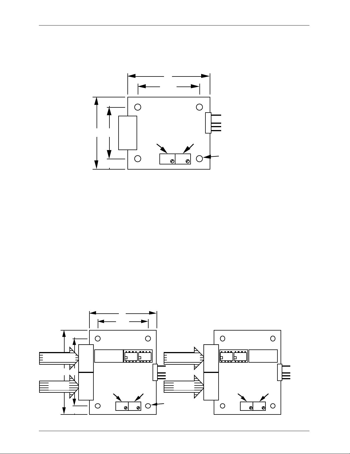
The single channel D/A converter gets it's data and power through a single 1/4 J-6 data cable. The
output is available on a 5 position molex connector on pins #1 and #3. Pin #2 is removed to be used
for a polarizing key if desired. If an external power supply is needed, it is attached to pins #4 and #5 of
the molex connector.
2"
1/4" 1/4"1 1/2"
1/4"
1
+ OUTPUT
- REFERENCE
- AUX. SUPPLY
5
3/4"
1 1/4"
1/4"
1/4
J-6
00H
Full ScaleMinimum Scale
FFH
If you need to optically isolate the analog output from the rest of the control system, cut the
1N4001 diode closest to the 1/4 J6 connecter and pin #1 of the 1/4 J6 connector (this is easiest to do
on the back of the J6 connector, rather than on the front). In this configuration you will need to use an
external power supply for the D/A.
A single channel D/A converter can be mounded by screwing it to where it is needed. Standoffs
should be used. A small card cage can be used when you need to hold a number of single D/A converters.
The Single Twelve Bit D/A converter is identical to the Eight Bit Single D/A converter except that its
twelve bit resolution gives it 4096 steps of resolution instead of 256. Twelve bit analog channels take one
and one half eight bit channels (twelve bits worth of data). The arrangement of the data within these
channels is as follows:
base Channel 00h (bits 0-3 = output 1’s lower 4 bits, bits 4-7 = output 2’s lower 4 bits)
base+01h Channel 01h (analog output #1 MSB)
base+02h Channel 02h (analog output #2 MSB)
base+03h Channel 03h (bits 0-3 = output 3’s lower 4 bits, bits 4-7 = output 4’s lower 4 bits)
base+04h Channel 04h (analog output #3 MSB)
base+05h Channel 05h (analog output #4 MSB)
+ AUX. SUPPLY
Mounting Holes
.156" dia. 4 places
2"
1/4" 1/4"1 1/2"
1/4"
Channel 00h
(bits 0-3 = output #1 LSB)
2 1/2" 2"
Channel 01h
(output #1 MSB)
1/4"
LSB
1/4
J-6
MSB
1/4
J-6
Move optoisolators
to use bits 0-3 or 4-7
Full ScaleMinimum Scale
LSB
1/4
J-6
MSB
1/4
1
5
Channel 00h
(bits 4-7 = output #2 LSB)
+ OUTPUT #1
- REFERENCE
- AUX. SUPPLY
+ AUX. SUPPLY
Channel 02h
(output #2 MSB)
J-6
Mounting Holes
FFH00H
.156" dia. 4 places
Move optoisolators
to use bits 0-3 or 4-7
bits 4-7 bits 0-3bits 4-7 bits 0-3
1
+ OUTPUT #2
- REFERENCE
- AUX. SUPPLY
5
+ AUX. SUPPL
Full ScaleMinimum Scale
FFH00H
2
Page 3

GILDERFLUKE & CO. ¥ 205 SOUTH FLOWER ST. ¥ BURBANK, CALIF. 91502-2102 ¥ 818/840-9484 ¥ FAX818/840-9485
- QUAD D/A and SERVO MOTOR CONTROLLER CONNECTIONS -
The quad D/A converters get their data and power through a single J-6 data cable. The analog output is available on a 1/4 J6/A analog output connection. The pin out for this connector is as follows:
Pin #1 GROUND
Pin #2 UNREGULATED 12 VDC (fused at 1 amp)
Pin #3 + CHANNEL 4 (03H) ANALOG OUTPUT
Pin #4 - CHANNEL 4 (03H) REFERENCE
Pin #5 + CHANNEL 3 (02H) ANALOG OUTPUT
Pin #6 - CHANNEL 3 (02H) REFERENCE
Pin #7 + CHANNEL 2 (01H) ANALOG OUTPUT
Pin #8 - CHANNEL 2 (01H) REFERENCE
Pin #9 + CHANNEL 1 (00H) ANALOG OUTPUT
Pin #10 - CHANNEL 1 (00H) REFERENCE
The GROUND and 12 VDC outputs are used to supply power to a Quad EFB (Electronic FeedBack)
servo controller when it is used with the Quad D/A. They can also be used to feed in 15 VDC from an
auxiliary power supply if needed. In most user applications, these two outputs won't be needed. The
negative reference outputs for all four channels are connected in common inside the Quad D/A. If your
application requires it, a single negative reference wire may used for all four channels.
If you are using servo motors, these are connected to the standard three pin sockets used by many
brands of servo motors. Some newer servo motors use a slightly different connector, and an adapter for
this style of connector is available from the servo motor manufacturers. The pin out for these servo
motor connections is as follows:
SIGNAL
SERVO
+ SUPPLY
SERVO
- SUPPLY
The last remaining connector is for attaching the power supply which is used to power the servo mo-
tors. The power for these must come from an external source as they can potentially use a lot more current than the animation system can normally supply. Most servo motors run from a voltage between 3.5
volts and 7.5 volts. The lower the voltage the less strength and speed a given servo motor will have. A
higher voltage will give that same servo motor greater speed and strength. In some cases a lower speed
is desired for the smoothness of the movement, while in other cases the need for high speed or strength
may be paramount. The chief disadvantages of running the servo motors in high voltage / high speed
applications are that the servo motor will run hotter and is much more likely to have a mechanical failure.
The size of the servo motor, the load it is driving, and the amount of movement it is doing can all ef-
fect the amount of current it will require. Most of the smaller servo motors draw about an amp of current
at stall (This is when the servo motor shaft is held against the motor's best efforts to move it.). This condition isn't often encountered in any real world applications, but if you are planning on really abusing your
servo motors you should allow about an amp per motor when selecting a power supply. Under most normal conditions, 1/4 to 1/2 an amp per servo motor will be sufficient. If your power supply is undersized,
you will see a certain amount of interaction between servo motors when a number of them are moving
at the same time.
To reduce the number of wires needed to run into a servo motor-controlled figure it is not uncom-
mon to run the high current power supply leads directly from the power supply to the servos in the figure
and gang the signal lines. When this is done, it is still necessary to run low current leads from the power
supply to the power supply connections on the quad D/A board. If the signal line runs to the servo motors are long, it may be necessary to use shielded lines to prevent noise and cross-talk between the servos. You can tell when you have this problem when some servo motors are tending to jitter uncontrollably.
3
Page 4

GILDERFLUKE & CO. ¥ 205 SOUTH FLOWER ST. ¥ BURBANK, CALIF. 91502-2102 ¥ 818/840-9484 ¥ FAX818/840-9485
5 5/16"
J-6 INPUT
4"
CHANNEL 1
(00H)
CHANNEL 2
(01H)
CHANNEL 3
(02H)
CHANNEL 4
(03H)
FULL
SCALE
MIN.
SCALE
FULL
SCALE
1/4 J-6A
OUTPUT
MIN.
SCALE
SERVO
MOTOR
POWER IN
FULL
SCALE
MIN.
SCALE
3210
SERVO
MOTOR
OUTPUTS
FULL
SCALE
MIN.
SCALE
Be aware that the servo motor input signals are notoriously bad travelers. They are susceptible to any
power supply noise, radio frequency (RF) interference, and even the noise from other servo motors. Try
to keep these lines as short as possible. Anything over 10 feet can cause problems. Even shorter lengths
can have problems under the right circumstances. Possible solutions include large capacitors across the
power supply leads and pullup resistors between the signal input and the positive supply line. These must
be located as close as possible to the servo motors.
If you need to optically isolate the analog outputs from the rest of the animation control system, you
will need to cut the four 1N4001 diodes D1 through D4 (the four diodes closest to the J6 connector)
and pins 1, 11, 21, and 31 on the J6 connector. This is easiest to do on the back of the J6 connector,
rather than on the front. You will need to use an external power supply for the Quad D/A when operating
in this mode. The four channels of the Quad D/A are not isolated from one another. If you need complete isolation between channels, you should use four single channel D/A converters with separate
power supplies for each.
The Quad D/A comes in a plastic case which can be mounted by simply double face taping it
where ever you need. If you need to mount it more solidly, then put screws through the back of the
case as needed. The front of the case can be removed for service and adjustment after the box has
been mounted.
4
Page 5

GILDERFLUKE & CO. ¥ 205 SOUTH FLOWER ST. ¥ BURBANK, CALIF. 91502-2102 ¥ 818/840-9484 ¥ FAX818/840-9485
- D/A CONVERTER ADJUSTMENTS -
Each channel of every D/A converter has two adjustments. One of these two sets the level of the
output when a minimum scale digital input (00H) is sent to the D/A, while the other sets the level of the
output when a full-scale (FFH) signal is sent to it. Both of these adjustments are completely independent
of one another. Moving one doesn't affect the other, although it does change the positions of all the
steps in between the two. Either of these setting may be adjusted to put it anywhere in the 0 to 10 VDC
output range. Adjusting the minimum scale level above that of the full scale level has the effect of 'reversing' the movement. By doing this the output can be set so that a full scale signal will be at a lower
voltage than a minimum scale signal. All D/A converters are factory calibrated to 0 to 10 VDC before
shipping.
To adjust the full and minimum scale outputs, you need to send either a full or minimum scale signal
to the D/A. This can come from a Micro Console, Full-sized Programming Console, Togglodyte,
Hand/Off/Auto (HOA) test switches, or a number of other sources. You then adjust the appropriate trimpot on the D/A board to set the desired level (Full scale trimpot if you are sending a full scale signal, minimum scale trimpot if you are sending a minimum scale signal). If you are setting the signal to a desired
voltage, measure the output voltage between the negative and positive output connector on the D/A
and adjust the trimpot until the signal is at the desired level. If you are adjusting the signal for setting the
end points of a mechanical movement or servo motor, you simply need to watch the movement and
adjust the trimpot until the movement is at the desired position.
When one end position is set, send the opposite full scale command to the D/A and adjust the ap-
propriate trimpot to set that end too.
Some caution must be used when adjusting servo motors or mechanical movements which may be
damaged by being commanded to go to a position beyond that which they are designed to move. In
these cases it is sometimes best to adjust both the full and minimum scale trimpots to a center position
for the movement and then adjust them slowly outward from there.
- ATCHLEY MFB CYLINDER ATTACHMENT -
An Atchley MFB actuator is a type of air cylinder which includes a jet pipe servo valve and
Mechanical FeedBack (i.e. MFB) system. It is used when there is a need for a strong, reliable, and simple
analog mechanical movement. The cylinder needs only be fed a 80 to 100 PSI supply of clean dry air
and a 0 to 10 VDC control signal. When given a 0 volt input, the cylinder will retract. When fed a 10
VDC signal, the cylinder will extend. If fed a 5 VDC signal, the cylinder will go to a mid-stroke position.
The MFB will follow a changing input voltage smoothly, reliably, and with a remarkable amount of
strength.
To connect an Atchley MFB actuator to a D/A converter, use the following to connect it's four wires:
ATCHLEY WIRES CONNECT TO:
RED ATTACH TO GREEN
GREEN ATTACH TO RED
YELLOW + OUTPUT FROM D/A
WHITE - REFERENCE FROM D/A
5
Page 6

GILDERFLUKE & CO. ¥ 205 SOUTH FLOWER ST. ¥ BURBANK, CALIF. 91502-2102 ¥ 818/840-9484 ¥ FAX818/840-9485
- TROUBLE SHOOTING -
If an analog movement is acting up and you suspect the D/A, the first thing to do is look at the LED
on each D/A channel. If it is not ramping up and down as smoothly as it should, then unplug the output.
If this fixes the problem, then the negative reference has most likely been attached to ground or some
other signal somewhere. If the LED is still uneven, then there is most likely one or more data lines feeding
the D/A with a bad connection. Check the cabling that feeds the data to the D/A. A Togglodyte or LED
Data Monitor can come in handy for this.
If the LED on the front doesn't change at all, even when the output cable has been disconnected,
then check that the fuse for that channel hasn't been blown in the animation system.
If the voltage measured on the output of a D/A changes appreciably when the output cable is dis-
connected, then there is a problem in the wires leading to whatever it is controlling, or in the controlled
device itself.
If the output randomly switches to a full on condition and stays there until you power the A/D down
(by powering down the whole system or just unplugging the D/A), this is a symptom of the output device
in the D/A receiving a electrical spike through the output cable. This is usually an indication of a problem
in the controlled device. If this problem persists, you may need to add spike protection to the D/A.
In most cases the D/A converters get the power they need from the J-6 data cables they are at-
tached to. In rare cases (as when they are attached at the end of long cables) the top end of the 0 to
10 volt swing may start to get lost. The symptom of this is the inability to get a full 10 VDC from the outputs. If your control signal doesn't need to go this high, then there is no problem. If it does then you will
need to add a supplemental power supply local to the D/A converter.
- OUTPUT SPECIFICATIONS -
The output capabilities of all D/A converters is as follows:
OUTPUT VOLTAGE: 0 TO 10 VDC
OUTPUT CURRENT: 0 TO 24 ma
OUTPUT DEVICE: LM324N
OUTPUT PROTECTION: OVERVOLTAGE/CURRENT PROTECTION
INHERENT TO LM324N
The capabilities of the servo motor outputs are as follows:
OUTPUT: OPEN COLLECTOR SWITCH TO GROUND
PULLUP: 4.7 K PULLUP TO + SERVO POWER SUPPLY
OUTPUT CURRENT: 16 ma MAXIMUM
OUTPUT/SERVO VOLTAGE: 5 VDC NOMINAL / 36 VDC MAXIMUM
6
 Loading...