

Page 1
GILDERFLUKE & CO. ¥ 205 SOUTH FLOWER ST. ¥ BURBANK, CALIF. 91502-2102 ¥ 818/840-9484 ¥ FAX818/840-9485
- INTELLIGENT PUBLIC ADDRESS SYSTEM -
February 27, 1999
The Intelligent Public Address System is used where a powerful and flexible zoned
Public Address System is needed. It can be used with our DR-300 and DR-400 Digital
Audio Repeater cards or in stand alone installations.
UP TO 256
DIGITAL
UP TO 256
PA STATIONS
EXT. INPUTS
REPEATER/
MIXER CARDS
Digital
Repeater/
Mixer Card
AMP
Printer Port
Analog Output
Serial Port
MA-100
PA Master
Local PA Outputs (8)
BGM input (1 or 8)
up to 31
MA-200
PA Interface Cards
EXT. INPUTSEXT. INPUTS
Repeater/
Mixer Card
BGM input (1 or 8)
Repeater/
Mixer Card
EXT. INPUTSEXT. INPUTS
EXT. INPUTSEXT. INPUTS
EXT. INPUTSEXT. INPUTS
Repeater/
Mixer Card
Repeater/
Mixer Card
Repeater/
Mixer Card
Repeater/
Mixer Card
Repeater/
Mixer Card
Digital
AMP
Digital
AMP
Digital
AMP
Digital
AMP
Digital
AMP
Digital
AMP
Digital
AMP
Local PA Outputs (8)
i of iii
Digital
Repeater/
Mixer Card
AMP
Page 2

GILDERFLUKE & CO. ¥ 205 SOUTH FLOWER ST. ¥ BURBANK, CALIF. 91502-2102 ¥ 818/840-9484 ¥ FAX818/840-9485
Intelligent PA System ........................................................................................................... 1
PA-100 One Button PA Stations ........................................................................................... 2
PA--400 Four Button PA Stations .......................................................................................... 2
Smart PA Stations ............................................................................................................... 3
Phantom PA Stations .......................................................................................................... 3
Serial Port Connections and Communications .............................................................. 5
Printer Port Connections and Communications ............................................................. 7
Intelligent PAÊSystem Software Configuration .............................................................. 10
PA Master ......................................................................................................................... 11
maximum number of stations ..................................................................................... 11
local PA ramp rate ..................................................................................................... 11
local BGM ramp rate .................................................................................................. 11
volume zone ramp rate .............................................................................................. 11
use printer handshake ................................................................................................ 11
console clock display ................................................................................................. 11
smart station clock ..................................................................................................... 11
set time ..................................................................................................................... 12
set date ..................................................................................................................... 12
allow zone stepping ................................................................................................... 12
Conditions to Print ...................................................................................................... 12
Conditions to Display ................................................................................................. 12
unmute on boot up ................................................................................................... 12
eXit ............................................................................................................................ 12
Volume Zone Limits .................................................................................................... 12
PA Stations ....................................................................................................................... 14
One Button PA Station ................................................................................................ 14
Four Button PA Station ................................................................................................ 14
latch buttons ....................................................................................................... 14
auto-release latched buttons ............................................................................... 14
Button Assignments .............................................................................................. 14
Select any PA Zone through the 16 trunk lines ................................................ 14
Directly access this PA stationÕs corresponding MA-100/200 output ................. 15
Mute a zone .................................................................................................. 15
Un-mute a zone ............................................................................................. 15
Half-mute a zone ........................................................................................... 15
Toggle mute zone .......................................................................................... 15
Toggle half-mute zone ................................................................................... 15
Rotate through mutes .................................................................................... 15
Set volume zone to minimum ......................................................................... 15
Set volume zone to maximum ........................................................................ 15
Lower volume zone output ............................................................................. 15
Raise volume zone output .............................................................................. 15
Alternate direction of volume zone output ...................................................... 15
microphone PTT ................................................................................................... 16
configure another Four Button station .................................................................. 16
eXit ...................................................................................................................... 16
Smart PAÊStation Configuration ........................................................................................ 17
PA station number ...................................................................................................... 19
baud rate .................................................................................................................. 19
PTT after keys .............................................................................................................. 19
display time ............................................................................................................... 19
busy PAs .................................................................................................................... 19
telephone mode ........................................................................................................ 19
debounce ................................................................................................................. 19
click enable ............................................................................................................... 19
ii of iii
Page 3

GILDERFLUKE & CO. ¥ 205 SOUTH FLOWER ST. ¥ BURBANK, CALIF. 91502-2102 ¥ 818/840-9484 ¥ FAX818/840-9485
beep length ............................................................................................................... 19
blab time ................................................................................................................... 20
entry time .................................................................................................................. 20
idle time .................................................................................................................... 20
auto release .............................................................................................................. 20
upload/download ....................................................................................................... 20
access lock ................................................................................................................ 20
microphone buttons .................................................................................................. 22
button ................................................................................................................. 22
locks used ............................................................................................................ 22
LCD string ............................................................................................................ 22
access type ......................................................................................................... 22
none ............................................................................................................. 22
Mute a zone .................................................................................................. 22
Un-mute a zone ............................................................................................. 22
Half-mute a zone ........................................................................................... 23
Toggle mute zone .......................................................................................... 23
Toggle half-mute zone ................................................................................... 23
Rotate through mutes .................................................................................... 23
Set volume zone to minimum ......................................................................... 23
Set volume zone to maximum ........................................................................ 23
Lower volume zone output ............................................................................. 23
Raise volume zone output .............................................................................. 23
Alternate direction of volume zone output ...................................................... 23
Repeater String .............................................................................................. 23
Terminal String ............................................................................................... 23
Printer String ................................................................................................... 24
Access a PA Zone .......................................................................................... 24
zone number ....................................................................................................... 24
aux. string ............................................................................................................ 24
zone entry column ............................................................................................... 24
vol. zone column ................................................................................................. 24
back to setup menu ............................................................................................. 24
string ................................................................................................................... 24
eXit ...................................................................................................................... 24
MA-100/200 Outputs ........................................................................................................ 25
respond to PA zone .................................................................................................... 25
normal audio volume level ......................................................................................... 25
audio level when half-muted ...................................................................................... 26
PA audio level ............................................................................................................ 26
use volume zone ....................................................................................................... 26
eXit ............................................................................................................................ 26
configure a different MA-100/200 Output ................................................................... 26
respond to mute zone ................................................................................................ 26
respond to half mute zone ......................................................................................... 26
Repeaters ........................................................................................................................ 27
Serial Port Commands ..................................................................................................... 28
Reload Default Configuration ..................................................................................... 28
Enter Configuration Mode .......................................................................................... 28
Configuration Dump .................................................................................................. 28
Load Configuration .................................................................................................... 29
Display Mutes ............................................................................................................. 29
Mute Masks ................................................................................................................ 29
Set Volume Zone ....................................................................................................... 29
Repeater Pass Through ............................................................................................... 29
Hardware Debug Mode .................................................................................................... 30
iii of iii
Page 4

GILDERFLUKE & CO. ¥ 205 SOUTH FLOWER ST. ¥ BURBANK, CALIF. 91502-2102 ¥ 818/840-9484 ¥ FAX818/840-9485
Connections ...................................................................................................................... 31
Terminal input .................................................................................................................. 31
Printer output ................................................................................................................... 31
PA Station Connections .................................................................................................... 31
PA Microphone Connections ............................................................................................ 31
Single Channel BGM Input ............................................................................................... 31
Eight Channel BGM Input ................................................................................................ 32
Eight Channel Local Outputs ............................................................................................ 32
Digital Data to Repeaters ................................................................................................. 33
Analog Output ................................................................................................................. 33
Power .............................................................................................................................. 34
PA Audio To Repeaters ..................................................................................................... 34
HEXadecimal to DECIMAL to PERCENTAGE ................................................................... 35
iv of iv
Page 5

GILDERFLUKE & CO. ¥ 205 SOUTH FLOWER ST. ¥ BURBANK, CALIF. 91502-2102 ¥ 818/840-9484 ¥ FAX818/840-9485
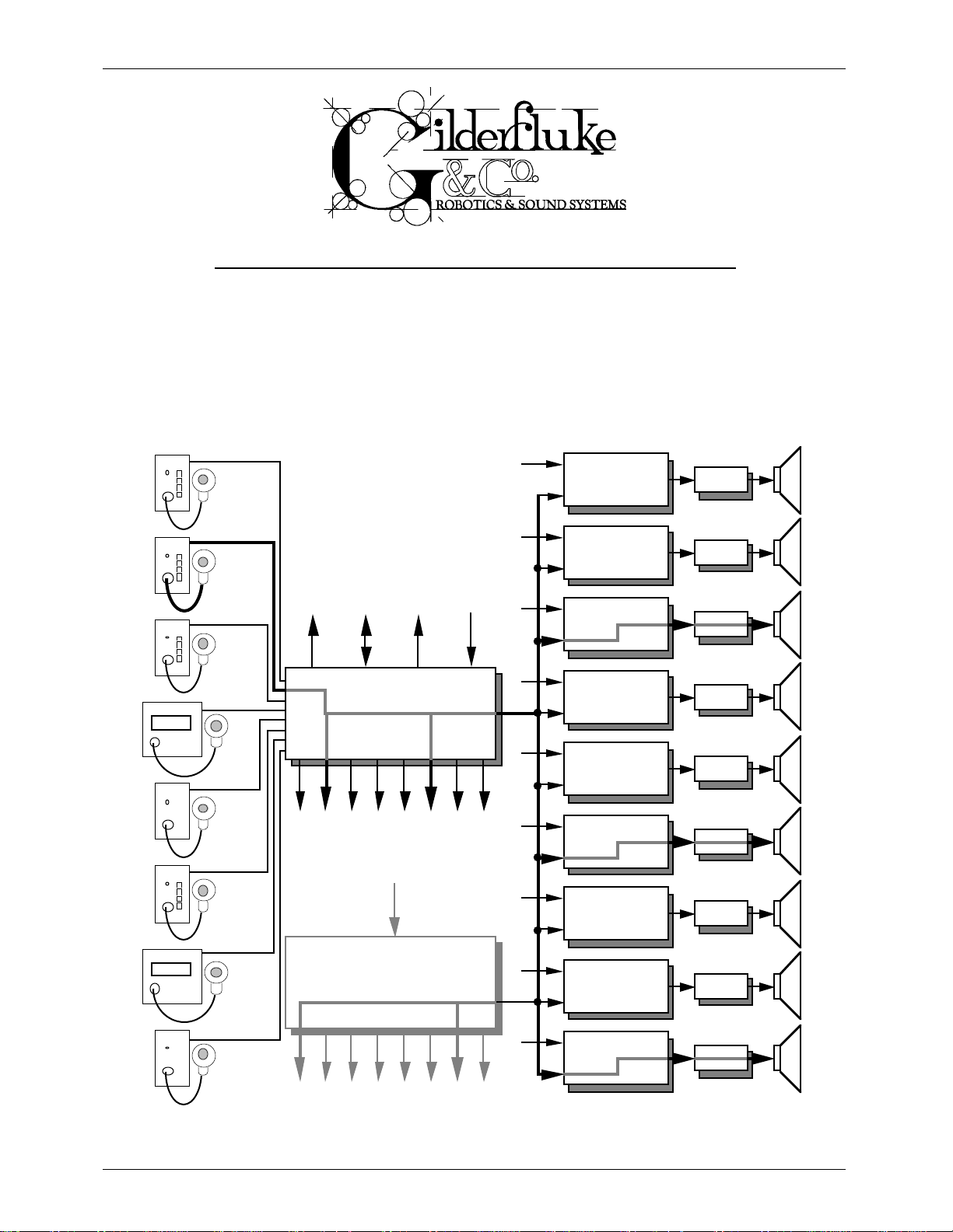
The Intelligent PA System consists of:
¥ One MA-100 PA Master to control the system and the first eight PA Stations and MA-100/200
Outputs.
¥ One MA-200 for each additional eight PA Stations or MA-100/200 Outputs needed.
¥ Any combination of up to 256 PA Stations
¥ Optionally, any combination of DR-300 or DR-400 Digital Audio Repeater / Mixer cards.
Unlike the hardwired PA systems you may have encountered in the past, in the Intelligent PA System
a ÔPA ZoneÕ is an absolutely arbitrary number. Any PA Station can generate requests for any PA Zone
number. Any output can respond to any of up to 19 different PA Zone numbers. Since any number of
outputs can respond to any individual PA Zone number, a global PA Zone can be set up by simply telling
every output in the system to respond to the same number.
As shown by the darkened audio path in the previous illustration, when a user at any PA Station requests a PA Zone, an audio path is opened to any of the MA-100/200 Outputs and Digital Audio
Repeater / Mixer cards in the system which have been configured to respond to requests for that PA
Zone (in the example on page one there are three DR-300 or DR-400 cards and four MA-100/200
Outputs responding). The normal audio on those outputs is dropped to a half muted level while the
audio from the PA Station is routed to them. All other parts of the PA System and the Repeaters on the
affected DR-300 cards continue to operate normally. With sixteen trunk lines, up to sixteen such ÔcrosszoneÕ PA announcements can go on at the same time.
There are 255 possible PA Zone numbers (00 through FE). The DR-300 and DR-400 Digital Audio
Repeater / Mixer cards can be configured to respond to as many as eight different PA Zone numbers.
Eight MA-100/200 Outputs are available from each MA-100 or MA-200 card. Each of these outputs
normally carries whatever audio is being fed into the ÔBack Ground Music (BGMÕ) input(s) on the back of
the unit. When a request for a PA zone comes in from any of the PA Stations, the BGM level on any of
the responding MA-100/200 Outputs is dropped to a half-muted level and the PA audio is mixed into the
output. Each MA-100/200 Output can be told to respond to up to nineteen different PA zone requests.
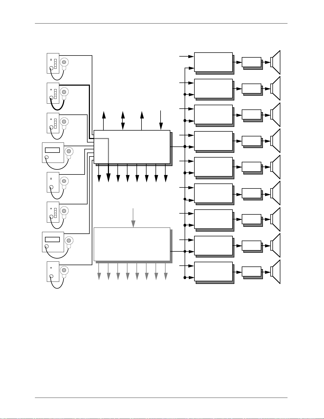
If a PA Station requests zone FF, a special high priority ÔLocal PA MODEÕ is selected. This opens up a direct connection between a PA Station and itÕs corresponding Local Output (as shown in the illustration
on the following page). This bypasses all 16 trunk lines. Up to 256 such ÔlocalÕ PA announcements (one
for each station) can go on at the same time. These will take precedence over any other type of announcement.
Because the PA system can be used for safety announcements, a number of different priority options are available. The Digital Audio Repeater / Mixer cards each have one PA Station each assigned as
top and second priority. These are assigned individually for each Digital Audio Repeater / Mixer card.
Valid PA requests from the second priority PA Station override all other PA requests except those from the
top PA Station. These priority PA Stations will usually be assigned to the station from which safety announcements are normally made, and to the PA Station located closest to the emergency exit for the
area covered by the speakers attached to that particular Digital Audio Repeater / Mixer card.
If no other PA priority options are used, then the DR-300 and DR-400 cards treat all other PA requests
equally. If two valid PA requests come in to the same Repeater card, then both are honored and the
audio from both are mixed equally. The STANDARD PRIORITY OPTION allows you to give PA Stations with
higher number assignments priority over those with lower numbers. The ZONE PRIORITY OPTION allows PA
Zone requests for higher numbered PA Zones to take priority over those for lower numbered PA Zones.
The MA-100/200 Outputs' priorities are set by the order in which you enter the PA zones they will respond to. The first entry has the highest priority. Any Local Mode PA requests always take priority over all
other PA zone requests.
1 of 35
Page 6
GILDERFLUKE & CO. ¥ 205 SOUTH FLOWER ST. ¥ BURBANK, CALIF. 91502-2102 ¥ 818/840-9484 ¥ FAX818/840-9485
UP TO 256
DIGITAL
UP TO 256
PA STATIONS
EXT. INPUTS
EXT. INPUTSEXT. INPUTS
REPEATER/
MIXER CARDS
Digital
Repeater/
Mixer Card
Digital
Repeater/
Mixer Card
AMP
AMP
Printer Port
Serial Port
Analog Output
MA-100
PA Master
Local PA Outputs (8)
BGM input (1 or 8)
up to 31
MA-200
PA Interface Cards
BGM input (1 or 8)
EXT. INPUTSEXT. INPUTS
EXT. INPUTSEXT. INPUTS
EXT. INPUTSEXT. INPUTS
Digital
Repeater/
Mixer Card
Digital
Repeater/
Mixer Card
Digital
Repeater/
Mixer Card
Digital
Repeater/
Mixer Card
Digital
Repeater/
Mixer Card
Digital
Repeater/
Mixer Card
AMP
AMP
AMP
AMP
AMP
AMP
Digital
Repeater/
Mixer Card
AMP
Local PA Outputs (8)
Any mix of up to 256 PA Stations can be attached to the PA System at the same time. The PA stations
are available in four different styles:
1) PA-100 One Button PA Stations: These use the microphoneÕs Push To Talk (PTT) button to select any one PA zone. All mounting, wiring, and microphone details are identical to those for
the Four Button PA Stations.
2) PA--400 Four Button PA Stations can select any of four different PA zones, plus one more with
the microphoneÕs PTT button. Their buttons can be configured as push-to-talk buttons or to
latch the last requested zone (the PA channel wonÕt be opened until the microphone PTT
button is depressed). When operating in this latter mode, you can tell the stationÕs microphone PTT button to revert to the PA zone it normally accesses when it is released.
Both PA-100 and PA-400 PA Stations mount in standard deep duplex boxes. All power and
signals are attached to them through a standard RJ-45 (8 pin modular) style connector.
A low impedance noise canceling microphone like the University Sound US602FL is typi-
cally used with PA-100 and PA-400 stations. A four pin male ÔXLRÕ is used to attach the micro-
2 of 35
Page 7

GILDERFLUKE & CO. ¥ 205 SOUTH FLOWER ST. ¥ BURBANK, CALIF. 91502-2102 ¥ 818/840-9484 ¥ FAX818/840-9485
phone to the PA stations. The pin out is as follows:
1) Microphone
2) Microphone
3) Push To Talk (PTT) switch
4) Push To Talk (PTT) switch
The microphone gain control on each of these stations is used to adjust for individual microphones used with the system. It should be set to where normal audio levels are not
clipped on the outputs.
The buttons on the face of any four button PA stations can also be configured to mute
any full or half mute zone or raise or lower the volume of any volume control zone.
3) The Smart PA Stations can be set up to access all of the features in the entire audio system,
including any Digital Audio Repeaters, Animation Control Systems, and volume control zones
which happen to be attached to it. They are available with backlit LCD displays on them. Up
to 18 pushbuttons are normally located on the microphone. Any button can be configured
to request any mute or half-mute zone, send commands to one or more Digital Audio
Repeaters, or ramp the volume of any volume control zone up or down. For those PA
Stations which need access to more features than this number of buttons would allow, a
numeric-style entry is used to give them access to any features which you have enabled.
4) The Phantom PA Stations are used for automated announcements and automated 'emergency' spiels. In this application, instead of having a microphone attached to it, the
Phantom PA Station uses the output of one of the Digital Audio Repeater / Mixer cards (or
other source) as its input. This card is usually configured in the 'loop while' mode so that it will
loop as long as the start input is active. The enabling input for the Phantom PA Station comes
from the 'running status' output of this Digital Audio Repeater / Mixer card. When the
Repeater with the automated spiel on it is started by a switch closure on its start input, it automatically selects the required PA Zone through the Phantom PA Station. The spiel will continue until the enabling signal is released and the spiel has finished. In emergency spiel applications, you may want to assign the Phantom PA Station a fairly low priority so that a live
person giving useful information can easily 'step' on the canned spiel. If the audio system is
being controlled by a serial data link from another computer or control system, serial commands can be used to select and start canned spiels and route them to the desired PA
Zones.
Messages which are recorded for use with the Phantom PA Stations should allow a second or two at their starts to allow time for the BGM volume levels to ramp down as the PA announcement levels ramp up. The actual amount delay needed depends on the ramp rates
you have set in the PA Master.
The wiring needed by any PA Station is a single eight conductor modular style telephone cable. This
will normally provide all the power, communications, and audio signals to the PA Station. On some
longer runs (greater than 2500 feet), it may be necessary to add a local power supply to some PA
Stations. If absolute silence is required on the PA audio channel, then a shielded twisted pair is recommended for the microphone line.
All wires between the PA Stations and the MA-100 or MA-200 panels are transformer or opto-isolated.
MOV varistors can be used between each of the wires and chassis (earth) ground to provide lightning
protection if needed. Facing the end of the cable with the release latch upwards, its pin out is as follows:
3 of 35
Page 8

GILDERFLUKE & CO. ¥ 205 SOUTH FLOWER ST. ¥ BURBANK, CALIF. 91502-2102 ¥ 818/840-9484 ¥ FAX818/840-9485
COLOR Signal NAME:
LEFT Gray + RS-422 Serial Data
Orange - RS-422 Serial Data
Black + 27 to 35 VDC Supply
Red Supply Ground
Green Supply Ground
Yellow + 27 to 35 VDC Supply
Blue Balanced Audio Signal
RIGHT Brown Balanced Audio Signal
If you are using manufactured cables, make sure that the signals are not ÔflippedÕ from end to end.
The color code above must read the same at both ends of any cable. Connectors are commercially
available for combining up to six of these signals into a single 50 conductor telephone cable.
The MA-100 must be linked to all MA-200s in a PA System by two ribbon cables. One of these is 40
conductors. The other is 50 Conductors. The maximum length between the MA-100 and the furthest MA200 should be under 10 feet.
4 of 35
Page 9

GILDERFLUKE & CO. ¥ 205 SOUTH FLOWER ST. ¥ BURBANK, CALIF. 91502-2102 ¥ 818/840-9484 ¥ FAX818/840-9485
Serial Port Connections and Communications:
The Intelligent PA System is communicated with a serial data line from your computer, terminal, or
control system. As the master for the audio system, it acts a a bridge for all communications with all
Digital Audio Repeaters, Smart Brick Systems, and anything else attached to it.
All characters are sent to the PA System in standard ASCII. All numeric values are sent in
HEXadecimal (HEX for short), and consist of one or more ASCII characters (0-9, A through F). The case
(as in upper and lower) of all input is important. A lower case 'a' signifies a command, while an 'A' is a
numeric value. If the PA System receives another command while it is waiting for additional input needed to complete the previous command, it will abandon the previous command and start working on the
new one.
In the following documentation any input you will send to the audio system is shown in outline. The
response to a command is shown in italics.
If the PA System is in a mode where you expect to receive some response from it, you must wait to
receive all of the characters you are expecting before sending the system a new command. The reason
for this is that you are potentially talking to hundreds of microprocessors at a time, and if you issue a
command which gives a response from one, and then a command which gives a response from a another before the first has finished, then the two may try to output data at the same time. This won't
cause any damage, but may result in garbled data at the receiver.
It is also possible to overload the PA System with too many commands through the serial port. You
don't want to take too much time away from it to service the serial port.
To communicate with the PA System through the serial port, you can use just about any computer or
terminal which has a serial port on it. Some newer computer designs, like the Apple Macintosh, come
with serial ports which are directly compatible with the RS-422 / RS-485 signal levels the PA System wants
to see. These signal levels are close enough to be used with the RS-232 signal levels found on most
older computers (like most IBM compatibles) with only a simple adapter cable, so long as the wire isn't
too long. To gain the full advantage of the RS-422 / RS-485 signal levels you will need to use a signal
level adapter.
If you are using a computer as a terminal you will need to run a modem or terminal emulation program. These will send everything you type on the keyboard out the serial port on your computer while
printing on the screen anything which comes in from the audio system through the serial port. A modem
program will usually have the advantage over a terminal emulation program in that it will allow you to
save data to your computer's disk drives and then send it back to the audio system at a later date. The
PA System uses no screen control codes or <ESC>ape sequences, so it should work on any machine
with a 80 column by 24 line display. Machines with other display formats will work, but may not look so
neat on the screen.
When configuring your modem program, you should set it for 9600 baud, 8 data bits, one stop bit,
and no parity. You must set your program not to insert an extra LineFeed (LF) character after each
Carriage Return (CR) it receives.
If you have hooked up the PA System to your computer and it still doesnÕt seem to respond to the
keyboard, the first thing to check is that you are attached to the right serial port on the PC. The easiest
way to do this is to disconnect the PA System and short between the Tx data out and Rx data in pins on
the serial port connector on the back of your computer. On all IBMs and compatibles this means sticking
a paper clip or similar object between pins 2 and 3 on the ÔCom.Õ connector. While still running the
modem program, anything you type should be shown on the screen while this paper clip is in place,
while nothing will appear when you remove it. If your computer passes this test, then you are using the
right serial port and the problem is most likely the baud rate setting or in your wiring to the PA System. If
you get characters on the screen even with the paper clip removed from the serial port, it means you
probably need to set the ÔechoÕ mode to ÔnoneÕ or Ôfull duplexÕ and try this test again.
The serial data signals from the PA System are brought out on the connector labeled 'TERMINAL
Input'. This is a 6 position RJ-11 (modular telephone style connector). Facing the end of the cable with
the release latch upwards, its pin out is as follows:
5 of 35
Page 10

GILDERFLUKE & CO. ¥ 205 SOUTH FLOWER ST. ¥ BURBANK, CALIF. 91502-2102 ¥ 818/840-9484 ¥ FAX818/840-9485
COLOR Signal NAME:
LEFT White Signal Ground
Black - Serial Data OUT FROM PA SYSTEM
Red + Serial Data OUT FROM PA SYSTEM
Green - Serial Data IN to PA SYSTEM
Yellow + Serial Data IN to PA SYSTEM
RIGHT Blue Signal Ground
To cross wire the RS-422 / RS-485 signals from the PA System to the RS-232 serial port of an IBM compatible, cross connect the signals as follows:
DB-25 DE-9 Signal Signal FROM/TO Audio SYSTEM
2 3 Data OUT - Serial Data IN to Repeaters (Green)
3 2 Data IN - Serial Data OUT FROM Repeater (Black)
7 5 Ground Signal Ground (Blue or White)
Apple Macintosh computers have true RS-422 serial ports built in. To connect to the PA System, the
pin out is as follows (view is of connector on the outside of a Macintosh):
from + serial data out from repeaters (red)
from - serial data out from repeaters (black)
The PA System expects to see the serial data in the following format
678
345
12
to + serial data in to repeaters (yellow)
to - serial data in to repeaters (green)
signal ground (white or blue)
ONE START BIT
EIGHT Data BITS
ONE or TWO STOP BITS
If the odd parity is enabled, then the data appears in the following format:
ONE START BIT
SEVEN Data BITS
ODD PARITY BIT
ONE or TWO STOP BITS
When the parity is enabled, any data with a parity error in it is simply ignored.
6 of 35
Page 11

GILDERFLUKE & CO. ¥ 205 SOUTH FLOWER ST. ¥ BURBANK, CALIF. 91502-2102 ¥ 818/840-9484 ¥ FAX818/840-9485
Printer Port Connections and Communications:
The Intelligent PA System supports a single ÔPRINTER OutputÕ port. This can be attached to a printer or
CRT to log selected PA System activity. Connections to this serial port are similar to those used for the
TERMINAL Input port, except that instead of a data input line the printer port supports only a handshaking
line.
The Printer Output is also 6 position RJ-11 (modular telephone style connector). Facing the end of
the cable with the release latch upwards, its pin out is as follows:
COLOR Signal NAME:
LEFT White Signal Ground
Black - Serial Data OUT FROM PA SYSTEM
Red + Serial Data OUT FROM PA SYSTEM
Green - Clear to Send IN to PA SYSTEM
Yellow + Clear to Send IN to PA SYSTEM
RIGHT Blue Signal Ground
The printer port is set for 9600 baud, 8 bits of data, 1 stop bit, no parity.
7 of 35
Page 12

GILDERFLUKE & CO. ¥ 205 SOUTH FLOWER ST. ¥ BURBANK, CALIF. 91502-2102 ¥ 818/840-9484 ¥ FAX818/840-9485
INTELLIGENT PA SYSTEM HARDWARE CONFIGURATION:
Each MA-200, including the one inside the MA-100, must be addressed before it is connected and
turned on. A 5 position dipswitch or a rotary switch (plus a 2 position dipswitch) on the back of each unit
is used to set which address the PA stations and Local Outputs on each MA-200 will respond to. With up
to 32 MA-200Õs attached to the system, the following are all of the possible settings for these switches:
MA-100 PA Station
or and
MA-200 5 4 3 2 1 Rotary Sw1 MA-100/200 Outputs
1 ononononon 0 00 through 07
2 on on on on open 0 08 through 0F
3 on on on open on 1 10 through 17
4 on on on open open 1 18 through 1F
5 on on open on on 2 20 through 27
6 on on open on open 2 28 through 2F
7 on on open open on 3 30 through 37
8 on on open open open 3 38 through 3F
9 on open on on on 4 40 through 47
10 on open on on open 4 48 through 4F
11 on open on open on 5 50 through 57
12 on open on open open 5 58 through 5F
13 on open open on on 6 60 through 67
14 on open open on open 6 68 through 6F
15 on open open open on 7 70 through 77
16 on open open open open 7 78 through 7F
17 open on on on on 8 80 through 87
18 open on on on open 8 88 through 8F
19 open on on open on 9 90 through 97
20 open on on open open 9 98 through 9F
21 open on open on on A A0 through A7
22 open on open on open A A8 through AF
23 open on open open on B B0 through B7
24 open on open open open B B8 through BF
25 open open on on on C C0 through C7
26 open open on on open C C8 through CF
27 open open on open on D D0 through D7
28 open open on open open D D8 through DF
29 open open open on on E E0 through E7
30 open open open on open E E8 through EF
31 open open open open on F F0 through F7
32 open open open open open F F8 through FF
The ÔOPENÕ position on each switch is towards the top of the case.
The MA-100 is usually addressed as #1, but can be set for any address desired so long as it doesnÕt
conflict with any MA-200.
The four serial ports on the MA-100 can each be configured to different baud rates using wire wrap
1
With the MA-100/200s with the address set with a rotary switch, the #2 dipswitch is set as shown for
the #1 switch column.
8 of 35
Page 13

GILDERFLUKE & CO. ¥ 205 SOUTH FLOWER ST. ¥ BURBANK, CALIF. 91502-2102 ¥ 818/840-9484 ¥ FAX818/840-9485
jumpers inside. All but the PA Station port are usually configured for 9600 Baud. The PA stations have
been installed running at rates as high as 38.4 KBaud. Long wire runs through existing wiring at some installations havenÕt been able to support this high of a rate. For this reason we have generally been shipping PA Stations and MA-100Õs set for 9600 Baud.
Four Button PA stations and Smart PA Stations must have their Baud rates set to match those of the
MA-100 or they wonÕt be able to talk. The Four Button Stations are set using jumpers. See the Smart PA
Station configuration for instructions on setting their Baud rates. The following shows how to set the Baud
rates on Four Button PA Stations and the MA-100s:
PA Port
Repeater Port
10
11
9
clk0
clk0/
ckl1
4060
3
75 Baud
Q14
2
Q13
150 Baud
1
Q12
300 Baud
15
Q10
1200 Baud
13
Q9
2400 Baud
14
Q8
4800 Baud
6
Q7
4
Q6
5
Q5
7
Q4
R
12
9600 baud
19.2KBaud
38.4KBaud
76.8KBaud
MA -100 Baud Rat e Jumper
Printer Port
Terminal Port
10
11
9
clk0
clk0/
ckl1
4060
3
Q9
Q8
Q7
Q6
Q5
Q4
150 Baud
2
300 Baud
1
600 Baud
15
2400 Baud
13
4800 Baud
6
4
5
7
1
2
314
4
5
Output
38.4 KBaud
9600 Baud
76.8 KBaud
19.2 KBaud
Q14
Q13
Q12
Q10
R
12
Fo u r Butt o n P A St a tion Baud Ra te J ump er
9 of 35
Page 14

GILDERFLUKE & CO. ¥ 205 SOUTH FLOWER ST. ¥ BURBANK, CALIF. 91502-2102 ¥ 818/840-9484 ¥ FAX818/840-9485
Intelligent PAÊSystem Software Configuration :
The software configuration mode is entered by the command:
"m" (5AA5)
The ÒmÓ is the command. The (5AA5) which follows is a key to keep this mode from being inadvertently entered. As with the serial commands, the upper and lower 'case' of all input is important. An 'a' is a
command while an 'A' is a number. All numeric values are entered in HEX (0 - 9, A - F).
If another command is entered while the last command is waiting for additional input, the new command will be started. If at any point you enter a command in error and it is waiting for additional input,
you can leave the command by entering an <ESC>ape key. This will leave the original configuration
unaltered.
If you want to keep a hard copy printout of the current configuration setting, you should use the
<ESC>ape key to redraw the screen while saving the print in the modem program running on your
computer. This file can then be printed out at any time.
This Ôm5AA5Õ command will bring up the following ÔfirstÕ menu:
-Gilderfluke & Co. Intelligent Public Address System - ver 1.06 - c1990-92 DCM-
Would you like to configure.....
m) MA-100 PA Master
p) PA stations
z) MA-100/200 outputs
r) Repeaters
X) eXit
Enter command-
This menu is used to access the other menus inside the PA Master. (If you select the Repeaters or
Smart PA Station setups, the menus actually come from the controlled devices.) These menu selections
are used as follows:
10 of 35
Page 15

GILDERFLUKE & CO. ¥ 205 SOUTH FLOWER ST. ¥ BURBANK, CALIF. 91502-2102 ¥ 818/840-9484 ¥ FAX818/840-9485
¥¥¥¥¥¥¥¥¥¥¥¥¥¥¥¥¥¥¥¥¥¥¥¥¥¥¥¥¥¥¥¥¥¥¥¥¥¥¥¥¥¥¥¥¥¥¥¥¥¥¥¥¥¥¥¥¥¥¥¥¥¥¥¥¥¥¥¥¥¥¥¥¥¥¥¥¥¥¥¥¥¥¥¥¥¥¥¥¥¥¥¥¥¥¥
m) PA Master:
Used to set up the few ÔglobalÕ variables used in the system. These are:
-Gilderfluke & Co. Intelligent Public Address System - ver 1.06 - c1990-92 DCM-
- Public Address Master Setup -
a) maximum number of stations- 00 | p) print all errors- yes
b) local PA ramp rate- 10 | q) print all openings- yes
c) local BGM ramp rate- 10 | r) print all closings- no
d) volume zone ramp rate- 10 | s) print all others- yes
e) use printer handshake- yes | t) display all errors- yes
f) console clock display- yes | u) display all openings- yes
g) smart station clock- yes | v) display all closings- no
h) set time | w) display all others- yes
i) set date | z) unmute on bootup- yes
j) allow zone stepping- no | x) eXit
G) volume zone #1 maximum limit- FF | O) volume zone #1 minimum limit- 00
H) volume zone #2 maximum limit- FF | P) volume zone #2 minimum limit- 00
I) volume zone #3 maximum limit- FF | Q) volume zone #3 minimum limit- 00
J) volume zone #4 maximum limit- FF | R) volume zone #4 minimum limit- 00
K) volume zone #5 maximum limit- FF | S) volume zone #5 minimum limit- 00
L) volume zone #6 maximum limit- FF | T) volume zone #6 minimum limit- 00
M) volume zone #7 maximum limit- FF | U) volume zone #7 minimum limit- 00
N) volume zone #8 maximum limit- FF | V) volume zone #8 minimum limit- 00
Enter command-
a) maximum number of stations:
This allows you to set the number of PA stations the system will scan for. As it runs damn
fast even when all 256 stations are being scanned, it is generally left at a setting of 00.
b) local PA ramp rate:
c) local BGM ramp rate:
These are used to set the speed at which the microphone and BGM inputs are ramped
on the MA-100/200 outputs. This does not affect the speed of any ramps on any DR-300 or
DR-400 cards attached to the system. Lower numbers give slower ramp rates. These are adjusted to your tastes. If the PA ramp rate is too high, then the microphone switch ÔclickÕ will be
more pronounced. If it is too low, then it will take a while for the microphone to cut in, which
may cut off the first part of an announcement. Values of Ô10Õ are typically used when ÔaÕ
above is set to Ô00Õ.
d) volume zone ramp rate:
When ramping a volume zone up or down from any PA station, this control sets the
speed at which the ramping will take place. A value of 01 will give you the fastest rate, while
a value of FF will be the slowest.
e) use printer handshake:
This toggle allows you to set whether or not the printer port will listen to the handshaking
input. If it is toggled ÔoffÕ, then the PA Master will expect your printer to be able to keep up
with whatever it sends down the line.
f) console clock display:
This toggle turns on and off the clock display on the terminal (if any) attached to the system.
g) smart station clock:
This toggle turns on and off the clock display on any Smart PA stations attached to the PA
System. If the Smart StationsÕ clocks are enabled here, they can also be disabled or enabled
on each individual station as well. Leaving this toggle on, even if no Smart PA Stations are at-
11 of 35
Page 16

GILDERFLUKE & CO. ¥ 205 SOUTH FLOWER ST. ¥ BURBANK, CALIF. 91502-2102 ¥ 818/840-9484 ¥ FAX818/840-9485
tached to the system, will only slow down the system operation slightly. When this toggle is
ÔONÕ, you will see the LEDs on the front of all the dumb PA Stations flash once each second
as the clocks are updated.
h) set time:
i) set date:
These do pretty much what you would expect them to do. Other than time stamping,
the clock and calendar arenÕt used for anything in the system. The seconds are reset to zero
when you enter the minutes.
j) allow zone stepping:
This toggle when ÔONÕ will not allow any dumb PA stations to open any PA zone which is
currently being used by any other PA station. If enabled, this will also generate an error message on the terminal and printer output from the MA-100 PA Master. Smart PA Stations can
individually enable or disable their ability to step on zones which are being used by other PA
stations.
Conditions to Print:
p) print all errors:
q) print all openings:
r) print all closings:
s) print all others:
Conditions to Display
t) display all errors:
u) display all openings:
v) display all closings:
w) display all others:
These toggles control how much data will be sent to the printer or terminal. The various
messages are defined as follows:
1) errors = any trouble messages from the PA master or PA Stations.
2) openings = any PA zone or local request has been received.
3) closings = any PA zone or local request has been released.
4) others = volume zone, mute zone, or any other special request from the PA stations.
z) unmute on boot up:
When this toggle is on, all volume zones will be set to their maximum levels and all mute
zones will be cleared when ever the MA-100 resets.
x) eXit:
This returns you to the first menu.
G) volume zone #1 maximum limit:
H) volume zone #2 maximum limit:
I) volume zone #3 maximum limit:
J) volume zone #4 maximum limit:
K) volume zone #5 maximum limit:
L) volume zone #6 maximum limit:
M) volume zone #7 maximum limit:
N) volume zone #8 maximum limit:
O) volume zone #1 minimum limit:
P) volume zone #2 minimum limit:
Q) volume zone #3 minimum limit:
R) volume zone #4 minimum limit:
S) volume zone #5 minimum limit:
T) volume zone #6 minimum limit:
U) volume zone #7 minimum limit:
V) volume zone #8 minimum limit:
Volume Zone Limits: These commands allow you to limit the range of adjustment for the
eight analog VOLUME CONTROL outputs when adjusted from a PA Station. This allows you to
12 of 35
Page 17

GILDERFLUKE & CO. ¥ 205 SOUTH FLOWER ST. ¥ BURBANK, CALIF. 91502-2102 ¥ 818/840-9484 ¥ FAX818/840-9485
set artificial limits as to how far a user at a PA station can adjust any of the volume control
outputs.
13 of 35
Page 18

GILDERFLUKE & CO. ¥ 205 SOUTH FLOWER ST. ¥ BURBANK, CALIF. 91502-2102 ¥ 818/840-9484 ¥ FAX818/840-9485
¥¥¥¥¥¥¥¥¥¥¥¥¥¥¥¥¥¥¥¥¥¥¥¥¥¥¥¥¥¥¥¥¥¥¥¥¥¥¥¥¥¥¥¥¥¥¥¥¥¥¥¥¥¥¥¥¥¥¥¥¥¥¥¥¥¥¥¥¥¥¥¥¥¥¥¥¥¥¥¥¥¥¥¥¥¥¥¥¥¥¥¥¥¥¥
p) PA Stations:
This command is used to set up the PA Stations used in the system. It will first ask you which PA Station
you would like to configure (00 to FF). After this it will ask what type of PA Station it is connected to this
port. If it is a One Button PA Station, it will just ask the zone number you would like this station to access
(00 to FE, or FF for Local Mode) and then return to the first menu. If it is a Smart PA Station, it will bring up
the menu from the Smart PA Station you asked for. If it is a Four Button PA Station, it will bring up the following menu:
-Gilderfluke & Co. Intelligent Public Address System - ver 1.06 - c1990-92 DCM-
- Four Button PA Station Setup station number 02
a) latch buttons- no
b) auto-release latched buttons- no
c) latch buttons- no
d) button #1 accesses PA zone- 01
e) button #2 accesses PA zone- 02
f) button #3 accesses PA zone- 03
g) button #4 accesses PA zone- 00
h) microphone PTT accesses MA-100/200 output 02
z) configure another Four Button station
x) eXit
Enter command-
a) latch buttons:
A Four Button PA Station can normally access five different PA Zones. If this toggle is ÔoffÕ,
the four buttons on the front of the station to act as additional PTT (Push-To-Talk) buttons just
like the one on the microphone. If this toggle is turned ÔonÕ, whatever button the user last
pushed will be accessed every time the microphone PTT (Push-To-Talk) button is pressed. This
option has the disadvantage of loosing the microphone PTT buttonÕs normal function.
b) auto-release latched buttons:
If this and the previous function are both turned ÔonÕ, any front panel buttons will be
latched until the PTT button is pushed, and then revert back to its normal function as soon as
it is released. In this way you can still have access to all five PA Zones from a Four Button PA
Station.
Button Assignments:
c) button #1:
d) button #2:
e) button #3:
f) button #4:
These commands are used to select what action will take place on each of the four buttons on a four Button PA station. The options are:
a) Select any PA Zone through the 16 trunk lines. These can be numbered from 00 to FE.
Any MA-100/200 or DR-300/400 can respond to these zone requests. Entering a value of
ÔFFÕ will request this PA stationÕs corresponding MA-100/200 output for direct access (the
next command is a little easier way of performing this same function).
14 of 35
Page 19

GILDERFLUKE & CO. ¥ 205 SOUTH FLOWER ST. ¥ BURBANK, CALIF. 91502-2102 ¥ 818/840-9484 ¥ FAX818/840-9485
b) Directly access this PA stationÕs corresponding MA-100/200 output. This type of ac-
cess does not use any of the trunk lines, so up to 256 of them (one for each PA station)
can be used simultaneously. Selecting this command has the same effect as using the
ÔaÕ command above, and then entering a value of ÔFFÕ.
c) Mute a zone. Any of the eight possible mute zones can be activated by a button which
has this function enabled. Any MA-100/200 output or DR-100/300/400 which has been
configured to respond to the requested mute zone will be muted. A full mute will take
precedence over any half mutes active on the same outputs.
d) Un-mute a zone. This command will configure this button to remove both full and half
mutes from the selected zone when it is pressed. Any MA-100/200 output or DR100/300/400 which has been muted or half muted by this zone will have itÕs audio returned to itÕs normal audio level.
e) Half-mute a zone. Any of the eight possible half-mute zones can be activated by a but-
ton which has this function enabled. Any MA-100/200 output or DR-300/400 which has
been configured to respond to the requested half-mute zone will have itÕs audio level
lowered to whatever has been set as the half-muted level. A full mute will take precedence over any half mutes active on the same outputs.
f) Toggle mute zone. This command will configure this button to toggle on and off the se-
lected mute zone each time it is pushed. Any MA-100/200 output or DR-100/300/400
which has been configured to respond to the requested mute zone will be muted. A full
mute will take precedence over any half mutes active on the same outputs.
g) Toggle half-mute zone. This command will configure this button to toggle on and off the
selected half-mute zone each time it is pushed. Any MA-100/200 output or DR-300/400
which has been configured to respond to the requested half-mute zone will have itÕs
audio level lowered to whatever has been set as the half-muted level. A full mute will
take precedence over any half-mutes active on the same outputs.
h) Rotate through mutes. This command will configure a button to half-mute a selected
zone on the first press, full mute it on the second press, and then remove both mutes on
the third. Any MA-100/200 output or DR-100/300/400 which has been configured to respond to the requested mute zone will be muted. Any MA-100/200 output or DR300/400 which has been configured to respond to the requested half-mute zone will
have itÕs audio level lowered to whatever has been set as the half-muted level. A full
mute will take precedence over any half-mutes active on the same outputs.
i) Set volume zone to minimum. This will configure this button to set the selected volume
output to whatever has been set as itÕs minimum level each time it is pressed. What level
is used for the minimum is set in the MASTER CONFIGURATION menu.
j) Set volume zone to maximum. This will configure this button to set the selected volume
output to whatever has been set as itÕs maximum level each time it is pressed. What level
is used for the maximum is set in the MASTER CONFIGURATION menu.
k) Lower volume zone output. This configures this button to ramp down the selected vol-
ume control zone as long as it is held in or until the minimum level for this volume zone
is reached. What level is used for the minimum is set in the MASTER CONFIGURATION
menu.
l) Raise volume zone output. This configures this button to ramp up the selected volume
control zone as long as it is held in or until the maximum level for this volume zone is
reached. What level is used for the maximum is set in the MASTER CONFIGURATION
menu.
m) Alternate direction of volume zone output. This configures this button to ramp up the
selected volume control zone on the first press, and ramp it down on the second press.
The ramping will continue as long as the button is held in or until the minimum or maximum levels for this volume zone are reached. What level is used for the minimum and
maximum levels are set in the MASTER CONFIGURATION menu.
15 of 35
Page 20

GILDERFLUKE & CO. ¥ 205 SOUTH FLOWER ST. ¥ BURBANK, CALIF. 91502-2102 ¥ 818/840-9484 ¥ FAX818/840-9485
g) microphone PTT:
This command are used to select which PA Zones are selected by the microphone Push
to Talk (PTT) button. It can access any PA Zone from 00 to FE, or by selecting FF, the Local
ZONE OPTION is selected to directly access the corresponding MA-100/200 Output. If option
ÔaÕ above is turned on, and option ÔbÕ above is turned off, the selection for the microphone
button will be unavailable.
z) configure another Four Button station:
This command allows you to select another Four Button PA Station for configuration.
x) eXit:
This returns you to the first menu.
16 of 35
Page 21

GILDERFLUKE & CO. ¥ 205 SOUTH FLOWER ST. ¥ BURBANK, CALIF. 91502-2102 ¥ 818/840-9484 ¥ FAX818/840-9485
Smart PAÊStation Configuration
Before you start configuring any SMART PA STATION, you must tell it what address the MA-100 will find
it at and make sure that the baud rate being used matches the MA-100. To reset any SMART PA STATION
to itÕs default configuration:
1) Power down the Smart PA Station by unplugging it (or you can even power down the whole
PA system if this is easier).
2) Depress the pushbutton on the back of the Smart PA Station.
3) Power the Smart PA Station (or whole PA System) back up while still holding in the button.
This will load the EEPROM on the Smart PA Station with the default configuration. When this is done, it
will put the station into the ADDRESS SETUP MODE.
Smart PA Station ADDRESS SETUP MODE is used to select the address for the PA station and the baud
rate it will use. To enter this mode without loading in the default configuration for the PA station:
1) With the station powered up, press the button on the back of the Smart PA Station. This will
display the baud rate and address for this PA station on itÕs LCD display.
2) Use the keypad on the microphone to select the address (00 to FF) for this Smart PA Station.
The address must match the MA-100/200 port into which the station is plugged.
3) Use the ÔUPÕ and ÔDOWNÕ keys on the microphone to adjust the baud rate until it matches the
speed used on the MA-100.
4) When both of these settings have been made, click the microphoneÕs PTT button once to put
the PA station back into itÕs normal operating mode.
The microphone used on a Smart PA System is of a style which is typically used for amateur radio operations. It includes a DTMF (Ôtouch toneÕ) keypad as well as a three additional keys (Push To Talk (PTT), UP,
and DOWN). The microphone is modified with the addition of two internal resistors which allow for functions such as the microphone monitoring (removing a microphone from a Smart PA Station will generate
an error message on the terminal and/or printer). The microphone is wired to a 8 pin connector as follows (the internal audio connections in the microphone are not shown):
DOWN UP
10K
8
gnd
vol.
7
6
5
4
3
10K
2
1
PTT
shield
spkr
+5v
DTMF
PTT
Mic.
17 of 35
Page 22

GILDERFLUKE & CO. ¥ 205 SOUTH FLOWER ST. ¥ BURBANK, CALIF. 91502-2102 ¥ 818/840-9484 ¥ FAX818/840-9485
If you selected a SMART PA STATION for configuration from the MA-100, it will bring up the following
menu. As when configuring any of the repeaters attached to the system, the actual menu comes from
the microcontroller on the piece being configured. All of the configuration data is also stored in a EEPROM on the PA station you are configuring.
Note that when you are configuring any Smart PA Stations attached to the Intelligent Public Address
System, that all scanning of all other PA Stations will be temporarily halted. The PA system can not be
used until you exit this mode.
If the MA-100 doesnÕt find any Smart PA Station at the PA Station address you have selected, then
not much will happen when you select it. You must enter the following to tell the MA-100 and all of the
other Smart PA Stations in the system to exit this mode:
ÔXNÕ
This will return you to the MA-100 setup menu.
- SMART PUBLIC ADDRESS STATION - rev 1.00 copyright 1992 GILDERFLUKE & Co.DCM -
a) PA station number- 00 | i) click enabled- yes | O) access lock 1- 12345678
b) baud rate- 9600 | j) beep length- 10 | P) access lock 2- 2345678
c) PTT after keys- no | k) blab time- 30 | Q) access lock 3- 345678
d) display time- yes | l) entry time- 20 | R) access lock 4- 45678
e) busy PAs- don’t care | o) idle time- 05 | S) access lock 5- 5678
f) telephone mode- no | p) auto release- no | T) access lock 6- 678
g) debounce- 10 | q) upload/download | U) access lock 7- 78
m) microphone buttons | X) eXit | V) access lock 8- 8
LOCKS |__LCD DISPLAY__| TYPE ZONE LOCKS |__LCD DISPLAY__| TYPE ZONE
0 __3__6__ _______0________ PA 00 | A none _______A________ PA 0A
1 none _______1________ PA 01 | B none _______B________ PA 0B
2 none Start Repeaters R strng xx | C none _______C________ rot mut 02
3 none Outer Foyer Area PA 03 | D none _______D________ PA 0D
4 none _______4________ PA 04 | # none Un-mute zone unmute ??
5 none _______5________ PA 05 | * none _______F________ PA 0F
6 _2______ Enter PA zone PA ?? | ^ none MA100/200 output PA MA
7 none _______7________ PA 07 | v none _______H________ PA 11
8 none _______8________ PA 08 | PTT button
9 none _______9________ PA 09 | none _______I________ PA 12
Enter command-
The upper part of the screen shows all of the commands available to you from this level. The lower
part of the screen shows what the 19 possible buttons on the microphone are currently configured to
do.
1) The ÔLOCKSÕ show which locks are active for a given button. In the sample above, button #0
will only be usable after lock 3 or 6 have been entered, and button #6 will only respond
after key number 2 has been entered by the user. The remaining buttons have no locks used
on them.
2) The ÔLCD DISPLAYÕ area shows what you have told the Smart PA Station to display on the LCD
when a given button is pressed.
3) The ÔTYPEÕ area shows what each of the buttons have been configured to do. These can be
accesses to a PA zone, mute or half mute zone, raise or lower a volume zone, or send a
string to the repeaters, printer or terminal ports on the MA-100.
4) The ÔZONEÕ shows what zone will be accessed by any of the buttons. If a button has been
ÔhardwiredÕ to access a specific zone number, then that zone will be shown in this space. If
the user must tell the Smart PA Station which zone number this button will access, then a Ô??Õ
is shown in this area (buttons #6 and Ô#Õ above). For ÔstringÕ commands, no zone numbers
are used, and so a ÔxxÕ will appear in this space as shown for button #2 in the above example.
18 of 35
Page 23

GILDERFLUKE & CO. ¥ 205 SOUTH FLOWER ST. ¥ BURBANK, CALIF. 91502-2102 ¥ 818/840-9484 ¥ FAX818/840-9485
a) PA station number:
This command allows you to alter the address at which the MA-100 will find this PA
Station attached. This number must match the port into which the station is attached to
the MA-100/200, so if you alter it, as soon as you exit the Smart PA Station Configuration
mode, the MA-100 wonÕt be able to find the station until it is moved to the proper port.
b) baud rate:
This toggle rotates through the available baud rates on the Smart PA Station. The
baud rate isnÕt actually changed on the Smart PA Station until the Smart PA Station configuration mode is exited. After this, the baud rate on the MA-100 must be altered to
match the new rate on the Smart PA Station.
c) PTT after keys:
If this toggle is ÔONÕ, then the microphone PTT button must be pressed after a combination has been entered for it to be recognized. If it is ÔOFFÕ, then then any key matching one that we are looking for will be recognized as soon as the last key of the combination is pressed. This is often used in conjunction with the TELEPHONE MODE below.
d) display time:
If this toggle is ÔONÕ and the ÔSmart Station TimeÕ toggle in the MA-100 ÔMasterÕ setup
menu is also ÔONÕ, then the current time transmitted from the MA-100 will be displayed
on the LCD screen on the front of the Smart PA Station whenever it is idle.
e) busy PAs:
This toggle selects what this Smart PA Station will do if it attempts to access any PA
zone which is already being used by any other PA stations. The options are
1) ÔwonÕt stepÕ- Busy PA Zones are always recognized and the Smart PA Station will not
step on any other stationÕs accesses no matter what. An error message will be dis-
played on the LCD and the Smart station will beep at you when this happens.
2) Ôdouble clikÕ- Busy PA zones are recognized by the Smart PA Station, but can be
over ridden by just pressing the microphone PTT button a second time. An error
message is displayed on the LCD screen of the Smart PA Station as it beeps at the
user.
3) Ôjust beepÕ- The Smart PA Station will beep annoyingly and display an error mes-
sage when it steps on a busy PA zone, but will go ahead and do it anyway.
4) ÔdonÕt careÕ- The Smart PA Station will step on any busy PA zones no matter what.
f) telephone mode:
For accessing the Intelligent PA System through a telephone line, the microphone
on a Smart PA Station can be omitted and a telephone line interface installed in itÕs
place. The DTMF Ôtouch tonesÕ from the telephone can then be used to access the features of the Smart PA Station. Of course, not many telephones have microphone PTT buttons on them, so this mode, when ÔONÕ makes the Ô#Õ button on the telephone act just
like the normal microphone PTT. Since the sound of the Ô#Õ key being pushed for the duration of a PA announcement would be rather annoying, PA announcements are started
as the Ô#Õ key is first pressed, and then released when any other key is pressed.
g) debounce:
This controls how many times the Smart PA Station will check an input before it actually believes that it is valid. Too small a number may cause unreliable or bouncy button
inputs. Too large of an input may delay access longer than you might like. A value of 10
is typically used.
i) click enable:
This toggle enables/disables the clicking sound the Smart PA Station makes each
time any of the keys is pressed.
j) beep length:
This value sets how long and annoying the beeps the Smart PA Stations makes will
be. A value of 10 is typically used. A value of 00 will disable the beeps.
19 of 35
Page 24

GILDERFLUKE & CO. ¥ 205 SOUTH FLOWER ST. ¥ BURBANK, CALIF. 91502-2102 ¥ 818/840-9484 ¥ FAX818/840-9485
k) blab time:
This timer sets the maximum length of time any user can talk on any PA zone. The
range of time is from 01 to 99 seconds. Enter a value of 00 to disable the blab timer.
l) entry time:
This is used to set the amount of time (from 01 to 99 seconds) the users have to
enter either the combination to open any of the locks or a zone number for a PA, mute
or volume zone. You can enter a value of 00 to disable the entry time timer.
o) idle time:
This entry is used to set the amount of time the Smart PA Station will remember what
the last access was after the user releases any button. After the idle timer expires, the
Smart PA Station will return to displaying the time of day (if enabled). If the user presses
the same button a second time before this timer expires, then the same access will take
place. If the key pressed is not the same one as had last been pushed, but is ÔcomplimentaryÕ to the first one (mute zone accesses, volume zone ramp up/down, or volume
zone to minimum/maximum) and both keys require zone entry, then the second button
will be selected with the same zone number as the first. Entering a 00 value will effectively make this timer never time out.
p) auto release:
When ÔONÕ, this toggle forces the Smart PA Station to immediately forget what the
last access used was. This effectively disables the IDLE TIMER above.
q) upload/download:
This command is used to save the configuration in the Smart PA Station to your computer or to upload an existing configuration to the Smart PA Station. This command if you
want to upload or download data.
If you chose to download your current configuration:
1) tell your computer to save any characters the Smart PA Station sends back to your
computer into a file.
2) Press ÔsÕ to start the download when you are ready.
3) After the download has finished, then tell your computer to close the downloaded
file.
4) Press the <ESC>ape key to redraw the screen.
If you are going to upload a configuration, you have to set your computer to delay
a little bit between each character sent so that the Smart PA Station has time to store
away the configuration to the EEPROM. To upload a configuration:
1) Send a previously saved configuration to the Smart PA Station.
2) Alter the baud rate and PA Station number as needed to reflect the current posi-
tion of this PA Station.
O) access lock 1:
P) access lock 2:
Q) access lock 3:
R) access lock 4:
S) access lock 5:
T) access lock 6:
U) access lock 7:
V) access lock 8:
The access locks are used to limit unauthorized accesses to the PA system. These
commands are used to enter all of the keys to the locks. The key to any lock can be anywhere from one to eight keystrokes long
The Smart PA Station will ask the user to enter a key whenever they press any key
which is currently locked. The user then has the amount of time set by the ENTRY TIME to
enter a valid key.
20 of 35
Page 25

GILDERFLUKE & CO. ¥ 205 SOUTH FLOWER ST. ¥ BURBANK, CALIF. 91502-2102 ¥ 818/840-9484 ¥ FAX818/840-9485
If the PTT AFTER KEYS toggle is ÔONÕ, then the user must press the microphone PTT button when they think they have entered the proper key. If this toggle is off, then the Smart
PA Station will respond as soon as a valid key for the button pushed is entered. Pushing
the microphone PTT button will cancel the key entry mode at any time.
21 of 35
Page 26

GILDERFLUKE & CO. ¥ 205 SOUTH FLOWER ST. ¥ BURBANK, CALIF. 91502-2102 ¥ 818/840-9484 ¥ FAX818/840-9485
m) microphone buttons:
This command brings up this second menu. This is where the functions assigned to all of
the buttons are set up.
- SMART PUBLIC ADDRESS STATION - rev 1.00 copyright 1992 GILDERFLUKE & Co. DCM -
BUTTON LOCKS |__LCD DISPLAY__| TYPE ZONE
PTT __3__6__ _______0________ PA 00
a) button | 0) none | O) string 1- abcefghijkl
b) locks used | 1) mute | P) string 2- abcefghijkl
c) LCD string | 2) unmute | Q) string 3- abcefghijkl
d) access type | 3) half mute | R) string 4- abcefghijkl
e) zone number | 4) toggle mute | S) string 5- abcefghijkl
f) aux. string- none | 5) toggle half mute | T) string 6- abcefghijkl
| 6) rotate thru mutes | U) string 7- abcefghijkl
h) zone entry column- F | 7) volume to minimum |
i) vol. zone column- 0 | 8) volume to maximum |
| 9) volume down |
m) back to setup menu | A) volume up |
x) eXit | B) volume alternate U/D |
| C) repeater string |
| D) terminal string |
| E) printer string |
| F) PA access |
Enter command-
The upper part of the screen shows all of the configuration data for the currently selected button just
as it was seen on the previous screen. The commands available to you are shown in the left and right
columns.
a) button:
This is used to select which of the 19 possible buttons you would like to configure.
Selecting a different button will automatically write any changes you have made in he current button to the EEPROM.
b) locks used:
This command is used to select which of the eight possible locks are used for this key.
Any number from none to all eight can be used for a single key.
c) LCD string:
This command allows you to enter what will be displayed on the LCD display on the front
of the Smart PA Station when this button is pushed. If the button is ÔhardwiredÕ to select a
specific zone number, then you will probably want to enter a description of the area accessed by the zone number selected. You will want to prompt the users to enter a zone
number if one is needed.
d) access type:
This command is used to select what type of access this button will make. The options
are shown in the center column of this screen. They are:
0) none. This key doesnÕt do anything but put whatever is in the LCD string onto the display.
1) Mute a zone. Any of the eight possible mute zones can be activated by a button which
has this function enabled. Any MA-100/200 output or DR-100/300/400 which has been
configured to respond to the requested mute zone will be muted. A full mute will take
precedence over any half mutes active on the same outputs.
2) Un-mute a zone. This command will configure this button to remove both full and half
mutes from the selected zone when it is pressed. Any MA-100/200 output or DR100/300/400 which has been muted or half muted by this zone will have itÕs audio returned to itÕs normal audio level.
22 of 35
Page 27

GILDERFLUKE & CO. ¥ 205 SOUTH FLOWER ST. ¥ BURBANK, CALIF. 91502-2102 ¥ 818/840-9484 ¥ FAX818/840-9485
3) Half-mute a zone. Any of the eight possible half-mute zones can be activated by a button which has this function enabled. Any MA-100/200 output or DR-300/400 which has
been configured to respond to the requested half-mute zone will have itÕs audio level
lowered to whatever has been set as the half-muted level. A full mute will take precedence over any half mutes active on the same outputs.
4) Toggle mute zone. This command will configure this button to toggle on and off the selected mute zone each time it is pushed. Any MA-100/200 output or DR-100/300/400
which has been configured to respond to the requested mute zone will be muted. A full
mute will take precedence over any half mutes active on the same outputs.
5) Toggle half-mute zone. This command will configure this button to toggle on and off the
selected half-mute zone each time it is pushed. Any MA-100/200 output or DR-300/400
which has been configured to respond to the requested half-mute zone will have itÕs
audio level lowered to whatever has been set as the half-muted level. A full mute will
take precedence over any half-mutes active on the same outputs.
6) Rotate through mutes. This command will configure a button to half-mute a selected
zone on the first press, full mute it on the second press, and then remove both mutes on
the third. Any MA-100/200 output or DR-100/300/400 which has been configured to respond to the requested mute zone will be muted. Any MA-100/200 output or DR300/400 which has been configured to respond to the requested half-mute zone will
have itÕs audio level lowered to whatever has been set as the half-muted level. A full
mute will take precedence over any half-mutes active on the same outputs.
7) Set volume zone to minimum. This will configure this button to set the selected volume
output to whatever has been set as itÕs minimum level each time it is pressed. What level
is used for the minimum is set in the MASTER CONFIGURATION menu. The level of the volume zone will be displayed on the LCD display when a key which uses this command is
invoked.
8) Set volume zone to maximum. This will configure this button to set the selected volume
output to whatever has been set as itÕs maximum level each time it is pressed. What level
is used for the maximum is set in the MASTER CONFIGURATION menu. The level of the
volume zone will be displayed on the LCD display when a key which uses this command
is invoked.
9) Lower volume zone output. This configures this button to ramp down the selected volume control zone as long as it is held in or until the minimum level for this volume zone
is reached. What level is used for the minimum is set in the MASTER CONFIGURATION
menu. A running count of the current volume zoneÕs level will be displayed on the LCD
display when a key which uses this command is invoked.
A) Raise volume zone output. This configures this button to ramp up the selected volume
control zone as long as it is held in or until the maximum level for this volume zone is
reached. What level is used for the maximum is set in the MASTER CONFIGURATION
menu. A running count of the current volume zoneÕs level will be displayed on the LCD
display when a key which uses this command is invoked.
B) Alternate direction of volume zone output. This configures this button to ramp up the
selected volume control zone on the first press, and ramp it down on the second press.
The ramping will continue as long as the button is held in or until the minimum or maximum levels for this volume zone are reached. What level is used for the minimum and
maximum levels are set in the MASTER CONFIGURATION menu. A running count of the
current volume zoneÕs level will be displayed on the LCD display when a key which uses
this command is invoked.
C) Repeater String. When this function is selected, then the string selected by the AUX.
STRING is sent to the Repeater port on the MA-100 when this button is pressed.
D) Terminal String. When this function is selected, then the string selected by the AUX.
STRING is sent to the Terminal port on the MA-100 when this button is pressed.
23 of 35
Page 28

GILDERFLUKE & CO. ¥ 205 SOUTH FLOWER ST. ¥ BURBANK, CALIF. 91502-2102 ¥ 818/840-9484 ¥ FAX818/840-9485
E) Printer String. When this function is selected, then the string selected by the AUX.
STRING is sent to the Printer port on the MA-100 when this button is pressed.
F) Access a PA Zone. Depending on the Zone number entered, this can be an access to a
specific PA zone, or to the corresponding MA-100/200 output.
e) zone number:
This command is used to select what zone number will be accessed by this button. If you
enter a ÔhardwiredÕ zone number, that will be the zone accessed by this button every time. If
you select USER ZONE ENTRY, then the user will have to select the the zone to be accessed
by this button. For all but PA zone accesses, valid zone numbers are from 1 through 8. PA
zones can be entered between 00 and FE. Entering a FF will cause this PA station to access
itÕs corresponding local MA-100/200 output. This command is invalid if the access type is set
for any of the Ôsend stringÕ commands.
f) aux. string:
This command is used to select which text string will be sent out by pressing this button. If
any of the Ôsend stringÕ commands are selected, then the appropriate port will be the destination of the string. If any other type of access is selected then the string will be sent to the
repeater port. The strings can be used to tell another piece of equipment to do something.
An example of this would be to send a string to the repeaters which selects and plays a
specific spiel when a button on the PA station is pressed.
h) zone entry column:
This command allows you to select what column on the LCD display the zone number
will appear when the user is entering it.
i) vol. zone column:
This command allows you to select what column on the LCD display the current volume
will be displayed in when accessing any volume zone.
m) back to setup menu:
This command brings you back to the first Smart PA Station setup menu.
O) string 1:
P) string 2:
Q) string 3:
R) string 4:
S) string 5:
T) string 6:
U) string 7:
These commands allow you to enter the text strings to be sent to the printer, terminal, or
most commonly, the Repeater port on the MA-100. Typical uses for these keys are to start
another piece of equipment attached to the system. An example of this would be to send a
string to the repeaters which selects and plays a specific spiel when a button on the PA station is pressed.
x) eXit:
This command brings you back directly to the MA-100 setup menu. On the way out you
get the option of saving the current configuration to the EEPROM or not.
24 of 35
Page 29

GILDERFLUKE & CO. ¥ 205 SOUTH FLOWER ST. ¥ BURBANK, CALIF. 91502-2102 ¥ 818/840-9484 ¥ FAX818/840-9485
¥¥¥¥¥¥¥¥¥¥¥¥¥¥¥¥¥¥¥¥¥¥¥¥¥¥¥¥¥¥¥¥¥¥¥¥¥¥¥¥¥¥¥¥¥¥¥¥¥¥¥¥¥¥¥¥¥¥¥¥¥¥¥¥¥¥¥¥¥¥¥¥¥¥¥¥¥¥¥¥¥¥¥¥¥¥¥¥¥¥¥¥¥¥¥
z) MA-100/200 Outputs:
This command is used to set up the MA-100/200 Output outputs used in the system. It brings up the
following menu:
-Gilderfluke & Co. Intelligent Public Address System - ver 1.06 - c1990-92 DCM-
- Local Public Address
Zone Setup -
output number 02
a) respond to PA Zone- 01 | k) respond to PA Zone- 00
b) respond to PA Zone- 02 | l) respond to PA Zone- 00
c) respond to PA Zone- 03 | m) respond to PA Zone- 00
d) respond to PA Zone- 00 | t) respond to PA Zone- 00
e) respond to PA Zone- 00 | o) respond to PA Zone- 00
f) respond to PA Zone- 00 | p) respond to PA Zone- 00
g) respond to PA Zone- 00 | q) respond to PA Zone- 00
h) respond to PA Zone- 00 | r) respond to PA Zone- 00
i) respond to PA Zone- 00 | s) respond to PA Zone- 00
j) respond to PA Zone- 00 |
u) normal audio level- FF | G) use volume zone- none
v) level when half-muted- 40 | z) select another Local output
w) PA announcement level- FF | x) eXit
1 2 3 4 5 6 7 8
H) respond to mutes: |_yes_|_____|_____|_____|_____|_____|_____|_____|
I) respond to half mutes: |_yes_|_____|_____|_____|_____|_____|_____|_____|
Enter command-
a) respond to PA zone:
b) respond to PA zone:
c) respond to PA zone:
d) respond to PA zone:
e) respond to PA zone:
f) respond to PA zone:
g) respond to PA zone:
h) respond to PA zone:
i) respond to PA zone:
j) respond to PA zone:
k) respond to PA zone:
l) respond to PA zone:
m) respond to PA zone:
t) respond to PA zone:
o) respond to PA zone:
p) respond to PA zone:
q) respond to PA zone:
r) respond to PA zone:
s) respond to PA zone:
Any of the local outputs can respond to up to nineteen different PA Zone requests. The
order of response priorities is set by the order in which the PA Zones are entered. Any zone
can be entered from 00 to FE.
u) normal audio volume level:
This value sets the normal volume level for audio being fed from the BGM input(s) to the
Local Output. An entry of 00 gives a fully attenuated signal, while a FF gives unity gain.
25 of 35
Page 30

GILDERFLUKE & CO. ¥ 205 SOUTH FLOWER ST. ¥ BURBANK, CALIF. 91502-2102 ¥ 818/840-9484 ¥ FAX818/840-9485
v) audio level when half-muted:
This value sets the attenuation when a PA announcement is coming through on this output, or it is responding to a half-mute command. An entry of 00 gives a fully attenuated signal, while a FF gives unity gain.
w) PA audio level:
This value sets how loudly a PA announcement will come through on this Local Output.
An entry of 00 gives a fully attenuated signal, while a FF gives unity gain.
G) use volume zone:
If a zone number of Ô0Õ is entered for this, then all of the BGM and HALF MUTED audio levels will be set to the absolute levels entered just to the left of this entry. Otherwise, the volume zone number (1 through 8) will be used to scale the output based on both the current
value of the selected volume zone and the values entered for the BGM and HALF MUTED levels for this output.
What this means is that if the volume zone selected is at 50%, then the BGM and HALF
MUTED levels will be half of what is shown for their normal levels. Since the volume zone levels can be adjusted remotely from the PA stations, this allows the users to adjust the output
levels of any number of outputs from any Four Button or Smart PA Stations. By setting the
MINIMUM LOW and MAXIMUM HIGH levels on the MA-100 master setup menu, the range of
adjustment the users are allowed from the PA stations can be artificially limited to within a
certain range.
x) eXit:
This returns you to the first menu.
z) configure a different MA-100/200 Output:
This command allows you to select another MA-100/200 Output for configuration.
H) respond to mute zone:
The PA System will respond to eight different mute zones. If this output is responding to a
mute zone, the audio from the BGM input(s) will be fully attenuated.
I) respond to half mute zone:
The PA System will respond to eight different mute zones. If this output is responding to a
half mute zone, the audio from the BGM input(s) will be attenuated to what ever is set for the
audio level when half muted (ÔvÕ above).
26 of 35
Page 31

GILDERFLUKE & CO. ¥ 205 SOUTH FLOWER ST. ¥ BURBANK, CALIF. 91502-2102 ¥ 818/840-9484 ¥ FAX818/840-9485
¥¥¥¥¥¥¥¥¥¥¥¥¥¥¥¥¥¥¥¥¥¥¥¥¥¥¥¥¥¥¥¥¥¥¥¥¥¥¥¥¥¥¥¥¥¥¥¥¥¥¥¥¥¥¥¥¥¥¥¥¥¥¥¥¥¥¥¥¥¥¥¥¥¥¥¥¥¥¥¥¥¥¥¥¥¥¥¥¥¥¥¥¥¥¥
r) Repeaters:
This command is used to set up any Digital Audio Repeaters or Smart Brick Animation Control Systems
attached to the PA System.
The PA System first asks you for the address of the repeater you would like to configure (or you can
enter the address of any Smart Brick Animation System just as you would a repeater). If there was anything located at the address you specified, it will put its configuration menu up on the screen (see the
Digital Audio Repeater and Smart Brick System manuals for the configuration of these screens).
If there is nothing at the specified address, the screen wonÕt change when you enter the address. To
exit this mode you must enter ÔxÕ and then ÔnÕ. The screen will then return to the first menu
27 of 35
Page 32

GILDERFLUKE & CO. ¥ 205 SOUTH FLOWER ST. ¥ BURBANK, CALIF. 91502-2102 ¥ 818/840-9484 ¥ FAX818/840-9485
- Serial Port Commands -
¥¥¥¥¥¥¥¥¥¥¥¥¥¥¥¥¥¥¥¥¥¥¥¥¥¥¥¥¥¥¥¥¥¥¥¥¥¥¥¥¥¥¥¥¥¥¥¥¥¥¥¥¥¥¥¥¥¥¥¥¥¥¥¥¥¥¥¥¥¥¥¥¥¥¥¥¥¥¥¥¥¥¥¥¥¥¥¥¥¥¥¥¥¥¥
"j" (5AA5) Reload Default Configuration:
This command should only be used with extreme caution. It will completely erase any configuration
information you have entered and load up a default set of configuration data. It the key isnÕt inserted
and turned on the MA-100, this command will be rejected.
EXAMPLE: to put the MA-100 into setup mode: j5A A 5
¥¥¥¥¥¥¥¥¥¥¥¥¥¥¥¥¥¥¥¥¥¥¥¥¥¥¥¥¥¥¥¥¥¥¥¥¥¥¥¥¥¥¥¥¥¥¥¥¥¥¥¥¥¥¥¥¥¥¥¥¥¥¥¥¥¥¥¥¥¥¥¥¥¥¥¥¥¥¥¥¥¥¥¥¥¥¥¥¥¥¥¥¥¥¥
"m" (5AA5) Enter Configuration Mode:
This command puts the MA-100 into the configuration mode. It the key isnÕt inserted and turned on
the MA-100, this command will be rejected.
EXAMPLE: to put the MA-100 into setup mode: m5A A 5
This will bring up the first screen shown the configuration section of the manual.
¥¥¥¥¥¥¥¥¥¥¥¥¥¥¥¥¥¥¥¥¥¥¥¥¥¥¥¥¥¥¥¥¥¥¥¥¥¥¥¥¥¥¥¥¥¥¥¥¥¥¥¥¥¥¥¥¥¥¥¥¥¥¥¥¥¥¥¥¥¥¥¥¥¥¥¥¥¥¥¥¥¥¥¥¥¥¥¥¥¥¥¥¥¥¥
"r" Configuration Dump:
This command responds with the current contents of the configuration RAM for the MA-100. This
string of approximately 16,000 ASCII characters is led off by the character string 's5AA5'. As it happens,
this is the lead in string for the CONFIGURATION LOAD command. This allows you to save the configuration of one or more PA Systems in your computer for later retrieval or archiving, and then simply and
easily reload them at any time. To save the data to the disk of your computer:
1) Turn off the clock display on the CRT.
2) Tell your computer to save all ASCII received from the PA System.
3) Give this command to the MA-100 PA Master.
4) Save all stored input to your computer's disk drives.
This stored file can then be played back to the PA System where it will be reloaded into the configuration RAM.
The data returned by this command is as follows:
BYTE 1 = 's'
BYTE 2 THROUGH 9 = Ô5AA5Õ
BYTES 10 THROUGH APPROXIMATELY 16,384 = 8 KBytes OF CONFIGURATION Data
BYTE 16,385 = CARRIAGE RETURN
BYTE 16,386 = LINE FEED
EXAMPLE: to poll the configuration for a PA System: r 0 0
s0020000A04310440000102000102...........FE01239472219E<CR><LF>
28 of 35
Page 33

GILDERFLUKE & CO. ¥ 205 SOUTH FLOWER ST. ¥ BURBANK, CALIF. 91502-2102 ¥ 818/840-9484 ¥ FAX818/840-9485
¥¥¥¥¥¥¥¥¥¥¥¥¥¥¥¥¥¥¥¥¥¥¥¥¥¥¥¥¥¥¥¥¥¥¥¥¥¥¥¥¥¥¥¥¥¥¥¥¥¥¥¥¥¥¥¥¥¥¥¥¥¥¥¥¥¥¥¥¥¥¥¥¥¥¥¥¥¥¥¥¥¥¥¥¥¥¥¥¥¥¥¥¥¥¥
"s" (5AA5) (STRING) Load Configuration
This command loads the string which follows it into the configuration RAM for the MA-100. It the key
isnÕt inserted and turned on the MA-100, this command will be rejected. Since the CONFIGURATION
DUMP command leads off its string with a 's5AA5', data saved in the configuration dump command can
be reloaded into the audio system by simply sending back.
To do this:
1) Tell your computer to send out the previously saved output string from the CONFIGURATION DUMP
command.
¥¥¥¥¥¥¥¥¥¥¥¥¥¥¥¥¥¥¥¥¥¥¥¥¥¥¥¥¥¥¥¥¥¥¥¥¥¥¥¥¥¥¥¥¥¥¥¥¥¥¥¥¥¥¥¥¥¥¥¥¥¥¥¥¥¥¥¥¥¥¥¥¥¥¥¥¥¥¥¥¥¥¥¥¥¥¥¥¥¥¥¥¥¥¥
" " Display Mutes:
Hitting the space bar at any time will bring up on the screen of the terminal a display of all current
volume level settings and mutes. If sound isnÕt coming out of the MA-100/200s, try hitting the <SPACE
BAR> to see if the audio has simply been muted.
¥¥¥¥¥¥¥¥¥¥¥¥¥¥¥¥¥¥¥¥¥¥¥¥¥¥¥¥¥¥¥¥¥¥¥¥¥¥¥¥¥¥¥¥¥¥¥¥¥¥¥¥¥¥¥¥¥¥¥¥¥¥¥¥¥¥¥¥¥¥¥¥¥¥¥¥¥¥¥¥¥¥¥¥¥¥¥¥¥¥¥¥¥¥¥
"?" (HALF MASK) (FULL MASK) Mute Masks:
This command is followed by an eight bit half-mute mask and an eight bit full-mute mask. Any outputs which are configured to respond to any of the bits set in these two bytes will take the appropriate
muting actions.
¥¥¥¥¥¥¥¥¥¥¥¥¥¥¥¥¥¥¥¥¥¥¥¥¥¥¥¥¥¥¥¥¥¥¥¥¥¥¥¥¥¥¥¥¥¥¥¥¥¥¥¥¥¥¥¥¥¥¥¥¥¥¥¥¥¥¥¥¥¥¥¥¥¥¥¥¥¥¥¥¥¥¥¥¥¥¥¥¥¥¥¥¥¥¥
<control>-"V" (ZONE#) (LEVEL) Set Volume Zone:
This command is followed by the volume zone number (1 through 8 are valid) and the level you wish
to set this zone to (00 - FFH). The addressed volume zone will be adjusted accordingly.
The character of <control>-ÓVÓ was chosen for a couple of good reasons. First and foremost, we are
running out of ASCII characters to use as commands on our systems. Secondly, it makes it a good bit
harder to hit accidentally. Just so that you donÕt need to look it up if you are writing code to support this
feature from another computer, <control>-ÓVÓ is equal to 16h in HEXadecimal or 22 in decimal numbers.
¥¥¥¥¥¥¥¥¥¥¥¥¥¥¥¥¥¥¥¥¥¥¥¥¥¥¥¥¥¥¥¥¥¥¥¥¥¥¥¥¥¥¥¥¥¥¥¥¥¥¥¥¥¥¥¥¥¥¥¥¥¥¥¥¥¥¥¥¥¥¥¥¥¥¥¥¥¥¥¥¥¥¥¥¥¥¥¥¥¥¥¥¥¥¥
<control>-"R" Repeater Pass Through:
This command is used when you need to talk directly to a repeater or Smart Brick System which is attached to the MA-100. Once in this mode, all normal serial port commands will be unavailable from the
terminal port. Commands can then be sent to the repeaters and/or Smart Brick Brains attached to the
system just as if you were talking to them directly.
The character of <control>-ÓRÓ was chosen for a couple of good reasons. First and foremost, we are
running out of ASCII characters to use as commands on our systems. Secondly, it makes it a good bit
harder to hit accidentally. Just so that you donÕt need to look it up if you are writing code to support this
feature from another computer, <control>-ÓRÓ is equal to 12h in HEXadecimal or 18 in decimal numbers.
Be aware that if you leave the repeaters and/or Smart Brick Systems in any of the ÔechoÕ modes, that
they will be sending a lot of junk to the console that you may not want to see. The MA-100 talks to the
repeaters on a fairly regular basis, and these commands may be echoed.
To exit this mode, send the MA-100 an ASCII <Carriage Return> character (0Dh / 13 decimal).
29 of 35
Page 34

GILDERFLUKE & CO. ¥ 205 SOUTH FLOWER ST. ¥ BURBANK, CALIF. 91502-2102 ¥ 818/840-9484 ¥ FAX818/840-9485
- Hardware Debug Mode -
This mode is entered while in the first setup menu by pressing the Ò+Ó key on your terminal. Nothing
will be apparent at the time, but when you exit the configuration mode, several new commands will be
available to you. These are normally used only for testing or repairing the PA system hardware. As such,
users should never need to get into this mode.
To exit this mode, you can power down the MA-100 or reenter the first configuration mode screen.
Pressing a second Ò+Ó will take you out of this mode. Note that when in this mode, the console clock display is disabled. It will return as soon as this mode is exited.
If you wish to see a listing of the commands available to you in Hardware Debug Mode, enter the
mode and send an <ESC>ape to the MA-100. This displays a short menu.
30 of 35
Page 35

GILDERFLUKE & CO. ¥ 205 SOUTH FLOWER ST. ¥ BURBANK, CALIF. 91502-2102 ¥ 818/840-9484 ¥ FAX818/840-9485
- Connections -
- Terminal input -
- RJ-11 / 6 Position Modular Telephone Connector -
- RS-485 Serial Data -
1 White Ground
2 Black + Tx Data from MA-100
3 Red - Tx Data from MA-100
4 Green + Rx Data into MA-100
5 Yellow - Rx Data into MA-100
6 Blue Ground
- Printer output -
- RJ-11 / 6 Position Modular Telephone Connector -
- RS-485 Serial Data -
1 White Ground
2 Black + Tx Data from MA-100
3 Red - Tx Data from MA-100
4 Green + Rx Clear to Send into MA-100
5 Yellow - Rx Clear to Send into MA-100
6 Blue Ground
- PA Station Connections -
- RJ-45 / 8 Position Modular Telephone Connector -
- Audio, Power and RS-485 Serial Data -
1 Gray + RS-422 Serial Data
2 Orange - RS-422 Serial Data
3 Black + 27 to 35 VDC Supply
4 Red Supply Ground
5 Green Supply Ground
6 Yellow + 27 to 35 VDC Supply
7 Blue Balanced Audio Signal
8 Brown Balanced Audio Signal
- PA Microphone Connections -
- 4 Position Female XLR Connector -
- Microphone and PTT Switch -
1 Microphone
2 Microphone
3 Push To Talk (PTT) switch
4 Push To Talk (PTT) switch
- 'Single Channel BGM Input' -
- 3 Pin Female XLR Connector -
- Background Music (BGM) Input used when Connector below is not -
1 Ground
2 + Input Balanced Audio Line Level
3 - Input Balanced Audio Line Level
31 of 35
Page 36

GILDERFLUKE & CO. ¥ 205 SOUTH FLOWER ST. ¥ BURBANK, CALIF. 91502-2102 ¥ 818/840-9484 ¥ FAX818/840-9485
- 'Eight Channel BGM Input ' -
- 25 Pin Male DB-25 Connector -
- Background Music (BGM) Input used when Connector above is not -
1 Ground #0
14 + Input #0 Balanced Audio Line Level
2 - Input #0 Balanced Audio Line Level
15 Ground #1
3 + Input #1 Balanced Audio Line Level
16 - Input #1 Balanced Audio Line Level
4 Ground #2
17 + Input #2 Balanced Audio Line Level
5 - Input #2 Balanced Audio Line Level
18 Ground #3
6 + Input #3 Balanced Audio Line Level
19 - Input #3 Balanced Audio Line Level
7 Ground #4
20 + Input #4 Balanced Audio Line Level
8 - Input #4 Balanced Audio Line Level
21 Ground #5
9 + Input #5 Balanced Audio Line Level
22 - Input #5 Balanced Audio Line Level
10 Ground #6
23 + Input #6 Balanced Audio Line Level
11 - Input #6 Balanced Audio Line Level
24 Ground #7
12 + Input #7 Balanced Audio Line Level
25 - Input #7 Balanced Audio Line Level
13 n/c
- ÔEight Channel Local Outputs' -
- 25 Pin Female DB-25 Connector -
- Local Outputs -
1 Ground #0
14 + Output #0 Balanced Audio Line Level
2 - Output #0 Balanced Audio Line Level
15 Ground #1
3 + Output #1 Balanced Audio Line Level
16 - Output #1 Balanced Audio Line Level
4 Ground #2
17 + Output #2 Balanced Audio Line Level
5 - Output #2 Balanced Audio Line Level
18 Ground #3
6 + Output #3 Balanced Audio Line Level
19 - Output #3 Balanced Audio Line Level
7 Ground #4
20 + Output #4 Balanced Audio Line Level
8 - Output #4 Balanced Audio Line Level
21 Ground #5
9 + Output #5 Balanced Audio Line Level
22 - Output #5 Balanced Audio Line Level
10 Ground #6
23 + Output #6 Balanced Audio Line Level
11 - Output #6 Balanced Audio Line Level
24 Ground #7
12 + Output #7 Balanced Audio Line Level
25 - Output #7 Balanced Audio Line Level
13 n/c
32 of 35
Page 37

GILDERFLUKE & CO. ¥ 205 SOUTH FLOWER ST. ¥ BURBANK, CALIF. 91502-2102 ¥ 818/840-9484 ¥ FAX818/840-9485
- 'Digital Data to Repeaters' -
- 26 Pin IDS Connector -
- DIGITAL Signals FROM MA-100 to CC-400 / CC-1600 Card Cages -
Pin # Signal Function Connects to J1 Pin #
1 Reserved 1A
2 n/c 1B
3 Reserved 1C
4 - Repeater Tx Data 2A
5 n/c 2B
6 + Repeater Tx Data 2C
7 - Repeater Rx Data 3A
8 n/c 3B
9 + Repeater Rx Data 3C
10 n/c 4A
11 n/c 4B
12 n/c 4C
13 n/c 5A
14 n/c 5B
15 n/c 5C
16 n/c 6A
17 n/c 6B
18 n/c 6C
19 n/c 7A
20 n/c 7B
21 n/c 7C
22 n/c 8B
23 n/c 9B
24 n/c n/c
25 Ground 15A, 15B, 15C
26 n/c n/c
- 'Analog Output' -
- 20 Pin IDS (1/2 J-6A) -
- Used to link VCA Buss between MA-100 and Card Cages -
Pin # Signal Function Connects to J1 Pin #
1 n/c
2 n/c
3 Ground 15A, 15B, 15C
4 VCA Buss #8 25B
5 Ground 15A, 15B, 15C
6 VCA Buss #7 25A
7 Ground 15A, 15B, 15C
8 VCA Buss #6 24C
9 Ground 15A, 15B, 15C
10 VCA Buss #5 24B
11 n/c
12 n/c
13 Ground 15A, 15B, 15C
14 VCA Buss #4 24A
15 Ground 15A, 15B, 15C
16 VCA Buss #3 23C
17 Ground 15A, 15B, 15C
18 VCA Buss #2 23B
19 Ground 15A, 15B, 15C
20 VCA Buss #1 23A
33 of 35
Page 38

GILDERFLUKE & CO. ¥ 205 SOUTH FLOWER ST. ¥ BURBANK, CALIF. 91502-2102 ¥ 818/840-9484 ¥ FAX818/840-9485
- 'Power' -
- 9 Position AMP Circular Connector -
- Used to attach power to MA-100 / MA-200 -
Pin # Signal Function Connects to J1 Pin #
1 Analog -15 16A, 16B, 16C
2 Ground 15A, 15B, 15C
3 Analog +15 14A, 14B, 14C
4 Logic +5 13A, 13B, 13C
5 not used
6 not used
7 PA 24 VAC or 28 to 36 VDC
8 PA 24 VAC or 28 to 36 VDC
9 not used
- 'PA Audio To Repeaters' -
- 34 Pin IDS Connector -
- Used to connect PA audio signals between cages -
Pin # Signal Function Connects to J1 Pin #
1 Ground
2 PA Audio Feed #1 17A
3 Ground
4 PA Audio Feed #2 17B
5 Ground
6 PA Audio Feed #3 17C
7 Ground
8 PA Audio Feed #4 18A
9 Ground
10 PA Audio Feed #5 18B
11 Ground
12 PA Audio Feed #6 18C
13 Ground
14 PA Audio Feed #7 19A
15 Ground
16 PA Audio Feed #8 19B
17 Ground
18 PA Audio Feed #9 19C
19 Ground
20 PA Audio Feed #10 20A
21 Ground
22 PA Audio Feed #11 20B
23 Ground
24 PA Audio Feed #12 20C
25 Ground
26 PA Audio Feed #13 21A
27 Ground
28 PA Audio Feed #14 21B
29 Ground
30 PA Audio Feed #15 21C
31 Ground
32 PA Audio Feed #16 22A
33 Ground
34 Ground
34 of 35
Page 39

GILDERFLUKE & CO. ¥ 205 SOUTH FLOWER ST. ¥ BURBANK, CALIF. 91502-2102 ¥ 818/840-9484 ¥ FAX818/840-9485
- HEXadecimal to DECIMAL to PERCENTAGE -
The following chart shows decimal, HEXadecimal, and a few percentage equivalents to aid you
when you need to convert between numbering bases:
decimal HEX ASCII % decimal HEX ASCII % decimal HEX ASCII % decimal HEX ASCII %
0 0 0 0 null 0 6 4 4 0 @ 2 5 % 1 2 8 8 0 (null) 5 0 % 1 92 C0 (@) 75 %
1 0 1 soh/^A 6 5 4 1 A 12 9 8 1 (soh) 19 3 C1 (A)
2 0 2 stx/^B 6 6 4 2 B 13 0 82 (stx) 1 94 C2 (B)
3 0 3 etx/^C 6 7 43 C 1 31 8 3 (etx/) 1 95 C 3 (C)
4 0 4 eot/^D 68 44 D 1 3 2 8 4 (eot) 1 9 6 C4 (D)
5 0 5 eng/^E 6 9 4 5 E 1 33 8 5 (eng) 19 7 C5 (E)
6 0 6 ack/^F 70 46 F 134 8 6 (ack) 1 9 8 C6 (F)
7 0 7 bell/^G 7 1 4 7 G 13 5 8 7 (bell) 19 9 C7 (G)
8 0 8 bs/^H 72 48 H 1 3 6 8 8 (bs) 200 C 8 (H)
9 0 9 ht/^I 7 3 4 9 I 1 3 7 89 (ht) 2 0 1 C9 (I)
1 0 0A lf/^J 7 4 4 A J 13 8 8 A (lf) 20 2 CA (J)
1 1 0B vt/^K 7 5 4B K 1 39 8B (vt) 20 3 CB (K)
1 2 0 C ff/^L 7 6 4C L 1 4 0 8C (ff) 20 4 CC (L)
13 0D cr/^M 77 4D M 1 4 1 8D (cr) 2 0 5 CD (M)
1 4 0E so/^N 7 8 4E N 142 8E (so) 206 CE (N)
1 5 0F si/^O 7 9 4F O 1 43 8 F (si) 20 7 CF (O)
1 6 10 dle/^P 80 50 P 144 9 0 (dls) 2 0 8 D0 (P)
17 11 dc1/^Q 8 1 51 Q 14 5 9 1 (dc1) 209 D1 (Q)
18 12 dc2/^R 8 2 52 R 1 4 6 9 2 (dc2) 2 10 D2 (R)
19 13 dc3/^S 83 53 S 1 47 93 (dc3) 211 D3 (S)
20 14 dc4/^T 8 4 5 4 T 148 94 (dc4) 2 12 D4 (T)
2 1 15 nak/^U 85 5 5 U 149 9 5 (nak) 21 3 D5 (U)
2 2 1 6 syn/^V 8 6 5 6 V 1 5 0 96 (syn) 214 D6 (V)
23 17 etb/^W 87 57 W 15 1 9 7 (etb) 21 5 D7 (W)
24 18 can/^X 8 8 58 X 1 5 2 9 8 (can) 216 D8 (X)
2 5 19 em/^Y 8 9 5 9 Y 1 53 9 9 (em) 2 17 D9 (Y)
2 6 1A sub/^Z 9 0 5A Z 1 5 4 9 A (sub) 2 18 DA (Z)
27 1B ESC 91 5B [ 155 9B (ESC) 219 DB ([)
28 1C FS 92 5C \ 1 5 6 9C (FS) 220 DC (\)
2 9 1D GS 9 3 5D ] 15 7 9D (GS) 2 2 1 DD (])
3 0 1E RS 9 4 5 E ^ 15 8 9 E (RS) 2 22 DE (^)
3 1 1F VS 9 5 5F 159 9 F (VS) 2 23 DF ( )
32 20 SP 12.5% 96 6 0 ` 37.5% 160 A0 (SP) 62.5% 224 E0 (`) 87.5%
33 21 ! 97 61a 161A1(!) 225E1(a)
34 22 Ò 98 62b 162A2(Ò) 226E2(b)
35 23# 99 63c 163A3(#) 227E3(c)
36 24 $ 100 64 d 164 A4 ($) 228 E4 (d)
37 25 % 101 65 e 165 A5 (%) 229 E5 (e)
38 26 & 102 66 f 166 A6 (&) 230 E6 (f)
39 27 Ô 103 67 g 167 A7 (Ô) 231 E7 (g)
40 28 ( 104 68 h 168 A8 (() 232 E8 (h)
41 29 ) 105 69 i 169 A9 ()) 233 E9 (i)
42 2A * 106 6A j 170 AA (*) 234 EA (j)
43 2B + 107 6B k 171 AB (+) 235 EB (k)
44 2C Ô 108 6C l 172 AC (Ô) 236 EC (l)
45 2D - 109 6D m 1 73 AD (-) 2 37 ED (m)
46 2E ¥ 110 6E n 174 AE (¥) 238 EE (n)
47 2F / 111 6F o 175 AF (/) 239 EF (o)
48 30 0 112 70 p 176 B0 (0) 240 F0 (p)
49 31 1 113 71 q 177 B1 (1) 241 F1 (q)
50 32 2 114 72 r 178 B2 (2) 242 F2 (r)
51 33 3 115 73 s 179 B3 (3) 243 F3 (s)
52 34 4 116 74 t 180 B4 (4) 244 F4 (t)
53 35 5 117 75 u 181 B5 (5) 245 F5 (u)
54 36 6 118 76 v 182 B6 (6) 246 F6 (v)
55 37 7 119 77 w 183 B7 (7) 247 F7 (w)
56 38 8 120 78 x 184 B8 (8) 248 F8 (x)
57 39 9 121 79 y 185 B9 (9) 249 F9 (y)
58 3A : 122 7A z 186 BA (:) 250 FA (z)
59 3B ; 123 7B 187 BB (;) 251 FB ( )
60 3C < 124 7C 188 BC (<) 252 FC ( )
61 3D = 125 7D | 18 9 BD (=) 2 53 FD (|)
62 3E > 126 7E ~ 190 BE (>) 254 FE (~)
6 3 3 F ? 1 2 7 7F del 1 9 1 BF (/) 2 55 F F (del) 100%
35 of 35
 Loading...