

Page 1
GILDERFLUKE & CO.¥ 205 S. FLOWER ST.¥ BURBANK, CA 91502 ¥ 818/840-9484 ¥ 800/776-5972 ¥ FAX 818/840-9485
- Operating Instructions -
- for the -
- Smart Brick System-
June 10, 1999
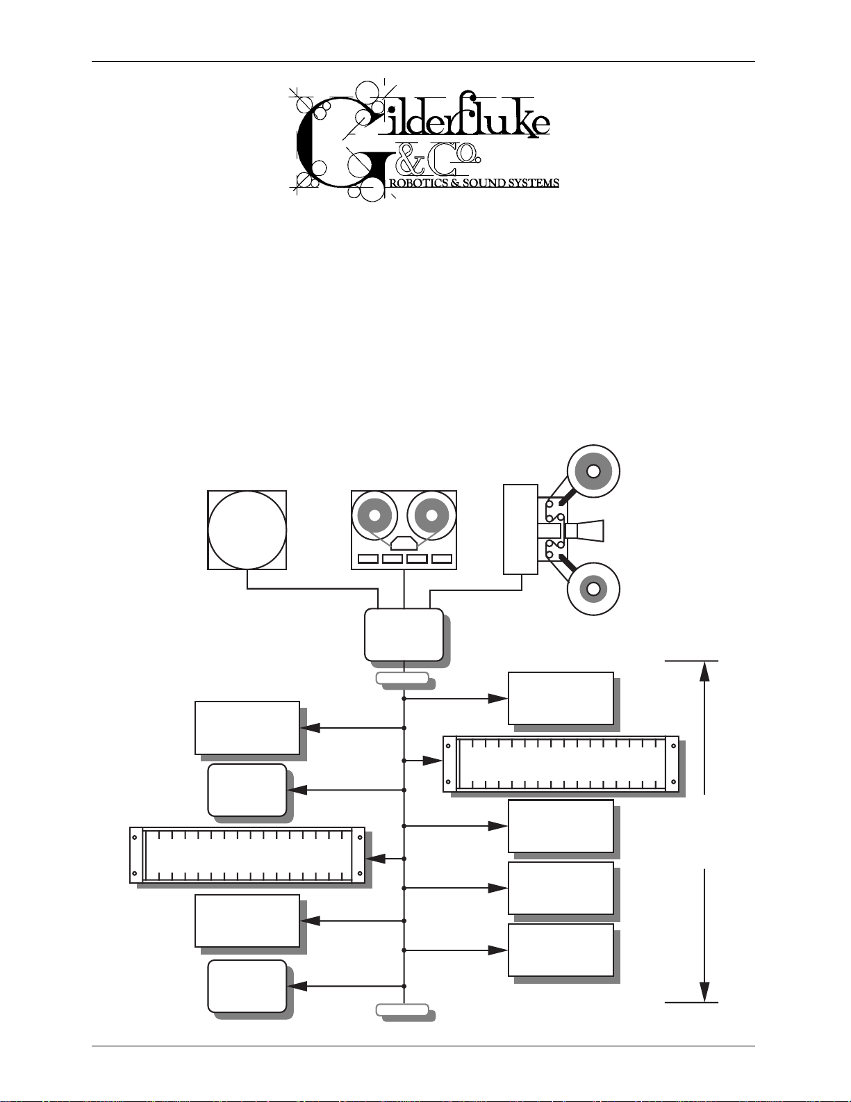
The Smart Brick System is a modular Animation Control System which consists of One
Brick Brain per installation, and any number of Smart Bricks and Heads Up Displays attached to it. Since the number of Smart Bricks attached to each Smart Brick Brain is unlimited, Animation Control Systems of any size to be assembled just by plugging them together.
LaserDisk
Player
SMPTE
source
external clock
source
Smart Brick
Heads Up
Display
Card cage with playback-only
Smart Brick Cards
Smart Brick
Heads Up
Display
Brick
Brain
terminator
playback-only
Smart Brick
Card cage with playback-only
Smart Brick Cards
Smart Brick
up to a mile
playback-only
Smart Brick
playback-only
Smart Brick
terminator
Page 2

GILDERFLUKE & CO.¥ 205 S. FLOWER ST.¥ BURBANK, CA 91502 ¥ 818/840-9484 ¥ 800/776-5972 ¥ FAX 818/840-9485
This page left blank
Page 3

GILDERFLUKE & CO.¥ 205 S. FLOWER ST.¥ BURBANK, CA 91502 ¥ 818/840-9484 ¥ 800/776-5972 ¥ FAX 818/840-9485
The Parts of the Smart Brick System .......................................................... 1
Brick Brain ........................................................................................................................ 1
Smart Bricks ...................................................................................................................... 1
Heads Up Display .............................................................................................................. 2
Quick Start ............................................................................................ 2
Time Bases ........................................................................................... 3
LaserDisk .......................................................................................................................... 3
SMPTE ................................................................................................................................ 4
Internal Time Base ............................................................................................................ 4
External Time Base ............................................................................................................ 5
IBM Backup Box Mode ...................................................................................................... 5
Countdown Between Shows ..................................................................... 7
Smart Brick Brain Dipswitches .................................................................. 8
Brick Brain Connections .......................................................................... 9
Power ............................................................................................................................... 9
SMPTE Input ....................................................................................................................... 9
Tape Deck Control ............................................................................................................ 9
1/4 J-6 input ..................................................................................................................... 9
J-8 input ......................................................................................................................... 10
J-8 output ....................................................................................................................... 10
To Smart Bricks ............................................................................................................... 10
RS-422 Serial Port ........................................................................................................... 10
Smart Brick Configuration ..................................................................... 12
6264LP RAM .................................................................................................................... 12
62256LP RAM .................................................................................................................. 13
27C32 Eprom .................................................................................................................. 13
27C64 Eprom .................................................................................................................. 14
27C128 Eprom ................................................................................................................ 14
27C256 Eprom ................................................................................................................ 15
27C512 Eprom ................................................................................................................ 15
Enabling the Outputs When Stopped ............................................................................... 16
Disabling the Outputs When Stopped ............................................................................. 17
J-6 Digital Output Cables ...................................................................... 19
Output Capacity ............................................................................................................. 21
Programming ...................................................................................... 23
Smart Brick System Commands ............................................................. 27
Global ............................................................................................................................. 28
Track Specific .................................................................................................................29
Cocked ........................................................................................................................... 29
Group (Rack Smart Brick Brain only) ............................................................................... 29
Enter Interactive Echo Mode ...................................................................................... 30
Exit Interactive Echo Mode ......................................................................................... 30
Enter Global Echo Mode ............................................................................................ 30
Exit Global Echo Mode ............................................................................................... 30
Enter Echo All Mode ................................................................................................... 30
Exit Echo All Mode ...................................................................................................... 31
Enter Echo Mode ....................................................................................................... 31
iii of ix
Page 4

GILDERFLUKE & CO.¥ 205 S. FLOWER ST.¥ BURBANK, CA 91502 ¥ 818/840-9484 ¥ 800/776-5972 ¥ FAX 818/840-9485
Exit Echo Mode .......................................................................................................... 31
Track Status Mode ...................................................................................................... 31
Brick Brain Status ........................................................................................................ 32
Switch Status .............................................................................................................. 33
Enter Setup Mode ...................................................................................................... 33
Memory Address Status .............................................................................................. 33
Dipsw1 Status ............................................................................................................. 33
J-6 Port Status ............................................................................................................ 33
Configuration Dump .................................................................................................. 34
Load Configuration .................................................................................................... 34
Start Commands ........................................................................................................ 35
Start Track ................................................................................................................ 35
Start Global ............................................................................................................. 35
Start Cocked ............................................................................................................ 35
Start Group (Rack Smart Brick Brain Only) ......................................................................... 35
Stop Commands ........................................................................................................ 35
Stop Track: ............................................................................................................... 35
Stop Global: ............................................................................................................ 35
Stop Cocked: ........................................................................................................... 35
Stop Group (Rack Smart Brick Brain Only) ......................................................................... 35
Reset Commands ...................................................................................................... 35
Reset Track: ............................................................................................................. 35
Reset Global: ........................................................................................................... 35
Reset Cocked: ......................................................................................................... 35
Reset Group (Rack Smart Brick Brain Only) ....................................................................... 35
Cock Track: ................................................................................................................ 35
Un-Cock Track: ........................................................................................................... 36
Un-Cock Global: ........................................................................................................ 36
Loop Commands: ...................................................................................................... 36
Loop Track: .............................................................................................................. 36
Loop Global: ...........................................................................................................36
Loop Cocked: .......................................................................................................... 36
Loop Group (Rack Smart Brick Brain Only) ........................................................................ 36
Stop at End Commands ............................................................................................. 36
Stop at End Track: ..................................................................................................... 36
Stop at End Global: ................................................................................................... 36
Stop at End Cocked: ................................................................................................. 36
Stop at End Group (Rack Smart Brick Brain Only) ............................................................... 36
Select Show Commands ............................................................................................ 37
Select Show Track: ..................................................................................................... 37
Select Show Global: ................................................................................................... 37
Select Show Cocked: ................................................................................................. 37
Select Show (Rack Smart Brick Brain Only) ........................................................................ 37
Set Delay ................................................................................................................... 37
Set Brick Address ........................................................................................................ 37
Advance One Frame ................................................................................................. 38
Go Back One Frame .................................................................................................. 38
Summary of Commands ....................................................................... 39
Smart Brick Brain Configuration ............................................................. 41
Main Menu ..................................................................................................................... 41
Enter Track Number .................................................................................................... 43
Direct Select .............................................................................................................. 43
Odd Parity Toggle ....................................................................................................... 43
Running Delay ........................................................................................................... 43
Error Count ................................................................................................................ 43
Select from J6 ............................................................................................................ 44
Delay Reload ............................................................................................................. 44
iv of ix
Page 5

GILDERFLUKE & CO.¥ 205 S. FLOWER ST.¥ BURBANK, CA 91502 ¥ 818/840-9484 ¥ 800/776-5972 ¥ FAX 818/840-9485
Tape Deck Pulse ......................................................................................................... 44
Debounce ................................................................................................................. 44
Allow Chains .............................................................................................................. 45
Baud Rate .................................................................................................................. 45
Early Starts ................................................................................................................. 45
More..... ..................................................................................................................... 45
Frame Rate ................................................................................................................ 45
Player Type ................................................................................................................ 46
Input Triggering Commands ....................................................................................... 46
'GREEN' Input Closing Edge ........................................................................................ 46
'GREEN' Input Opening Edge ......................................................................................46
'BLUE' Input Closing Edge ........................................................................................... 46
'BLUE' Input Opening Edge ......................................................................................... 46
'PB' Input Closing Edge .............................................................................................. 46
'PB' Input Opening Edge ............................................................................................46
1/4 J6 Port' Input Closing Edge ..................................................................................... 46
1/4 J6 Port' Input Opening Edge ................................................................................... 46
Countdown End ....................................................................................................... 46
Reset ............................................................................................................. 47
+ Frame ........................................................................................................ 47
Start ............................................................................................................... 47
Loop .............................................................................................................. 47
Stop ............................................................................................................... 47
Stop at End .................................................................................................... 47
Tape Deck ..................................................................................................... 47
eXit Setup Mode ........................................................................................................ 47
Show and String Setup .................................................................................................... 49
Show Number ............................................................................................................ 50
Time Code ................................................................................................................. 50
Brick Start ................................................................................................................... 51
Brick End (non-LaserDisk shows only) ........................................................................... 51
LaserDisk Start (LaserDisk shows only) ........................................................................... 51
Start String ................................................................................................................. 51
End String .................................................................................................................. 51
Next Show .................................................................................................................. 52
Immediate ................................................................................................................. 52
Delay ......................................................................................................................... 52
More... ....................................................................................................................... 52
eXit Setup Mode ........................................................................................................ 52
Setup String Commands ............................................................................................ 53
Setup String 1 ........................................................................................................... 53
Setup String 2 ........................................................................................................... 53
Setup String 3 ........................................................................................................... 53
Setup String 4 ........................................................................................................... 53
Setup String 5 ........................................................................................................... 53
Setup String 6 ........................................................................................................... 53
Setup String 7 ........................................................................................................... 53
Setup String 8 ........................................................................................................... 53
Setup String 9 ........................................................................................................... 53
Rack Smart Brick Brain .......................................................................... 55
Rack Smart Brick Brain Connections .............................................................................. 56
BS-LDMUX ................................................................................................................... 56
Backplane Connections ............................................................................................. 56
1/4 J6 Input ............................................................................................................... 58
J-8 input .................................................................................................................... 58
Rack Smart Brick Brain Messages .................................................................................. 59
Rack Smart Brick Brain Configuration ............................................................................ 61
v of ix
Page 6

GILDERFLUKE & CO.¥ 205 S. FLOWER ST.¥ BURBANK, CA 91502 ¥ 818/840-9484 ¥ 800/776-5972 ¥ FAX 818/840-9485
Enter Track Number .................................................................................................... 62
Baud Rate .................................................................................................................. 62
Odd Parity Toggle ....................................................................................................... 62
VT-52 Mode ............................................................................................................... 62
Numbers .................................................................................................................... 63
Download Configuration Eprom ................................................................................. 63
Respond to Group ..................................................................................................... 63
Set Clock ................................................................................................................... 63
InfraRed Mode ........................................................................................................... 63
Coin-Op Mode ........................................................................................................... 64
Select from J6 ............................................................................................................ 65
Direct Select .............................................................................................................. 65
Debounce ................................................................................................................. 65
Running Delay ........................................................................................................... 65
Tape Deck Pulse ......................................................................................................... 66
Error Count ................................................................................................................ 66
Frame Rate ................................................................................................................ 66
Brick Record Enable ................................................................................................... 66
Early Starts ................................................................................................................. 66
Allow Chains .............................................................................................................. 67
Countdown Hold ........................................................................................................ 67
Player Type ................................................................................................................ 67
LaserDisk Time ............................................................................................................ 67
Dropout Protection ..................................................................................................... 67
Input Triggering Commands ....................................................................................... 68
Pause/Return to Zero (RTZ) ............................................................................................. 68
Continue/Increment ................................................................................................... 68
Start ....................................................................................................................... 69
Loop ...................................................................................................................... 69
Stop ....................................................................................................................... 69
Stop at End .............................................................................................................. 69
Tape Deck ............................................................................................................... 69
More..... ..................................................................................................................... 70
Load Defaults ............................................................................................................. 70
eXit Setup Mode ........................................................................................................ 70
Rack Smart Brick Brain Show Menu ................................................................................ 71
Time Code ................................................................................................................. 71
Brick Start ................................................................................................................... 72
Brick End .................................................................................................................... 72
Next Show .................................................................................................................. 72
Immediate ................................................................................................................. 72
Delay ......................................................................................................................... 73
Start String ................................................................................................................. 73
Multi-Disk String .......................................................................................................... 73
End String .................................................................................................................. 74
LaserDisk Starts ........................................................................................................... 74
LaserDisk 1 .............................................................................................................. 74
LaserDisk 2 .............................................................................................................. 74
LaserDisk 3 .............................................................................................................. 74
LaserDisk 4 .............................................................................................................. 74
LaserDisk 5 .............................................................................................................. 74
LaserDisk 6 .............................................................................................................. 74
LaserDisk 7 .............................................................................................................. 74
Next Entry .................................................................................................................. 75
Last Entry ................................................................................................................... 75
Kopy Another Show .................................................................................................... 75
More..... ..................................................................................................................... 75
Load Defaults ............................................................................................................. 75
vi of ix
Page 7

GILDERFLUKE & CO.¥ 205 S. FLOWER ST.¥ BURBANK, CA 91502 ¥ 818/840-9484 ¥ 800/776-5972 ¥ FAX 818/840-9485
eXit Setup Mode ........................................................................................................ 75
Rack Smart Brick Brain String Setup Menu ...................................................................... 77
Alter Strings ................................................................................................................ 77
More..... ..................................................................................................................... 77
Load Defaults ............................................................................................................. 78
eXit Setup Mode ........................................................................................................ 78
Rack Smart Brick Brain Delay Setup Menu ...................................................................... 79
Set Delays .................................................................................................................. 79
More..... ..................................................................................................................... 79
Load Defaults ............................................................................................................. 79
eXit Setup Mode ........................................................................................................ 79
Rack Smart Brick Brain 1/4 J6 Setup Menu ..................................................................... 81
Input Triggering Commands ....................................................................................... 81
Pause/Return to Zero (RTZ) ............................................................................................. 82
Continue/Increment ................................................................................................... 82
Start ....................................................................................................................... 82
Loop ...................................................................................................................... 82
Stop ....................................................................................................................... 82
Stop at End .............................................................................................................. 83
Tape Deck ............................................................................................................... 83
Input Triggering Commands ....................................................................................... 83
Select from J6 ............................................................................................................ 83
Direct Select .............................................................................................................. 84
More..... ..................................................................................................................... 84
Load Defaults ............................................................................................................. 84
eXit Setup Mode ........................................................................................................ 84
Rack Smart Brick Brain Schedule Setup Menu ................................................................ 87
Alter Entry .................................................................................................................. 87
Next Entry .................................................................................................................. 87
Last Entry ................................................................................................................... 87
Kopy Entry .................................................................................................................. 87
More..... ..................................................................................................................... 87
Load Defaults ............................................................................................................. 88
eXit Setup Mode ........................................................................................................ 88
Rack Smart Brick Brain Calendar Setup Menu ................................................................ 89
Alter Entry .................................................................................................................. 89
Next Entry .................................................................................................................. 89
Last Entry ................................................................................................................... 89
Kopy Entry .................................................................................................................. 89
More..... ..................................................................................................................... 90
Load Defaults ............................................................................................................. 90
eXit Setup Mode ........................................................................................................ 90
Smart Brick MiniBrain ............................................................................ 91
Brick Memory Size ....................................................................................................... 92
Double Show ............................................................................................................. 92
Frame Rate ................................................................................................................ 93
Stop On Green Opening ............................................................................................ 93
Run Continuous ......................................................................................................... 93
Micro Console ..................................................................................... 95
Micro Console Configuration ......................................................................................... 97
Micro Console mode ................................................................................................. 99
Numbering System ..................................................................................................... 99
VT-52 mode ............................................................................................................... 99
DMX Checksums ........................................................................................................ 99
Assignment Range ................................................................................................... 100
vii of ix
Page 8

GILDERFLUKE & CO.¥ 205 S. FLOWER ST.¥ BURBANK, CA 91502 ¥ 818/840-9484 ¥ 800/776-5972 ¥ FAX 818/840-9485
Dumb Bricks ............................................................................................................. 100
Step Forward ............................................................................................................ 100
Step Backward ......................................................................................................... 100
Go To Frame ............................................................................................................ 100
Set Start Frame ........................................................................................................ 100
Set End Frame ......................................................................................................... 100
Save Eprom ............................................................................................................. 101
Verify Eprom ............................................................................................................ 101
Restore Eprom ......................................................................................................... 101
Save Archive ............................................................................................................ 102
Verify Archive ........................................................................................................... 102
Restore Archive ........................................................................................................ 103
Clear Brick ............................................................................................................... 103
Restore Default Config. ............................................................................................ 103
Save Current Config. ............................................................................................... 103
Test Brick .................................................................................................................. 103
Test Playback-Only Brick ............................................................................................ 104
Micro Console Buttons ................................................................................................. 105
Hex/Decimal/Percent ................................................................................................ 105
Alternate/Reverse ..................................................................................................... 105
Analog/External/Digitals ............................................................................................ 105
Assign ...................................................................................................................... 106
Unassign .................................................................................................................. 107
Togglodyte Animation Test Tool ............................................................ 109
Assign ...................................................................................................................... 110
Alt./Rev. ................................................................................................................... 11 0
Analog/Digital .......................................................................................................... 111
Setup ....................................................................................................................... 111
Special Encoder Prescaler ......................................................................................... 112
Digital Name ......................................................................................................... 112
Digital Number .......................................................................................................112
Analog Number ...................................................................................................... 112
Timer A .................................................................................................................. 112
Timer B .................................................................................................................. 112
Timer C ................................................................................................................. 112
Timer D .................................................................................................................. 112
Backlighting Stay On ................................................................................................ 113
Battery Stay On ........................................................................................................ 113
Default to Digital/Analog Input .................................................................................... 113
Default Digital Channel ............................................................................................113
Digital Default Momentary/Alternate Action .................................................................... 113
Default Analog Channel ........................................................................................... 113
Analog Default Normal/Reversed Direction .................................................................... 113
Default Analog Resolution ......................................................................................... 113
DMX-512 Checksum ................................................................................................ 113
Write to EEprom/Read from EEprom .............................................................................. 113
Light ........................................................................................................................ 113
Sequencer Record .................................................................................................. 113
Start/Stop Sequencer ............................................................................................... 114
Heads Up Display .............................................................................. 115
Error Messages ............................................................................................................. 116
Start and End Strings .......................................................................... 119
ASCII Characters to be Sent Out ................................................................................... 121
ASCII Characters to be Received ................................................................................. 122
viii of ix
Page 9

GILDERFLUKE & CO.¥ 205 S. FLOWER ST.¥ BURBANK, CA 91502 ¥ 818/840-9484 ¥ 800/776-5972 ¥ FAX 818/840-9485
PIONEER LaserDisk Commands ............................................................. 123
SONY LaserDisk Commands ................................................................. 127
Panasonic LaserDisk Commands ......................................................... 131
HEXadecimal to Decimal to Percentage ................................................ 134
ix of ix
Page 10

GILDERFLUKE & CO.¥ 205 S. FLOWER ST.¥ BURBANK, CA 91502 ¥ 818/840-9484 ¥ 800/776-5972 ¥ FAX 818/840-9485
This page was left blank too
x of x
Page 11

GILDERFLUKE & CO.¥ 205 S. FLOWER ST.¥ BURBANK, CA 91502 ¥ 818/840-9484 ¥ 800/776-5972 ¥ FAX 818/840-9485
- The Parts of the Smart Brick System -
The Brick Brain is a small microprocessor controlled unit which can synchronize any
number of Smart Bricks to a LaserDisk player, SMPTE time code, internal time base, or external time base. In addition it can control the LaserDisk player or tape deck and provide a
countdown timer for the delay between shows. For all but the SMPTE time code, it can instantly randomly access any show stored in the system (SMPTE synchronized shows are
slaved to whatever show the SMPTE time code is requesting). At the end of any show it can
automatically jump to any other show, either with or without a user adjustable delay before playing this next show. If it is already playing a show and it gets a request for another
show, it can be told to ignore the request, store it until done with the current show, or jump
to it immediately.
Brick Brains are attached to the Smart Bricks and Heads Up Displays by up to a mile of
6 conductor modular telephone wire. (This is the same type of wire and connector as
found on the standard Bricks, but is incompatible with the signals which they use.) Just
about any number of Smart Bricks can be attached to a single Brain (If the wire runs are
long and there are a lot of Smart Bricks attached, a repeater may be required in the line.)
Make sure that this cable does not have its wires flipped from one end to the other. If the
wire run is long, then a terminator should be installed at the two extreme ends of the line.
The Smart Bricks are available as record/playback Smart Bricks, playback-only Smart
Bricks, or card cage mounted playback-only Smart Brick cards. Each Smart Brick can
control up to four 8 bit channels. These can be used as 32 on/off ÔdigitalÕ controls, as four
8 bit wide analog channels, or as any combination of the two. If one Smart Brick doesnÕt
have enough outputs, you simply add more, stacking them until you have enough outputs to do the job. Analog resolutions greater than eight bits can easily be achieved by
combining the outputs from more than a single channel.
The Smart Bricks can all be located at one or more central locations, or they can be
built right into whatever it is they are controlling. This latter method allows you to wire an entire attraction by just stringing up a 6 conductor modular telephone line to connect all
your figures. It also allows you to remove a figureÕs animation system along with the figure
when it is removed for maintenance, and then run them both on a service bench away
from the rest of the show for testing and adjustment. A Smart Brick System can consist of
any combination of record/playback Smart Bricks, playback-only Smart Bricks and card
cage mounted Smart Bricks.
Record/Playback Smart Bricks store the data as it is recorded into static RAM memory
chips. These are protected from power outages and data loss by a nickel-cadmium battery. This battery is always on a trickle charge when the Smart Brick is plugged in, and
should hold the data safe for years. A keyswitch on the front of each record/playback
Smart Brick, as well as a small switch inside the Brick Brain, keep down the possibility of accidental or unauthorized tampering with recorded show data.
Playback-only Smart Bricks store their data in Eprom type memory chips. This is about
the safest way known to store any type of data. One Eprom is used to store each individual eight bit wide channel, which means that when you have to perform a minor change
in one output, you donÕt have to replace all the Eproms in the system.
1 of 134
Page 12

GILDERFLUKE & CO.¥ 205 S. FLOWER ST.¥ BURBANK, CA 91502 ¥ 818/840-9484 ¥ 800/776-5972 ¥ FAX 818/840-9485
Since the Smart Bricks donÕt have any frame counters on them, two styles of Heads Up
Display are available for use in the Smart Brick System. One is a stand-alone unit, while
the other is made to mount in a standard 19Ò rack. They will provide you with a large format display of the show time (SMPTE time code if using it), and frame number in the Smart
Bricks being accessed. Additionally, they will display the countdown until the start of the
next show if this feature is used. Like the Smart Bricks, any number of these Heads Up
Displays can be placed anywhere in the system by simply plugging them into the same
6 conductor telephone line which connects the Smart Bricks with the Brick Brain. They can
be installed as a permanent part of the system or temporarily for use while programming
the show. The stand-alone Heads-Up-Display is not multiplexed, which allows it to appear
on film or video without any flickering
¥¥¥¥¥¥¥¥¥¥¥¥¥¥¥¥¥¥¥¥¥¥¥¥¥¥¥¥¥¥¥¥¥¥¥¥¥¥¥¥¥¥¥¥¥¥¥¥¥¥¥¥¥¥¥¥¥¥¥¥¥¥¥¥¥¥¥¥¥¥¥¥¥¥¥¥¥¥¥¥¥¥¥¥¥¥¥¥¥¥¥¥
Quick Start:
When shipped, the Brick Brain is usually configured to start
playing show number one when the 'manual start' pushbutton on its front is pressed. This show is set up to clock
from the internal time base at 30 frames per second. To
see the system work, attach some Smart Bricks and Heads
Up Displays to the connector marked 'to smart bricks' on
the Brick Brain and plug everything in. When you push the
'manual start' pushbutton, you should see the system start
clocking through the frames. If you then attach a Micro
Console to a record/playback Smart Brick, you should be
able to turn on the key on Smart Brick's front and actually
start recording show data. Each time you push the 'manual start' button, show number one should start over from its
beginning.
¥¥¥¥¥¥¥¥¥¥¥¥¥¥¥¥¥¥¥¥¥¥¥¥¥¥¥¥¥¥¥¥¥¥¥¥¥¥¥¥¥¥¥¥¥¥¥¥¥¥¥¥¥¥¥¥¥¥¥¥¥¥¥¥¥¥¥¥¥¥¥¥¥¥¥¥¥¥¥¥¥¥¥¥¥¥¥¥¥¥¥
2 of 134
Page 13

GILDERFLUKE & CO.¥ 205 S. FLOWER ST.¥ BURBANK, CA 91502 ¥ 818/840-9484 ¥ 800/776-5972 ¥ FAX 818/840-9485
- Time Bases -
The Smart Brick System can be used with four normal time bases, as well as one special mode for use with an IBM Backup Box. As long as the frame rate being used is the
same for all shows, you can use all of the time bases within the same system. The supported time bases are:
1) LaserDisk: The Smart Brick Brain has an RS-422 serial port on it which can be attached directly to
the serial port on many professional quality LaserDisk players. The Brick Brain talks to the LaserDisk player
to synchronize the entire system to the show being played. All control for the LaserDisk player is provided
by the Brick Brain. Systems with LaserDisk players in them are limited to running either 15 or 30 Frames
Per Second (FPS), as the latter is the frame rate at which the video signal from the player is reproduced.
A Constant Angular Velocity (CAV) format LaserDisk has the capacity of 1/2 hour per surface, and so this
usually serves as the show capacity limitation for the system. Show capacities of the Smart Bricks are as
follows:
15 frames/second (show capacity of 1092 sec. for 16K Smart Brick, 4369 sec. for 64K Smart Brick)
30 frames/second (show capacity of 546 sec. for 16K Smart Brick, 2184 sec. for 64K Smart Brick)
As of this writing the Smart Brick Brain has not been tested for compatibility with PAL and SECAM video
format LaserDisk players running at 25 Frames per second, so the operation with these can not be guaranteed. Capacity at this frame rate is:
25 frames/second (show capacity of 655 sec. for 16K Smart Brick, 2621 sec. for 64K Smart Brick)
The LaserDisk players which are currently supported are the Pioneer ÔLD-Õ and Sony ÔLDP-Õ series. The
Pioneer LaserDisk code was developed and tested on an LD-V8000, which is PioneerÕs top of the line
unit. It should be compatible with all of the earlier models in this series as well. Current Pioneer LaserDisk
models are:
LD-V8000 (recommended)
LD-V6000A
LD-V6000
LD-V3000
LD-V7820-3
The advantages of the LD-V8000 are: four audio channels (two analog and two digital), frame
memory during random access, separate front panel controls, and faster access times than all of itÕs
predecessors.
The Sony LaserDisk code was developed and tested on an LDP-2000. It should be compatible with all
of the other models in this series as well. Current Sony LaserDisk models are
LDP-180 (requires an IF-180 serial port option)
LDP-1000A
LDP-1500
LDP-2000
If more than a single LaserDisk is to be controlled from a single Smart Brick System, then a LaserDisk
Multiplexer must be used. Each of these allow four LaserDisk players to be connected to the Smart Brick
Brain. Each additional player requires an additional ÔshowÕ to hold the disk frame numbers used by that
player. This lowers the total number of shows the system can support by half each time you add an additional LaserDisk player to be controlled.
LaserDisks are available in two different recording formats. These are Constant Angular Velocity
(CAV) and Constant Linear Velocity (CAV). The only format which will work with the Smart Brick System is
the CAV format. This is because the CAV format is the only one which can be used with all of the commands a LaserDisk player support. Capacity of CAV LaserDisk is up to 54,000 frames or 1/2 hour per side.
3 of 134
Page 14

GILDERFLUKE & CO.¥ 205 S. FLOWER ST.¥ BURBANK, CA 91502 ¥ 818/840-9484 ¥ 800/776-5972 ¥ FAX 818/840-9485
2) SMPTE: (pronounced ÒSIMP-TÒ) is a time code which was developed by the Society of Motion
Picture and Television Electronics for use in audio, film, and television production. It is normally recorded
on a spare audio track on the medium being used (audio tape, video tape, or film), and then used to
synchronize various pieces of compatible equipment together. As an industry standard, virtually every
audio, video or film studio will have the equipment to lay down a SMPTE time code track.
SMPTE is usually recorded at 30 frames per second (although 25 frames per second is used in
Europe and places where this is the normal television frequency, and 24 frames per second is occasionally used in film production). What this means is that 30 (or 24 or 25) times each second a number is
recorded on the tape or film which represents the hours, seconds, minutes and frame (00:00:00.00)
represented by this particular little stretch of medium. Since each little stretch is represented by a unique
number, SMPTE is known as an ÔabsoluteÕ time code. No matter where the tape is, the Brick Brain will instantly evaluate the numbers it gets from the SMPTE time code, and play the appropriate animation
data.
With SMPTE synchronized shows, the SMPTE ÔhourÕ is used to tell the Brick Brain which show it is actually
running. The ÔhoursÕ SMPTE supports are 00 through 23 to give you 24 possible SMPTE synchronized shows
(SMPTE hour Ô00Õ is mapped to show number Ô24Õ by the Smart Brick Brain, since 00 isnÕt a valid show
number). Any individual show can be as long as an hour. When told to start running a SMPTE show, the
Brick Brain will start listening for any SMPTE coming in. When it picks up a good SMPTE signal, it looks at the
ÔhourÕ, and then checks to see if it is the number of a SMPTE synchronized show, and if so, plays it. Note
that if the show number the Brick Brain expects to be played when it starts listening for the SMPTE is not
the show number it actually receives, it will play the latter. If the show number it receives isnÕt assigned
as a SMPTE show, then it will display an error message on the Heads Up Display and not play anything.
For this reason random access commands for SMPTE synchronized shows are somewhat at the mercy of
whatever SMPTE hour is actually received from the SMPTE source.
If more than 24 SMPTE synchronized shows are required, you can use an output from the animation
system to stop the system Ômid showÕ. This technique can be used to break up a single long show into as
many shorter sequences as you would like.
Since SMPTE is often provided by an audio or video tape deck, the Brick Brain has three outputs
which can be programmed to send signals to the tape deck at the beginnings and ends of the shows.
These are typically used to start, stop and rewind the tape deck. These outputs are simple relay closures,
which can usually be attached directly to the remote control inputs on a tape deck.
Frame rates supported by the Brick Brain are 15 or 30 FPS when using SMPTE recorded at 30 FPS, 25
FPS when using SMPTE recorded at 25 FPS, and 12 or 24 FPS when using SMPTE recorded at 24 FPS. All
type of SMPTE must be recorded Ônon-drop frameÕ for compatibility with the Brick Brain. Show capacities
for Smart Bricks are as follows:
12 frames/second (show capacity of 1365 sec. for 16K Smart Brick, 5461 sec. for 64K Smart Brick)
15 frames/second (show capacity of 1092 sec. for 16K Smart Brick, 4369 sec. for 64K Smart Brick)
24 frames/second (show capacity of 682 sec. for 16K Smart Brick, 2730 sec. for 64K Smart Brick)
25 frames/second (show capacity of 655 sec. for 16K Smart Brick, 2621 sec. for 64K Smart Brick)
30 frames/second (show capacity of 546 sec. for 16K Smart Brick, 2184 sec. for 64K Smart Brick)
SMPTE is a type of time code which is prone to minor errors. The Brick Brain automatically bridges over
these until it gets a number of consecutive consistent SMPTE frames. You can set the size of this number
when configuring the Brick Brain to anywhere from 1 to 256 consecutive frames.
3) Internal Time Base: If there is no need for synchronization to an audio or video source, you can
use the crystal controlled time base in the Brick Brain to clock the entire system. This type of show is often
used for chase sequences, test shows, when you just donÕt need to synchronize a show to anything else,
or to keep the figures moving between the main SMPTE or LaserDisk synchronized shows. Frame rates
supported are:
1 FPS (show capacity of 16,384 sec. for 16K Smart Brick, 65,536 sec. for 64K Smart Brick)
2 FPS (show capacity of 8192 sec. for 16K Smart Brick, 32,768 sec. for 64K Smart Brick)
4 FPS (show capacity of 4096 sec. for 16K Smart Brick, 16,384 sec. for 64K Smart Brick)
5 FPS (show capacity of 3276 sec. for 16K Smart Brick, 13,107 sec. for 64K Smart Brick)
8 FPS (show capacity of 2048 sec. for 16K Smart Brick, 8192 sec. for 64K Smart Brick)
4 of 134
Page 15

GILDERFLUKE & CO.¥ 205 S. FLOWER ST.¥ BURBANK, CA 91502 ¥ 818/840-9484 ¥ 800/776-5972 ¥ FAX 818/840-9485
10 FPS (show capacity of 1638 sec. for 16K Smart Brick, 6553 sec. for 64K Smart Brick)
12 FPS (show capacity of 1365 sec. for 16K Smart Brick, 5461 sec. for 64K Smart Brick)
15 FPS (show capacity of 1092 sec. for 16K Smart Brick, 4369 sec. for 64K Smart Brick)
16 FPS (show capacity of 1024 sec. for 16K Smart Brick, 4096 sec. for 64K Smart Brick)
20 FPS (show capacity of 819 sec. for 16K Smart Brick, 3276 sec. for 64K Smart Brick)
24 FPS (show capacity of 682 sec. for 16K Smart Brick, 2730 sec. for 64K Smart Brick)
25 FPS (show capacity of 655 sec. for 16K Smart Brick, 2621 sec. for 64K Smart Brick)
30 FPS (show capacity of 546 sec. for 16K Smart Brick, 2184 sec. for 64K Smart Brick)
32 FPS (show capacity of 512 sec. for 16K Smart Brick, 2048 sec. for 64K Smart Brick)
50 FPS (show capacity of 327 sec. for 16K Smart Brick, 1310 sec. for 64K Smart Brick)
60 FPS (show capacity of 273 sec. for 16K Smart Brick, 1092 sec. for 64K Smart Brick)
64 FPS (show capacity of 256 sec. for 16K Smart Brick, 1024 sec. for 64K Smart Brick)
75 FPS (show capacity of 218 sec. for 16K Smart Brick, 873 sec. for 64K Smart Brick)
100 FPS (show capacity of 163 sec. for 16K Smart Brick, 655 sec. for 64K Smart Brick)
4) External Time Base: This is generally used when you need to tie the Smart Brick System to an ex-
ternal clock. Typical uses of external time base sync are to lock the system to a mechanical device like a
motion picture camera or projector so that it will follow at any speed, or to synchronize two incompatible
systems so that data can be transferred between the two. Frame rates supported are from 1 to 100 FPS
(this is simply the number of frames displayed on the Heads Up Display, as the actual rate will follow
whatever clock rate is fed to the Brick Brain).
5) IBM Backup Box Mode: This is a special mode which is used only when using the IBM Backup Box
with the Smart Brick System. It makes the Smart Brick System look to the IBM Backup Box more like a standard externally clocked Micro MACs system. It is entered by turning on SWITCH 8 in the dipswitch inside
the Brick Brain. When in this mode, the hours, minutes, seconds, and frame numbers on the Heads Up
Display will not be updated and the Smart Bricks will be treated as a single block of 16K or 64K bytes of
memory. If you have broken up the memory into any separate ÔshowsÕ, these will simply be ignored.
These shortcuts are to save time so that the system can run at the higher speeds the IBM Backup Box
wants to see. Even so, you may find that the Smart Brick System still isnÕt as fast as the IBM Backup Box
wants to see it (a lot of this depends on how fast your IBM compatible runs). For this reason you may
need to slow down the IBM Backup Box software by setting the ÔFast Forward SpeedÕ. Larger numbers slow
the Backup Box down, while smaller numbers run faster. To test the speed to determine the proper settings for the Ôfast forward speedÕ, do the following:
1) Connect the IBM backup Box to the Smart Brick System normally by:
a) connect the Smart Brick to the Micro Console and Brick Brain as you would normally.
b) run a 6 conductor telephone style cable between the ÔJ8 inputÕ on the Brain and the ÔJ8
outÕ in the IBM Backup box.
c) connect the 1/4 J-6 for the channel you will be using to the IBM backup Box.
d) connect the parallel port from the IBM compatible you will be using to the IBM Backup
Box.
2) Turn on dipswitch number 8 in the Smart Brick Brain.
3) Using the Ôsingle stepÕ command (ÒsÒ) in the IBM Backup Box software, program in a simple and
easily recognizable sequence in the first few frames of the Smart Brick
4) Write this data to the disk of the IBM compatible using the instructions in the IBM Backup Box
manual.
5) Read this data back into the Smart Brick using the instructions in the IBM Backup Box manual.
6) Now single step through the first few frames of the reloaded data and see if they are the
same as when you programmed them, and especially that the data is in the same frame
numbers as they were when you programmed them.
7a) If the data has changed or has moved, then you need to use a larger number for the Ôfast for-
ward speedÕ. Enter the Ôfast forward speedÕ and repeat this sequence starting at step 3 above
again to make sure that the IBM Backup Box is now running slowly enough.
5 of 134
Page 16

GILDERFLUKE & CO.¥ 205 S. FLOWER ST.¥ BURBANK, CA 91502 ¥ 818/840-9484 ¥ 800/776-5972 ¥ FAX 818/840-9485
7b) If the data has not changed, then the two systems are staying in sync. You can use the cur-
rent setting for the Ôfast forward speedÕ, or you can try speeding it up a bit by lowering the
number in the Ôfast forward speedÕ, and repeat this sequence starting at step 3 to see if it is
now too fast. You should leave a little bit of a safety margin over which the system wonÕt run in
sync to allow for longer wire runs and other factors which might slow the system down further.
8) Turn dipswitch 8 off if you are done with the IBM Backup Box to return the Smart Brick System to
itÕs normal operating modes.
6 of 134
Page 17

GILDERFLUKE & CO.¥ 205 S. FLOWER ST.¥ BURBANK, CA 91502 ¥ 818/840-9484 ¥ 800/776-5972 ¥ FAX 818/840-9485
- Countdown Between Shows -
At the end of any show you can tell the Brick Brain to either stop, chain immediately to the next
show, or start a countdown. At the end of this countdown, you can tell the system to start the next show,
or just close one of the relay outputs which are normally used to control the tape deck if you need to
trigger some other piece of equipment
The length of the countdown can be set at any time by setting a thumbwheel switch located on the
front of the Smart Brick Brain. The positions set the delays as follows:
1) 1 x 'delay reload' (for 15 seconds delay when delay reload is set to 15 seconds)
2) 2 x 'delay reload' (for 30 seconds delay when delay reload is set to 15 seconds)
3) 4 x 'delay reload' (for 1 minute delay when delay reload is set to 15 seconds)
4) 8 x 'delay reload' (for 2 minutes delay when delay reload is set to 15 seconds)
5) 20 x 'delay reload' (for 5 minutes delay when delay reload is set to 15 seconds)
6) 40 x 'delay reload' (for 10 minutes delay when delay reload is set to 15 seconds)
7) 80 x 'delay reload' (for 20 minutes delay when delay reload is set to 15 seconds)
8) 120 x 'delay reload' (for 30 minutes delay when delay reload is set to 15 seconds)
9) 240 x 'delay reload' (for 1 hour delay when delay reload is set to 15 seconds)
0) stops cycling shows
The 'DELAY RELOAD' value is set in the configuration menu. A typical value is 15 seconds. This give
you the delays shown above. If the value for the 'DELAY RELOAD' were doubled, then the delays would
also double. If it were set to a value of 90 seconds, the maximum delay would be 6 hours. If during the
course of a countdown the Brick Brain gets any ÔRESETÕ command (either through the serial port or any of
the hardware inputs) it will re-start the countdown from the initial value as set by the thumbwheel switch
and 'DELAY RELOAD' value.
At the end of the countdown, the Brick Brain again checks the value on the thumbwheel switch. If it
is now set to Ô0Õ, then the Brick Brain takes no further action. If it is set to anything else, then it treats the
end of the countdown just like an input coming from one of the Brick BrainÕs switch inputs. You can tell
the Brick Brain to do any of the following:
1) Reset
2) + Frame
3) Start
4) Start Looping (normal setting)
5) Stop
6) Stop at end
7) a) close ÔstopÕ relay output
b) close ÔrewindÕ relay output
c) close ÔplayÕ relay output
Setting the ÔResetÕ, Ô+ FrameÕ, ÔStopÕ, or ÔStop at EndÕ settings are fairly pointless in that there will be
no shows running when the countdown ends, and so should never be needed. Setting the ÔSTARTÕ command will start whatever the next show should be as set by the Ônext showÕ entry in the configuration for
the last show which was played (see the show configuration section of this manual). At the end of that
show, however, nothing more will happen.
The normal setting for the end of the countdown is to ÔSTART LOOPINGÕ. This tells the Brick Brain to
start the ÔnextÕ show playing just as with the ÔSTARTÕ command, but at the end of this show, it will check
the configuration for the show to see if the ÔIMMEDIATEÕ or ÔDELAYÕ flags are set. If they are, then the next
show or a new delay will be started as appropriate. The Smart Brick System can then continue cycling
shows until it is told to stop. Any one of the tape deck output commands can be used by themselves or
in conjunction with any of the other commands.
7 of 134
Page 18

GILDERFLUKE & CO.¥ 205 S. FLOWER ST.¥ BURBANK, CA 91502 ¥ 818/840-9484 ¥ 800/776-5972 ¥ FAX 818/840-9485
- Smart Brick Brain Dipswitches -
There is one eight position dipswitch located inside the cover of the Smart Brick Brain. Once set, it is
not normally used again. Most of these settings are available through the menus on the Rack Smart Brick
Brain.
SWITCH 1: not used
SWITCH 2: Bridge LaserDisk errors. When on, the Brick Brain will try to bridge over any dropouts in
the communications with a LaserDisk player. This is used to bridge over the three or more seconds it takes a LaserDisk player to recover from a glitch.
SWITCH 3: Countdown Halt mode: When on, any input on the BLUE line will freeze the countdown
between shows at the current value. When this input is released, the countdown will continue
just as if nothing had happened.
SWITCH 4: Coin-Op mode. Turning this switch on puts the brick into a special mode used for coin
operated games. A show will be started each time a start command comes in on the green
input (A number of shows are normally set up so that a different show plays at each start). The
countdown selects and plays show 3Fh each time it ends. If the RED input gets a closure,
then show 3Eh will play.
SWITCH 5: This dipswitch is used to tell the Brick Brain how big the memory installed in the Smart
Bricks is. This switch should be turned ÔonÕ when using 64K Smart Bricks, and ÔoffÕ when using
16K Smart Bricks. When running at 15 frames per second, a 64K Smart Brick has a capacity of
just over 72 minutes while a 16K one is around 18 minutes. At 30 frames per second the capacities are 36 minutes for a 64K Brick and 9 minutes for a 16K Brick.
SWITCH 6: This switch can be used to disable all of the ÔRecord KeyswitchesÕ on all of the Smart
Bricks in your installation. When this switch is ÔonÕ, it is possible to record data into the Smart
Bricks. When it is ÔoffÕ, there is no way to put the Smart Bricks into ÔrecordÕ mode, even if the
ÔRecord KeyswitchÕ on the Bricks is turned ÔonÕ. The record LEDs on the front of the Smart Bricks
will not even turn on if recording has been disabled in this way. After programming a show
you should turn this switch ÔoffÕ to absolutely eliminate the possibility of someone turning on a
Smart BrickÕs ÔrecordÕ keyswitch and altering any data.
SWITCH 7: This switch is used to load the default values into the EEprom on the Brick Brain. You
should never need to use this switch. What it does is sets the serial port to 9600 baud and the
card address to number 00. This brings a new Brick Brain up far enough for us to load the remaining parts of the configuration and test it.
SWITCH 8: This switch should be turned ÔonÕ when using an IBM Backup box with the Brick Brain. At
all other times it should be left ÔoffÕ. If it is on, the Brick Brain will ignore any inputs on the PB or
1/4 J-6 inputs, and will only reset and step frames in response to inputs from the J-8 input.
8 of 134
Page 19
+
GILDERFLUKE & CO.¥ 205 S. FLOWER ST.¥ BURBANK, CA 91502 ¥ 818/840-9484 ¥ 800/776-5972 ¥ FAX 818/840-9485
- Brick Brain Connections -
There are 8 connections which can be made to the Smart Brick Brain. These are:
1) Power: This is a small 12 VDC wall mounted transformer which just needs to be plugged in to
117 VAC.
¥¥¥¥¥¥¥¥¥¥¥¥¥¥¥¥¥¥¥¥¥¥¥¥¥¥¥¥¥¥¥¥¥¥¥¥¥¥¥¥¥¥¥¥¥¥¥¥¥¥¥¥¥¥¥¥¥¥¥¥¥¥¥¥¥¥¥¥¥¥¥¥¥¥¥¥¥¥¥¥¥¥¥¥¥¥¥¥¥¥¥¥¥¥¥¥¥¥¥¥¥¥¥¥¥¥¥¥¥¥¥¥¥¥¥¥¥¥¥
2) SMPTE Input: This is a female RCA jack which should be attached to the source of SMPTE time
code being used (if any). This input has a 10 Kohm input impedance, and expects to see a
SMPTE signal level of about 0 VU.
¥¥¥¥¥¥¥¥¥¥¥¥¥¥¥¥¥¥¥¥¥¥¥¥¥¥¥¥¥¥¥¥¥¥¥¥¥¥¥¥¥¥¥¥¥¥¥¥¥¥¥¥¥¥¥¥¥¥¥¥¥¥¥¥¥¥¥¥¥¥¥¥¥¥¥¥¥¥¥¥¥¥¥¥¥¥¥¥¥¥¥¥¥¥¥¥¥¥¥¥¥¥¥¥¥¥¥¥¥¥¥¥¥¥¥¥¥¥¥
3) Tape Deck Control: This input is normally used to control any tape decks attached to the Brick
Brain. The connections are as follows:
1) Ground
2) +5 VDC
3) Foil A: This is a non-optoisolated 5 volt logic level version of the BLUE input on the J-8
input. There is a 4.7 Kohm pullup resistor to 5 VDC on this input.
4) Foil B: This is a non-optoisolated 5 volt logic level version of the GREEN input on the J-8
input. There is a 4.7 Kohm pullup resistor to 5 VDC on this input.
5 & 6) Rewind Output: These are the relay outputs which close when a ÔRewindÕ command
is encountered in a string being sent at the start or end of any show.
7 & 8) Play Output: These are the relay outputs which close when a ÔPlayÕ command is en-
countered in a string being sent at the start or end of any show.
9 & 10) Stop Output: These are the relay outputs which close when a ÔSTOPÕ command is
encountered in a string being sent at the start or end of any show.
¥¥¥¥¥¥¥¥¥¥¥¥¥¥¥¥¥¥¥¥¥¥¥¥¥¥¥¥¥¥¥¥¥¥¥¥¥¥¥¥¥¥¥¥¥¥¥¥¥¥¥¥¥¥¥¥¥¥¥¥¥¥¥¥¥¥¥¥¥¥¥¥¥¥¥¥¥¥¥¥¥¥¥¥¥¥¥¥¥¥¥¥¥¥¥¥¥¥¥¥¥¥¥¥¥¥¥¥¥¥¥¥¥¥¥¥¥¥¥
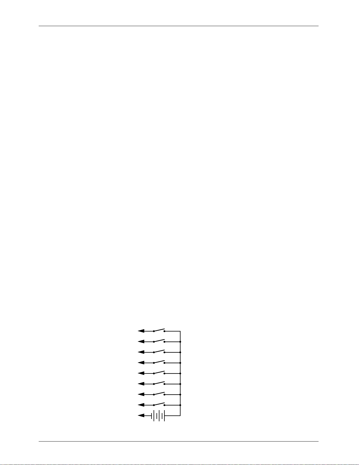
4) 1/4 J-6 input: This is a standard optically isolated 1/4 J-6 input which can be used to randomly
access shows in the Smart Brick System. This input can be configured to operate in one of two
ways. The first of these is a Ôone-of-eightÕ, in which each of the inputs can be used to select
any of the first eight shows in the system (bit 0 selects show #1, bit 1 selects show #2, etc.).
The second operation mode is used when you need to randomly access more than the first
eight shows. In this mode you send the port a binary number to select any of the 63 possible
shows stored in the system. The pin out for the 1/4 J-6 is as follows:
PIN #1
PIN #2
PIN #3
PIN #4
PIN #5
PIN #6
PIN #7
PIN #8
PIN #9
PIN #10
GROUND (not used)
DATA BIT 7
DATA BIT 6
DATA BIT 5
DATA BIT 4
DATA BIT 3
DATA BIT 2
DATA BIT 1
DATA BIT 0
+ 5 to 24 VDC SUPPLY
9 of 134
Page 20
+
GILDERFLUKE & CO.¥ 205 S. FLOWER ST.¥ BURBANK, CA 91502 ¥ 818/840-9484 ¥ 800/776-5972 ¥ FAX 818/840-9485
¥¥¥¥¥¥¥¥¥¥¥¥¥¥¥¥¥¥¥¥¥¥¥¥¥¥¥¥¥¥¥¥¥¥¥¥¥¥¥¥¥¥¥¥¥¥¥¥¥¥¥¥¥¥¥¥¥¥¥¥¥¥¥¥¥¥¥¥¥¥¥¥¥¥¥¥¥¥¥¥¥¥¥¥¥¥¥¥¥¥¥¥¥¥¥¥¥¥¥¥¥¥¥¥¥¥¥¥¥¥¥¥¥¥¥¥¥¥¥
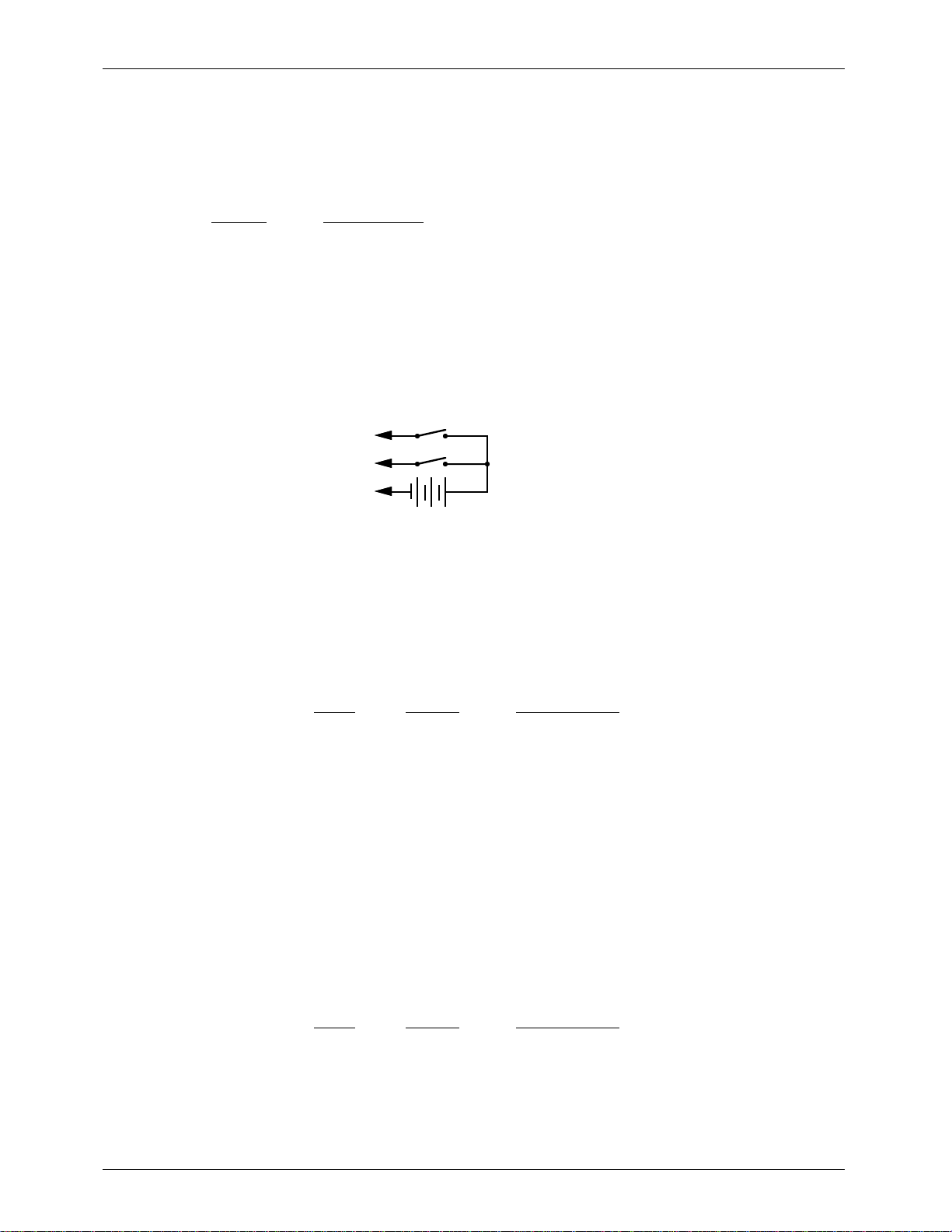
5) J-8 input: This input has two optically isolated inputs on it which can be used for starting, stop-
ping, stepping, resetting, or a variety of other functions in the system.The exact function of
these inputs is set when you configure the Smart Brick Brain. This input has the same pinout
and polarity as the J-8 connections found on all of our normal Micro MACs Bricks. Facing the
end of the plug with the latch upward, the order of these inputs is as follows:
COLOR SIGNAL NAME:
1) WHITE: not used
2) BLACK: common + 5 to 24 VDC (15 Volts nominal) input
3) RED: not used
4) GREEN: optically isolated input
5) YELLOW: not used
6) BLUE: optically isolated input
The Connections to the J-8 input are as follows. As these are feeding into an optoisolator,
you must provide a voltage to the Brick Brain on the BLACK input line (#2):
GREEN #4
BLUE #6
BLACK #2
+ 5 to 24 VDC SUPPLY
¥¥¥¥¥¥¥¥¥¥¥¥¥¥¥¥¥¥¥¥¥¥¥¥¥¥¥¥¥¥¥¥¥¥¥¥¥¥¥¥¥¥¥¥¥¥¥¥¥¥¥¥¥¥¥¥¥¥¥¥¥¥¥¥¥¥¥¥¥¥¥¥¥¥¥¥¥¥¥¥¥¥¥¥¥¥¥¥¥¥¥¥¥¥¥¥¥¥¥¥¥¥¥¥¥¥¥¥¥¥¥¥¥¥¥¥¥¥¥
6) J-8 output: Not used
¥¥¥¥¥¥¥¥¥¥¥¥¥¥¥¥¥¥¥¥¥¥¥¥¥¥¥¥¥¥¥¥¥¥¥¥¥¥¥¥¥¥¥¥¥¥¥¥¥¥¥¥¥¥¥¥¥¥¥¥¥¥¥¥¥¥¥¥¥¥¥¥¥¥¥¥¥¥¥¥¥¥¥¥¥¥¥¥¥¥¥¥¥¥¥¥¥¥¥¥¥¥¥¥¥¥¥¥¥¥¥¥¥¥¥¥¥¥¥
7) To Smart Bricks: This is the start of the cable which runs to all of the Smart Bricks and Heads
Up Displays installed in the system. All signals are compatible with RS-422 and RS-485 signal
levels. Facing the end of the plug with the latch upward, the order of these outputs is as follows:
pin # COLOR SIGNAL NAME:
(left) 1 WHITE + data output
2 BLACK - data output
3 RED + clock output
4 GREEN - clock output
5 YELLOW + strobe output
(right) 6 BLUE - strobe output
¥¥¥¥¥¥¥¥¥¥¥¥¥¥¥¥¥¥¥¥¥¥¥¥¥¥¥¥¥¥¥¥¥¥¥¥¥¥¥¥¥¥¥¥¥¥¥¥¥¥¥¥¥¥¥¥¥¥¥¥¥¥¥¥¥¥¥¥¥¥¥¥¥¥¥¥¥¥¥¥¥¥¥¥¥¥¥¥¥¥¥¥¥¥¥¥¥¥¥¥¥¥¥¥¥¥¥¥¥¥¥¥¥¥¥¥¥¥¥
8) RS-422 Serial Port: This is the serial port which is used to send commands to the Smart Brick
System or to connect a LaserDisk to the Smart Brick System. It must be connected to a terminal or computer running a modem or terminal emulation program for configuring the Smart
Brick System. This is the same style of connector and pin out as is used on the AB-100 Digital
Audio Repeaters, and can be attached to both Brick Brains and Digital Audio Repeaters simultaneously, just so long as their addresses donÕt conflict. Facing the end of the cable with the
release latch upwards, its pin out is as follows:
pin # COLOR SIGNAL NAME:
(left) 1 WHITE signal ground
2 BLACK - serial data out from Brick Brains
3 RED + serial data out from Brick Brains
4 GREEN - serial data in to Brick Brains
5 YELLOW + serial data in to Brick Brains
(right) 6 BLUE signal ground
10 of 134
Page 21
GILDERFLUKE & CO.¥ 205 S. FLOWER ST.¥ BURBANK, CA 91502 ¥ 818/840-9484 ¥ 800/776-5972 ¥ FAX 818/840-9485
To cross wire the RS-422 / RS-485 signals from the Smart Brick System to the RS-232 serial
port of an IBM compatible or Pioneer LaserDisk player, cross connect the signals as follows:
IBM IBM Pioneer LaserDisk
DB-25 DE-9 DB-15 SIGNAL SIGNAL FROM/TO BRICK BRAIN
2 3 2 DATA OUT - serial data in to Brick Brain (GREEN)
3 2 3 DATA IN - serial data out from Brick Brain (BLACK)
7 5 1, 11 or 15 GROUND signal ground (BLUE or WHITE)
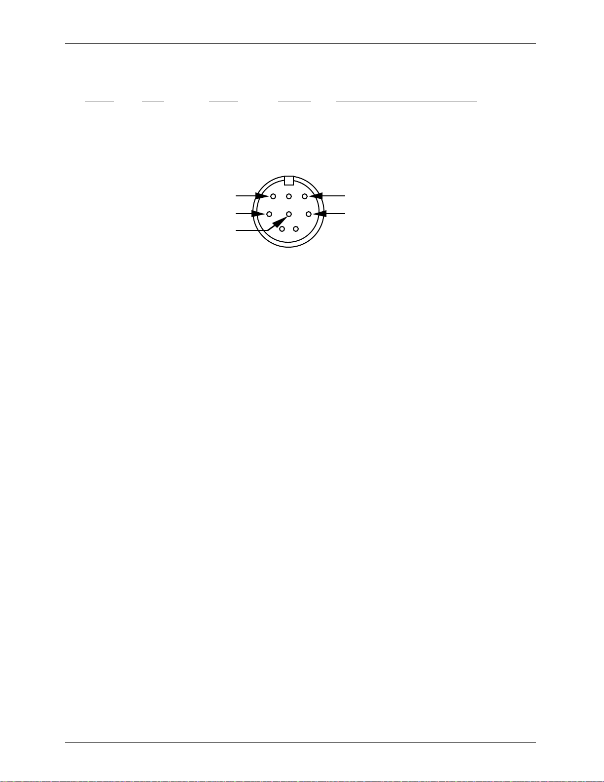
Apple Macintosh computers have true RS-422 serial ports built in. To connect to the Smart
Brick System, the pin out is as follows for a Macintosh mini-DIN-8:
to + serial data in to card (#5 yellow)
to - serial data in to card (#4 green)
signal ground (#1 blue or #6 white)
678
345
12
from + serial data out from card (#3 red)
from - serial data out from card (#2 black)
11 of 134
Page 22
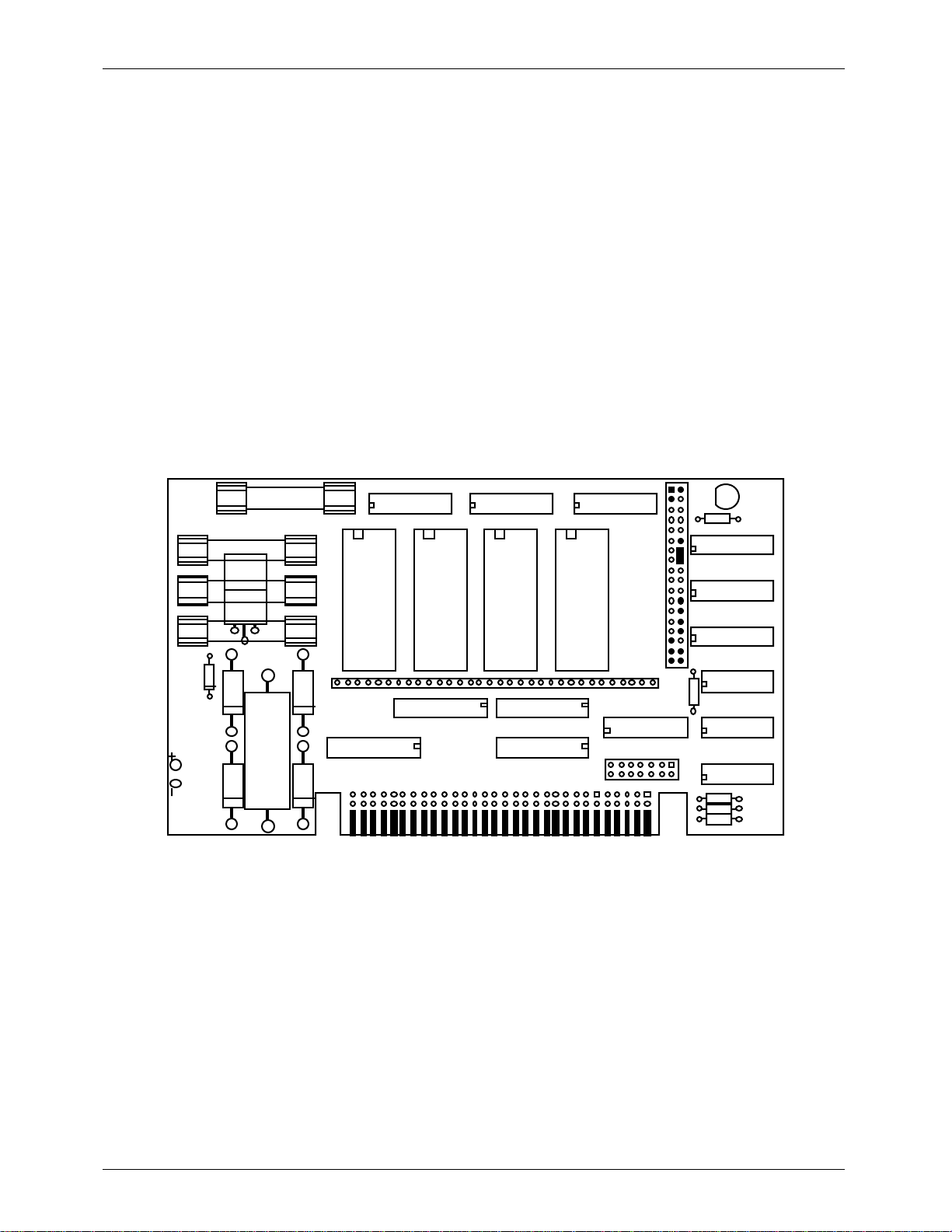
U
F
F
F
F
-
GILDERFLUKE & CO.¥ 205 S. FLOWER ST.¥ BURBANK, CA 91502 ¥ 818/840-9484 ¥ 800/776-5972 ¥ FAX 818/840-9485
- Smart Brick Configuration -
The majority of the configuration for the Smart Bricks is handled in the Brick Brain. The exceptions to
this are those jumpers which set the size and type of memory used in each Smart Brick, and whether or
not you would like the outputs from a Smart Brick to be disabled when ever the system is not advancing
frames.
The one jumper which the Smart Bricks have on them retain the same callout as are used in the normal Micro MACs Bricks. All configuration is done on JP-2. The two things which Smart Bricks must be configured for are the memory size and type and the Ôenable/disable when stoppedÕ.
In all of the following drawings, the jumper pins are shown as circles contained within an outline of
the header assembly. Pins which are used for a given configuration are shown as filled-in, while those
which remain hollow are not being used. The jumper plugs (used for connecting adjacent pins)or wires
(used for connecting pins which are not adjacent) which connect the pins are shown as black lines. Any
pin which is shown filled in with black, but which does not have any wire or jumper plug shown on it,
must have all wires and/or jumper plugs removed from it in the actual Smart Brick you are configuring.
- 6264LP RAM -
To configure a Record/Playback Smart Brick for use with 6264LP static RAM Chips for a
capacity of 16,384 (16K) frames.
4
3
2
4U
1
channel channel channel channel
1U
32
5U
11U
6U
U2
7U
U3121U
41U
3U
2
PJ
01
8
3-PJ
71U
LED
9U
01U
51U
61U
81U
91U
12 of 134
Page 23
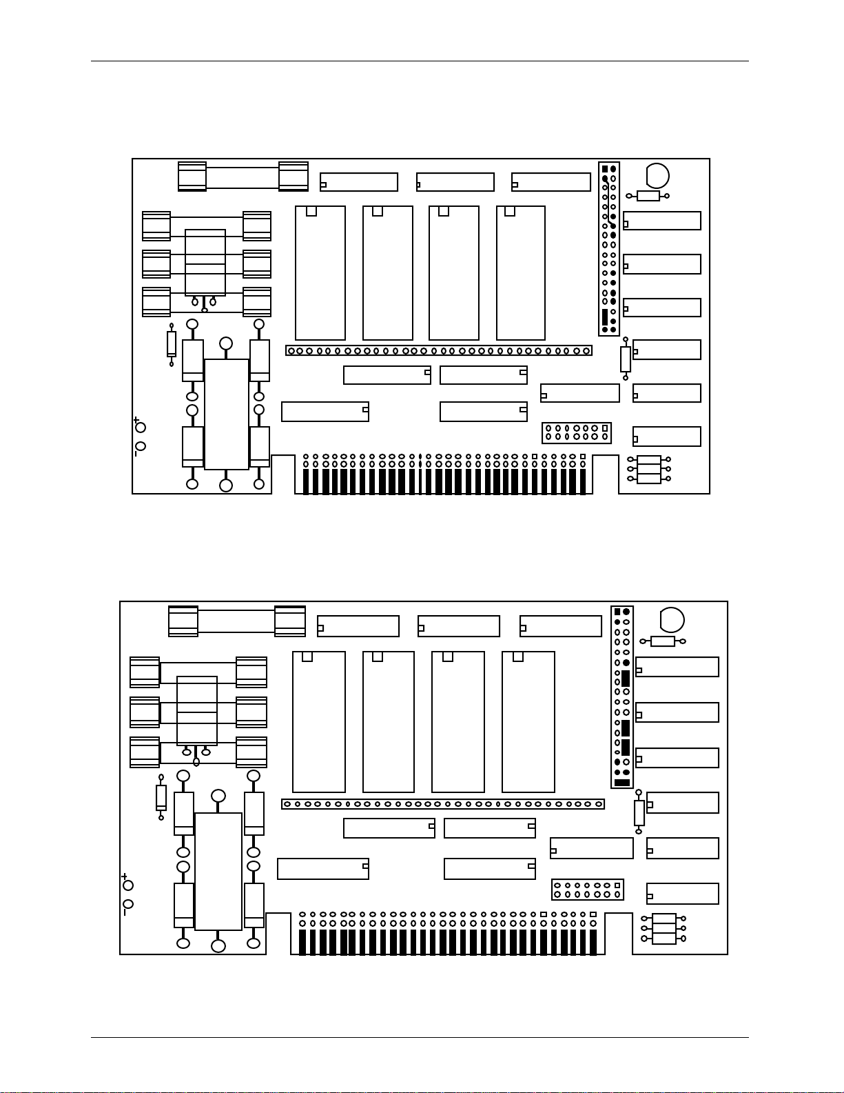
U
8
2
3
U
U
7
3
01U
51U
6
8
9
U
U
U3121U
2
3
GILDERFLUKE & CO.¥ 205 S. FLOWER ST.¥ BURBANK, CA 91502 ¥ 818/840-9484 ¥ 800/776-5972 ¥ FAX 818/840-9485
- 62256LP RAM -
To configure a Record/Playback Smart Brick for use with 62256LP static RAM Chips for a
capacity of 65,536 (64K). (This is the only configuration which requires a wire wrapped
jumper between two pins which arenÕt adjacent.
4F
3F
2F
4U
1F
channel channel channel channel
32
1U
5U
11U
6U
U2
3U
2-PJ
01
7U
U3121U
8U
3-PJ
71U
41U
- 27C32 Eprom -
To configure a Playback-only Smart Brick for use with 27C32 Eprom Chips for a capacity
of 4096 (4K) frames.
LED
9U
01U
51U
61U
81U
91U
4F
F
F
4
1F
channel channel channel channel
32
1U
5
11
6U
U2
U
41
U
-PJ
01
U
-PJ
71
LED
9U
1U
1U
1U
13 of 134
Page 24

U
8
2
3
U
U
7
3
01U
51U
6
8
9
U
U
U3121U
2
3
U
8
2
3
U
U
7
3
01U
51U
6
8
9
U
U
U3121U
2
3
GILDERFLUKE & CO.¥ 205 S. FLOWER ST.¥ BURBANK, CA 91502 ¥ 818/840-9484 ¥ 800/776-5972 ¥ FAX 818/840-9485
- 27C64 Eprom -
To configure a Playback-only Smart Brick for use with 27C64 Eprom Chips for a capacity
of 8192 (8K) frames.
4F
F
F
4
1F
channel channel channel channel
32
1U
5
11
6U
U2
U
41
U
-PJ
01
U
-PJ
71
LED
9U
1U
1U
1U
- 27C128 Eprom -
To configure a Playback-only Smart Brick for use with 27C128 Eprom Chips for a capacity of 16,384 (16K) frames.
4F
F
F
4
1F
channel channel channel channel
32
1U
5
11
6U
U2
U
41
U
-PJ
01
U
-PJ
71
LED
9U
1U
1U
1U
14 of 134
Page 25
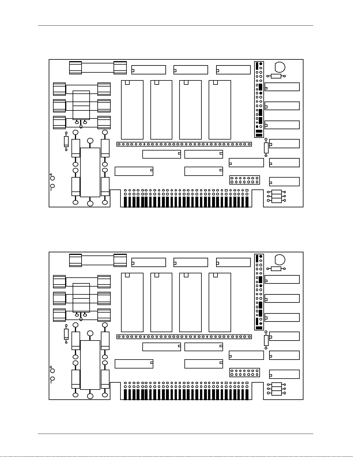
U
8
2
3
U
U
7
3
01U
51U
6
8
9
U
U
U3121U
2
3
U
8
2
3
U
U
7
3
01U
51U
6
8
9
U
U
U3121U
2
3
GILDERFLUKE & CO.¥ 205 S. FLOWER ST.¥ BURBANK, CA 91502 ¥ 818/840-9484 ¥ 800/776-5972 ¥ FAX 818/840-9485
- 27C256 Eprom -
To configure a Playback-only Smart Brick for use with 27C256 Eprom Chips for a capacity of 32,768 (32K) frames.
4F
F
F
4
1F
channel channel channel channel
32
1U
5
11
6U
U2
U
41
U
-PJ
01
U
-PJ
71
LED
9U
1U
1U
1U
- 27C512 Eprom -
To configure a Playback-only Smart Brick for use with 27C512 Eprom Chips for a capacity of 65,536 (64K) frames
4F
F
F
4
1F
channel channel channel channel
32
1U
5
11
6U
U2
U
41
U
-PJ
01
U
-PJ
71
LED
9U
1U
1U
1U
15 of 134
Page 26
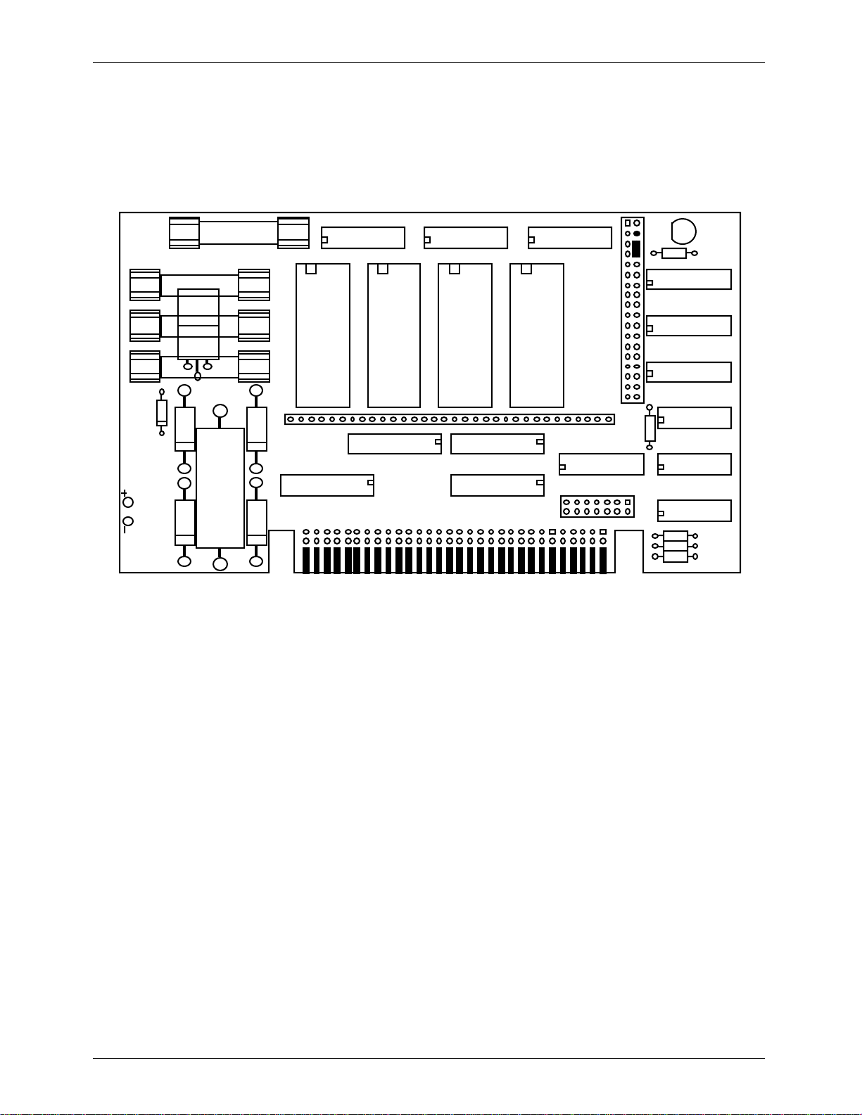
U
8
2
3
U
U
7
3
01U
51U
6
8
9
U
U
U3121U
2
3
GILDERFLUKE & CO.¥ 205 S. FLOWER ST.¥ BURBANK, CA 91502 ¥ 818/840-9484 ¥ 800/776-5972 ¥ FAX 818/840-9485
- Enabling the Outputs When Stopped -
This jumper plug must be installed for the Smart Brick to work. It has two possible positions. This position should be used if you want the outputs to be active at their programmed
levels, even when the system is not advancing frames. This is used if you donÕt care that
some outputs might stay on even when the system is no longer advancing frames. It is almost always used if there are any analog functions attached to a Smart Brick, as disabling
the outputs which feed a D/A converter would cause it to slam to one of itÕs extremes.
4F
F
F
4
1F
channel channel channel channel
32
1U
5
11
6U
U2
U
41
U
-PJ
01
U
-PJ
71
LED
9U
1U
1U
1U
16 of 134
Page 27
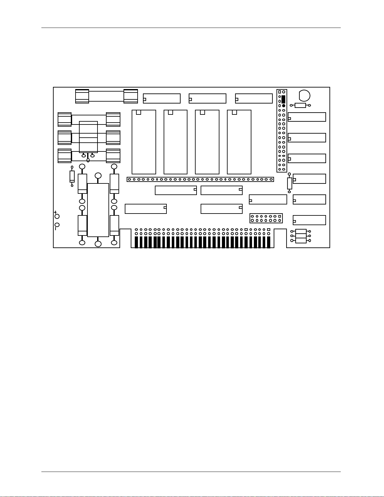
U
8
2
3
U
U
7
3
01U
51U
6
8
9
U
U
U3121U
2
3
GILDERFLUKE & CO.¥ 205 S. FLOWER ST.¥ BURBANK, CA 91502 ¥ 818/840-9484 ¥ 800/776-5972 ¥ FAX 818/840-9485
- Disabling the Outputs When Stopped -
This jumper plug must be installed for the Smart Brick to work. It has two possible positions. This position will cause all of the outputs to turn off whenever the Smart Brick System
stops advancing frames and the Ôrunning delayÕ counter has run out. This is useful if damage might result from leaving certain outputs in your system turned on indefinitely, as could
occur if the system were stopped while those outputs were active.
4F
F
F
4
1F
channel channel channel channel
32
1U
5
11
6U
U2
U
41
U
-PJ
01
U
-PJ
71
LED
9U
1U
1U
1U
17 of 134
Page 28

GILDERFLUKE & CO.¥ 205 S. FLOWER ST.¥ BURBANK, CA 91502 ¥ 818/840-9484 ¥ 800/776-5972 ¥ FAX 818/840-9485
This page was left blank too
18 of 134
Page 29
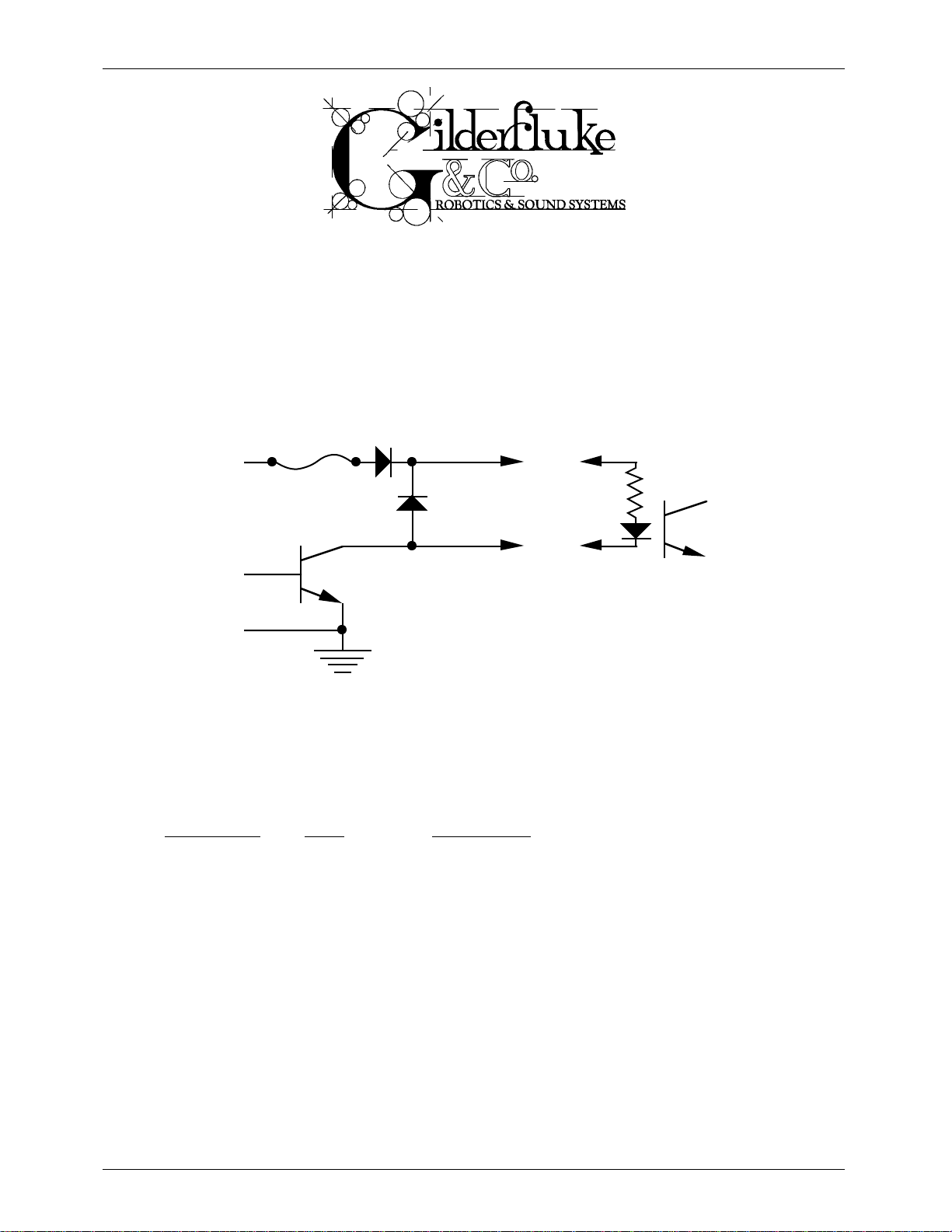
GILDERFLUKE & CO.¥ 205 S. FLOWER ST.¥ BURBANK, CA 91502 ¥ 818/840-9484 ¥ 800/776-5972 ¥ FAX 818/840-9485
- J-6 Digital Output Cables -
In all animation systems made by Gilderfluke & Company all input and output cabling on the Smart
Bricks is through what we call ÔJ-6Õ standard output cables. These are 40 wire cables which are made up
of four identical eight bit wide ÔchannelsÕ. A J-6 cable is often split up into four individual channels. As
each channel also includes a common power supply and ground wire, each Ô1/4 J-6Õ cable is made up
of 10 wires, and can be used to control eight individual ÔdigitalÕ (off/on) devices, or one eight bit wide
ÔanalogÕ device.
In all animation systems made by Gilderfluke & Company, all outputs are open collector switches to
ground, and all inputs are opto isolators. Flyback diodes are included in the outputs for driving inductive
loads:
fuse
flyback
supply supply
diode
typical output
typical input
To simplify wiring to any MACs animation system, the connectors used on the J-6 cables are what
are called Ôinsulation displacement connectorsÕ. These simply snap on to an entire cable, automatically
ÔdisplacingÕ the wire insulation and making contact with the wires within. This means that an entire 40
wire cable can be terminated in seconds. All connectors are polarized, to keep them from being
plugged in backwards. Although there are tools made specifically for installing these connectors, the
tool we find works best is a small bench vise.
Each J-6 cable is arranged in the following order:
wire number color wire function
1 brown circuit ground
2 red channel 0 data bit 7
3 orange channel 0 data bit 6
4 yellow channel 0 data bit 5
5 green channel 0 data bit 4
6 blue channel 0 data bit 3
7 violet channel 0 data bit 2
8 gray channel 0 data bit 1
9 white channel 0 data bit 0
10 black +15 VDC unregulated power supply (fused for 1 amp)
11 brown circuit ground
12 red channel 1 data bit 7
13 orange channel 1 data bit 6
14 yellow channel 1 data bit 5
15 green channel 1 data bit 4
16 blue channel 1 data bit 3
19 of 134
Page 30
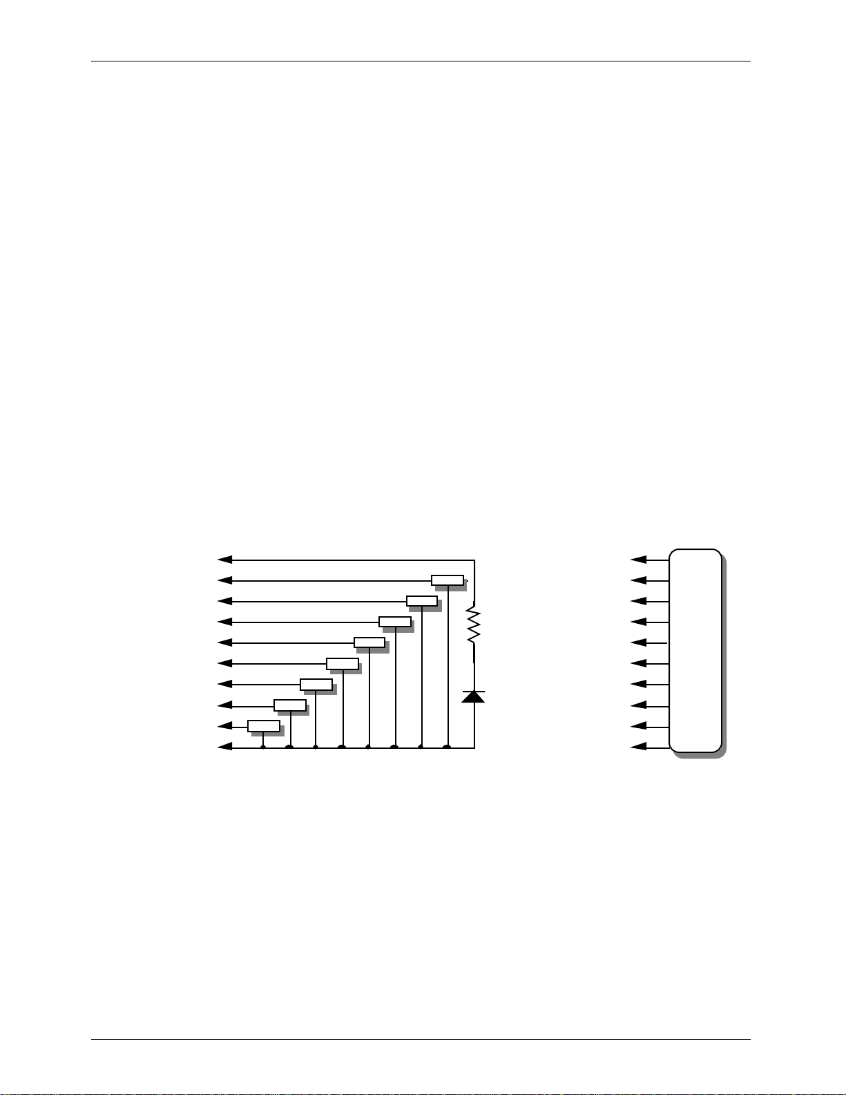
-
-
d
d
d
d
-
GILDERFLUKE & CO.¥ 205 S. FLOWER ST.¥ BURBANK, CA 91502 ¥ 818/840-9484 ¥ 800/776-5972 ¥ FAX 818/840-9485
17 violet channel 1 data bit 2
18 gray channel 1 data bit 1
19 white channel 1 data bit 0
20 black +15 VDC unregulated power supply (fused for 1 amp)
21 brown circuit ground
22 red channel 2 data bit 7
23 orange channel 2 data bit 6
24 yellow channel 2 data bit 5
25 green channel 2 data bit 4
26 blue channel 2 data bit 3
27 violet channel 2 data bit 2
28 gray channel 2 data bit 1
29 white channel 2 data bit 0
30 black +15 VDC unregulated power supply (fused for 1 amp)
31 brown circuit ground
32 red channel 3 data bit 7
33 orange channel 3 data bit 6
34 yellow channel 3 data bit 5
35 green channel 3 data bit 4
36 blue channel 3 data bit 3
37 violet channel 3 data bit 2
38 gray channel 3 data bit 1
39 white channel 3 data bit 0
40 black +15 VDC unregulated power supply (fused for 1 amp)
Any eight digital devices or one eight bit analog device can be connected to any 1/4 J-6 cable as
shown. The LED between the ground (pin #1 brown) wire and supply (pin #10 black) wire acts as an indicator which is lit if the fuse for that channel is OK:
#1 ground (brown)--
#2 bit 7 (red)--
#3 bit 6 (orange)--
#4 bit 5 (yellow)--
#5 bit 4 (green)--
#6 bit 3 (blue)--
#7 bit 2 (violet)--
#8 bit 1 (grey)-
#9 bit 0 (white)--
#10 supply (black)-
load
load
load
load
loa
loa
loa
loa
2.2 K ohm
LED
#1 ground (brown)--
#2 bit 7 (red)--
#3 bit 6 (orange)--
#4 bit 5 (yellow)--
#5 bit 4 (green)--
1/4 watt resistor
#6 bit 3 (blue)--
#7 bit 2 (violet)--
#8 bit 1 (grey)--
#9 bit 0 (white)--
#10 supply (black)-
any
eight bit
analog
device
The supply line for each 1/4 J-6 is fused for 1 amp. You should treat each 1/4 J-6 as an individual,
and not cross the outputs or supply lines from one channel to the lines from any other channel. Doing
this wonÕt cause any damage, but can reduce the protection for the outputs that the fuses normally
provide.
20 of 134
Page 31

y Cy
GILDERFLUKE & CO.¥ 205 S. FLOWER ST.¥ BURBANK, CA 91502 ¥ 818/840-9484 ¥ 800/776-5972 ¥ FAX 818/840-9485
The current Output Capacity of a each output is as shown in the following chart:
Peak Collector Current as a function
600ma.
500ma.
400ma.
300ma.
200ma.
Allowable Peak Collector Current @ 70ºC
100ma.
Number of outputs
conducting
simultaneously
of Output Duty Cycle
6
7
8
2
3
4
5
10% 20% 30% 40% 50% 60% 70% 80% 90%
Output Dut
cle
100%
Since it is unusual to have more than 50% of the outputs on at any one time, you can usually assume the system has a 250 ma output current capacity. If you are going to be turning on lots of heavy
loads at the same time, you should derate this to 150 ma.. This is sufficient to drive the majority of loads
which will be directly connected to the outputs of the animation system. If additional current capacity is
needed, or if you need to drive higher voltage loads, you can connect relays as needed to the outputs
of the animation system. Coincidentally, boards for doing this are available from Gilderfluke &
Company. These include:
DPDT relay board: A set of eight electromechanical relays with double pole/double throw con-
tacts rated at 5 amps each.
Reed relay board: A set of eight small electromechanical relays with normally open contacts
rated at 150 ma each.
I/O module: A set of eight small solid state relays with normally open contacts rated at 3.5 amps
each (AC and DC relays available).
Solid State Relay Fanning Strip: For connecting up to eight popular Ôhockey puckÕ style relays to a
1/4 J-6 output cable. These are available with capacities of up to 75 amps each.
21 of 134
Page 32

GILDERFLUKE & CO.¥ 205 S. FLOWER ST.¥ BURBANK, CA 91502 ¥ 818/840-9484 ¥ 800/776-5972 ¥ FAX 818/840-9485
This page was left blank too
22 of 134
Page 33

GILDERFLUKE & CO.¥ 205 S. FLOWER ST.¥ BURBANK, CA 91502 ¥ 818/840-9484 ¥ 800/776-5972 ¥ FAX 818/840-9485
- Programming -
Every Smart Brick has a capacity which is 32 bits wide. When controlling digital (on/off) functions,
each of these 32 outputs can be used to turn on and off a single device. At eight bits of resolution,
each analog (variable speed and position) function takes over eight of these digital outputs. Any combination of digital and analog functions can be controlled from a single Smart Brick. With eight bit resolution analog functions, the following show all the possible combinations:
A) no analogs and 32 digital functions
B) 1 analog and 24 digital functions
C) 2 analogs and 16 digital functions
D) 3 analogs and 8 digital functions
E) 4 analogs and no digital functions
Playback-Only Bricks:
All Playback-only Smart Bricks have their data stored in Eproms. Burning data into Eproms is as close
to Ôchiseling in stoneÕ as you can get in the world of computers. Short of being hit by lightning, anything
which is programmed into one of these playback-only Bricks will last forever (unless you want to change
it). The Eproms are programmed outside the bricks and then plugged into them. The program can be
generated in one of several ways:
A) The show is initially programmed using standard record-playback bricks. When the program-
ming is completed, the show data is moved to an IBM compatible computer using the IBM
Backup Box. It can then be burned into the Eproms using any commercially available Eprom
programmer.
B) The show is initially programmed using a full-sized MACs Animation Control System and then
burned into the Eproms using any commercially available Eprom programmer
C) The show is initially programmed from any other source and then burned into the Eproms
using any commercially available Eprom programmer.
Record-Playback Bricks:
The only bricks which can be programmed directly are the record-playback bricks. Shows for these
can also be programmed using ours or just about any other full-sized Animation Control System, and
then downloaded to the record-playback Smart Bricks.
All Smart Bricks are real-time Animation Control Systems. What this means is that they are normally
programmed as the show is going on. You do this by moving the controls (pots, joysticks, buttons, sliders,
or whatever) which are connected to the figure through the control system and watching it move as the
audio for the show (if any) is played. The bricks will remember exactly whatever you do on the controls
and when you did it. Once programmed, this data will stay in the bricks until you want to change it
again.
Normally only one or two functions are programmed at a time. On each pass through the show you
add the programming for few additional channels while all previously recorded channels play back
whatever you have already programmed into them. If you make a mistake on any pass, you can always
go back and change the programming for the whole show, or just the area where it needs it. By repeating this process, you eventually have all of the movements programmed! It is exactly like building up a
multi track recording in an audio studio.
Once programmed, the programming hardware can then be removed from the system.
23 of 134
Page 34

GILDERFLUKE & CO.¥ 205 S. FLOWER ST.¥ BURBANK, CA 91502 ¥ 818/840-9484 ¥ 800/776-5972 ¥ FAX 818/840-9485
This programming hardware can be a standard Micro Console, or a console which has been made
for your specific requirements. Additional optional hardware which can be used during programming are
the IBM Backup Box and Heads-Up-Displays. The IBM Backup Box (with an IBM PC or compatible) can be
used to random access specific frames within a show, program Ôsingle stepÕ on a frame-by-frame basis,
or store a completed animation sequence to the disk of the IBM for archival use or burning into the
Eproms which are plugged into the playback-only Smart Bricks. The Heads-Up-Display simply gives you a
big readout to tell you where in a show you are at any instant.
Each Micro Console can be used to program one brick at a time. If more than one brick is used in
your show, then you can move the console between the bricks as they are programmed, or use more
than one console. The Micro Console has individual momentary and sustained switches for each of the
32 BricksÕ possible outputs, as well as four pots for programming up to 4 eight bit analog functions. A
Micro Console is attached to a Smart Brick as shown. Two cables run between the Micro Console and
the Smart Brick while a third cable goes to whatever the system is controlling. After programming is completed, this third cable is plugged directly into the Smart BrickÕs ÔoutputÕ connector.
rec./play Brick
from out to in
Micro Console
When building a programming console specific to your application, you can make it as simple or as
complicated as you desire. Where a standard Micro Console can handle up to four 8 bit wide channels
at one time, you can build your console to allow you to program just as many channels at a time as you
want.
All that is required for programming a digital function is a simple switch for each brick output/input:
to your show
SPDT
(center off)
switch
(on)
off
to brick input
play
+15V
from brick output
to show
24 of 134
Page 35

GILDERFLUKE & CO.¥ 205 S. FLOWER ST.¥ BURBANK, CA 91502 ¥ 818/840-9484 ¥ 800/776-5972 ¥ FAX 818/840-9485
By adding a pushbutton switch to the connections shown above, you can make an easier to use
programming console that has a separate Ôprogramming enableÕ switch and pushbutton for turning on
and off the output
momentary
programing
switch
SPDT
switch
rec.
to brick input
play
+15V
from brick output
For building an analog programming console, we recommend you use our Analog to Digital (A/D)
Converters. One is used for each analog function on your console. In this case the wires Ôfrom brick outputÕ, Ôto brick inputÕ, and Ôto showÕ are actually eight wires (plus ground and + supply) that make up a 1/4
J-6 cable:
potentiometer
to show
SPST
sw i tch
playback
rec ord analog
from bri ck out put
A/ D
to bric k i nput
to show
25 of 134
Page 36

GILDERFLUKE & CO.¥ 205 S. FLOWER ST.¥ BURBANK, CA 91502 ¥ 818/840-9484 ¥ 800/776-5972 ¥ FAX 818/840-9485
The following shows the entire wiring diagram for a simple digital-only programming console for one
eight bit channel. Channel 0 pinouts shown on the 1/4 J-6 connectors. Add 10 to all pin numbers for
channel 1, 20 for channel 2, and 30 for channel 3. All switches are Single Pole, Double Throw (SPDT)
center off, (optionally momentary one side only). Rear view of actual switches is shown.
+15 VDC from MICRO MACs Output pin #10 (black) +15 VDC to MICRO MACs Input pin #10 (black)
+15 VDC to your show connector pin #10 (black)
to MICRO MACs Input pin #9 (white)
to your show connector pin #9 (white)
to MICRO MACs Input pin #8 (grey)
to your show connector pin #8 (grey)
to MICRO MACs Input pin #7 (violet)
to your show connector pin #7 (violet)
LED (fuse indicator - lit if fuse is OK)
from MICRO MACs Output pin #9 (white)
Programming Switch For
Channel 0, Bit 0
from MICRO MACs Output pin #8 (grey)
Programming Switch For
Channel 0, Bit 1
from MICRO MACs Output pin #7 (violet)
Programming Switch For
Channel 0, Bit 2
2.2 K
resistor
playback
off
(on)
playback
off
(on)
playback
off
LED
2.2 K resistor
LED
2.2 K resistor
LED
2.2 K resistor
from MICRO MACs Output pin #6 (blue)
Programming Switch For
Channel 0, Bit 3
from MICRO MACs Output pin #5 (green)
Programming Switch For
Channel 0, Bit 4
from MICRO MACs Output pin #4 (yellow)
Programming Switch For
Channel 0, Bit 5
from MICRO MACs Output pin #3 (orange)
Programming Switch For
Channel 0, Bit 6
(on)
playback
off
(on)
playback
off
(on)
playback
off
(on)
playback
off
LED
2.2 K resistor
to MICRO MACs Input pin #6 (blue)
to your show connector pin #6 (blue)
LED
2.2 K resistor
to MICRO MACs Input pin #5 (green)
to your show connector pin #5 (green)
LED
2.2 K resistor
to MICRO MACs Input pin #4 (yellow)
to your show connector pin #4 (yellow)
LED
2.2 K resistor
to MICRO MACs Input pin #3 (orange)
to your show connector pin #3 (orange)
from MICRO MACs Output pin #2 (red)
Programming Switch For
Channel 0, Bit 7
ground from MICRO MACs Output pin #1 (brown)
(on)
playback
off
(on)
26 of 134
LED
2.2 K resistor
to MICRO MACs Input pin #2 (red)
to your show connector pin #2 (red)
ground to your show connector pin #1 (brown)
ground to MICRO MACs Input pin #1 (brown)
Page 37

GILDERFLUKE & CO.¥ 205 S. FLOWER ST.¥ BURBANK, CA 91502 ¥ 818/840-9484 ¥ 800/776-5972 ¥ FAX 818/840-9485
- Smart Brick System Commands -
The MACs Smart Brick System can be controlled by simple switch closures to start and stop playback
or cycling, randomly select shows, and perform a variety of functions. In addition to this method of controlling it, you can talk to any combination of up to 256 Smart Brick Systems and Digital Audio Repeaters
at one time through a serial data line from your computer, terminal, or control system.
This same serial port must be used to configure the features of any Smart Brick System, and is used
by the system when it needs to talk to a LaserDisk player or any other serially controlled device. The latter
limits the use of the serial port to those systems which are not controlling LaserDisk players.
All commands sent to the MACs Smart Brick System through its serial interface take the following format. All characters are sent in ASCII. All numeric values are sent in HEXadecimal (HEX for short), and
consist of one or more ASCII characters (0-9, A through F). The case (as in upper and lower) of all input is
important. A lower case 'a' signifies a command, while an 'A' is a numeric value. If the Smart Brick System
receives another command while it is waiting for additional input needed to complete the previous command, it will abandon the previous command and start working on the new one.
In the following documentation any input you will send to the audio system is shown in outline. The
response to a command is shown in italics.
If the Smart Brick System is in a mode where you expect to receive some response from it (generally
in one of the echo modes), you must wait to receive all of the characters you are expecting before
sending the system a new command. The reason for this is that you are actually talking to up to 256 microprocessors at a time, and if you issue a command which gives a response from one Brick Brain, and
then a command which gives a response from a second Brick Brain before the first has finished, then the
two may try and output data at the same time. This won't cause any damage, but may result in garbled
data at the receiver.
It is also possible to overload the Smart Brick System with too many commands through the serial
port. You don't want to take too much time away from the Brick Brain to service the serial port.
To communicate with the Smart Brick System through the serial port, you can use just about any
computer or terminal which has a serial port on it. Most modern computer designs, like the Apple
Macintosh, come with serial ports which are directly compatible with the RS-422 / RS-485 signal levels
the Smart Brick System wants to see. These signal levels are close enough to be used with the RS-232 signal levels found on most old-fashioned computers (like IBMs and compatibles) with only a simple adapter
cable, so long as the wire isn't too long and you donÕt have too many devices on the same line. To gain
the full advantage of the RS-422 / RS-485 signal levels you will need to use a signal level adapter.
If you are using a computer as a terminal you will need to run a modem or terminal emulation program. Virtually any one should work. These will send everything you type on the keyboard out the serial
port on your computer while printing on the screen anything which comes in from the Brick Brain
through the serial port. A modem program will usually have the advantage over a terminal emulation
program in that it will allow you to save data to your computer's disk drives and then send it back to the
audio system at a later date. The Smart Brick System uses no screen control codes or ESCape sequences, so it will work on any machine with a 80 column by 24 line display. Machines with other display
formats will also work, but may not look so neat on the screen.
When configuring your modem program, you should set it for 9600 baud, 8 data bits, one stop bit,
and no parity. Higher or lower baud rates can be used if you configure the Brick BrainÕs serial port to run
at a different speed. You should set your program not to insert an extra LineFeed (LF) character after
each Carriage Return (CR) it receives. If you are going to be downloading configuration strings to the
system (command ÔsÕ), you will also need to tell the modem program to put a slight delay between each
character sent in order to not over run the Brick BrainÕs incoming data buffer.
27 of 134
Page 38

GILDERFLUKE & CO.¥ 205 S. FLOWER ST.¥ BURBANK, CA 91502 ¥ 818/840-9484 ¥ 800/776-5972 ¥ FAX 818/840-9485
If you have hooked up the Brick Brain to your computer and it still doesnÕt seem to respond to the
keyboard, the first thing to check is that you are attached to the correct serial port. The easiest way to
check this is to disconnect the Brick Brain and short between the Tx data out and Rx data in pins on the
serial port connector on the back of your computer. On all IBMs and compatibles this means sticking a
paper clip or similar tool between pins 2 and 3 on the ÔCom.Õ connector. While still running the modem
program, anything you type should be shown on the screen while this paper clip is in place, while nothing will appear when you remove it. If your computer passes this test, then you are using the right serial
port and the problem is most likely the baud rate setting or in your wiring to the Brick Brain. If you get
characters on the screen even with the paper clip removed from the serial port, it means you probably
need to set the ÔechoÕ mode to ÔnoneÕ or Ôfull duplexÕ and try this test again.
The Brick Brain uses a 6 position RJ-11 modular telephone style connector for the serial data. This is
the same style of connector and pin out as is used on the AB-100 Digital Audio Repeaters. Facing the
end of the cable with the release latch upwards, its pin out is as follows:
pin # COLOR SIGNAL NAME:
(left) 1) WHITE: signal ground
2) BLACK: - serial data out from Brick Brains
3) RED: + serial data out from Brick Brains
4) GREEN: - serial data in to Brick Brains
5) YELLOW: + serial data in to Brick Brains
(right) 6) BLUE: signal ground
To cross wire the RS-422 / RS-485 signals from the Smart Brick System to the RS-232 serial port of an
IBM compatible or Pioneer LaserDisk player, cross connect the signals as follows:
IBM IBM Pioneer LaserDisk
DB-25 DE-9 DB-15 SIGNAL SIGNAL FROM/TO BRICK BRAIN
2 3 2 DATA OUT - serial data in to Brick Brain (GREEN)
3 2 3 DATA IN - serial data out from Brick Brain (BLACK)
7 5 1, 11 or 15 GROUND signal ground (BLUE or WHITE)
Apple Macintosh computers have true RS-422 serial ports built in. To connect to the Smart Brick
System, the pin out is as follows for a Macintosh mini-DIN-8:
to + serial data in to card (#5 yellow)
to - serial data in to card (#4 green)
signal ground (#1 blue or #6 white)
678
345
12
from + serial data out from card (#3 red)
from - serial data out from card (#2 black)
The Smart Brick System expects to see the serial data in the following format:
ONE START BIT
EIGHT DATA BITS
TWO STOP BITS
If the ODD PARITY is enabled, then the data appears in the following format:
ONE START BIT
SEVEN DATA BITS
ODD PARITY BIT
TWO STOP BITS
When the parity is enabled, any data with a parity error in it is simply ignored.
There are a number of methods which you can use to access a number of Brick Brains and Digital
Audio Repeaters at the same time. If you are controlling the animation and audio systems through the
serial input, you can use any or all of them as best suits your application. They are
1) Global - Any command of this type affects all of the Brick Brains in the system.
EXAMPLE: A 'START GLOBAL' command will start all of the Smart Brick Brains and Digital
Audio Repeaters in the system.
28 of 134
Page 39

GILDERFLUKE & CO.¥ 205 S. FLOWER ST.¥ BURBANK, CA 91502 ¥ 818/840-9484 ¥ 800/776-5972 ¥ FAX 818/840-9485
2) Track Specific - Only the one Brick Brain addressed by the command is affected by this type
of command. Each Brick Brain and Digital Audio Repeater card in the system must be configured to respond to different TRACK NUMBER address in order for the system to operate properly.
EXAMPLE: A 'START TRACK#' command will start only the one Brick Brain or Audio
Repeater card addressed by the TRACK# in the command.
3) Cocked - You can set a flag on any number of different Brick Brains and Audio Repeater
cards in the system which, when set, will cause those cards to respond to commands of this
type. Once a cocked command is issued, the cocked flag on all the cards will be reset.
EXAMPLE: A 'START COCKED' command will start only those Brick Brains and Digital Audio
Repeaters which have had their 'COCKED' flags set by the COCK TRACK# command.
4) Group (Rack Smart Brick Brain only) - Any number of different Rack Smart Brick Brains and
Audio Repeater cards in the system can be set to respond to one of sixteen different ÔGroupsÕ.
Any of the group commands can access any number of cards simultaneously.
EXAMPLE: A 'START GROUP 5' command will start only those Brick Brains and Digital Audio
Repeaters which respond to group number 5.
29 of 134
Page 40

GILDERFLUKE & CO.¥ 205 S. FLOWER ST.¥ BURBANK, CA 91502 ¥ 818/840-9484 ¥ 800/776-5972 ¥ FAX 818/840-9485
- Commands -
ÒaÓ (track#) Enter Interactive Echo Mode:
This command puts the one Brick Brain addressed by the TRACK# into this mode while taking all
other Brick Brains out of this mode. This is a special mode which lets you play with the command structure of the Smart Brick System and get an echo of all commands in plain English. This form of echo
should normally be used only while manually manipulating the system as it can take a relatively long
time to echo the 20 to 30 ASCII characters most commands will return when in this mode. During this response time, no additional commands should be given.
When in this mode, all commands are echoed by the one Brick Brain which was addressed by the
TRACK# used when this mode was entered. This means that any command will be echoed, even if the
command is being sent to a nonexistent Brick Brain.
EXAMPLE: to put Brick Brain 00 into SETUP ECHO mode:
a 0 0
TRACK 00 Setup Mode Selected
EXAMPLE: a 'START GLOBAL' command will echo:
'GLOBAL START'
¥¥¥¥¥¥¥¥¥¥¥¥¥¥¥¥¥¥¥¥¥¥¥¥¥¥¥¥¥¥¥¥¥¥¥¥¥¥¥¥¥¥¥¥¥¥¥¥¥¥¥¥¥¥¥¥¥¥¥¥¥¥¥¥¥¥¥¥¥¥¥¥¥¥¥¥¥¥¥¥¥¥¥¥¥¥¥¥¥¥¥¥¥¥¥¥¥¥¥¥¥¥¥¥¥¥¥¥¥¥¥¥¥¥¥¥¥¥¥
ÒbÓ Exit Interactive Echo Mode:
This command takes all Brick Brains in the system out of SETUP ECHO MODE.
EXAMPLE: to take any and all Brick Brains out of SETUP ECHO mode:
b
¥¥¥¥¥¥¥¥¥¥¥¥¥¥¥¥¥¥¥¥¥¥¥¥¥¥¥¥¥¥¥¥¥¥¥¥¥¥¥¥¥¥¥¥¥¥¥¥¥¥¥¥¥¥¥¥¥¥¥¥¥¥¥¥¥¥¥¥¥¥¥¥¥¥¥¥¥¥¥¥¥¥¥¥¥¥¥¥¥¥¥¥¥¥¥¥¥¥¥¥¥¥¥¥¥¥¥¥¥¥¥¥¥¥¥¥¥¥¥
ÒcÓ (track#) Enter Global Echo Mode:
This command puts the one Brick Brain addressed by the TRACK# into this mode while taking all
other Brick Brains out of it. The one Brick Brain which is in this mode will echo all non-track-specific commands accepted by the system. This type of echo can be used in an automated system to assure that
the Smart Brick System has received any non-track-specific command. Note that since only one Brick
Brain in the system is in this mode at a time, that this form of echo only verifies the operation of this one
Brick Brain and no other parts of the system.
EXAMPLE: to put Brick Brain 00 into GLOBAL ECHO mode:
c 0 0
EXAMPLE: a 'START GLOBAL' command Ôu Õ will echo the actual character used to select it ÔuÕ.
¥¥¥¥¥¥¥¥¥¥¥¥¥¥¥¥¥¥¥¥¥¥¥¥¥¥¥¥¥¥¥¥¥¥¥¥¥¥¥¥¥¥¥¥¥¥¥¥¥¥¥¥¥¥¥¥¥¥¥¥¥¥¥¥¥¥¥¥¥¥¥¥¥¥¥¥¥¥¥¥¥¥¥¥¥¥¥¥¥¥¥¥¥¥¥¥¥¥¥¥¥¥¥¥¥¥¥¥¥¥¥¥¥¥¥¥¥¥¥
ÒdÓ Exit Global Echo Mode:
This command takes all Brick Brains in the system out of GLOBAL ECHO MODE
EXAMPLE: to take any and all Brick Brains out of GLOBAL ECHO mode:
u
¥¥¥¥¥¥¥¥¥¥¥¥¥¥¥¥¥¥¥¥¥¥¥¥¥¥¥¥¥¥¥¥¥¥¥¥¥¥¥¥¥¥¥¥¥¥¥¥¥¥¥¥¥¥¥¥¥¥¥¥¥¥¥¥¥¥¥¥¥¥¥¥¥¥¥¥¥¥¥¥¥¥¥¥¥¥¥¥¥¥¥¥¥¥¥¥¥¥¥¥¥¥¥¥¥¥¥¥¥¥¥¥¥¥¥¥¥¥¥
ÒeÓ (track#) Enter Echo All Mode:
This command puts the one Brick Brain addressed by the TRACK# into this mode while taking all
30 of 134
Page 41

GILDERFLUKE & CO.¥ 205 S. FLOWER ST.¥ BURBANK, CA 91502 ¥ 818/840-9484 ¥ 800/776-5972 ¥ FAX 818/840-9485
other Brick Brains out of this mode. The one Brick Brain which is in ECHO ALL MODE echoes any and all
characters sent to the Brick Brain through the serial port. This type of echo can be used to verify that the
Smart Brick System has received all characters sent to it. Note that since only one Brick Brain in the system is in this mode at a time, that this form of echo only verifies the operation of this one Brick Brain and
no other parts of the system.
EXAMPLE: to put Brick Brain 00 into ECHO GLOBAL mode:
e 0 0
EXAMPLE: a typing random characters ÔapiuryhqpfnhsdflauthfÕ will echo:
apiuryhqpfnhsdflauthf
¥¥¥¥¥¥¥¥¥¥¥¥¥¥¥¥¥¥¥¥¥¥¥¥¥¥¥¥¥¥¥¥¥¥¥¥¥¥¥¥¥¥¥¥¥¥¥¥¥¥¥¥¥¥¥¥¥¥¥¥¥¥¥¥¥¥¥¥¥¥¥¥¥¥¥¥¥¥¥¥¥¥¥¥¥¥¥¥¥¥¥¥¥¥¥¥¥¥¥¥¥¥¥¥¥¥¥¥¥¥¥¥¥¥¥¥¥¥¥
ÒfÓ Exit Echo All Mode:
This command takes all Brick Brains in the system out of ECHO ALL MODE.
EXAMPLE: to take any and all Brick Brains out of ECHO ALL MODE:
f
¥¥¥¥¥¥¥¥¥¥¥¥¥¥¥¥¥¥¥¥¥¥¥¥¥¥¥¥¥¥¥¥¥¥¥¥¥¥¥¥¥¥¥¥¥¥¥¥¥¥¥¥¥¥¥¥¥¥¥¥¥¥¥¥¥¥¥¥¥¥¥¥¥¥¥¥¥¥¥¥¥¥¥¥¥¥¥¥¥¥¥¥¥¥¥¥¥¥¥¥¥¥¥¥¥¥¥¥¥¥¥¥¥¥¥¥¥¥
ÒgÓ Enter Echo Mode:
This command puts all the Brick Brains in the system into ECHO MODE. When in this mode, the char-
acters used to select all track-specific commands are echoed by the Brick Brain addressed by the command. This is the type of echo mode which best verifies the proper operation of all the Brick Brains in the
Smart Brick System.
EXAMPLE: to put Brick Brain 00 into ECHO MODE:
g 0 0
EXAMPLE: a 'START TRACK# 00' command will echo:
t00
¥¥¥¥¥¥¥¥¥¥¥¥¥¥¥¥¥¥¥¥¥¥¥¥¥¥¥¥¥¥¥¥¥¥¥¥¥¥¥¥¥¥¥¥¥¥¥¥¥¥¥¥¥¥¥¥¥¥¥¥¥¥¥¥¥¥¥¥¥¥¥¥¥¥¥¥¥¥¥¥¥¥¥¥¥¥¥¥¥¥¥¥¥¥¥¥¥¥¥¥¥¥¥¥¥¥¥¥¥¥¥¥¥¥¥¥¥¥¥
ÒhÓ Exit Echo Mode:
This command takes all Brick Brains in the system out of ECHO MODE.
EXAMPLE: to take any and all Brick Brains out of ECHO MODE:
h
¥¥¥¥¥¥¥¥¥¥¥¥¥¥¥¥¥¥¥¥¥¥¥¥¥¥¥¥¥¥¥¥¥¥¥¥¥¥¥¥¥¥¥¥¥¥¥¥¥¥¥¥¥¥¥¥¥¥¥¥¥¥¥¥¥¥¥¥¥¥¥¥¥¥¥¥¥¥¥¥¥¥¥¥¥¥¥¥¥¥¥¥¥¥¥¥¥¥¥¥¥¥¥¥¥¥¥¥¥¥¥¥¥¥¥¥¥¥¥
ÒiÓ (track#) Track Status Mode:
This command responds with a stream of ASCII HEX data containing the current status of the Brick
Brain specified by the TRACK#:
BYTE 1 & 2 = BRICK BRAIN STATUS
BIT 0 = STORED START RECEIVED
BIT 1 = CYCLING SHOWS FLAG
BIT 2 = DOING DELAY BETWEEN SHOWS
BIT 3 = DOING SHOW END
BIT 4 = LaserDisk CLOCKED SHOW
BIT 5 = EXTERNALLY CLOCKED SHOW
BIT 6 = SMPTE CLOCKED SHOW
BIT 7 = INTERNALLY CLOCKED SHOW
31 of 134
Page 42

GILDERFLUKE & CO.¥ 205 S. FLOWER ST.¥ BURBANK, CA 91502 ¥ 818/840-9484 ¥ 800/776-5972 ¥ FAX 818/840-9485
BYTE 3= SPACE
BYTE 4 & 5 = INPUT STATUS
BIT 0 = GREEN INPUT STATUS (1 = closed)
BIT 1 = BLUE INPUT STATUS (1 = closed)
BIT 2 = PB INPUT STATUS (1 = closed)
BIT 3 = not used
BIT 4 = THUMBWHEEL SWITCH BIT 0
BIT 5 = THUMBWHEEL SWITCH BIT 1
BIT 6 = THUMBWHEEL SWITCH BIT 2
BIT 7 = THUMBWHEEL SWITCH BIT 3
BYTE 6 = SPACE
BYTE 7 & 8 = CURRENT, OR MOST RECENT SHOW NUMBER
BYTE 9 = SPACE
BYTES 10 through 13 = CURRENT BRICK ADDRESS
BYTE 14 = SPACE
BYTE 15 & 16 = DISPLAY HOURS
BYTE 17 = COLON
BYTE 18 & 19 = DISPLAY MINUTES
BYTE 20 = COLON
BYTE 21 & 22 = DISPLAY SECONDS
BYTE 23 = PERIOD
BYTE 24 & 25 = DISPLAY FRAMES
BYTE 26 = SPACE
BYTE 27 & 28 = DIPSWITCH 1
BYTE 29 = SPACE
BYTE 30 & 31 = J-6 PORT
BYTE 32 = CARRIAGE RETURN
BYTE 33 = LINE FEED
EXAMPLE: to poll the status for Brick Brain 00:
i 0 0
82 10 02 039D 02:00:05.08 30 00
This would tell you that the Brick Brain is running an internally clocked show, that the system is currently cycling shows, that the thumbwheel switch is set to Ô1Õ, the show number is Ô02Õ, the frame being
addressed in the Smart Bricks is 039D, the time into the show is 5.08 seconds, that record is enabled and
we are using 64K Smart Bricks, and that there is no input to the J-6 port.
¥¥¥¥¥¥¥¥¥¥¥¥¥¥¥¥¥¥¥¥¥¥¥¥¥¥¥¥¥¥¥¥¥¥¥¥¥¥¥¥¥¥¥¥¥¥¥¥¥¥¥¥¥¥¥¥¥¥¥¥¥¥¥¥¥¥¥¥¥¥¥¥¥¥¥¥¥¥¥¥¥¥¥¥¥¥¥¥¥¥¥¥¥¥¥¥¥¥¥¥¥¥¥¥¥¥¥¥¥¥¥¥¥¥¥¥¥¥¥
ÒkÓ (track#) Brick Brain Status:
This command responds with the following information for the Brick Brain specified by the TRACK#:
BIT 0 = STORED START RECEIVED
BIT 1 = CYCLING SHOWS FLAG
BIT 2 = DOING DELAY BETWEEN SHOWS
BIT 3 = DOING SHOW END
BIT 4 = LaserDisk CLOCKED SHOW
BIT 5 = EXTERNALLY CLOCKED SHOW
BIT 6 = SMPTE CLOCKED SHOW
BIT 7 = INTERNALLY CLOCKED SHOW
EXAMPLE: to poll the status of the Brick Brain addressed at 00:
k 0 0
40
This would tell you that the Brick Brain is currently running a SMPTE clocked show.
32 of 134
Page 43

GILDERFLUKE & CO.¥ 205 S. FLOWER ST.¥ BURBANK, CA 91502 ¥ 818/840-9484 ¥ 800/776-5972 ¥ FAX 818/840-9485
¥¥¥¥¥¥¥¥¥¥¥¥¥¥¥¥¥¥¥¥¥¥¥¥¥¥¥¥¥¥¥¥¥¥¥¥¥¥¥¥¥¥¥¥¥¥¥¥¥¥¥¥¥¥¥¥¥¥¥¥¥¥¥¥¥¥¥¥¥¥¥¥¥¥¥¥¥¥¥¥¥¥¥¥¥¥¥¥¥¥¥¥¥¥¥¥¥¥¥¥¥¥¥¥¥¥¥¥¥¥¥¥¥¥¥¥¥¥¥
ÒlÓ (track#) Switch Status:
This command responds with the following information for the Brick Brain specified by the TRACK#:
BIT 0 = GREEN INPUT STATUS (1 = closed)
BIT 1 = BLUE INPUT STATUS (1 = closed)
BIT 2 = PB INPUT STATUS (1 = closed)
BIT 3 = not used
BIT 4 = THUMBWHEEL SWITCH BIT 0
BIT 5 = THUMBWHEEL SWITCH BIT 1
BIT 6 = THUMBWHEEL SWITCH BIT 2
BIT 7 = THUMBWHEEL SWITCH BIT 3
EXAMPLE: to poll the input switch status for Brick Brain 00:
l 0 0
31
This would tell you that the Brick Brain has the thumbwheel switch set to Ô3Õ, and that their is an input
present on the GREEN input.
¥¥¥¥¥¥¥¥¥¥¥¥¥¥¥¥¥¥¥¥¥¥¥¥¥¥¥¥¥¥¥¥¥¥¥¥¥¥¥¥¥¥¥¥¥¥¥¥¥¥¥¥¥¥¥¥¥¥¥¥¥¥¥¥¥¥¥¥¥¥¥¥¥¥¥¥¥¥¥¥¥¥¥¥¥¥¥¥¥¥¥¥¥¥¥¥¥¥¥¥¥¥¥¥¥¥¥¥¥¥¥¥¥¥¥¥¥¥¥
ÒmÓ (5AA5) (track#) Enter Setup Mode:
This command puts the Brick Brain specified by the TRACK# into the configuration mode. All other
Brick Brains in the system are locked off from receiving any serial commands when there is even one
Brick Brain in configuration mode. They will not accept any serial commands until they hear the commands to exit configuration mode being sent to the one Brick Brain which is in this mode. For details on
the configuration mode, see the configuration section of this manual.
EXAMPLE: to put Brick Brain 00 into setup mode:
m 5A A 50 0
¥¥¥¥¥¥¥¥¥¥¥¥¥¥¥¥¥¥¥¥¥¥¥¥¥¥¥¥¥¥¥¥¥¥¥¥¥¥¥¥¥¥¥¥¥¥¥¥¥¥¥¥¥¥¥¥¥¥¥¥¥¥¥¥¥¥¥¥¥¥¥¥¥¥¥¥¥¥¥¥¥¥¥¥¥¥¥¥¥¥¥¥¥¥¥¥¥¥¥¥¥¥¥¥¥¥¥¥¥¥¥¥¥¥¥¥¥¥¥
ÒnÓ (track#) Memory Address Status:
This command responds with the address being sent to the Smart Bricks by the Brick Brain specified
by the TRACK#. By polling this value, you can monitor the progress of any show.
EXAMPLE: to poll the memory address status for Brick Brain 00:
n 0 0
0000
¥¥¥¥¥¥¥¥¥¥¥¥¥¥¥¥¥¥¥¥¥¥¥¥¥¥¥¥¥¥¥¥¥¥¥¥¥¥¥¥¥¥¥¥¥¥¥¥¥¥¥¥¥¥¥¥¥¥¥¥¥¥¥¥¥¥¥¥¥¥¥¥¥¥¥¥¥¥¥¥¥¥¥¥¥¥¥¥¥¥¥¥¥¥¥¥¥¥¥¥¥¥¥¥¥¥¥¥¥¥¥¥¥¥¥¥¥¥¥
ÒoÓ (track#) Dipsw1 Status:
This command responds with the current status of the dip switch 1 for the Brick Brain specified by the
TRACK#.
EXAMPLE: to poll the dipswitch #1 status for Brick Brain 00:
o 0 0
00
¥¥¥¥¥¥¥¥¥¥¥¥¥¥¥¥¥¥¥¥¥¥¥¥¥¥¥¥¥¥¥¥¥¥¥¥¥¥¥¥¥¥¥¥¥¥¥¥¥¥¥¥¥¥¥¥¥¥¥¥¥¥¥¥¥¥¥¥¥¥¥¥¥¥¥¥¥¥¥¥¥¥¥¥¥¥¥¥¥¥¥¥¥¥¥¥¥¥¥¥¥¥¥¥¥¥¥¥¥¥¥¥¥¥¥¥¥¥¥
ÒqÓ (track#) J-6 Port Status:
This command responds with the current status of the J-6 PORT for the Brick Brain specified by the
TRACK#.
EXAMPLE: to poll the J-6 PORT status for Brick Brain 00:
33 of 134
Page 44

GILDERFLUKE & CO.¥ 205 S. FLOWER ST.¥ BURBANK, CA 91502 ¥ 818/840-9484 ¥ 800/776-5972 ¥ FAX 818/840-9485
q 0 0
00
¥¥¥¥¥¥¥¥¥¥¥¥¥¥¥¥¥¥¥¥¥¥¥¥¥¥¥¥¥¥¥¥¥¥¥¥¥¥¥¥¥¥¥¥¥¥¥¥¥¥¥¥¥¥¥¥¥¥¥¥¥¥¥¥¥¥¥¥¥¥¥¥¥¥¥¥¥¥¥¥¥¥¥¥¥¥¥¥¥¥¥¥¥¥¥¥¥¥¥¥¥¥¥¥¥¥¥¥¥¥¥¥¥¥¥¥¥¥¥
ÒrÓ (track#) Configuration Dump:
This command responds with the current contents of the configuration EEprom for the Brick Brain
specified by the TRACK#. This string of 1033 ASCII characters (65,315 for Rack Brains) is led off by the
character string 's 5AA5'. As it happens, this is the lead in string for the LOAD CONFIGURATION com-
mand. This allows you to save the configuration of one or more Brick Brains (or other Smart Bricks and
Digital Audio Repeaters) in your computer for later retrieval or archiving, and then simply and easily
reload this data at any time. To save the data to the disk of your computer:
1) Turn off all echo modes.
2) Tell your computer to save all ASCII text received from the serial port.
3) Give this command to any Brick Brain (or other serial device) in the system.
4) When the download is finished, tell your computer to ÔstopÕ saving ASCIIÊtext.
Step #3 above can be repeated for any number of Brick Brains (or other Smart Bricks and Digital
Audio Repeaters) in the system. This stored file can then be played back to the Smart Brick System where
it will be reloaded into the configuration EEproms of all the appropriate Brick Brains and other devices.
The data returned by this command is as follows:
BYTE 1 = 's'
BYTE 2 = Ô5Õ
BYTE 3 = ÔAÕ
BYTE 4 = ÔAÕ
BYTE 5 = Ô5Õ
BYTES 6 & 7 = TRACK# (00 to FFH) This is the address of the Brick Brain which is accepting the
command.
BYTES 8 through 1031 = ASCII HEX DATA DUMP FROM CONFIGURATION EEprom
BYTE 1032 = CARRIAGE RETURN
BYTE 1033 = LINE FEED
EXAMPLE: to poll the configuration for Brick Brain 00:
r 0 0
s5AA50000............
¥¥¥¥¥¥¥¥¥¥¥¥¥¥¥¥¥¥¥¥¥¥¥¥¥¥¥¥¥¥¥¥¥¥¥¥¥¥¥¥¥¥¥¥¥¥¥¥¥¥¥¥¥¥¥¥¥¥¥¥¥¥¥¥¥¥¥¥¥¥¥¥¥¥¥¥¥¥¥¥¥¥¥¥¥¥¥¥¥¥¥¥¥¥¥¥¥¥¥¥¥¥¥¥¥¥¥¥¥¥¥¥¥¥¥¥¥¥¥
ÒsÓ (5AA5) (track#) (string) Load Configuration:
This command loads the string which follows it into the configuration EEprom for the Brick Brain speci-
fied by the TRACK#. This command is used to load the configuration from another source into one or
more Brick Brains in the Smart Brick System. Since the DUMP CONFIGURATION command leads off its
string with a 's 5AA5', data saved in the configuration dump command can be reloaded into the audio
system by simply sending back to the Smart Brick System.
To do this:
1) Tell your modem program to delay slightly between characters so you donÕt over run the input
buffer of the Brick Brain (or lower the baud rate 110 or so). Rack Brain Only: A delay is not
necessary as long as you have set your computer to use ACK/NAK handshaking and it is fast
enough to respond to this type of handshaking. The Rack Brain will report on the success or
failure of the configuration upload on the LCD display (if installed) and on the screen of the
computer. The standard Smart Brick Brain (and earlier revisions of the Rack Brain) will only re-
port if Interactive mode has been turned on prior to issuing this command.
2) Tell your computer to send out the previously saved output string from the CONFIGURATION
DUMP command.
34 of 134
Page 45

GILDERFLUKE & CO.¥ 205 S. FLOWER ST.¥ BURBANK, CA 91502 ¥ 818/840-9484 ¥ 800/776-5972 ¥ FAX 818/840-9485
¥¥¥¥¥¥¥¥¥¥¥¥¥¥¥¥¥¥¥¥¥¥¥¥¥¥¥¥¥¥¥¥¥¥¥¥¥¥¥¥¥¥¥¥¥¥¥¥¥¥¥¥¥¥¥¥¥¥¥¥¥¥¥¥¥¥¥¥¥¥¥¥¥¥¥¥¥¥¥¥¥¥¥¥¥¥¥¥¥¥¥¥¥¥¥¥¥¥¥¥¥¥¥¥¥¥¥¥¥¥¥¥¥¥¥¥¥¥
Start Commands
ÒtÓ (track#) Start Track:
ÒuÓ Start Global:
ÒvÓ Start Cocked:
ÒwÓ (group) Start Group (Rack Smart Brick Brain Only):
These commands start the animation playing on the Brick Brain(s) addressed by the command. The
shows will always start from the beginning of the show being played. If an addressed Brick Brain is cycling
shows, it will have its cycling mode reset. If the Brick Brain is already playing, it can be configured to do
one of the following things:
1) IGNORE THIS EARLY START.
2) SAVE THE START UNTIL THE CURRENT SHOW FINISHES AND THEN DO IT.
3) JUMP TO THE START OF THE NEXT SHOW.
4) JUMP TO THE START OF THE CURRENT SHOW.
If the Brick Brain receives a start command after it has received a request for a specific show, it will
play that show. Requests for specific shows can come from the serial port, J-6 PORT, and the jump forward and jump back internal show requests (lowest priority).
¥¥¥¥¥¥¥¥¥¥¥¥¥¥¥¥¥¥¥¥¥¥¥¥¥¥¥¥¥¥¥¥¥¥¥¥¥¥¥¥¥¥¥¥¥¥¥¥¥¥¥¥¥¥¥¥¥¥¥¥¥¥¥¥¥¥¥¥¥¥¥¥¥¥¥¥¥¥¥¥¥¥¥¥¥¥¥¥¥¥¥¥¥¥¥¥¥¥¥¥¥¥¥¥¥¥¥¥¥¥¥¥¥¥¥¥¥¥¥
Stop Commands
ÒxÓ (track#) Stop Track:
ÒyÓ Stop Global:
ÒzÓ Stop Cocked:
ÒGÓ (group) Stop Group (Rack Smart Brick Brain Only):
These commands stop the selected Brick Brain(s) unconditionally. The stop takes place at the current
frame being played.
¥¥¥¥¥¥¥¥¥¥¥¥¥¥¥¥¥¥¥¥¥¥¥¥¥¥¥¥¥¥¥¥¥¥¥¥¥¥¥¥¥¥¥¥¥¥¥¥¥¥¥¥¥¥¥¥¥¥¥¥¥¥¥¥¥¥¥¥¥¥¥¥¥¥¥¥¥¥¥¥¥¥¥¥¥¥¥¥¥¥¥¥¥¥¥¥¥¥¥¥¥¥¥¥¥¥¥¥¥¥¥¥¥¥¥¥¥¥¥
Reset Commands
ÒHÓ (track#) Reset Track:
ÒIÓ Reset Global:
ÒJÓ Reset Cocked:
ÒKÓ (group) Reset Group (Rack Smart Brick Brain Only):
These commands reset the shows being played to their first frames on all addressed Brick Brain(s).
This command is only valid for INTERNALLY and EXTERNALLY clocked shows, since both LaserDisk and
SMPTE clocked shows are at the mercy of time code they are receiving. If the Brick Brain(s) are in the
delay mode when the RESET is received (no matter the time code being used), then the Brain(s) will
check their thumbwheel switches and reinitialize their countdown clocks upon receiving this command.
¥¥¥¥¥¥¥¥¥¥¥¥¥¥¥¥¥¥¥¥¥¥¥¥¥¥¥¥¥¥¥¥¥¥¥¥¥¥¥¥¥¥¥¥¥¥¥¥¥¥¥¥¥¥¥¥¥¥¥¥¥¥¥¥¥¥¥¥¥¥¥¥¥¥¥¥¥¥¥¥¥¥¥¥¥¥¥¥¥¥¥¥¥¥¥¥¥¥¥¥¥¥¥¥¥¥¥¥¥¥¥¥¥¥¥¥¥¥¥
ÒXÓ (track#) Cock Track:
This command sets the cocked flag on the Brick Brain specified by the TRACK#. Any Brick Brain which
has been ÔcockedÕ will respond to whatever the next ÔcockedÕ commands that is received. This flag will be
reset upon the receipt of any ÔCOCKEDÕ command, or by using one of the two following RESET COCKED
commands.
EXAMPLE: to cock Brick Brain 00:
X 0 0
35 of 134
Page 46

GILDERFLUKE & CO.¥ 205 S. FLOWER ST.¥ BURBANK, CA 91502 ¥ 818/840-9484 ¥ 800/776-5972 ¥ FAX 818/840-9485
¥¥¥¥¥¥¥¥¥¥¥¥¥¥¥¥¥¥¥¥¥¥¥¥¥¥¥¥¥¥¥¥¥¥¥¥¥¥¥¥¥¥¥¥¥¥¥¥¥¥¥¥¥¥¥¥¥¥¥¥¥¥¥¥¥¥¥¥¥¥¥¥¥¥¥¥¥¥¥¥¥¥¥¥¥¥¥¥¥¥¥¥¥¥¥¥¥¥¥¥¥¥¥¥¥¥¥¥¥¥¥¥¥¥¥¥¥¥¥
ÒYÓ (track#) Un-Cock Track:
This command resets the cocked flag on the Brick Brain addressed by the TRACK#. After this flag is
reset, the addressed Brick Brain will no longer respond to COCKED commands.
EXAMPLE: to un-cock Brick Brain 00:
Y 0 0
¥¥¥¥¥¥¥¥¥¥¥¥¥¥¥¥¥¥¥¥¥¥¥¥¥¥¥¥¥¥¥¥¥¥¥¥¥¥¥¥¥¥¥¥¥¥¥¥¥¥¥¥¥¥¥¥¥¥¥¥¥¥¥¥¥¥¥¥¥¥¥¥¥¥¥¥¥¥¥¥¥¥¥¥¥¥¥¥¥¥¥¥¥¥¥¥¥¥¥¥¥¥¥¥¥¥¥¥¥¥¥¥¥¥¥¥¥¥¥
ÒZÓ Un-Cock Global:
This command resets the cocked flag on all the Brick Brains in the system. After the cocked flags are
reset, no Brick Brains in the system will respond to any COCKED commands.
EXAMPLE: to un-cock all Brick Brain in the system:
Z
¥¥¥¥¥¥¥¥¥¥¥¥¥¥¥¥¥¥¥¥¥¥¥¥¥¥¥¥¥¥¥¥¥¥¥¥¥¥¥¥¥¥¥¥¥¥¥¥¥¥¥¥¥¥¥¥¥¥¥¥¥¥¥¥¥¥¥¥¥¥¥¥¥¥¥¥¥¥¥¥¥¥¥¥¥¥¥¥¥¥¥¥¥¥¥¥¥¥¥¥¥¥¥¥¥¥¥¥¥¥¥¥¥¥¥¥¥¥¥
Loop Commands:
Ò!Ó (track#) Loop Track:
ÒÒÓ Loop Global:
Ò#Ó Loop Cocked:
Ò$Ó (group) Loop Group (Rack Smart Brick Brain Only):
These command acts much like a START commands, except that they also set the ÔLOOPING SHOWSÕ
flag. With the this flag set, it is possible to set a sequence of shows playing in any order. The shows can
be played with no delay or with a preset delay between each. Since the ÔnextÕ show can be any show
you ask for, one show can be played over and over again, or you can set up a sequence of shows
which will be repeated until the Brick Brain is told to stop.
When the ÔLOOPING SHOWSÕ flag set, the Brick Brain will check to see if the ÔIMMEDIATE CHAINÕ or
ÔDELAYÕ flags are set when it has finished playing a show. If the show has a the ÔIMMEDIATE CHAINÕ flag
set, then it will immediately start playing the ÔnextÕ show, which you can set to be any show in the system. If the ÔDELAYÕ flag is set, then the Brick Brain will check to see if the thumbwheel switch on its front is
set to anything other than 0. If it is, then it will then start this new delay countdown. At the end of the
countdown, whatever ÔCountdown endÕ actions are set will take place just as though a switch closure
input had just happened. In most cases this will be another LOOP command, which will then start the
next show. At the end of that show, the whole process will then start over.
¥¥¥¥¥¥¥¥¥¥¥¥¥¥¥¥¥¥¥¥¥¥¥¥¥¥¥¥¥¥¥¥¥¥¥¥¥¥¥¥¥¥¥¥¥¥¥¥¥¥¥¥¥¥¥¥¥¥¥¥¥¥¥¥¥¥¥¥¥¥¥¥¥¥¥¥¥¥¥¥¥¥¥¥¥¥¥¥¥¥¥¥¥¥¥¥¥¥¥¥¥¥¥¥¥¥¥¥¥¥¥¥¥¥¥¥¥¥¥
Stop at End Commands
Ò%Ó (track#) Stop at End Track:
Ò&Ó Stop at End Global:
Ò'Ó Stop at End Cocked:
Ò(Ó (group) Stop at End Group (Rack Smart Brick Brain Only):
These commands reset the cycling mode in the selected Brick Brain(s) . What this dies is to stop them
playing when the end of their current shows are reached. The STOP commands are used when you
want to stop a show immediately. These commands are used when you want the shows to finish gracefully.
If the ÔALLOW CHAINSÕ option has been selected on a Brick Brain, then any immediate jumps to whatever the next show is will take place even after the cycling mode has been stopped by using these commands
36 of 134
Page 47

GILDERFLUKE & CO.¥ 205 S. FLOWER ST.¥ BURBANK, CA 91502 ¥ 818/840-9484 ¥ 800/776-5972 ¥ FAX 818/840-9485
¥¥¥¥¥¥¥¥¥¥¥¥¥¥¥¥¥¥¥¥¥¥¥¥¥¥¥¥¥¥¥¥¥¥¥¥¥¥¥¥¥¥¥¥¥¥¥¥¥¥¥¥¥¥¥¥¥¥¥¥¥¥¥¥¥¥¥¥¥¥¥¥¥¥¥¥¥¥¥¥¥¥¥¥¥¥¥¥¥¥¥¥¥¥¥¥¥¥¥¥¥¥¥¥¥¥¥¥¥¥¥¥¥¥¥¥¥¥¥
Select Show Commands
Ò)Ó (track#) (show#) Select Show Track:
Ò*Ó (show#) Select Show Global:
Ò+Ó (show#) Select Show Cocked:
Ò/Ó (group) Select Show (Rack Smart Brick Brain Only):
Up to 63 (255 with a Rack Smart Brick Brain) different animated shows can be stored on a single
Smart Brick System. These commands can be used to select an individual show on the selected Brick
Brain(s). Individual shows can be requested with SHOW# requests with a range of 01 to 3Fh (01 to FFH
with a Rack Smart Brick Brain). Once a show is selected, it will be played on the next start (the start can
come from a serial port command, a hardware input command, or at the end of the normal countdown
between shows if the Brick Brain is cycling. When it has finished playing the requested show (or sequence
of shows), you have the option of letting the Brick Brain return to what would have been the next show
had there not been a special request made.
If a show selection has been made inadvertently, it can be cleared by sending a request for SHOW#
00 at any time before it begins playing. Show requests from the serial port have the highest priority in the
Smart Brick System.
¥¥¥¥¥¥¥¥¥¥¥¥¥¥¥¥¥¥¥¥¥¥¥¥¥¥¥¥¥¥¥¥¥¥¥¥¥¥¥¥¥¥¥¥¥¥¥¥¥¥¥¥¥¥¥¥¥¥¥¥¥¥¥¥¥¥¥¥¥¥¥¥¥¥¥¥¥¥¥¥¥¥¥¥¥¥¥¥¥¥¥¥¥¥¥¥¥¥¥¥¥¥¥¥¥¥¥¥¥¥¥¥¥¥¥¥¥¥
ÓÓ (track#) (Delay Reload) Set Delay:
This command allows the user to adjust the base time for the countdown function. The value entered as the DELAY RELOAD is the number of seconds (01 to 99) to be used as the base when starting
delays. With the thumbwheel set to 1, the delay would be the exact number of seconds you entered as
the DELAY RELOAD. With the thumbwheel set to Ô2Õ, then the delay would be exactly double the time you
entered. The multipliers for the various settings of the thumbwheel switch along with the delays you
would get with a DELAY RELOAD of 15 seconds are as follows:
thumbwheel switch delay multiplier delay w/ 15 second reload
1 1 15 seconds
2 2 30 seconds
3 4 1 minute
4 8 2 minutes
5 20 5 minutes
6 40 10 minutes
7 80 20 minutes
8 120 30 minutes
9 240 1 hour
A 12 3 minutes
B 16 4 minutes
C 60 15 minutes
D 100 25 minutes
E 160 40 minutes
F 180 45 minutes
EXAMPLE: to set the BASE TIME on Brick Brain 00 to 60 seconds:
: 0 0 6 0
¥¥¥¥¥¥¥¥¥¥¥¥¥¥¥¥¥¥¥¥¥¥¥¥¥¥¥¥¥¥¥¥¥¥¥¥¥¥¥¥¥¥¥¥¥¥¥¥¥¥¥¥¥¥¥¥¥¥¥¥¥¥¥¥¥¥¥¥¥¥¥¥¥¥¥¥¥¥¥¥¥¥¥¥¥¥¥¥¥¥¥¥¥¥¥¥¥¥¥¥¥¥¥¥¥¥¥¥¥¥¥¥¥¥¥¥¥¥¥
Ò=Ó (track#) (address) Set Brick Address:
The address being sent to the Smart Bricks from a Brick Brain can be altered by using this command.
This can be used to send a specific address to all of the Smart Bricks to set all of the outputs to the values stored at this address, or to alter the address counters of an internally or externally clocked animated
show while it is running. Using this command on LaserDisk or SMPTE clocked shows while they are running
will have minimal effect, as the address will go back to what it should have been as soon as the next
37 of 134
Page 48

GILDERFLUKE & CO.¥ 205 S. FLOWER ST.¥ BURBANK, CA 91502 ¥ 818/840-9484 ¥ 800/776-5972 ¥ FAX 818/840-9485
frame of time code is received.
EXAMPLE: to set all of the Smart Bricks on Brick Brain 00 to address 1234:=
= 0 0 12 3 4
¥¥¥¥¥¥¥¥¥¥¥¥¥¥¥¥¥¥¥¥¥¥¥¥¥¥¥¥¥¥¥¥¥¥¥¥¥¥¥¥¥¥¥¥¥¥¥¥¥¥¥¥¥¥¥¥¥¥¥¥¥¥¥¥¥¥¥¥¥¥¥¥¥¥¥¥¥¥¥¥¥¥¥¥¥¥¥¥¥¥¥¥¥¥¥¥¥¥¥¥¥¥¥¥¥¥¥¥¥¥¥¥¥¥¥¥¥¥¥
Ò`Ó Advance One Frame:
Ò~Ó Go Back One Frame:
These commands are uses as a test feature or to do a little single step programming. The first will advance the frame counters by 1 frame, while the second will subtract 1 frame from the current frame
count. Be aware that the minutes, seconds and frame counters may not be incremented properly, and
definitely wonÕt be decremented at all. A Smart Brick will only accept and remember data while stepping
forward into a new frame.
38 of 134
Page 49

GILDERFLUKE & CO.¥ 205 S. FLOWER ST.¥ BURBANK, CA 91502 ¥ 818/840-9484 ¥ 800/776-5972 ¥ FAX 818/840-9485
Summary of Commands
ÒaÓ (track#) Enter Interactive Mode:
ÒbÓ Exit Interactive Mode:
ÒcÓ (track#) Enter Global Echo Mode:
ÒdÓ Exit Global Echo Mode:
ÒeÓ (track#) Enter Echo All Mode:
ÒfÓ Exit Echo All Mode:
ÒgÓ Enter Echo Mode:
ÒhÓ Exit Echo Mode:
ÒiÓ (track#) Track Status Report:
ÒkÓ (track#) Brick Brain Status:
ÒlÓ (track#) Switch Status:
ÒmÓ (5AA5) (track#) Enter Setup Mode:
ÒnÓ (track#) Memory Address Status:
ÒoÓ (track#) Dipsw1 Status:
ÒpÓ (track#) Dipsw2 Status:
ÒqÓ (track#) J-6 Port Status:
ÒrÓ (track#) Configuration Dump:
ÒsÓ (5AA5) (track#) (string) Load Configuration:
ÒtÓ (track#) Start Track:
ÒuÓ Start Global:
ÒvÓ Start Cocked:
ÒxÓ (track#) Stop Track:
ÒyÓ Stop Global:
ÒzÓ Stop Cocked:
ÒHÓ (track#) Reset Track:
ÒIÓ Reset Global:
ÒJÓ Reset Cocked:
ÒXÓ (track#) Cock Track:
ÒYÓ (track#) Un-Cock Track:
ÒZÓ Un-Cock Global:
Ò!Ó (track#) Cycle Track:
39 of 134
Page 50

GILDERFLUKE & CO.¥ 205 S. FLOWER ST.¥ BURBANK, CA 91502 ¥ 818/840-9484 ¥ 800/776-5972 ¥ FAX 818/840-9485
ÒÒÓ Cycle Global:
Ò#Ó Cycle Cocked:
Ò%Ó (track#) Stop at End Track:
Ò&Ó Stop at End Global:
Ò'Ó Stop at End Cocked:
Ò)Ó (track#) (show#) Select Show Track:
Ò*Ó (show#) Select Show Global:
Ò+Ó (show#) Select Show Cocked:
ÓÓ (track#) (Delay Reload) Set Delay:
Ò=Ó (track#) (address) Set Brick Address:
Ò`Ó Advance One Frame:
Ò~Ó Go Back One Frame:
40 of 134
Page 51

GILDERFLUKE & CO.¥ 205 S. FLOWER ST.¥ BURBANK, CA 91502 ¥ 818/840-9484 ¥ 800/776-5972 ¥ FAX 818/840-9485
- Smart Brick Brain Configuration -
To configure the system you first need to connect the system just as you do for any serial communications (see the 'Smart Brick System Commands' section of the manual). The configuration mode is entered by the command:
ÒmÓ (5AA5) (track#)
Typically, the Smart Brick Brain is configured to respond when addressed as track Ô00Õ, and so the
string you send the Brick Brain is Ôm5AA500Õ. The Ô5AA5Õ part of the string acts like a combination lock to
keep random noise on the serial input lines from accidentally entering the configuration mode.
This command brings up the Main Menu from the Brick Brain which was addressed. (In this case this
shows the default condition of a Smart Brick Brain as they are normally shipped.)
- MACs SMART BRICK BRAIN - rev 1.05 copyright 1991-1992 GILDERFLUKE & Co. DCM -
a) Channel number- 00 | f) Select from J6- yes | k) Baud rate- 9600
b) Direct select- yes | g) delay reload- 15 sec. | l) Early starts- Jmp Fwd
c) Odd parity- no | h) tape deck pulse- 08 | m) more...
d) running delay- 08 | i) debounce- 08 | o) frame rate- 30 FPS
e) error count- 08 | j) allow chains- no | p) player type- Pioneer
X) exit
STOP
INPUT and EDGE RESET +FRAME START LOOP STOP at END TAPE DECK
O) green input Closing: |______|______|______|______|______|______|___stop__|
P) green input Opening: |______|______|______|______|______|______|_________|
Q) blue input Closing: |______|______|______|______|______|______|___play__|
R) blue input Opening: |______|______|______|______|______|______|_________|
S) PB input Closing: |______|______|______|__on__|______|______|___rew.__|
T) PB input Opening: |______|______|______|______|______|______|_________|
U) J6 input Closing: |______|______|______|__on__|______|______|_________|
V) J6 input Opening: |______|______|______|______|______|______|_________|
W) countdown end: |______|______|______|__on__|______|______|_________|
Enter command-
If the key and TRACK# match, the card addressed by the TRACK# will put a configuration menu on
the screen. When this mode is entered by any Brick Brain or Digital Audio Repeater card on the same serial network, it disables all of the other serial commands on all the other cards in the system. As with the
normal serial command mode, the upper and lower 'case' of all input is important. An 'a' is a command
while an 'A' is a number. All numeric values are entered in HEX (0 - 9, A - F)
If another command is entered while the last command is waiting for additional input, the new command will be started. If at any point you enter a command in error and it is waiting for additional input,
you can leave the command by entering an <ESC>ape key. With the exception of the GROUP ENABLE
and STRING ENTRY commands, they will only be changed up to the point where you <ESC>aped
If you want to keep a hard copy printout of the current configuration of any screen, you should use
the <ESC>ape key to redraw the screen while saving the data returned in the modem program running
on your computer. This file can then be printed out at any time.
41 of 134
Page 52

GILDERFLUKE & CO.¥ 205 S. FLOWER ST.¥ BURBANK, CA 91502 ¥ 818/840-9484 ¥ 800/776-5972 ¥ FAX 818/840-9485
If you ever need to set the Brick Brain back to its default settings (9600 baud and address 00H), you
can do so by powering down the card, and then turning on Dipswitch #7. When you power the card
back up, the default configuration setting will be reloaded. If you intend to change any of the settings to
anything other than the defaults, be sure to turn this switch back off before you power the card back
down. Otherwise, it will reload the default values right over any changes you have made when you
power the card back up.
42 of 134
Page 53

GILDERFLUKE & CO.¥ 205 S. FLOWER ST.¥ BURBANK, CA 91502 ¥ 818/840-9484 ¥ 800/776-5972 ¥ FAX 818/840-9485
¥¥¥¥¥¥¥¥¥¥¥¥¥¥¥¥¥¥¥¥¥¥¥¥¥¥¥¥¥¥¥¥¥¥¥¥¥¥¥¥¥¥¥¥¥¥¥¥¥¥¥¥¥¥¥¥¥¥¥¥¥¥¥¥¥¥¥¥¥¥¥¥¥¥¥¥¥¥¥¥¥¥¥¥¥¥¥¥¥¥¥¥¥¥¥¥¥¥¥¥¥¥¥¥¥¥¥¥¥¥¥¥¥¥¥¥¥¥¥
ÒaÓ Enter Track Number:
This command is used to tell the Brick Brain which addresses it should respond to from the serial commands. No two Brick Brains or Digital Audio Repeater Cards on the same serial network should have the
same address assigned to them. When loaded with the default configuration, the address assigned to a
card is 00. If more than one Brick Brain or Digital Audio Repeater card is used in the system, they should
be plugged in one at a time to have their addresses changed. Once changed, each card can stay on
line.
¥¥¥¥¥¥¥¥¥¥¥¥¥¥¥¥¥¥¥¥¥¥¥¥¥¥¥¥¥¥¥¥¥¥¥¥¥¥¥¥¥¥¥¥¥¥¥¥¥¥¥¥¥¥¥¥¥¥¥¥¥¥¥¥¥¥¥¥¥¥¥¥¥¥¥¥¥¥¥¥¥¥¥¥¥¥¥¥¥¥¥¥¥¥¥¥¥¥¥¥¥¥¥¥¥¥¥¥¥¥¥¥¥¥¥¥¥¥¥
ÒbÓ Direct Select:
This command is used to switch the 1/4 J6 Port over to selecting directly 1 of 8 shows, instead of
using binary inputs for requesting up to 63 different shows. The DIRECT SELECT is useful when you have
eight or less shows which need to be called up through the 1/4 J6 Port. The 1/4 J6 Port can be wired directly to up to eight different pushbuttons. When any of these buttons are pressed it will select the appropriate show. The first button pushed will be played at the next START or START LOOPING command,
unless it is overridden by another show request from the serial ports. (The board can also be told to start
playing the newly requested show immediately if you tell the Brick Brain to START or START LOOPING on
the input to the 1/4 J-6 port.)
If this mode is off, then up to 63 different shows can be selected through the 1/4 J6 Port. The 1/4 J6
Port can be connected directly to the output of a computer or Animation Control System. If you need to
connect it to pushbuttons, you will need to use diodes or a keyboard with an encoder (available from
Gilderfluke & Company) to encode a binary number to be sent to the 1/4 J6 Port.
As with changes in inputs on the A, B, or PB input, changes on the 1/4 J6 Port can be used to start,
stop, or whatever a Brick Brain. If the DIRECT SELECT option is 'on', then a rising edge is on any new arrival of a new closure, and a falling edge is when all input lines are opened. If the DIRECT SELECTION is
'off', then a rising edge is on any change in the 1/4 J6 Port except for when all of the inputs go open,
which is considered to be a falling edge.
¥¥¥¥¥¥¥¥¥¥¥¥¥¥¥¥¥¥¥¥¥¥¥¥¥¥¥¥¥¥¥¥¥¥¥¥¥¥¥¥¥¥¥¥¥¥¥¥¥¥¥¥¥¥¥¥¥¥¥¥¥¥¥¥¥¥¥¥¥¥¥¥¥¥¥¥¥¥¥¥¥¥¥¥¥¥¥¥¥¥¥¥¥¥¥¥¥¥¥¥¥¥¥¥¥¥¥¥¥¥¥¥¥¥¥¥¥¥¥
ÒcÓ Odd Parity Toggle:
This toggle enables the ODD PARITY data check on the serial port for this Brick Brain. Parity is a
method of confirming that the data sent to the audio system arrives intact. Any data that gets jumbled is
ignored. If ODD PARITY is enabled, it must be enabled on all the cards in the system as well as on your
computer or terminal. The default value for this command is off. This command doesn't take effect until
you enter the eXit command.
¥¥¥¥¥¥¥¥¥¥¥¥¥¥¥¥¥¥¥¥¥¥¥¥¥¥¥¥¥¥¥¥¥¥¥¥¥¥¥¥¥¥¥¥¥¥¥¥¥¥¥¥¥¥¥¥¥¥¥¥¥¥¥¥¥¥¥¥¥¥¥¥¥¥¥¥¥¥¥¥¥¥¥¥¥¥¥¥¥¥¥¥¥¥¥¥¥¥¥¥¥¥¥¥¥¥¥¥¥¥¥¥¥¥¥¥¥¥¥
ÒdÓ Running Delay:
The running delay is the number of heartbeats after which the Smart Bricks stop advancing frames
until it turns off the ÔAdvancing FramesÕ LED on the Heads Up Display and disables any Smart Brick outputs
which have been configured to be Ôdisabled when stoppedÕ.
¥¥¥¥¥¥¥¥¥¥¥¥¥¥¥¥¥¥¥¥¥¥¥¥¥¥¥¥¥¥¥¥¥¥¥¥¥¥¥¥¥¥¥¥¥¥¥¥¥¥¥¥¥¥¥¥¥¥¥¥¥¥¥¥¥¥¥¥¥¥¥¥¥¥¥¥¥¥¥¥¥¥¥¥¥¥¥¥¥¥¥¥¥¥¥¥¥¥¥¥¥¥¥¥¥¥¥¥¥¥¥¥¥¥¥¥¥¥¥
ÒeÓ Error Count:
In SMPTE synchronized shows, the error count is the number of consecutive good frames of SMPTE
time code which must be received before the Brick Brain believes what it is hearing. This is used to bridge
over short dropouts or bad SMPTE data received when the tape deck is just starting up.
In LaserDisk synchronized shows, the error count is the number of times the Brick Brain will try to start
43 of 134
Page 54

GILDERFLUKE & CO.¥ 205 S. FLOWER ST.¥ BURBANK, CA 91502 ¥ 818/840-9484 ¥ 800/776-5972 ¥ FAX 818/840-9485
a show by sending the LaserDisk player a ÔsearchÕ string. It will display ÔE6Õ error on the Heads Up Display
during this period. If the LaserDisk player doesnÕt respond as expected for the Ôerror countÕ number of
tries, then it will try to go into a ÔstartupÕ sequence to try and spin up the LaserDisk. The error message ÔF2Õ
will then be displayed as an attempt is being made to start up the LaserDisk player.
¥¥¥¥¥¥¥¥¥¥¥¥¥¥¥¥¥¥¥¥¥¥¥¥¥¥¥¥¥¥¥¥¥¥¥¥¥¥¥¥¥¥¥¥¥¥¥¥¥¥¥¥¥¥¥¥¥¥¥¥¥¥¥¥¥¥¥¥¥¥¥¥¥¥¥¥¥¥¥¥¥¥¥¥¥¥¥¥¥¥¥¥¥¥¥¥¥¥¥¥¥¥¥¥¥¥¥¥¥¥¥¥¥¥¥¥¥¥¥
ÒfÓ Select from J6:
If more than one show is stored on a single Smart Brick System, each one can be accessed individually and played back. Up to 63 of these shows can be stored on a single Smart Brick System. These requests can be made through the serial port or through the 1/4 J6 Port.
This toggle enables the 1/4 J6 Port for requesting the shows on this Smart Brick System. There are two
methods of selecting shows from this port. Which one is used is selected by the DIRECT SELECT command.
¥¥¥¥¥¥¥¥¥¥¥¥¥¥¥¥¥¥¥¥¥¥¥¥¥¥¥¥¥¥¥¥¥¥¥¥¥¥¥¥¥¥¥¥¥¥¥¥¥¥¥¥¥¥¥¥¥¥¥¥¥¥¥¥¥¥¥¥¥¥¥¥¥¥¥¥¥¥¥¥¥¥¥¥¥¥¥¥¥¥¥¥¥¥¥¥¥¥¥¥¥¥¥¥¥¥¥¥¥¥¥¥¥¥¥¥¥¥¥
ÒgÓ Delay Reload:
The length of the countdown can be set at any time by setting a thumbwheel switch located on the
front of the Smart Brick Brain. The positions set the delays as follows:
1) 1 x 'delay reload' (for 15 seconds delay when delay reload is set to 15 seconds)
2) 2 x 'delay reload' (for 30 seconds delay when delay reload is set to 15 seconds)
3) 4 x 'delay reload' (for 1 minute delay when delay reload is set to 15 seconds)
4) 8 x 'delay reload' (for 2 minutes delay when delay reload is set to 15 seconds)
5) 20 x 'delay reload' (for 5 minutes delay when delay reload is set to 15 seconds)
6) 40 x 'delay reload' (for 10 minutes delay when delay reload is set to 15 seconds)
7) 80 x 'delay reload' (for 20 minutes delay when delay reload is set to 15 seconds)
8) 120 x 'delay reload' (for 30 minutes delay when delay reload is set to 15 seconds)
9) 240 x 'delay reload' (for 1 hour delay when delay reload is set to 15 seconds)
0) stops cycling shows
This command is used to set the base value for the DELAY RELOAD used for determining how long
the delays between shows will be. Valid entries are from 1 to 99 seconds, although we would recommend you stick to even values for these entries (5, 10, 15, 30, 60, 90 seconds etc.) so that the delay
lengths arenÕt too weird.
¥¥¥¥¥¥¥¥¥¥¥¥¥¥¥¥¥¥¥¥¥¥¥¥¥¥¥¥¥¥¥¥¥¥¥¥¥¥¥¥¥¥¥¥¥¥¥¥¥¥¥¥¥¥¥¥¥¥¥¥¥¥¥¥¥¥¥¥¥¥¥¥¥¥¥¥¥¥¥¥¥¥¥¥¥¥¥¥¥¥¥¥¥¥¥¥¥¥¥¥¥¥¥¥¥¥¥¥¥¥¥¥¥¥¥¥¥¥¥
ÒhÓ Tape Deck Pulse:
This command is used to set how long the pulse sent out through the ÔSTOPÕ, ÔplayÕ, and ÔrewindÕ relay
outputs is. The length is the number of heartbeats the output will stay active after they are initially turned
on. Valid entries are from 00H to FFH. A value of 00 latches the outputs on permanently when they are
set.
¥¥¥¥¥¥¥¥¥¥¥¥¥¥¥¥¥¥¥¥¥¥¥¥¥¥¥¥¥¥¥¥¥¥¥¥¥¥¥¥¥¥¥¥¥¥¥¥¥¥¥¥¥¥¥¥¥¥¥¥¥¥¥¥¥¥¥¥¥¥¥¥¥¥¥¥¥¥¥¥¥¥¥¥¥¥¥¥¥¥¥¥¥¥¥¥¥¥¥¥¥¥¥¥¥¥¥¥¥¥¥¥¥¥¥¥¥¥¥
ÒiÓ Debounce:
This command is used to set the number of times the software in the Brick Brain will check the Blue,
Green or 1/4 J6 inputs before actually believing them. Valid entries are from 00H to FFH. 00 gives a 256
count loop for the longest possible response, 01 gives the fastest possible response. Too small of an
entry for the DEBOUNCE can cause problems with the inputs if they are noisy or tend to bounce. Too
large a value will cause a delay before the Brick Brain responds to these inputs. The unit is shipped with a
value of 08.
44 of 134
Page 55

GILDERFLUKE & CO.¥ 205 S. FLOWER ST.¥ BURBANK, CA 91502 ¥ 818/840-9484 ¥ 800/776-5972 ¥ FAX 818/840-9485
¥¥¥¥¥¥¥¥¥¥¥¥¥¥¥¥¥¥¥¥¥¥¥¥¥¥¥¥¥¥¥¥¥¥¥¥¥¥¥¥¥¥¥¥¥¥¥¥¥¥¥¥¥¥¥¥¥¥¥¥¥¥¥¥¥¥¥¥¥¥¥¥¥¥¥¥¥¥¥¥¥¥¥¥¥¥¥¥¥¥¥¥¥¥¥¥¥¥¥¥¥¥¥¥¥¥¥¥¥¥¥¥¥¥¥¥¥¥¥
ÒjÓ Allow Chains:
This toggle is used if you want to let the Brick Brain play consecutive shows which are tightly chained
together (by having the ÔIMMEDIATEÕ flag set in the showsÕ configuration), even when the LOOPING
MODE is off. This should be set if you are building longer shows out of a number of shorter shows, and
you donÕt want the Brick Brain to stop right between any two segments if it receives a ÔSTOP AT ENDÕ command.
¥¥¥¥¥¥¥¥¥¥¥¥¥¥¥¥¥¥¥¥¥¥¥¥¥¥¥¥¥¥¥¥¥¥¥¥¥¥¥¥¥¥¥¥¥¥¥¥¥¥¥¥¥¥¥¥¥¥¥¥¥¥¥¥¥¥¥¥¥¥¥¥¥¥¥¥¥¥¥¥¥¥¥¥¥¥¥¥¥¥¥¥¥¥¥¥¥¥¥¥¥¥¥¥¥¥¥¥¥¥¥¥¥¥¥¥¥¥¥
ÒkÓ Baud Rate:
All cards in the system must be set to the same baud rate. The default speed is 9600 baud. This
command doesn't take effect until you enter the eXit command. The serial port on each Brick Brain can
support any of the following baud rates:
1) 110
2) 150
3) 300
4) 600
5) 1200
6) 2400
7) 4800
8) 9600 (default value)
9) 19,200
10) 48,000
11) 96,000
¥¥¥¥¥¥¥¥¥¥¥¥¥¥¥¥¥¥¥¥¥¥¥¥¥¥¥¥¥¥¥¥¥¥¥¥¥¥¥¥¥¥¥¥¥¥¥¥¥¥¥¥¥¥¥¥¥¥¥¥¥¥¥¥¥¥¥¥¥¥¥¥¥¥¥¥¥¥¥¥¥¥¥¥¥¥¥¥¥¥¥¥¥¥¥¥¥¥¥¥¥¥¥¥¥¥¥¥¥¥¥¥¥¥¥¥¥¥¥
ÒlÓ Early Starts:
The user has the choice of what each Brick Brain does when it is still playing a show and receives a
new 'start' or 'LOOP' command. The options are:
1) DO NOTHING.
2) JUMP FORWARD to the next show.
3) JUMP BACKWARDS to the start of the current show.
4) BANK START so that it won't be acted upon until the current show finishes. Show requests will
be banked up to 11 requests deep. Starts can be banked up to 256 deep.
The JUMP FORWARD and JUMP BACKWARDS commands have the lowest priority of all possible show
requests. Any serial port or 1/4 J6 Port show request will take priority over these.
¥¥¥¥¥¥¥¥¥¥¥¥¥¥¥¥¥¥¥¥¥¥¥¥¥¥¥¥¥¥¥¥¥¥¥¥¥¥¥¥¥¥¥¥¥¥¥¥¥¥¥¥¥¥¥¥¥¥¥¥¥¥¥¥¥¥¥¥¥¥¥¥¥¥¥¥¥¥¥¥¥¥¥¥¥¥¥¥¥¥¥¥¥¥¥¥¥¥¥¥¥¥¥¥¥¥¥¥¥¥¥¥¥¥¥¥¥¥¥
ÒmÓ More.....:
This toggle leads you to the screen which is used to set up shows and the strings sent to the serial
port. Details on this can be found in the next section of this manual.
¥¥¥¥¥¥¥¥¥¥¥¥¥¥¥¥¥¥¥¥¥¥¥¥¥¥¥¥¥¥¥¥¥¥¥¥¥¥¥¥¥¥¥¥¥¥¥¥¥¥¥¥¥¥¥¥¥¥¥¥¥¥¥¥¥¥¥¥¥¥¥¥¥¥¥¥¥¥¥¥¥¥¥¥¥¥¥¥¥¥¥¥¥¥¥¥¥¥¥¥¥¥¥¥¥¥¥¥¥¥¥¥¥¥¥¥¥¥¥
ÒoÓ Frame Rate:
This command is used to set the Frame Rate for all the shows in the Smart Brick System. This is the
number of times each second which the Smart Brick System will update all of the outputs with new data.
Valid frame rates for SMPTE synchronized shows are 12, 15, 24, 25, and 30 frames per second.
Valid frame rates for LaserDisk synchronized shows are 15, 25, and 30 frames per second.
45 of 134
Page 56

GILDERFLUKE & CO.¥ 205 S. FLOWER ST.¥ BURBANK, CA 91502 ¥ 818/840-9484 ¥ 800/776-5972 ¥ FAX 818/840-9485
Valid frame rates for Internally clocked shows are 1, 2, 4, 5, 8, 10, 12, 15, 16, 20, 24, 25, 30, 32,
50, 60, 64, 75, and 100 frames per second.
Valid frame rates for externally clocked shows are from 1 to 100 frames per second.
This entry will accept any value between 00 and 99. 00 is used to enter a 100 frames per second
frame rate. If the entry isnÕt valid for the time code you are running, a ÔE5Õ error will be displayed on the
Heads Up Display when an attempt is made to start the show.
¥¥¥¥¥¥¥¥¥¥¥¥¥¥¥¥¥¥¥¥¥¥¥¥¥¥¥¥¥¥¥¥¥¥¥¥¥¥¥¥¥¥¥¥¥¥¥¥¥¥¥¥¥¥¥¥¥¥¥¥¥¥¥¥¥¥¥¥¥¥¥¥¥¥¥¥¥¥¥¥¥¥¥¥¥¥¥¥¥¥¥¥¥¥¥¥¥¥¥¥¥¥¥¥¥¥¥¥¥¥¥¥¥¥¥¥¥¥¥
ÒpÓ Player Type:
For those shows which are running from a LaserDisk, this command toggles the Brick Brain between
using the command format used by Pioneer brand LaserDisk players, and those from Sony. The only
commands which are affected by this toggle are the ÔSEARCHÕ and ÔSPIN UPÕ commands which are sent
to the players when a LaserSearch (01) is included in a start or end string, and the ÔFRAME INQUIRYÕ commands sent to the player during a show. All of these happen transparently to the user once this toggle
has been set.
¥¥¥¥¥¥¥¥¥¥¥¥¥¥¥¥¥¥¥¥¥¥¥¥¥¥¥¥¥¥¥¥¥¥¥¥¥¥¥¥¥¥¥¥¥¥¥¥¥¥¥¥¥¥¥¥¥¥¥¥¥¥¥¥¥¥¥¥¥¥¥¥¥¥¥¥¥¥¥¥¥¥¥¥¥¥¥¥¥¥¥¥¥¥¥¥¥¥¥¥¥¥¥¥¥¥¥¥¥¥¥¥¥¥¥¥¥¥¥
Input Triggering Commands
ÒOÓ 'GREEN' Input Closing Edge:
ÒPÓ 'GREEN' Input Opening Edge:
ÒQÓ 'BLUE' Input Closing Edge:
ÒRÓ 'BLUE' Input Opening Edge:
ÒSÓ 'PB' Input Closing Edge:
ÒTÓ 'PB' Input Opening Edge:
ÒUÓ 1/4 J6 Port' Input Closing Edge:
ÒVÓ 1/4 J6 Port' Input Opening Edge:
ÒWÓ Countdown End:
Each Smart Brick Brain has two opto-isolated external inputs, one push button input on the front, and
one 1/4 J6 Port input. Additionally, the Brick Brain treats the end of a countdown just like it would treat
any of the other inputs. These commands are used to select what actions will take place on each edge
of each of these inputs. Note that both rising and falling edge actions are available to the user. This allows you to to do things like start a show on a closing edge and then stop it on the opening edge of the
same input.
The closing edge on the 'GREEN', 'BLUE, and 'PB' inputs are considered to be when a normally open
push button or switch is closed. The opening edge is when that same switch or push button is opened. A
closing edge on the 1/4 J6 Port is considered to be any of the eight inputs closing if the DIRECT SELECT
option is 'on', or any change in the input (except going to all inputs open) if the DIRECT SELECT option is
off. A opening edge on the 1/4 J6 Port is when all eight of the inputs go to an open condition.
The hardware for the 'GREEN', 'BLUE', and '1/4 J6 Port' inputs all need an external power source for
the opto isolators to run. Connections for these are shown in the first section of this manual.
If you want the Smart Brick System to start playing shows as soon as it is powered up, you can set a
ÔSTARTÕ or ÔSTART LOOPINGÕ command on the opening edge of any of the inputs. On power-up, the Brick
Brain will check all of the inputs and find that the one you are using has just opened. It will then act
upon any commands you have set for this edge. This would normally be a ÔSTARTÕ command if you only
want the Smart Brick System to play a single show, or a ÔSTART LOOPINGÕ command if you want it to continue playing shows until it is told to stop. We normally use the ÔPB openingÕ edge to start shows on powerup (you can use any of the ÔopeningÕ edges) and then put in a ÔSTOPÕ or ÔSTOP AT ENDÕ command on the
ÔPB closingÕ command so that we can stop the shows once they have started.
If multiple inputs to the system arrive simultaneously, they have the following priorities:
1) '1/4 J6 PortÒ INPUTS
2) 'A' input
3) 'B' INPUT
46 of 134
Page 57

GILDERFLUKE & CO.¥ 205 S. FLOWER ST.¥ BURBANK, CA 91502 ¥ 818/840-9484 ¥ 800/776-5972 ¥ FAX 818/840-9485
4) 'PB' INPUT
This will probably happen only on power-up.
The commands have the following effects:
Reset:
This command only has any effect when running an externally or internally clocked show,
or during a countdown between shows. When running an internally or externally clocked
show, this command causes the frame counters to be reset back to the start of the show.
During countdowns, this command causes a new countdown delay to be started based on
the current thumbwheel switch settings.
+ Frame:
This command enables an input to advance frames on either the rising or falling (or both)
edges of an input when running an externally clocked show. During all other types of shows,
this command has no effect.
Start:
This command causes the Brick Brain to start playing the next show in line. At the end of
the show, the Brick Brain will stop unless the show which is played has the IMMEDIATE CHAIN
FLAG set and the ALLOW CHAINS flag is also on. Under those circumstances, it will continue to
play shows until those conditions are not met.
If the ÔLOOPING SHOWSÕ flag is set, sending any type of ÔSTARTÕ command to the Brick Brain
will reset this flag.
Loop:
This command acts much like a START command, except that it also sets the ÔLOOPING
SHOWSÕ flag. With the this flag set, it is possible to set a sequence of shows playing in any
order. The shows can be played with no delay or with a preset delay between each. Since the
ÔnextÕ show can be any show you ask for, one show can be played over and over again, or
you can set up a sequence of shows which will be repeated until the Brick Brain is told to stop.
When the ÔLOOPING SHOWSÕ flag set, the Brick Brain will check to see if the ÔIMMEDIATE
CHAINÕ or ÔDELAYÕ flags are set when it has finished playing a show. If the show has a the ÔIM-
MEDIATE CHAINÕ flag set, then it will immediately start playing the ÔnextÕ show, which you can
set to be any show in the system. If the ÔDELAYÕ flag is set, then the Brick Brain will check to see
if the thumbwheel switch on its front is set to anything other than 0. If it is, then it will then start
this new delay countdown. At the end of the countdown, whatever ÔCountdown endÕ actions
are set will take place just as though a switch closure input had just happened. In most cases
this will be another LOOP command, which will then start the next show. At the end of that
show, the whole process will then start over.
Stop:
This command will stop any show which is playing immediately and unconditionally.
Stop at End:
This command resets the ÔLOOPING SHOWSÕ flag. This means that the shows will stop playing at the normal end of show and wonÕt start a new countdown under any circumstances,
and wonÕt chain unless the ALLOW CHAINS flag is set and there is a request for an IMMEDIATE
CHAIN at the end of the current show.
Tape Deck:
These allow you to trigger the START, STOP or REWIND relay outputs from one of the external inputs or end of countdown.
¥¥¥¥¥¥¥¥¥¥¥¥¥¥¥¥¥¥¥¥¥¥¥¥¥¥¥¥¥¥¥¥¥¥¥¥¥¥¥¥¥¥¥¥¥¥¥¥¥¥¥¥¥¥¥¥¥¥¥¥¥¥¥¥¥¥¥¥¥¥¥¥¥¥¥¥¥¥¥¥¥¥¥¥¥¥¥¥¥¥¥¥¥¥¥¥¥¥¥¥¥¥¥¥¥¥¥¥¥¥¥¥¥¥¥¥¥¥¥
ÒxÓ or ÒXÓ eXit Setup Mode:
This command is used to exit the setup mode. If you hit this command in error, hitting an <ESC>ape
47 of 134
Page 58

GILDERFLUKE & CO.¥ 205 S. FLOWER ST.¥ BURBANK, CA 91502 ¥ 818/840-9484 ¥ 800/776-5972 ¥ FAX 818/840-9485
key will get you back to the setup mode. All of the setup commands which don't take effect immediately, take effect when the eXit command is entered. This includes things like the BAUD RATE, so you will
have to change the baud rate of the terminal you are using at this time.
The eXit command asks you if you want to save the current setup permanently. If you answer 'Y', the
EEprom will be written with the current configuration. If you answer 'N', the setup mode will be exited
without writing to the EEprom. Any changes you have made will still be stored in RAM, and so will be used
until the Brick Brain is started up again. When you answer ÔYÕ or ÔNÕ, the screen will remain unchanged,
but you will be out of the configuration mode.
All other Audio Repeater cards and Brick Brains in the same serial network have their serial ports disabled while any card in the system is in setup mode. This is the only command to which they will respond. After the initial 'X', all of the other cards wait for a 'Y' or 'N' before they will start accepting other
serial commands again. If you find that you are having trouble communicating with any of the cards in
the system, try entering an ÔXNÕ to trick it into thinking you have exited the configuration mode.
48 of 134
Page 59

GILDERFLUKE & CO.¥ 205 S. FLOWER ST.¥ BURBANK, CA 91502 ¥ 818/840-9484 ¥ 800/776-5972 ¥ FAX 818/840-9485
- Show and String Setup -
This screen is entered by using the MORE command from the main configuration screen. It is used to
set up the 63 possible shows which a Smart Brick System can control, as well as the strings which can be
sent at the start or en of any of the shows. Entering this screen will stop any show which is currently running, and keep any new shows from being started. It brings up a configuration screen that looks like this:
- MACs SMART BRICK BRAIN - rev 1.05 copyright 1991-1992 GILDERFLUKE & Co. DCM -
a) show- 01 | g) next show- 02
b) time code- SMPTE | h) immed.- no
c) brick start- 00000 | i) delay- yes
d) Brick end- 16382 |
e) start string- 0 | m) more...
f) end string- 0 | X) exit
_01_|_02_|_03_|_04_|_05_|_06_|_07_|_08_|_09_|_10_|_11_|_12_|
O) string 1 - 01 | 50 | 4C | 0D |(52)|(0D)| 00 | 00 | 00 | 00 | 00 | 00 |
P) string 2 - 52 | 4A | 0D |(52)|(0D)| 00 | 00 | 00 | 00 | 00 | 00 | 00 |
Q) string 3 - 01 | 3A |(0A)| 00 | 00 | 00 | 00 | 00 | 00 | 00 | 00 | 00 |
R) string 4 - 4F |(0A)| 00 | 00 | 00 | 00 | 00 | 00 | 00 | 00 | 00 | 00 |
S) string 5 - 00 | 00 | 00 | 00 | 00 | 00 | 00 | 00 | 00 | 00 | 00 | 00 |
T) string 6 - 00 | 00 | 00 | 00 | 00 | 00 | 00 | 00 | 00 | 00 | 00 | 00 |
U) string 7 - 00 | 00 | 00 | 00 | 00 | 00 | 00 | 00 | 00 | 00 | 00 | 00 |
V) string 8 - 00 | 00 | 00 | 00 | 00 | 00 | 00 | 00 | 00 | 00 | 00 | 00 |
W) string 9 - 00 | 00 | 00 | 00 | 00 | 00 | 00 | 00 | 00 | 00 | 00 | 00 |
enter command-
The commands at the top of the screen (commands ÔaÕ through ÔiÕ) are used to set up the 63 possible individual shows. This part of the screen will show the details of the show number shown under the
ÔshowÕ command.
The lower part of the screen is used to configure the nine possible strings which can be sent at the
beginning or end of the different shows (commands ÔOÕ through ÔWÕ). The same nine strings are used for
all the shows. This part of the screen wonÕt change as you select different shows for configuration.
49 of 134
Page 60

GILDERFLUKE & CO.¥ 205 S. FLOWER ST.¥ BURBANK, CA 91502 ¥ 818/840-9484 ¥ 800/776-5972 ¥ FAX 818/840-9485
If the show being displayed is a LaserDisk show, the display is altered slightly as shown:
- MACs SMART BRICK BRAIN - rev 1.05 copyright 1991-1992 GILDERFLUKE & Co. DCM -
a) show- 01 | g) next show- 02
b) time code- LaserDisk | h) immed.- no
c) brick- 00000 to 16384 | i) delay- yes
d) LaserDisk start- 12345 |
e) start string- 1 | m) more...
f) end string- 2 | X) exit
_01_|_02_|_03_|_04_|_05_|_06_|_07_|_08_|_09_|_10_|_11_|_12_|
O) string 1 - 01 | 50 | 4C | 0D |(52)|(0D)| 00 | 00 | 00 | 00 | 00 | 00 |
P) string 2 - 52 | 4A | 0D |(52)|(0D)| 00 | 00 | 00 | 00 | 00 | 00 | 00 |
Q) string 3 - 01 | 3A |(0A)| 00 | 00 | 00 | 00 | 00 | 00 | 00 | 00 | 00 |
R) string 4 - 4F |(0A)| 00 | 00 | 00 | 00 | 00 | 00 | 00 | 00 | 00 | 00 |
S) string 5 - 00 | 00 | 00 | 00 | 00 | 00 | 00 | 00 | 00 | 00 | 00 | 00 |
T) string 6 - 00 | 00 | 00 | 00 | 00 | 00 | 00 | 00 | 00 | 00 | 00 | 00 |
U) string 7 - 00 | 00 | 00 | 00 | 00 | 00 | 00 | 00 | 00 | 00 | 00 | 00 |
V) string 8 - 00 | 00 | 00 | 00 | 00 | 00 | 00 | 00 | 00 | 00 | 00 | 00 |
W) string 9 - 00 | 00 | 00 | 00 | 00 | 00 | 00 | 00 | 00 | 00 | 00 | 00 |
enter command-
¥¥¥¥¥¥¥¥¥¥¥¥¥¥¥¥¥¥¥¥¥¥¥¥¥¥¥¥¥¥¥¥¥¥¥¥¥¥¥¥¥¥¥¥¥¥¥¥¥¥¥¥¥¥¥¥¥¥¥¥¥¥¥¥¥¥¥¥¥¥¥¥¥¥¥¥¥¥¥¥¥¥¥¥¥¥¥¥¥¥¥¥¥¥¥¥¥¥¥¥¥¥¥¥¥¥¥¥¥¥¥¥¥¥¥¥¥¥¥
ÒaÓ Show Number:
This command is used to select which show you want to set up. As there are 63 possible shows, valid
entries are from 01H to 3FH. With most shows, all selections are through HEXadecimal numbers through
the 1/4 J-6 and serial ports, and for this reason you must use HEX numbers when selecting shows to configure. Valid entries are:
01, 02, 03, 04, 05, 06, 07, 08, 09, 0A, 0B, 0C, 0D, 0E, 0F
10, 11, 12, 13, 14, 15, 16, 17, 18, 19, 1A, 1B, 1C, 1D, 1E, 1F
20, 21, 22, 23, 24, 25, 26, 27, 28, 29, 2A, 2B, 2C, 2D, 2E, 2F
30, 31, 32, 33, 34, 35, 36, 37, 38, 39, 3A, 3B, 3C, 3D, 3Eh, 3Fh
When configuring SMPTE shows, the hour byte is used to select the shows. Since these actually come
from the SMPTE ÔhoursÕ, and this is a BCD number, valid show numbers for SMPTE shows are:
01, 02, 03, 04, 05, 06, 07, 08, 09, 10, 11, 12, 13, 14, 15, 16
17, 18, 19, 20, 21, 22, 23, and 24
Note that show number 24 is actually selected when the Brick Brain gets a SMPTE ÔhourÕ of 00. any
changes you have made in the current showÕs configuration will be written into the EEprom when you
select a new show number.
¥¥¥¥¥¥¥¥¥¥¥¥¥¥¥¥¥¥¥¥¥¥¥¥¥¥¥¥¥¥¥¥¥¥¥¥¥¥¥¥¥¥¥¥¥¥¥¥¥¥¥¥¥¥¥¥¥¥¥¥¥¥¥¥¥¥¥¥¥¥¥¥¥¥¥¥¥¥¥¥¥¥¥¥¥¥¥¥¥¥¥¥¥¥¥¥¥¥¥¥¥¥¥¥¥¥¥¥¥¥¥¥¥¥¥¥¥¥¥
ÒbÓ Time Code:
This command toggles through the four possible time codes:
LaserDisk
SMPTE
Internal time base
External time base
50 of 134
Page 61

GILDERFLUKE & CO.¥ 205 S. FLOWER ST.¥ BURBANK, CA 91502 ¥ 818/840-9484 ¥ 800/776-5972 ¥ FAX 818/840-9485
¥¥¥¥¥¥¥¥¥¥¥¥¥¥¥¥¥¥¥¥¥¥¥¥¥¥¥¥¥¥¥¥¥¥¥¥¥¥¥¥¥¥¥¥¥¥¥¥¥¥¥¥¥¥¥¥¥¥¥¥¥¥¥¥¥¥¥¥¥¥¥¥¥¥¥¥¥¥¥¥¥¥¥¥¥¥¥¥¥¥¥¥¥¥¥¥¥¥¥¥¥¥¥¥¥¥¥¥¥¥¥¥¥¥¥¥¥¥¥
ÒcÓ Brick Start:
This command is used to select where in the memory of the Smart Bricks the show will start. Valid entries are made in 5 decimal numbers (yes, you must enter all five digits), ranging from 00000 to 65535.
If you are using a 16K Smart Brick, the upper limit should be below 16,383
If you are setting up a LaserDisk show, this line will also show you the Smart Brick Ôend frameÕ for the
show . Because the EEprom storage space which is used for the Smart Brick ÔEnd FrameÕ in all the other
time codes is used for storing the location on the LaserDisk where the show is found, the Brick Brain gets
the Ôend frameÕ for this show by looking where the next show starts, and then subtracting one frame. As
an example:
Show 25 is a LaserDisk show which starts at 10000 frames into the Smart Bricks.
Show 26 is a show which starts at 20000 frames into the Smart Bricks (any time code used
for show 26).
This means that the Ôend frameÕ is 19999 for show 25.
¥¥¥¥¥¥¥¥¥¥¥¥¥¥¥¥¥¥¥¥¥¥¥¥¥¥¥¥¥¥¥¥¥¥¥¥¥¥¥¥¥¥¥¥¥¥¥¥¥¥¥¥¥¥¥¥¥¥¥¥¥¥¥¥¥¥¥¥¥¥¥¥¥¥¥¥¥¥¥¥¥¥¥¥¥¥¥¥¥¥¥¥¥¥¥¥¥¥¥¥¥¥¥¥¥¥¥¥¥¥¥¥¥¥¥¥¥¥¥
ÒdÓ Brick End (non-LaserDisk shows only):
This command is used to select where in the memory of the Smart Brick the show will end if using
SMPTE, Internal or external clocking. Valid entries are made in 5 decimal numbers (yes, you must enter
all five digits), ranging from 00000 to 65535. If you are using a 16K Smart Brick, the upper limit should be
below 16,383.
¥¥¥¥¥¥¥¥¥¥¥¥¥¥¥¥¥¥¥¥¥¥¥¥¥¥¥¥¥¥¥¥¥¥¥¥¥¥¥¥¥¥¥¥¥¥¥¥¥¥¥¥¥¥¥¥¥¥¥¥¥¥¥¥¥¥¥¥¥¥¥¥¥¥¥¥¥¥¥¥¥¥¥¥¥¥¥¥¥¥¥¥¥¥¥¥¥¥¥¥¥¥¥¥¥¥¥¥¥¥¥¥¥¥¥¥¥¥¥
ÒdÓ LaserDisk Start (LaserDisk shows only):
This command is used to select where on the LaserDisk the show is actually found. Valid entries are
made in 5 decimal numbers (yes, you must enter all five digits), ranging from 00000 to 65535 (although
Constant Angular Velocity (CAV) LaserDisks support a maximum 54,000 frames per side). At the start of a
show, the special string character Ô01Õ will tell the Brick Brain to start the LaserDisk player (if needed) and
search it for this frame number.
¥¥¥¥¥¥¥¥¥¥¥¥¥¥¥¥¥¥¥¥¥¥¥¥¥¥¥¥¥¥¥¥¥¥¥¥¥¥¥¥¥¥¥¥¥¥¥¥¥¥¥¥¥¥¥¥¥¥¥¥¥¥¥¥¥¥¥¥¥¥¥¥¥¥¥¥¥¥¥¥¥¥¥¥¥¥¥¥¥¥¥¥¥¥¥¥¥¥¥¥¥¥¥¥¥¥¥¥¥¥¥¥¥¥¥¥¥¥¥
ÒeÓ Start String:
This command is used to select which string will be sent at the start of a show. Although these strings
are generally used when you are running a LaserDisk show, you can send them at the start of any type
of show if you so desire. They can also be used to control other types of serially controlled devices other
than LaserDisk players. If an entry of 0 is entered for the start string, no string will be sent at the start of
this show. Valid numbers for accessing the strings are from one through seven. Strings eight and nine
can only be accessed by running through from the preceding strings. See the section on string setups
for additional details on strings and their habits.
¥¥¥¥¥¥¥¥¥¥¥¥¥¥¥¥¥¥¥¥¥¥¥¥¥¥¥¥¥¥¥¥¥¥¥¥¥¥¥¥¥¥¥¥¥¥¥¥¥¥¥¥¥¥¥¥¥¥¥¥¥¥¥¥¥¥¥¥¥¥¥¥¥¥¥¥¥¥¥¥¥¥¥¥¥¥¥¥¥¥¥¥¥¥¥¥¥¥¥¥¥¥¥¥¥¥¥¥¥¥¥¥¥¥¥¥¥¥¥
ÒfÓ End String:
This command is used to select which string will be sent at the end of a show. Although these strings
are generally used when you are running a LaserDisk show, you can send them at the end of any type
of show if you so desire. They can also be used to control other types of serially controlled devices other
than LaserDisk players. If an entry of 0 is entered for the end string, no string will be sent at the end of
this show. Valid numbers for accessing the strings are from one through seven. Strings eight and nine
can only be accessed by running through from the preceding strings. See the section on string setups
for additional details on strings and their habits.
51 of 134
Page 62

GILDERFLUKE & CO.¥ 205 S. FLOWER ST.¥ BURBANK, CA 91502 ¥ 818/840-9484 ¥ 800/776-5972 ¥ FAX 818/840-9485
¥¥¥¥¥¥¥¥¥¥¥¥¥¥¥¥¥¥¥¥¥¥¥¥¥¥¥¥¥¥¥¥¥¥¥¥¥¥¥¥¥¥¥¥¥¥¥¥¥¥¥¥¥¥¥¥¥¥¥¥¥¥¥¥¥¥¥¥¥¥¥¥¥¥¥¥¥¥¥¥¥¥¥¥¥¥¥¥¥¥¥¥¥¥¥¥¥¥¥¥¥¥¥¥¥¥¥¥¥¥¥¥¥¥¥¥¥¥¥
ÒgÓ Next Show:
This command is used to select which show will be played next if there were no other higher priority
show requests made. Valid entries are from 00 to 3Fh. 01 through 3Fh select specific shows and any
show number can be used. If the current show requests itself, then it will loop until a different show is requested.
Entering a NEXT SHOW value of 00 is how you tell the Brick Brain that you want it to drop back into
the sequence of shows it had been playing before the last specific show request had been received. As
an example:
Shows 1 through 6 each request the next consecutive show in line
Show 7 requests show number 1 at itÕs end
Show 10 through 16 each request the next consecutive show in line
Show 17 has a Ô00Õ entered for the next show at itÕs end
Once started, the shows 1 through 7 will loop for ever
A request comes in for show 10 while playing show 3
Shows 10 through 17 are played
At the end of show 17, the next show played will be show number 4
¥¥¥¥¥¥¥¥¥¥¥¥¥¥¥¥¥¥¥¥¥¥¥¥¥¥¥¥¥¥¥¥¥¥¥¥¥¥¥¥¥¥¥¥¥¥¥¥¥¥¥¥¥¥¥¥¥¥¥¥¥¥¥¥¥¥¥¥¥¥¥¥¥¥¥¥¥¥¥¥¥¥¥¥¥¥¥¥¥¥¥¥¥¥¥¥¥¥¥¥¥¥¥¥¥¥¥¥¥¥¥¥¥¥¥¥¥¥¥
ÒhÓ Immediate:
This toggles the ÔIMMEDIATE CHAIN FLAGÕ for this show. When set, the next show will be played immediately after this show ends as long as the system is currently looping shows. The next show can be a
specifically requested Ônext showÕ, or a return from a specifically requested show if Ô00Õ is entered as the
Ônext showÕ. If the ALLOW CHAINS flag is set, then the next show will be played immediately, even if the
system is not currently looping shows. This flag takes precedence over the DELAY FLAG below.
IMMEDIATE CHAINS can be used to build up longer shows from a number of shorter segments. You
might want to do this if you are fixing a error in the show burnt onto a LaserDisk (skipping over a slow part
of the show, for example), or to build up a show which runs continuously between the main shows, but
has a number of ÔseamsÕ where it can branch to another show if one is specifically requested. You can
program the animation at these ÔseamsÕ so that there will be no jumps when the other shows start and
end.
¥¥¥¥¥¥¥¥¥¥¥¥¥¥¥¥¥¥¥¥¥¥¥¥¥¥¥¥¥¥¥¥¥¥¥¥¥¥¥¥¥¥¥¥¥¥¥¥¥¥¥¥¥¥¥¥¥¥¥¥¥¥¥¥¥¥¥¥¥¥¥¥¥¥¥¥¥¥¥¥¥¥¥¥¥¥¥¥¥¥¥¥¥¥¥¥¥¥¥¥¥¥¥¥¥¥¥¥¥¥¥¥¥¥¥¥¥¥¥
ÒiÓ Delay:
This toggles the ÔDELAY FLAGÕ for this show. When set, the countdown timer will be started after this
show ends if the system is currently looping shows. What happens at the end of this countdown is up to
what ever the Brick Brain is configured to do at countdown end.
¥¥¥¥¥¥¥¥¥¥¥¥¥¥¥¥¥¥¥¥¥¥¥¥¥¥¥¥¥¥¥¥¥¥¥¥¥¥¥¥¥¥¥¥¥¥¥¥¥¥¥¥¥¥¥¥¥¥¥¥¥¥¥¥¥¥¥¥¥¥¥¥¥¥¥¥¥¥¥¥¥¥¥¥¥¥¥¥¥¥¥¥¥¥¥¥¥¥¥¥¥¥¥¥¥¥¥¥¥¥¥¥¥¥¥¥¥¥¥
ÒmÓ More...:
This toggle saves any changes you have made in the currently displayed show, and gets you back
to the main configuration menu.
¥¥¥¥¥¥¥¥¥¥¥¥¥¥¥¥¥¥¥¥¥¥¥¥¥¥¥¥¥¥¥¥¥¥¥¥¥¥¥¥¥¥¥¥¥¥¥¥¥¥¥¥¥¥¥¥¥¥¥¥¥¥¥¥¥¥¥¥¥¥¥¥¥¥¥¥¥¥¥¥¥¥¥¥¥¥¥¥¥¥¥¥¥¥¥¥¥¥¥¥¥¥¥¥¥¥¥¥¥¥¥¥¥¥¥¥¥¥¥
ÒxÒ or ÒXÓ eXit Setup Mode:
This command saves any changes you have made in the currently displayed show, and gets you directly to the exit command on the main configuration menu. When you answer ÔYÕ or ÔNÕ, the screen will
remain unchanged, but you will be out of the configuration mode.
52 of 134
Page 63

GILDERFLUKE & CO.¥ 205 S. FLOWER ST.¥ BURBANK, CA 91502 ¥ 818/840-9484 ¥ 800/776-5972 ¥ FAX 818/840-9485
¥¥¥¥¥¥¥¥¥¥¥¥¥¥¥¥¥¥¥¥¥¥¥¥¥¥¥¥¥¥¥¥¥¥¥¥¥¥¥¥¥¥¥¥¥¥¥¥¥¥¥¥¥¥¥¥¥¥¥¥¥¥¥¥¥¥¥¥¥¥¥¥¥¥¥¥¥¥¥¥¥¥¥¥¥¥¥¥¥¥¥¥¥¥¥¥¥¥¥¥¥¥¥¥¥¥¥¥¥¥¥¥¥¥¥¥¥¥¥
Setup String Commands
ÒOÓ Setup String 1:
ÒPÓ Setup String 2:
ÒQÓ Setup String 3:
ÒRÓ Setup String 4:
ÒSÓ Setup String 5:
ÒTÓ Setup String 6:
ÒUÓ Setup String 7:
ÒVÓ Setup String 8:
ÒWÓ Setup String 9:
These commands are used to setup the strings which are sent out at the starts and ends of shows.
These strings can contain ASCII characters which are sent to and received from the serial port, as well as
special characters which can close the STOP, PLAY and REWIND relay outputs, send the search string for
a LaserDisk player, or cause the Brick Brain to wait until it receives an input on the BLUE, GREEN or PB inputs, or a character from the serial port before continuing.
Full details on the Start and End Strings can be found in the next section of the manual.
53 of 134
Page 64

GILDERFLUKE & CO.¥ 205 S. FLOWER ST.¥ BURBANK, CA 91502 ¥ 818/840-9484 ¥ 800/776-5972 ¥ FAX 818/840-9485
Think of all the trees that have given their lives for blank pages
54 of 134
Page 65

GILDERFLUKE & CO.¥ 205 S. FLOWER ST.¥ BURBANK, CA 91502 ¥ 818/840-9484 ¥ 800/776-5972 ¥ FAX 818/840-9485
- Rack Smart Brick Brain -
The Rack Mounted Smart Brick Brain is an extended version of the standard Smart Brick Brain.
Features it adds to the standard Smart Brick Brain are:
¥ Plugs into standard Brick Card Cages
¥ It can control up to 255 different shows
¥ Supports Smart Bricks with up to 1,048,576 bytes of storage
¥ It can sequentially control up to seven LaserDisk Players
¥ Can be used with CLV (long play) as well as CAV LaserDisks
¥ Real Time Clock that can be used to schedule when shows
play for up to a year in advance.
¥ Optional two line LCD display on its front can display the system
and show status
¥ It can do a countdown between shows while running another
show in the background
¥ Configuration can be burnt into Eprom for true nonvolatility
RS-422 Serial Port
55 of 134
Rack Brick Brain
rev 1.00 @00h 8n
Heartbeat
Manual
C
Delay
E
A
08
26
4
Brick
Brain
Page 66

GILDERFLUKE & CO.¥ 205 S. FLOWER ST.¥ BURBANK, CA 91502 ¥ 818/840-9484 ¥ 800/776-5972 ¥ FAX 818/840-9485
- Rack Smart Brick Brain Connections -
The only connection on the front is the the RS-422 serial port, which is also wired to the backplane.
This serial port is used to send commands to the Smart Brick System or to connect LaserDisk players to
the Rack Smart Brick Brain. It must be connected to a terminal or computer running a modem or terminal emulation program for configuring the Rack Smart Brick Brain. This is the same style of connector and
pin out as is used on the AB-100 Digital Audio Repeaters, and can be attached to both Brick Brains and
Digital Audio Repeaters simultaneously, just so long as their addresses donÕt conflict. Facing the end of
the cable with the release latch upwards, its pin out is as follows:
pin # COLOR SIGNAL NAME:
(left) 1 WHITE signal ground
2 BLACK - serial data out from Brick Brains
3 RED + serial data out from Brick Brains
4 GREEN - serial data in to Brick Brains
5 YELLOW + serial data in to Brick Brains
(right) 6 BLUE signal ground
To cross wire the RS-422 / RS-485 signals from the Rack Smart Brick Brain to the RS-232 serial port of
an IBM compatible or Pioneer LaserDisk player, cross connect the signals as follows:
IBM IBM Pioneer LaserDisk
DB-25 DE-9 DB-15 SIGNAL SIGNAL FROM/TO BRICK BRAIN
2 3 2 DATA OUT - serial data in to Brick Brain (GREEN)
3 2 3 DATA IN - serial data out from Brick Brain (BLACK)
7 5 1, 11 or 15 GROUND signal ground (BLUE or WHITE)
Apple Macintosh computers have true RS-422 serial ports built in. To connect to the Smart Brick
System, the pin out is as follows for a Macintosh mini-DIN-8:
to + serial data in to card (#5 yellow)
to - serial data in to card (#4 green)
signal ground (#1 blue or #6 white)
678
345
12
from + serial data out from card (#3 red)
from - serial data out from card (#2 black)
The Rack Smart Brick Brain can sequentially control up to seven LaserDisk Players using the LaserDisk
multiplexer (BS-LDMUX15 for Pioneer/Panasonic players or BS-LDMUX25 for Sony). This attaches to the
Rack Smart Brick Brain through its relay outputs and RS-422 serial port as shown in the following drawing.
The BS-LDMUX also converts the RS-422 ports on the Rack Smart Brick Brain to the RS-232 needed by the
LaserDisk players. Indicator LEDs show serial data being sent to and received from the different
LaserDisks. The serial ports on the LaserDisk Multiplexer are at RS-232 levels. Standard 15 (Pioneer or
Panasonic) or 25 pin (Sony) cables can be used to attach the LaserDisks to it. A Ê small 12 VAC power
supply runs the LaserDisk Multiplexer. The Rack Smart Brick BrainÕs relay outputs can not be used for any
other purpose when running multiple LaserDisk players.
The majority of Backplane Connections are typically made through the 40 pin IDS connector on a
Brick card cage:
56 of 134
Page 67

GILDERFLUKE & CO.¥ 205 S. FLOWER ST.¥ BURBANK, CA 91502 ¥ 818/840-9484 ¥ 800/776-5972 ¥ FAX 818/840-9485
output wire # Edge pin # color wire function
Smart Brick net #2 1 black - Smart Brick Network Data from Smart Brick Brain
Smart Brick net #1 2 white + Smart Brick Network Data from Smart Brick Brain
Smart Brick net #3 3 red + Smart Brick Network Clock from Smart Brick Brain
Serial Port #3 4 red TxD + out from Smart Brick Brain
Smart Brick net #4 5 green - Smart Brick Network Clock from Smart Brick Brain
Serial Port #2 6 black TxD - out from Smart Brick Brain
Smart Brick net #5 7 yellow + Smart Brick Network Strobe from Smart Brick Brain
Serial Port #5 8 yellow Rx + in to Smart Brick Brain
Smart Brick net #6 9 blue - Smart Brick Network Strobe from Smart Brick Brain
Serial Port #4 10 green Rx -in to Smart Brick Brain
#1 11 brown 1/4 J6 in Ground
#2 12 red 1/4 J6 in bit 7
#3 13 orange 1/4 J6 in bit 6
#4 14 yellow 1/4 J6 in bit 5
#5 15 green 1/4 J6 in bit 4
#6 16 blue 1/4 J6 in bit 3
#7 17 violet 1/4 J6 in bit 2
#8 18 gray 1/4 J6 in bit 1
#9 19 white 1/4 J6 in bit 0
#10 20 black 1/4 J6 in + Supply
#11 21 brown Stop Relay contact closure
#12 22 red Stop Relay contact closure
#13 23 orange Play Relay contact closure
#14 24 yellow Play Relay contact closure
#15 25 green Rewind Relay contact closure
#16 26 blue Rewind Relay contact closure
#17 27 violet Green Input negative
#18 28 gray Green Input Positive
#19 29 white Blue Input negative
#20 30 black Blue Input Positive
#21 31 brown SMPTE ground
#22 32 red SMPTE Input
#23 33 orange not used
#24 34 yellow not used
#25 35 green not used
#26 36 blue not used
#27 37 violet not used
#28 38 gray not used
#29 39 white not used
#30 40 black not used
#31 41 brown not used
#32 42 red not used
#33 43 orange not used
#34 44 yellow not used
#35 45 green not used
#36 46 blue not used
#37 47 violet not used
#38 48 gray not used
#39 49 white not used
#40 50 black not used
n/a 51 black power supply ground
n/a 52 black power supply ground
n/a 53 black power supply ground
n/a 54 black power supply ground
n/a 55 black power supply ground
n/a 56 red + power supply input
n/a 57 red + power supply input
n/a 58 red + power supply input
n/a 59 red + power supply input
n/a 60 red + power supply input
Pins 11 through 50 (second column in the above chart) are attached to pins 1 through 40 (first
57 of 134
Page 68

GILDERFLUKE & CO.¥ 205 S. FLOWER ST.¥ BURBANK, CA 91502 ¥ 818/840-9484 ¥ 800/776-5972 ¥ FAX 818/840-9485
column) of the 40 pin IDS connector. The first and last ten pins are bussed to all of the cards in the card
cage.
The 1/4 J6 Input is optically isolated. It can be set to run from an external power source (default configuration) or the same power as the Rack Smart Brick Brain. This is selected by moving the two jumpers
on JP-2 as shown on the board. Both jumpers to the left set the 1/4 J6 to internal power. Both jumpers to
the right set the 1/4 J6 to external power.
(Brown) PIN #1
GROUND (not used)
(Brown) PIN #1
GROUND
(red) PIN #2
(orange) PIN #3
(yellow) PIN #4
(green) PIN #5
(blue) PIN #6
(violet) PIN #7
(grey) PIN #8
(white) PIN #9
(black) PIN #10
DATA BIT 7
DATA BIT 6
DATA BIT 5
DATA BIT 4
DATA BIT 3
DATA BIT 2
DATA BIT 1
DATA BIT 0
+
+ 5 to 24 VDC SUPPLY
(red) PIN #2
(orange) PIN #3
(yellow) PIN #4
(green) PIN #5
(blue) PIN #6
(violet) PIN #7
(grey) PIN #8
(white) PIN #9
(black) PIN #10
DATA BIT 7
DATA BIT 6
DATA BIT 5
DATA BIT 4
DATA BIT 3
DATA BIT 2
DATA BIT 1
DATA BIT 0
SUPPLY (not used)
Internal PowerExternal Power
The Connections to the J-8 input are as follows. These inputs are optoisolated. You must provide a
voltage to them:
- GREEN #17
+ GREEN #18
- BLUE #19
+ BLUE #20
+
+
+ 5 to 24 VDC SUPPLY + GREEN #18
+ 5 to 24 VDC SUPPLY
- GREEN #17 + 5 to 24 VDC SUPPLY
- BLUE #19
+ BLUE #20
Switching Positive SideSwitching Negative Side
+
+ 5 to 24 VDC SUPPLY
+
The J8 input has the same functionality as the J-8 connections found on all of our normal Micro
MACs Bricks. Facing the end of the RJ-11 plug with the latch upward, the order of these inputs is as follows:
COLOR SIGNAL NAME:
1) WHITE: not used
2) BLACK: common + 5 to 24 VDC (15 Volts nominal) input
3) RED: not used
4) GREEN: optically isolated input
5) YELLOW: not used
6) BLUE: optically isolated input
58 of 134
Page 69

GILDERFLUKE & CO.¥ 205 S. FLOWER ST.¥ BURBANK, CA 91502 ¥ 818/840-9484 ¥ 800/776-5972 ¥ FAX 818/840-9485
- Rack Smart Brick Brain Messages -
The optional LCD display displays a variety of messages about the current state of the Rack Smart
Brick Brain. When it first boots it displays:
Rack Brick Brain
rev 1.00 @00h 8n
This shows the revision number of the firmware, the card is addressed at 00h, the baud rate is set to
9600 (that is what the code number Ô8Õ means), and that no parity is enabled (that is the ÔnÕ).
The lower line of the display normally will show the current time as long as there is no show running,
and the show time and frame number if a show is running. A variety of other messages will be displayed
by the top line of the display. Some of these will flash by too fast to ever be read.
" start string ", " end string ", "MultiDisk stringÓ : Sending a start, end, or MultiDisk string. The
number of the string, the byte within that string, and the response to it will be
displayed exactly as on a Heads Up Display.
" waiting for PB ", "waiting for blue", " wait for green ": These are displayed if a code was found in
the start or end string that causes the Brick Brain to wait for a closure on any of
these inputs.
" at end of show ": Normal end of show has been found.
" invalid FPS ": The Frame Rate has been set to a value which wonÕt work with the type of time
code selected.
"int clocked show", "extern. clk show", "SMPTE clock show", " LaserDisk show ": The shows are ac-
tually running.
" starting SMPTE ": A SMPTE clocked show is being started, but the Rack Smart Brick Brain has yet to
receive any time code.
"invalid timecode": This is displayed if the SMPTE hour received doesnÕt point to a show that has
been configured to run from SMPTE timecode.
"in configuration", " exited config. ": These are displayed as you enter and exit the configuration
mode.
"+single stepping", "-single stepping": Displayed in response to the single step serial port com-
mands.
" countdown hold ": This is displayed when the countdown has been stopped by an external input.
" countdown done ": Displayed at the end of a normal countdown. About the only time you will ac-
tually see this is if you donÕt have anything configured to happen at the end
of a countdown, or the countdown has been set to zero length during it.
"countdown delay0": The number of the countdown display is displayed during normal countdowns.
"delay 0/play FFh": This is displayed while running a background show while also doing a countdown
delay. The number of the display, as well as the HEX number of the show are
also displayed.
"bridging dropout": This is displayed while the Rack Smart Brick Brain is bridging over a gap in the in-
coming SMPTE or LaserDisk timecode.
"startup lockout ": This is displayed and most of the functions of the Rack Smart Brick Brain are dis-
abled when the defaults have been forced to reload by pressing the ÔmanualÕ
button as the Brain is powered up. It can only be cleared by entering and exiting setup mode.
" response error ": If a start or end string has within it a request for a specific character, but another
character is received, this message will be displayed.
"PioneerStart err", "Sony start error": These will be displayed if there is an error encountered when
trying to start a LaserDisk show. What this typically means is that the LaserDisk
player needs to be spun up.
59 of 134
Page 70

GILDERFLUKE & CO.¥ 205 S. FLOWER ST.¥ BURBANK, CA 91502 ¥ 818/840-9484 ¥ 800/776-5972 ¥ FAX 818/840-9485
" spinup Pioneer ", "Sony disk spinup": These are displayed while spinning up the LaserDisk player.
"LaserLoop Error ": Displayed if an error is encountered during a LaserDisk show.
"LaserDisk early ": This is displayed if we find ourselves before the start of the show on the LaserDisk.
"frame reset cmnd": Displayed in response to this command.
" call vendor ": Displayed if error occurs that requires service from the vendor who installed your
system.
"no LD in config.": Displayed if a LaserDisk-based show is attempted to be played while the Rack
Smart Brick Brain is in Setup mode. As the serial port is being used for the terminal during Setup, it is impossible to play a LaserDisk-based show during Setup.
"stop at end cmnd": Displayed in response to this command.
" stop command ": Displayed in response to this command.
60 of 134
Page 71

GILDERFLUKE & CO.¥ 205 S. FLOWER ST.¥ BURBANK, CA 91502 ¥ 818/840-9484 ¥ 800/776-5972 ¥ FAX 818/840-9485
- Rack Smart Brick Brain Configuration -
To configure the system you first need to connect the system just as you do for any serial communications (see the 'Smart Brick System Commands' section of the manual). The configuration mode is entered by the command:
ÒmÓ (5AA5) (track#)
Typically, the Smart Brick Brain is configured to respond when addressed as track Ô00Õ, and so the
string you send the Brick Brain is Ôm5AA500Õ. The Ô5AA5Õ part of the string acts like a combination lock to
keep random noise on the serial input lines from accidentally entering the configuration mode.
This command brings up the following menu from the Brick Brain which was addressed. (In this case
this shows the configuration after the defaults are reloaded.)
- Gilderfluke & Co. Rack Smart Brick Brain - rev. 1.13 copyright 1991-1998 DCM -
a) brain address- __0 | i) InfraRed mode- no | s) frame rate- 30 FPS
b) baud rate- 9600 baud | j) coin op mode- no | t) brick rec. enable- yes
c) odd parity- no | k) select from J6- yes | u) early starts- jump fwd.
d) VT-52 mode- no | l) direct select- no | v) allow chains- no
e) numbers- Decimal | n) debounce- __8 | w) countdown hold- no
f) download config EPROM | p) running delay- __8 | y) player type- Pioneer
g) respond to group- 0 | q) tape deck pulse- __8 | z) LaserDisk time- no
h) set clock | r) error count- __8 | +) dropout protection- yes
pause cont. STOP
INPUT and EDGE [rtz] [inc] START LOOP STOP at END TAPE DECK
1) green input Closing: |______|______|______|______|______|______|___stop__|
2) green input Opening: |______|______|______|______|______|______|_________|
3) blue input Closing: |______|______|______|______|______|______|___play__|
4) blue input Opening: |______|______|______|______|______|______|_________|
5) PB input Closing: |______|______|______|__on__|______|______|___rew.__|
6) PB input Opening: |______|______|______|______|______|______|_________|
7) J6 input Closing: |______|______|______|__on__|______|______|_________|
8) J6 input Opening: |______|______|______|______|______|______|_________|
9) countdown end: |______|______|______|__on__|______|______|_________|
m) more... o) load defaults x) eXit
DST 17:33:49 Wednesday October 14, '98 enter command-
If the key and TRACK# match, the card addressed by the TRACK# will put a configuration menu on
the screen. When this mode is entered by any Brick Brain or Digital Audio Repeater card on the same serial network, it disables all of the other serial commands on all the other cards in the system.
If at any point you enter a command and have yet to enter any other characters, you can leave
the command by hitting the <ESC>ape or <RETURN> key. If you have already entered some characters, the <ESC>ape key can be used to erase all of the characters you have entered so far. The
<DELETE> key can be used to erase just the last character entered. If you try to enter more characters
than the command calls for, the extra keystrokes will ÔrollÕ any additional input. Hitting the <RETURN> key
will tell the Rack Smart Brick Brain to accept your entry as typed. If the entry is invalid, the Rack Smart
Brick Brain will beep annoyingly and ask for the same input again.
The <ESC>ape key or <SPACE BAR> can be used to redraw the screen at any time. If you want to
keep a hard copy printout of the current configuration of any screen, you should hit either of these keys
while saving the text on your computer. This file can then be printed out at any time.
If you ever need to set the Brick Brain back to its default settings (9600 baud, address 00H, and no
parity), you can do so by powering down the card, and then holding the ÔMANUALÕ button as you power
it back up. The default configuration setting will be reloaded and the Rack Smart Brick Brain will wait for
you to enter configuration and exit again before normal operation is restored.
The configuration of the Rack Smart Brick Brain can be locked at any time by simply removing JP-1
pin #1 to #2. The menu will warn you that changes will have no affect when the RAM memory is protected. If you want to make the configuration even more permanent, you can burn an Eprom and replace the configuration RAM.
61 of 134
Page 72

GILDERFLUKE & CO.¥ 205 S. FLOWER ST.¥ BURBANK, CA 91502 ¥ 818/840-9484 ¥ 800/776-5972 ¥ FAX 818/840-9485
¥¥¥¥¥¥¥¥¥¥¥¥¥¥¥¥¥¥¥¥¥¥¥¥¥¥¥¥¥¥¥¥¥¥¥¥¥¥¥¥¥¥¥¥¥¥¥¥¥¥¥¥¥¥¥¥¥¥¥¥¥¥¥¥¥¥¥¥¥¥¥¥¥¥¥¥¥¥¥¥¥¥¥¥¥¥¥¥¥¥¥¥¥¥¥¥¥¥¥¥¥¥¥¥¥¥¥¥¥¥¥¥¥¥¥¥¥¥¥
ÒaÓ Enter Track Number:
This command is used to tell the Brick Brain which addresses it should respond to from the serial commands. No two Brick Brains or Digital Audio Repeater Cards on the same serial network can have the
same address assigned to them. When loaded with the default configuration, the address assigned to a
card is 00. If more than one Brick Brain or Digital Audio Repeater card is used in the system, they should
be plugged in one at a time to have their addresses changed. Once changed, each card can stay on
line.
The Rack Smart Brick Brain will show the current address, baud rate and parity on its display when it
first boots up.
¥¥¥¥¥¥¥¥¥¥¥¥¥¥¥¥¥¥¥¥¥¥¥¥¥¥¥¥¥¥¥¥¥¥¥¥¥¥¥¥¥¥¥¥¥¥¥¥¥¥¥¥¥¥¥¥¥¥¥¥¥¥¥¥¥¥¥¥¥¥¥¥¥¥¥¥¥¥¥¥¥¥¥¥¥¥¥¥¥¥¥¥¥¥¥¥¥¥¥¥¥¥¥¥¥¥¥¥¥¥¥¥¥¥¥¥¥¥¥
ÒbÓ Baud Rate:
All cards in the system must be set to the same baud rate. The default speed is 9600 baud. This
command doesn't take effect until you enter the eXit command. The serial port on each Brick Brain can
support any of the following baud rates:
1) 110
2) 150
3) 300
4) 600
5) 1200
6) 2400
7) 4800
8) 9600 (default value)
9) 19,200 (not exact)
10) 48,000
11) 144,000
The Rack Smart Brick Brain will show the current address, baud rate and parity on its display when it
first boots up.
¥¥¥¥¥¥¥¥¥¥¥¥¥¥¥¥¥¥¥¥¥¥¥¥¥¥¥¥¥¥¥¥¥¥¥¥¥¥¥¥¥¥¥¥¥¥¥¥¥¥¥¥¥¥¥¥¥¥¥¥¥¥¥¥¥¥¥¥¥¥¥¥¥¥¥¥¥¥¥¥¥¥¥¥¥¥¥¥¥¥¥¥¥¥¥¥¥¥¥¥¥¥¥¥¥¥¥¥¥¥¥¥¥¥¥¥¥¥¥
ÒcÓ Odd Parity Toggle:
This toggle enables the ODD PARITY data check on the serial port for this Brick Brain. Parity is a
method of confirming that the data sent to the audio system arrives intact. Any data that gets jumbled is
ignored. If ODD PARITY is enabled, it must be enabled on all the cards in the system as well as on your
computer or terminal. The default value for this command is off. This command doesn't take effect until
you enter the eXit command.
To indicate if parity is enabled, the Rack Smart Brick Brain will show a ÔpÕ or ÔnÕ after the baud rate
code on its display when it first boots up.
¥¥¥¥¥¥¥¥¥¥¥¥¥¥¥¥¥¥¥¥¥¥¥¥¥¥¥¥¥¥¥¥¥¥¥¥¥¥¥¥¥¥¥¥¥¥¥¥¥¥¥¥¥¥¥¥¥¥¥¥¥¥¥¥¥¥¥¥¥¥¥¥¥¥¥¥¥¥¥¥¥¥¥¥¥¥¥¥¥¥¥¥¥¥¥¥¥¥¥¥¥¥¥¥¥¥¥¥¥¥¥¥¥¥¥¥¥¥¥
ÒdÓ VT-52 Mode:
When this toggle is enabled, the Rack Smart Brick Brain will use special escape sequences to clear
the current line (<ESC>ape 'l'), or position the cursor (<ESC>ape 'Y' ROW COLUMN). When disabled, the
Analog Smart Brick has to redraw the entire screen to change any value, so it can save a good deal of
screen redraw time if you have a compatible display.
62 of 134
Page 73

GILDERFLUKE & CO.¥ 205 S. FLOWER ST.¥ BURBANK, CA 91502 ¥ 818/840-9484 ¥ 800/776-5972 ¥ FAX 818/840-9485
¥¥¥¥¥¥¥¥¥¥¥¥¥¥¥¥¥¥¥¥¥¥¥¥¥¥¥¥¥¥¥¥¥¥¥¥¥¥¥¥¥¥¥¥¥¥¥¥¥¥¥¥¥¥¥¥¥¥¥¥¥¥¥¥¥¥¥¥¥¥¥¥¥¥¥¥¥¥¥¥¥¥¥¥¥¥¥¥¥¥¥¥¥¥¥¥¥¥¥¥¥¥¥¥¥¥¥¥¥¥¥¥¥¥¥¥¥¥¥
ÒeÓ Numbers:
This toggles the Rack Smart Brick Brain between Decimal and Hexadecimal numbering systems.
¥¥¥¥¥¥¥¥¥¥¥¥¥¥¥¥¥¥¥¥¥¥¥¥¥¥¥¥¥¥¥¥¥¥¥¥¥¥¥¥¥¥¥¥¥¥¥¥¥¥¥¥¥¥¥¥¥¥¥¥¥¥¥¥¥¥¥¥¥¥¥¥¥¥¥¥¥¥¥¥¥¥¥¥¥¥¥¥¥¥¥¥¥¥¥¥¥¥¥¥¥¥¥¥¥¥¥¥¥¥¥¥¥¥¥¥¥¥¥
ÒfÓ Download Configuration Eprom:
This command is used to download an Intel HEX image of the current configuration of the Rack
Smart Brick Brain. This can be burnt into a 27C256 Eprom using any commercial Eprom programmer. It
then can be used to replace the normal 62256LP configuration RAM on the Rack Smart Brick Brain. By
doing this you can make your configuration virtually indestructible.
The number of text characters that will be sent to your computer by this command must be exactly
92,173 bytes. You will need to burn this Hex file into an Eprom and before installing it:
1) Remove the jumper plug that shorts between JP-1 pin #1 to #2.
2) Move this jumper plug to JP-1 pin #2 to #3.
3) Cut the trace between pins #1 and #2 on JP3 (this is on the back of the PC board).
4) Cut the trace between pins #1 and #2 on JP4 (also on the back of the PC board).
5) Solder a jumper from pin #2 to #3 on JP3.
6) Solder a jumper from pin #2 to #3 on JP4.
¥¥¥¥¥¥¥¥¥¥¥¥¥¥¥¥¥¥¥¥¥¥¥¥¥¥¥¥¥¥¥¥¥¥¥¥¥¥¥¥¥¥¥¥¥¥¥¥¥¥¥¥¥¥¥¥¥¥¥¥¥¥¥¥¥¥¥¥¥¥¥¥¥¥¥¥¥¥¥¥¥¥¥¥¥¥¥¥¥¥¥¥¥¥¥¥¥¥¥¥¥¥¥¥¥¥¥¥¥¥¥¥¥¥¥¥¥¥¥
ÒgÓ Respond to Group:
Any Smart Brick Brain or Digital Audio Repeater can be configured to respond to one of sixteen possible ÔgroupÕ commands issued through the serial port. This allows you to start several devices with only a
single command. This menu selection is used to set which group this card will respond to. The allowable
range for this entry is 09, A-F.
¥¥¥¥¥¥¥¥¥¥¥¥¥¥¥¥¥¥¥¥¥¥¥¥¥¥¥¥¥¥¥¥¥¥¥¥¥¥¥¥¥¥¥¥¥¥¥¥¥¥¥¥¥¥¥¥¥¥¥¥¥¥¥¥¥¥¥¥¥¥¥¥¥¥¥¥¥¥¥¥¥¥¥¥¥¥¥¥¥¥¥¥¥¥¥¥¥¥¥¥¥¥¥¥¥¥¥¥¥¥¥¥¥¥¥¥¥¥¥
ÒhÓ Set Clock:
This command is used to set the real time clock on the Rack Smart Brick Brain. If you select
ÔAutomatic Daylight Savings TimeÕ, then the clock will automatically ÔSpring forwardÕ on the first Sunday in
April (at 2:00 AM) and ÔFall backÕ on the last Sunday in October (again at 2:00 AM). If automatic Daylight
Savings Time is enabled, the time will be preceded by ÔDSTÕ during the summer months.
¥¥¥¥¥¥¥¥¥¥¥¥¥¥¥¥¥¥¥¥¥¥¥¥¥¥¥¥¥¥¥¥¥¥¥¥¥¥¥¥¥¥¥¥¥¥¥¥¥¥¥¥¥¥¥¥¥¥¥¥¥¥¥¥¥¥¥¥¥¥¥¥¥¥¥¥¥¥¥¥¥¥¥¥¥¥¥¥¥¥¥¥¥¥¥¥¥¥¥¥¥¥¥¥¥¥¥¥¥¥¥¥¥¥¥¥¥¥¥
ÒiÓ InfraRed Mode:
This toggle turns on a special serial port mode on the Rack Smart Brick Brain which allows it to be
used with the InfraRed Transmitter and Receiver. The IR Remote is typically used to trigger an animation
or sound system mounted on a vehicle, turntable, or other installation where wires canÕt be used. All serial port commands except for ÔmÕ (enter setup mode) are disabled when this toggle is ON.
The connections to the IR Remote Receiver are as follows (view is facing end of cable with latch up):
NAME COLOR SIGNAL FUNCTION
LEFT GROUND WHITE SIGNAL GROUND
n/c BLACK no connection
n/c RED no connection
- TxD GREEN - DATA IN to Rack Smart Brick Brain
+ TxD YELLOW + DATA IN to Rack Smart Brick Brain
RIGHT GROUND BLUE SIGNAL GROUND
63 of 134
Page 74

GILDERFLUKE & CO.¥ 205 S. FLOWER ST.¥ BURBANK, CA 91502 ¥ 818/840-9484 ¥ 800/776-5972 ¥ FAX 818/840-9485
In addition to these connections, the IR Receiver requires a 7 to 24 volt DC power supply connection. This is normally attached to the two pads marked Ò+Ó and Ò-Ó on the receiver. A jumper option allows
you to bring this in through the blue wire on the RJ-11 connector.
The IR Transmitter has an eight position dipswitch which sets which show it selects. The lower nibble
of the address are set with the first four switches, and the upper nibble is set with the last four. Valid show
numbers are 01h through FFh:
SWITCH #1 SWITCH #2 SWITCH #3 SWITCH #4 LOWER NIBBLE OF ADDRESS
OFF OFF OFF OFF x0h
ON OFF OFF OFF x1h
OFF ON OFF OFF x2h
ON ON OFF OFF x3h
OFF OFF ON OFF x4h
ON OFF ON OFF x5h
OFF ON ON OFF x6h
ON ON ON OFF x7h
OFF OFF OFF ON x8h
ON OFF OFF ON x9h
OFF ON OFF ON xAh
ON ON OFF ON xBh
OFF OFF ON ON xCh
ON OFF ON ON xDh
OFF ON ON ON xEh
ON ON ON ON xFh
SWITCH #5 SWITCH #6 SWITCH #7 SWITCH #8 UPPER NIBBLE OF ADDRESS
OFF OFF OFF OFF 0xh
ON OFF OFF OFF 1xh
OFF ON OFF OFF 2xh
ON ON OFF OFF 3xh
OFF OFF ON OFF 4xh
ON OFF ON OFF 5xh
OFF ON ON OFF 6xh
ON ON ON OFF 7xh
OFF OFF OFF ON 8xh
ON OFF OFF ON 9xh
OFF ON OFF ON Axh
ON ON OFF ON Bxh
OFF OFF ON ON Cxh
ON OFF ON ON Dxh
OFF ON ON ON Exh
ON ON ON ON Fxh
When in this mode you must also set the baud rate to 1200 baud and the ÔEARLY STARTSÕ should be
set to ÔIGNOREÕ. Any binary show number received by the serial port for more times than the value stored
in the DEBOUNCE variable will trigger that show. Typically the transmitters are placed along the path of
the vehicleÕs travel to trigger the appropriate animation sequences at the appropriate times.
¥¥¥¥¥¥¥¥¥¥¥¥¥¥¥¥¥¥¥¥¥¥¥¥¥¥¥¥¥¥¥¥¥¥¥¥¥¥¥¥¥¥¥¥¥¥¥¥¥¥¥¥¥¥¥¥¥¥¥¥¥¥¥¥¥¥¥¥¥¥¥¥¥¥¥¥¥¥¥¥¥¥¥¥¥¥¥¥¥¥¥¥¥¥¥¥¥¥¥¥¥¥¥¥¥¥¥¥¥¥¥¥¥¥¥¥¥¥¥
ÒjÓ Coin-Op Mode:
This toggle turns on a special mode that is typically used with animation systems that are installed in
coin operated devices. When this toggle is switched ON:
1) If no other show is playing and we arenÕt in a delay countdown, the Rack Smart Brick Brain will
start playing show 255/FFh. This can be stopped if there is a closure on the BLUE input.
2) The end of the delay countdown will always call up show 255/FFh.
Show 255/FFh is then programmed as the ÔattractÕ mode for the installation. Other shows are typical-
64 of 134
Page 75

GILDERFLUKE & CO.¥ 205 S. FLOWER ST.¥ BURBANK, CA 91502 ¥ 818/840-9484 ¥ 800/776-5972 ¥ FAX 818/840-9485
ly called up randomly or sequentially by the coin acceptor switch.
¥¥¥¥¥¥¥¥¥¥¥¥¥¥¥¥¥¥¥¥¥¥¥¥¥¥¥¥¥¥¥¥¥¥¥¥¥¥¥¥¥¥¥¥¥¥¥¥¥¥¥¥¥¥¥¥¥¥¥¥¥¥¥¥¥¥¥¥¥¥¥¥¥¥¥¥¥¥¥¥¥¥¥¥¥¥¥¥¥¥¥¥¥¥¥¥¥¥¥¥¥¥¥¥¥¥¥¥¥¥¥¥¥¥¥¥¥¥¥
ÒkÓ Select from J6:
If more than one show is stored on a single Smart Brick System, each one can be accessed individually and played back. Up to 255 of these shows can be stored on a single Smart Brick System. These requests can be made through the serial port or through the 1/4 J6 Port.
This toggle enables the 1/4 J6 Port for requesting the shows on this Smart Brick System. There are two
methods of selecting shows from this port. Which one is used is selected by the DIRECT SELECT command.
¥¥¥¥¥¥¥¥¥¥¥¥¥¥¥¥¥¥¥¥¥¥¥¥¥¥¥¥¥¥¥¥¥¥¥¥¥¥¥¥¥¥¥¥¥¥¥¥¥¥¥¥¥¥¥¥¥¥¥¥¥¥¥¥¥¥¥¥¥¥¥¥¥¥¥¥¥¥¥¥¥¥¥¥¥¥¥¥¥¥¥¥¥¥¥¥¥¥¥¥¥¥¥¥¥¥¥¥¥¥¥¥¥¥¥¥¥¥¥
ÒlÓ Direct Select:
This command is used to switch the 1/4 J6 Port over to selecting 1 of 8 shows directly, instead of
using binary inputs for requesting up to 255 different shows. The DIRECT SELECT is useful when you have
eight or less shows which need to be called up through the 1/4 J6 Port. The 1/4 J6 Port can be wired directly to up to eight different pushbuttons. When any of these buttons are pressed it will select the appropriate show. The first button pushed will be played at the next START or START LOOPING command,
unless it is overridden by another show request from the serial ports. (The Brain can also be told to start
playing the newly requested show immediately if you tell the Brick Brain to START or START LOOPING on
the input to the 1/4 J-6 port.)
If this mode is off, then up to 255 different shows can be selected through the 1/4 J6 Port. The 1/4
J6 Port can be connected directly to the output of a computer or Animation Control System. If you need
to connect it to pushbuttons, you will need to use diodes or a keyboard with an encoder (available from
Gilderfluke & Company) to encode a binary number to be sent to the 1/4 J6 Port.
As with changes in inputs on the A, B, or PB input, changes on the 1/4 J6 Port can be used to START,
stop, or whatever a Brick Brain. If the DIRECT SELECT option is 'on', then a rising edge is on any new arrival of a new closure, and a falling edge is when all input lines are opened. If the DIRECT SELECTION is
'off', then a rising edge is on any change in the 1/4 J6 Port except for when all of the inputs go open,
which is considered to be a falling edge.
¥¥¥¥¥¥¥¥¥¥¥¥¥¥¥¥¥¥¥¥¥¥¥¥¥¥¥¥¥¥¥¥¥¥¥¥¥¥¥¥¥¥¥¥¥¥¥¥¥¥¥¥¥¥¥¥¥¥¥¥¥¥¥¥¥¥¥¥¥¥¥¥¥¥¥¥¥¥¥¥¥¥¥¥¥¥¥¥¥¥¥¥¥¥¥¥¥¥¥¥¥¥¥¥¥¥¥¥¥¥¥¥¥¥¥¥¥¥¥
ÒnÓ Debounce:
This command is used to set the number of times the software in the Brick Brain will check the Blue,
Green or 1/4 J6 inputs before actually believing them. Valid entries are from 0 to 255 (00H to FFH). A
zero entry gives a 256 count loop for the longest possible response, 01 gives the fastest possible response. Too small of an entry for the DEBOUNCE can cause problems with the inputs if they are noisy or tend
to bounce. Too large a value will cause a delay before the Brick Brain responds to these inputs. The default value is eight.
¥¥¥¥¥¥¥¥¥¥¥¥¥¥¥¥¥¥¥¥¥¥¥¥¥¥¥¥¥¥¥¥¥¥¥¥¥¥¥¥¥¥¥¥¥¥¥¥¥¥¥¥¥¥¥¥¥¥¥¥¥¥¥¥¥¥¥¥¥¥¥¥¥¥¥¥¥¥¥¥¥¥¥¥¥¥¥¥¥¥¥¥¥¥¥¥¥¥¥¥¥¥¥¥¥¥¥¥¥¥¥¥¥¥¥¥¥¥¥
ÒpÓ Running Delay:
The running delay is the number of heartbeats after which the Smart Bricks stop advancing frames
until it turns off the ÔAdvancing FramesÕ LED on the Heads Up Display and disables any Smart Brick outputs
which have been configured to be Ôdisabled when stoppedÕ.
65 of 134
Page 76

GILDERFLUKE & CO.¥ 205 S. FLOWER ST.¥ BURBANK, CA 91502 ¥ 818/840-9484 ¥ 800/776-5972 ¥ FAX 818/840-9485
¥¥¥¥¥¥¥¥¥¥¥¥¥¥¥¥¥¥¥¥¥¥¥¥¥¥¥¥¥¥¥¥¥¥¥¥¥¥¥¥¥¥¥¥¥¥¥¥¥¥¥¥¥¥¥¥¥¥¥¥¥¥¥¥¥¥¥¥¥¥¥¥¥¥¥¥¥¥¥¥¥¥¥¥¥¥¥¥¥¥¥¥¥¥¥¥¥¥¥¥¥¥¥¥¥¥¥¥¥¥¥¥¥¥¥¥¥¥¥
ÒqÓ Tape Deck Pulse:
This command is used to set how long the pulse sent out through the ÔstopÕ, ÔplayÕ, and ÔrewindÕ relay
outputs is. The length is the number of heartbeats the output will stay active after they are initially turned
on. Valid entries are from 0 to 255 (00H to FFH). A value of 0 latches the outputs on permanently when
they are set.
¥¥¥¥¥¥¥¥¥¥¥¥¥¥¥¥¥¥¥¥¥¥¥¥¥¥¥¥¥¥¥¥¥¥¥¥¥¥¥¥¥¥¥¥¥¥¥¥¥¥¥¥¥¥¥¥¥¥¥¥¥¥¥¥¥¥¥¥¥¥¥¥¥¥¥¥¥¥¥¥¥¥¥¥¥¥¥¥¥¥¥¥¥¥¥¥¥¥¥¥¥¥¥¥¥¥¥¥¥¥¥¥¥¥¥¥¥¥¥
ÒrÓ Error Count:
In SMPTE synchronized shows, the error count is the number of consecutive good frames of SMPTE
time code which must be received before the Brick Brain believes what it is hearing. This is used to bridge
over short dropouts or bad SMPTE data received when the tape deck is just starting up.
In LaserDisk synchronized shows, the error count is the number of times the Brick Brain will try to start
a show by sending the LaserDisk player a ÔsearchÕ string. It will display ÔE6Õ error on the Heads Up Display
during this period. If the LaserDisk player doesnÕt respond as expected for the Ôerror countÕ number of
tries, then it will try to go into a ÔstartupÕ sequence to try and spin up the LaserDisk. The error message ÔF2Õ
will then be displayed as an attempt is being made to start up the LaserDisk player.
¥¥¥¥¥¥¥¥¥¥¥¥¥¥¥¥¥¥¥¥¥¥¥¥¥¥¥¥¥¥¥¥¥¥¥¥¥¥¥¥¥¥¥¥¥¥¥¥¥¥¥¥¥¥¥¥¥¥¥¥¥¥¥¥¥¥¥¥¥¥¥¥¥¥¥¥¥¥¥¥¥¥¥¥¥¥¥¥¥¥¥¥¥¥¥¥¥¥¥¥¥¥¥¥¥¥¥¥¥¥¥¥¥¥¥¥¥¥¥
ÒsÓ Frame Rate:
This command is used to set the Frame Rate for all the shows in the Smart Brick System. This is the
number of times each second which the Smart Brick System will update all of the outputs with new data.
Valid frame rates for SMPTE synchronized shows are 12, 15, 24, 25, and 30 frames per second.
Valid frame rates for LaserDisk synchronized shows are 15, 25, and 30 frames per second.
Valid frame rates for Internally clocked shows are 1, 2, 4, 5, 8, 10, 12, 15, 16, 20, 24, 25, 30, 32,
50, 60, 75, and 100 frames per second.
Valid frame rates for externally clocked shows are from 1 to 100 frames per second.
This entry will accept any value between 00 and 99. 00 is used to enter a 100 frames per second
frame rate. If the entry isnÕt valid for the time code you are running, a ÔE5Õ error will be displayed on the
Heads Up Display when an attempt is made to start the show.
¥¥¥¥¥¥¥¥¥¥¥¥¥¥¥¥¥¥¥¥¥¥¥¥¥¥¥¥¥¥¥¥¥¥¥¥¥¥¥¥¥¥¥¥¥¥¥¥¥¥¥¥¥¥¥¥¥¥¥¥¥¥¥¥¥¥¥¥¥¥¥¥¥¥¥¥¥¥¥¥¥¥¥¥¥¥¥¥¥¥¥¥¥¥¥¥¥¥¥¥¥¥¥¥¥¥¥¥¥¥¥¥¥¥¥¥¥¥¥
ÒtÓ Brick Record Enable:
This toggle is used to globally enable and disable the ÔRecordÕ function on all Record/Playback Smart
Bricks attached to this Rack Smart Brick Brain. When this toggle is OFF, then even when the RECORD KEY
is turned to the ON position on the Smart Bricks, they wonÕt go into record mode.
¥¥¥¥¥¥¥¥¥¥¥¥¥¥¥¥¥¥¥¥¥¥¥¥¥¥¥¥¥¥¥¥¥¥¥¥¥¥¥¥¥¥¥¥¥¥¥¥¥¥¥¥¥¥¥¥¥¥¥¥¥¥¥¥¥¥¥¥¥¥¥¥¥¥¥¥¥¥¥¥¥¥¥¥¥¥¥¥¥¥¥¥¥¥¥¥¥¥¥¥¥¥¥¥¥¥¥¥¥¥¥¥¥¥¥¥¥¥¥
ÒuÓ Early Starts:
The user has the choice of what each Brick Brain does when it is still playing a show and receives a
new 'START' or 'LOOP' command. The options are:
1) DO NOTHING.
2) JUMP FORWARD to the next show.
3) JUMP BACKWARDS to the start of the current show.
4) BANK START so that it won't be acted upon until the current show finishes. Show requests will be
banked up to 11 requests deep. Starts can be banked up to 256 deep.
The JUMP FORWARD and JUMP BACKWARDS commands have the lowest priority of all possible show
66 of 134
Page 77

GILDERFLUKE & CO.¥ 205 S. FLOWER ST.¥ BURBANK, CA 91502 ¥ 818/840-9484 ¥ 800/776-5972 ¥ FAX 818/840-9485
requests. Any serial port or 1/4 J6 Port show request will take priority over these.
¥¥¥¥¥¥¥¥¥¥¥¥¥¥¥¥¥¥¥¥¥¥¥¥¥¥¥¥¥¥¥¥¥¥¥¥¥¥¥¥¥¥¥¥¥¥¥¥¥¥¥¥¥¥¥¥¥¥¥¥¥¥¥¥¥¥¥¥¥¥¥¥¥¥¥¥¥¥¥¥¥¥¥¥¥¥¥¥¥¥¥¥¥¥¥¥¥¥¥¥¥¥¥¥¥¥¥¥¥¥¥¥¥¥¥¥¥¥¥
ÒvÓ Allow Chains:
This toggle is used if you want to let the Brick Brain play consecutive shows which are tightly chained
together (by having the ÔIMMEDIATEÕ flag set in the showsÕ configuration), even when the LOOPING
MODE is off. This should be set if you are building longer shows out of a number of shorter shows, and
you donÕt want the Brick Brain to stop right between any two segments if it receives a ÔSTOP AT ENDÕ command.
¥¥¥¥¥¥¥¥¥¥¥¥¥¥¥¥¥¥¥¥¥¥¥¥¥¥¥¥¥¥¥¥¥¥¥¥¥¥¥¥¥¥¥¥¥¥¥¥¥¥¥¥¥¥¥¥¥¥¥¥¥¥¥¥¥¥¥¥¥¥¥¥¥¥¥¥¥¥¥¥¥¥¥¥¥¥¥¥¥¥¥¥¥¥¥¥¥¥¥¥¥¥¥¥¥¥¥¥¥¥¥¥¥¥¥¥¥¥¥
ÒwÓ Countdown Hold:
When this toggle is ON, then the delay between shows countdown can be temporarily stopped by
applying a signal to the GREEN input.
¥¥¥¥¥¥¥¥¥¥¥¥¥¥¥¥¥¥¥¥¥¥¥¥¥¥¥¥¥¥¥¥¥¥¥¥¥¥¥¥¥¥¥¥¥¥¥¥¥¥¥¥¥¥¥¥¥¥¥¥¥¥¥¥¥¥¥¥¥¥¥¥¥¥¥¥¥¥¥¥¥¥¥¥¥¥¥¥¥¥¥¥¥¥¥¥¥¥¥¥¥¥¥¥¥¥¥¥¥¥¥¥¥¥¥¥¥¥¥
ÒyÓ Player Type:
For those shows which are running from a LaserDisk, this command toggles the Brick Brain between
using the command format used by Pioneer, Sony or Panasonic LaserDisk Players. The only commands
which are affected by this toggle are the ÔSEARCHÕ and ÔSPIN UPÕ commands which are sent to the players when a LaserSearch (01) is included in a start or end string, and the ÔFRAME INQUIRYÕ commands sent
to the player during a show. All of these happen transparently to the user once this toggle has been set.
¥¥¥¥¥¥¥¥¥¥¥¥¥¥¥¥¥¥¥¥¥¥¥¥¥¥¥¥¥¥¥¥¥¥¥¥¥¥¥¥¥¥¥¥¥¥¥¥¥¥¥¥¥¥¥¥¥¥¥¥¥¥¥¥¥¥¥¥¥¥¥¥¥¥¥¥¥¥¥¥¥¥¥¥¥¥¥¥¥¥¥¥¥¥¥¥¥¥¥¥¥¥¥¥¥¥¥¥¥¥¥¥¥¥¥¥¥¥¥
ÒzÓ LaserDisk Time:
When this toggle is ON, LaserDisk clocked shows will display the actual frame being accessed on the
LaserDisk instead of the show time. If a CAV disk is being used, then the frames will be in decimal numbers (00,001 to 54,000). If a CLV disk is being used, then the time will be displayed in a ÔtimeÕ format. The
show time is always displayed in a ÔtimeÕ format.
¥¥¥¥¥¥¥¥¥¥¥¥¥¥¥¥¥¥¥¥¥¥¥¥¥¥¥¥¥¥¥¥¥¥¥¥¥¥¥¥¥¥¥¥¥¥¥¥¥¥¥¥¥¥¥¥¥¥¥¥¥¥¥¥¥¥¥¥¥¥¥¥¥¥¥¥¥¥¥¥¥¥¥¥¥¥¥¥¥¥¥¥¥¥¥¥¥¥¥¥¥¥¥¥¥¥¥¥¥¥¥¥¥¥¥¥¥¥¥
Ò+Ó Dropout Protection:
When this toggle is ON, the Rack Smart Brick Brain will bridge over any gap in the SMPTE or LaserDisk
time code that lasts more than two frames. If the time code picks back up the Rack Smart Brick Brain will
lock back onto it.
¥¥¥¥¥¥¥¥¥¥¥¥¥¥¥¥¥¥¥¥¥¥¥¥¥¥¥¥¥¥¥¥¥¥¥¥¥¥¥¥¥¥¥¥¥¥¥¥¥¥¥¥¥¥¥¥¥¥¥¥¥¥¥¥¥¥¥¥¥¥¥¥¥¥¥¥¥¥¥¥¥¥¥¥¥¥¥¥¥¥¥¥¥¥¥¥¥¥¥¥¥¥¥¥¥¥¥¥¥¥¥¥¥¥¥¥¥¥¥
67 of 134
Page 78

GILDERFLUKE & CO.¥ 205 S. FLOWER ST.¥ BURBANK, CA 91502 ¥ 818/840-9484 ¥ 800/776-5972 ¥ FAX 818/840-9485
Input Triggering Commands:
Ò1Ó 'GREEN' Input Closing Edge:
Ò2Ó 'GREEN' Input Opening Edge:
Ò3Ó 'BLUE' Input Closing Edge:
Ò4Ó 'BLUE' Input Opening Edge:
Ò5Ó 'PB' Input Closing Edge:
Ò6Ó 'PB' Input Opening Edge:
Ò7Ó '1/4 J6 Port' Input Closing Edge:
Ò8Ó '1/4 J6 Port' Input Opening Edge:
Ò9Ó Countdown End:
Each Rack Smart Brick Brain has two opto-isolated external inputs, one push button input on the
front, and one 1/4 J6 Port input (8 optoisolated inputs). Additionally, the Brick Brain treats the end of a
countdown just like it would treat any of the other inputs. These commands are used to select what actions will take place on each edge of each of these inputs. Note that both rising and falling edge actions
are available to you. This allows you to to do things like start a show on a closing edge and then stop it
on the opening edge of the same input. This would make it into a Ôrun whileÕ input.
The closing edge on the 'GREEN', 'BLUE, and 'PB' inputs are considered to be when a normally open
push button or switch is closed. The opening edge is when that same switch or push button is opened. A
closing edge on the 1/4 J6 Port is considered to be any of the eight inputs closing if the DIRECT SELECT
option is 'on', or any change in the input (except going to all inputs open) if the DIRECT SELECT option is
off. A opening edge on the 1/4 J6 Port is when all eight of the inputs go to an open condition.
The hardware for the 'GREEN', and 'BLUE', inputs need an external power source for the opto isolators
to run. The 1/4 J-6 input can be jumpered on the Rack Smart Brick Card to use an external power supply
or the internal power supply. Connections for these are shown elsewhere in this manual.
If you want the Smart Brick System to start playing shows as soon as it is powered up, you can set a
ÔSTARTÕ or ÔSTART LOOPINGÕ command on the opening edge of any of the inputs. On power-up, the Brick
Brain will check all of the inputs and find that the one you are using has just opened. It will then act
upon any commands you have set for this edge. This would normally be a ÔSTARTÕ command if you only
want the Smart Brick System to play a single show, or a ÔSTART LOOPINGÕ command if you want it to continue playing shows until it is told to stop. We normally use the ÔPB openingÕ edge to start shows on powerup (you can use any of the ÔopeningÕ edges) and then put in a ÔSTOPÕ or ÔSTOP AT ENDÕ command on the
ÔPB closingÕ command so that we can stop the shows once they have started.
If multiple inputs to the system arrive simultaneously, they have the following priorities:
1) '1/4 J6 PortÒ INPUTS
2) 'GREEN' input
3) 'BLUE' INPUT
4) 'PB' INPUT
This will probably happen only on power-up.
The commands have the following effects:
Pause/Return to Zero (RTZ):
a) If running an Internally, Smpte or LaserDisk clocked show: This command causes the
currently running show to be paused at the current frame. If the show is LaserDisk
clocked, the string ÔEÕ will be sent when the show is paused. This string is typically configured to pause the LaserDisk. A pause will be cleared if a new show is started, or the
Continue command is used.
b) If running an Externally clocked show: When running an internally clocked show, this
command causes the frame counters to be reset back to the start of the show. During
countdowns, this command causes a new countdown delay to be started based on the
current thumbwheel switch settings.
Continue/Increment:
a) If running an Internally, Smpte or LaserDisk clocked show: This command clears a
pause in the currently running show which was set by the Pause command. If a show
68 of 134
Page 79

GILDERFLUKE & CO.¥ 205 S. FLOWER ST.¥ BURBANK, CA 91502 ¥ 818/840-9484 ¥ 800/776-5972 ¥ FAX 818/840-9485
has been paused, then the show will continue from the current frame. If the show is
LaserDisk clocked, then string ÔFÕ will be sent when the show is continued. This string is
typically configured to cause the LaserDisk to start playing from the current frame. If this
command is issued and the show has not been paused, it will have no effect.
b) If running an externally clocked show: This command enables an input to advance
frames on either the rising or falling (or both) edges of an input when running an externally clocked show.
Start:
This command causes the Brick Brain to start playing the next show in line. At the end of
the show, the Brick Brain will stop unless the show which is played has the IMMEDIATE CHAIN
FLAG set AND the ALLOW CHAINS flag is also on. Under those circumstances, it will continue to
play shows until those conditions are not met.
If the ÔLOOPING SHOWSÕ flag is set, sending any type of ÔSTARTÕ command to the Brick Brain
will reset this flag.
Loop:
This command acts much like a START command, except that it also sets the ÔLOOPING
SHOWSÕ flag. With the this flag set, it is possible to set a sequence of shows playing in any
order. The shows can be played with no delay or with a preset delay between each. Since the
ÔnextÕ show can be any show you ask for, one show can be played over and over again, or
you can set up a sequence of shows which will be repeated until the Brick Brain is told to stop.
When the ÔLOOPING SHOWSÕ flag set, the Brick Brain will check to see if the ÔIMMEDIATE
CHAINÕ or ÔDELAYÕ flags are set when it has finished playing a show. If the show has a the ÔIM-
MEDIATE CHAINÕ flag set, then it will immediately start playing the ÔnextÕ show, which you can
set to be any show in the system. If the ÔDELAYÕ flag is set, then the Brick Brain will check to see
if the thumbwheel switch on its front is set to anything other than 0. If it is, then it will then start
this new delay countdown. At the end of the countdown, whatever ÔCountdown endÕ actions
are set will take place just as though a switch closure input had just happened. In most cases
this will be another LOOP command, which will then start the next show. At the end of that
show, the whole process will then start over.
Stop:
This command will stop any show which is playing immediately and unconditionally.
Stop at End:
This command resets the ÔLOOPING SHOWSÕ flag. This means that the shows will stop play-
ing at the normal end of show and wonÕt start a new countdown under any circumstances,
and wonÕt chain unless the ALLOW CHAINS flag is set and there is a request for an IMMEDIATE
CHAIN at the end of the current show.
Tape Deck:
These allow you to trigger the START, STOP or REWIND relay outputs from one of the exter-
nal inputs or end of countdown.
Additional options are available for the Green or Blue closing edges, or the countdown end. For
each of these, you can select the edge to trigger shows Sequentially, Randomly or Normally. You can
also select these same options for each individual input in the 1/4 J6 input (eight inputs total) on the J6
configuration menu. If you select:
a) Sequentially: If you select this option, then you are asked for the range of shows that you want
to play. Each time this edge is triggered, then the next show in this range will be played. As an
example of this, if you select a range of shows of ten to twenty: Show ten will be played on
the first on the first edge, show eleven on the next, etc.. After show twenty plays, then the
next show will be show ten again. Each time this window is displayed, the ÔnextÕ show which will
be played on each input which has been set for sequential operation will be displayed.
If the range of shows is just one show, then the text displayed will show that only a single
show will be requested and played on this input.
69 of 134
Page 80

GILDERFLUKE & CO.¥ 205 S. FLOWER ST.¥ BURBANK, CA 91502 ¥ 818/840-9484 ¥ 800/776-5972 ¥ FAX 818/840-9485
b) Randomly: If you select this option, then you are asked for the range of shows that you want
to play on this input. Each time this edge is triggered, one of the shows within this range will
be chosen at random and played. As an example of this, if you select a range of shows of ten
to twenty: Show ?? will be played on the first on the first edge, show ?? on the next, etc.. The
randomizer uses a separate counter for each of these inputs. This counts at ten Hertz from the
first show selected through the last and then recycles. When the user selects an input which
has been configured with this option, the Smart Brick Brain uses the current value of this counter to select and play a next show. If the randomizer played the same show the last time, it will
spin the randomizer another time to try and select another show to play. If after this second
spin, the same show comes up, then it will be played.
c) Normally: The inputs will behave as described above. You can select whether the input will
pause, continue, stop, stop at end, start, start looping, or trigger a tape deck output.
¥¥¥¥¥¥¥¥¥¥¥¥¥¥¥¥¥¥¥¥¥¥¥¥¥¥¥¥¥¥¥¥¥¥¥¥¥¥¥¥¥¥¥¥¥¥¥¥¥¥¥¥¥¥¥¥¥¥¥¥¥¥¥¥¥¥¥¥¥¥¥¥¥¥¥¥¥¥¥¥¥¥¥¥¥¥¥¥¥¥¥¥¥¥¥¥¥¥¥¥¥¥¥¥¥¥¥¥¥¥¥¥¥¥¥¥¥¥¥
ÒmÓ More.....:
This command allows you to select from the other menus:
1) Main Menu. This brings you back to the main menu.
2) Show Setup. This will ask you which of the 255 possible shows you want to modify.
3) String Setup. This allows you to modify the strings used to control LaserDisks.
4) Delay. This allows you to set how long each of the sixteen possible countdown delays are.
5) Schedules. This is where you modify the ninety different possible schedules.
6) Calendar. This is where you select which schedule will be used on any day.
¥¥¥¥¥¥¥¥¥¥¥¥¥¥¥¥¥¥¥¥¥¥¥¥¥¥¥¥¥¥¥¥¥¥¥¥¥¥¥¥¥¥¥¥¥¥¥¥¥¥¥¥¥¥¥¥¥¥¥¥¥¥¥¥¥¥¥¥¥¥¥¥¥¥¥¥¥¥¥¥¥¥¥¥¥¥¥¥¥¥¥¥¥¥¥¥¥¥¥¥¥¥¥¥¥¥¥¥¥¥¥¥¥¥¥¥¥¥¥
ÒoÓ Load Defaults:
This command is used to reload the default conditions for the variables set on the main menu of the
Rack Smart Brick Brain.
¥¥¥¥¥¥¥¥¥¥¥¥¥¥¥¥¥¥¥¥¥¥¥¥¥¥¥¥¥¥¥¥¥¥¥¥¥¥¥¥¥¥¥¥¥¥¥¥¥¥¥¥¥¥¥¥¥¥¥¥¥¥¥¥¥¥¥¥¥¥¥¥¥¥¥¥¥¥¥¥¥¥¥¥¥¥¥¥¥¥¥¥¥¥¥¥¥¥¥¥¥¥¥¥¥¥¥¥¥¥¥¥¥¥¥¥¥¥¥
ÒxÓ eXit Setup Mode:
This command is used to exit the setup mode. If you hit this command in error, hitting an <ESC>ape
key will get you back to the setup mode. All of the setup commands which don't take effect immediately, take effect when the eXit command is entered. This includes things like the BAUD RATE, so you will
have to change the baud rate of the terminal you are using at this time.
For compatibility with other products which might be on the same RS-422 serial network, this com-
mand asks you to enter a ÔYÕ or ÔNÕ. This lets them know that the setup mode has been exited on this
card. If you hit this command by mistake, then you can hit the <ESC>ape key to get back to where you
were before.
All other Audio Repeater cards and Brick Brains in the same serial network have their serial ports dis-
abled while any card in the system is in setup mode. This is the only command to which they will respond. After the initial 'X', all of the other cards wait for a 'Y' or 'N' before they will start accepting other
serial commands again. If you find that you are having trouble communicating with any of the cards in
the system, try entering an ÔXNÕ to trick it into thinking you have exited the configuration mode.
70 of 134
Page 81

GILDERFLUKE & CO.¥ 205 S. FLOWER ST.¥ BURBANK, CA 91502 ¥ 818/840-9484 ¥ 800/776-5972 ¥ FAX 818/840-9485
- Rack Smart Brick Brain Show Menu -
This screen is entered through the MORE command from any other screen. It is used to set up the
255 possible shows which a Smart Brick System can control. There are 255 possible shows, valid entries
are from 1 to 255 (01H to FFH). Selections through the serial port and 1/4 J6 port are in Hexadecimal binary numbers. If you are using decimal numbering when setting up shows, you can use the chart at the
end of this manual to translate these to Hexadecimal values.
When configuring SMPTE shows, the hour byte is used to select the shows. Since these actually come
from the SMPTE ÔhoursÕ, and this is a BCD number, valid decimal show numbers for SMPTE shows are:
01, 02, 03, 04, 05, 06, 07, 08, 09, 16, 17, 18, 19, 20, 21, 22, 23, 24, 25, 32, 33, 34, 35, and 36
The Hexadecimal equivalents for these show numbers are:
01, 02, 03, 04, 05, 06, 07, 08, 09, 10, 11, 12, 13, 14, 15, 16, 17, 18, 19, 20, 21, 22, 23, and 24
Show number 00 is invalid for a Smart Brick Brain, but it is valid as a SMPTE hour number. For this rea-
son show number 36 (24h) is actually selected when the Brick Brain gets a SMPTE ÔhourÕ of 00. An error
message will be displayed if the Rack Smart Brick Brain receives a SMPTE hour which refers to a show that
is not configured for SMPTE.
Entering this screen will stop any LaserDisk clocked show which is currently running, and keep any
new ones from being started.
The Show Setup screen looks something like this:
- Gilderfluke & Co. Rack Smart Brick Brain - rev. 1.13 copyright 1991-1998 DCM -
Show __1 Setup
b) time code- internal
c) Smart Brick start- ______0 00:00:00.00
d) Smart Brick end- __65535 00:36:24.15
e) next show- __1 =__65535 00:36:24.15 show length
f) immediate- yes
g) delay- no
h) start string- 0
i) multi-disk string- 0
j) end string- 0
1) LaserDisk 1- ______1 00:00:00.01
2) LaserDisk 2- ______0 00:00:00.00
3) LaserDisk 3- ______0 00:00:00.00
4) LaserDisk 4- ______0 00:00:00.00
5) LaserDisk 5- ______0 00:00:00.00
6) LaserDisk 6- ______0 00:00:00.00
7) LaserDisk 7- ______0 00:00:00.00
n) next l) last k) kopy m) more... o) load defaults x) eXit
enter command-
As a convenience, the Rack Smart Brick Brain calculates the ÔtimeÕ equivalents for many of the in-
puts. It also calculates the show length by subtracting the show start from the show end. All entries are
made in decimal or Hexadecimal values, depending on the setting on the main menu.
¥¥¥¥¥¥¥¥¥¥¥¥¥¥¥¥¥¥¥¥¥¥¥¥¥¥¥¥¥¥¥¥¥¥¥¥¥¥¥¥¥¥¥¥¥¥¥¥¥¥¥¥¥¥¥¥¥¥¥¥¥¥¥¥¥¥¥¥¥¥¥¥¥¥¥¥¥¥¥¥¥¥¥¥¥¥¥¥¥¥¥¥¥¥¥¥¥¥¥¥¥¥¥¥¥¥¥¥¥¥¥¥¥¥¥¥¥¥¥
ÒbÓ Time Code:
This command toggles through the four possible time codes:
LaserDisk
SMPTE
Internal time base
External time base
71 of 134
Page 82

GILDERFLUKE & CO.¥ 205 S. FLOWER ST.¥ BURBANK, CA 91502 ¥ 818/840-9484 ¥ 800/776-5972 ¥ FAX 818/840-9485
¥¥¥¥¥¥¥¥¥¥¥¥¥¥¥¥¥¥¥¥¥¥¥¥¥¥¥¥¥¥¥¥¥¥¥¥¥¥¥¥¥¥¥¥¥¥¥¥¥¥¥¥¥¥¥¥¥¥¥¥¥¥¥¥¥¥¥¥¥¥¥¥¥¥¥¥¥¥¥¥¥¥¥¥¥¥¥¥¥¥¥¥¥¥¥¥¥¥¥¥¥¥¥¥¥¥¥¥¥¥¥¥¥¥¥¥¥¥¥
ÒcÓ Brick Start:
This command is used to select where in the memory of the Smart Bricks the show will start. Valid en-
tries are made in up to seven decimal numbers, ranging from 0 to 1,048,575. If you are using a 16K
Smart Brick, the upper limit should be below 16,383. If using a 64K Smart Brick, the limit should be kept
below 65,535 frames. The Rack Smart Brick Brain will automatically translate this number in to a ÔtimeÕ
value and display it next to the number you have entered. The BRICK START is also subtracted from the
BRICK END time so that the show length is also displayed.
¥¥¥¥¥¥¥¥¥¥¥¥¥¥¥¥¥¥¥¥¥¥¥¥¥¥¥¥¥¥¥¥¥¥¥¥¥¥¥¥¥¥¥¥¥¥¥¥¥¥¥¥¥¥¥¥¥¥¥¥¥¥¥¥¥¥¥¥¥¥¥¥¥¥¥¥¥¥¥¥¥¥¥¥¥¥¥¥¥¥¥¥¥¥¥¥¥¥¥¥¥¥¥¥¥¥¥¥¥¥¥¥¥¥¥¥¥¥¥
ÒdÓ Brick End:
This command is used to select where in the memory of the Smart Brick the show will end if using
SMPTE, Internal or external clocking. Valid entries are made in up to seven decimal numbers, ranging
from 0 to 1,048,575. If using a 64K Smart Brick, the limit should be kept below 65,535 frames. The Rack
Smart Brick Brain will automatically translate this number in to a ÔtimeÕ value and display it next to the
number you have entered. The BRICK START is also subtracted from the BRICK END time so that the
show length is also displayed.
¥¥¥¥¥¥¥¥¥¥¥¥¥¥¥¥¥¥¥¥¥¥¥¥¥¥¥¥¥¥¥¥¥¥¥¥¥¥¥¥¥¥¥¥¥¥¥¥¥¥¥¥¥¥¥¥¥¥¥¥¥¥¥¥¥¥¥¥¥¥¥¥¥¥¥¥¥¥¥¥¥¥¥¥¥¥¥¥¥¥¥¥¥¥¥¥¥¥¥¥¥¥¥¥¥¥¥¥¥¥¥¥¥¥¥¥¥¥¥
ÒeÓ Next Show:
This command is used to select which show will be played next if there were no other higher priority
show requests made. Valid entries are from 0 to 255 (00 to FFh). One through 255 select specific shows
and any show number can be used. If the current show requests itself, then it will loop until a different
show is requested.
Entering a NEXT SHOW value of 00 is how you tell the Brick Brain that you want it to drop back into
the sequence of shows it had been playing before the last specific show request had been received. As
an example:
Shows 1 through 6 each request the next consecutive show in line
Show 7 requests show number 1 at itÕs end
Show 10 through 16 each request the next consecutive show in line
Show 17 has a Ô00Õ entered for the next show at itÕs end
Once started, the shows 1 through 7 will loop for ever
A request comes in for show 10 while playing show 3
Shows 10 through 17 are played
At the end of show 17, the next show played will be show number 4
An exception to the rule above is made for shows 240 through 255 (0F0h through 0FFh). These
shows are to be used for ÔbackgroundÕ shows. It is show #255 that is called up when both the IMMEDIATE
CHAIN FLAG and DELAY FLAGS are set for a single show. When any of these shows are playing, and another show is requested, show numbers from 240 through 255 wonÕt be saved as the ÔreturnÕ shows.
¥¥¥¥¥¥¥¥¥¥¥¥¥¥¥¥¥¥¥¥¥¥¥¥¥¥¥¥¥¥¥¥¥¥¥¥¥¥¥¥¥¥¥¥¥¥¥¥¥¥¥¥¥¥¥¥¥¥¥¥¥¥¥¥¥¥¥¥¥¥¥¥¥¥¥¥¥¥¥¥¥¥¥¥¥¥¥¥¥¥¥¥¥¥¥¥¥¥¥¥¥¥¥¥¥¥¥¥¥¥¥¥¥¥¥¥¥¥¥
ÒfÓ Immediate:
This toggles the ÔIMMEDIATE CHAIN FLAGÕ for this show. When set, the next show will be played imme-
diately after this show ends as long as the system is currently looping shows. The next show can be a
specifically requested Ônext showÕ, or a return from a specifically requested show if Ô00Õ is entered as the
Ônext showÕ. If the ALLOW CHAINS flag is set, then the next show will be played immediately, even if the
system is not currently looping shows.
IMMEDIATE CHAINS can be used to build up longer shows from a number of shorter segments. You
might want to do this if you are fixing a error in the show burnt onto a LaserDisk (skipping over a slow part
of the show, for example), or to build up a show which runs continuously between the main shows, but
72 of 134
Page 83

GILDERFLUKE & CO.¥ 205 S. FLOWER ST.¥ BURBANK, CA 91502 ¥ 818/840-9484 ¥ 800/776-5972 ¥ FAX 818/840-9485
has a number of ÔseamsÕ where it can branch to another show if one is specifically requested. You can
program the animation at these ÔseamsÕ so that there will be no jumps when the other shows start and
end.
If both the IMMEDIATE CHAIN FLAG and DELAY FLAGS are set for the end of a show, then this sets up
a special mode where the Rack Smart Brick Brain can actually play a string of shows while it is doing a
countdown delay. If both flags are set (and the delay is longer than zero length), then show 255 (FFh)
will be started immediately at the end of the show. At the end of the countdown, the show in the Ônext
showÕ will be played.
Any show between 240 and 255 (0F0h and 0FFh) can be played during the background shows. If
any request comes in for another show, shows between 240 and 255 (0F0h and 0FFh) wonÕt be forced
as a return show if the requested show ends with a Ôwhatever is nextÕ 00.
¥¥¥¥¥¥¥¥¥¥¥¥¥¥¥¥¥¥¥¥¥¥¥¥¥¥¥¥¥¥¥¥¥¥¥¥¥¥¥¥¥¥¥¥¥¥¥¥¥¥¥¥¥¥¥¥¥¥¥¥¥¥¥¥¥¥¥¥¥¥¥¥¥¥¥¥¥¥¥¥¥¥¥¥¥¥¥¥¥¥¥¥¥¥¥¥¥¥¥¥¥¥¥¥¥¥¥¥¥¥¥¥¥¥¥¥¥¥¥
ÒgÓ Delay:
This toggles the ÔDELAY FLAGÕ for this show. When set, the countdown timer will be started after this
show ends if the system is currently looping shows. What happens at the end of this countdown is up to
what ever the Brick Brain is configured to do at countdown end.
If both the IMMEDIATE CHAIN FLAG and DELAY FLAG are set for the end of a show, then this sets up a
special mode where the Rack Smart Brick Brain can actually play a string of shows while it is doing a
countdown delay. If both flags are set (and the delay is longer than zero length), then show 255 (FFh)
will be started immediately at the end of the show. At the end of the countdown, the show in the Ônext
showÕ will be played.
Any show between 240 and 255 (0F0h and 0FFh) can be played during the background shows. If
any request comes in for another show, shows between 240 and 255 (0F0h and 0FFh) wonÕt be forced
as a return show if the requested show ends with a Ôwhatever is nextÕ 00.
¥¥¥¥¥¥¥¥¥¥¥¥¥¥¥¥¥¥¥¥¥¥¥¥¥¥¥¥¥¥¥¥¥¥¥¥¥¥¥¥¥¥¥¥¥¥¥¥¥¥¥¥¥¥¥¥¥¥¥¥¥¥¥¥¥¥¥¥¥¥¥¥¥¥¥¥¥¥¥¥¥¥¥¥¥¥¥¥¥¥¥¥¥¥¥¥¥¥¥¥¥¥¥¥¥¥¥¥¥¥¥¥¥¥¥¥¥¥¥
ÒhÓ Start String:
This command is used to select which string will be sent at the start of a show. Although these strings
are generally used when you are running a LaserDisk show, you can send them at the start of any type
of show if you so desire. They can also be used with serially controlled devices other than LaserDisk players. If an entry of 0 is entered for the start string, no string will be sent at the start of this show. Valid numbers for accessing the strings are from one through nine, A through F. See the section on string setups
for additional details on strings and their habits.
¥¥¥¥¥¥¥¥¥¥¥¥¥¥¥¥¥¥¥¥¥¥¥¥¥¥¥¥¥¥¥¥¥¥¥¥¥¥¥¥¥¥¥¥¥¥¥¥¥¥¥¥¥¥¥¥¥¥¥¥¥¥¥¥¥¥¥¥¥¥¥¥¥¥¥¥¥¥¥¥¥¥¥¥¥¥¥¥¥¥¥¥¥¥¥¥¥¥¥¥¥¥¥¥¥¥¥¥¥¥¥¥¥¥¥¥¥¥¥
ÒiÓ Multi-Disk String:
If not using the LaserDisk Multiplexer, this value should be left blank.
The Rack Smart Brick Brain can sequentially control up to seven LaserDisk Players using the LaserDisk
multiplexer (BS-LDMUX15 for Pioneer/Panasonic players or BS-LDMUX25 for Sony). This attaches to the
Rack Smart Brick Brain through its relay outputs and RS-422 serial port as shown in the following drawing.
Indicator LEDs show serial data being sent to and received from the different LaserDisks. The serial ports
on the LaserDisk Multiplexer are at RS-232 levels. Standard 15 (Pioneer or Panasonic) or 25 pin (Sony) cables can be used to attach the LaserDisks to it. A Ê small 12 VAC power supply runs the LaserDisk
Multiplexer. The Rack Smart Brick BrainÕs relay outputs can not be used for any other purpose when running multiple LaserDisk players.
The MultiDisk string will be sent to each of the LaserDisk players in turn. Typically the MultiDisk string is
just a LaserStart special string character (01). This will position all of the LaserDisks to the selected frame
and pause them. Players which canÕt search and then pause can not be used in MultiDisk applications.
After the final player has been positioned, the Start String is sent to all of the players simultaneously. This
73 of 134
Page 84

GILDERFLUKE & CO.¥ 205 S. FLOWER ST.¥ BURBANK, CA 91502 ¥ 818/840-9484 ¥ 800/776-5972 ¥ FAX 818/840-9485
start string is just like the Start String you would use in any single LaserDisk application, except the
LaserStart special string character (01) has been omitted. The LaserStart special string character (01) in a
Start String would make all of the players try to find the frame number being used by the first LaserDisk
player.
During the Start String, while running the show and again during the End String, the Rack Smart Brick
Brain will be talking to all of the LaserDisks in parallel while only listening to the first one. All the players are
started simultaneously and will continue to play in sync (especially if they are linked together using their
ÔgenlockÕ inputs and outputs). Once started, any problem with players two through seven will be ignored.
This command is used to select which string will be sent to spin up multiple LaserDisks. If anything
other than zero is entered, the selected string will be sent to each of the LaserDisk players in turn, starting
with number seven and working down to number one. The Rack Smart Brick Brain will then send the Start
String. Although multi-disk strings are generally used when you are running a LaserDisk show, you can
send them at the start of any type of show if you so desire. They can also be used with serially controlled
devices other than LaserDisk players. Valid numbers for accessing the strings are from one through nine,
A through F. If not using the LaserDisk Multiplexer, this value should be left blank. See the section on
string setups for additional details on strings and their habits.
¥¥¥¥¥¥¥¥¥¥¥¥¥¥¥¥¥¥¥¥¥¥¥¥¥¥¥¥¥¥¥¥¥¥¥¥¥¥¥¥¥¥¥¥¥¥¥¥¥¥¥¥¥¥¥¥¥¥¥¥¥¥¥¥¥¥¥¥¥¥¥¥¥¥¥¥¥¥¥¥¥¥¥¥¥¥¥¥¥¥¥¥¥¥¥¥¥¥¥¥¥¥¥¥¥¥¥¥¥¥¥¥¥¥¥¥¥¥¥
ÒjÓ End String:
This command is used to select which string will be sent at the end of a show. Although these strings
are generally used when you are running a LaserDisk show, you can send them at the end of any type
of show if you so desire. They can also be used with serially controlled devices other than LaserDisk players. If an entry of 0 is entered for the end string, no string will be sent at the end of this show. Valid numbers for accessing the strings are from one through nine, A through F. See the section on string setups
for additional details on strings and their habits.
¥¥¥¥¥¥¥¥¥¥¥¥¥¥¥¥¥¥¥¥¥¥¥¥¥¥¥¥¥¥¥¥¥¥¥¥¥¥¥¥¥¥¥¥¥¥¥¥¥¥¥¥¥¥¥¥¥¥¥¥¥¥¥¥¥¥¥¥¥¥¥¥¥¥¥¥¥¥¥¥¥¥¥¥¥¥¥¥¥¥¥¥¥¥¥¥¥¥¥¥¥¥¥¥¥¥¥¥¥¥¥¥¥¥¥¥¥¥¥
LaserDisk Starts:
ÒpÓ LaserDisk 1:
ÒqÓ LaserDisk 2:
ÒrÓ LaserDisk 3:
ÒsÓ LaserDisk 4:
ÒtÓ LaserDisk 5:
ÒuÓ LaserDisk 6:
ÒvÓ LaserDisk 7:
This command is used to select where on the LaserDisk the show is actually found. Valid entries are
made in 7 decimal numbers, ranging from 0 to 1,048,575. Constant Angular Velocity (CAV) LaserDisks
support a maximum 54,000 frames per side. CLV LaserDisks support a maximum of 107,999 frames per
side. At the start of a show, the special ÔLaserSearch string character Ô01Õ will tell the Brick Brain to start
the LaserDisk player (if needed) and search it for this frame number.
74 of 134
Page 85

GILDERFLUKE & CO.¥ 205 S. FLOWER ST.¥ BURBANK, CA 91502 ¥ 818/840-9484 ¥ 800/776-5972 ¥ FAX 818/840-9485
If a single LaserDisk is being used, its frame number must be entered in the LaserDisk first slot.
LaserSearch commands which are located in the MultiDisk Strings will be searched starting with LaserDisk
number seven. Any LaserDisk that has a zero entered will be skipped during MultiDisk searches.
¥¥¥¥¥¥¥¥¥¥¥¥¥¥¥¥¥¥¥¥¥¥¥¥¥¥¥¥¥¥¥¥¥¥¥¥¥¥¥¥¥¥¥¥¥¥¥¥¥¥¥¥¥¥¥¥¥¥¥¥¥¥¥¥¥¥¥¥¥¥¥¥¥¥¥¥¥¥¥¥¥¥¥¥¥¥¥¥¥¥¥¥¥¥¥¥¥¥¥¥¥¥¥¥¥¥¥¥¥¥¥¥¥¥¥¥¥¥¥
ÒnÓ Next Entry:
This command is used to switch to the next showÕs setup screen.
¥¥¥¥¥¥¥¥¥¥¥¥¥¥¥¥¥¥¥¥¥¥¥¥¥¥¥¥¥¥¥¥¥¥¥¥¥¥¥¥¥¥¥¥¥¥¥¥¥¥¥¥¥¥¥¥¥¥¥¥¥¥¥¥¥¥¥¥¥¥¥¥¥¥¥¥¥¥¥¥¥¥¥¥¥¥¥¥¥¥¥¥¥¥¥¥¥¥¥¥¥¥¥¥¥¥¥¥¥¥¥¥¥¥¥¥¥¥¥
ÒlÓ Last Entry:
This command is used to switch to the last showÕs setup screen.
¥¥¥¥¥¥¥¥¥¥¥¥¥¥¥¥¥¥¥¥¥¥¥¥¥¥¥¥¥¥¥¥¥¥¥¥¥¥¥¥¥¥¥¥¥¥¥¥¥¥¥¥¥¥¥¥¥¥¥¥¥¥¥¥¥¥¥¥¥¥¥¥¥¥¥¥¥¥¥¥¥¥¥¥¥¥¥¥¥¥¥¥¥¥¥¥¥¥¥¥¥¥¥¥¥¥¥¥¥¥¥¥¥¥¥¥¥¥¥
ÒkÓ Kopy Another Show:
This command allows you to copy the data found in any other show, and put that data into the
show you are now displaying. As shows are often just about identical except for their start and end
frames, this can save a great deal of time when setting up shows.
¥¥¥¥¥¥¥¥¥¥¥¥¥¥¥¥¥¥¥¥¥¥¥¥¥¥¥¥¥¥¥¥¥¥¥¥¥¥¥¥¥¥¥¥¥¥¥¥¥¥¥¥¥¥¥¥¥¥¥¥¥¥¥¥¥¥¥¥¥¥¥¥¥¥¥¥¥¥¥¥¥¥¥¥¥¥¥¥¥¥¥¥¥¥¥¥¥¥¥¥¥¥¥¥¥¥¥¥¥¥¥¥¥¥¥¥¥¥¥
ÒmÓ More.....:
This command allows you to select from the other menus:
1) Main Menu. This brings you back to this menu.
2) Show Setup. This will ask you which of the 255 possible shows you want to modify.
3) String Setup. This allows you to modify the strings used to control LaserDisks.
4) Delay. This allows you to set how long each of the sixteen possible countdown delays are.
5) Schedules. This is where you modify the ninety different possible schedules.
6) Calendar. This is where you select which schedule will be used on any day.
¥¥¥¥¥¥¥¥¥¥¥¥¥¥¥¥¥¥¥¥¥¥¥¥¥¥¥¥¥¥¥¥¥¥¥¥¥¥¥¥¥¥¥¥¥¥¥¥¥¥¥¥¥¥¥¥¥¥¥¥¥¥¥¥¥¥¥¥¥¥¥¥¥¥¥¥¥¥¥¥¥¥¥¥¥¥¥¥¥¥¥¥¥¥¥¥¥¥¥¥¥¥¥¥¥¥¥¥¥¥¥¥¥¥¥¥¥¥¥
ÒoÓ Load Defaults:
This command allows you to reload a single show, or all of the shows, with the default configuration
settings shown in the menu above.
¥¥¥¥¥¥¥¥¥¥¥¥¥¥¥¥¥¥¥¥¥¥¥¥¥¥¥¥¥¥¥¥¥¥¥¥¥¥¥¥¥¥¥¥¥¥¥¥¥¥¥¥¥¥¥¥¥¥¥¥¥¥¥¥¥¥¥¥¥¥¥¥¥¥¥¥¥¥¥¥¥¥¥¥¥¥¥¥¥¥¥¥¥¥¥¥¥¥¥¥¥¥¥¥¥¥¥¥¥¥¥¥¥¥¥¥¥¥¥
ÒxÓ eXit Setup Mode:
This command is used to exit the setup mode. If you hit this command in error, hitting an <ESC>ape
key will get you back to the setup mode. All of the setup commands which don't take effect immediately, take effect when the eXit command is entered. This includes things like the BAUD RATE, so you will
have to change the baud rate of the terminal you are using at this time.
For compatibility with other products which might be on the same RS-422 serial network, this com-
mand asks you to enter a ÔYÕ or ÔNÕ. This lets them know that the setup mode has been exited on this
card. If you hit this command by mistake, then you can hit the <ESC>ape key to get back to where you
were before.
All other Audio Repeater cards and Brick Brains in the same serial network have their serial ports dis-
abled while any card in the system is in setup mode. This is the only command to which they will respond. After the initial 'X', all of the other cards wait for a 'Y' or 'N' before they will start accepting other
serial commands again. If you find that you are having trouble communicating with any of the cards in
75 of 134
Page 86

GILDERFLUKE & CO.¥ 205 S. FLOWER ST.¥ BURBANK, CA 91502 ¥ 818/840-9484 ¥ 800/776-5972 ¥ FAX 818/840-9485
the system, try entering an ÔXNÕ to trick it into thinking you have exited the configuration mode.
76 of 134
Page 87

GILDERFLUKE & CO.¥ 205 S. FLOWER ST.¥ BURBANK, CA 91502 ¥ 818/840-9484 ¥ 800/776-5972 ¥ FAX 818/840-9485
- Rack Smart Brick Brain String Setup Menu -
Strings are the ASCII characters that are send out from, or received by a Smart Brick Brain at the be-
ginning or end of a show. Requesting the String Setup Menu brings up the following menu.
Each string can be up to ten characters long. If a longer string of characters is needed, it can be
continued on the next line. A space with a zero in it tells the Smart Brick Brain that the end of a string has
been found.
The menu as shown is the default for the Rack Smart Brick Brain. The first string is the start string which
is typically used to start a Pioneer LaserDisk player. The second string is that which is used to stop a
Pioneer LaserDisk player. The third string is used to start a Sony LaserDisk player, and the fourth is to stop
one.
- Gilderfluke & Co. Rack Smart Brick Brain - rev. 1.13 copyright 1991-1998 DCM -
String Setup
1) string 1 |___1_|__80_|__76_|__13_|(_82)|(_13)|_____|_____|_____|_____|
2) string 2 |__83_|__84_|__13_|(_82)|(_13)|_____|_____|_____|_____|_____|
3) string 3 |___1_|__58_|(_10)|_____|_____|_____|_____|_____|_____|_____|
4) string 4 |__79_|(_10)|_____|_____|_____|_____|_____|_____|_____|_____|
5) string 5 |___1_|___2_|__79_|__80_|__76_|___3_|(__6)|(__2)|(_79)|(_80)|
6) string 6 |(_76)|(__3)|_____|_____|_____|_____|_____|_____|_____|_____|
7) string 7 |___2_|__79_|__80_|__65_|___3_|(__6)|(__2)|(_79)|(_80)|(_65)|
8) string 8 |(__3)|_____|_____|_____|_____|_____|_____|_____|_____|_____|
9) string 9 |_____|_____|_____|_____|_____|_____|_____|_____|_____|_____|
A) string A |_____|_____|_____|_____|_____|_____|_____|_____|_____|_____|
B) string B |_____|_____|_____|_____|_____|_____|_____|_____|_____|_____|
C) string C |_____|_____|_____|_____|_____|_____|_____|_____|_____|_____|
D) string D |_____|_____|_____|_____|_____|_____|_____|_____|_____|_____|
E) string E |_____|_____|_____|_____|_____|_____|_____|_____|_____|_____|
F) string F |_____|_____|_____|_____|_____|_____|_____|_____|_____|_____|
m) more... o) load defaults x) eXit
enter command-
¥¥¥¥¥¥¥¥¥¥¥¥¥¥¥¥¥¥¥¥¥¥¥¥¥¥¥¥¥¥¥¥¥¥¥¥¥¥¥¥¥¥¥¥¥¥¥¥¥¥¥¥¥¥¥¥¥¥¥¥¥¥¥¥¥¥¥¥¥¥¥¥¥¥¥¥¥¥¥¥¥¥¥¥¥¥¥¥¥¥¥¥¥¥¥¥¥¥¥¥¥¥¥¥¥¥¥¥¥¥¥¥¥¥¥¥¥¥¥
1-9, A-F Alter Strings:
The commands one through nine, a through F are used to alter the various strings. For details on
these, refer to the String section of this manual.
¥¥¥¥¥¥¥¥¥¥¥¥¥¥¥¥¥¥¥¥¥¥¥¥¥¥¥¥¥¥¥¥¥¥¥¥¥¥¥¥¥¥¥¥¥¥¥¥¥¥¥¥¥¥¥¥¥¥¥¥¥¥¥¥¥¥¥¥¥¥¥¥¥¥¥¥¥¥¥¥¥¥¥¥¥¥¥¥¥¥¥¥¥¥¥¥¥¥¥¥¥¥¥¥¥¥¥¥¥¥¥¥¥¥¥¥¥¥¥
ÒmÓ More.....:
This command allows you to select from the other menus:
1) Main Menu. This brings you back to this menu.
2) Show Setup. This will ask you which of the 255 possible shows you want to modify.
3) String Setup. This allows you to modify the strings used to control LaserDisks.
4) Delay. This allows you to set how long each of the sixteen possible countdown delays are.
5) Schedules. This is where you modify the ninety different possible schedules.
6) Calendar. This is where you select which schedule will be used on any day.
77 of 134
Page 88

GILDERFLUKE & CO.¥ 205 S. FLOWER ST.¥ BURBANK, CA 91502 ¥ 818/840-9484 ¥ 800/776-5972 ¥ FAX 818/840-9485
¥¥¥¥¥¥¥¥¥¥¥¥¥¥¥¥¥¥¥¥¥¥¥¥¥¥¥¥¥¥¥¥¥¥¥¥¥¥¥¥¥¥¥¥¥¥¥¥¥¥¥¥¥¥¥¥¥¥¥¥¥¥¥¥¥¥¥¥¥¥¥¥¥¥¥¥¥¥¥¥¥¥¥¥¥¥¥¥¥¥¥¥¥¥¥¥¥¥¥¥¥¥¥¥¥¥¥¥¥¥¥¥¥¥¥¥¥¥¥
ÒoÓ Load Defaults:
This command allows you to reload the default configuration settings shown in the menu above.
¥¥¥¥¥¥¥¥¥¥¥¥¥¥¥¥¥¥¥¥¥¥¥¥¥¥¥¥¥¥¥¥¥¥¥¥¥¥¥¥¥¥¥¥¥¥¥¥¥¥¥¥¥¥¥¥¥¥¥¥¥¥¥¥¥¥¥¥¥¥¥¥¥¥¥¥¥¥¥¥¥¥¥¥¥¥¥¥¥¥¥¥¥¥¥¥¥¥¥¥¥¥¥¥¥¥¥¥¥¥¥¥¥¥¥¥¥¥¥
ÒxÓ eXit Setup Mode:
This command is used to exit the setup mode. If you hit this command in error, hitting an <ESC>ape
key will get you back to the setup mode. All of the setup commands which don't take effect immediately, take effect when the eXit command is entered. This includes things like the BAUD RATE, so you will
have to change the baud rate of the terminal you are using at this time.
For compatibility with other products which might be on the same RS-422 serial network, this com-
mand asks you to enter a ÔYÕ or ÔNÕ. This lets them know that the setup mode has been exited on this
card. If you hit this command by mistake, then you can hit the <ESC>ape key to get back to where you
were before.
All other Audio Repeater cards and Brick Brains in the same serial network have their serial ports dis-
abled while any card in the system is in setup mode. This is the only command to which they will respond. After the initial 'X', all of the other cards wait for a 'Y' or 'N' before they will start accepting other
serial commands again. If you find that you are having trouble communicating with any of the cards in
the system, try entering an ÔXNÕ to trick it into thinking you have exited the configuration mode.
78 of 134
Page 89

GILDERFLUKE & CO.¥ 205 S. FLOWER ST.¥ BURBANK, CA 91502 ¥ 818/840-9484 ¥ 800/776-5972 ¥ FAX 818/840-9485
- Rack Smart Brick Brain Delay Setup Menu -
This menu is used to set the sixteen possible different delays that can be accessed from the front
panel rotary switch. Any of these delays can be set anywhere between 00:00:00 and 99:59:59. If at the
start or end of a delay a length of zero is found, the delay will be stopped. If you want to disable all the
displays, you can simply enter zero lengths for all sixteen possible entries.
- Gilderfluke & Co. Rack Smart Brick Brain - rev. 1.13 copyright 1991-1998 DCM -
Delay Setup
0) delay 0- 00:00:00
1) delay 1- 00:00:15
2) delay 2- 00:00:30
3) delay 3- 00:01:00
4) delay 4- 00:02:00
5) delay 5- 00:03:00
6) delay 6- 00:05:00
7) delay 7- 00:07:30
8) delay 8- 00:10:00
9) delay 9- 00:15:00
A) delay A- 00:20:00
B) delay B- 00:25:00
C) delay C- 00:30:00
D) delay D- 00:40:00
E) delay E- 00:45:00
F) delay F- 01:00:00
m) more... o) load defaults x) eXit
enter command-
¥¥¥¥¥¥¥¥¥¥¥¥¥¥¥¥¥¥¥¥¥¥¥¥¥¥¥¥¥¥¥¥¥¥¥¥¥¥¥¥¥¥¥¥¥¥¥¥¥¥¥¥¥¥¥¥¥¥¥¥¥¥¥¥¥¥¥¥¥¥¥¥¥¥¥¥¥¥¥¥¥¥¥¥¥¥¥¥¥¥¥¥¥¥¥¥¥¥¥¥¥¥¥¥¥¥¥¥¥¥¥¥¥¥¥¥¥¥¥
0-9, A-F Set Delays:
These commands are used to set the length of each of the sixteen possible delays.
¥¥¥¥¥¥¥¥¥¥¥¥¥¥¥¥¥¥¥¥¥¥¥¥¥¥¥¥¥¥¥¥¥¥¥¥¥¥¥¥¥¥¥¥¥¥¥¥¥¥¥¥¥¥¥¥¥¥¥¥¥¥¥¥¥¥¥¥¥¥¥¥¥¥¥¥¥¥¥¥¥¥¥¥¥¥¥¥¥¥¥¥¥¥¥¥¥¥¥¥¥¥¥¥¥¥¥¥¥¥¥¥¥¥¥¥¥¥¥
ÒmÓ More.....:
This command allows you to select from the other menus:
1) Main Menu. This brings you back to this menu.
2) Show Setup. This will ask you which of the 255 possible shows you want to modify.
3) String Setup. This allows you to modify the strings used to control LaserDisks.
4) Delay. This allows you to set how long each of the sixteen possible countdown delays are.
5) Schedules. This is where you modify the ninety different possible schedules.
6) Calendar. This is where you select which schedule will be used on any day.
¥¥¥¥¥¥¥¥¥¥¥¥¥¥¥¥¥¥¥¥¥¥¥¥¥¥¥¥¥¥¥¥¥¥¥¥¥¥¥¥¥¥¥¥¥¥¥¥¥¥¥¥¥¥¥¥¥¥¥¥¥¥¥¥¥¥¥¥¥¥¥¥¥¥¥¥¥¥¥¥¥¥¥¥¥¥¥¥¥¥¥¥¥¥¥¥¥¥¥¥¥¥¥¥¥¥¥¥¥¥¥¥¥¥¥¥¥¥¥
ÒoÓ Load Defaults:
This command allows you to reload the default configuration settings shown in the menu above.
¥¥¥¥¥¥¥¥¥¥¥¥¥¥¥¥¥¥¥¥¥¥¥¥¥¥¥¥¥¥¥¥¥¥¥¥¥¥¥¥¥¥¥¥¥¥¥¥¥¥¥¥¥¥¥¥¥¥¥¥¥¥¥¥¥¥¥¥¥¥¥¥¥¥¥¥¥¥¥¥¥¥¥¥¥¥¥¥¥¥¥¥¥¥¥¥¥¥¥¥¥¥¥¥¥¥¥¥¥¥¥¥¥¥¥¥¥¥¥
ÒxÓ eXit Setup Mode:
This command is used to exit the setup mode. If you hit this command in error, hitting an <ESC>ape
key will get you back to the setup mode. All of the setup commands which don't take effect immediately, take effect when the eXit command is entered. This includes things like the BAUD RATE, so you will
79 of 134
Page 90

GILDERFLUKE & CO.¥ 205 S. FLOWER ST.¥ BURBANK, CA 91502 ¥ 818/840-9484 ¥ 800/776-5972 ¥ FAX 818/840-9485
have to change the baud rate of the terminal you are using at this time.
For compatibility with other products which might be on the same RS-422 serial network, this com-
mand asks you to enter a ÔYÕ or ÔNÕ. This lets them know that the setup mode has been exited on this
card. If you hit this command by mistake, then you can hit the <ESC>ape key to get back to where you
were before.
All other Audio Repeater cards and Brick Brains in the same serial network have their serial ports dis-
abled while any card in the system is in setup mode. This is the only command to which they will respond. After the initial 'X', all of the other cards wait for a 'Y' or 'N' before they will start accepting other
serial commands again. If you find that you are having trouble communicating with any of the cards in
the system, try entering an ÔXNÕ to trick it into thinking you have exited the configuration mode.
80 of 134
Page 91

GILDERFLUKE & CO.¥ 205 S. FLOWER ST.¥ BURBANK, CA 91502 ¥ 818/840-9484 ¥ 800/776-5972 ¥ FAX 818/840-9485
- Rack Smart Brick Brain 1/4 J6 Setup Menu -
This menu is used to configure the individual optically isolated inputs on the 1/4 J6 cable. The last
two settings on the menu can also be set on the main menu. Because this menu shows a snapshot of
the state of the 1/4 J6 input each time it redraws, it is also a useful tool for diagnosing wiring problems
with this port.
- Gilderfluke & Co. Rack Smart Brick Brain - rev. 1.13 copyright 1991-1998 DCM -
1/4-J6 Input Setup
pause cont. STOP
INPUT and EDGE [rtz] [inc] START LOOP STOP at END TAPE DECK
a) J6 input Closing: |______|______|______|__on__|______|______|_________|
b) J6 input Opening: |______|______|______|______|______|______|_________|
0) bit 0 (now= open): Binary show select bit 0
1) bit 1 (now= open): Binary show select bit 1
2) bit 2 (now= open): Binary show select bit 2
3) bit 3 (now= open): Binary show select bit 3
4) bit 4 (now= open): Binary show select bit 4
5) bit 5 (now= open): Binary show select bit 5
6) bit 6 (now= open): Binary show select bit 6
7) bit 7 (now= open): Binary show select bit 7
c) select from J6- yes
d) direct select- no
m) more... o) load defaults x) eXit
enter command-
¥¥¥¥¥¥¥¥¥¥¥¥¥¥¥¥¥¥¥¥¥¥¥¥¥¥¥¥¥¥¥¥¥¥¥¥¥¥¥¥¥¥¥¥¥¥¥¥¥¥¥¥¥¥¥¥¥¥¥¥¥¥¥¥¥¥¥¥¥¥¥¥¥¥¥¥¥¥¥¥¥¥¥¥¥¥¥¥¥¥¥¥¥¥¥¥¥¥¥¥¥¥¥¥¥¥¥¥¥¥¥¥¥¥¥¥¥¥¥
Input Triggering Commands:
ÒaÓ '1/4 J6 Port' Input Closing Edge:
ÒbÓ '1/4 J6 Port' Input Opening Edge:
Each Rack Smart Brick Brain has two opto-isolated external inputs, one push button input on the
front, and one 1/4 J6 Port input. Additionally, the Brick Brain treats the end of a countdown just like it
would treat any of the other inputs. These commands are used to select what actions will take place on
each edge of each of these inputs. Note that both rising and falling edge actions are available to you.
This allows you to to do things like start a show on a closing edge and then stop it on the opening edge
of the same input. This would make it a Ôrun whileÕ input.
The closing edge on the 'GREEN', 'BLUE, and 'PB' inputs are considered to be when a normally open
push button or switch is closed. The opening edge is when that same switch or push button is opened. A
closing edge on the 1/4 J6 Port is considered to be any of the eight inputs closing if the DIRECT SELECT
option is 'on', or any change in the input (except going to all inputs open) if the DIRECT SELECT option is
off. A opening edge on the 1/4 J6 Port is when all eight of the inputs go to an open condition.
The hardware for the 'GREEN', and 'BLUE', inputs need an external power source for the opto isolators
to run. The 1/4 J-6 input can be jumpered on the Rack Smart Brick Card to use an external power supply
or the internal power supply. Connections for these are shown in the first section of this manual.
If you want the Smart Brick System to start playing shows as soon as it is powered up, you can set a
ÔSTARTÕ or ÔSTART LOOPINGÕ command on the opening edge of any of the inputs. On power-up, the Brick
Brain will check all of the inputs and find that the one you are using has just opened. It will then act
upon any commands you have set for this edge. This would normally be a ÔSTARTÕ command if you only
want the Smart Brick System to play a single show, or a ÔSTART LOOPINGÕ command if you want it to continue playing shows until it is told to stop. We normally use the ÔPB openingÕ edge to start shows on powerup (you can use any of the ÔopeningÕ edges) and then put in a ÔSTOPÕ or ÔSTOP AT ENDÕ command on the
ÔPB closingÕ command so that we can stop the shows once they have started.
81 of 134
Page 92

GILDERFLUKE & CO.¥ 205 S. FLOWER ST.¥ BURBANK, CA 91502 ¥ 818/840-9484 ¥ 800/776-5972 ¥ FAX 818/840-9485
If multiple inputs to the system arrive simultaneously, they have the following priorities:
1) '1/4 J6 PortÒ INPUTS
2) 'GREEN' input
3) 'BLUE' INPUT
4) 'PB' INPUT
This will probably happen only on power-up.
The commands have the following effects:
Pause/Return to Zero (RTZ):
a) If running an Internally, Smpte or LaserDisk clocked show: This command causes the
currently running show to be paused at the current frame. If the show is LaserDisk
clocked, the string ÔEÕ will be sent when the show is paused. This string is typically configured to pause the LaserDisk. A pause will be cleared if a new show is started, or the
Continue command is used.
b) If running an Externally clocked show: When running an internally clocked show, this
command causes the frame counters to be reset back to the start of the show. During
countdowns, this command causes a new countdown delay to be started based on the
current thumbwheel switch settings.
Continue/Increment:
a) If running an Internally, Smpte or LaserDisk clocked show: This command clears a
pause in the currently running show which was set by the Pause command. If a show
has been paused, then the show will continue from the current frame. If the show is
LaserDisk clocked, then string ÔFÕ will be sent when the show is continued. This string is
typically configured to cause the LaserDisk to start playing from the current frame. If this
command is issued and the show has not been paused, it will have no effect.
b) If running an externally clocked show: This command enables an input to advance
frames on either the rising or falling (or both) edges of an input when running an externally clocked show.
Start:
This command causes the Brick Brain to start playing the next show in line. At the end of
the show, the Brick Brain will stop unless the show which is played has the IMMEDIATE CHAIN
FLAG set AND the ALLOW CHAINS flag is also on. Under those circumstances, it will continue to
play shows until those conditions are not met.
If the ÔLOOPING SHOWSÕ flag is set, sending any type of ÔSTARTÕ command to the Brick Brain
will reset this flag.
Loop:
This command acts much like a START command, except that it also sets the ÔLOOPING
SHOWSÕ flag. With the this flag set, it is possible to set a sequence of shows playing in any
order. The shows can be played with no delay or with a preset delay between each. Since the
ÔnextÕ show can be any show you ask for, one show can be played over and over again, or
you can set up a sequence of shows which will be repeated until the Brick Brain is told to stop.
When the ÔLOOPING SHOWSÕ flag set, the Brick Brain will check to see if the ÔIMMEDIATE
CHAINÕ or ÔDELAYÕ flags are set when it has finished playing a show. If the show has a the ÔIM-
MEDIATE CHAINÕ flag set, then it will immediately start playing the ÔnextÕ show, which you can
set to be any show in the system. If the ÔDELAYÕ flag is set, then the Brick Brain will check to see
if the thumbwheel switch on its front is set to anything other than 0. If it is, then it will then start
this new delay countdown. At the end of the countdown, whatever ÔCountdown endÕ actions
are set will take place just as though a switch closure input had just happened. In most cases
this will be another LOOP command, which will then start the next show. At the end of that
show, the whole process will then start over.
Stop:
This command will stop any show which is playing immediately and unconditionally.
82 of 134
Page 93

GILDERFLUKE & CO.¥ 205 S. FLOWER ST.¥ BURBANK, CA 91502 ¥ 818/840-9484 ¥ 800/776-5972 ¥ FAX 818/840-9485
Stop at End:
This command resets the ÔLOOPING SHOWSÕ flag. This means that the shows will stop play-
ing at the normal end of show and wonÕt start a new countdown under any circumstances,
and wonÕt chain unless the ALLOW CHAINS flag is set and there is a request for an IMMEDIATE
CHAIN at the end of the current show.
Tape Deck:
These allow you to trigger the START, STOP or REWIND relay outputs from one of the exter-
nal inputs or end of countdown.
¥¥¥¥¥¥¥¥¥¥¥¥¥¥¥¥¥¥¥¥¥¥¥¥¥¥¥¥¥¥¥¥¥¥¥¥¥¥¥¥¥¥¥¥¥¥¥¥¥¥¥¥¥¥¥¥¥¥¥¥¥¥¥¥¥¥¥¥¥¥¥¥¥¥¥¥¥¥¥¥¥¥¥¥¥¥¥¥¥¥¥¥¥¥¥¥¥¥¥¥¥¥¥¥¥¥¥¥¥¥¥¥¥¥¥¥¥¥¥
1/4 J6 Input Triggering Commands:
Ò0Ó Bit 0 Input Closing Edge:
Ò1Ó Bit 1 Input Closing Edge:
Ò2Ó Bit 2 Input Closing Edge:
Ò3Ó Bit 3 Input Closing Edge:
Ò4Ó Bit 4 Input Closing Edge:
Ò5Ó Bit 5 Input Closing Edge:
Ò6Ó Bit 6 Input Closing Edge:
Ò7Ó Bit 7 Input Closing Edge:
Additional options can be set individually for the eight inputs on the 1/4 J6 cable. The current status
of each of these inputs (either opened or closed) is also displayed. For each input, you can select the
edge to trigger shows Sequentially, Randomly or Normally. If you select:
a) Sequentially: If you select this option, then you are asked for the range of shows that you want
to play. Each time this input is triggered, then the next show in this range will be played. As an
example of this, if you select a range of shows of ten to twenty: Show ten will be played on
the first on the first edge, show eleven on the next, etc.. After show twenty plays, then the
next show will be show ten again. Each time this window is displayed, the ÔnextÕ show which will
be played on each input which has been set for sequential operation will be displayed.
If the range of shows is just one show, then the text displayed will show that only a single
show will be requested and played on this input.
b) Randomly: If you select this option, then you are asked for the range of shows that you want
to play on this input. Each time this edge is triggered, one of the shows within this range will
be chosen at random and played. As an example of this, if you select a range of shows of ten
to twenty: Show ?? will be played on the first on the first edge, show ?? on the next, etc.. The
randomizer uses a separate counter for each of these inputs. This counts at ten Hertz from the
first show selected through the last and then recycles. When the user selects an input which
has been configured with this option, the Smart Brick Brain uses the current value of this counter to select and play a next show. If the randomizer played the same show the last time, it will
spin the randomizer another time to try and select another show to play. If after this second
spin, the same show comes up, then it will be played.
c) Normally: The inputs will behave as described as set by the next two options. You can select
whether the input will pause, continue, stop, stop at end, start, start looping, or trigger a tape
deck output.
¥¥¥¥¥¥¥¥¥¥¥¥¥¥¥¥¥¥¥¥¥¥¥¥¥¥¥¥¥¥¥¥¥¥¥¥¥¥¥¥¥¥¥¥¥¥¥¥¥¥¥¥¥¥¥¥¥¥¥¥¥¥¥¥¥¥¥¥¥¥¥¥¥¥¥¥¥¥¥¥¥¥¥¥¥¥¥¥¥¥¥¥¥¥¥¥¥¥¥¥¥¥¥¥¥¥¥¥¥¥¥¥¥¥¥¥¥¥¥
ÒcÓ Select from J6:
If more than one show is stored on a single Smart Brick System, each one can be accessed individu-
ally and played back. Up to 255 of these shows can be stored on a single Smart Brick System. These requests can be made through the serial port or through the 1/4 J6 Port.
This toggle enables the 1/4 J6 Port for requesting the shows on this Smart Brick System. There are two
methods of selecting shows from this port. Which one is used is selected by the DIRECT SELECT com-
83 of 134
Page 94

GILDERFLUKE & CO.¥ 205 S. FLOWER ST.¥ BURBANK, CA 91502 ¥ 818/840-9484 ¥ 800/776-5972 ¥ FAX 818/840-9485
mand.
¥¥¥¥¥¥¥¥¥¥¥¥¥¥¥¥¥¥¥¥¥¥¥¥¥¥¥¥¥¥¥¥¥¥¥¥¥¥¥¥¥¥¥¥¥¥¥¥¥¥¥¥¥¥¥¥¥¥¥¥¥¥¥¥¥¥¥¥¥¥¥¥¥¥¥¥¥¥¥¥¥¥¥¥¥¥¥¥¥¥¥¥¥¥¥¥¥¥¥¥¥¥¥¥¥¥¥¥¥¥¥¥¥¥¥¥¥¥¥
ÒdÓ Direct Select:
This command is used to switch the 1/4 J6 Port over to selecting 1 of 8 shows directly, instead of
using binary inputs for requesting up to 255 different shows. The DIRECT SELECT is useful when you have
eight or less shows which need to be called up through the 1/4 J6 Port. The 1/4 J6 Port can be wired directly to up to eight different pushbuttons. When any of these buttons are pressed it will select the appropriate show. The first button pushed will be played at the next START or START LOOPING command,
unless it is overridden by another show request from the serial ports. (The Brain can also be told to start
playing the newly requested show immediately if you tell the Brick Brain to START or START LOOPING on
the input to the 1/4 J-6 port.)
If this mode is off, then up to 255 different shows can be selected through the 1/4 J6 Port. The 1/4
J6 Port can be connected directly to the output of a computer or Animation Control System. If you need
to connect it to pushbuttons, you will need to use diodes or a keyboard with an encoder (available from
Gilderfluke & Company) to encode a binary number to be sent to the 1/4 J6 Port.
As with changes in inputs on the A, B, or PB input, changes on the 1/4 J6 Port can be used to START,
stop, or whatever a Brick Brain. If the DIRECT SELECT option is 'on', then a rising edge is on any new arrival of a new closure, and a falling edge is when all input lines are opened. If the DIRECT SELECTION is
'off', then a rising edge is on any change in the 1/4 J6 Port except for when all of the inputs go open,
which is considered to be a falling edge.
¥¥¥¥¥¥¥¥¥¥¥¥¥¥¥¥¥¥¥¥¥¥¥¥¥¥¥¥¥¥¥¥¥¥¥¥¥¥¥¥¥¥¥¥¥¥¥¥¥¥¥¥¥¥¥¥¥¥¥¥¥¥¥¥¥¥¥¥¥¥¥¥¥¥¥¥¥¥¥¥¥¥¥¥¥¥¥¥¥¥¥¥¥¥¥¥¥¥¥¥¥¥¥¥¥¥¥¥¥¥¥¥¥¥¥¥¥¥¥
ÒmÓ More.....:
This command allows you to select from the other menus:
1) Main Menu. This brings you back to this menu.
2) Show Setup. This will ask you which of the 255 possible shows you want to modify.
3) String Setup. This allows you to modify the strings used to control LaserDisks.
4) Delay. This allows you to set how long each of the sixteen possible countdown delays are.
5) Schedules. This is where you modify the ninety different possible schedules.
6) Calendar. This is where you select which schedule will be used on any day.
¥¥¥¥¥¥¥¥¥¥¥¥¥¥¥¥¥¥¥¥¥¥¥¥¥¥¥¥¥¥¥¥¥¥¥¥¥¥¥¥¥¥¥¥¥¥¥¥¥¥¥¥¥¥¥¥¥¥¥¥¥¥¥¥¥¥¥¥¥¥¥¥¥¥¥¥¥¥¥¥¥¥¥¥¥¥¥¥¥¥¥¥¥¥¥¥¥¥¥¥¥¥¥¥¥¥¥¥¥¥¥¥¥¥¥¥¥¥¥
ÒoÓ Load Defaults:
This command allows you to reload the default configuration settings shown in the menu above. You
can reload just the current schedule, or all of ninety of them.
¥¥¥¥¥¥¥¥¥¥¥¥¥¥¥¥¥¥¥¥¥¥¥¥¥¥¥¥¥¥¥¥¥¥¥¥¥¥¥¥¥¥¥¥¥¥¥¥¥¥¥¥¥¥¥¥¥¥¥¥¥¥¥¥¥¥¥¥¥¥¥¥¥¥¥¥¥¥¥¥¥¥¥¥¥¥¥¥¥¥¥¥¥¥¥¥¥¥¥¥¥¥¥¥¥¥¥¥¥¥¥¥¥¥¥¥¥¥¥
ÒxÓ eXit Setup Mode:
This command is used to exit the setup mode. If you hit this command in error, hitting an <ESC>ape
key will get you back to the setup mode. All of the setup commands which don't take effect immediately, take effect when the eXit command is entered. This includes things like the BAUD RATE, so you will
have to change the baud rate of the terminal you are using at this time.
For compatibility with other products which might be on the same RS-422 serial network, this com-
mand asks you to enter a ÔYÕ or ÔNÕ. This lets them know that the setup mode has been exited on this
card. If you hit this command by mistake, then you can hit the <ESC>ape key to get back to where you
were before.
All other Audio Repeater cards and Brick Brains in the same serial network have their serial ports dis-
abled while any card in the system is in setup mode. This is the only command to which they will re-
84 of 134
Page 95

GILDERFLUKE & CO.¥ 205 S. FLOWER ST.¥ BURBANK, CA 91502 ¥ 818/840-9484 ¥ 800/776-5972 ¥ FAX 818/840-9485
spond. After the initial 'X', all of the other cards wait for a 'Y' or 'N' before they will start accepting other
serial commands again. If you find that you are having trouble communicating with any of the cards in
the system, try entering an ÔXNÕ to trick it into thinking you have exited the configuration mode.
85 of 134
Page 96

GILDERFLUKE & CO.¥ 205 S. FLOWER ST.¥ BURBANK, CA 91502 ¥ 818/840-9484 ¥ 800/776-5972 ¥ FAX 818/840-9485
Is anyone keeping track of these blank pages?
lxxxvi of cxxxiv
Page 97

GILDERFLUKE & CO.¥ 205 S. FLOWER ST.¥ BURBANK, CA 91502 ¥ 818/840-9484 ¥ 800/776-5972 ¥ FAX 818/840-9485
- Rack Smart Brick Brain Schedule Setup Menu -
This menu is used to configure any of the ninety different schedules. Using the Calendar Setup
Menu, any one of the ninety schedules can be selected to set the times that shows will run on any given
day of the year. You can set which schedule will be used on what days up to one year in advance.
- Gilderfluke & Co. Rack Smart Brick Brain - rev. 1.13 copyright 1991-1998 DCM -
Schedule __1 Setup
1) none | 2) none | 3) none | 4) none | 5) none
6) none | 7) none | 8) none | 9) none | 10) none
11) none | 12) none | 13) none | 14) none | 15) none
16) none | 17) none | 18) none | 19) none | 20) none
21) none | 22) none | 23) none | 24) none | 25) none
26) none | 27) none | 28) none | 29) none | 30) none
31) none | 32) none | 33) none | 34) none | 35) none
36) none | 37) none | 38) none | 39) none | 40) none
41) none | 42) none | 43) none | 44) none | 45) none
46) none | 47) none | 48) none | 49) none | 50) none
51) none | 52) none | 53) none | 54) none | 55) none
56) none | 57) none | 58) none | 59) none | 60) none
61) none | 62) none | 63) none | 64) none | 65) none
66) none | 67) none | 68) none | 69) none | 70) none
71) none | 72) none | 73) none | 74) none | 75) none
76) none | 77) none | 78) none | 79) none | 80) none
81) none | 82) none | 83) none | 84) none | 85) none
86) none | 87) none | 88) none | 89) none | 90) none
a) alter entry n) next l) last k) kopy m) more... o) load defaults x) eXit
enter command-
¥¥¥¥¥¥¥¥¥¥¥¥¥¥¥¥¥¥¥¥¥¥¥¥¥¥¥¥¥¥¥¥¥¥¥¥¥¥¥¥¥¥¥¥¥¥¥¥¥¥¥¥¥¥¥¥¥¥¥¥¥¥¥¥¥¥¥¥¥¥¥¥¥¥¥¥¥¥¥¥¥¥¥¥¥¥¥¥¥¥¥¥¥¥¥¥¥¥¥¥¥¥¥¥¥¥¥¥¥¥¥¥¥¥¥¥¥¥¥
ÒaÓ Alter Entry:
This command is used to set up the ninety individual entries in each of the ninety different sched-
ules.This command will ask you for the show number you want to play, an d the hours/minutes you want
to play it at.
¥¥¥¥¥¥¥¥¥¥¥¥¥¥¥¥¥¥¥¥¥¥¥¥¥¥¥¥¥¥¥¥¥¥¥¥¥¥¥¥¥¥¥¥¥¥¥¥¥¥¥¥¥¥¥¥¥¥¥¥¥¥¥¥¥¥¥¥¥¥¥¥¥¥¥¥¥¥¥¥¥¥¥¥¥¥¥¥¥¥¥¥¥¥¥¥¥¥¥¥¥¥¥¥¥¥¥¥¥¥¥¥¥¥¥¥¥¥¥
ÒnÓ Next Entry:
This command is used to switch to the next scheduleÕs screen.
¥¥¥¥¥¥¥¥¥¥¥¥¥¥¥¥¥¥¥¥¥¥¥¥¥¥¥¥¥¥¥¥¥¥¥¥¥¥¥¥¥¥¥¥¥¥¥¥¥¥¥¥¥¥¥¥¥¥¥¥¥¥¥¥¥¥¥¥¥¥¥¥¥¥¥¥¥¥¥¥¥¥¥¥¥¥¥¥¥¥¥¥¥¥¥¥¥¥¥¥¥¥¥¥¥¥¥¥¥¥¥¥¥¥¥¥¥¥¥
ÒlÓ Last Entry::
This command is used to switch to the last scheduleÕs screen.
¥¥¥¥¥¥¥¥¥¥¥¥¥¥¥¥¥¥¥¥¥¥¥¥¥¥¥¥¥¥¥¥¥¥¥¥¥¥¥¥¥¥¥¥¥¥¥¥¥¥¥¥¥¥¥¥¥¥¥¥¥¥¥¥¥¥¥¥¥¥¥¥¥¥¥¥¥¥¥¥¥¥¥¥¥¥¥¥¥¥¥¥¥¥¥¥¥¥¥¥¥¥¥¥¥¥¥¥¥¥¥¥¥¥¥¥¥¥¥
ÒkÓ Kopy Entry:
This command is used to copy an entire different schedule and put it into the one you are working
on. This is used when you have many schedules that are nearly identical.
¥¥¥¥¥¥¥¥¥¥¥¥¥¥¥¥¥¥¥¥¥¥¥¥¥¥¥¥¥¥¥¥¥¥¥¥¥¥¥¥¥¥¥¥¥¥¥¥¥¥¥¥¥¥¥¥¥¥¥¥¥¥¥¥¥¥¥¥¥¥¥¥¥¥¥¥¥¥¥¥¥¥¥¥¥¥¥¥¥¥¥¥¥¥¥¥¥¥¥¥¥¥¥¥¥¥¥¥¥¥¥¥¥¥¥¥¥¥¥
ÒmÓ More.....:
This command allows you to select from the other menus:
87 of 134
Page 98

GILDERFLUKE & CO.¥ 205 S. FLOWER ST.¥ BURBANK, CA 91502 ¥ 818/840-9484 ¥ 800/776-5972 ¥ FAX 818/840-9485
1) Main Menu. This brings you back to this menu.
2) Show Setup. This will ask you which of the 255 possible shows you want to modify.
3) String Setup. This allows you to modify the strings used to control LaserDisks.
4) Delay. This allows you to set how long each of the sixteen possible countdown delays are.
5) Schedules. This is where you modify the ninety different possible schedules.
6) Calendar. This is where you select which schedule will be used on any day.
¥¥¥¥¥¥¥¥¥¥¥¥¥¥¥¥¥¥¥¥¥¥¥¥¥¥¥¥¥¥¥¥¥¥¥¥¥¥¥¥¥¥¥¥¥¥¥¥¥¥¥¥¥¥¥¥¥¥¥¥¥¥¥¥¥¥¥¥¥¥¥¥¥¥¥¥¥¥¥¥¥¥¥¥¥¥¥¥¥¥¥¥¥¥¥¥¥¥¥¥¥¥¥¥¥¥¥¥¥¥¥¥¥¥¥¥¥¥¥
ÒoÓ Load Defaults:
This command allows you to reload the default configuration settings shown in the menu above. You
can reload just the current schedule, or all of ninety of them.
¥¥¥¥¥¥¥¥¥¥¥¥¥¥¥¥¥¥¥¥¥¥¥¥¥¥¥¥¥¥¥¥¥¥¥¥¥¥¥¥¥¥¥¥¥¥¥¥¥¥¥¥¥¥¥¥¥¥¥¥¥¥¥¥¥¥¥¥¥¥¥¥¥¥¥¥¥¥¥¥¥¥¥¥¥¥¥¥¥¥¥¥¥¥¥¥¥¥¥¥¥¥¥¥¥¥¥¥¥¥¥¥¥¥¥¥¥¥¥
ÒxÓ eXit Setup Mode:
This command is used to exit the setup mode. If you hit this command in error, hitting an <ESC>ape
key will get you back to the setup mode. All of the setup commands which don't take effect immediately, take effect when the eXit command is entered. This includes things like the BAUD RATE, so you will
have to change the baud rate of the terminal you are using at this time.
For compatibility with other products which might be on the same RS-422 serial network, this com-
mand asks you to enter a ÔYÕ or ÔNÕ. This lets them know that the setup mode has been exited on this
card. If you hit this command by mistake, then you can hit the <ESC>ape key to get back to where you
were before.
All other Audio Repeater cards and Brick Brains in the same serial network have their serial ports dis-
abled while any card in the system is in setup mode. This is the only command to which they will respond. After the initial 'X', all of the other cards wait for a 'Y' or 'N' before they will start accepting other
serial commands again. If you find that you are having trouble communicating with any of the cards in
the system, try entering an ÔXNÕ to trick it into thinking you have exited the configuration mode.
88 of 134
Page 99

GILDERFLUKE & CO.¥ 205 S. FLOWER ST.¥ BURBANK, CA 91502 ¥ 818/840-9484 ¥ 800/776-5972 ¥ FAX 818/840-9485
- Rack Smart Brick Brain Calendar Setup Menu -
This menu is used to set any of the twelve different possible calendars. These are used in combina-
tion with the schedule menu to schedule shows up to one year in advance.
- Gilderfluke & Co. Rack Smart Brick Brain - rev. 1.13 copyright 1991-1998 DCM -
January Calendar
1) none | 2) none | 3) none | 4) none | 5) none | 6) none | 7) none
8) none | 9) none | 10) none | 11) none | 12) none | 13) none | 14) none
15) none | 16) none | 17) none | 18) none | 19) none | 20) none | 21) none
22) none | 23) none | 24) none | 25) none | 26) none | 27) none | 28) none
29) none | 30) none | 31) none
32) Sunday : none
33) Monday : none
34) Tuesday : none
35) Wednesday : none
36) Thursday : none
37) Friday : none
38) Saturday : none
a) alter entry n) next l) last k) kopy m) more... o) load defaults x) eXit
enter command-
For each of the twelve months, you have thirty-one days per month, as well as the seven days of the
week. The Rack Smart Brick Brain will first check todayÕs month and day of month. If a schedule is found
there, it will be used. If none is found, then the Rack Smart Brick Brain will check for todayÕs day of the
week. If it finds a schedule there, it will be used. If not, then there are no preprogrammed shows scheduled for today.
¥¥¥¥¥¥¥¥¥¥¥¥¥¥¥¥¥¥¥¥¥¥¥¥¥¥¥¥¥¥¥¥¥¥¥¥¥¥¥¥¥¥¥¥¥¥¥¥¥¥¥¥¥¥¥¥¥¥¥¥¥¥¥¥¥¥¥¥¥¥¥¥¥¥¥¥¥¥¥¥¥¥¥¥¥¥¥¥¥¥¥¥¥¥¥¥¥¥¥¥¥¥¥¥¥¥¥¥¥¥¥¥¥¥¥¥¥¥¥
ÒaÓ Alter Entry:
This command is used to set up the thirty one individual day and the seven day of the week entries
in each of the twelve different months. This command will ask you for the schedule number you want to
use.
¥¥¥¥¥¥¥¥¥¥¥¥¥¥¥¥¥¥¥¥¥¥¥¥¥¥¥¥¥¥¥¥¥¥¥¥¥¥¥¥¥¥¥¥¥¥¥¥¥¥¥¥¥¥¥¥¥¥¥¥¥¥¥¥¥¥¥¥¥¥¥¥¥¥¥¥¥¥¥¥¥¥¥¥¥¥¥¥¥¥¥¥¥¥¥¥¥¥¥¥¥¥¥¥¥¥¥¥¥¥¥¥¥¥¥¥¥¥¥
ÒnÓ Next Entry:
This command is used to switch to the next monthÕs screen.
¥¥¥¥¥¥¥¥¥¥¥¥¥¥¥¥¥¥¥¥¥¥¥¥¥¥¥¥¥¥¥¥¥¥¥¥¥¥¥¥¥¥¥¥¥¥¥¥¥¥¥¥¥¥¥¥¥¥¥¥¥¥¥¥¥¥¥¥¥¥¥¥¥¥¥¥¥¥¥¥¥¥¥¥¥¥¥¥¥¥¥¥¥¥¥¥¥¥¥¥¥¥¥¥¥¥¥¥¥¥¥¥¥¥¥¥¥¥¥
ÒlÓ Last Entry:
This command is used to switch to the last monthÕs screen.
¥¥¥¥¥¥¥¥¥¥¥¥¥¥¥¥¥¥¥¥¥¥¥¥¥¥¥¥¥¥¥¥¥¥¥¥¥¥¥¥¥¥¥¥¥¥¥¥¥¥¥¥¥¥¥¥¥¥¥¥¥¥¥¥¥¥¥¥¥¥¥¥¥¥¥¥¥¥¥¥¥¥¥¥¥¥¥¥¥¥¥¥¥¥¥¥¥¥¥¥¥¥¥¥¥¥¥¥¥¥¥¥¥¥¥¥¥¥¥
ÒkÓ Kopy Entry:
This command is used to copy an entire different calendar and put it into the one you are working
on. This is used when you have many calendars that are nearly identical.
89 of 134
Page 100

GILDERFLUKE & CO.¥ 205 S. FLOWER ST.¥ BURBANK, CA 91502 ¥ 818/840-9484 ¥ 800/776-5972 ¥ FAX 818/840-9485
¥¥¥¥¥¥¥¥¥¥¥¥¥¥¥¥¥¥¥¥¥¥¥¥¥¥¥¥¥¥¥¥¥¥¥¥¥¥¥¥¥¥¥¥¥¥¥¥¥¥¥¥¥¥¥¥¥¥¥¥¥¥¥¥¥¥¥¥¥¥¥¥¥¥¥¥¥¥¥¥¥¥¥¥¥¥¥¥¥¥¥¥¥¥¥¥¥¥¥¥¥¥¥¥¥¥¥¥¥¥¥¥¥¥¥¥¥¥¥
ÒmÓ More.....:
This command allows you to select from the other menus:
1) Main Menu. This brings you back to this menu.
2) Show Setup. This will ask you which of the 255 possible shows you want to modify.
3) String Setup. This allows you to modify the strings used to control LaserDisks.
4) Delay. This allows you to set how long each of the sixteen possible countdown delays are.
5) Schedules. This is where you modify the ninety different possible schedules.
6) Calendar. This is where you select which schedule will be used on any day.
¥¥¥¥¥¥¥¥¥¥¥¥¥¥¥¥¥¥¥¥¥¥¥¥¥¥¥¥¥¥¥¥¥¥¥¥¥¥¥¥¥¥¥¥¥¥¥¥¥¥¥¥¥¥¥¥¥¥¥¥¥¥¥¥¥¥¥¥¥¥¥¥¥¥¥¥¥¥¥¥¥¥¥¥¥¥¥¥¥¥¥¥¥¥¥¥¥¥¥¥¥¥¥¥¥¥¥¥¥¥¥¥¥¥¥¥¥¥¥
ÒoÓ Load Defaults:
This command allows you to reload the default configuration settings shown in the menu above. You
can reload just the current calendar, or all of twelve of them.
¥¥¥¥¥¥¥¥¥¥¥¥¥¥¥¥¥¥¥¥¥¥¥¥¥¥¥¥¥¥¥¥¥¥¥¥¥¥¥¥¥¥¥¥¥¥¥¥¥¥¥¥¥¥¥¥¥¥¥¥¥¥¥¥¥¥¥¥¥¥¥¥¥¥¥¥¥¥¥¥¥¥¥¥¥¥¥¥¥¥¥¥¥¥¥¥¥¥¥¥¥¥¥¥¥¥¥¥¥¥¥¥¥¥¥¥¥¥¥
ÒxÓ eXit Setup Mode:
This command is used to exit the setup mode. If you hit this command in error, hitting an <ESC>ape
key will get you back to the setup mode. All of the setup commands which don't take effect immediately, take effect when the eXit command is entered. This includes things like the BAUD RATE, so you will
have to change the baud rate of the terminal you are using at this time.
For compatibility with other products which might be on the same RS-422 serial network, this com-
mand asks you to enter a ÔYÕ or ÔNÕ. This lets them know that the setup mode has been exited on this
card. If you hit this command by mistake, then you can hit the <ESC>ape key to get back to where you
were before.
All other Audio Repeater cards and Brick Brains in the same serial network have their serial ports dis-
abled while any card in the system is in setup mode. This is the only command to which they will respond. After the initial 'X', all of the other cards wait for a 'Y' or 'N' before they will start accepting other
serial commands again. If you find that you are having trouble communicating with any of the cards in
the system, try entering an ÔXNÕ to trick it into thinking you have exited the configuration mode.
90 of 134
 Loading...