

Page 1
GILDERFLUKE & Co. ¥ 205 SOUTH FLOWER ST. ¥ BURBANK, CALIF. 91502-2102 ¥ 818/840-9484 ¥ FAX 818/840-9485
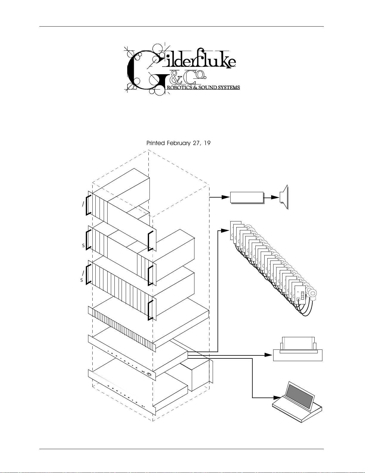
- MACs -
- DIGITAL AUDIO SYSTEM -
Printed February 27, 1999
CC-400
ARD CAGE W/
C
EPEATERS
4 R
CC-400
TWO
ARD CAGES
C
W
/ 8 REPEATERS
CC-1600
ARD CAGE W/
C
EPEATERS
16 R
CC-3250
ARD CAGE W/
C
INI
32 M
EPEATERS
R
MA-100
PA M
ASTER
MA-200
NTERFACE
PA I
AMPLI FIERS SPEAKERS
UP TO 256
PA
STATIONS
REPEATER
P
OWER
S
UPPLIES
AS
NEEDED
OPTIONAL PRINTER
OPTIONAL
C
OMPUTER OR
ERMINAL
T
Page 2

GILDERFLUKE & Co. ¥ 205 SOUTH FLOWER ST. ¥ BURBANK, CALIF. 91502-2102 ¥ 818/840-9484 ¥ FAX 818/840-9485
This page left blank
Page 3

GILDERFLUKE & Co. ¥ 205 SOUTH FLOWER ST. ¥ BURBANK, CALIF. 91502-2102 ¥ 818/840-9484 ¥ FAX 818/840-9485
A System Overview ......................................................................................... 1
Digital Audio Repeaters ............................................................................................................... 1
Approximate Play Times ........................................................................................................... 3
Audio Processing ..................................................................................................................... 5
Intelligent Public Address System .............................................................................................. 5
Digital Audio Repeater/Mixer Cards ............................................................... 10
DR-100 ....................................................................................................................................... 11
DR-300 ....................................................................................................................................... 12
DR-400 ....................................................................................................................................... 13
AB-100 ....................................................................................................................................... 14
Actual Playing Times .............................................................................................................. 15
2 KHz Bandwidth .............................................................................................................. 15
3 KHz Bandwidth .............................................................................................................. 16
4 KHz Bandwidth .............................................................................................................. 16
5 KHz Bandwidth .............................................................................................................. 17
7.5 KHz Bandwidth ........................................................................................................... 17
10 KHz Bandwidth ............................................................................................................ 18
15 KHz Bandwidth ............................................................................................................ 18
Low Level Mixer ...................................................................................................................... 20
Global/Mix Buss ...................................................................................................................... 20
Listening to GLOBAL BUS ................................................................................................... 21
Listening to MIX BUS ......................................................................................................... 22
MIX BUS Feed from Output ............................................................................................... 23
MIX BUS Feed from Pri Mix Point ........................................................................................ 24
GLOBAL BUS Feed From Out ............................................................................................. 25
GLOBAL BUS feed from Pri Mix Point .................................................................................. 26
Voltage Controlled Amplifier (VCA) ........................................................................................ 27
Shelving Equalizer .................................................................................................................. 27
Card Cage and Power Supplies .................................................................... 28
CC-1600 or CC-400 .................................................................................................................. 28
Output .................................................................................................................................. 28
Mix 'A' Input ........................................................................................................................... 28
Mix 'B' Input ........................................................................................................................... 28
Aux. Input .............................................................................................................................. 28
Repeater Start Input .............................................................................................................. 28
Repeater Status Output ......................................................................................................... 28
Voltage Controlled Amplifier (VCA) Input ................................................................................ 28
Digital Data ........................................................................................................................... 29
PA ......................................................................................................................................... 29
VCA Buss ............................................................................................................................... 29
Repeater Hardware Configuration ................................................................. 30
Volume and Other Adjustments ................................................................................................. 30
Main VCA Volume ................................................................................................................. 31
VCA Half Mute Volume .......................................................................................................... 31
Digital Mix Volume ................................................................................................................. 31
External Mix 'A' Volume .......................................................................................................... 31
External MIX 'B' Volume .......................................................................................................... 31
Public Address Volume .......................................................................................................... 31
Buss Feed Volume ................................................................................................................. 31
Treble .................................................................................................................................... 31
Bass ...................................................................................................................................... 31
VCA Buss Dipswitch Configuration ............................................................................................ 32
Global/Mix Buss Dipswitch Configuration ................................................................................. 32
Repeater Start and Status Internal/External Power Jumper ........................................................ 32
Output Driver Select Jumpers .................................................................................................... 33
i
Page 4

GILDERFLUKE & Co. ¥ 205 SOUTH FLOWER ST. ¥ BURBANK, CALIF. 91502-2102 ¥ 818/840-9484 ¥ FAX 818/840-9485
Aux. Port Usage .......................................................................................................................... 33
Configuration from the Serial Port .............................................................................................35
Enter Track Number ............................................................................................................... 36
Baud Rate ............................................................................................................................. 36
Odd Parity Toggle .................................................................................................................. 37
EPROM Type .......................................................................................................................... 37
Inputs Debounce .................................................................................................................. 37
DR-400 Mode ........................................................................................................................ 37
Select From Aux. ................................................................................................................... 37
Direct Select ......................................................................................................................... 38
Mute if Stopped ..................................................................................................................... 38
Start Delay ............................................................................................................................ 38
Early Starts ............................................................................................................................. 39
#1 Priority PA Station ............................................................................................................. 39
#2 Priority PA Station ............................................................................................................. 39
Standard PA Priorities ............................................................................................................. 39
PA Zone Priorities ................................................................................................................... 40
Loop All: ................................................................................................................................40
Group Assignments ............................................................................................................... 40
PA Zone Enables .................................................................................................................... 40
Half-Mute Zone Enables ......................................................................................................... 40
Full-Mute Zone Enables .......................................................................................................... 40
Input Triggering ..................................................................................................................... 41
'A' Input Closing Edge ...................................................................................................... 41
'A' Input Opening Edge .................................................................................................... 41
'B' Input Closing Edge ...................................................................................................... 41
'B' Input Opening Edge .................................................................................................... 41
'PB' Input Closing Edge .................................................................................................... 41
'PB' Input Opening Edge .................................................................................................. 41
'Aux. Port' Input Closing Edge ........................................................................................... 41
'Aux. Port' Input Opening Edge ......................................................................................... 41
eXit Setup Mode .................................................................................................................... 41
Summary of Setup Commands ................................................................................................... 43
Configuration via Dip Switches .................................................................................................. 44
Reset to Default Configuration .............................................................................................. 49
Serial Port Commands ................................................................................. 50
Types of Commands Available ................................................................................................... 52
All ......................................................................................................................................... 52
Track Specific ........................................................................................................................ 52
Group ................................................................................................................................... 52
Cocked ................................................................................................................................. 52
Digital Audio System Serial Commands ..................................................................................... 53
Enter Setup Echo Mode ......................................................................................................... 53
Exit Setup Echo Mode ............................................................................................................ 53
Enter Global Echo Mode ........................................................................................................ 53
Exit Global Echo Mode ........................................................................................................... 53
Enter Echo All Mode .............................................................................................................. 53
Exit Echo All Mode ................................................................................................................. 54
Enter Echo Mode ................................................................................................................... 54
Exit Echo Mode ...................................................................................................................... 54
Track Status Report ................................................................................................................ 54
Special Default Setup ............................................................................................................ 55
LED Port Status ....................................................................................................................... 55
Switch Status ......................................................................................................................... 55
Enter Configuration Mode ..................................................................................................... 55
Memory Address Status .......................................................................................................... 56
ii
Page 5

GILDERFLUKE & Co. ¥ 205 SOUTH FLOWER ST. ¥ BURBANK, CALIF. 91502-2102 ¥ 818/840-9484 ¥ FAX 818/840-9485
Dipswitch #1 Status ............................................................................................................... 56
Dipswitch #2 Status ............................................................................................................... 56
Aux. Port Status ...................................................................................................................... 56
Configuration Dump ............................................................................................................. 56
Load Configuration ............................................................................................................... 59
Start Commands ................................................................................................................... 59
Start Track: ...................................................................................................................... 59
Start All: ........................................................................................................................... 59
Start Cocked: .................................................................................................................. 59
Start Group: .................................................................................................................... 60
Stop Commands: .................................................................................................................. 60
Stop Track ....................................................................................................................... 60
Stop All: ........................................................................................................................... 60
Stop Cocked: .................................................................................................................. 60
Stop Group: .................................................................................................................... 60
Reset Commands: ................................................................................................................ 60
Reset Track: ..................................................................................................................... 60
Reset All: ......................................................................................................................... 60
Reset Cocked: ................................................................................................................ 60
Reset Group: ................................................................................................................... 60
Mute Commands: ................................................................................................................. 60
Mute Track: ..................................................................................................................... 60
Mute All: .......................................................................................................................... 60
Mute Cocked: ................................................................................................................. 60
Mute Group: ................................................................................................................... 60
Half-Mute Commands: .......................................................................................................... 60
Half-Mute Track: ............................................................................................................... 60
Half-Mute All: ................................................................................................................... 60
Half-Mute Cocked: .......................................................................................................... 60
Half-Mute Group: ............................................................................................................. 60
Un-Mute Commands: ............................................................................................................ 61
Un-Mute Track: ................................................................................................................ 61
Un-Mute All: ..................................................................................................................... 61
Un-Mute Cocked: ............................................................................................................ 61
Un-Mute Group: .............................................................................................................. 61
Cock Track: ........................................................................................................................... 61
Un-Cock Track: ...................................................................................................................... 61
Un-Cock All: .......................................................................................................................... 61
Loop Commands: ................................................................................................................. 61
Loop Track: ...................................................................................................................... 61
Loop All: .......................................................................................................................... 61
Loop Cocked: ................................................................................................................. 61
Loop Group: .................................................................................................................... 61
Stop At End Commands: ....................................................................................................... 62
Stop At End Track: ............................................................................................................ 62
Stop At End All: ................................................................................................................ 62
Stop At End Cocked: ....................................................................................................... 62
Stop At End Group: .......................................................................................................... 62
Select Spiel Commands: ....................................................................................................... 62
Select Spiel Track: ............................................................................................................ 62
Select Spiel All: ................................................................................................................ 62
Select Spiel Cocked: ....................................................................................................... 62
Select Spiel Group: .......................................................................................................... 62
Set Delay .............................................................................................................................. 63
Set Memory Address .............................................................................................................. 63
Clock Commands: ................................................................................................................ 63
Stop Clock ...................................................................................................................... 63
iii
Page 6

GILDERFLUKE & Co. ¥ 205 SOUTH FLOWER ST. ¥ BURBANK, CALIF. 91502-2102 ¥ 818/840-9484 ¥ FAX 818/840-9485
Start Clock ...................................................................................................................... 63
Mute Masks ........................................................................................................................... 63
Clear PA Request .................................................................................................................. 64
Summary of Serial Port Commands ........................................................................................... 65
Digital Audio Repeater/Mixer Connections ...................................................... 69
Digital Audio Repeater/Mixer to Motherboard ......................................................................... 69
Single Ended Audio Output .................................................................................................... 69
Single Ended Audio Output .................................................................................................... 69
Digital Audio Repeater/Mixer to Adjustment Card ................................................................... 70
Digital Audio Repeater/Mixer to Memory Expansion Card ........................................................ 70
Aux. Port ................................................................................................................................71
RS-485 Serial Data ................................................................................................................. 71
Power Supply ......................................................................................................................... 71
Start Inputs, Status Output, and Audio Output ........................................................................ 71
Digital Data ........................................................................................................................... 72
Pwr. ....................................................................................................................................... 72
PA ......................................................................................................................................... 73
Mix Buss ................................................................................................................................. 73
Start, Status and VCA Inputs .................................................................................................. 74
VCA Buss ............................................................................................................................... 74
Memory Expansion Boards ........................................................................... 75
Configuration and Installation ................................................................................................... 76
Intelligent Public Address System .................................................................. 77
MA-100 PA Master ..................................................................................................................... 78
MA-200 PA Interface .................................................................................................................. 78
Public Address Stations .............................................................................................................. 78
Digital Audio Sampler .................................................................................. 81
Hardware Requirements ............................................................................................................ 82
Installation ................................................................................................................................. 83
Software and Operation ............................................................................................................. 84
Internal Details .......................................................................................................................... 85
Left Window Display ............................................................................................................... 86
Sample- Required ............................................................................................................ 86
Sample- Actual ................................................................................................................ 86
Start Point ........................................................................................................................ 86
Stop Point ........................................................................................................................ 86
Sample Rate/Filter ........................................................................................................... 86
Stereo/Mono ................................................................................................................... 86
File Name ....................................................................................................................... 86
Sample Name ................................................................................................................. 86
Disk Space ...................................................................................................................... 86
EPROM Count ................................................................................................................. 86
EPROM Type .................................................................................................................... 86
Main Menu Commands ......................................................................................................... 87
Sample Length ................................................................................................................ 87
Playback Times ................................................................................................................ 87
Stereo/Mono ................................................................................................................... 87
Original/Evaluated ........................................................................................................... 87
Looping Mode ................................................................................................................. 87
Threshold (Record) .......................................................................................................... 87
Monitor Mode .................................................................................................................. 89
Sample Rate ................................................................................................................... 89
Filter Cutoff ..................................................................................................................... 89
File Name ....................................................................................................................... 89
iv
Page 7

GILDERFLUKE & Co. ¥ 205 SOUTH FLOWER ST. ¥ BURBANK, CALIF. 91502-2102 ¥ 818/840-9484 ¥ FAX 818/840-9485
Sample Name ................................................................................................................. 90
Record Sample ............................................................................................................... 90
Playback ......................................................................................................................... 90
Configuration Menu ........................................................................................................ 90
Evaluate Data Menu ........................................................................................................ 90
Dump Data ..................................................................................................................... 90
EPROM Image Menu ........................................................................................................ 90
Print Reports .................................................................................................................... 90
Quit ................................................................................................................................ 90
Configuration Menu Commands ........................................................................................... 91
I/O Address ...................................................................................................................... 91
EPROM Size Right ............................................................................................................. 91
EPROM Size Left ............................................................................................................... 91
Rename Sample ............................................................................................................. 91
Delete Sample ................................................................................................................ 91
Erase This File Set ............................................................................................................. 91
Flag Byte Save ................................................................................................................. 91
Evaluation Menu Commands ................................................................................................ 92
Sample Names ................................................................................................................ 92
Playback Times ................................................................................................................ 92
Original/Evaluated ........................................................................................................... 92
Looping Mode ................................................................................................................. 92
Playback ......................................................................................................................... 92
Silence Threshold ............................................................................................................ 92
Trim ................................................................................................................................. 92
Silence Evaluation ........................................................................................................... 92
Data Dump Commands ........................................................................................................ 93
<Up> <Down> .............................................................................................................. 93
<Left> <Right> .............................................................................................................. 93
<PGUP> <PGDN> <W>hole .......................................................................................... 93
<B>itmap ....................................................................................................................... 93
<M>odify ....................................................................................................................... 93
Fade In ........................................................................................................................... 93
Fade Out ........................................................................................................................ 93
Undo ............................................................................................................................... 93
Start ................................................................................................................................ 93
Right/Left ......................................................................................................................... 93
EPROM Image Menu Commands ........................................................................................... 94
EPROM Directory ............................................................................................................. 94
Start EPROM / End EPROM ................................................................................................ 94
Remove EPROM Files ....................................................................................................... 94
Program EPROMs ............................................................................................................. 94
Report Menu Commands ...................................................................................................... 95
Label Name .................................................................................................................... 95
Label Column ................................................................................................................. 95
Start Label ....................................................................................................................... 95
End Label ........................................................................................................................ 95
Channel ......................................................................................................................... 95
Print Test .......................................................................................................................... 95
Print Labels ...................................................................................................................... 95
Name ....................................................................................................................... 95
EPROM ...................................................................................................................... 95
Checksum ................................................................................................................ 95
Time and Date .......................................................................................................... 95
Calibration ................................................................................................................................. 96
A Sample Sample Session .......................................................................................................... 97
v
Page 8

GILDERFLUKE & Co. ¥ 205 SOUTH FLOWER ST. ¥ BURBANK, CALIF. 91502-2102 ¥ 818/840-9484 ¥ FAX 818/840-9485
HEXadecimal to DECIMAL to PERCENTAGE ...................................................... 100
vi
Page 9

GILDERFLUKE & Co. ¥ 205 SOUTH FLOWER ST. ¥ BURBANK, CALIF. 91502-2102 ¥ 818/840-9484 ¥ FAX 818/840-9485
vii
Page 10

GILDERFLUKE & Co. ¥ 205 SOUTH FLOWER ST. ¥ BURBANK, CALIF. 91502-2102 ¥ 818/840-9484 ¥ FAX 818/840-9485
This page left mostly blank
Page 11
GILDERFLUKE & Co. ¥ 205 SOUTH FLOWER ST. ¥ BURBANK, CALIF. 91502-2102 ¥ 818/840-9484 ¥ FAX 818/840-9485
- MACs DIGITAL AUDIO SYSTEM -
- A System Overview -
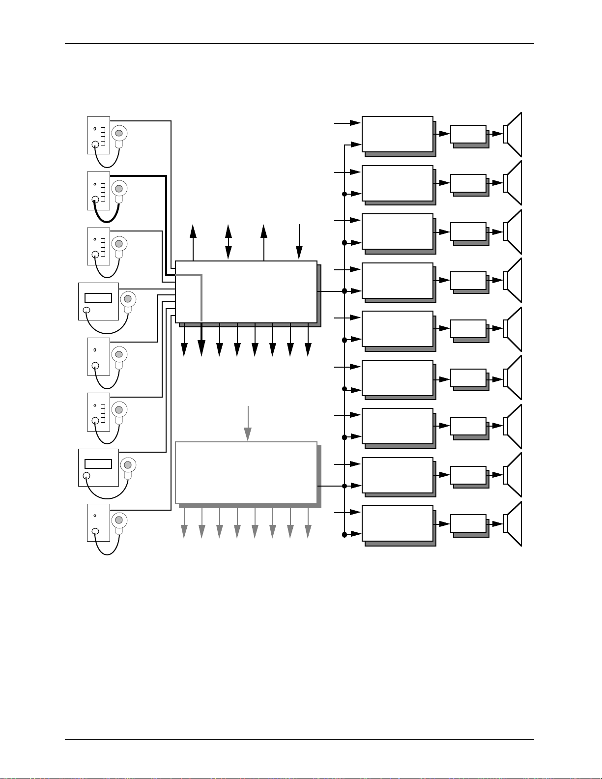
The MACs DIGITAL AUDIO SYSTEM has been developed to meet all of your needs for Digital Audio
Repeaters, Low Level Processing, and Public Address Systems. The following sub systems are available:
¥ Digital Audio Repeaters (DR-100, DR-300, DR-50, and AB-50)
¥ Audio Processing Modules (DR-300 and DR-400)
¥ Intelligent Public Address System
¥ Digital Audio Sampling System (DAS-100)
Each of these can be used alone or as part of your overall audio system. When used together, all
you need to add to make a complete audio system are the power amplifiers and speakers.
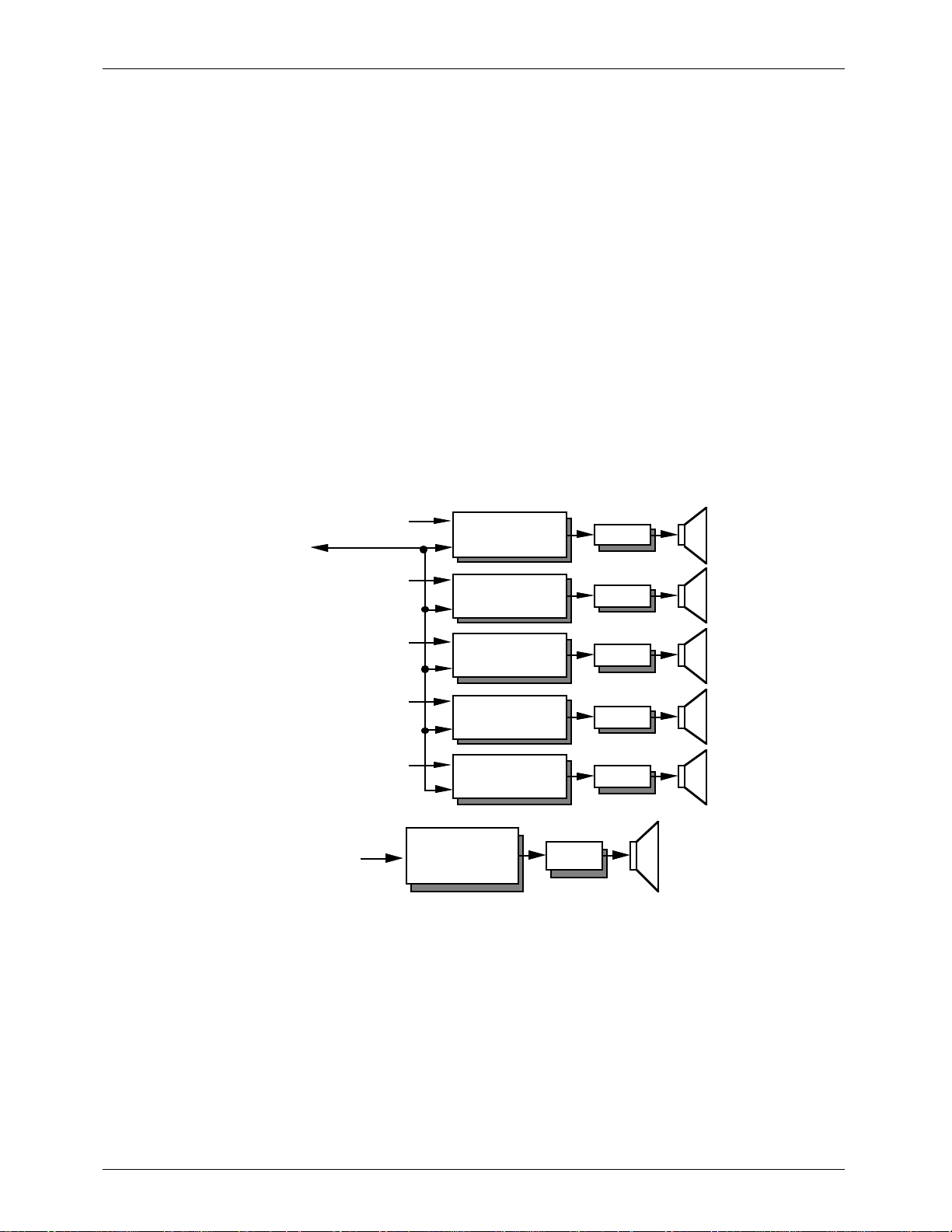
Digital Audio Repeaters:
A Digital Audio Repeater is a solid state replacement for loop and cartridge tape decks. It meets the
demanding requirements for professional voice message, high quality music, and sound effects systems.
Up To 256
DR-100 or DR-300
Cards
Ext. Inputs
Serial
Port
Ext. Inputs
Digital Repeater/
Mixer Card
Digital Repeater/
Mixer Card
Amp
Amp
Ext. Inputs
Ext. Inputs
Ext. Inputs
Ext. Inputs
Digital Repeater/
Mixer Card
Digital Repeater/
Mixer Card
Digital Repeater/
Mixer Card
AB-100 Digital
Audio
Repeater
Amp
Amp
Amp
Amp
Because it is completely solid state, a Digital Audio Repeater never requires any maintenance. A
sound which is recorded on a Digital Audio Repeater will sound just as good twenty or thirty years from
now.
Each DR-100 , AB-100 or DR-300 contains a Digital Audio Repeater (the DR-300 adds a complete
audio processing system to the basic DR-100 card). Their features include:
¥ Each card is a single complete audio playback system (except for power amplification and
speakers).
¥ Message length is virtually unlimited. Up to seven memory expansion cards can be added as
needed.
¥ Bandwidths of up to 15 KHz supported (35.1 KHz sample rate). This is roughly equivalent to a
new audio tape. Each card will also reproduce at 10, 7.5, 5, 4, 3, and 2 KHz bandwidths as
1
Page 12

GILDERFLUKE & Co. ¥ 205 SOUTH FLOWER ST. ¥ BURBANK, CALIF. 91502-2102 ¥ 818/840-9484 ¥ FAX 818/840-9485
well.
¥ Dynamic range of up to 72 dB, again roughly equivalent to a new audio tape.
¥ Up to 255 different messages can be stored on each repeater. Any of these can instantly be
accessed through the RS-485 serial port or switch inputs. This lets you easily build interactive
audio systems.
¥ Dynamic Bandwidth Optimizationª allows the repeater to dynamically follow the highest
frequencies of the source material. It will actually stop using any memory at all if an instant of
silence occurs!
¥ Two opto-isolated switch inputs, as well as a parallel auxiliary port and RS-485 serial port on
each card.
¥ OP-100 optoisolator available for auxiliary port. 1/4 J6 input is compatible with all our
animation systems.
¥ All configuration is done through the serial port with easy to use menus (or with onboard
dipswitches).
¥ One optically isolated status output for remote ÔrunningÕ indicators.
¥ Global/Mix bus allows signals to be mixed into any cardÕs output or a signal to be sent from one
card to any number of other cards. This can be used for sending background tracks or
announcements to any number of cards in an installation, or for combining a number of
outputs from several cards into one.
¥ Volume, Mix/Global bus volume, and Bass and Treble controls on every card. These are on a
small Ôadjuster cardÕ, which can be moved between cards without changing any of the
settings.
¥ DR-100 and DR-300 cards plug into CC-1600 (16 slot) or CC-400 (4 slot) card cages. Rack kits
are available for CC-400 cages.
¥ You can use any number of cards in a system to provide any number of simultaneous audio
tracks.
An AB-100 is a digital audio Repeater which can be used when all you need is a single audio track. It
is a 5 x 12 x 2-1/2 inch box which can be mounted wherever you need to put it. Power for the AB-100
comes from a small wallmount power supply or a 12 VDC power supply for mobile installations.
All configuration and commands for the AB-100 are identical to those for all of the other DR-100
Repeaters. It just wonÕt respond to commands for features for which it doesnÕt have hardware installed
(like the PA system commands).
To record a sound into a Digital Audio Repeater, a master (tape, CD, DAT, video tape) of the sound is
played into a IBM compatible computer which has a DAS-100 Digital Audio Sampler installed. The DAS100 takes the original audio and turns it into digital computer data. This data is then 'burned' into
computer memory chips called EPROMs. These are plugged into the Digital Audio Repeaters. From this
point on, the repeaters can play back this sound whenever they are told to. Since the sound is stored on
the repeater in computer memory chips, it will never change or require any service of any kind. Any
tape deck would require regular cleaning and lubrication of the tape heads and moving parts, as well as
their regular replacement.
Each Digital Audio Repeater can store up to 255 separate messages in its memory. Each of these
can be any length from 1/35th of a second on up. Each of these individual messages is known as a
'spiel'. To access these individual spiels on a card, you can use the serial port interface to the audio
system or the AUX PORT available on each card. Any spiel on any card can be played through or looped
at any time.
Our Digital Audio Repeaters are intelligent, they know how to 'downshift' their bandwidths to follow
the highest frequencies in your audio. If there is a moment of silence in your recording, it will actually
stop using any memory at all until the sound starts up again. Because of this, our systems are able use
far less memory for an equivalent bandwidth. They are also able to play back both low and high
bandwidth sounds from the same Repeater card. The Digital Audio Repeaters each check on how much
2
Page 13
GILDERFLUKE & Co. ¥ 205 SOUTH FLOWER ST. ¥ BURBANK, CALIF. 91502-2102 ¥ 818/840-9484 ¥ FAX 818/840-9485
memory they need to use and adjust their speeds as often as thirty-five times each second.
Although this 'downshifting' saves the amount of memory you need to use, it can make it darned
difficult to estimate the number of EPROMs your recording will need until it has actually been digitized.
The following charts show the capacities with a variety of sounds using different sized EPROMs:
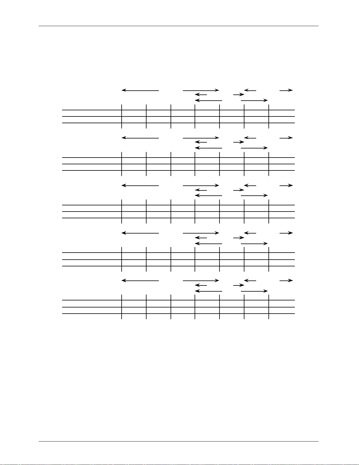
Approximate Play Times:
Estimated Playing Times For Various Types Of Sounds
High Voices
Number Of 27C512
Memory Chips
Each Chip (1 chip) 14 Sec. 9.3 Sec. 7.5 Sec. 5.6 Sec. 3.7 Sec. 2.8 Sec.
each Repeater (16 chips) 3.7 Min. 2.5 Min. 2 Min. 89.5 Sec. 1 Min. 44.6 Sec
each Expansion (32 chips) 5 Min. 4 Min. 3 Min. 2 Min. 89.5 Sec. 1 Min.
Low Rumbles
2 Khz 3 Khz 4 Khz 5 Khz 7.5 Khz 10 Khz 15 Khz
7.5 Min.
Music
High MusicVoices
Sharp Sound Effects
1.7 Sec.
30 Sec.
High Voices
Number Of 27C010
Memory Chips
Each Chip (1 chip) 28 Sec. 18.6 Sec. 14.9 Sec. 11.2 Sec. 7.5 Sec. 5.6 Sec.
each Repeater (16 chips) 7.4 Min. 4.9 Min. 4 Min. 2.75 Min. 2 Min. 1.5 Min.
each Expansion (32 chips) 9.9 Min. 8 Min. 5.5 Min. 4 Min. 3 Min. 2 Min.
Number Of 27C020
Memory Chips
Each Chip (1 chip) 55.9 Sec. 37.3 Sec. 30 Sec. 22.4 Sec. 14.9 Sec. 11.1 Sec.
each Repeater (16 chips) 14.9 Min. 9.9 Min. 8 Min. 6 Min. 4 Min. 3 Min.
each Expansion (32 chips) 19.9 Min. 16 Min. 12 Min. 8 Min. 6 Min. 4 Min.
Number Of 27C040
Memory Chips
Each Chip (1 chip)
each Repeater (16 chips) 29.8 Min. 19.9 Min. 15.9 Min. 11.9 Min. 8 Min. 6 Min.
each Expansion (32 chips) 39.8 Min. 31 Min. 23 Min. 16 Min. 12 Min. 8 Min.
Number Of 27C080
Memory Chips
Each Chip (1 chip)
each Repeater (16 chips) 59.6 Min. 39.8 Min. 32 Min. 24 Min. 16 Min. 12 Min.
each Expansion (32 chips) 79.5 Min. 64 Min. 48 Min. 32 Min. 24 Min. 16 Min.
Low Rumbles
2 Khz 3 Khz 4 Khz 5 Khz 7.5 Khz 10 Khz 15 Khz
14.9 Min.
High Voices
Low Rumbles
2 Khz 3 Khz 4 Khz 5 Khz 7.5 Khz 10 Khz 15 Khz
29.8 Min.
High Voices
Low Rumbles
2 Khz 3 Khz 4 Khz 5 Khz 7.5 Khz 10 Khz 15 Khz
111.8 Sec. 74.6 Sec. 59.7 Sec. 44.7 Sec. 29.8 Sec. 22.3 Sec.
59.6 Min.
High Vo ices
Low Rumbles
2 Khz 3 Khz 4 Khz 5 Khz 7.5 Khz 10 Khz 15 Khz
223.7 Sec.149.1 Sec. 119.3 Sec. 89.5 Sec. 59.7 Min. 44.7 Sec.
119.3 Min.
Music
Music
Music
Music
High MusicVoices
Sharp Sound Effects
3.7 Sec.
1 Min.
High MusicVoices
Sharp Sound Effects
7.5 Sec.
2 Min.
High MusicVoices
Sharp Sound Effects
14.9 Sec.
4 Min.
High MusicVoices
Sharp Sound Effects
29.8 Sec.
8 Min.
Each DR-50 or AB-50 MiniRepeater holds one EPROM. There is no expansion available on these
repeaters.
Each DR-100, DR-300, or AB-100 Digital Audio Repeater Card holds 16 EPROMs. If your recording
needs more space than this, you can add memory expansion cards to the Repeater cards. Each
expansion card holds another 32 EPROMs. The difference between a MX-100 and a MX-200 is their
height. A Digital Audio Repeater / Mixer card with one MX-200 memory expansion board can fit into the
same 1 inch wide space as the Digital Audio Repeater / Mixer alone. With two or more memory
expansion cards, additional 1 inch wide spaces will be needed and you can use MX-100 expansion
cards. Each Digital Audio Repeater / Mixer card can support unlimited amount of data storage. The only
limitation is the physical mounting of the memory expansion cards. Seven expansion cards on a
Repeater card is the normal physical limit for card cage mounted systems. This forms a package which
takes up 4 inches of card cage space.
In audio bricks (AB-100) there is room for up to three memory expansion cards.
The Digital Audio Repeater / Mixer cards can support any type of EPROM memory chips from 27C512
3
Page 14

GILDERFLUKE & Co. ¥ 205 SOUTH FLOWER ST. ¥ BURBANK, CALIF. 91502-2102 ¥ 818/840-9484 ¥ FAX 818/840-9485
up to 27C080. Each Digital Audio Repeater / Mixer must be told what type of memory chips are being
used. This is done in the configuration mode.
4
Page 15

GILDERFLUKE & Co. ¥ 205 SOUTH FLOWER ST. ¥ BURBANK, CALIF. 91502-2102 ¥ 818/840-9484 ¥ FAX 818/840-9485
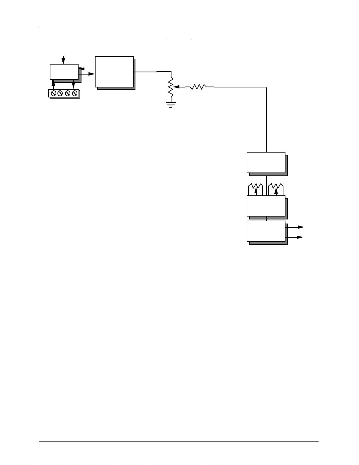
Audio Processing:
DR-300 or DR-400 Repeater cards add:
1) Voltage Controlled Amplifier (VCA)
2) Intelligent PA System support
The VCA can be used to remotely control the volume of the audio produced by the card (or fed to it
from an outside source) with any 0 to 10 VDC control signal, or from the Intelligent PA System
If these cards are used with the Intelligent PA System, they can be configured to respond to full-mute
commands, half-mute commands, or to volume control zone signals from the MA-100 PA System Master.
There are eight full and half-mute zones available. Any individual card can be told to respond to any
number of these zone commands. There are also eight volume control zones available. Any individual
card can be told to respond to any one of the eight volume control zones or to the external VCA input
available on each card.
The DR-400 is used when you need to send an audio signal from an external source through Voltage
Controlled Amplifiers (VCAs), Intelligent Public Address System, and Shelving Equalizers.
Intelligent Public Address System:
The Intelligent Public Address System is used where a powerful and flexible zoned Public Address
System is needed. It can be used with our DR-300 and DR-400 Digital Audio Repeater cards or in stand
alone installations.
The PA system consists of one PA Master, one PA Interface Panel for each eight PA stations (the first
one is part of the PA Master), and the PA Stations themselves. These are available in four different styles:
1) One Button PA Stations use the microphoneÕs Push To Talk (PTT) button to select any one of the
PA zones.
2) The Four Button PA stations can select any of four different PA zones, plus one more with the
microphoneÕs PTT button. You can tell the buttons on these stations to latch the zone
requested, only momentarily select the zone, or latch it until the next time the PTT button is
released.
3) The Smart PA stations can be set up to access all of the features in the entire audio system,
including any Digital Audio Repeaters, Animation Control Systems, and volume control zones
which happen to be attached to it. They are available with backlit LCD displays on them. Their
pushbuttons are normally located on the microphone itself.
4) Phantom PA Stations are used to tie a Digital Audio Repeater to the PA system in order to make
automated announcements. When the Repeater is triggered, it will select a PA zone and feed
the audio output from the repeater to the selected zone.
Each PA Interface Panel has connections for eight PA stations, eight balanced ÔlocalÕ PA outputs, and
one (optionally eight) balanced Back Ground Music (BGM) inputs. The BGM is normally fed to the eight
local PA outputs. When one of these responds to a PA zone request, the PA announcement is fed to it as
the BGM is half-muted. Each local PA output can respond to four different prioritized PA zone requests.
The Intelligent Public Address System features include:
¥ Up to 511 PA zones are available. Sixteen cross-zone announcements can be made at one
time, along with any number of local PA zone requests. These latter take place when any PA
station requests itÕs local PA output.
¥ Supports up to 256 PA stations. These are available in One Button, Four Button or Smart
models.
¥ All setup is done through easy to use menus using any PC or terminal. Configuration includes
selecting which zones any PA station button will select, and the normal, half-muted, and PA
announcement volumes for the local PA outputs. A key lock and battery protects the
configuration data from unauthorized access and power failure.
5
Page 16

GILDERFLUKE & Co. ¥ 205 SOUTH FLOWER ST. ¥ BURBANK, CALIF. 91502-2102 ¥ 818/840-9484 ¥ FAX 818/840-9485
¥ Separate printer and terminal outputs can give a running record of all PA system activity.
¥ PA Master controls up to eight volume zones, or any other 0 to 10 VDC controlled device
(lights, screens, etc.).
¥ Eight PA stations per Interface Panel. Stations are transformer and opto isolated from the rest of
the system.
¥ Wiring to all PA stations is by 8 conductor telephone line. Power for the stations is provided by
the PA interface.
¥ Each DR-300 or DR-400 Repeater added to the Intelligent PA system adds another possible PA
output to it.
¥ The PA system can act as a bridge to run animation systems, Digital Audio Repeaters, etc.
from PA stations.
6
Page 17
GILDERFLUKE & Co. ¥ 205 SOUTH FLOWER ST. ¥ BURBANK, CALIF. 91502-2102 ¥ 818/840-9484 ¥ FAX 818/840-9485
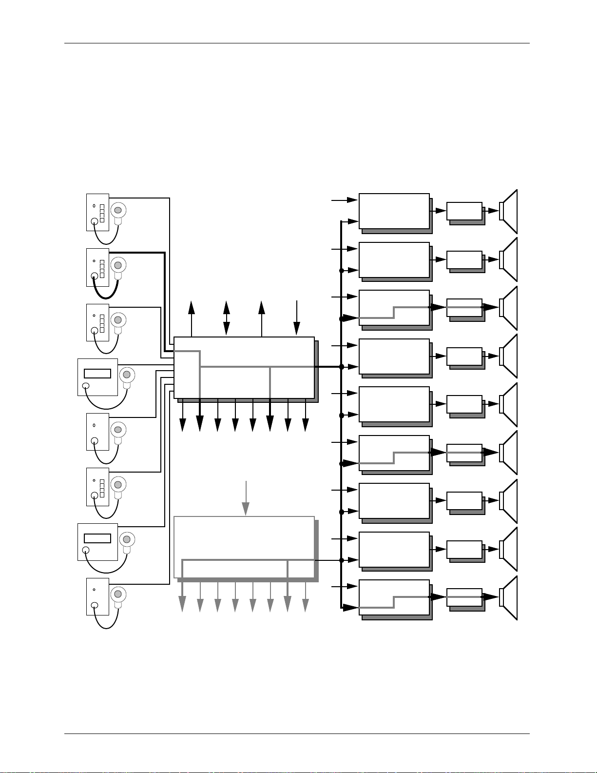
To support the PUBLIC ADDRESS option you will need:
¥ One MA-100 PA MASTER to control the system and the first eight PA STATIONS.
¥ One MA-200 for each additional eight PA STATIONS (beyond the first eight) or Local PA Outputs
needed.
¥ Any combination of up to 256 SMART or DUMB PA STATIONS.
¥ Optionally, any combination of DR-300 or DR-400 Digital Audio Repeater / Mixer cards.
UP TO 256
UP TO 256
PA/INTERCOM
STATIONS
EXT. INPUTS
EXT. INPUTSEXT. INPUTS
DIGITAL
REPEATER/
MIXER CARDS
Digital
Repeater/
Mixer Card
Digital
Repeater/
Mixer Card
AMP
AMP
Printer Port
Serial Port
Analog Output
MA-100
PA Master
Local PA Outputs (8)
BGM input (1 or 8)
up to 31
MA-200
PA Interface Cards
BGM input (1 or 8)
Repeater/
Mixer Card
EXT. INPUTSEXT. INPUTS
EXT. INPUTSEXT. INPUTS
EXT. INPUTSEXT. INPUTS
Repeater/
Mixer Card
Repeater/
Mixer Card
Repeater/
Mixer Card
Repeater/
Mixer Card
Repeater/
Mixer Card
Digital
AMP
Digital
AMP
Digital
AMP
Digital
AMP
Digital
AMP
Digital
AMP
Digital
Repeater/
Mixer Card
AMP
Local PA Outputs (8)
As shown by the darkened audio path in the above illustration, when a user at any PA station
requests a PA ZONE, an audio path is opened to any of the Local PA Outputs and DIGITAL REPEATER /
MIXER cards in the system which have been configured to respond to requests for that PA ZONE (in this
example there are three DR-300 or DR-400 cards and four Local PA Outputs responding). The normal
audio on those outputs is dropped to the half muted level (this level is adjustable on each output) while
the audio from the PA station is routed to the outputs (the volume of the announcement is also
adjustable on each output). The rest of the audio system and the Repeaters on the affected DR-300
7
Page 18
GILDERFLUKE & Co. ¥ 205 SOUTH FLOWER ST. ¥ BURBANK, CALIF. 91502-2102 ¥ 818/840-9484 ¥ FAX 818/840-9485
cards continue to operate as usual. Up to sixteen such PA announcements can go on at the same time
UP TO 256
UP TO 256
PA/INTERCOM
STATIONS
EXT. INPUTS
EXT. INPUTSEXT. INPUTS
DIGITAL
REPEATER/
MIXER CARDS
Digital
Repeater/
Mixer Card
Digital
Repeater/
Mixer Card
AMP
AMP
Printer Port
Serial Port
Analog Output
MA-100
PA Master
Local PA Outputs (8)
BGM input (1 or 8)
up to 31
MA-200
PA Interface Cards
BGM input (1 or 8)
Repeater/
Mixer Card
EXT. INPUTSEXT. INPUTS
EXT. INPUTSEXT. INPUTS
EXT. INPUTSEXT. INPUTS
Repeater/
Mixer Card
Repeater/
Mixer Card
Repeater/
Mixer Card
Repeater/
Mixer Card
Repeater/
Mixer Card
Digital
AMP
Digital
AMP
Digital
AMP
Digital
AMP
Digital
AMP
Digital
AMP
Digital
Repeater/
Mixer Card
AMP
Local PA Outputs (8)
Eight LOCAL PA OUTPUTS are available from each MA-100 or MA-200 card. Each of these outputs normally carries whatever audio is being fed into the ÔBack Ground Music (BGM) inputÕ on the back of the
unit. When a request for a PA zone comes in from any of the PA STATIONS, the BGM level on any of the
LOCAL PA OUTPUTS is dropped to a half-muted level on those LOCAL PA OUTPUTS which are responding
and the PA audio is mixed into the output. All audio levels and settings for the LOCAL PA OUTPUTS are
adjusted through the software on the MA-100 PA Master. Each LOCAL PA OUTPUT can be told to respond
to up to four different PA zone requests. If the PA STATION requesting the LOCAL PA OUTPUT has the same
ÔnumberÕ as the output being requested, a special ÔLOCAL PA MODE can be used as shown above. This
bypasses the 16 trunk lines which normally carry the PA audio feeds to allow up to 256 such PA
announcements to go on at the same time.
There are 256 possible PA ZONES. Any Digital Audio Repeater / Mixer card can be configured to
respond to up to eight different PA ZONE requests. Any number of cards can be configured to respond
to any individual PA ZONE request. This allows a PA ZONE to be assigned as a global PA ZONE by simply
8
Page 19

GILDERFLUKE & Co. ¥ 205 SOUTH FLOWER ST. ¥ BURBANK, CALIF. 91502-2102 ¥ 818/840-9484 ¥ FAX 818/840-9485
telling all the Repeater cards in the system to respond to it.
DUMB PA STATIONS are available with either four buttons (plus the microphone button) or one button
(just the microphone button). Any of the buttons can be configured to access any PA zone in the
system. The buttons on the front of the four button stations can be configured as push-to-talk buttons, to
latch the last requested zone, or auto-release the last zone latched when the microphone button is
released.
Because the PA system can be used for safety announcements, a number of different priority
options are available. The Digital Audio Repeater / Mixer cards each have one PA station each assigned
as top and second priority. These are assigned individually for each Digital Audio Repeater / Mixer card.
Valid PA requests from the second priority PA station override all other PA requests except those from the
top PA station. These priority PA STATIONS will usually be assigned to the station from which safety
announcements are normally made, and to the PA station located closest to the emergency exit for the
area covered by the speakers attached to that particular Digital Audio Repeater / Mixer card.
If no other PA priority options are used, then all other PA requests will be treated equally. If two valid
PA requests come in to the same Repeater card, then both are honored and the audio from both are
mixed equally. The STANDARD PRIORITY OPTION allows you to give PA STATIONS with higher number assignments priority over those with lower numbers. The ZONE PRIORITY OPTION allows PA ZONE requests for
higher numbered PA ZONES to take priority over those for lower numbered PA ZONES.
The local PA Outputs' priorities are set by the order in which you enter the PA zones an output will
respond to. The first entry has the highest priority.
For automated PA announcements, a phantom PA station is used. It is like any other PA STATION
except that it has no buttons or microphone on it. The audio and status output from a Digital Audio
Repeater is attached to the phantom PA station. When the Repeater is started, the status output triggers
the phantom PA station to request a PA ZONE and then feeds its audio into it. The audio will then be
routed to the appropriate audio outputs through the PA system just like any other announcement.
Different spiels can also be requested and PA Zones accessed through the serial port if needed.
SMART PA STATIONS are available with up to 18 buttons on their microphones. Any button can be
configured to request any other intercom station, mute or half-mute zone, send commands to one or
more Digital Audio Repeaters, or ramp the volume of any volume control zone up or down. For those PA
STATIONS which need access to more features than this number of buttons would allow, a numeric-style
entry is used to give them access to any features which you have enabled.
9
Page 20
GILDERFLUKE & Co. ¥ 205 SOUTH FLOWER ST. ¥ BURBANK, CALIF. 91502-2102 ¥ 818/840-9484 ¥ FAX 818/840-9485
Digital Audio Repeater/Mixer Cards:
These cards are the heart of the MACs Digital Audio System. Each card contains virtually all of the
circuitry needed to reproduce and process one audio track. Up to 16 of these cards can fit into one
CC-1600 card cage. The Digital Audio Repeater / Mixer cards are available in four versions to best suit
your needs:
DR-100: Digital Audio Repeater and Shelving Equalizer only.
DR-300: Full card containing Digital Audio Repeater, Mixer, Voltage Controlled Amplifier,
Public Address / Muting System, and Shelving Equalizer.
DR-400: Public Address/Muting System, Mixer, Voltage Controlled Amplifier, and Shelving
Equalizer.
AB-100: Stand-alone version of the DR-100 Repeater card. Comes complete with power
supply and case.
A basic DIGITAL AUDIO SYSTEM consists of:
¥ One Digital Audio Repeater / Mixer card for each audio track (DR-100)
¥ Card Cages to hold the Digital Audio Repeater / Mixer cards
¥ Power supplies
¥ Power amplifiers
¥ Speakers
UP TO 256
DIGITAL REPEATER/
MIXER CARDS
EXT. INPUTS
SERIAL
PORT
EXT. INPUTS
DIGITAL
REPEATER/
MIXER CARD
DIGITAL
REPEATER/
MIXER CARD
AMP
AMP
EXT. INPUTS
EXT. INPUTS
EXT. INPUTS
DIGITAL
REPEATER/
MIXER CARD
DIGITAL
REPEATER/
MIXER CARD
DIGITAL
REPEATER/
MIXER CARD
AMP
AMP
AMP
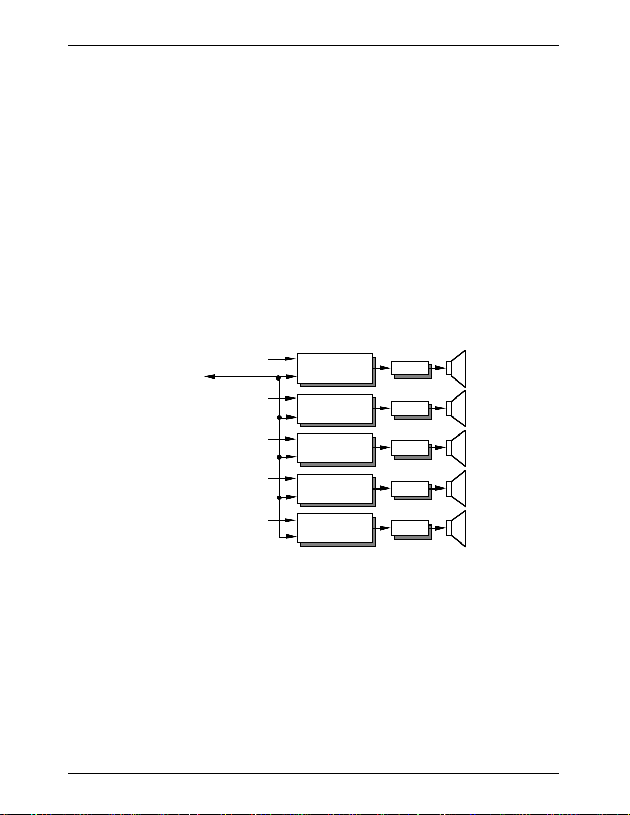
In the basic system DIGITAL REPEATER / MIXER cards act as the source for the audio material and/or to
process audio signals before sending them to the power amplifiers and speakers. Up to 256 audio tracks
can be supported by using up to 256 Digital Audio Repeater / Mixer cards. The DIGITAL REPEATER is
normally the primary source of audio for each track on DR-100 or DR-300 cards. Secondary audio
sources can be fed into one of the two external mix inputs available on each DR-300 and DR-400 card.
These can come from external sources like audio tape, CD's, video, film, or live microphones.
Additional mixing between individual cards can be done using the MIX / GLOBAL bus available on all
DR- Repeaters. The MIX BUS can be used to send a signal which is the combination (sum) of any number
of audio signals from other cards into any other one card. This can be used where you need a mixed
output, or for bi-amp or sub-woofer applications. The GLOBAL BUS can be used to send the output from
any one card to be mixed into the outputs of any number of other cards. This can be used if you need
to send a background sound or music to a number of different audio tracks.
The Digital Audio Repeaters can be configured to whatever you want. They can play any spiel just
once, or loop any spiel continuously. A delay can be inserted before each spiel, or between each
iteration when looping. The control signals for the Repeaters can be sent to them through the serial port,
or through the two opto-isolated inputs and auxiliary port available on each card. The external inputs
10
Page 21

GILDERFLUKE & Co. ¥ 205 SOUTH FLOWER ST. ¥ BURBANK, CALIF. 91502-2102 ¥ 818/840-9484 ¥ FAX 818/840-9485
can run from the audio system's own isolated 'dirty' power supply, or from an external power supply.
Up to 255 different spiels can be stored on each Digital Audio Repeater. These can be any length
from 1/35th of a second on up. They can be accessed at random through the serial port or through the
AUX PORT. The AUX PORT can be told to use a 'one of eight' style selection, or a parallel 8 bit binary
input.
If DR-300 or DR-400 cards are used in a basic audio system, you can use their Voltage Controlled
Amplifiers (VCAs) to change the volume of the output from each card. Each card has its own 0 to 10
volt input for the VCA, or you can attach the VCA to one of eight VCA BUS lines if you need to control
the volume of more than one card at a time.
The following illustrates the four Digital Audio Repeater / Mixer card options. (The GLOBAL / MIX BUS
structure of each card is shown in the GLOBAL LISTEN mode.)
DR-100
ISOLATED
POWER SUPPLY
OPTO
ISOLATION
START & STATUS
GLOBAL/MIX BUS #1
GLOBAL/MIX BUS #2
GLOBAL/MIX BUS #3
GLOBAL/MIX BUS #4
AUXILIARY INPUT
DIGITAL
AUDIO
REPEATER
35 KHz
LOWPASS
BASS TREB.
SHELVING
EQUALIZER
OUTPUT
DRIVERS
(or Optional
High or Low
Pass Filters)
OUT
11
Page 22
GILDERFLUKE & Co. ¥ 205 SOUTH FLOWER ST. ¥ BURBANK, CALIF. 91502-2102 ¥ 818/840-9484 ¥ FAX 818/840-9485
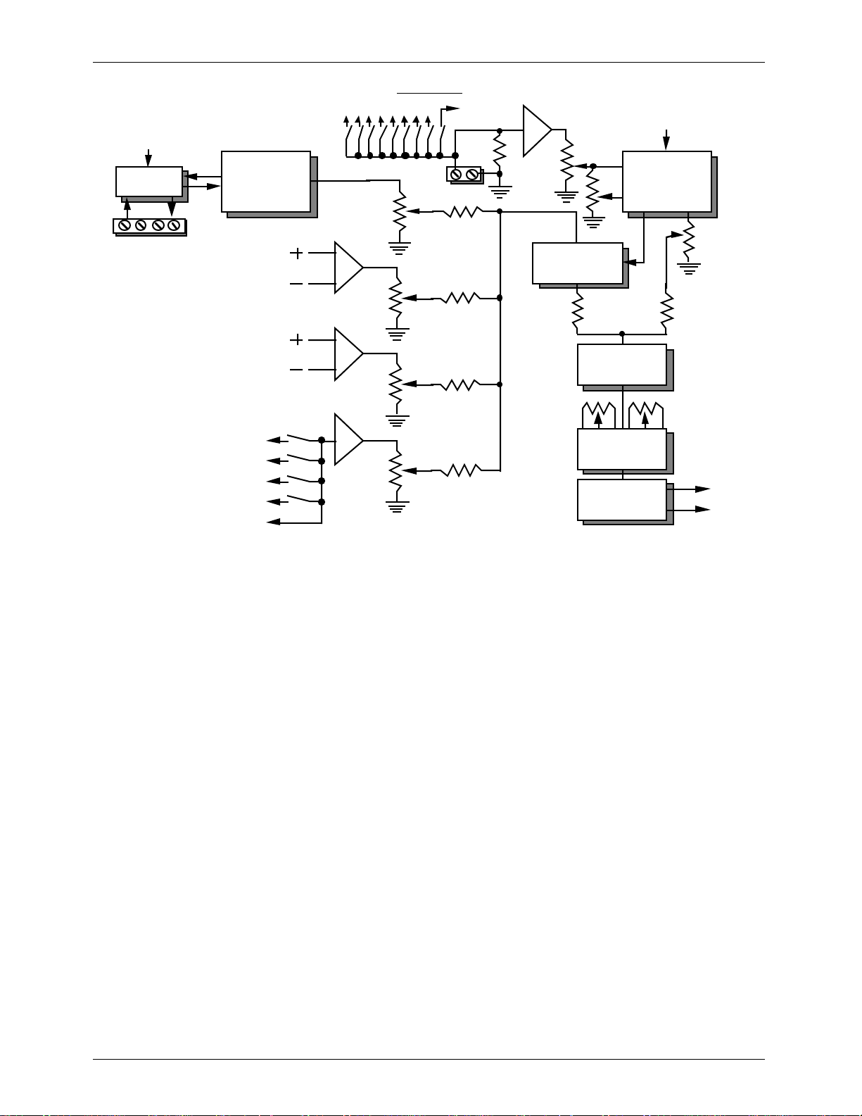
DR-300
PA AUDIO & CONTROL SIGNALS
FROM MA-100 MASTER
1/2
MUTE
PUBLIC
ADDRESS
SYSTEM
VOLTAGE
CONTROLED
AMPLIFIER
PA
VOLUME
ISOLATED
POWER SUPPLY
OPTO
ISOLATION
START & STATUS
DIGITAL
AUDIO
REPEATER
EXTERNAL MIX INPUT 'A'
VCA BUS
VCA IN/OUT
10v REF.
VOLUME
EXTERNAL MIX INPUT 'B'
GLOBAL/MIX BUS #1
GLOBAL/MIX BUS #2
GLOBAL/MIX BUS #3
GLOBAL/MIX BUS #4
35Khz
LOWPASS
FILTER
BASS TREB.
SHELVING
EQUALIZER
OUTPUT
DRIVERS
(or Optional
High or Low
Pass Filters)
OUT
12
Page 23
'
'
GILDERFLUKE & Co. ¥ 205 SOUTH FLOWER ST. ¥ BURBANK, CALIF. 91502-2102 ¥ 818/840-9484 ¥ FAX 818/840-9485
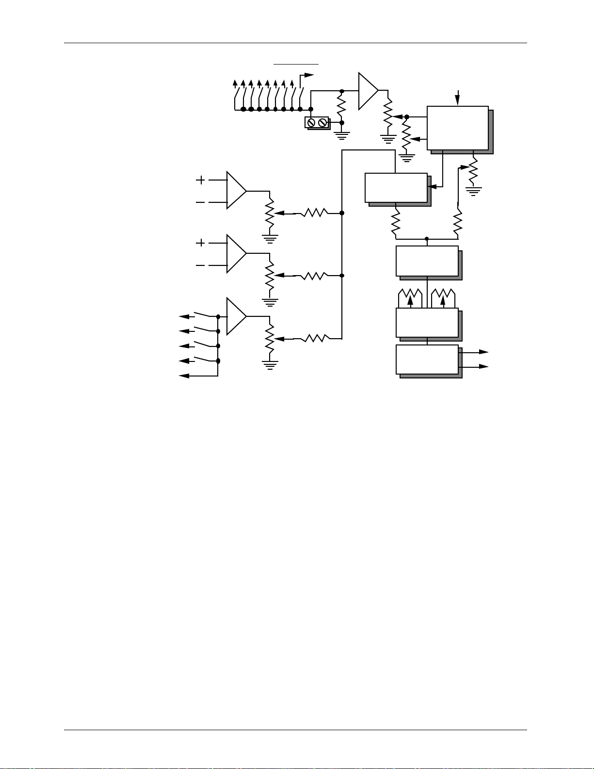
DR-400
PA AUDIO & CONTROL SIGNALS
FROM MA-100 MASTER
1/2
MUTE
PUBLIC
ADDRESS
SYSTEM
VOLTAGE
CONTROLED
AMPLIFIER
PA
VOLUME
EXTERNAL MIX INPUT 'A
VCA BUS
VCA IN/OUT
10v REF.
VOLUME
EXTERNAL MIX INPUT 'B
GLOBAL/MIX BUS #1
GLOBAL/MIX BUS #2
GLOBAL/MIX BUS #3
GLOBAL/MIX BUS #4
AUXILIARY INPUT
35Khz
LOWPASS
FILTER
BASS TREB.
SHELVING
EQUALIZER
OUTPUT
DRIVERS
(or Optional
High or Low
Pass Filters)
OUT
13
Page 24
GILDERFLUKE & Co. ¥ 205 SOUTH FLOWER ST. ¥ BURBANK, CALIF. 91502-2102 ¥ 818/840-9484 ¥ FAX 818/840-9485
AB-100
ISOLATED
POWER SUPPLY
OPTO
ISOLATION
START & STATUS
DIGITAL
AUDIO
REPEATER
35 KHz
LOWPASS
BASS TREB.
SHELVING
EQUALIZER
OUTPUT
DRIVERS
(or Optional
High or Low
Pass Filters)
OUT
14
Page 25

GILDERFLUKE & Co. ¥ 205 SOUTH FLOWER ST. ¥ BURBANK, CALIF. 91502-2102 ¥ 818/840-9484 ¥ FAX 818/840-9485
Actual Playing Times:
The following tables show in seconds the capacities of several different types of EPROMs at several
different fixed bandwidths. All values shown are in seconds.
- 2 KHz Bandwidth (4,687 Hz UPDATE RATE) -
EPROM: 27C512 27C010 27C020 27C040 27C080
SIZE: 64K x 8 128K x 8 256K x 8 512K x 8 1M x 8
Number of bytes per EPROM: 65,536 131,072 262,144 524,288 1,048,576
1 EPROM (1 DR-50 MiniRepeater) 13.98 27.96 55.92 111.85 223.70
2 EPROMs 27.96 55.92 111.85 223.70 447.39
3 EPROMs 41.94 83.89 167.77 335.54 671.09
4 EPROMs 55.92 111.85 223.70 447.39 894.78
5 EPROMs 69.91 139.81 279.62 559.24 1,118.48
6 EPROMs 83.89 167.77 335.54 671.09 1,342.18
7 EPROMs 97.87 195.73 391.47 782.94 1,565.87
8 EPROMs 111.85 223.70 447.39 894.78 1,789.57
9 EPROMs 125.83 251.66 503.32 1,006.63 2,013.27
10 EPROMs 139.81 279.62 559.24 1,118.48 2,236.96
11 EPROMs 153.79 307.58 615.16 1,230.33 2,460.66
12 EPROMs 167.77 335.54 671.09 1,342.18 2,684.35
13 EPROMs 181.75 363.51 727.01 1,454.03 2,908.05
14 EPROMs 195.73 391.47 782.94 1,565.87 3,131.75
15 EPROMs 209.72 419.43 838.86 1,677.72 3,355.44
16 EPROMs 223.70 447.39 894.78 1,789.57 3,579.14
Each Expansion: 32 EPROMs 447.39 894.78 1,789.57 3,579.14 7,158.28
Repeater + 1 Expansion: 48 EPROMs 671.09 1,342.18 2,684.35 5,368.71 10,737.42
Repeater + 2 Expansions: 80 EPROMs 1,118.48 2,236.96 4,473.92 8,947.85 17,895.70
Repeater + 3 Expansions: 112 EPROMs 1,565.87 3,131.75 6,263.49 12,526.99 25,053.98
Repeater + 4 Expansions: 144 EPROMs 2,013.27 4,026.53 8,053.06 16,106.13 32,212.25
Repeater + 5 Expansions: 176 EPROMs 2,460.66 4,921.32 9,842.63 19,685.27 39,370.53
Repeater + 6 Expansions: 208 EPROMs 2,908.05 5,816.10 11,632.20 23,264.41 46,528.81
Repeater + 7 Expansions: 240 EPROMs 3,355.44 6,710.89 13,421.77 26,843.55 53,687.09
15
Page 26

GILDERFLUKE & Co. ¥ 205 SOUTH FLOWER ST. ¥ BURBANK, CALIF. 91502-2102 ¥ 818/840-9484 ¥ FAX 818/840-9485
- 3 KHz Bandwidth (7,031 Hz UPDATE RATE) -
EPROM: 27C512 27C010 27C020 27C040 27C080
SIZE: 64K x 8 128K x 8 256K x 8 512K x 8 1M x 8
Number of bytes per EPROM: 65,536 131,072 262,144 524,288 1,048,576
1 EPROM (1 DR-50 MiniRepeater) 9.32 18.64 37.28 74.57 149.13
2 EPROMs 18.64 37.28 74.57 149.13 298.26
3 EPROMs 27.96 55.92 111.85 223.70 447.39
4 EPROMs 37.28 74.57 149.13 298.26 596.52
5 EPROMs 46.60 93.21 186.41 372.83 745.65
6 EPROMs 55.92 111.85 223.70 447.39 894.78
7 EPROMs 65.24 130.49 260.98 521.96 1,043.92
8 EPROMs 74.57 149.13 298.26 596.52 1,193.05
9 EPROMs 83.89 167.77 335.54 671.09 1,342.18
10 EPROMs 93.21 186.41 372.83 745.65 1,491.31
11 EPROMs 102.53 205.05 410.11 820.22 1,640.44
12 EPROMs 111.85 223.70 447.39 894.78 1,789.57
13 EPROMs 121.17 242.34 484.68 969.35 1,938.70
14 EPROMs 130.49 260.98 521.96 1,043.92 2,087.83
15 EPROMs 139.81 279.62 559.24 1,118.48 2,236.96
16 EPROMs 149.13 298.26 596.52 1,193.05 2,386.09
Each Expansion: 32 EPROMs 298.26 596.52 1,193.05 2,386.09 4,772.1
Repeater + 1 Expansion: 48 EPROMs 447.39 894.78 1,789.57 3,579.14 7,158.28
Repeater + 2 Expansions: 80 EPROMs 745.65 1,491.31 2,982.62 5,965.23 11,930.46
Repeater + 3 Expansions: 112 EPROMs 1,043.92 2,087.83 4,175.66 8,351.33 16,702.65
Repeater + 4 Expansions: 144 EPROMs 1,342.18 2,684.35 5,368.71 10,737.42 21,474.84
Repeater + 5 Expansions: 176 EPROMs 1,640.44 3,280.88 6,561.76 13,123.51 26,247.02
Repeater + 6 Expansions: 208 EPROMs 1,938.70 3,877.40 7,754.80 15,509.60 31,019.21
Repeater + 7 Expansions: 240 EPROMs 2,236.96 4,473.92 8,947.85 17,895.70 35,791.39
- 4 KHz Bandwidth (8,789 Hz UPDATE RATE) -
EPROM: 27C512 27C010 27C020 27C040 27C080
SIZE: 64K x 8 128K x 8 256K x 8 512K x 8 1M x 8
Number of bytes per EPROM: 65,536 131,072 262,144 524,288 1,048,576
1 EPROM (1 DR-50 MiniRepeater) 7.46 14.91 29.83 59.65 119.30
2 EPROMs 14.91 29.83 59.65 119.30 238.61
3 EPROMs 22.37 44.74 89.48 178.96 357.91
4 EPROMs 29.83 59.65 119.30 238.61 477.22
5 EPROMs 37.28 74.57 149.13 298.26 596.52
6 EPROMs 44.74 89.48 178.96 357.91 715.83
7 EPROMs 52.20 104.39 208.78 417.57 835.13
8 EPROMs 59.65 119.30 238.61 477.22 954.44
9 EPROMs 67.11 134.22 268.44 536.87 1,073.74
10 EPROMs 74.57 149.13 298.26 596.52 1,193.05
11 EPROMs 82.02 164.04 328.09 656.18 1,312.35
12 EPROMs 89.48 178.96 357.91 715.83 1,431.66
13 EPROMs 96.94 193.87 387.74 775.48 1,550.96
14 EPROMs 104.39 208.78 417.57 835.13 1,670.27
15 EPROMs 111.85 223.70 447.39 894.78 1,789.57
16 EPROMs 119.30 238.61 477.22 954.44 1,908.87
Each Expansion: 32 EPROMs 238.61 477.22 954.44 1,908.87 3,817.75
Repeater + 1 Expansion: 48 EPROMs 357.91 715.83 1,431.66 2,863.31 5,726.62
Repeater + 2 Expansions: 80 EPROMs 596.52 1,193.05 2,386.09 4,772.19 9,544.37
Repeater + 3 Expansions: 112 EPROMs 835.13 1,670.27 3,340.53 6,681.06 13,362.12
Repeater + 4 Expansions: 144 EPROMs 1,073.74 2,147.48 4,294.97 8,589.93 17,179.87
Repeater + 5 Expansions: 176 EPROMs 1,312.35 2,624.70 5,249.40 10,498.81 20,997.62
Repeater + 6 Expansions: 208 EPROMs 1,550.96 3,101.92 6,203.84 12,407.68 24,815.37
Repeater + 7 Expansions: 240 EPROMs 1,789.57 3,579.14 7,158.28 14,316.56 28,633.12
16
Page 27

GILDERFLUKE & Co. ¥ 205 SOUTH FLOWER ST. ¥ BURBANK, CALIF. 91502-2102 ¥ 818/840-9484 ¥ FAX 818/840-9485
- 5 KHz Bandwidth (11,718 Hz UPDATE RATE) -
EPROM: 27C512 27C010 27C020 27C040 27C080
SIZE: 64K x 8 128K x 8 256K x 8 512K x 8 1M x 8
Number of bytes per EPROM: 65,536 131,072 262,144 524,28 1,048,576
1 EPROM (1 DR-50 MiniRepeater) 5.59 11.18 22.37 44.74 89.48
2 EPROMs 11.18 22.37 44.74 89.48 178.96
3 EPROMs 16.78 33.55 67.11 134.22 268.44
4 EPROMs 22.37 44.74 89.48 178.96 357.91
5 EPROMs 27.96 55.92 111.85 223.70 447.39
6 EPROMs 33.55 67.11 134.22 268.44 536.87
7 EPROMs 39.15 78.29 156.59 313.17 626.35
8 EPROMs 44.74 89.48 178.96 357.91 715.83
9 EPROMs 50.33 100.66 201.33 402.65 805.31
10 EPROMs 55.92 111.85 223.70 447.39 894.78
11 EPROMs 61.52 123.03 246.07 492.13 984.26
12 EPROMs 67.11 134.22 268.44 536.87 1,073.74
13 EPROMs 72.70 145.40 290.81 581.61 1,163.22
14 EPROMs 78.29 156.59 313.17 626.35 1,252.70
15 EPROMs 83.89 167.77 335.54 671.09 1,342.18
16 EPROMs 89.48 178.96 357.91 715.83 1,431.66
Each Expansion: 32 EPROMs 178.96 357.91 715.83 1,431.66 2,863.31
Repeater + 1 Expansion: 48 EPROMs 268.44 536.87 1,073.74 2,147.48 4,294.97
Repeater + 2 Expansions: 80 EPROMs 447.39 894.78 1,789.57 3,579.14 7,158.28
Repeater + 3 Expansions: 112 EPROMs 626.35 1,252.70 2,505.40 5,010.80 10,021.59
Repeater + 4 Expansions: 144 EPROMs 805.31 1,610.61 3,221.23 6,442.45 12,884.90
Repeater + 5 Expansions: 176 EPROMs 984.26 1,968.53 3,937.05 7,874.11 15,748.21
Repeater + 6 Expansions: 208 EPROMs 1,163.22 2,326.44 4,652.88 9,305.76 18,611.52
Repeater + 7 Expansions: 240 EPROMs 1,342.18 2,684.35 5,368.71 10,737.42 21,474.84
- 7.5 KHz Bandwidth (17,578 Hz UPDATE RATE) -
EPROM: 27C512 27C010 27C020 27C040 27C080
SIZE: 64K x 8 128K x 8 256K x 8 512K x 8 1M x 8
Number of bytes per EPROM: 65,536 131,072 262,144 524,288 1,048,576
1 EPROM (1 DR-50 MiniRepeater) 3.73 7.46 14.91 29.83 59.65
2 EPROMs 7.46 14.91 29.83 59.65 119.30
3 EPROMs 11.18 22.37 44.74 89.48 178.96
4 EPROMs 14.91 29.83 59.65 119.30 238.61
5 EPROMs 18.64 37.28 74.57 149.13 298.26
6 EPROMs 22.37 44.74 89.48 178.96 357.91
7 EPROMs 26.10 52.20 104.39 208.78 417.57
8 EPROMs 29.83 59.65 119.30 238.61 477.22
9 EPROMs 33.55 67.11 134.22 268.44 536.87
10 EPROMs 37.28 74.57 149.13 298.26 596.52
11 EPROMs 41.01 82.02 164.04 328.09 656.18
12 EPROMs 44.74 89.48 178.96 357.91 715.83
13 EPROMs 48.47 96.94 193.87 387.74 775.48
14 EPROMs 52.20 104.39 208.78 417.57 835.13
15 EPROMs 55.92 111.85 223.70 447.39 894.78
16 EPROMs 59.65 119.30 238.61 477.22 954.44
Each Expansion: 32 EPROMs 119.30 238.61 477.22 954.44 1,908.87
Repeater + 1 Expansion: 48 EPROMs 178.96 357.91 715.83 1,431.66 2,863.31
Repeater + 2 Expansions: 80 EPROMs 298.26 596.52 1,193.05 2,386.09 4,772.19
Repeater + 3 Expansions: 112 EPROMs 417.57 835.13 1,670.27 3,340.53 6,681.06
Repeater + 4 Expansions: 144 EPROMs 536.87 1,073.74 2,147.48 4,294.97 8,589.93
Repeater + 5 Expansions: 176 EPROMs 656.18 1,312.35 2,624.70 5,249.40 10,498.81
Repeater + 6 Expansions: 208 EPROMs 775.48 1,550.96 3,101.92 6,203.84 12,407.68
Repeater + 7 Expansions: 240 EPROMs 894.78 1,789.57 3,579.14 7,158.28 14,316.56
17
Page 28

GILDERFLUKE & Co. ¥ 205 SOUTH FLOWER ST. ¥ BURBANK, CALIF. 91502-2102 ¥ 818/840-9484 ¥ FAX 818/840-9485
- 10 KHz Bandwidth (23,437 Hz UPDATE RATE) -
EPROM: 27C512 27C010 27C020 27C040 27C080
SIZE: 64K x 8 128K x 8 256K x 8 512K x 8 1M x 8
Number of bytes per EPROM: 65,536 131,072 262,144 524,288 1,048,576
1 EPROM (1 DR-50 MiniRepeater) 2.80 5.59 11.18 22.37 44.74
2 EPROMs 5.59 11.18 22.37 44.74 89.48
3 EPROMs 8.39 16.78 33.55 67.11 134.22
4 EPROMs 11.18 22.37 44.74 89.48 178.96
5 EPROMs 13.98 27.96 55.92 111.85 223.70
6 EPROMs 16.78 33.55 67.11 134.22 268.44
7 EPROMs 19.57 39.15 78.29 156.59 313.17
8 EPROMs 22.37 44.74 89.48 178.96 357.91
9 EPROMs 25.17 50.33 100.66 201.33 402.65
10 EPROMs 27.96 55.92 111.85 223.70 447.39
11 EPROMs 30.76 61.52 123.03 246.07 492.13
12 EPROMs 33.55 67.11 134.22 268.44 536.87
13 EPROMs 36.35 72.70 145.40 290.81 581.61
14 EPROMs 39.15 78.29 156.59 313.17 626.35
15 EPROMs 41.94 83.89 167.77 335.54 671.09
16 EPROMs 44.74 89.48 178.96 357.91 715.83
Each Expansion: 32 EPROMs 89.48 178.96 357.91 715.83 1,431.66
Repeater + 1 Expansion: 48 EPROMs 134.22 268.44 536.87 1,073.74 2,147.48
Repeater + 2 Expansions: 80 EPROMs 223.70 447.39 894.78 1,789.57 3,579.14
Repeater + 3 Expansions: 112 EPROMs 313.17 626.35 1,252.70 2,505.40 5,010.80
Repeater + 4 Expansions: 144 EPROMs 402.65 805.31 1,610.61 3,221.23 6,442.45
Repeater + 5 Expansions: 176 EPROMs 492.13 984.26 1,968.53 3,937.05 7,874.11
Repeater + 6 Expansions: 208 EPROMs 581.61 1,163.22 2,326.44 4,652.88 9,305.76
Repeater + 7 Expansions: 240 EPROMs 671.09 1,342.18 2,684.35 5,368.71 10,737.42
- 15 KHz Bandwidth (35,156 Hz UPDATE RATE) -
EPROM: 27C512 27C010 27C020 27C040 27C080
SIZE: 64K x 8 128K x 8 256K x 8 512K x 8 1M x 8
Number of bytes per EPROM: 65,536 131,072 262,144 524,288 1,048,576
1 EPROM (1 DR-50 MiniRepeater) 1.86 3.73 7.46 14.91 29.83
2 EPROMs 3.73 7.46 14.91 29.83 59.65
3 EPROMs 5.59 11.18 22.37 44.74 89.48
4 EPROMs 7.46 14.91 29.83 59.65 119.30
5 EPROMs 9.32 18.64 37.28 74.57 149.13
6 EPROMs 11.18 22.37 44.74 89.48 178.96
7 EPROMs 13.05 26.10 52.20 104.39 208.78
8 EPROMs 14.91 29.83 59.65 119.30 238.61
9 EPROMs 16.78 33.55 67.11 134.22 268.44
10 EPROMs 18.64 37.28 74.57 149.13 298.26
11 EPROMs 20.51 41.01 82.02 164.04 328.09
12 EPROMs 22.37 44.74 89.48 178.96 357.91
13 EPROMs 24.23 48.47 96.94 193.87 387.74
14 EPROMs 26.10 52.20 104.39 208.78 417.57
15 EPROMs 27.96 55.92 111.85 223.70 447.39
16 EPROMs 29.83 59.65 119.30 238.61 477.22
Each Expansion: 32 EPROMs 59.65 119.30 238.61 477.22 954.44
Repeater + 1 Expansion: 48 EPROMs 89.48 178.96 357.91 715.83 1,431.66
Repeater + 2 Expansions: 80 EPROMs 149.13 298.26 596.52 1,193.05 2,386.09
Repeater + 3 Expansions: 112 EPROMs 208.78 417.57 835.13 1,670.27 3,340.53
Repeater + 4 Expansions: 144 EPROMs 268.44 536.87 1,073.74 2,147.48 4,294.97
Repeater + 5 Expansions: 176 EPROMs 328.09 656.18 1,312.35 2,624.70 5,249.40
Repeater + 6 Expansions: 208 EPROMs 387.74 775.48 1,550.96 3,101.92 6,203.84
Repeater + 7 Expansions: 240 EPROMs 447.39 894.78 1,789.57 3,579.14 7,158.28
18
Page 29

GILDERFLUKE & Co. ¥ 205 SOUTH FLOWER ST. ¥ BURBANK, CALIF. 91502-2102 ¥ 818/840-9484 ¥ FAX 818/840-9485
The Digital Delay feature allows the start time of any digital audio track to be delayed anywhere from
approximately 1/35th of a second to about 1/2 an hour from the time it is given a start command. The
delay will occur any time a start command is received after a Repeater has received a reset command.
In many applications this allows a single start signal to be used for a number of the Digital Audio
Repeaters. The actual start of the spiels is then adjusted in the field as needed. The 'DELAY' LED on the
front of each Digital Audio Repeater / Mixer shows when it is in delay mode prior to starting its spiel.
When a Repeater is in looping mode, the delay will be inserted between each iteration of the
playback loop. In normal looping mode a single spiel is played over and over again. If the LOOP ALL
option is on, then all of the spiels on the card will be played sequentially, with the delay inserted
between each one.
Both the 'start' inputs and 'running status' output for the Digital Audio Repeater are optically isolated
from all other parts of the system. Connections are made to them through four screw terminals for each
card on the back of the motherboard. They can be configured to run either from the isolated 'Dirty'
power supply or from external power. Eight additional inputs are available through the AUX PORT on
each card. These are used to select specific spiels from manual push buttons or switches. The AUX PORT
can be configured to select 'one of eight' with individual switch closures to each input or 'one of 255'
with a binary spiel select to the inputs.
The Repeater checks both the rising (switch closure) and falling (switch opening) edges of each
input. This allows you to configure a Repeater to do one action on one edge of a switch opening or
closing, and then take a different action on the opposite edge. An example of this feature would be if
you told the Repeater to start on finding a closure on one of the inputs, and then stop when the same
input is opened again. The start and AUX PORT inputs can be configured to tell the Repeater to do any
of the following things:
1) MUTE AUDIO
2) HALF MUTE AUDIO
3) UN-MUTE AUDIO
4) RESET REPEATER TO START
5) STOP REPEATER IMMEDIATELY
6) START REPEATER
7) START REPEATER LOOPING A SPIEL
8) STOP REPEATER AT END OF CURRENT SPIEL
There are several options which you can select for early start and loop commands. These are start or
loop commands which come while the Repeater is still playing the last spiel. You can tell the Repeater
to:
1) Ignore early starts.
2) Jump immediately to the beginning of the current spiel.
3) Jump immediately to the beginning of the next spiel.
4) Ignore the early start for now, but save and do it as soon as the current spiel is done.
The 'START' LED on the front of each Digital Audio Repeater / Mixer card is actually a combination of
the two opto-isolated start inputs. This shows the actual start inputs' status as it is seen by the Digital
Audio Repeater, and not a processed version of them. The 'MANUAL START' button on the front of each
Digital Audio Repeater / Mixer card feeds directly into the Digital Audio Repeater's circuitry, and so
doesn't light the 'START' LED. Aside from this one detail, it acts just like any input from the 'START' input on
the back of the motherboard.
The 'RUNNING' LED on the front of each Digital Audio Repeater / Mixer shows when each is currently
running.
19
Page 30

GILDERFLUKE & Co. ¥ 205 SOUTH FLOWER ST. ¥ BURBANK, CALIF. 91502-2102 ¥ 818/840-9484 ¥ FAX 818/840-9485
- Low Level Mixer -
The mixer section of the circuit is used when there are other sources of audio besides the Digital
Audio Repeater. This feature is available on the DR-300 and DR-400 Digital Audio Repeater / Mixer cards.
The other audio sources can be live microphones, RF microphones, film, video, or just about anything
else. There are two external mixer inputs available to each card in addition to the mix input which comes
from the on-board Digital Audio Repeater (DR-300 only). If additional mixer inputs are needed, access is
available to what is known as 'the summing point' through a plug on the back of the card cage.
- Global/Mix Buss -
Four GLOBAL / MIX BUSES are available which can be used to interconnect all the cards in your
system or to feed an audio signal from an external source into the system. Each card can only use one
GLOBAL/MIX BUS function. Typical applications for the Global/Mix Bus are:
¥ Feeding a background audio track to a number of cards to be mixed with their normal
outputs.
¥ Implementing simple 'non-zoned' Public Address systems.
¥ Monitoring the audio in an attraction by feeding a number of audio tracks to a single monitor
speaker.
¥ Sub-woofer and multi-amplifier applications where the outputs of a number of cards are fed to
a single specially filtered output channel.
When configured for use as a MIX BUS, the audio signals from any number of different cards in the
system are fed to one of the MIX BUS lines. This signal, which is made up of the all of the different signals
which are fed to it, is picked up by one other card. It then can be processed through the PA, VCA, and
EQUALIZER systems just like any other signal. Typical uses for this feature are for sub-woofer applications
(where the low end of a number of audio tracks are amplified separately and sent through special low
frequency speakers) or monitor systems (where the sum of any number of tracks are fed to a monitor
speaker which employees can use to check on the progress of a show).
As a GLOBAL BUS, a signal can be fed into any of the four GLOBAL / MIX BUSES from an external
source, or from any one of the other cards in the system. This signal can then be picked up by any
number of cards to be incorporated into their audio outputs. A typical application for this feature would
be to feed a background musical or rhythm track into many of the audio tracks in the scene. This
feature can also be used to send prerecorded 'emergency' or PA announcements to a number of audio
tracks without having to go through the PUBLIC ADDRESS SYSTEM.
The GLOBAL / MIX BUS can be linked between different card cages or left separated. If the card
cages are linked, then any card in the system can be used to send or receive GLOBAL / MIX BUS signals.
If they are kept separate, then each card cage's GLOBAL / MIX BUS can be used locally.
To configure the GLOBAL/MIX BUS, you insert the small configuration cards which were supplied with
your DR- cards into JP-1 (these ÔrewireÕ this section of each card as shown on the following illustrations).
You then must select which bus you are going to use for this card by switching on one, and only one, of
the switches on the dipswitch marked ÔMIX BUSÕ on the card you are configuring. Each card is capable of
using only one of the MIX/GLOBAL BUS features at one time.
The following illustrations shows the six possible configurations available with the GLOBAL / MIX BUS. A
DR-300 is shown, but these same features are available on all DR-100 and DR-400 cards as well.
20
Page 31

GILDERFLUKE & Co. ¥ 205 SOUTH FLOWER ST. ¥ BURBANK, CALIF. 91502-2102 ¥ 818/840-9484 ¥ FAX 818/840-9485
- Listening to GLOBAL BUS (ÔGLO LISTENÕ card installed) -
PA AUDIO & CONTROL SIGNALS
FROM MA-100 MASTER
1/2
MUTE
PUBLIC
ADDRESS
SYSTEM
VOLTAGE
CONTROLED
AMPLIFIER
PA
VOLUME
ISOLATED
POWER SUPPLY
OPTO
ISOLATION
START & STATUS
DIGITAL
AUDIO
REPEATER
EXTERNAL MIX INPUT 'A'
VCA BUS
VCA IN/OUT
10v REF.
VOLUME
EXTERNAL MIX INPUT 'B'
GLOBAL/MIX BUS #1
GLOBAL/MIX BUS #2
GLOBAL/MIX BUS #3
GLOBAL/MIX BUS #4
AUXILIARY INPUT
35Khz
LOWPASS
FILTER
BASS TREB.
SHELVING
EQUALIZER
OUTPUT
DRIVERS
(or Optional
High or Low
Pass Filters)
OUT
ÔGLO LISTEN': This is the most commonly used configuration card for the Global/Mix Bus. It is
plugged into JP-1 when you want this card to listen to a global signal sent from another card
or an external audio signal source. Any number of cards can listen to the same GLOBAL BUS.
The ÔBUS FEEDÕ pot on the front panel of the DR- Repeater card you are configuring
controls how ÔhotÕ a signal is picked up from the GLOBAL BUS by this card. It can be adjusted to
set the level of the GLOBAL BUS input relative to all the other inputs to this card (Digital Audio
Repeater and mix inputs, if any).
When used in a simple non-zoned PA application, the preamplifier PA microphone's output
is fed to one of the four Global/Mix Bus lines. The cards which will be responding to this PA
request are configured to listen to this input. The microphone's push-to-talk button is then
wired into one of the start inputs (A or B) on these same repeater cards, which are then
configured to half or full-mute when this input goes active. When the push-to-talk button on
the microphone is depressed, the normal audio will mute (or half mute), and the microphone's
audio will be fed to the cards' outputs.
21
Page 32

GILDERFLUKE & Co. ¥ 205 SOUTH FLOWER ST. ¥ BURBANK, CALIF. 91502-2102 ¥ 818/840-9484 ¥ FAX 818/840-9485
- Listening to MIX BUS (ÔMIX LISTENÕ card installed) -
PA AUDIO & CONTROL SIGNALS
FROM MA-100 MASTER
1/2
MUTE
PUBLIC
ADDRESS
SYSTEM
ISOLATED
POWER SUPPLY
OPTO
ISOLATION
DIGITAL
AUDIO
REPEATER
VCA BUS
VCA IN/OUT
10v REF.
VOLUME
START & STATUS
EXTERNAL MIX INPUT 'A'
EXTERNAL MIX INPUT 'B'
GLOBAL/MIX BUS #1
GLOBAL/MIX BUS #2
GLOBAL/MIX BUS #3
GLOBAL/MIX BUS #4
AUXILIARY INPUT
VOLTAGE
CONTROLED
AMPLIFIER
35Khz
LOWPASS
FILTER
BASS TREB.
SHELVING
EQUALIZER
OUTPUT
DRIVERS
PA
VOLUME
(or Optional
High or Low
Pass Filters)
ÔMIX LISTEN': This configuration card is used when you want this card to listen to the mixed output
of a number of different cards which are configured with either ÔPRI MIX FEEDÕ or ÔGLO MIX
FEEDÕ configuration cards and the same ÔMIX BUSÕ switch on as this card. Only one card at a
time can be configured to listen to each MIX BUS at a time.
The ÔBUS FEEDÕ pot on the front panel of the DR- Repeater card you are configuring has no
effect when this configuration card is inserted. To adjust the level of the mixed signals
reaching this card, you need to adjust the ÔBUS FEEDÕ pots on all of the cards which are
feeding this one card.
OUT
22
Page 33

GILDERFLUKE & Co. ¥ 205 SOUTH FLOWER ST. ¥ BURBANK, CALIF. 91502-2102 ¥ 818/840-9484 ¥ FAX 818/840-9485
- MIX BUS Feed from Output (ÔOUT MIX FEEDÕ card installed) -
ISOLATED
POWER SUPPLY
OPTO
ISOLATION
DIGITAL
AUDIO
REPEATER
VCA BUS
VCA IN/OUT
10v REF.
VOLUME
1/2
MUTE
PUBLIC
ADDRESS
SYSTEM
START & STATUS
EXTERNAL MIX INPUT 'A'
EXTERNAL MIX INPUT 'B'
GLOBAL/MIX BUS #1
GLOBAL/MIX BUS #2
GLOBAL/MIX BUS #3
GLOBAL/MIX BUS #4
AUXILIARY INPUT
VOLTAGE
CONTROLED
AMPLIFIER
35Khz
LOWPASS
FILTER
BASS TREB.
SHELVING
EQUALIZER
OUTPUT
DRIVERS
VOLUME
(or Optional
High or Low
Pass Filters)
ÔOUT MIX FEED': When you want to feed the audio signals from this cardÕs output to feed the MIX
BUS. The ÔoutputÕ is Ôdown streamÕ of the VCA, PA, and all other audio processing, so it will
include these signals and processing in the audio data which is fed to the bus. You must also
turn on one, and only one of the ÔMIX BUSÕ switches. This configuration card is used when you
want to feed the audio from this card, along with the audio from any number of other cards,
to one other card in the system (the card which will listen to the mix bus must be configured
with the ÔMIX LISTENÕ configuration card and the same ÔMIX BUSÕ switch turned on as on this
card).
The ÔBUS FEEDÕ pot on the front panel of the DR- Repeater card you are configuring
controls how ÔhotÕ a signal is sent to the MIX BUS from this card. By adjusting the ÔBUS FEEDÕ pot
levels of all of the cards feeding this MIX BUS, the relative volumes of all of the signals feeding
this MIX BUS can be adjusted.
PA
OUT
23
Page 34

GILDERFLUKE & Co. ¥ 205 SOUTH FLOWER ST. ¥ BURBANK, CALIF. 91502-2102 ¥ 818/840-9484 ¥ FAX 818/840-9485
- MIX BUS Feed from Pri Mix Point (ÔPRI MIX FEEDÕ card installed) -
PA AUDIO & CONTROL SIGNALS
FROM MA-100 MASTER
1/2
MUTE
PUBLIC
ADDRESS
SYSTEM
VOLTAGE
CONTROLED
AMPLIFIER
PA
VOLUME
ISOLATED
POWER SUPPLY
OPTO
ISOLATION
START & STATUS
DIGITAL
AUDIO
REPEATER
EXTERNAL MIX INPUT 'A'
VCA BUS
VCA IN/OUT
10v REF.
VOLUME
EXTERNAL MIX INPUT 'B'
GLOBAL/MIX BUS #1
GLOBAL/MIX BUS #2
GLOBAL/MIX BUS #3
GLOBAL/MIX BUS #4
AUXILIARY INPUT
35Khz
LOWPASS
FILTER
BASS TREB.
SHELVING
EQUALIZER
OUTPUT
DRIVERS
(or Optional
High or Low
Pass Filters)
OUT
ÔPRI MIX FEED': When you want to feed the audio signals from this cardÕs primary mix point to feed
the MIX BUS. The primary mix point is ÔupstreamÕ of the VCA, PA, and all other audio processing,
so it will be the ÔrawÕ audio data which will be fed to the bus. You must also turn on one, and
only one of the ÔMIX BUSÕ switches. This configuration card is used when you want to feed the
audio from this card, along with the audio from any number of other cards, to one other card
in the system (the card which will listen to the mix bus must be configured with the ÔMIX LISTENÕ
configuration card and the same ÔMIX BUSÕ switch turned on as on this card).
The ÔBUS FEEDÕ pot on the front panel of the DR- Repeater card you are configuring
controls how ÔhotÕ a signal is sent to the MIX BUS from this card. By adjusting the ÔBUS FEEDÕ pot
levels of all of the cards feeding this MIX BUS, the relative volumes of all of the signals feeding
this MIX BUS can be adjusted.
24
Page 35

GILDERFLUKE & Co. ¥ 205 SOUTH FLOWER ST. ¥ BURBANK, CALIF. 91502-2102 ¥ 818/840-9484 ¥ FAX 818/840-9485
- GLOBAL BUS Feed From Out (ÔOUT GLO FEEDÕ card installed) -
PA AUDIO & CONTROL SIGNALS
FROM MA-100 MASTER
1/2
MUTE
PUBLIC
ADDRESS
SYSTEM
ISOLATED
POWER SUPPLY
OPTO
ISOLATION
DIGITAL
AUDIO
REPEATER
VCA BUS
VCA IN/OUT
10v REF.
VOLUME
START & STATUS
EXTERNAL MIX INPUT 'A'
EXTERNAL MIX INPUT 'B'
GLOBAL/MIX BUS #1
GLOBAL/MIX BUS #2
GLOBAL/MIX BUS #3
GLOBAL/MIX BUS #4
AUXILIARY INPUT
VOLTAGE
CONTROLED
AMPLIFIER
35Khz
LOWPASS
FILTER
BASS TREB.
SHELVING
EQUALIZER
OUTPUT
DRIVERS
PA
VOLUME
(or Optional
High or Low
Pass Filters)
OUT
ÔOUT GLO FEED': When you want to feed the audio signals from this cardÕs output to feed the
GLOBAL BUS. The ÔoutputÕ is Ôdown streamÕ of the VCA, PA, and all other audio processing, so it
will include these signals and processing in the audio data which is fed to the bus. You must
also turn on one, and only one of the ÔMIX BUSÕ switches. This configuration card is used when
you want to feed the audio from this card, and only this card, to any number of other cards in
the system (the cards which will listen to the global bus must be configured with the ÔGLO
LISTENÕ configuration card and the same ÔMIX BUSÕ switch turned on as on this card).
The ÔBUS FEEDÕ pot on the front panel of the DR- Repeater card you are configuring
controls how ÔhotÕ a signal is sent to the GLOBAL BUS from this card. The level of the signal
picked up by the other cards which are listening to this GLOBAL BUS can be set at those individual cards, and so the BUS FEED pot is usually set fully clockwise on this card and the level
adjustments are made elsewhere.
25
Page 36

GILDERFLUKE & Co. ¥ 205 SOUTH FLOWER ST. ¥ BURBANK, CALIF. 91502-2102 ¥ 818/840-9484 ¥ FAX 818/840-9485
- GLOBAL BUS feed from Pri Mix Point (ÔPRI GLO FEEDÕ installed) -
PA AUDIO & CONTROL SIGNALS
FROM MA-100 MASTER
1/2
MUTE
PUBLIC
ADDRESS
SYSTEM
ISOLATED
POWER SUPPLY
OPTO
ISOLATION
DIGITAL
AUDIO
REPEATER
VCA BUS
VCA IN/OUT
10v REF.
VOLUME
START & STATUS
EXTERNAL MIX INPUT 'A'
EXTERNAL MIX INPUT 'B'
GLOBAL/MIX BUS #1
GLOBAL/MIX BUS #2
GLOBAL/MIX BUS #3
GLOBAL/MIX BUS #4
AUXILIARY INPUT
VOLTAGE
CONTROLED
AMPLIFIER
35Khz
LOWPASS
FILTER
BASS TREB.
SHELVING
EQUALIZER
OUTPUT
DRIVERS
PA
VOLUME
(or Optional
High or Low
Pass Filters)
OUT
ÔPRI GLO FEED': When you want to feed the audio signals from this cardÕs primary mix point to feed
the GLOBAL BUS. The primary mix point is ÔupstreamÕ of the VCA, PA, and all other audio
processing, so it will be the ÔrawÕ audio data which will be fed to the bus. You must also turn on
one, and only one of the ÔMIX BUSÕ switches. This configuration card is used when you want to
feed the audio from this card, and only this card, to any number of other cards in the system
(the cards which will listen to the global bus must be configured with the ÔGLO LISTENÕ
configuration card and the same ÔMIX BUSÕ switch turned on as on this card).
The ÔBUS FEEDÕ pot on the front panel of the DR- Repeater card you are configuring
controls how ÔhotÕ a signal is sent to the GLOBAL BUS from this card. The level of the signal
picked up by the other cards which are listening to this GLOBAL BUS can be set at those individual cards, and so the BUS FEED pot is usually set fully clockwise on this card and the level
adjustments are made elsewhere.
26
Page 37

GILDERFLUKE & Co. ¥ 205 SOUTH FLOWER ST. ¥ BURBANK, CALIF. 91502-2102 ¥ 818/840-9484 ¥ FAX 818/840-9485
- Voltage Controlled Amplifier (VCA) -
This feature is available on DR-300 and DR-400 Digital Audio Repeater / Mixer cards. A VCA is used to
adjust an audio track's volume by applying a control signal to the Digital Audio Repeater / Mixer card.
Typical uses of this feature are for traveling sound effects, remote or automatic volume control, or in
live, special event, and semi-live shows which require dynamic volume control.
The control signal is a simple 0 to 10 VDC signal, just like you would feed to a lamp dimmer. This can
be fed to each card individually through a two position screw block on the back of the card cage, or
can come from any of eight 'VCA BUS' lines which are connected to all of the cards in the system. The
latter is used when you want to control the volume of a number of cards from a single control signal
source, or from a MA-100 PA MASTER card. This 0-10 VDC control signal is used as a reference which is
fed to the VOLUME and then through the HALF MUTE VOLUME control pots on the front panel (see block
diagrams). This means that the 0-10 VDC control signal is used to set the maximum volume obtainable
from the VCA, with the actual level set a level somewhere below this by adjusting the VOLUME and HALF
MUTE VOLUME pots. This is especially useful when a number of cards' VCAs are controlled from the same
external signal.
The MA-100 PA MASTER card has eight D/A converters which can generate and deliver 0 to 10 VDC
signals to the eight VCA bus lines. Commands from the PA STATIONS can be used to ramp the levels of
these outputs up and down to control the volume of a group of cards which have been configured to
use the VCA bus as their reference. Commands sent to the MA-100 through the serial port can control
the voltage level of these outputs directly.
- Shelving Equalizer -
This is a SHELVING EQUALIZER which can be used to cut or boost the bass or treble in the output
signals by up to 20 dB. This is used to peak the audio quality of the audio signal to match the amplifiers
and speakers used in your applications. Special versions of these filters can be made in high or low pass
versions for sub-woofer and bi-amplifier applications.
27
Page 38

GILDERFLUKE & Co. ¥ 205 SOUTH FLOWER ST. ¥ BURBANK, CALIF. 91502-2102 ¥ 818/840-9484 ¥ FAX 818/840-9485
- Card Cage and Power Supplies -
Each CC-1600 card cage holds 16 cards. The CC-400 holds up to four cards. All card cage slots on
each motherboard are identical. Most of the connections to the system are made to the motherboard
on the back of the card cage. For each Digital Audio Repeater / Mixer card there are the following
connections (each AB-100 AudioBrick has all these connections except the VCA and MIX INPUTs on the
screw terminals on the outside of itÕs case):
CC-1600 or CC-400:
A INPUT
B INPUT
STARTS
STATUS OUTPUT
COMMON
CHAIN
START
CHAIN
STARTS
STATUS
VCA INPUT
AUX.
IN
OUTPUT
MIX
INPUTS
AB
FOR
INTERNAL
POWER
0 to 10 VOLTS DC
FOR
EXTERNAL
POWER
¥ Output: Line level low impedance output. An optional transformer with an impedance of 150
or 600 ohms can be mounted to these screw terminals if needed.
¥ Mix 'A' Input: Balanced 10K input impedance.
¥ Mix 'B' Input: Balanced 10K input impedance.
¥ Aux. Input: For access to each cards' summing point (see block diagrams).
¥ Repeater Start Input: Optically isolated from all other parts of the system.
¥ Repeater Status Output: Optically isolated from all other parts of the system.
¥ Voltage Controlled Amplifier (VCA) Input: 0-10 VDC input signal.
With the one exception of the 'Aux Input' all connections are by screw terminals on CC-1600 and
CC-400 card cages. The 'AUX' input is terminated by a two pin MOLEX connector. As the 'AUX' input is
but rarely used, it is shipped unstuffed on the motherboards.
If the start and status inputs are running from the internal power supply, adjacent cards can have
28
Page 39

GILDERFLUKE & Co. ¥ 205 SOUTH FLOWER ST. ¥ BURBANK, CALIF. 91502-2102 ¥ 818/840-9484 ¥ FAX 818/840-9485
their A and B inputs tied together by inserting a jumper into the 'CHAIN STARTS' jumpers. The jumpers are
inserted horizontally. If you are using external power, then you can only use the CHAIN STARTS jumpers if
the COMMON connection is also tied together between the cards.
The power supply connections to each CC-1600 is made to 6 screw terminals on the left of each
card cage:
Isolated +15 Volts
Isolated Ground
Logic +5 Volts
+ 15 Volts
Ground
-15 Volts
The power connections to the CC-400 are usually made from the 5 pin 180¡ Din style connector
from the PS-100 Power Supply. This power supply provides +/- 12 VDC rather than +/- 15 VDC, and no
separate isolated supply for the start and status inputs and outputs. If you need to use another power
supply with a CC-400 card cage, cut the traces where shown on the back of the card cage and attach
the power supply to the screw terminals as shown for a CC-1600.
There are four additional connectors on the back of each card cage. These are used to link together
card cages in installations with more than one card cage. These are:
1) Digital Data: Used to link the clock and control signals between card cages. If your installation
doesn't use the PA system, the only data which travels through this cable is the master clock
for the Repeaters and the serial data lines to and from the Repeater cards. This cable can be
omitted as long as one card in each cage is enabled for clocking the other Repeaters and
you don't need to use the serial data lines to communicate with the entire system. This cable
must be used if you are using the PA system options.
2) PA: Used to carry the analog PUBLIC ADDRESS signals between cages. If there is no PA system
used, this cable is not needed. As this cable carries audio signals, it should be routed away
from any digital or high voltage lines.
3) Mix Buss: Used to link the GLOBAL / MIX BUS between card cages. Depending on your
application, it will be advantageous to eliminate this cable, or only use it to connect card
cages where it is actually needed to link the MIX/GLOBAL BUS. The GLOBAL/MIX BUS connector
may also be used for feeding external single-ended signals to the GLOBAL BUS. As this cable
carries audio signals, it should be routed away from any digital or high voltage lines.
4) VCA Buss: This connection can be used to link the VCA BUS between card cages, or as a
convenient place to feed in external VCA control signals to the system. It is compatible with a
1/2 J-6/A analog output cable from Gilderfluke & Company's Animation Control Systems.
29
Page 40

GILDERFLUKE & Co. ¥ 205 SOUTH FLOWER ST. ¥ BURBANK, CALIF. 91502-2102 ¥ 818/840-9484 ¥ FAX 818/840-9485
- Repeater Hardware Configuration -
Volume and Other Adjustments:
All analog settings for all Digital Audio Repeater / Mixer cards are located on a small sub-card located
at the front of the main card. This card is removable, held in place by two 6-32 x 1/4" round head
screws. If a Digital Audio Repeater / Mixer card fails for any reason and has to be replaced, this sub-card
can be moved to the replacement card. This effectively moves all of the adjustments to the new card so
that when it is plugged back into the system little or no additional adjustment will be needed.
The settings of all of the pots (with the exception of those which are used by the SHELVING
EQUALIZER) are available on the connector at the edge of the adjustment sub-card. This allows you to
set all of your levels as you like them in the field, and then remove this card and document the settings
using only a simple meter. These readings can be used for documentation purposes, or to replace the
pots with fixed resistors using an FC-200 adjustment sub-card. By using fixed resistors, these settings can
never be altered in the field by unauthorized personnel.
You may also replace the adjustment sub-card with an FC-100 or FC-300 (identical, but like the FC200, with no pots). These cards replace the SHELVING EQUALIZER with a fixed fourth order Butterworth low
pass or high pass filter. This card is built to order to your roll off frequency requirements. It is used in subwoofer and bi-amplifier applications.
The adjustments sub-card has the following controls:
MAIN VCA VOLUME CONTROL
VCA HALF MUTE VOLUME CONTROL
DIGITAL MIX VOLUME
EXTERNAL MIX 'A' VOLUME
EXTERNAL MIX 'B' VOLUME
PUBLIC ADDRESS VOLUME
BUS FEED VOLUME
TREBLE
BASS
30
Page 41

GILDERFLUKE & Co. ¥ 205 SOUTH FLOWER ST. ¥ BURBANK, CALIF. 91502-2102 ¥ 818/840-9484 ¥ FAX 818/840-9485
These controls are used as follows:
Main VCA Volume: DR-300, DR-400 : This control is used to control the over all volume of the
card. With a 10 VDC input to the VCA circuits (either from the VCA input, VCA Bus, or 10 VDC
reference), the range of control is +17 dBm to -80 dBm.
VCA Half Mute Volume: DR-300, DR-400: This control is used to set the volume level of the card
when it is in HALF MUTE or PUBLIC ADDRESS mode. The range of adjustment is from -80 dBm up
to the level set by the MAIN VCA VOLUME control.
Digital Mix Volume: DR-100, DR-300, AB-100: The DIGITAL MIX VOLUME control, along with the
EXTERNAL MIX 'A' VOLUME, EXTERNAL MIX 'B' VOLUME, and occasionally the BUS FEED VOLUME,
make up the mixer section of the Digital Audio Repeater / Mixer cards. The relative volume of
these three (or four) signal sources is set by adjusting these controls while the over all volume
is controlled by the MAIN VCA VOLUME and VCA HALF MUTE VOLUME controls.
External Mix 'A' Volume: DR-300, DR-400: The DIGITAL MIX VOLUME control, along with the
EXTERNAL MIX 'A' VOLUME, EXTERNAL MIX 'B' VOLUME, and occasionally the BUS FEED VOLUME,
make up the mixer section of the Digital Audio Repeater / Mixer cards. The relative volume of
these three (or four) signal sources is set by adjusting these controls while the over all volume
is controlled by the MAIN VCA VOLUME and VCA HALF MUTE VOLUME controls.
External MIX 'B' Volume: DR-300, DR-400: The DIGITAL MIX VOLUME control, along with the
EXTERNAL MIX 'A' VOLUME, EXTERNAL MIX 'B' VOLUME, and occasionally the BUS FEED VOLUME,
make up the mixer section of the Digital Audio Repeater / Mixer cards. The relative volume of
these three (or four) signal sources is set by adjusting these controls while the over all volume
is controlled by the MAIN VCA VOLUME and VCA HALF MUTE VOLUME controls.
Public Address Volume: DR-300, DR-400: This control sets how loud Public Address
announcements will come through on this audio channel.
Buss Feed Volume: DR-100, DR-300, DR-400: Depending on the configuration of the GLOBAL /
MIX BUS, this pot is used to set the volume of signals sent to it or received from it. See the
section and block diagrams on the GLOBAL / MIX BUS for details.
Treble: DR-100, DR-300, DR-400, AB-100: This control is used to adjust the level of the high end of
the SHELVING EQUALIZER.
Bass: DR-100, DR-300, DR-400, AB-100: This control is used to adjust the level of the low end of
the SHELVING EQUALIZER.
31
Page 42

GILDERFLUKE & Co. ¥ 205 SOUTH FLOWER ST. ¥ BURBANK, CALIF. 91502-2102 ¥ 818/840-9484 ¥ FAX 818/840-9485
- VCA Buss Dipswitch Configuration -
A nine position dip switch is used to select what source will be used for the VCA (see the card block
diagrams). Switch positions 1 through 8 select any of the eight VCA Bus lines. Switch 9 is used if you
don't want or need to use the VCA functions. It feeds the 10 VDC reference level to the VCA circuits.
You then use the 'VOLUME' pot on the front panel to set the overall level of the card.
No more than one of these nine switches should be turned 'on' at a time or you will short together
the different VCA Bus lines. You can feed in a VCA control signal to an individual card through the
dedicated screw terminals on the back of the card cage. Normally you should leave all nine switches
'off' when you do this. However, if you want this signal to feed the VCA's of some additional cards, you
can turn on any one of the VCA Bus switches to feed it to a VCA Bus line.
12345678ON9
18IVCA BUS
¥¥¥¥¥¥¥¥¥¥¥¥¥¥¥¥¥¥¥¥¥¥¥¥¥¥¥¥¥¥¥¥¥¥¥¥¥¥¥¥¥¥¥¥¥¥¥¥¥¥¥¥¥¥¥¥¥¥¥¥¥¥¥¥¥¥¥¥¥¥¥¥¥¥¥¥¥¥¥¥¥¥¥¥¥¥¥¥¥¥¥¥¥¥¥¥¥¥¥¥¥¥¥¥¥¥¥¥¥¥¥¥¥¥¥¥¥¥¥
- Global/Mix Buss Dipswitch Configuration -
The GLOBAL / MIX BUS is configured by inserting one of six jumper modules in the socket near the
lower left corner of the Digital Audio Repeater / Mixer card. You can then select one, and only one of
the GLOBAL / MIX BUS lines by using the GLOBAL / MIX BUS SELECT SWITCH. (Instructions on full use of the
GLOBAL/MIX BUS can be found in another section in this manual.)
ON
1234
14MIX
If you are using the AUX INPUT rather than the GLOBAL / MIX BUS as a source or destination, you
should leave all four of the switches 'off'.
¥¥¥¥¥¥¥¥¥¥¥¥¥¥¥¥¥¥¥¥¥¥¥¥¥¥¥¥¥¥¥¥¥¥¥¥¥¥¥¥¥¥¥¥¥¥¥¥¥¥¥¥¥¥¥¥¥¥¥¥¥¥¥¥¥¥¥¥¥¥¥¥¥¥¥¥¥¥¥¥¥¥¥¥¥¥¥¥¥¥¥¥¥¥¥¥¥¥¥¥¥¥¥¥¥¥¥¥¥¥¥¥¥¥¥¥¥¥¥
- Repeater Start and Status Internal/External Power Jumper -
The Digital Audio Repeater START and STATUS signals are optically isolated from all other parts of the
system. You have the option of running them from the isolated power supply or from an external power
supply. JP-3 header is located in the upper right corner of the Digital Audio Repeater / Mixer card. It is
used to select which supply is used for these connections:
INTERNAL POWER EXTERNAL POWER
32
Page 43

GILDERFLUKE & Co. ¥ 205 SOUTH FLOWER ST. ¥ BURBANK, CALIF. 91502-2102 ¥ 818/840-9484 ¥ FAX 818/840-9485
¥¥¥¥¥¥¥¥¥¥¥¥¥¥¥¥¥¥¥¥¥¥¥¥¥¥¥¥¥¥¥¥¥¥¥¥¥¥¥¥¥¥¥¥¥¥¥¥¥¥¥¥¥¥¥¥¥¥¥¥¥¥¥¥¥¥¥¥¥¥¥¥¥¥¥¥¥¥¥¥¥¥¥¥¥¥¥¥¥¥¥¥¥¥¥¥¥¥¥¥¥¥¥¥¥¥¥¥¥¥¥¥¥¥¥¥¥¥¥
- Output Driver Select Jumpers -
The JP-2 Jumper can be used to plug in an amplifier card for larger output drive capacity, or two
jumpers if the load impedance is greater than 1000 ohms. The pin out is as follows:
+ 15 VDC SUPPLY
- 15 VDC SUPPLY
+ AMP IN
+ OUTPUT
GROUND
GROUND
- AMP INPUT
- OUTPUT
Insert the two jumpers as shown if a higher load impedance is used.
¥¥¥¥¥¥¥¥¥¥¥¥¥¥¥¥¥¥¥¥¥¥¥¥¥¥¥¥¥¥¥¥¥¥¥¥¥¥¥¥¥¥¥¥¥¥¥¥¥¥¥¥¥¥¥¥¥¥¥¥¥¥¥¥¥¥¥¥¥¥¥¥¥¥¥¥¥¥¥¥¥¥¥¥¥¥¥¥¥¥¥¥¥¥¥¥¥¥¥¥¥¥¥¥¥¥¥¥¥¥¥¥¥¥¥¥¥¥¥
- Aux. Port Usage -
The AUX PORT is used to select a specific spiel on a single Digital Audio Repeater. If all you are doing
is attaching a short wire with switches on the inputs, you can attach them directly to J6 as shown. Note
that a small signal diode (like a 1N914 or 1N4148) is required in series with each switch. These pins on J6
are linked directly to the microprocessor and internal circuitry of the Digital Audio Repeater. Do not
attach them in any other way than shown or you may damage the Repeater:
876
5
J6
4321
If the wire run is longer than a few inches, you will need to use an OP-100 AUX PORT OPTO-ISOLATOR.
This is a small printed circuit board which plugs into the J6 pins on the repeater. The input to the isolator
card is a standard 1/4 J-6 connection from any of our animation systems. If you are using a source other
than our animation systems, the connections are as follows:
PIN #1
PIN #2
PIN #3
PIN #4
PIN #5
PIN #6
PIN #7
PIN #8
PIN #9
PIN #10
GROUND (not used)
DATA BIT 7
DATA BIT 6
DATA BIT 5
DATA BIT 4
DATA BIT 3
DATA BIT 2
DATA BIT 1
DATA BIT 0
+ 12 to 24 VDC SUPPLY
The input to the isolator card is simply eight opto-isolators. Each input is equivalent to turning on a
LED with a 2.2 Kohm in series.
33
Page 44

GILDERFLUKE & Co. ¥ 205 SOUTH FLOWER ST. ¥ BURBANK, CALIF. 91502-2102 ¥ 818/840-9484 ¥ FAX 818/840-9485
34
Page 45

GILDERFLUKE & Co. ¥ 205 SOUTH FLOWER ST. ¥ BURBANK, CALIF. 91502-2102 ¥ 818/840-9484 ¥ FAX 818/840-9485
Smart Digital Audio Repeater Configuration:
Configuration from the Serial Port:
There are two ways to configure a Digital Audio Repeater. The first, and easiest, way of configuring a
Repeater is through the serial port. The second way is through the two 8 position dip switches located on
each card.
To configure the system through the serial port, you need to connect the system just as you do for
any serial communications (see the 'serial commands' section of the manual). The configuration mode
is entered by the command:
"m" (5AA5) (TRACK#)
This command will bring up the following menu from the Repeater which was addressed.
EXAMPLE: to bring up the configuration screen for a card addressed as Ôtrack 00Õ (this is the normal
default configuration address when a Repeater is shipped): m 5 A A 5 0 0
This would bring up the following configuration screen (the screen shown is the default
configuration):
-MACs DIGITAL AUDIO SYSTEM revision 1.12 copyright 1991 GILDERFLUKE & Co. DCM-
a) Channel number- 00 | g) Select from AUX- yes | l) #1 PA station- 01
b) Baud rate- 9600 | h) Direct select- yes | m) #2 PA station- 02
c) Odd parity- no | i) Mute if stopped- no | o) Std PA priorities- no
d) EPROM type- 27C010 | j) Start delay- 0010 | p) Zone Priorities- no
e) Inputs Debounce- 0A | k) Early starts- Jmp Fwd | q) Loop all mode- no
f) DR-400 mode- no | X) exit
1 2 3 4 5 6 7 8
G) Group assignments: | 1 | 0 | 0 | 0 | 0 | 0 | 0 | F |
H) PA Zones Enabled: | 0 | 1 | 2 | 3 | 4 | 5 | 6 | 7 |
I) Half Mute Zones Enabled: |yes|___|___|___|___|___|___|___|
J) Full Mute Zones Enabled: |yes|___|___|___|___|___|___|___|
STOP
INPUT and EDGE HALF MUTE UN STOP RESET START LOOP AT END
K) A input Closing: |______|______|______|______|______|__on__|______|______|
L) A input Opening: |______|______|______|______|______|______|______|______|
M) B input Closing: |______|__on__|______|__on__|______|______|______|______|
O) B input Opening: |______|______|__on__|______|______|______|______|______|
P) PB input Closing: |__on__|______|______|______|__on__|__on__|______|______|
Q) PB input Opening: |______|______|__on__|______|______|______|______|______|
R) Aux input Closing:|______|______|______|______|______|______|__on__|______|
S) Aux input Opening:|______|______|______|______|______|______|______|______|
Enter command- _
The (5AA5) part of the command is a key to keep this mode from being inadvertently entered. The
card addressed by the TRACK# will put a configuration menu on the screen. When this mode is entered
by any card, it disables all of the other serial commands on all the cards in the system. As with the
normal serial command mode, the upper and lower 'case' of all input is important. An 'a' is a command
while an 'A' is a number. All numeric values are entered in HEX (0 - 9, A - F).
If another command is entered while the last command is waiting for additional input, the new
35
Page 46

GILDERFLUKE & Co. ¥ 205 SOUTH FLOWER ST. ¥ BURBANK, CALIF. 91502-2102 ¥ 818/840-9484 ¥ FAX 818/840-9485
command will be started. If at any point you enter a command in error and it is waiting for additional
input, you can leave the command by entering an <ESC>ape key. With the exception of the GROUP
ENABLE and PA ZONE ENABLE commands, this will leave the original configuration unaltered. These two
commands will only be changed up to the point where you <ESC>aped.
If you want to keep a hard copy printout of the current configuration of any card, you should use
the <ESC>ape key to redraw the screen while saving the print in the modem program running on your
computer. This file can then be printed out at any time.
Note that only one card in the entire system is allowed to be in configuration mode at one time. For
this reason, if you try to put a card which doesnÕt exist into configuration mode, not only will you not see
a configuration screen from that nonexistent card, no other card in the system will want to listen to you
until you take the nonexistent card out of configuration mode. To do this, type a: x n
The other cards will then start listening to you again.
If you ever need to set the card back to its default settings (the same setting as shown above), you
can do so by powering down the card, and then turning on Dipswitch number one, Switch #2. When
you power the card back up, the default configuration setting will be reloaded. If you intend to change
any of the settings to anything other than the defaults, be sure to turn this switch back off before you
power the card back down. Otherwise, it will reload the default configuration right over any changes you
have made each and every time you power the card back up.
¥¥¥¥¥¥¥¥¥¥¥¥¥¥¥¥¥¥¥¥¥¥¥¥¥¥¥¥¥¥¥¥¥¥¥¥¥¥¥¥¥¥¥¥¥¥¥¥¥¥¥¥¥¥¥¥¥¥¥¥¥¥¥¥¥¥¥¥¥¥¥¥¥¥¥¥¥¥¥¥¥¥¥¥¥¥¥¥¥¥¥¥¥¥¥¥¥¥¥¥¥¥¥¥¥¥¥¥¥¥¥¥¥¥¥¥¥¥¥
"a" Enter Track Number:
This command is used to tell the card which addresses it should respond to from the serial
commands. No two cards in the system should have the same address assigned to them.
When loaded with the default configuration, the address assigned to a card is 00. If more than
one card is used in the system, they should be plugged in one at a time and have their
addresses changed. Once it has been changed, each card can stay plugged in the card
cage.
On software revisions 1.10 and later, the address of the Digital Audio Repeaters can optionally
be set using DIPSW #2. If this switch is set to anything other than Ôall offÕ AND the address has
NOT been set to anything other than 00 through this command (or the dipswitch
programming mode starting on page 47) then the card will assume whatever address is set on
DIPSW #2 at the time when the card is reset. Any card addressed in this way will have the
address number on this screen surrounded by parentheses Ô(nn)Õ to show that the address has
been set in this way.
¥¥¥¥¥¥¥¥¥¥¥¥¥¥¥¥¥¥¥¥¥¥¥¥¥¥¥¥¥¥¥¥¥¥¥¥¥¥¥¥¥¥¥¥¥¥¥¥¥¥¥¥¥¥¥¥¥¥¥¥¥¥¥¥¥¥¥¥¥¥¥¥¥¥¥¥¥¥¥¥¥¥¥¥¥¥¥¥¥¥¥¥¥¥¥¥¥¥¥¥¥¥¥¥¥¥¥¥¥¥¥¥¥¥¥¥¥¥¥
"b" Baud Rate:
The serial port on each Repeater card can support any of the following baud rates:
1) 110
2) 150
3) 300
4) 600
5) 1200
6) 2400
7) 4800
8) 9600 (default value)
9) 19,200
10) 48,000
11) 96,000
The lower baud rates will require that the dead man circuit will need to be disconnected (U-7
pin #6) while in configuration mode. The reason for this is that the dead man needs to be
updated about once a second, and at the lowest baud rates it will be spending so much time
36
Page 47

GILDERFLUKE & Co. ¥ 205 SOUTH FLOWER ST. ¥ BURBANK, CALIF. 91502-2102 ¥ 818/840-9484 ¥ FAX 818/840-9485
printing that it will time out and reset the system. 9600 baud is an average speed to run the
system.
All cards in the system must be set to the same baud rate. The default speed is 9600 baud.
This command doesn't take effect until you enter the eXit command.
¥¥¥¥¥¥¥¥¥¥¥¥¥¥¥¥¥¥¥¥¥¥¥¥¥¥¥¥¥¥¥¥¥¥¥¥¥¥¥¥¥¥¥¥¥¥¥¥¥¥¥¥¥¥¥¥¥¥¥¥¥¥¥¥¥¥¥¥¥¥¥¥¥¥¥¥¥¥¥¥¥¥¥¥¥¥¥¥¥¥¥¥¥¥¥¥¥¥¥¥¥¥¥¥¥¥¥¥¥¥¥¥¥¥¥¥¥¥¥
"c" Odd Parity Toggle:
This toggle enables the ODD PARITY data check on the serial port for this Repeater. Parity is a
method of confirming that the data sent to the audio system arrives intact. Any data that gets
jumbled is ignored. If ODD PARITY is enabled, it must be enabled on all the cards in the system
as well as on your computer or terminal. The default value for this command is off. This
command doesn't take effect until you enter the eXit command.
¥¥¥¥¥¥¥¥¥¥¥¥¥¥¥¥¥¥¥¥¥¥¥¥¥¥¥¥¥¥¥¥¥¥¥¥¥¥¥¥¥¥¥¥¥¥¥¥¥¥¥¥¥¥¥¥¥¥¥¥¥¥¥¥¥¥¥¥¥¥¥¥¥¥¥¥¥¥¥¥¥¥¥¥¥¥¥¥¥¥¥¥¥¥¥¥¥¥¥¥¥¥¥¥¥¥¥¥¥¥¥¥¥¥¥¥¥¥¥
"d" EPROM Type:
The following types of EPROMs are currently supported by the digital audio Repeaters
Repeaters:
27C512
27C010 (default setting)
27C020
27C040
27C080
All of the EPROMs on a card must be of the same type. Different cards in the same system can
each have different types of EPROMs on them. This command doesn't take effect until the eXit
command is completed.
¥¥¥¥¥¥¥¥¥¥¥¥¥¥¥¥¥¥¥¥¥¥¥¥¥¥¥¥¥¥¥¥¥¥¥¥¥¥¥¥¥¥¥¥¥¥¥¥¥¥¥¥¥¥¥¥¥¥¥¥¥¥¥¥¥¥¥¥¥¥¥¥¥¥¥¥¥¥¥¥¥¥¥¥¥¥¥¥¥¥¥¥¥¥¥¥¥¥¥¥¥¥¥¥¥¥¥¥¥¥¥¥¥¥¥¥¥¥¥
"e" Inputs Debounce:
This command allows you to set the number of times the software inside the Digital Audio
Repeater will check any inputs before it actually believes a change has happened. A typical
value is 0A. If you experience multiple triggers on any input, just raise this number until the
problem disappears.
¥¥¥¥¥¥¥¥¥¥¥¥¥¥¥¥¥¥¥¥¥¥¥¥¥¥¥¥¥¥¥¥¥¥¥¥¥¥¥¥¥¥¥¥¥¥¥¥¥¥¥¥¥¥¥¥¥¥¥¥¥¥¥¥¥¥¥¥¥¥¥¥¥¥¥¥¥¥¥¥¥¥¥¥¥¥¥¥¥¥¥¥¥¥¥¥¥¥¥¥¥¥¥¥¥¥¥¥¥¥¥¥¥¥¥¥¥¥¥
"f" DR-400 Mode:
This toggle should only be turned on only when operating on a DR-400 Audio Processing
Cards. It disables all of the commands which DR-400Õs canÕt (or shouldnÕt) use. This saves you
the time of turning all of these off individually.
¥¥¥¥¥¥¥¥¥¥¥¥¥¥¥¥¥¥¥¥¥¥¥¥¥¥¥¥¥¥¥¥¥¥¥¥¥¥¥¥¥¥¥¥¥¥¥¥¥¥¥¥¥¥¥¥¥¥¥¥¥¥¥¥¥¥¥¥¥¥¥¥¥¥¥¥¥¥¥¥¥¥¥¥¥¥¥¥¥¥¥¥¥¥¥¥¥¥¥¥¥¥¥¥¥¥¥¥¥¥¥¥¥¥¥¥¥¥¥
"g" Select From Aux.:
If more than one recording is stored on a single Digital Audio Repeater card, each separate
recording is referred to as a spiel. Each spiel can be accessed individually and played back.
Up to 255 of these spiels can be stored on a single Digital Audio Repeater card. These
requests can be made through the serial port or through the AUX PORT.
This toggle enables the auxiliary port for requesting the spiels on this card. There are two
methods of selecting spiels from the AUX PORT. Which one is used is selected by the next
command.
37
Page 48

GILDERFLUKE & Co. ¥ 205 SOUTH FLOWER ST. ¥ BURBANK, CALIF. 91502-2102 ¥ 818/840-9484 ¥ FAX 818/840-9485
¥¥¥¥¥¥¥¥¥¥¥¥¥¥¥¥¥¥¥¥¥¥¥¥¥¥¥¥¥¥¥¥¥¥¥¥¥¥¥¥¥¥¥¥¥¥¥¥¥¥¥¥¥¥¥¥¥¥¥¥¥¥¥¥¥¥¥¥¥¥¥¥¥¥¥¥¥¥¥¥¥¥¥¥¥¥¥¥¥¥¥¥¥¥¥¥¥¥¥¥¥¥¥¥¥¥¥¥¥¥¥¥¥¥¥¥¥¥¥
"h" Direct Select:
This command is used to switch the AUX PORT between selecting directly (1 of 8) instead of
using binary inputs for requesting up to 255 different spiels. The direct select is useful when
you have eight or less spiels which need to be called up through the AUX PORT. The AUX PORT
can be wired directly to up to eight different pushbuttons. When any of these buttons are
pressed it will select the appropriate spiel. The first button pushed will be played at the next
start or looping command, unless it is overridden by another spiel request from the serial ports.
(The board can also be told to start playing the newly requested spiel immediately if you set
the EARLY STARTS option to either 'jump forward' or 'jump back'.)
If this mode is off, then up to 255 different spiels can be selected through the AUX PORT. The
AUX PORT can be connected directly to the output of a computer or animation control
system. If you need to connect it to pushbuttons, you will need to use diodes or a keyboard
encoder to encode a binary number to be sent to the AUX PORT.
As with changes in inputs on the A, B, or PB input, changes on the AUX PORT can be used to
start, stop, or whatever a card. If the direct select option is 'on', then a rising edge is on any
new arrival of a new closure, and a falling edge is when all input lines are opened. If the direct
selection is 'off', then a rising edge is on any change in the AUX PORT except for when all of
the inputs go open, which is considered to be a falling edge.
This option defaults to an 'on' condition.
¥¥¥¥¥¥¥¥¥¥¥¥¥¥¥¥¥¥¥¥¥¥¥¥¥¥¥¥¥¥¥¥¥¥¥¥¥¥¥¥¥¥¥¥¥¥¥¥¥¥¥¥¥¥¥¥¥¥¥¥¥¥¥¥¥¥¥¥¥¥¥¥¥¥¥¥¥¥¥¥¥¥¥¥¥¥¥¥¥¥¥¥¥¥¥¥¥¥¥¥¥¥¥¥¥¥¥¥¥¥¥¥¥¥¥¥¥¥¥
"i" Mute if Stopped:
This toggle allows you to tell a DR-100 or DR-300 to mute all the audio when the Repeater is
stopped. This can be used if the mix inputs to the card aren't used for anything else. This
defaults to a 'off' condition.
¥¥¥¥¥¥¥¥¥¥¥¥¥¥¥¥¥¥¥¥¥¥¥¥¥¥¥¥¥¥¥¥¥¥¥¥¥¥¥¥¥¥¥¥¥¥¥¥¥¥¥¥¥¥¥¥¥¥¥¥¥¥¥¥¥¥¥¥¥¥¥¥¥¥¥¥¥¥¥¥¥¥¥¥¥¥¥¥¥¥¥¥¥¥¥¥¥¥¥¥¥¥¥¥¥¥¥¥¥¥¥¥¥¥¥¥¥¥¥
"j" Start Delay:
This command is used to set the START DELAY for this card. If the START DELAY is anything other
than 0000, then any start which follows a reset will cause the Repeater to delay for the time
set by the START DELAY until it actually starts the Repeater. This is useful in applications where a
single start input can be used to start a number of different cards, with the actual starting time
of each of the cards set by the delay time. The actual amount of delay time can be adjusted
using the START DELAY in the field.
The START DELAY is also used when a Repeater is in looping mode. In between each loop, the
Repeater delays by the amount of time set by the START DELAY. This allows you to record a
fairly short announcement which needs to repeat all day long. The START DELAY can be used
to set how often this spiel repeats. Again, the amount of delay can be adjusted in the field as
needed.
Each count of the START DELAY is equal to .029127111 seconds. This allows you to set the
delay from about 1/34th of a second on up to about 1/2 hour.
To determine the value you need to use for a particular delay:
1) Divide the number of seconds you want to delay by .029127111.
2) Round the result off to the nearest whole number.
3) Convert result to HEX (a HEX calculator makes this easier).
This feature defaults to a value of 0010. Acceptable input range for the delay is 0000 to FFFF.
A 0000 input disables this option.
38
Page 49

GILDERFLUKE & Co. ¥ 205 SOUTH FLOWER ST. ¥ BURBANK, CALIF. 91502-2102 ¥ 818/840-9484 ¥ FAX 818/840-9485
¥¥¥¥¥¥¥¥¥¥¥¥¥¥¥¥¥¥¥¥¥¥¥¥¥¥¥¥¥¥¥¥¥¥¥¥¥¥¥¥¥¥¥¥¥¥¥¥¥¥¥¥¥¥¥¥¥¥¥¥¥¥¥¥¥¥¥¥¥¥¥¥¥¥¥¥¥¥¥¥¥¥¥¥¥¥¥¥¥¥¥¥¥¥¥¥¥¥¥¥¥¥¥¥¥¥¥¥¥¥¥¥¥¥¥¥¥¥¥
"k" Early Starts:
The user has the choice of what each card does when it is still playing a spiel and receives a
new 'start' or 'loop' command. The options are:
1) DO NOTHING.
2) JUMP FORWARD to the next spiel.
3) JUMP BACKWARDS to the start of the current spiel.
4) BANK START so that it won't be acted upon until the current spiel finishes.
The JUMP FORWARD and JUMP BACKWARDS commands have the lowest priority of all possible
spiel requests. Any serial port or AUX PORT spiel request will take priority over these commands.
This feature defaults to a setting of 'JUMP FORWARD'.
¥¥¥¥¥¥¥¥¥¥¥¥¥¥¥¥¥¥¥¥¥¥¥¥¥¥¥¥¥¥¥¥¥¥¥¥¥¥¥¥¥¥¥¥¥¥¥¥¥¥¥¥¥¥¥¥¥¥¥¥¥¥¥¥¥¥¥¥¥¥¥¥¥¥¥¥¥¥¥¥¥¥¥¥¥¥¥¥¥¥¥¥¥¥¥¥¥¥¥¥¥¥¥¥¥¥¥¥¥¥¥¥¥¥¥¥¥¥¥
"l" #1 Priority PA Station:
In the Public Address System there are a number of different ways to assign priorities to
different PA STATIONS and PA zones. This command allows you to assign a single PA STATION as
the top priority PA STATION. Any valid PA requests made by the top priority PA STATION will be
honored by this card at the exclusion of any other PA requests. The top and second priority PA
STATION assignments are usually given to either a PA STATION which is local to the speakers
which are controlled by this card, or to a PA STATION from which safety announcements will be
made.
The top priority PA STATION defaults to a value of 01. Acceptable input range is from 00 to FF.
¥¥¥¥¥¥¥¥¥¥¥¥¥¥¥¥¥¥¥¥¥¥¥¥¥¥¥¥¥¥¥¥¥¥¥¥¥¥¥¥¥¥¥¥¥¥¥¥¥¥¥¥¥¥¥¥¥¥¥¥¥¥¥¥¥¥¥¥¥¥¥¥¥¥¥¥¥¥¥¥¥¥¥¥¥¥¥¥¥¥¥¥¥¥¥¥¥¥¥¥¥¥¥¥¥¥¥¥¥¥¥¥¥¥¥¥¥¥¥
"m" #2 Priority PA Station:
In the Public Address System there are a number of different ways to assign priorities to
different PA STATIONS and PA zones. This command allows you to assign a single PA STATION as
the second priority PA STATION. Any valid PA requests made by the second priority PA STATION
will be honored by this card at the exclusion of any other PA requests except those from the
top PA STATION. The top and second priority PA STATION assignments are usually given to either
a PA STATION which are local to the speakers which are controlled by this card, or to a PA
STATION from which safety announcements will be made.
The second priority PA STATION defaults to a value of 02. Acceptable input range is from 00 to
FF.
¥¥¥¥¥¥¥¥¥¥¥¥¥¥¥¥¥¥¥¥¥¥¥¥¥¥¥¥¥¥¥¥¥¥¥¥¥¥¥¥¥¥¥¥¥¥¥¥¥¥¥¥¥¥¥¥¥¥¥¥¥¥¥¥¥¥¥¥¥¥¥¥¥¥¥¥¥¥¥¥¥¥¥¥¥¥¥¥¥¥¥¥¥¥¥¥¥¥¥¥¥¥¥¥¥¥¥¥¥¥¥¥¥¥¥¥¥¥¥
"o" Standard PA Priorities:
In the Public Address System there are a number of different ways to assign priorities to
different PA STATIONS and PA zones. If STANDARD and ZONE PRIORITIES are both off, then all
valid PA requests (from PA STATIONS other than the top and second priority PA STATIONS for this
card) will be treated equally. Any valid request will be honored, and if more than one valid
request comes in to the same card, they will simply be mixed.
If the STANDARD PA PRIORITY option is 'on', then PA STATIONS with higher numbers will take
priority over those with lower numbers. Only one PA request will be honored at one time.
This feature defaults to an 'off' condition.
39
Page 50

GILDERFLUKE & Co. ¥ 205 SOUTH FLOWER ST. ¥ BURBANK, CALIF. 91502-2102 ¥ 818/840-9484 ¥ FAX 818/840-9485
¥¥¥¥¥¥¥¥¥¥¥¥¥¥¥¥¥¥¥¥¥¥¥¥¥¥¥¥¥¥¥¥¥¥¥¥¥¥¥¥¥¥¥¥¥¥¥¥¥¥¥¥¥¥¥¥¥¥¥¥¥¥¥¥¥¥¥¥¥¥¥¥¥¥¥¥¥¥¥¥¥¥¥¥¥¥¥¥¥¥¥¥¥¥¥¥¥¥¥¥¥¥¥¥¥¥¥¥¥¥¥¥¥¥¥¥¥¥¥
"p" PA Zone Priorities:
In the Public Address System there are a number of different ways to assign priorities to
different PA STATIONS and PA zones. If STANDARD and ZONE PRIORITIES are both off, then all
valid PA requests (from PA STATIONS other than the top and second priority PA STATIONS for this
card) will be treated equally. Any valid request will be honored, and if more than one valid
request comes in to the same card, they will simply be mixed.
If the PA ZONE PRIORITY option is 'on', then PA zone requests with higher numbers will take
priority over those with lower numbers. Only one PA request will be honored at one time.
This feature defaults to an 'off' condition.
¥¥¥¥¥¥¥¥¥¥¥¥¥¥¥¥¥¥¥¥¥¥¥¥¥¥¥¥¥¥¥¥¥¥¥¥¥¥¥¥¥¥¥¥¥¥¥¥¥¥¥¥¥¥¥¥¥¥¥¥¥¥¥¥¥¥¥¥¥¥¥¥¥¥¥¥¥¥¥¥¥¥¥¥¥¥¥¥¥¥¥¥¥¥¥¥¥¥¥¥¥¥¥¥¥¥¥¥¥¥¥¥¥¥¥¥¥¥¥
"q" Loop All:
Under normal looping mode, a single spiel will repeat over and over again. If this feature is
'on', all the spiels recorded on a single card will be played in a loop. A delay, if enabled, will be
inserted between each individual spiel.
This feature defaults to an 'off' condition.
¥¥¥¥¥¥¥¥¥¥¥¥¥¥¥¥¥¥¥¥¥¥¥¥¥¥¥¥¥¥¥¥¥¥¥¥¥¥¥¥¥¥¥¥¥¥¥¥¥¥¥¥¥¥¥¥¥¥¥¥¥¥¥¥¥¥¥¥¥¥¥¥¥¥¥¥¥¥¥¥¥¥¥¥¥¥¥¥¥¥¥¥¥¥¥¥¥¥¥¥¥¥¥¥¥¥¥¥¥¥¥¥¥¥¥¥¥¥¥
"G" Group Assignments:
When using the serial port to control the audio system, you have the choice of using a
number of commands (start, stop, etc.) which select only a single 'group' of cards. This
command is used to select which of 12 GROUP ASSIGNMENTS this card will respond to.
Acceptable input range for GROUP ASSIGNMENTS are from 0 to F. If you need less than 12
GROUPS, you should assign the unused spaces to any of the group numbers you have already
used.
¥¥¥¥¥¥¥¥¥¥¥¥¥¥¥¥¥¥¥¥¥¥¥¥¥¥¥¥¥¥¥¥¥¥¥¥¥¥¥¥¥¥¥¥¥¥¥¥¥¥¥¥¥¥¥¥¥¥¥¥¥¥¥¥¥¥¥¥¥¥¥¥¥¥¥¥¥¥¥¥¥¥¥¥¥¥¥¥¥¥¥¥¥¥¥¥¥¥¥¥¥¥¥¥¥¥¥¥¥¥¥¥¥¥¥¥¥¥¥
"H" PA Zone Enables:
You can tell any card in the system to respond to up to 8 different PA zone requests. This
command is used to tell the card which zones it should respond to. Any PA requests to a zone
other than ones which has been assigned to it will be ignored by this card.
Acceptable input range for ZONE ASSIGNMENTS are from 00 to FF. If you need less than 8
ZONES, you should assign the unused spaces to any of the PA ZONE numbers to FF.
¥¥¥¥¥¥¥¥¥¥¥¥¥¥¥¥¥¥¥¥¥¥¥¥¥¥¥¥¥¥¥¥¥¥¥¥¥¥¥¥¥¥¥¥¥¥¥¥¥¥¥¥¥¥¥¥¥¥¥¥¥¥¥¥¥¥¥¥¥¥¥¥¥¥¥¥¥¥¥¥¥¥¥¥¥¥¥¥¥¥¥¥¥¥¥¥¥¥¥¥¥¥¥¥¥¥¥¥¥¥¥¥¥¥¥¥¥¥
"I" Half-Mute Zone Enables:
There are eight HALF-MUTE zones available in the Digital Audio System. This command is used
to select which of the eight, if any, you wish to use. Any HALF-MUTE request for an enabled
HALF-MUTE ZONE will half-mute this card.
¥¥¥¥¥¥¥¥¥¥¥¥¥¥¥¥¥¥¥¥¥¥¥¥¥¥¥¥¥¥¥¥¥¥¥¥¥¥¥¥¥¥¥¥¥¥¥¥¥¥¥¥¥¥¥¥¥¥¥¥¥¥¥¥¥¥¥¥¥¥¥¥¥¥¥¥¥¥¥¥¥¥¥¥¥¥¥¥¥¥¥¥¥¥¥¥¥¥¥¥¥¥¥¥¥¥¥¥¥¥¥¥¥¥¥¥¥¥¥
"J" Full-Mute Zone Enables:
There are eight FULL-MUTE zones available in the Digital Audio System. This command is used to
select which of the eight, if any, you wish to use. Any FULL-MUTE request for an enabled FULLMUTE ZONE will mute this card.
40
Page 51

GILDERFLUKE & Co. ¥ 205 SOUTH FLOWER ST. ¥ BURBANK, CALIF. 91502-2102 ¥ 818/840-9484 ¥ FAX 818/840-9485
¥¥¥¥¥¥¥¥¥¥¥¥¥¥¥¥¥¥¥¥¥¥¥¥¥¥¥¥¥¥¥¥¥¥¥¥¥¥¥¥¥¥¥¥¥¥¥¥¥¥¥¥¥¥¥¥¥¥¥¥¥¥¥¥¥¥¥¥¥¥¥¥¥¥¥¥¥¥¥¥¥¥¥¥¥¥¥¥¥¥¥¥¥¥¥¥¥¥¥¥¥¥¥¥¥¥¥¥¥¥¥¥¥¥¥¥¥¥¥
Input Triggering:
"K" 'A' Input Closing Edge:
"L" 'A' Input Opening Edge:
"M" 'B' Input Closing Edge:
"O" 'B' Input Opening Edge:
"P" 'PB' Input Closing Edge:
"Q" 'PB' Input Opening Edge:
"R" 'Aux. Port' Input Closing Edge:
"S" 'Aux. Port' Input Opening Edge:
Each Digital Audio Repeater card has two opto-isolated external inputs, one push button input
on the front panel, and one AUX PORT input. These commands are used to select what
actions will take place on each edge of each of these inputs. Note that both rising and falling
edge actions are available to the user. This allows you to to do things like start a Repeater on a
closing edge and then stop it on the opening edge of the same input.
The closing edge on the 'A', 'B', and 'PB' inputs are considered to be when a normally open
push button or switch is closed. The opening edge is when that same switch or push button is
opened. A closing edge on the AUX PORT is considered to be any of the eight inputs closing if
the direct select option is 'on', or any change in the input (except going to all inputs open) if
the direct select option is off. An opening edge on the AUX PORT is when all eight of the inputs
go to an open condition.
The hardware for the 'A', 'B', and 'AUX PORT' inputs can be configured to run from either an
internal power supply and a simple switch closure, or from a external power supply or powered
output.
When each Digital Audio Repeater card resets or is first powered up, it checks the conditions
on all of the inputs, inverts them, and then compares them with the steady-state conditions of
the inputs. What this means is that on power-up, if an input you are using to tell a card to run
is in the 'run' condition, the system will start immediately.
If multiple inputs to the system arrive simultaneously, they have the following priorities:
1) 'AUX PORT" INPUTS
2) 'A' input
3) 'B' INPUT
4) 'PB' INPUT
This will probably happen only on power-up.
The 'A' input is the only one which is interrupt driven. It should be used for most start and other
inputs which require synchronization between a number of cards.
¥¥¥¥¥¥¥¥¥¥¥¥¥¥¥¥¥¥¥¥¥¥¥¥¥¥¥¥¥¥¥¥¥¥¥¥¥¥¥¥¥¥¥¥¥¥¥¥¥¥¥¥¥¥¥¥¥¥¥¥¥¥¥¥¥¥¥¥¥¥¥¥¥¥¥¥¥¥¥¥¥¥¥¥¥¥¥¥¥¥¥¥¥¥¥¥¥¥¥¥¥¥¥¥¥¥¥¥¥¥¥¥¥¥¥¥¥¥¥
"x" or "X" eXit Setup Mode:
This command is used to exit the setup mode. If you hit this command in error, hitting an
<ESC>ape key will get you back to the setup mode. All of the setup commands which don't
take effect immediately, take effect when the eXit command is entered. This includes things
like the BAUD RATE, so you will have to change the baud rate of the terminal you are using at
this time.
The eXit command asks you if you want to save the current setup permanently. If you answer
'Y', the EEPROM will be written with the current configuration. If you answer 'N', the setup mode
will be exited without writing to the EEPROM.
All cards in the system have their serial ports disabled while any card in the system is in setup
mode. This is the only command to which they will respond. After the initial 'X', all of the other
41
Page 52

GILDERFLUKE & Co. ¥ 205 SOUTH FLOWER ST. ¥ BURBANK, CALIF. 91502-2102 ¥ 818/840-9484 ¥ FAX 818/840-9485
cards wait for a 'Y' or 'N' before they will start accepting other serial commands again.
42
Page 53

GILDERFLUKE & Co. ¥ 205 SOUTH FLOWER ST. ¥ BURBANK, CALIF. 91502-2102 ¥ 818/840-9484 ¥ FAX 818/840-9485
- Summary of Setup Commands -
"a" ENTER TRACK NUMBER:
"b" BAUD RATE:
"c" ODD PARITY TOGGLE:
"d" EPROM TYPE:
"e" CLOCK ENABLED:
"g" SELECT FROM AUX:
"h" DIRECT SELECT:
"i" MUTE IF STOPPED:
"j" START DELAY:
"k" EARLY STARTS:
"l" #1 Priority PA Station:
"m" #2 Priority PA Station:
"o" STANDARD PA PRIORITIES:
"p" PA ZONE PRIORITIES:
"q" Loop All:
"G" GROUP ASSIGNMENTS:
"H" PA ZONE ENABLES:
"I" HALF-MUTE ZONE ENABLES:
"J" FULL-MUTE ZONE ENABLES:
"K" 'A' INPUT CLOSING EDGE:
"L" 'A' INPUT OPENING EDGE:
"M" 'B' INPUT CLOSING EDGE:
"O" 'B' INPUT OPENING EDGE:
"P" 'PB' INPUT CLOSING EDGE:
"Q" 'PB' INPUT OPENING EDGE:
"R" 'AUX PORT' INPUT CLOSING EDGE:
"S" 'AUX PORT' INPUT OPENING EDGE:
"x" or "X" eXit SETUP MODE:
43
Page 54

GILDERFLUKE & Co. ¥ 205 SOUTH FLOWER ST. ¥ BURBANK, CALIF. 91502-2102 ¥ 818/840-9484 ¥ FAX 818/840-9485
Configuration via Dip Switches:
If you don't have a terminal or computer handy to do the configuration for a digital audio Repeater,
you can use the two dip switches located on each card. If at all possible, we recommend you use the
serial port configuration mode if at all possible.
To configure any of the features on the card, set dip switch 1 as shown and then enter in dip switch
2 as desired. To record this condition, turn switch 1 on dip switch one on, and then off. Your selection
will have been recorded and you can then change the dip switches to set up the next selection.
In the notation used in the following selection, a 0 = a dip switch position in the 'off' position, while a
1 = a dip switch in an 'on' condition. Bit position 7 is controlled by dip switch position 1. Bit 0 is controlled
by dip switch position 8
¥¥¥¥¥¥¥¥¥¥¥¥¥¥¥¥¥¥¥¥¥¥¥¥¥¥¥¥¥¥¥¥¥¥¥¥¥¥¥¥¥¥¥¥¥¥¥¥¥¥¥¥¥¥¥¥¥¥¥¥¥¥¥¥¥¥¥¥¥¥¥¥¥¥¥¥¥¥¥¥¥¥¥¥¥¥¥¥¥¥¥¥¥¥¥¥¥¥¥¥¥¥¥¥¥¥¥¥¥¥¥¥¥¥¥¥¥¥¥
TO SELECT TRACK NUMBER:
DIPSW1= 00000000
DIPSW2= TRACK NUMBER
¥¥¥¥¥¥¥¥¥¥¥¥¥¥¥¥¥¥¥¥¥¥¥¥¥¥¥¥¥¥¥¥¥¥¥¥¥¥¥¥¥¥¥¥¥¥¥¥¥¥¥¥¥¥¥¥¥¥¥¥¥¥¥¥¥¥¥¥¥¥¥¥¥¥¥¥¥¥¥¥¥¥¥¥¥¥¥¥¥¥¥¥¥¥¥¥¥¥¥¥¥¥¥¥¥¥¥¥¥¥¥¥¥¥¥¥¥¥¥
TO SELECT 'A' INPUT ACTION ON CLOSING:
DIPSW1 = 00000001
DIPSW2 =
SWITCH 1 = STOP REPEATER AT END OF SPIEL ON THIS EDGE
SWITCH 2 = START REPEATER LOOPING ON THIS EDGE
SWITCH 3 = START REPEATER ON THIS EDGE
SWITCH 4 = RESET REPEATER TO BEGINNING ON THIS EDGE
SWITCH 5 = STOP REPEATER ON THIS EDGE
SWITCH 6 = UN-MUTE AUDIO ON THIS EDGE
SWITCH 7 = FULL MUTE AUDIO ON THIS EDGE
SWITCH 8 = HALF MUTE AUDIO ON THIS EDGE
¥¥¥¥¥¥¥¥¥¥¥¥¥¥¥¥¥¥¥¥¥¥¥¥¥¥¥¥¥¥¥¥¥¥¥¥¥¥¥¥¥¥¥¥¥¥¥¥¥¥¥¥¥¥¥¥¥¥¥¥¥¥¥¥¥¥¥¥¥¥¥¥¥¥¥¥¥¥¥¥¥¥¥¥¥¥¥¥¥¥¥¥¥¥¥¥¥¥¥¥¥¥¥¥¥¥¥¥¥¥¥¥¥¥¥¥¥¥¥
TO SELECT 'A' INPUT ACTION ON OPENING:
DIPSW1 = 00000010
DIPSW2 =
SWITCH 1 = STOP REPEATER AT END OF SPIEL ON THIS EDGE
SWITCH 2 = START REPEATER LOOPING ON THIS EDGE
SWITCH 3 = START REPEATER ON THIS EDGE
SWITCH 4 = RESET REPEATER TO BEGINNING ON THIS EDGE
SWITCH 5 = STOP REPEATER ON THIS EDGE
SWITCH 6 = UN-MUTE AUDIO ON THIS EDGE
SWITCH 7 = FULL MUTE AUDIO ON THIS EDGE
SWITCH 8 = HALF MUTE AUDIO ON THIS EDGE
¥¥¥¥¥¥¥¥¥¥¥¥¥¥¥¥¥¥¥¥¥¥¥¥¥¥¥¥¥¥¥¥¥¥¥¥¥¥¥¥¥¥¥¥¥¥¥¥¥¥¥¥¥¥¥¥¥¥¥¥¥¥¥¥¥¥¥¥¥¥¥¥¥¥¥¥¥¥¥¥¥¥¥¥¥¥¥¥¥¥¥¥¥¥¥¥¥¥¥¥¥¥¥¥¥¥¥¥¥¥¥¥¥¥¥¥¥¥¥
TO SELECT 'B' INPUT ACTION ON CLOSING:
DIPSW1 = 00000011
DIPSW2 =
SWITCH 1 = STOP REPEATER AT END OF SPIEL ON THIS EDGE
SWITCH 2 = START REPEATER LOOPING ON THIS EDGE
SWITCH 3 = START REPEATER ON THIS EDGE
SWITCH 4 = RESET REPEATER TO BEGINNING ON THIS EDGE
SWITCH 5 = STOP REPEATER ON THIS EDGE
SWITCH 6 = UN-MUTE AUDIO ON THIS EDGE
SWITCH 7 = FULL MUTE AUDIO ON THIS EDGE
SWITCH 8 = HALF MUTE AUDIO ON THIS EDGE
44
Page 55

GILDERFLUKE & Co. ¥ 205 SOUTH FLOWER ST. ¥ BURBANK, CALIF. 91502-2102 ¥ 818/840-9484 ¥ FAX 818/840-9485
¥¥¥¥¥¥¥¥¥¥¥¥¥¥¥¥¥¥¥¥¥¥¥¥¥¥¥¥¥¥¥¥¥¥¥¥¥¥¥¥¥¥¥¥¥¥¥¥¥¥¥¥¥¥¥¥¥¥¥¥¥¥¥¥¥¥¥¥¥¥¥¥¥¥¥¥¥¥¥¥¥¥¥¥¥¥¥¥¥¥¥¥¥¥¥¥¥¥¥¥¥¥¥¥¥¥¥¥¥¥¥¥¥¥¥¥¥¥¥
TO SELECT 'B' INPUT ACTION ON OPENING:
DIPSW1 = 00000100
DIPSW2 =
SWITCH 1 = STOP REPEATER AT END OF SPIEL ON THIS EDGE
SWITCH 2 = START REPEATER LOOPING ON THIS EDGE
SWITCH 3 = START REPEATER ON THIS EDGE
SWITCH 4 = RESET REPEATER TO BEGINNING ON THIS EDGE
SWITCH 5 = STOP REPEATER ON THIS EDGE
SWITCH 6 = UN-MUTE AUDIO ON THIS EDGE
SWITCH 7 = FULL MUTE AUDIO ON THIS EDGE
SWITCH 8 = HALF MUTE AUDIO ON THIS EDGE
¥¥¥¥¥¥¥¥¥¥¥¥¥¥¥¥¥¥¥¥¥¥¥¥¥¥¥¥¥¥¥¥¥¥¥¥¥¥¥¥¥¥¥¥¥¥¥¥¥¥¥¥¥¥¥¥¥¥¥¥¥¥¥¥¥¥¥¥¥¥¥¥¥¥¥¥¥¥¥¥¥¥¥¥¥¥¥¥¥¥¥¥¥¥¥¥¥¥¥¥¥¥¥¥¥¥¥¥¥¥¥¥¥¥¥¥¥¥¥
TO SELECT 'PB' INPUT ACTION ON CLOSING:
DIPSW1 = 00000101
DIPSW2 =
SWITCH 1 = STOP REPEATER AT END OF SPIEL ON THIS EDGE
SWITCH 2 = START REPEATER LOOPING ON THIS EDGE
SWITCH 3 = START REPEATER ON THIS EDGE
SWITCH 4 = RESET REPEATER TO BEGINNING ON THIS EDGE
SWITCH 5 = STOP REPEATER ON THIS EDGE
SWITCH 6 = UN-MUTE AUDIO ON THIS EDGE
SWITCH 7 = FULL MUTE AUDIO ON THIS EDGE
SWITCH 8 = HALF MUTE AUDIO ON THIS EDGE
¥¥¥¥¥¥¥¥¥¥¥¥¥¥¥¥¥¥¥¥¥¥¥¥¥¥¥¥¥¥¥¥¥¥¥¥¥¥¥¥¥¥¥¥¥¥¥¥¥¥¥¥¥¥¥¥¥¥¥¥¥¥¥¥¥¥¥¥¥¥¥¥¥¥¥¥¥¥¥¥¥¥¥¥¥¥¥¥¥¥¥¥¥¥¥¥¥¥¥¥¥¥¥¥¥¥¥¥¥¥¥¥¥¥¥¥¥¥¥
TO SELECT 'PB' INPUT ACTION ON OPENING:
DIPSW1 = 00000110
DIPSW2 =
SWITCH 1 = STOP REPEATER AT END OF SPIEL ON THIS EDGE
SWITCH 2 = START REPEATER LOOPING ON THIS EDGE
SWITCH 3 = START REPEATER ON THIS EDGE
SWITCH 4 = RESET REPEATER TO BEGINNING ON THIS EDGE
SWITCH 5 = STOP REPEATER ON THIS EDGE
SWITCH 6 = UN-MUTE AUDIO ON THIS EDGE
SWITCH 7 = FULL MUTE AUDIO ON THIS EDGE
SWITCH 8 = HALF MUTE AUDIO ON THIS EDGE
¥¥¥¥¥¥¥¥¥¥¥¥¥¥¥¥¥¥¥¥¥¥¥¥¥¥¥¥¥¥¥¥¥¥¥¥¥¥¥¥¥¥¥¥¥¥¥¥¥¥¥¥¥¥¥¥¥¥¥¥¥¥¥¥¥¥¥¥¥¥¥¥¥¥¥¥¥¥¥¥¥¥¥¥¥¥¥¥¥¥¥¥¥¥¥¥¥¥¥¥¥¥¥¥¥¥¥¥¥¥¥¥¥¥¥¥¥¥¥
TO SELECT 'AUX PORT' INPUT ACTION ON CLOSING:
DIPSW1 = 00000111
DIPSW2 =
SWITCH 1 = STOP REPEATER AT END OF SPIEL ON THIS EDGE
SWITCH 2 = START REPEATER LOOPING ON THIS EDGE
SWITCH 3 = START REPEATER ON THIS EDGE
SWITCH 4 = RESET REPEATER TO BEGINNING ON THIS EDGE
SWITCH 5 = STOP REPEATER ON THIS EDGE
SWITCH 6 = UN-MUTE AUDIO ON THIS EDGE
SWITCH 7 = FULL MUTE AUDIO ON THIS EDGE
SWITCH 8 = HALF MUTE AUDIO ON THIS EDGE
¥¥¥¥¥¥¥¥¥¥¥¥¥¥¥¥¥¥¥¥¥¥¥¥¥¥¥¥¥¥¥¥¥¥¥¥¥¥¥¥¥¥¥¥¥¥¥¥¥¥¥¥¥¥¥¥¥¥¥¥¥¥¥¥¥¥¥¥¥¥¥¥¥¥¥¥¥¥¥¥¥¥¥¥¥¥¥¥¥¥¥¥¥¥¥¥¥¥¥¥¥¥¥¥¥¥¥¥¥¥¥¥¥¥¥¥¥¥¥
TO SELECT 'AUX PORT' INPUT ACTION ON OPENING:
DIPSW1 = 00001000
DIPSW2 =
SWITCH 1 = STOP REPEATER AT END OF SPIEL ON THIS EDGE
SWITCH 2 = START REPEATER LOOPING ON THIS EDGE
45
Page 56

GILDERFLUKE & Co. ¥ 205 SOUTH FLOWER ST. ¥ BURBANK, CALIF. 91502-2102 ¥ 818/840-9484 ¥ FAX 818/840-9485
SWITCH 3 = START REPEATER ON THIS EDGE
SWITCH 4 = RESET REPEATER TO BEGINNING ON THIS EDGE
SWITCH 5 = STOP REPEATER ON THIS EDGE
SWITCH 6 = UN-MUTE AUDIO ON THIS EDGE
SWITCH 7 = FULL MUTE AUDIO ON THIS EDGE
SWITCH 8 = HALF MUTE AUDIO ON THIS EDGE
¥¥¥¥¥¥¥¥¥¥¥¥¥¥¥¥¥¥¥¥¥¥¥¥¥¥¥¥¥¥¥¥¥¥¥¥¥¥¥¥¥¥¥¥¥¥¥¥¥¥¥¥¥¥¥¥¥¥¥¥¥¥¥¥¥¥¥¥¥¥¥¥¥¥¥¥¥¥¥¥¥¥¥¥¥¥¥¥¥¥¥¥¥¥¥¥¥¥¥¥¥¥¥¥¥¥¥¥¥¥¥¥¥¥¥¥¥¥¥
TO SELECT TOP PRIORITY PA STATION:
DIPSW1 = 00001001
DIPSW2 = TOP PRIORITY PA STATION
¥¥¥¥¥¥¥¥¥¥¥¥¥¥¥¥¥¥¥¥¥¥¥¥¥¥¥¥¥¥¥¥¥¥¥¥¥¥¥¥¥¥¥¥¥¥¥¥¥¥¥¥¥¥¥¥¥¥¥¥¥¥¥¥¥¥¥¥¥¥¥¥¥¥¥¥¥¥¥¥¥¥¥¥¥¥¥¥¥¥¥¥¥¥¥¥¥¥¥¥¥¥¥¥¥¥¥¥¥¥¥¥¥¥¥¥¥¥¥
TO SELECT TOP PRIORITY PA STATION:
DIPSW1 = 00001010
DIPSW2 = SECOND PRIORITY PA STATION
¥¥¥¥¥¥¥¥¥¥¥¥¥¥¥¥¥¥¥¥¥¥¥¥¥¥¥¥¥¥¥¥¥¥¥¥¥¥¥¥¥¥¥¥¥¥¥¥¥¥¥¥¥¥¥¥¥¥¥¥¥¥¥¥¥¥¥¥¥¥¥¥¥¥¥¥¥¥¥¥¥¥¥¥¥¥¥¥¥¥¥¥¥¥¥¥¥¥¥¥¥¥¥¥¥¥¥¥¥¥¥¥¥¥¥¥¥¥¥
TO SELECT PA ZONE ENABLE #1:
DIPSW1 = 00001011
DIPSW2 = PA ZONE ENABLED #1
¥¥¥¥¥¥¥¥¥¥¥¥¥¥¥¥¥¥¥¥¥¥¥¥¥¥¥¥¥¥¥¥¥¥¥¥¥¥¥¥¥¥¥¥¥¥¥¥¥¥¥¥¥¥¥¥¥¥¥¥¥¥¥¥¥¥¥¥¥¥¥¥¥¥¥¥¥¥¥¥¥¥¥¥¥¥¥¥¥¥¥¥¥¥¥¥¥¥¥¥¥¥¥¥¥¥¥¥¥¥¥¥¥¥¥¥¥¥¥
TO SELECT PA ZONE ENABLE #2:
DIPSW1 = 00001100
DIPSW2 = PA ZONE ENABLED #2
¥¥¥¥¥¥¥¥¥¥¥¥¥¥¥¥¥¥¥¥¥¥¥¥¥¥¥¥¥¥¥¥¥¥¥¥¥¥¥¥¥¥¥¥¥¥¥¥¥¥¥¥¥¥¥¥¥¥¥¥¥¥¥¥¥¥¥¥¥¥¥¥¥¥¥¥¥¥¥¥¥¥¥¥¥¥¥¥¥¥¥¥¥¥¥¥¥¥¥¥¥¥¥¥¥¥¥¥¥¥¥¥¥¥¥¥¥¥¥
TO SELECT PA ZONE ENABLE #3:
DIPSW1 = 00001101
DIPSW2 = PA ZONE ENABLED #3
¥¥¥¥¥¥¥¥¥¥¥¥¥¥¥¥¥¥¥¥¥¥¥¥¥¥¥¥¥¥¥¥¥¥¥¥¥¥¥¥¥¥¥¥¥¥¥¥¥¥¥¥¥¥¥¥¥¥¥¥¥¥¥¥¥¥¥¥¥¥¥¥¥¥¥¥¥¥¥¥¥¥¥¥¥¥¥¥¥¥¥¥¥¥¥¥¥¥¥¥¥¥¥¥¥¥¥¥¥¥¥¥¥¥¥¥¥¥¥
TO SELECT PA ZONE ENABLE #4
DIPSW1 = 00001110
DIPSW2 = PA ZONE ENABLED #4
¥¥¥¥¥¥¥¥¥¥¥¥¥¥¥¥¥¥¥¥¥¥¥¥¥¥¥¥¥¥¥¥¥¥¥¥¥¥¥¥¥¥¥¥¥¥¥¥¥¥¥¥¥¥¥¥¥¥¥¥¥¥¥¥¥¥¥¥¥¥¥¥¥¥¥¥¥¥¥¥¥¥¥¥¥¥¥¥¥¥¥¥¥¥¥¥¥¥¥¥¥¥¥¥¥¥¥¥¥¥¥¥¥¥¥¥¥¥¥
TO SELECT PA ZONE ENABLE #5:
DIPSW1 = 00001111
DIPSW2 = PA ZONE ENABLED #5
¥¥¥¥¥¥¥¥¥¥¥¥¥¥¥¥¥¥¥¥¥¥¥¥¥¥¥¥¥¥¥¥¥¥¥¥¥¥¥¥¥¥¥¥¥¥¥¥¥¥¥¥¥¥¥¥¥¥¥¥¥¥¥¥¥¥¥¥¥¥¥¥¥¥¥¥¥¥¥¥¥¥¥¥¥¥¥¥¥¥¥¥¥¥¥¥¥¥¥¥¥¥¥¥¥¥¥¥¥¥¥¥¥¥¥¥¥¥¥
TO SELECT PA ZONE ENABLE #6:
DIPSW1 = 00010000
DIPSW2 = PA ZONE ENABLED #6
¥¥¥¥¥¥¥¥¥¥¥¥¥¥¥¥¥¥¥¥¥¥¥¥¥¥¥¥¥¥¥¥¥¥¥¥¥¥¥¥¥¥¥¥¥¥¥¥¥¥¥¥¥¥¥¥¥¥¥¥¥¥¥¥¥¥¥¥¥¥¥¥¥¥¥¥¥¥¥¥¥¥¥¥¥¥¥¥¥¥¥¥¥¥¥¥¥¥¥¥¥¥¥¥¥¥¥¥¥¥¥¥¥¥¥¥¥¥¥
TO SELECT PA ZONE ENABLE #7:
DIPSW1 = 00010001
DIPSW2 = PA ZONE ENABLED #7
¥¥¥¥¥¥¥¥¥¥¥¥¥¥¥¥¥¥¥¥¥¥¥¥¥¥¥¥¥¥¥¥¥¥¥¥¥¥¥¥¥¥¥¥¥¥¥¥¥¥¥¥¥¥¥¥¥¥¥¥¥¥¥¥¥¥¥¥¥¥¥¥¥¥¥¥¥¥¥¥¥¥¥¥¥¥¥¥¥¥¥¥¥¥¥¥¥¥¥¥¥¥¥¥¥¥¥¥¥¥¥¥¥¥¥¥¥¥¥
TO SELECT PA ZONE ENABLE #8:
DIPSW1 = 00010010
DIPSW2 = PA ZONE ENABLED #8
¥¥¥¥¥¥¥¥¥¥¥¥¥¥¥¥¥¥¥¥¥¥¥¥¥¥¥¥¥¥¥¥¥¥¥¥¥¥¥¥¥¥¥¥¥¥¥¥¥¥¥¥¥¥¥¥¥¥¥¥¥¥¥¥¥¥¥¥¥¥¥¥¥¥¥¥¥¥¥¥¥¥¥¥¥¥¥¥¥¥¥¥¥¥¥¥¥¥¥¥¥¥¥¥¥¥¥¥¥¥¥¥¥¥¥¥¥¥¥
TO SELECT GROUP ASSIGNMENTS #1 & #2:
DIPSW1 = 00010011
46
Page 57

GILDERFLUKE & Co. ¥ 205 SOUTH FLOWER ST. ¥ BURBANK, CALIF. 91502-2102 ¥ 818/840-9484 ¥ FAX 818/840-9485
DIPSW2 =
SWITCHES 4-7 = GROUP ASSIGNMENT #1
SWITCHES 0-3 = GROUP ASSIGNMENT #2
¥¥¥¥¥¥¥¥¥¥¥¥¥¥¥¥¥¥¥¥¥¥¥¥¥¥¥¥¥¥¥¥¥¥¥¥¥¥¥¥¥¥¥¥¥¥¥¥¥¥¥¥¥¥¥¥¥¥¥¥¥¥¥¥¥¥¥¥¥¥¥¥¥¥¥¥¥¥¥¥¥¥¥¥¥¥¥¥¥¥¥¥¥¥¥¥¥¥¥¥¥¥¥¥¥¥¥¥¥¥¥¥¥¥¥¥¥¥¥
TO SELECT GROUP ASSIGNMENTS #3 & #4:
DIPSW1 = 00010100
DIPSW2 =
SWITCHES 4-7 = GROUP ASSIGNMENT #3
SWITCHES 0-3 = GROUP ASSIGNMENT #4
¥¥¥¥¥¥¥¥¥¥¥¥¥¥¥¥¥¥¥¥¥¥¥¥¥¥¥¥¥¥¥¥¥¥¥¥¥¥¥¥¥¥¥¥¥¥¥¥¥¥¥¥¥¥¥¥¥¥¥¥¥¥¥¥¥¥¥¥¥¥¥¥¥¥¥¥¥¥¥¥¥¥¥¥¥¥¥¥¥¥¥¥¥¥¥¥¥¥¥¥¥¥¥¥¥¥¥¥¥¥¥¥¥¥¥¥¥¥¥
TO SELECT GROUP ASSIGNMENTS #5 & #6:
DIPSW1 = 00010101
DIPSW2 =
SWITCHES 4-7 = GROUP ASSIGNMENT #5
SWITCHES 0-3 = GROUP ASSIGNMENT #6
¥¥¥¥¥¥¥¥¥¥¥¥¥¥¥¥¥¥¥¥¥¥¥¥¥¥¥¥¥¥¥¥¥¥¥¥¥¥¥¥¥¥¥¥¥¥¥¥¥¥¥¥¥¥¥¥¥¥¥¥¥¥¥¥¥¥¥¥¥¥¥¥¥¥¥¥¥¥¥¥¥¥¥¥¥¥¥¥¥¥¥¥¥¥¥¥¥¥¥¥¥¥¥¥¥¥¥¥¥¥¥¥¥¥¥¥¥¥¥
TO SELECT GROUP ASSIGNMENTS #7 & #8:
DIPSW1 = 00010110
DIPSW2 =
SWITCHES 4-7 = GROUP ASSIGNMENT #7
SWITCHES 0-3 = GROUP ASSIGNMENT #8
¥¥¥¥¥¥¥¥¥¥¥¥¥¥¥¥¥¥¥¥¥¥¥¥¥¥¥¥¥¥¥¥¥¥¥¥¥¥¥¥¥¥¥¥¥¥¥¥¥¥¥¥¥¥¥¥¥¥¥¥¥¥¥¥¥¥¥¥¥¥¥¥¥¥¥¥¥¥¥¥¥¥¥¥¥¥¥¥¥¥¥¥¥¥¥¥¥¥¥¥¥¥¥¥¥¥¥¥¥¥¥¥¥¥¥¥¥¥¥
TO SELECT GROUP ASSIGNMENTS #9 & #10:
DIPSW1 = 00010111
DIPSW2 =
SWITCHES 4-7 = GROUP ASSIGNMENT #9
SWITCHES 0-3 = GROUP ASSIGNMENT #10
¥¥¥¥¥¥¥¥¥¥¥¥¥¥¥¥¥¥¥¥¥¥¥¥¥¥¥¥¥¥¥¥¥¥¥¥¥¥¥¥¥¥¥¥¥¥¥¥¥¥¥¥¥¥¥¥¥¥¥¥¥¥¥¥¥¥¥¥¥¥¥¥¥¥¥¥¥¥¥¥¥¥¥¥¥¥¥¥¥¥¥¥¥¥¥¥¥¥¥¥¥¥¥¥¥¥¥¥¥¥¥¥¥¥¥¥¥¥¥
TO SELECT GROUP ASSIGNMENTS #11 & #12:
DIPSW1 = 00011000
DIPSW2 =
SWITCHES 4-7 = GROUP ASSIGNMENT #11
SWITCHES 0-3 = GROUP ASSIGNMENT #12
¥¥¥¥¥¥¥¥¥¥¥¥¥¥¥¥¥¥¥¥¥¥¥¥¥¥¥¥¥¥¥¥¥¥¥¥¥¥¥¥¥¥¥¥¥¥¥¥¥¥¥¥¥¥¥¥¥¥¥¥¥¥¥¥¥¥¥¥¥¥¥¥¥¥¥¥¥¥¥¥¥¥¥¥¥¥¥¥¥¥¥¥¥¥¥¥¥¥¥¥¥¥¥¥¥¥¥¥¥¥¥¥¥¥¥¥¥¥¥
TO SELECT FULL-MUTE ENABLES:
DIPSW1 = 00011001
DIPSW2 =
SWITCH 1 = ENABLE ZONE 8
SWITCH 2 = ENABLE ZONE 7
SWITCH 3 = ENABLE ZONE 6
SWITCH 4 = ENABLE ZONE 5
SWITCH 5 = ENABLE ZONE 4
SWITCH 6 = ENABLE ZONE 3
SWITCH 7 = ENABLE ZONE 2
SWITCH 8 = ENABLE ZONE 1
¥¥¥¥¥¥¥¥¥¥¥¥¥¥¥¥¥¥¥¥¥¥¥¥¥¥¥¥¥¥¥¥¥¥¥¥¥¥¥¥¥¥¥¥¥¥¥¥¥¥¥¥¥¥¥¥¥¥¥¥¥¥¥¥¥¥¥¥¥¥¥¥¥¥¥¥¥¥¥¥¥¥¥¥¥¥¥¥¥¥¥¥¥¥¥¥¥¥¥¥¥¥¥¥¥¥¥¥¥¥¥¥¥¥¥¥¥¥¥
TO SELECT HALF-MUTE ENABLES:
DIPSW1 = 00011010
DIPSW2 =
SWITCH 1 = ENABLE ZONE 8
SWITCH 2 = ENABLE ZONE 7
SWITCH 3 = ENABLE ZONE 6
47
Page 58

GILDERFLUKE & Co. ¥ 205 SOUTH FLOWER ST. ¥ BURBANK, CALIF. 91502-2102 ¥ 818/840-9484 ¥ FAX 818/840-9485
SWITCH 4 = ENABLE ZONE 5
SWITCH 5 = ENABLE ZONE 4
SWITCH 6 = ENABLE ZONE 3
SWITCH 7 = ENABLE ZONE 2
SWITCH 8 = ENABLE ZONE 1
¥¥¥¥¥¥¥¥¥¥¥¥¥¥¥¥¥¥¥¥¥¥¥¥¥¥¥¥¥¥¥¥¥¥¥¥¥¥¥¥¥¥¥¥¥¥¥¥¥¥¥¥¥¥¥¥¥¥¥¥¥¥¥¥¥¥¥¥¥¥¥¥¥¥¥¥¥¥¥¥¥¥¥¥¥¥¥¥¥¥¥¥¥¥¥¥¥¥¥¥¥¥¥¥¥¥¥¥¥¥¥¥¥¥¥¥¥¥¥
TO SELECT DELAY COUNT MOST SIGNIFICANT BYTE:
DIPSW1 = 00011011
DIPSW2 = DELAY COUNT MS
¥¥¥¥¥¥¥¥¥¥¥¥¥¥¥¥¥¥¥¥¥¥¥¥¥¥¥¥¥¥¥¥¥¥¥¥¥¥¥¥¥¥¥¥¥¥¥¥¥¥¥¥¥¥¥¥¥¥¥¥¥¥¥¥¥¥¥¥¥¥¥¥¥¥¥¥¥¥¥¥¥¥¥¥¥¥¥¥¥¥¥¥¥¥¥¥¥¥¥¥¥¥¥¥¥¥¥¥¥¥¥¥¥¥¥¥¥¥¥
TO SELECT DELAY COUNT LEAST SIGNIFICANT BYTE:
DIPSW1 = 00011100
DIPSW2 = DELAY COUNT LSB
¥¥¥¥¥¥¥¥¥¥¥¥¥¥¥¥¥¥¥¥¥¥¥¥¥¥¥¥¥¥¥¥¥¥¥¥¥¥¥¥¥¥¥¥¥¥¥¥¥¥¥¥¥¥¥¥¥¥¥¥¥¥¥¥¥¥¥¥¥¥¥¥¥¥¥¥¥¥¥¥¥¥¥¥¥¥¥¥¥¥¥¥¥¥¥¥¥¥¥¥¥¥¥¥¥¥¥¥¥¥¥¥¥¥¥¥¥¥¥
TO SELECT E_TYPE FLAG BYTE:
DIPSW1 = 00011101
DIPSW2 =
SWITCH 1 = not used
SWITCH 2 = not used
SWITCH 3 = PA ZONE PRIORITY (ON = 1)
SWITCH 4 = REGULAR PA STATION PRIORITY (ON =1)
SWITCH 5 = AUX PORT DIRECT SELECT (ON =1)
SWITCHES 6 - 8 = EPROM TYPE
001 = 27C512
010 = 27C010
011 = 27C020
100 = 27C040
101 = 27C080
¥¥¥¥¥¥¥¥¥¥¥¥¥¥¥¥¥¥¥¥¥¥¥¥¥¥¥¥¥¥¥¥¥¥¥¥¥¥¥¥¥¥¥¥¥¥¥¥¥¥¥¥¥¥¥¥¥¥¥¥¥¥¥¥¥¥¥¥¥¥¥¥¥¥¥¥¥¥¥¥¥¥¥¥¥¥¥¥¥¥¥¥¥¥¥¥¥¥¥¥¥¥¥¥¥¥¥¥¥¥¥¥¥¥¥¥¥¥¥
TO SELECT BAUD RATE FLAG BYTE:
DIPSW1 = 00011110
DIPSW2 =
SWITCH 1 = not used
SWITCH 2 = not used
SWITCH 3 = not used
SWITCH 4 = not used
SWITCHES 5 - 8 = BAUD RATE
0001 = 110 BAUD
0010 = 150 BAUD
0011 = 300 BAUD
0100 = 600 BAUD
0101 = 1200 BAUD
0110 = 2400 BAUD
0111 = 4800 BAUD
1000 = 9600 BAUD
1001 = 19200 BAUD
1010 = 48000 BAUD
1011 = 96000 BAUD
¥¥¥¥¥¥¥¥¥¥¥¥¥¥¥¥¥¥¥¥¥¥¥¥¥¥¥¥¥¥¥¥¥¥¥¥¥¥¥¥¥¥¥¥¥¥¥¥¥¥¥¥¥¥¥¥¥¥¥¥¥¥¥¥¥¥¥¥¥¥¥¥¥¥¥¥¥¥¥¥¥¥¥¥¥¥¥¥¥¥¥¥¥¥¥¥¥¥¥¥¥¥¥¥¥¥¥¥¥¥¥¥¥¥¥¥¥¥¥
TO SELECT EEFLAG BYTE:
DIPSW1 = 00011111
DIPSW2 = FLAG BYTE
48
Page 59

GILDERFLUKE & Co. ¥ 205 SOUTH FLOWER ST. ¥ BURBANK, CALIF. 91502-2102 ¥ 818/840-9484 ¥ FAX 818/840-9485
SWITCH 1 = LOOP ALL SPIELS (1 = ON)
SWITCH 2 = CLOCK ENABLED (1 = ON)
SWITCH 3 = SELECT SPIEL FROM AUX PORT (1 = ON)
SWITCH 4 = PARITY ENABLED (1 = ON)
SWITCH 5 = MUTE AUDIO WHILE STOPPED (1 = ON)
SWITCH 6 = JUMP FORWARD ON EARLY STARTS (1 = ON)
SWITCH 7 = BANK EARLY STARTS (1= ON)
SWITCH 8 = GO BACK ON EARLY STARTS (1 = ON)
¥¥¥¥¥¥¥¥¥¥¥¥¥¥¥¥¥¥¥¥¥¥¥¥¥¥¥¥¥¥¥¥¥¥¥¥¥¥¥¥¥¥¥¥¥¥¥¥¥¥¥¥¥¥¥¥¥¥¥¥¥¥¥¥¥¥¥¥¥¥¥¥¥¥¥¥¥¥¥¥¥¥¥¥¥¥¥¥¥¥¥¥¥¥¥¥¥¥¥¥¥¥¥¥¥¥¥¥¥¥¥¥¥¥¥¥¥¥¥
Reset to Default Configuration
This switch should only be used when an Audio Repeater wonÕt boot for love or money. When
Dipswitch one, switch 2 is turned on when the card is powered up, the card will revert to the default
configuration. This will allow you to bring up a card when the configuration has been scrambled to such
an extent that it wonÕt let the card boot. This default configuration, although loaded into RAM, wonÕt be
transferred into the EEPROM until you perform any action which will save the memory. These include
eXiting the serial port configuration mode (answering ÔyesÕ when asked if you want to save the
configuration), or doing any of the dipswitch configuration commands.
Be sure to turn this switch back off when you are through with it. Otherwise it will load the default
configuration every time the card is powered up.
:
49
Page 60

GILDERFLUKE & Co. ¥ 205 SOUTH FLOWER ST. ¥ BURBANK, CALIF. 91502-2102 ¥ 818/840-9484 ¥ FAX 818/840-9485
- Serial Port Commands -
The MACs digital audio system can be controlled by simple switch closures to start and stop playback
or looping, mute the audio, and perform a variety of functions. In addition to this method of controlling
the Repeater cards, you can talk to any or all of the cards at one time through a serial data line from
your computer, terminal, or control system.
All commands sent to the MACs digital audio system through its serial interface take the following
format. All characters are sent in ASCII. All numeric values are sent in HEXadecimal (HEX for short), and
consist of one or more ASCII characters (0-9, A through F). The case (as in upper and lower) of all input is
important. A lower case 'a' signifies a command, while an 'A' is a numeric value. If the digital audio
system receives another command while it is waiting for additional input needed to complete the
previous command, it will abandon the previous command and start working on the new one.
In the following documentation any input you will send to the audio system is shown in o u t l i n e. The
response to a command is shown in
If the digital audio system is in a mode where you expect to receive some response from it (generally
in one of the echo modes), you must wait to receive all of the characters you are expecting before
sending the system a new command. The reason for this is that you are actually talking to up to 256
microprocessors at a time, and if you issue a command which gives a response from one card, and
then a command which gives a response from a second card before the first has finished, then the two
may try to output data at the same time. This won't cause any damage, but may result in garbled data
at the receiver.
It is also possible to overload the digital audio system with too many commands through the serial
port. You don't want to take too much time away from the Digital Audio Repeater to serve the serial port.
To communicate with the digital audio system through the serial port, you can use just about any
computer or terminal which has a serial port on it. Some newer computer designs, like the Apple
Macintosh, come with serial ports which are directly compatible with the RS-422 / RS-485 signal levels
the digital audio system wants to see. These signal levels are close enough to be used with the RS-232
signal levels found on most older computers (like most IBM compatibles) with only a simple adapter
cable, so long as the wire isn't too long and there arenÕt too many Repeaters attached to the same
serial line. To gain the full advantage of the RS-422 / RS-485 signal levels you will need to use a signal
level adapter.
If you are using a computer as a terminal you will need to run a modem or terminal emulation
program. These will send everything you type on the keyboard out the serial port on your computer while
printing on the screen anything which comes in from the audio system through the serial port. A modem
program will usually have the advantage over a terminal emulation program in that it will allow you to
save data to your computer's disk drives and then send it back to the audio system at a later date. The
digital audio system uses no screen control codes or ESCape sequences, so it should work on any
machine with a 80 column by 24 line display. Machines with other display formats will work, but may not
look so neat on the screen.
When configuring your modem program, you should set it for 9600 baud, 8 data bits, one stop bit,
and no parity. Higher or lower baud rates can be used if you configure the Digital Audio RepeatersÕ serial
port to run at a different speed. You should set your program not to insert an extra LineFeed (LF)
character after each Carriage Return (CR) it receives. If you are going to be downloading configuration
strings to the system (command ÔsÕ), you will also need to tell the modem program to put a slight delay
between each character sent in order to not over run the Digital Audio RepeatersÕ incoming data buffer.
italics
.
50
Page 61

GILDERFLUKE & Co. ¥ 205 SOUTH FLOWER ST. ¥ BURBANK, CALIF. 91502-2102 ¥ 818/840-9484 ¥ FAX 818/840-9485
If you have hooked up the Digital Audio Repeaters to your computer and it still doesnÕt seem to
respond to the keyboard, the first thing to check is that you are attached to the right serial port. The
easiest way to do this is to disconnect the Digital Audio Repeaters and short between the Tx data out
and Rx data in pins on the serial port connector on the back of your computer. On all IBMs and
compatibles this means sticking a paper clip or similar tool between pins 2 and 3 on the ÔCom.Õ
connector. While still running the modem program, anything you type should be shown on the screen
while this paper clip is in place, while nothing will appear when you remove it. If your computer passes
this test, then you are using the right serial port and the problem is most likely the baud rate setting or in
your wiring to the Digital Audio Repeaters. If you get characters on the screen even with the paper clip
removed from the serial port, it means you probably need to set the ÔechoÕ mode to ÔnoneÕ or Ôfull
duplexÕ and try this test again.
The serial data signals from the digital audio Repeaters are brought out on the back of the card
cage on the connector labeled 'DIGITAL DATA' (CC-400 and CC-1600). The signals can be found on the
following pins:
PIN # SIGNAL NAME:
4 - SERIAL DATA OUT FROM REPEATER (BLACK)
6 + SERIAL DATA OUT FROM REPEATERS (RED)
7 - SERIAL DATA IN TO REPEATERS (GREEN)
9 + SERIAL DATA IN TO REPEATERS (YELLOW)
25 SIGNAL GROUND (WHITE or BLUE)
For AB-100 cards, a 6 position RJ-11 (modular telephone style connector) is used for the serial data.
Facing the end of the cable with the release latch upwards, its pin out is as follows:
COLOR SIGNAL NAME:
LEFT WHITE SIGNAL GROUND
BLACK - SERIAL DATA OUT FROM REPEATER
RED + SERIAL DATA OUT FROM REPEATERS
GREEN - SERIAL DATA IN TO REPEATERS
YELLOW + SERIAL DATA IN TO REPEATERS
RIGHT BLUE SIGNAL GROUND
To cross wire the RS-422 / RS-485 signals from the digital audio system to the RS-232 serial port of an
IBM compatible, cross connect the signals as follows:
DB-25 DE-9 SIGNAL SIGNAL FROM/TO AUDIO SYSTEM
2 3 DATA OUT - SERIAL DATA IN TO REPEATERS (GREEN)
3 2 DATA IN - SERIAL DATA OUT FROM REPEATER (BLACK)
7 5 GROUND SIGNAL GROUND (BLUE or WHITE)
Apple Macintosh computers have true RS-422 serial ports built in. To connect to the digital audio system, the pin out is as follows (view is of connector on the outside of a Macintosh):
from + serial data out from repeaters (red)
from - serial data out from repeaters (black)
678
345
12
to + serial data in to repeaters (yellow)
to - serial data in to repeaters (green)
signal ground (white or blue)
The digital audio system expects to see the serial data in the following format:
ONE START BIT
EIGHT DATA BITS
51
Page 62

GILDERFLUKE & Co. ¥ 205 SOUTH FLOWER ST. ¥ BURBANK, CALIF. 91502-2102 ¥ 818/840-9484 ¥ FAX 818/840-9485
TWO STOP BITS
If the odd parity is enabled, then the data appears in the following format:
ONE START BIT
SEVEN DATA BITS
ODD PARITY BIT
TWO STOP BITS
When the parity is enabled, any data with a parity error in it is simply ignored.
There are a number of methods which you can use to access a number of cards in the digital audio
system at the same time. If you are controlling the audio through the serial input, you can use any or all
of them as best suits your application. The Types of Commands Available are:
1) All - Any command of this type affects all of the cards in the system.
EXAMPLE: A 'Start All' command will Start All of the Digital Audio Repeaters in the system.
2) Track Specific - Only the one card addressed by the command is affected by this type of
command. Each card in the system must be configured to respond to a different TRACK
NUMBER address in order for the system to operate properly.
EXAMPLE: A 'Start Track#' command will start only the one card addressed by the TRACK# in
the command.
3) Group - There are 16 possible groups in the digital audio system. They are numbered from 0
through F. You can configure any card in the system to respond to anywhere between 1 and
12 of the different groups (see the configuration sections of this manual for instructions on
how to do this). Commands of this type affect all cards that have the matching GROUP
NUMBER. This type of command can be used when you wish to access a number of cards at
the same time.
EXAMPLE: A 'Start Group#' command will Start All cards which have been configured to
respond to the GROUP# in the command.
4) Cocked - You can set a flag on any number of different cards in the digital audio system
which, when set, will cause those cards to respond to commands of this type. Once cocked,
you will have to un-cock a card to stop it from responding to any more COCKED commands.
EXAMPLE: A 'Start Cocked' command will start only those Digital Audio Repeaters which have
had their 'COCKED' flags set.
52
Page 63

GILDERFLUKE & Co. ¥ 205 SOUTH FLOWER ST. ¥ BURBANK, CALIF. 91502-2102 ¥ 818/840-9484 ¥ FAX 818/840-9485
- Digital Audio System Serial Commands -
"a" (TRACK#) Enter Setup Echo Mode:
This command puts the one card addressed by the TRACK# into this mode while taking all
other cards out of this mode. This is a special mode which lets you play with the command
structure of the digital audio system and get an echo of all commands accepted in plain
English. This form of echo should normally be used only while manually manipulating the
system as it can take a relatively long time to echo the 20 to 30 ASCII characters most
commands will return when in this mode. During this response time, no additional commands
should be given.
When in this mode, address specific commands are echoed by the card to which the
command was sent. Non-track-specific commands are echoed by the card which was
specified by the TRACK# when this mode was entered. This means that any track specific
command sent to a nonexistent card will not be echoed, while any non-track-specific
command (like a COCKED command) will be echoed even when no card in the system is actually effected by the command.
EXAMPLE: to put card 00 into SETUP ECHO mode: a 00
TRACK 00 Setup Mode Selected
EXAMPLE: a 'Start All' command will echo: 'Start All'
¥¥¥¥¥¥¥¥¥¥¥¥¥¥¥¥¥¥¥¥¥¥¥¥¥¥¥¥¥¥¥¥¥¥¥¥¥¥¥¥¥¥¥¥¥¥¥¥¥¥¥¥¥¥¥¥¥¥¥¥¥¥¥¥¥¥¥¥¥¥¥¥¥¥¥¥¥¥¥¥¥¥¥¥¥¥¥¥¥¥¥¥¥¥¥¥¥¥¥¥¥¥¥¥¥¥¥¥¥¥¥¥¥¥¥¥¥¥¥
"b" Exit Setup Echo Mode:
This command takes all cards in the system out of SETUP ECHO MODE.
EXAMPLE: to take any and all cards out of SETUP ECHO mode: b
¥¥¥¥¥¥¥¥¥¥¥¥¥¥¥¥¥¥¥¥¥¥¥¥¥¥¥¥¥¥¥¥¥¥¥¥¥¥¥¥¥¥¥¥¥¥¥¥¥¥¥¥¥¥¥¥¥¥¥¥¥¥¥¥¥¥¥¥¥¥¥¥¥¥¥¥¥¥¥¥¥¥¥¥¥¥¥¥¥¥¥¥¥¥¥¥¥¥¥¥¥¥¥¥¥¥¥¥¥¥¥¥¥¥¥¥¥¥¥
"c" (TRACK#) Enter Global Echo Mode:
This command puts the one card addressed by the TRACK# into this mode while taking all
other cards out of this mode. The one card which is in this mode will echo all non-trackspecific commands accepted by the system. This type of echo can be used in an automated
system to assure that the digital audio system has received any non-track-specific command.
Note that since only one card in the system is in this mode at a time, this form of echo only
verifies the operation of this one card and no other parts of the system.
EXAMPLE: to put card 00 into GLOBAL ECHO mode: c 0 0
EXAMPLE: a 'Start All' command will echo:
u
¥¥¥¥¥¥¥¥¥¥¥¥¥¥¥¥¥¥¥¥¥¥¥¥¥¥¥¥¥¥¥¥¥¥¥¥¥¥¥¥¥¥¥¥¥¥¥¥¥¥¥¥¥¥¥¥¥¥¥¥¥¥¥¥¥¥¥¥¥¥¥¥¥¥¥¥¥¥¥¥¥¥¥¥¥¥¥¥¥¥¥¥¥¥¥¥¥¥¥¥¥¥¥¥¥¥¥¥¥¥¥¥¥¥¥¥¥¥¥
"d" Exit Global Echo Mode:
This command takes all cards in the system out of GLOBAL ECHO MODE.
EXAMPLE: to take any and all cards out of GLOBAL ECHO mode: d
¥¥¥¥¥¥¥¥¥¥¥¥¥¥¥¥¥¥¥¥¥¥¥¥¥¥¥¥¥¥¥¥¥¥¥¥¥¥¥¥¥¥¥¥¥¥¥¥¥¥¥¥¥¥¥¥¥¥¥¥¥¥¥¥¥¥¥¥¥¥¥¥¥¥¥¥¥¥¥¥¥¥¥¥¥¥¥¥¥¥¥¥¥¥¥¥¥¥¥¥¥¥¥¥¥¥¥¥¥¥¥¥¥¥¥¥¥¥¥
"e" (TRACK#) Enter Echo All Mode:
This command puts the one card addressed by the TRACK# into this mode while taking all
other cards out of this mode. The one card which is in ECHO ALL MODE echoes all characters
sent to the digital audio system through the serial port. This type of echo can be used to verify
that the digital audio system has received all characters sent to it. Note that since only one
card in the system is in this mode at a time, this form of echo only verifies the operation of this
one card and no other parts of the system.
53
Page 64

GILDERFLUKE & Co. ¥ 205 SOUTH FLOWER ST. ¥ BURBANK, CALIF. 91502-2102 ¥ 818/840-9484 ¥ FAX 818/840-9485
EXAMPLE: to put card 00 into ECHO ALL mode: e 0 0
EXAMPLE: a 'Start Track# 00' command will echo:
t00
¥¥¥¥¥¥¥¥¥¥¥¥¥¥¥¥¥¥¥¥¥¥¥¥¥¥¥¥¥¥¥¥¥¥¥¥¥¥¥¥¥¥¥¥¥¥¥¥¥¥¥¥¥¥¥¥¥¥¥¥¥¥¥¥¥¥¥¥¥¥¥¥¥¥¥¥¥¥¥¥¥¥¥¥¥¥¥¥¥¥¥¥¥¥¥¥¥¥¥¥¥¥¥¥¥¥¥¥¥¥¥¥¥¥¥¥¥¥¥
"f" Exit Echo All Mode:
This command takes all cards in the system out of ECHO ALL MODE.
EXAMPLE: to take any and all cards out of ECHO ALL mode: f
¥¥¥¥¥¥¥¥¥¥¥¥¥¥¥¥¥¥¥¥¥¥¥¥¥¥¥¥¥¥¥¥¥¥¥¥¥¥¥¥¥¥¥¥¥¥¥¥¥¥¥¥¥¥¥¥¥¥¥¥¥¥¥¥¥¥¥¥¥¥¥¥¥¥¥¥¥¥¥¥¥¥¥¥¥¥¥¥¥¥¥¥¥¥¥¥¥¥¥¥¥¥¥¥¥¥¥¥¥¥¥¥¥¥¥¥¥¥¥
"g" Enter Echo Mode:
This command puts all the cards in the system into ECHO MODE. When in this mode, all trackspecific commands are echoed by the card addressed by the command. This is the type of
echo mode which best verifies the proper operation of all the cards in the digital audio
system.
EXAMPLE: to put card 00 into ECHO mode: g 00
EXAMPLE: a 'Start Track# 00' command will echo:
t00
¥¥¥¥¥¥¥¥¥¥¥¥¥¥¥¥¥¥¥¥¥¥¥¥¥¥¥¥¥¥¥¥¥¥¥¥¥¥¥¥¥¥¥¥¥¥¥¥¥¥¥¥¥¥¥¥¥¥¥¥¥¥¥¥¥¥¥¥¥¥¥¥¥¥¥¥¥¥¥¥¥¥¥¥¥¥¥¥¥¥¥¥¥¥¥¥¥¥¥¥¥¥¥¥¥¥¥¥¥¥¥¥¥¥¥¥¥¥¥
"h" Exit Echo Mode:
This command takes all cards in the system out of ECHO MODE.
EXAMPLE: to take any and all cards out of ECHO mode: h
¥¥¥¥¥¥¥¥¥¥¥¥¥¥¥¥¥¥¥¥¥¥¥¥¥¥¥¥¥¥¥¥¥¥¥¥¥¥¥¥¥¥¥¥¥¥¥¥¥¥¥¥¥¥¥¥¥¥¥¥¥¥¥¥¥¥¥¥¥¥¥¥¥¥¥¥¥¥¥¥¥¥¥¥¥¥¥¥¥¥¥¥¥¥¥¥¥¥¥¥¥¥¥¥¥¥¥¥¥¥¥¥¥¥¥¥¥¥¥
"i" (TRACK#) Track Status Report:
This command responds with a stream of ASCII HEX data containing the current status of the
card specified by the TRACK#:
BYTE 1 &2 = LED Port Status
BIT 0 = MUTE STATUS (1 = muted)
BIT 1 = DELAY STATUS (1 = in delay)
BIT 2 = HALF-MUTE STATUS (1 = half-muted)
BIT 3 = not used
BIT 4 = RUN STATUS (1 = running)
BIT 5 = STATUS OUTPUT STATUS (1 = on)
BIT 6 = PA STATUS (1 = on)
BIT 7 = REPEATER CLOCK ENABLED (1 = on)
BYTE 3 & 4 = INPUT STATUS
BIT 0 = A INPUT STATUS (1 = closed)
BIT 1 = B INPUT STATUS (1 = closed)
BIT 2 = PB INPUT STATUS (1 = closed)
BIT 3 = not used
BIT 4 = not used
BIT 5 = not used
BIT 6 = not used
BIT 7 = not used
BYTES 5 through 12 = Memory Address Status BITS 10 THROUGH 42
BYTE 13 & 14 = Dipswitch #1 Status
BYTE 15 & 16 = Dipswitch #2 Status
BYTE 17 & 18 = Aux. Port Status
BYTE 19 & 20 = PA TRUNKS 8 through 15
BYTE 21 & 22 = PA TRUNKS 0 through 7
54
Page 65

GILDERFLUKE & Co. ¥ 205 SOUTH FLOWER ST. ¥ BURBANK, CALIF. 91502-2102 ¥ 818/840-9484 ¥ FAX 818/840-9485
BYTE 19 = CARRIAGE RETURN
BYTE 21 = LINE FEED
EXAMPLE: to poll the status for card 00: i 0 0
3800000001290000000000
¥¥¥¥¥¥¥¥¥¥¥¥¥¥¥¥¥¥¥¥¥¥¥¥¥¥¥¥¥¥¥¥¥¥¥¥¥¥¥¥¥¥¥¥¥¥¥¥¥¥¥¥¥¥¥¥¥¥¥¥¥¥¥¥¥¥¥¥¥¥¥¥¥¥¥¥¥¥¥¥¥¥¥¥¥¥¥¥¥¥¥¥¥¥¥¥¥¥¥¥¥¥¥¥¥¥¥¥¥¥¥¥¥¥¥¥¥¥¥
"j" (5AA5) Special Default Setup:
This command should not be used if there is more than one card in the system. It loads the
configuration EEPROM with the default setups. As this sets all cards to address 00, it can cause
problems if invoked lightly. The '5AA5' which follows the command is a key which keeps
garbage from accidentally issuing this command.
The values for the default settings are shown in the setup section of the manual.
EXAMPLE: to do a Special Default Setup to the one and only card in the system: j 5A A 5
¥¥¥¥¥¥¥¥¥¥¥¥¥¥¥¥¥¥¥¥¥¥¥¥¥¥¥¥¥¥¥¥¥¥¥¥¥¥¥¥¥¥¥¥¥¥¥¥¥¥¥¥¥¥¥¥¥¥¥¥¥¥¥¥¥¥¥¥¥¥¥¥¥¥¥¥¥¥¥¥¥¥¥¥¥¥¥¥¥¥¥¥¥¥¥¥¥¥¥¥¥¥¥¥¥¥¥¥¥¥¥¥¥¥¥¥¥¥¥
"k" (TRACK#) LED Port Status:
This command responds with the following information for the card specified by the TRACK#:
BIT 0 = MUTE STATUS (1 = muted)
BIT 1 = DELAY STATUS (1 = in delay)
BIT 2 = HALF-MUTE STATUS (1 = half-muted)
BIT 3 = not used
BIT 4 = RUN STATUS (1 = running)
BIT 5 = STATUS OUTPUT STATUS (1 = on)
BIT 6 = PA STATUS (1 = on)
BIT 7 = REPEATER CLOCK ENABLED (1 = on)
EXAMPLE: to poll the LED Port Status for card 00: k 0 0
38
¥¥¥¥¥¥¥¥¥¥¥¥¥¥¥¥¥¥¥¥¥¥¥¥¥¥¥¥¥¥¥¥¥¥¥¥¥¥¥¥¥¥¥¥¥¥¥¥¥¥¥¥¥¥¥¥¥¥¥¥¥¥¥¥¥¥¥¥¥¥¥¥¥¥¥¥¥¥¥¥¥¥¥¥¥¥¥¥¥¥¥¥¥¥¥¥¥¥¥¥¥¥¥¥¥¥¥¥¥¥¥¥¥¥¥¥¥¥¥
"l" (TRACK#) Switch Status:
This command responds with the following information for the card specified by the TRACK#:
BIT 0 = A INPUT STATUS (1 = closed)
BIT 1 = B INPUT STATUS (1 = closed)
BIT 2 = PB INPUT STATUS (1 = closed)
BIT 3 = not used
BIT 4 = not used
BIT 5 = not used
BIT 6 = not used
BIT 7 = not used
EXAMPLE: to poll the input Switch Status for card 00: l 0 0
00
¥¥¥¥¥¥¥¥¥¥¥¥¥¥¥¥¥¥¥¥¥¥¥¥¥¥¥¥¥¥¥¥¥¥¥¥¥¥¥¥¥¥¥¥¥¥¥¥¥¥¥¥¥¥¥¥¥¥¥¥¥¥¥¥¥¥¥¥¥¥¥¥¥¥¥¥¥¥¥¥¥¥¥¥¥¥¥¥¥¥¥¥¥¥¥¥¥¥¥¥¥¥¥¥¥¥¥¥¥¥¥¥¥¥¥¥¥¥¥
"m" (5AA5) (TRACK#) Enter Configuration Mode:
This command puts the card specified by the TRACK# into the configuration mode. All other
cards in the system are locked off from receiving any serial commands when there is even
one card in setup mode. They will not accept any serial commands until they hear the
commands to exit setup mode being sent to the one card which is in this mode. For details on
the setup mode, see the setup section of this manual.
EXAMPLE: to put card 00 into setup mode: m 5 A A 5 0 0
Note that only one card in the entire system is allowed to be in configuration mode at one
time. For this reason, if you try to put a card which doesnÕt exist into configuration mode, not
55
Page 66

GILDERFLUKE & Co. ¥ 205 SOUTH FLOWER ST. ¥ BURBANK, CALIF. 91502-2102 ¥ 818/840-9484 ¥ FAX 818/840-9485
only will you not see a configuration screen from that nonexistent card, no other card in the
system will want to listen to you until you take the nonexistent card out of configuration mode.
To do this, type a:
x n
The other cards will then start listening to you again.
¥¥¥¥¥¥¥¥¥¥¥¥¥¥¥¥¥¥¥¥¥¥¥¥¥¥¥¥¥¥¥¥¥¥¥¥¥¥¥¥¥¥¥¥¥¥¥¥¥¥¥¥¥¥¥¥¥¥¥¥¥¥¥¥¥¥¥¥¥¥¥¥¥¥¥¥¥¥¥¥¥¥¥¥¥¥¥¥¥¥¥¥¥¥¥¥¥¥¥¥¥¥¥¥¥¥¥¥¥¥¥¥¥¥¥¥¥¥¥
"n" (TRACK#) Memory Address Status:
This command responds with the address bits 10 through 42 for the card specified by the
TRACK#. By polling this value, you can determine at what point in the audio any card is
currently at.
EXAMPLE: to poll the Memory Address Status for card 00: n 0 0
00000000
¥¥¥¥¥¥¥¥¥¥¥¥¥¥¥¥¥¥¥¥¥¥¥¥¥¥¥¥¥¥¥¥¥¥¥¥¥¥¥¥¥¥¥¥¥¥¥¥¥¥¥¥¥¥¥¥¥¥¥¥¥¥¥¥¥¥¥¥¥¥¥¥¥¥¥¥¥¥¥¥¥¥¥¥¥¥¥¥¥¥¥¥¥¥¥¥¥¥¥¥¥¥¥¥¥¥¥¥¥¥¥¥¥¥¥¥¥¥¥
"o" (TRACK#) Dipswitch #1 Status:
This command responds with the current status of the dip switch 1 for the card specified by
the TRACK#.
EXAMPLE: to poll the dipswitch #1 status for card 00: o 0 0
00
¥¥¥¥¥¥¥¥¥¥¥¥¥¥¥¥¥¥¥¥¥¥¥¥¥¥¥¥¥¥¥¥¥¥¥¥¥¥¥¥¥¥¥¥¥¥¥¥¥¥¥¥¥¥¥¥¥¥¥¥¥¥¥¥¥¥¥¥¥¥¥¥¥¥¥¥¥¥¥¥¥¥¥¥¥¥¥¥¥¥¥¥¥¥¥¥¥¥¥¥¥¥¥¥¥¥¥¥¥¥¥¥¥¥¥¥¥¥¥
"p" (TRACK#) Dipswitch #2 Status:
This command responds with the current status of the dip switch 2 for the card specified by
the TRACK#
EXAMPLE: to poll the dip switch #2 status for card 00: p 00
00
¥¥¥¥¥¥¥¥¥¥¥¥¥¥¥¥¥¥¥¥¥¥¥¥¥¥¥¥¥¥¥¥¥¥¥¥¥¥¥¥¥¥¥¥¥¥¥¥¥¥¥¥¥¥¥¥¥¥¥¥¥¥¥¥¥¥¥¥¥¥¥¥¥¥¥¥¥¥¥¥¥¥¥¥¥¥¥¥¥¥¥¥¥¥¥¥¥¥¥¥¥¥¥¥¥¥¥¥¥¥¥¥¥¥¥¥¥¥¥
"q" (TRACK#) Aux. Port Status:
This command responds with the current status of the AUX PORT for the card specified by the
TRACK#.
EXAMPLE: to poll the Aux. Port Status for card 00: q 00
00
¥¥¥¥¥¥¥¥¥¥¥¥¥¥¥¥¥¥¥¥¥¥¥¥¥¥¥¥¥¥¥¥¥¥¥¥¥¥¥¥¥¥¥¥¥¥¥¥¥¥¥¥¥¥¥¥¥¥¥¥¥¥¥¥¥¥¥¥¥¥¥¥¥¥¥¥¥¥¥¥¥¥¥¥¥¥¥¥¥¥¥¥¥¥¥¥¥¥¥¥¥¥¥¥¥¥¥¥¥¥¥¥¥¥¥¥¥¥¥
"r" (TRACK#) Configuration Dump:
This command responds with the current contents of the configuration EEPROM for the Digital
Audio Repeater specified by the TRACK#. This string of 1033 ASCII characters is led off by the
character string 's5AA5'. As it happens, this is the lead in string for the CONFIGURATION LOAD
command. This allows you to save the configuration of one or more Digital Audio Repeaters in
your computer for later retrieval or archiving, and then simply and easily reload this data at
any time. To save the data to the disk of your computer:
1) Turn off all echo modes.
2) Tell your computer to save all ASCII received from the Digital Audio System.
3) Give this command to any card in the system.
4) Save all stored input to your computer's disk drives.
Step #3 above can be repeated for any number of cards in the system. This stored file can
then be played back to the digital audio system where it will be reloaded into the
configuration EEPROMs of all the appropriate cards in the system.
The data returned by this command is as follows:
BYTE 1 = 's'
56
Page 67

GILDERFLUKE & Co. ¥ 205 SOUTH FLOWER ST. ¥ BURBANK, CALIF. 91502-2102 ¥ 818/840-9484 ¥ FAX 818/840-9485
BYTE 2 & 3 = TRACK# (00 to FF)
BYTE 4 & 5 = 'A' INPUT ACTION ON CLOSING
BIT 0 = HALF MUTE AUDIO ON THIS EDGE
BIT 1 = FULL MUTE AUDIO ON THIS EDGE
BIT 2 = UN-MUTE AUDIO ON THIS EDGE
BIT 3 = STOP REPEATER ON THIS EDGE
BIT 4 = RESET REPEATER TO BEGINNING ON THIS EDGE
BIT 5 = START REPEATER ON THIS EDGE
BIT 6 = START REPEATER LOOPING ON THIS EDGE
BIT 7 = STOP REPEATER AT END OF SPIEL ON THIS EDGE
BYTE 6 & 7 = 'A' INPUT ACTION ON OPENING
BIT 0 = HALF MUTE AUDIO ON THIS EDGE
BIT 1 = FULL MUTE AUDIO ON THIS EDGE
BIT 2 = UN-MUTE AUDIO ON THIS EDGE
BIT 3 = STOP REPEATER ON THIS EDGE
BIT 4 = RESET REPEATER TO BEGINNING ON THIS EDGE
BIT 5 = START REPEATER ON THIS EDGE
BIT 6 = START REPEATER LOOPING ON THIS EDGE
BIT 7 = STOP REPEATER AT END OF SPIEL ON THIS EDGE
BYTE 8 & 9 = 'B' INPUT ACTION ON CLOSING
BIT 0 = HALF MUTE AUDIO ON THIS EDGE
BIT 1 = FULL MUTE AUDIO ON THIS EDGE
BIT 2 = UN-MUTE AUDIO ON THIS EDGE
BIT 3 = STOP REPEATER ON THIS EDGE
BIT 4 = RESET REPEATER TO BEGINNING ON THIS EDGE
BIT 5 = START REPEATER ON THIS EDGE
BIT 6 = START REPEATER LOOPING ON THIS EDGE
BIT 7 = STOP REPEATER AT END OF SPIEL ON THIS EDGE
BYTE 10 & 11 = 'B' INPUT ACTION ON OPENING
BIT 0 = HALF MUTE AUDIO ON THIS EDGE
BIT 1 = FULL MUTE AUDIO ON THIS EDGE
BIT 2 = UN-MUTE AUDIO ON THIS EDGE
BIT 3 = STOP REPEATER ON THIS EDGE
BIT 4 = RESET REPEATER TO BEGINNING ON THIS EDGE
BIT 5 = START REPEATER ON THIS EDGE
BIT 6 = START REPEATER LOOPING ON THIS EDGE
BIT 7 = STOP REPEATER AT END OF SPIEL ON THIS EDGE
BYTE 12 & 13 = 'PB' INPUT ACTION ON CLOSING
BIT 0 = HALF MUTE AUDIO ON THIS EDGE
BIT 1 = FULL MUTE AUDIO ON THIS EDGE
BIT 2 = UN-MUTE AUDIO ON THIS EDGE
BIT 3 = STOP REPEATER ON THIS EDGE
BIT 4 = RESET REPEATER TO BEGINNING ON THIS EDGE
BIT 5 = START REPEATER ON THIS EDGE
BIT 6 = START REPEATER LOOPING ON THIS EDGE
BIT 7 = STOP REPEATER AT END OF SPIEL ON THIS EDGE
BYTE 14 & 15 = 'PB' INPUT ACTION ON OPENING
BIT 0 = HALF MUTE AUDIO ON THIS EDGE
BIT 1 = FULL MUTE AUDIO ON THIS EDGE
BIT 2 = UN-MUTE AUDIO ON THIS EDGE
BIT 3 = STOP REPEATER ON THIS EDGE
BIT 4 = RESET REPEATER TO BEGINNING ON THIS EDGE
BIT 5 = START REPEATER ON THIS EDGE
BIT 6 = START REPEATER LOOPING ON THIS EDGE
BIT 7 = STOP REPEATER AT END OF SPIEL ON THIS EDGE
57
Page 68

GILDERFLUKE & Co. ¥ 205 SOUTH FLOWER ST. ¥ BURBANK, CALIF. 91502-2102 ¥ 818/840-9484 ¥ FAX 818/840-9485
BYTE 16 & 17 = 'AUX PORT' INPUT ACTION ON CLOSING
BIT 0 = HALF MUTE AUDIO ON THIS EDGE
BIT 1 = FULL MUTE AUDIO ON THIS EDGE
BIT 2 = UN-MUTE AUDIO ON THIS EDGE
BIT 3 = STOP REPEATER ON THIS EDGE
BIT 4 = RESET REPEATER TO BEGINNING ON THIS EDGE
BIT 5 = START REPEATER ON THIS EDGE
BIT 6 = START REPEATER LOOPING ON THIS EDGE
BIT 7 = STOP REPEATER AT END OF SPIEL ON THIS EDGE
BYTE 18 & 19 = 'AUX PORT' INPUT ACTION ON OPENING
BIT 0 = HALF MUTE AUDIO ON THIS EDGE
BIT 1 = FULL MUTE AUDIO ON THIS EDGE
BIT 2 = UN-MUTE AUDIO ON THIS EDGE
BIT 3 = STOP REPEATER ON THIS EDGE
BIT 4 = RESET REPEATER TO BEGINNING ON THIS EDGE
BIT 5 = START REPEATER ON THIS EDGE
BIT 6 = START REPEATER LOOPING ON THIS EDGE
BIT 7 = STOP REPEATER AT END OF SPIEL ON THIS EDGE
BYTE 20 & 21 = TOP PRIORITY PA STATION
BYTE 22 & 23 = SECOND PRIORITY PA STATION
BYTE 24 & 25 = PA ZONE ENABLED #1
BYTE 26 & 27 = PA ZONE ENABLED #2
BYTE 28 & 29 = PA ZONE ENABLED #3
BYTE 30 & 31 = PA ZONE ENABLED #4
BYTE 32 & 33 = PA ZONE ENABLED #5
BYTE 34 & 35 = PA ZONE ENABLED #6
BYTE 36 & 37 = PA ZONE ENABLED #7
BYTE 38 & 39 = PA ZONE ENABLED #8
BYTE 40 & 41 = GROUP ASSIGNMENT #1 & #2
BYTE 42 & 43 = GROUP ASSIGNMENT #3 & #4
BYTE 44 & 45 = GROUP ASSIGNMENT #5 & #6
BYTE 46 & 47 = GROUP ASSIGNMENT #7 & #8
BYTE 48 & 49 = GROUP ASSIGNMENT #9 & #10
BYTE 50 & 51 = GROUP ASSIGNMENT #11 & #12
BYTE 52 & 53 = MUTE ZONE ENABLE MASK
BYTE 54 & 55 = HALF MUTE ZONE ENABLE MASK
BYTE 56 & 57 = DELAY COUNT MSB
BYTE 58 & 59 = DELAY COUNT LSB
BYTE 60 & 61 = FLAG BYTE
BIT 0 - 2 = EPROM TYPE
001 = 27C512
010 = 27C010
011 = 27C020
100 = 27C040
101 = 27C080
BIT 3 = AUX PORT DIRECT SELECT (ON =1)
BIT 4 = REGULAR PA STATION PRIORITY (ON =1)
58
Page 69

GILDERFLUKE & Co. ¥ 205 SOUTH FLOWER ST. ¥ BURBANK, CALIF. 91502-2102 ¥ 818/840-9484 ¥ FAX 818/840-9485
BIT 5 = PA ZONE PRIORITY (ON = 1)
BIT 6 = not used
BIT 7 = not used
BYTE 62 & 63 = FLAG BYTE
BIT 0 - 3 = BAUD RATE SELECT
0001 = 110 BAUD
0010 = 150 BAUD
0011 = 300 BAUD
0100 = 600 BAUD
0101 = 1200 BAUD
0110 = 2400 BAUD
0111 = 4800 BAUD
1000 = 9600 BAUD
1001 = 19200 BAUD
1010 = 48000 BAUD
1011 = 96000 BAUD
BIT 4 = not used
BIT 5 = not used
BIT 6 = not used
BIT 7 = not used
BYTE 64 & 65 = FLAG BYTE
BIT 0 = GO BACK ON EARLY STARTS (1 = ON)
BIT 1 = BANK EARLY STARTS (1= ON)
BIT 2 = JUMP FORWARD ON EARLY STARTS (1 = ON)
BIT 3 = MUTE AUDIO WHILE STOPPED (1 = ON)
BIT 4 = PARITY ENABLED (1 = ON)
BIT 5 = SELECT SPIEL FROM AUX PORT (1 = ON)
BIT 6 = CLOCK ENABLED (1 = ON)
BIT 7 = LOOP ALL SPIELS (1 = ON)
BYTE 66 = CARRIAGE RETURN
BYTE 67 = LINE FEED
EXAMPLE: to poll the configuration for card 00: r 0 0
s0020000A0431044000010200010203040506070100000000F0010100100A0864
¥¥¥¥¥¥¥¥¥¥¥¥¥¥¥¥¥¥¥¥¥¥¥¥¥¥¥¥¥¥¥¥¥¥¥¥¥¥¥¥¥¥¥¥¥¥¥¥¥¥¥¥¥¥¥¥¥¥¥¥¥¥¥¥¥¥¥¥¥¥¥¥¥¥¥¥¥¥¥¥¥¥¥¥¥¥¥¥¥¥¥¥¥¥¥¥¥¥¥¥¥¥¥¥¥¥¥¥¥¥¥¥¥¥¥¥¥¥¥
"s" (TRACK#) (STRING) Load Configuration:
This command loads the string which follows it into the configuration EEPROM for the Digital
Audio Repeater specified by the TRACK#. This command is used to load the configuration
from another source into one or more Digital Audio Repeater. Since the Configuration Dump
command leads off its string with a 's5AA5', data saved in the Configuration Dump command
can be reloaded into the audio system by simply sending back to it.
To do this:
1) Tell your modem program to delay slightly between characters so you donÕt over run the input
buffer of the Digital Audio Repeater (or lower the baud rate 110 or so).
2) Tell your computer to send out the previously saved output string from the Configuration
Dump command.
¥¥¥¥¥¥¥¥¥¥¥¥¥¥¥¥¥¥¥¥¥¥¥¥¥¥¥¥¥¥¥¥¥¥¥¥¥¥¥¥¥¥¥¥¥¥¥¥¥¥¥¥¥¥¥¥¥¥¥¥¥¥¥¥¥¥¥¥¥¥¥¥¥¥¥¥¥¥¥¥¥¥¥¥¥¥¥¥¥¥¥¥¥¥¥¥¥¥¥¥¥¥¥¥¥¥¥¥¥¥¥¥¥¥¥¥¥¥¥
Start Commands
"t" (TRACK#) Start Track:
"u" Start All:
"v" Start Cocked:
59
Page 70

GILDERFLUKE & Co. ¥ 205 SOUTH FLOWER ST. ¥ BURBANK, CALIF. 91502-2102 ¥ 818/840-9484 ¥ FAX 818/840-9485
"w" (GROUP#) Start Group:
These commands start the digital audio Repeater playing on the card(s) addressed by the
command. If an addressed card is looping, it will have its looping mode reset. If the card is
already playing, it can be configured to do one of the following things:
1) IGNORE IT.
2) SAVE THE START UNTIL IT FINISHES RUNNING.
3) JUMP TO THE START OF THE NEXT SPIEL.
4) JUMP TO THE START OF THE CURRENT SPIEL.
If the card receives a start command after it has received a request for a specific spiel, it will
play that spiel. Requests for specific spiels can come from the serial port (highest priority), the
AUX PORT (middle priority), and the jump forward, looping, and jump back internal show
requests (lowest priority).
¥¥¥¥¥¥¥¥¥¥¥¥¥¥¥¥¥¥¥¥¥¥¥¥¥¥¥¥¥¥¥¥¥¥¥¥¥¥¥¥¥¥¥¥¥¥¥¥¥¥¥¥¥¥¥¥¥¥¥¥¥¥¥¥¥¥¥¥¥¥¥¥¥¥¥¥¥¥¥¥¥¥¥¥¥¥¥¥¥¥¥¥¥¥¥¥¥¥¥¥¥¥¥¥¥¥¥¥¥¥¥¥¥¥¥¥¥¥¥
Stop Commands:
"x" (TRACK#) Stop Track:
"y" Stop All:
"z" Stop Cocked:
"G" (GROUP#) Stop Group:
These commands stop the selected card(s) unconditionally. The stop takes place after the
current 1 KByte block of sound data has played.
¥¥¥¥¥¥¥¥¥¥¥¥¥¥¥¥¥¥¥¥¥¥¥¥¥¥¥¥¥¥¥¥¥¥¥¥¥¥¥¥¥¥¥¥¥¥¥¥¥¥¥¥¥¥¥¥¥¥¥¥¥¥¥¥¥¥¥¥¥¥¥¥¥¥¥¥¥¥¥¥¥¥¥¥¥¥¥¥¥¥¥¥¥¥¥¥¥¥¥¥¥¥¥¥¥¥¥¥¥¥¥¥¥¥¥¥¥¥¥
Reset Commands:
"H" (TRACK#) Reset Track:
"I" Reset All:
"JÓ Reset Cocked:
"K" (GROUP#) Reset Group:
These commands reset the addressed card(s) to the start of their memory. If the cards are
running, the reset takes place after the current 1 KByte block of sound data has played. The
sound then continues from the start of the memory. A start delay will only take place after a
card has received a RESET.
¥¥¥¥¥¥¥¥¥¥¥¥¥¥¥¥¥¥¥¥¥¥¥¥¥¥¥¥¥¥¥¥¥¥¥¥¥¥¥¥¥¥¥¥¥¥¥¥¥¥¥¥¥¥¥¥¥¥¥¥¥¥¥¥¥¥¥¥¥¥¥¥¥¥¥¥¥¥¥¥¥¥¥¥¥¥¥¥¥¥¥¥¥¥¥¥¥¥¥¥¥¥¥¥¥¥¥¥¥¥¥¥¥¥¥¥¥¥¥
Mute Commands:
"L" (TRACK#) Mute Track:
"M" Mute All:
"N" Mute Cocked:
"O" (GROUP#) Mute Group:
These commands unconditionally mute the card(s) selected. If the card(s) selected are
already half-muted this command will override that condition and fully mute them.
¥¥¥¥¥¥¥¥¥¥¥¥¥¥¥¥¥¥¥¥¥¥¥¥¥¥¥¥¥¥¥¥¥¥¥¥¥¥¥¥¥¥¥¥¥¥¥¥¥¥¥¥¥¥¥¥¥¥¥¥¥¥¥¥¥¥¥¥¥¥¥¥¥¥¥¥¥¥¥¥¥¥¥¥¥¥¥¥¥¥¥¥¥¥¥¥¥¥¥¥¥¥¥¥¥¥¥¥¥¥¥¥¥¥¥¥¥¥¥
Half-Mute Commands:
"P" (TRACK#) Half-Mute Track:
"Q" Half-Mute All:
"R" Half-Mute Cocked:
"S" (GROUP#) Half-Mute Group:
These commands unconditionally half-mute the card(s) selected. If the card(s) selected are
already muted this command will override that condition and half-mute them.
60
Page 71

GILDERFLUKE & Co. ¥ 205 SOUTH FLOWER ST. ¥ BURBANK, CALIF. 91502-2102 ¥ 818/840-9484 ¥ FAX 818/840-9485
¥¥¥¥¥¥¥¥¥¥¥¥¥¥¥¥¥¥¥¥¥¥¥¥¥¥¥¥¥¥¥¥¥¥¥¥¥¥¥¥¥¥¥¥¥¥¥¥¥¥¥¥¥¥¥¥¥¥¥¥¥¥¥¥¥¥¥¥¥¥¥¥¥¥¥¥¥¥¥¥¥¥¥¥¥¥¥¥¥¥¥¥¥¥¥¥¥¥¥¥¥¥¥¥¥¥¥¥¥¥¥¥¥¥¥¥¥¥¥
Un-Mute Commands:
"T" (TRACK#) Un-Mute Track:
"U" Un-Mute All:
"V" Un-Mute Cocked:
"W" (GROUP#) Un-Mute Group:
These commands unconditionally un-mute the card(s) selected. If the card(s) selected have
their PA system active, the PA system will continue to hold the cards in a half-muted condition
until it is finished.
¥¥¥¥¥¥¥¥¥¥¥¥¥¥¥¥¥¥¥¥¥¥¥¥¥¥¥¥¥¥¥¥¥¥¥¥¥¥¥¥¥¥¥¥¥¥¥¥¥¥¥¥¥¥¥¥¥¥¥¥¥¥¥¥¥¥¥¥¥¥¥¥¥¥¥¥¥¥¥¥¥¥¥¥¥¥¥¥¥¥¥¥¥¥¥¥¥¥¥¥¥¥¥¥¥¥¥¥¥¥¥¥¥¥¥¥¥¥¥
"X" (TRACK#) Cock Track:
This command sets the cocked flag on the Digital Audio Repeater Card specified by the
TRACK#. Until this flag is reset, this card will respond to all COCKED commands. Any number of
cards can be cocked at the same time. This flag will be reset upon the receipt of any
ÔCOCKEDÕ command, or by using one of the two following RESET COCKED commands.
EXAMPLE: to cock card 00: X 0 0
¥¥¥¥¥¥¥¥¥¥¥¥¥¥¥¥¥¥¥¥¥¥¥¥¥¥¥¥¥¥¥¥¥¥¥¥¥¥¥¥¥¥¥¥¥¥¥¥¥¥¥¥¥¥¥¥¥¥¥¥¥¥¥¥¥¥¥¥¥¥¥¥¥¥¥¥¥¥¥¥¥¥¥¥¥¥¥¥¥¥¥¥¥¥¥¥¥¥¥¥¥¥¥¥¥¥¥¥¥¥¥¥¥¥¥¥¥¥¥
"Y" (TRACK#) Un-Cock Track:
This command resets the cocked flag on the Digital Audio Repeater Card addressed by the
TRACK#. After this flag is reset, the addressed card will no longer respond to COCKED
commands.
EXAMPLE: to un-cock card 00: Y 0 0
¥¥¥¥¥¥¥¥¥¥¥¥¥¥¥¥¥¥¥¥¥¥¥¥¥¥¥¥¥¥¥¥¥¥¥¥¥¥¥¥¥¥¥¥¥¥¥¥¥¥¥¥¥¥¥¥¥¥¥¥¥¥¥¥¥¥¥¥¥¥¥¥¥¥¥¥¥¥¥¥¥¥¥¥¥¥¥¥¥¥¥¥¥¥¥¥¥¥¥¥¥¥¥¥¥¥¥¥¥¥¥¥¥¥¥¥¥¥¥
"Z" Un-Cock All:
This command resets the cocked flag on all the Digital Audio Repeater Cards in the system.
After the cocked flags are reset, no cards in the system will respond to any COCKED
commands.
EXAMPLE: to un-cock all cards in the system: Z
¥¥¥¥¥¥¥¥¥¥¥¥¥¥¥¥¥¥¥¥¥¥¥¥¥¥¥¥¥¥¥¥¥¥¥¥¥¥¥¥¥¥¥¥¥¥¥¥¥¥¥¥¥¥¥¥¥¥¥¥¥¥¥¥¥¥¥¥¥¥¥¥¥¥¥¥¥¥¥¥¥¥¥¥¥¥¥¥¥¥¥¥¥¥¥¥¥¥¥¥¥¥¥¥¥¥¥¥¥¥¥¥¥¥¥¥¥¥¥
Loop Commands:
"!" (TRACK#) Loop Track:
""" Loop All:
"#" Loop Cocked:
"$" (GROUP#) Loop Group:
These commands work exactly like the Start Commands, except that at the end of the current
spiel, it will start over again. This will continue until:
1) Another spiel is selected and this new spiel will begin looping.
2) A stop command is received.
3) A start command is received.
4) A stop-at-end command is received.
If the card which is looping has any value other than 0000, then this delay will be inserted
between each iteration of the loop. This allows you to record a fairly short announcement and
put along enough delay between each time it repeats so that it won't drive everyone crazy.
The delay value can be set in the field through hardware and software to adjust how often the
spiel repeats. The delay can be set from 0 on up to about 1/2 an hour in 1/34th second
61
Page 72

GILDERFLUKE & Co. ¥ 205 SOUTH FLOWER ST. ¥ BURBANK, CALIF. 91502-2102 ¥ 818/840-9484 ¥ FAX 818/840-9485
increments.
Looping mode usually plays a single spiel over and over again. If the LOOP ALL option is
enabled, then all of the spiels recorded on the card will play in succession. The delay, if
enabled, will be inserted between each spiel.
If the spiel which is looped is located in the first 16 memory chips and there is no delay
entered, then the card will use a special fast looping mode. This will give you 'seamless' looped
spiels. To accomplish the fast looping mode, the start of the loop is considered to be where
ever the last start or loop command was given. What this means is that if you play a part of a
spiel located in the first 16 memory chips and then stop the card, and then restart (followed
by a loop command) or loop it, the card will play to the end of the spiel and then loop back to
wherever the card was when the start or loop command was entered. Assuming you normally
start the spiel from its beginning, this shouldn't cause any problems. Any spiel which extends
beyond the first 16 memory chips or has a delay entered will always play a looped spiel from
its start. This means that there is a slightly longer delay between the end of a spiel and the
time it starts over.
¥¥¥¥¥¥¥¥¥¥¥¥¥¥¥¥¥¥¥¥¥¥¥¥¥¥¥¥¥¥¥¥¥¥¥¥¥¥¥¥¥¥¥¥¥¥¥¥¥¥¥¥¥¥¥¥¥¥¥¥¥¥¥¥¥¥¥¥¥¥¥¥¥¥¥¥¥¥¥¥¥¥¥¥¥¥¥¥¥¥¥¥¥¥¥¥¥¥¥¥¥¥¥¥¥¥¥¥¥¥¥¥¥¥¥¥¥¥¥
Stop At End Commands:
"%" (TRACK#) Stop At End Track:
"&" Stop At End All:
"'" Stop At End Cocked:
"(" (GROUP#) Stop At End Group:
These commands tell the card(s) selected to stop playing when the end of the current spiel is
reached. This allows a spiel which is playing in the looping mode to run to its end before
stopping. This compares to the normal STOP commands, which would make the Repeater stop
the the instant they are received.
¥¥¥¥¥¥¥¥¥¥¥¥¥¥¥¥¥¥¥¥¥¥¥¥¥¥¥¥¥¥¥¥¥¥¥¥¥¥¥¥¥¥¥¥¥¥¥¥¥¥¥¥¥¥¥¥¥¥¥¥¥¥¥¥¥¥¥¥¥¥¥¥¥¥¥¥¥¥¥¥¥¥¥¥¥¥¥¥¥¥¥¥¥¥¥¥¥¥¥¥¥¥¥¥¥¥¥¥¥¥¥¥¥¥¥¥¥¥¥
Select Spiel Commands:
")" (TRACK#) (SPIEL#) Select Spiel Track:
"*" (SPIEL#) Select Spiel All:
"+" (SPIEL#) Select Spiel Cocked:
"/" (GROUP#) (SPIEL#) Select Spiel Group:
Up to 255 different recordings can be stored on a single card. Each of these individual
recordings are called 'spiels'. These commands can be used to select an individual spiel on
the selected card(s). Individual spiels can be requested with SPIEL# requests with a range of 01
to FF. Once a spiel is selected, it will be played on the next start. If the card is looping then it
will play the requested spiel on the next iteration of the loop. If a spiel selection has been
made inadvertently, it can be cleared by sending a request for SPIEL# 00. Spiel requests from
the serial port have the highest priority in the system.
62
Page 73

GILDERFLUKE & Co. ¥ 205 SOUTH FLOWER ST. ¥ BURBANK, CALIF. 91502-2102 ¥ 818/840-9484 ¥ FAX 818/840-9485
¥¥¥¥¥¥¥¥¥¥¥¥¥¥¥¥¥¥¥¥¥¥¥¥¥¥¥¥¥¥¥¥¥¥¥¥¥¥¥¥¥¥¥¥¥¥¥¥¥¥¥¥¥¥¥¥¥¥¥¥¥¥¥¥¥¥¥¥¥¥¥¥¥¥¥¥¥¥¥¥¥¥¥¥¥¥¥¥¥¥¥¥¥¥¥¥¥¥¥¥¥¥¥¥¥¥¥¥¥¥¥¥¥¥¥¥¥¥¥
":" (TRACK#) (DELAY TIME) Set Delay:
This command allows the user to adjust the time set for the delay function on the card
selected by TRACK#. The delay can serve two functions:
1) Delay the actual start of playing from 1/34th of a second to about 1/2 hour from the time the
start command is received after a reset command.
2) While in looping mode, delay for a period of 1/34th of a second to about 1/2 hour between
each iteration of the loop.
Acceptable values for DELAY are from 0000 to FFFF. Each count is equal to .029127111
seconds. If the value is 0000, the function is disabled.
EXAMPLE: to give card 00 a delay value of 1 minute (080CH is equal to 2060 counts, which is
equal to 60.00184866 seconds): : 0 0 08 0 C
¥¥¥¥¥¥¥¥¥¥¥¥¥¥¥¥¥¥¥¥¥¥¥¥¥¥¥¥¥¥¥¥¥¥¥¥¥¥¥¥¥¥¥¥¥¥¥¥¥¥¥¥¥¥¥¥¥¥¥¥¥¥¥¥¥¥¥¥¥¥¥¥¥¥¥¥¥¥¥¥¥¥¥¥¥¥¥¥¥¥¥¥¥¥¥¥¥¥¥¥¥¥¥¥¥¥¥¥¥¥¥¥¥¥¥¥¥¥¥
"=" (TRACK#) (ADDRESS) Set Memory Address:
Address bits 10 through 42 for the EPROM array are stored in the microcontroller. These can
be read out using the Memory Address Status command, or loaded using this command.
Because the addressing for any memory chips mounted on expansion boards is not direct, this
method can only be used for accessing the first 16 memory chips. If the system is running
when this command is received, then after the current 1 KByte is played, the new address will
take effect. If the system is stopped when this command is received, then it will take effect as
soon as the card is started.
Setting address values only effects the first 16 memory chips.
EXAMPLE: to set the Digital Repeater on card 00 to address 12345678: = 0 0 1 2 3 4 5 6 7 8
¥¥¥¥¥¥¥¥¥¥¥¥¥¥¥¥¥¥¥¥¥¥¥¥¥¥¥¥¥¥¥¥¥¥¥¥¥¥¥¥¥¥¥¥¥¥¥¥¥¥¥¥¥¥¥¥¥¥¥¥¥¥¥¥¥¥¥¥¥¥¥¥¥¥¥¥¥¥¥¥¥¥¥¥¥¥¥¥¥¥¥¥¥¥¥¥¥¥¥¥¥¥¥¥¥¥¥¥¥¥¥¥¥¥¥¥¥¥¥
Clock Commands:
"<" (TRACK#) Stop Clock:
">" (TRACK#) Start Clock:
Only one card in the entire digital audio system will normally be enabled as the master clock
for all of the Digital Audio Repeaters in the system. For multi track systems, starting together
and then running from the same clock will usually give a good enough synchronization
between tracks. If a greater level of synchronization is needed, these commands can be used.
They must be used cautiously, however, as they can cause problems if used improperly.
These commands are used to start and stop the clock on the card specified by the TRACK#.
To use these commands to tighten the synchronization between cards, you will need to stop
the clock before issuing Start Commands, and then restart the clock. If the clock remains
stopped for too long, the dead man timer will time out and reset the cards. The dead man
time is about 1 second.
EXAMPLE: to start clock on card 00: < 00
EXAMPLE: to stop clock on card 00: > 00
¥¥¥¥¥¥¥¥¥¥¥¥¥¥¥¥¥¥¥¥¥¥¥¥¥¥¥¥¥¥¥¥¥¥¥¥¥¥¥¥¥¥¥¥¥¥¥¥¥¥¥¥¥¥¥¥¥¥¥¥¥¥¥¥¥¥¥¥¥¥¥¥¥¥¥¥¥¥¥¥¥¥¥¥¥¥¥¥¥¥¥¥¥¥¥¥¥¥¥¥¥¥¥¥¥¥¥¥¥¥¥¥¥¥¥¥¥¥¥
"?" (HALF-MASK) (FULL-MASK) Mute Masks:
This command usually comes from the PA MASTER in a digital audio system which is equipped
with a PA system.
This command is followed by an 8 bit half-mute mask and an 8 bit full-mute mask. Any bits on
these two masks which match enabled full and half mute zones will cause an appropriate
63
Page 74

GILDERFLUKE & Co. ¥ 205 SOUTH FLOWER ST. ¥ BURBANK, CALIF. 91502-2102 ¥ 818/840-9484 ¥ FAX 818/840-9485
mute level to be taken.
EXAMPLE: to mute zone 1, 5 and 6, and half mute zone 3, 4, and 8: ? 8 C 31
¥¥¥¥¥¥¥¥¥¥¥¥¥¥¥¥¥¥¥¥¥¥¥¥¥¥¥¥¥¥¥¥¥¥¥¥¥¥¥¥¥¥¥¥¥¥¥¥¥¥¥¥¥¥¥¥¥¥¥¥¥¥¥¥¥¥¥¥¥¥¥¥¥¥¥¥¥¥¥¥¥¥¥¥¥¥¥¥¥¥¥¥¥¥¥¥¥¥¥¥¥¥¥¥¥¥¥¥¥¥¥¥¥¥¥¥¥¥¥
"[" (PA ZONE) (PA STATION) (TRUNK#) PA Command:
This command usually comes from the PA MASTER in a digital audio system which is equipped
with a PA system.
This command opens the TRUNK# for each valid request for a PA ZONE. The only PA ZONES
which any card will respond to are those which have been enabled through the setup routine.
If the PA STATION number is equal to the TOP PRIORITY PA STATION for a given card, then that
PA request will take priority over all other PA requests for that card. The same holds true for the
SECOND PRIORITY PA STATION, except that TOP PRIORITY PA requests will take precedence over
these too.
If no other priority options are 'on', then all other valid PA requests are treated equally. If more
than one valid PA request is active at a time, the audio from both will be mixed.
If the STANDARD PRIORITIES are on, then it uses the PA STATION number to prioritize PA requests.
Any request from a higher numbered PA STATION will take precedence over lower numbered
PA STATIONS. Only one PA request is allowed on at a time.
If the ZONE PRIORITIES are on, then it uses the PA ZONE number to prioritize PA requests. Any
request from a higher numbered PA zone will take precedence over lower numbered PA
zones. Only one PA request is allowed on at a time.
If both ZONE and STANDARD PA PRIORITY options are 'on', then the system will use a
combination of the two priorities. If the PA system is active and a request from either a higher
numbered PA STATION or PA ZONE comes in, the new request will be honored. All other
requests will be ignored.
EXAMPLE: if a pa request comes in from PA STATION 55 to access PA zone AA, with the audio feed
to be found on trunk line 3: [ A A 5 5 3
¥¥¥¥¥¥¥¥¥¥¥¥¥¥¥¥¥¥¥¥¥¥¥¥¥¥¥¥¥¥¥¥¥¥¥¥¥¥¥¥¥¥¥¥¥¥¥¥¥¥¥¥¥¥¥¥¥¥¥¥¥¥¥¥¥¥¥¥¥¥¥¥¥¥¥¥¥¥¥¥¥¥¥¥¥¥¥¥¥¥¥¥¥¥¥¥¥¥¥¥¥¥¥¥¥¥¥¥¥¥¥¥¥¥¥¥¥¥¥
"]" (TRUNK#) Clear PA Request:
This command usually comes from the PA MASTER in a digital audio system which is equipped
with a PA system.
This command is used to clear PA requests on the digital audio Repeater cards. When a valid
PA request comes in to any card, it opens up the appropriate PA TRUNK LINE to feed the audio
from the PA STATION to the Repeater card. This command clears the PA request by turning off
the TRUNK# of the PA request. If all the trunk lines are off, then it turns off the PA LED on the
front of the card and allows the mute level to return to whatever it was before.
EXAMPLE: to clear any PA requests which used trunk line 3: ] 3
64
Page 75

GILDERFLUKE & Co. ¥ 205 SOUTH FLOWER ST. ¥ BURBANK, CALIF. 91502-2102 ¥ 818/840-9484 ¥ FAX 818/840-9485
Summary of Serial Port Commands:
"a" (TRACK#) Enter Setup Echo Mode:
"b" Exit Setup Echo Mode:
"c" (TRACK#) Enter Global Echo Mode:
"d" Exit Global Echo Mode:
"e" (TRACK#) Enter Echo All Mode:
"f" Exit Echo All Mode:
"g" Enter Echo Mode:
"h" Exit Echo Mode:
"i" (TRACK#) Track Status Report:
"j" (5AA5) Special Default Setup:
"k" (TRACK#) LED Port Status:
"l" (TRACK#) Switch Status:
"m" (5AA5) (TRACK#) Enter Configuration Mode:
"n" (TRACK#) Memory Address Status:
"o" (TRACK#) Dipswitch #1 Status:
"p" (TRACK#) Dipswitch #2 Status:
"q" (TRACK#) Aux. Port Status:
"r" (TRACK#) Configuration Dump:
"s" (TRACK#) (STRING) Load Configuration:
"t" (TRACK#) Start Track:
"u" Start All:
"v" Start Cocked:
"w" (GROUP#) Start Group:
"x" (TRACK#) Stop Track:
"y" Stop All:
"z" Stop Cocked:
"G" (GROUP#) Stop Group:
"H" (TRACK#) Reset Track:
"I" Reset All:
"J" Reset Cocked:
"K" (GROUP#) Reset Group:
"L" (TRACK#) Mute Track:
"M" Mute All:
"N" Mute Cocked:
"O" (GROUP#) Mute Group:
"P" (TRACK#) Half-Mute Track:
"Q" Half-Mute All:
"R" Half-Mute Cocked:
"S" (GROUP#) Half-Mute Group:
65
Page 76

GILDERFLUKE & Co. ¥ 205 SOUTH FLOWER ST. ¥ BURBANK, CALIF. 91502-2102 ¥ 818/840-9484 ¥ FAX 818/840-9485
66
Page 77

GILDERFLUKE & Co. ¥ 205 SOUTH FLOWER ST. ¥ BURBANK, CALIF. 91502-2102 ¥ 818/840-9484 ¥ FAX 818/840-9485
"T" (TRACK#) Un-Mute Track:
"U" Un-Mute All:
"V" Un-Mute Cocked:
"W" (GROUP#) Un-Mute Group:
"X" (TRACK#) Cock Track:
"Y" (TRACK#) Un-Cock Track:
"Z" Un-Cock All:
"!" (TRACK#) Loop Track:
""" Loop All:
"#" Loop Cocked:
"$" (GROUP#) Loop Group:
"%" (TRACK#) Stop At End Track:
"&" Stop At End All:
"'" Stop At End Cocked:
"(" (GROUP#) Stop At End Group:
")" (TRACK#) (SPIEL#) Select Spiel Track:
"*" (SPIEL#) Select Spiel All:
"+" (SPIEL#) Select Spiel Cocked:
"/" (GROUP#) (SPIEL#) Select Spiel Group:
":" (TRACK#) (DELAY TIME) Set Delay:
"=" (TRACK#) (ADDRESS) Set Memory Address:
"<" (TRACK#) Stop Clock:
">" (TRACK#) Start Clock:
"?" (HALF-MASK) (FULL-MASK) Mute Masks:
"[" (PA ZONE) (PA STATION) (TRUNK#) PA Command:
"]" (TRUNK#) Clear PA Request
67
Page 78

GILDERFLUKE & Co. ¥ 205 SOUTH FLOWER ST. ¥ BURBANK, CALIF. 91502-2102 ¥ 818/840-9484 ¥ FAX 818/840-9485
blankness is a state of mind
68
Page 79

GILDERFLUKE & Co. ¥ 205 SOUTH FLOWER ST. ¥ BURBANK, CALIF. 91502-2102 ¥ 818/840-9484 ¥ FAX 818/840-9485
- Digital Audio Repeater/Mixer Connections -
- .J-3 -
- 96 PIN DIN CONNECTOR -
- Digital Audio Repeater/Mixer to Motherboard -
ABC
1 - REPEATER CLOCK N/C + REPEATER CLOCK
2 - Tx DATA N/C + Tx DATA
3 - Rx DATA N/C + Rx DATA
4 N/C N/C N/C
5 N/C N/C N/C
6 N/C N/C N/C
7 N/C N/C N/C
8 B INPUT N/C A INPUT
9 COMMON N/C STATUS OUT
10 ISOLATED +15 ISOLATED +15 ISOLATED +15
11 ISOLATED GROUND ISOLATED GROUND ISOLATED GROUND
12 LOGIC +15 LOGIC +15 LOGIC +15
13 LOGIC +5 LOGIC +5 LOGIC +5
14 ANALOG +15 ANALOG +15 ANALOG +15
15 GROUND GROUND GROUND
16 ANALOG -15 ANALOG -15 ANALOG -15
17 PA AUDIO FEED #1 PA AUDIO FEED #2 PA AUDIO FEED #3
18 PA AUDIO FEED #4 PA AUDIO FEED #5 PA AUDIO FEED #6
19 PA AUDIO FEED #7 PA AUDIO FEED #8 PA AUDIO FEED #9
20 PA AUDIO FEED #10 PA AUDIO FEED #11 PA AUDIO FEED #12
21 PA AUDIO FEED #13 PA AUDIO FEED #14 PA AUDIO FEED #15
22 PA AUDIO FEED #16 VCA IN/OUT GROUND
23 VCA BUS #1 VCA BUS #2 VCA BUS #3
24 VCA BUS #4 VCA BUS #5 VCA BUS #6
25 VCA BUS #7 VCA BUS #8 GROUND
26 GROUND AUX. INPUT GROUND
27 GROUND GLOBAL / MIX BUS #1 GROUND
28 GROUND GLOBAL / MIX BUS #2 GROUND
29 GROUND GLOBAL / MIX BUS #3 GROUND
30 GROUND GLOBAL / MIX BUS #4 GROUND
31 - OUTPUT - MIX INPUT 'A' - MIX INPUT 'B'
32 + OUTPUT + MIX INPUT 'A' + MIX INPUT 'B'
- J-2 -
- 1/8" MINIATURE PHONE JACK -
- Single Ended Audio Output -
RING- GROUND
TIP- OUTPUT
- J-10 -
- RCA JACK -
- Single Ended Audio Output -
- (AB-100 ONLY) -
RING GROUND
TIP +OUTPUT
69
Page 80

GILDERFLUKE & Co. ¥ 205 SOUTH FLOWER ST. ¥ BURBANK, CALIF. 91502-2102 ¥ 818/840-9484 ¥ FAX 818/840-9485
- J-3 -
- 20 PIN HEADER/SOCKET ASSEMBLY -
- Digital Audio Repeater/Mixer to Adjustment Card -
1 FILTER OP AMP OUTPUT
2 FILTER - OP AMP
3 AUDIO FEED TO ADJUSTMENT CARD
4 AUDIO OUTPUT
5 AUDIO -15 VOLTS
6 AUDIO +15 VOLTS
7 MIX BUS LEVEL POT INPUT
8 MIX BUS LEVEL POT WIPER
9 PA LEVEL POT INPUT
10 PA LEVEL POT WIPER
11 MIX 'B' POT INPUT
12 MIX 'B' POT WIPER
13 MIX 'A' POT INPUT
14 MIX 'A' POT WIPER
15 DIGITAL POT INPUT
16 DIGITAL POT WIPER
17 GROUND
18 VOLUME POT REFERENCE
19 1/2 MUTE WIPER
20 VOLUME WIPER
- J-4 -
- 18 PIN SIP HEADER -
- Digital Audio Repeater/Mixer to Memory Expansion Card -
1 MEMORY CHAIN (NORMALLY REMOVED)
2 MEMORY CHAIN
3 EPROM CHIP SELECT #1
4 EPROM CHIP SELECT #2
5 EPROM CHIP SELECT #3
6 EPROM CHIP SELECT #4
7 EPROM CHIP SELECT #5
8 EPROM CHIP SELECT #6
9 EPROM CHIP SELECT #7
10 EPROM CHIP SELECT #8
11 EPROM CHIP SELECT #9
12 EPROM CHIP SELECT #10
13 EPROM CHIP SELECT #11
14 EPROM CHIP SELECT #12
15 EPROM CHIP SELECT #13
16 EPROM CHIP SELECT #14
17 EPROM CHIP SELECT #15
18 EPROM CHIP SELECT #16
19 LOGIC +5 VOLT SUPPLY
20 LOGIC +5 VOLT SUPPLY
21 LOGIC +5 VOLT SUPPLY
22 GROUND
23 GROUND
24 GROUND
70
Page 81

GILDERFLUKE & Co. ¥ 205 SOUTH FLOWER ST. ¥ BURBANK, CALIF. 91502-2102 ¥ 818/840-9484 ¥ FAX 818/840-9485
- J-6 -
- 14 PIN HEADER -
- Aux. Port -
1 D0
2 D7
3 D1
4 D6
5 D2
6 D5
7 D3
8 D4
9 + 5 VDC
10 GROUND
11 6 MHz
12 N/C
13 AUX PORT SELECT
14 ADDRESS PORT SELECT
- J-7 -
- RJ-11 / 6 POSITION TELEPHONE CONNECTOR -
- RS-485 Serial Data -
- (AB-100 ONLY) -
COLOR SIGNAL NAME:
LEFT WHITE SIGNAL GROUND
BLACK - SERIAL DATA OUT FROM REPEATER
RED + SERIAL DATA OUT FROM REPEATERS
GREEN - SERIAL DATA IN TO REPEATERS
YELLOW + SERIAL DATA IN TO REPEATERS
RIGHT BLUE SIGNAL GROUND
- J-8 -
- 5 position DIN -
- Power Supply -
- (AB-100 Only) -
1 GROUND
2 N/C
3 + 5 VDC
4 - 12 VDC
5 + 12 VDC
- J-9 -
- 7 POS. screw terminal -
- Start Inputs, Status Output, and Audio Output -
- (AB-100 Only) -
1 STATUS OUTPUT
2 COMMON
3 B INPUT (RESTART)
4 A INPUT (START)
5 GROUND
6 - OUTPUT
7 + OUTPUT
71
Page 82

GILDERFLUKE & Co. ¥ 205 SOUTH FLOWER ST. ¥ BURBANK, CALIF. 91502-2102 ¥ 818/840-9484 ¥ FAX 818/840-9485
- DIGITAL AUDIO SYSTEM MOTHERBOARD CONNECTIONS -
- 'Digital Data' -
- 26 pin IDS connector -
- used to connect digital signals between cages -
PIN # SIGNAL FUNCTION CONNECTS TO J1 PIN #
1 - REPEATER CLOCK 1A
2 N/C 1B
3 + REPEATER CLOCK 1C
4 - REPEATER Tx DATA 2A
5 N/C 2B
6 + REPEATER Tx DATA 2C
7 - REPEATER Rx DATA 3A
8 N/C 3B
9 + REPEATER Rx DATA 3C
10 N/C 4A
11 N/C 4B
12 N/C 4C
13 N/C 5A
14 N/C 5B
15 N/C 5C
16 N/C 6A
17 N/C 6B
18 N/C 6C
19 N/C 7A
20 N/C 7B
21 N/C 7C
22 N/C 8B
23 N/C 9B
24 N/C N/C
25 GROUND 15A, 15B, 15C
26 N/C N/C
- 'Pwr.' -
- 7 position screw terminal -
- used to attach power to card cages -
PIN # SIGNAL FUNCTION CONNECTS TO J1 PIN #
7 (TOP) ISO +15 10A, 10B, 10C
6 ISO GROUND 11A, 11B, 11C
5 not used 12A, 12B, 12C
4 LOGIC +5 13A, 13B, 13C
3 ANALOG +15 14A, 14B, 14C
2 GROUND 15A, 15B, 15C
1 (BOTTOM) ANALOG -15 16A, 16B, 16C
72
Page 83

GILDERFLUKE & Co. ¥ 205 SOUTH FLOWER ST. ¥ BURBANK, CALIF. 91502-2102 ¥ 818/840-9484 ¥ FAX 818/840-9485
- 'PA' -
- 34 pin IDS connector -
- used to connect pa audio signals between cages -
PIN # SIGNAL FUNCTION CONNECTS TO J1 PIN #
1 GROUND
2 PA AUDIO FEED #1 17A
3 GROUND
4 PA AUDIO FEED #2 17B
5 GROUND
6 PA AUDIO FEED #3 17C
7 GROUND
8 PA AUDIO FEED #4 18A
9 GROUND
10 PA AUDIO FEED #5 18B
11 GROUND
12 PA AUDIO FEED #6 18C
13 GROUND
14 PA AUDIO FEED #7 19A
15 GROUND
16 PA AUDIO FEED #8 19B
17 GROUND
18 PA AUDIO FEED #9 19C
19 GROUND
20 PA AUDIO FEED #10 20A
21 GROUND
22 PA AUDIO FEED #11 20B
23 GROUND
24 PA AUDIO FEED #12 20C
25 GROUND
26 PA AUDIO FEED #13 21A
27 GROUND
28 PA AUDIO FEED #14 21B
29 GROUND
30 PA AUDIO FEED #15 21C
31 GROUND
32 PA AUDIO FEED #16 22A
33 GROUND
34 GROUND
- 'Mix Buss' -
- 10 pin IDS -
- used to link global / mix bus between card cages -
PIN # SIGNAL FUNCTION CONNECTS TO J1 PIN #
1 GROUND
2 GLOBAL / MIX BUS #1 27B
3 GROUND
4 GLOBAL / MIX BUS #2 28B
5 GROUND
6 GLOBAL / MIX BUS #3 29B
7 GROUND
8 GLOBAL / MIX BUS #4 30B
9 GROUND
10 N/C
73
Page 84

GILDERFLUKE & Co. ¥ 205 SOUTH FLOWER ST. ¥ BURBANK, CALIF. 91502-2102 ¥ 818/840-9484 ¥ FAX 818/840-9485
- 'Start, Status and VCA Inputs' -
- screw terminals -
- used to attach signals to individual cards -
PIN # SIGNAL FUNCTION CONNECTS TO J1 PIN #
A INPUT A INPUT 8C
B INPUT B INPUT 8A
STATUS OUTPUT STATUS 9C
COMMON COMMON 9A
+ VCA INPUT VCA IN/OUT 22B
- VCA INPUT GROUND
- 'VCA Buss' -
- 20 pin IDS (1/2 J-6/A) -
- used to link vca bus between card cages -
PIN # SIGNAL FUNCTION CONNECTS TO J1 PIN #
1 N/C
2 N/C
3 GROUND
4 VCA BUS #8 25B
5 GROUND
6 VCA BUS #7 25A
7 GROUND
8 VCA BUS #6 24C
9 GROUND
10 VCA BUS #5 24B
11 N/C
12 N/C
13 GROUND
14 VCA BUS #4 24A
15 GROUND
16 VCA BUS #3 23C
17 GROUND
18 VCA BUS # 223B
19 GROUND
20 VCA BUS #1 23A
74
Page 85

GILDERFLUKE & Co. ¥ 205 SOUTH FLOWER ST. ¥ BURBANK, CALIF. 91502-2102 ¥ 818/840-9484 ¥ FAX 818/840-9485
- MX-100 / MX-200 -
- Memory Expansion Boards -
for use with DR-100, DR-300, or AB-100
Digital Audio Repeaters
A MX-100 or MX-200 Memory Expansion Board is used to increase the capacity of a Digital Audio
Repeater by 32 additional memory chips. Any number of these memory expansion cards can be used
on any Repeater card within the physical space limitations of the Repeater housing. The practical limits
are three MX-100's in an AB-100 AudioBrick case, and six MX-100 with one MX-200 on a DR-100 or DR-
300. This gives a capacity of up to 112 EPROMs on an AB-100 AudioBrick, or 240 EPROMs on a card
cage mounted DR-100 or DR-300.
The MX- expansion cards, like the Repeaters they work with, support EPROMs from 27C512 (64 KBytes
x 8) up to 27C080 (1024 KBytes x 8). A red LED on each MX- card shows when the memory chips on that
card are active. All EPROM sockets in the Repeater card with which the MX- is used with must be filled.
The EPROMs on the MX- card are installed starting with the socket marked as 'ROM 1' and extending
through the socket marked 'ROM 32'. There can be no breaks in the EPROM sequence, and the MXcard must be completely filled if additional MX- cards are going to be used.
WHEN INSTALLING EPROMs, BE SURE TO OBSERVE THE 'PIN ONE'
MARKINGS ON THE EPROMs, SOCKETS, AND PRINTED CIRCUIT BOARDS.
PLUGGING AN EPROM IN BACKWARDS CAN DAMAGE BOTH THE EPROM
AND REPEATER!
The only difference between the MX-100 and the MX-200 are the height above the board the
EPROMs take. The MX-100 is the standard card. The EPROMs are mounted in standard-style EPROM
sockets and the cards can be used in any memory expansion card position. The MX-200 cards use
special low profile EPROM sockets. They are used when there isn't room to mount a normal MX-100 card,
as when 1, 3, 5, or 7 memory expansion cards are being used in a card cage mounted system and you
can't spare the extra slot a normal memory expansion card would extend into. MX-200 cards can only
be used as the last or only card in a stack of memory cards, as they don't have connectors on their top
to allow additional MX- cards to be stacked on their tops.
When using memory expansion cards in card cage mounted systems, Repeater fronts in special 2",
3" and 4" wide sizes are available. These can be ordered as needed under part numbers RF-200, RF300, and RF-400, respectively.
75
Page 86

GILDERFLUKE & Co. ¥ 205 SOUTH FLOWER ST. ¥ BURBANK, CALIF. 91502-2102 ¥ 818/840-9484 ¥ FAX 818/840-9485
Configuration and Installation:
Each MX- Repeater card plugs into J-5 (2 x 17 pin header) and J-4 (1 x 24 pin header) on the card
below. They are mounted by four 6-32 standoffs from the card below.
The Repeater card to which the first MX- card is attached must have four 6-32 x 1/2" hex standoffs
attached to it. In the case of DR- cards, four standard hex standoffs are mounted to the card using 6-32
x 1/4" round head machine screws. With AB-100 AudioBricks, the standoffs are 6-32 x 1/2" male/female
spacers which replace the screws which normally mount the card into the case.
MX- cards beyond the first one all mount using 6-32 x 7/16" male/female spacers (or a 6-32 x 3/8Ó
male/female spacer with a 1/16Ó thick nylon washer under it) to the MX- card below them. The last card
in the series is fastened down with four 6-32 x 1/4" round head machine screws.
The MX-100 cards are all configured as either 'EVEN' or 'ODD' cards. The first card on top of the
Repeater is always an 'EVEN' one. The cards are always configured as follows:
FIRST MX- MEMORY EXPANSION = EVEN
SECOND MX- MEMORY EXPANSION = ODD
THIRD MX- MEMORY EXPANSION = EVEN
FOURTH MX- MEMORY EXPANSION = ODD
FIFTH MX- MEMORY EXPANSION = EVEN
SIXTH MX- MEMORY EXPANSION = ODD
SEVENTH MX- MEMORY EXPANSION = EVEN
All MX-200 cards are factory configured as EVEN card, since they are normally mounted in the first,
third, fifth, or seventh MX- positions.
To configure an MX-100 card, two jumpers are moved to the positions shown below, and one of the
pins on the J-4 connection is bent downward slightly so that this one pin doesn't plug into any additional
MX- card which is mounted on top of it. If the configuration of the MX- cards is to be made permanent,
these pins can be cut off instead of merely bent.
To configure MX- card for 'EVEN':
ODD EVEN
To configure MX- card for 'ODD':
ODD EVEN
J4
J4
76
Page 87

GILDERFLUKE & Co. ¥ 205 SOUTH FLOWER ST. ¥ BURBANK, CALIF. 91502-2102 ¥ 818/840-9484 ¥ FAX 818/840-9485
- Intelligent Public Address System -
The PUBLIC ADDRESS SYSTEM is used to make announcements from any of up to 256 PA STATIONS to
any of up to 511 PA ZONES within your park or attraction. The muting system can be used to mute any
of up to eight full-mute zones, or 'half-mute' any of up to eight half-mute zones. Each DR-300 or DR-400
Digital Audio Repeater / Mixer card contains what is in effect a telephone switching network's three
dimensional switching array.
When an operator selects a PA zone by pressing an enabled button on any of the PA STATIONS, all
the audio tracks in that zone drop to the half muted volume level and the audio from the microphone at
the requesting PA STATION is routed to the outputs. Up to sixteen PA STATIONS and PA zones can be used
at any time for accessing across PA zones. Any number of stations can access their own LOCAL PA
OUTPUTs simultaneously.
The full and half-mute zones are accessed by pressing an enabled button on any of the SMART PA
STATIONS. These buttons are normally configured to operate in a 'push on/push off' mode. If you mute a
zone at one SMART PA STATION, you can un-mute it at any other that has access to that zone.
Whether a given audio track will respond to a PA or mute command is set in the configuration mode
for each card. Any individual card can respond to up to eight different PA ZONE, MUTE ZONE or HALF
MUTE ZONE requests. LOCAL PA OUTPUTS can each be configured to respond to up to four different PA
zone requests.
Three LEDs on the front of each Digital Audio Repeater / Mixer show any and all PA and Muting
system activity. The 'P.A.' LED lights whenever a card receives a valid command for a PA announcement.
The '1/2' LED shows any Half Mute request. The 'MUTE' LED lights for any Full Mute request. Since PA
requests also Half-Mute the audio, the '1/2' LED will also light during PA requests.
77
Page 88

GILDERFLUKE & Co. ¥ 205 SOUTH FLOWER ST. ¥ BURBANK, CALIF. 91502-2102 ¥ 818/840-9484 ¥ FAX 818/840-9485
- MA-100 PA Master -
The MA-100 PA MASTER controls all the PA STATIONS and Digital Audio Repeater / Mixer cards. One PA
MASTER is required in any system which has any PA STATIONS attached to it. When installed, the PA
MASTER becomes the conduit through which all serial communications with the audio system takes
place. It will buffer and dispatch any commands sent to the Digital Audio Repeater / Mixer cards so that
they won't interfere with PA system commands.
The MA-100 is a 19Ó rack mounted unit which takes up 1-3/4Ó of panel space. It includes one MA-200
for attaching the first eight PA STATIONS and LOCAL PA OUTPUTS to the system.
The PA MASTER can support a printer and a terminal through two RS-422 / RS-485 serial lines. You
can tell the PA MASTER to report all system activity, or only errors like missing PA STATIONS or microphones. All activity is logged by the real time clock in the MA-100.
The MA-100 has eight 0 to 10 VDC outputs which can be controlled by the serial port or SMART PA
STATIONS. These can be used to control the voltages on the VCA bus to control the volume coming out
of the DR-300 and DR-400 Repeaters, or these voltages can be used to control lighting or any other
system which needs an analog control signal.
- MA-200 PA Interface -
The MA-200 PA INTERFACE is used to attach an additional eight PA STATIONS to the Digital Audio
System. It fits into 1-3/4Ó of 19Ó rack space. It includes a single (optionally eight) balanced BGM input
which is fed to the eight balanced LOCAL PA OUTPUTS, along with any PA feeds they need. Each LOCAL
PA ZONE can respond to up to four different PA zone requests. The normal and half-muted levels of the
BGM coming out of the LOCAL PA OUTPUTS, as well as the volume of the PA announcements, are all set
through the MA-100Õs configuration screens.
- Public Address Stations -
Up to 256 PA STATIONS can be attached to any MACs Digital Audio System at one time. These can
be any mix of SMART PA STATIONS, FOUR BUTTON PA STATIONS, ONE BUTTON PA STATIONS, and PHANTOM
PA STATIONS.
SMART PA STATIONS are mounted in deep quad J-boxes. They can be used with microphones with sixteen buttons (plus two volume control and the normal push-to-talk buttons) or just two (plus the push to
talk). Options available include an alphanumeric LCD display (with or without backlighting) to show all PA
system activity.
Any button on any SMART PA STATION can be configured to access any feature in the DIGITAL AUDIO
SYSTEM. These are:
¥ Select any enabled PA ZONE
¥ Ramp the volume up or down on any VOLUME ZONE
¥ HALF-MUTE or FULL-MUTE any enabled MUTE ZONE
¥ Send any command to the Digital Audio Repeater to start, stop, select a spiel, or whatever for
any or all Repeaters in the system.
¥ Send any command to the Smart Brick System to start, stop, select a show, or whatever for any
or all Smart Bricks in the system.
Any button on a SMART PA STATION can be configured to act as a momentary contact, or as a 'push
on/push off' style button. You can also tell the buttons to wait for the microphone to be keyed before a
'push on/push off' becomes active, and then release when the microphone keyswitch is released
DUMB PA STATIONS are available with four buttons (PA-400) on their front (plus the microphone
button) or with just the microphone button (PA-100) for those stations which only need to access a single
PA zone. Dumb PA STATIONS mount in standard duplex outlet boxes. The buttons on the front of the Four
Button PA STATIONS can be configured as push-to-talk buttons, or as latches which determine what PA
78
Page 89

GILDERFLUKE & Co. ¥ 205 SOUTH FLOWER ST. ¥ BURBANK, CALIF. 91502-2102 ¥ 818/840-9484 ¥ FAX 818/840-9485
zone will be accessed the next time the the microphoneÕs push-to-talk button is pressed. When operating
in this latter mode, you can tell the stationÕs microphone button to revert to the PA zone it normally
accesses when it is released.
The Phantom PA STATIONS are used for automated announcements and automated 'emergency'
spiels. In this application, instead of having a microphone attached to it, the Phantom PA STATION uses
the output of one of the Digital Audio Repeater / Mixer cards as its input. This card is usually configured
in the 'loop while' mode so that it will loop as long as the start input is active. The enabling input for the
Phantom PA STATION comes from the 'running status' output of this Digital Audio Repeater / Mixer card.
When the Repeater with the automated spiel on it is started by a switch closure on its start input, it
automatically selects the required PA ZONE through the PHANTOM PA STATION. The spiel will continue
until the enabling signal is released and the spiel has finished. In emergency spiel applications, you may
want to assign the phantom PA STATION a fairly low priority so that a live person giving useful information
can easily 'step' on the canned spiel. If the audio system is being controlled by a serial data link from
another computer or control system, serial commands can be used to select and start canned spiels
and route them to the desired PA ZONES.
The wiring needed by any PA STATION is a single eight conductor modular style telephone cable. This
will normally provide all the power, communications, and audio signals to the PA STATION. On some
longer runs (greater than 1000 feet, it may be necessary to add a local power supply to the PA STATION.
If absolute silence is required on the PA audio channel, then a shielded twisted pair is recommended for
the microphone line.
All wires between the PA STATIONS and the MA-100 or MA-200 panels are transformer or optoisolated. MOV varistors can be used between each of the wires and chassis (earth) ground to provide
lightning protection if needed.
79
Page 90

GILDERFLUKE & Co. ¥ 205 SOUTH FLOWER ST. ¥ BURBANK, CALIF. 91502-2102 ¥ 818/840-9484 ¥ FAX 818/840-9485
another blank page
80
Page 91

GILDERFLUKE & Co. ¥ 205 SOUTH FLOWER ST. ¥ BURBANK, CALIF. 91502-2102 ¥ 818/840-9484 ¥ FAX 818/840-9485
- DAS-100 -
- Digital Audio Sampler -
for use with
DR-100, DR-300, or AB-100
DIGITAL AUDIO REPEATERS
and
DR-50 or AB-50
Mini Audio Repeaters
The DAS-100 Digital Audio Sampler is used to record monophonic or stereo audio
signals onto the hard disk of an IBM compatible computer's hard disk. From there they
can be burnt into EPROMs for installation in DR-100, DR-300, AB-100, AB-50 or DR-50
Digital Audio Repeaters for permanent audio playback installations.
The hardware part of the package consists of a 5" long Interface card which mounts
inside an IBM compatible computer. This provides the interface to the computer, I/O
buffering, and control for the Sampler. It is linked to the Sampler box by a 50 position
ribbon cable. It is in this box that the actual conversion between the Analog audio and
Digital computer signals takes place. This part of the system is mounted outside the IBM
case to optically isolate the audio signals from the electrically noisy environment inside an
IBM case, as well as to make it easier for you to get to its input and output plugs, volume
controls, and clipping indicator LEDs.
The software was written in C, with assembly language routines where speed is critical.
It allows you to record and play audio samples of up to an hour in length (limited only by
your hard disk capacity), remove areas of silence so that the samples will take less EPROM
space, view a graphical representation of the audio sample, print labels for the EPROMs,
and save the files for burning into EPROMs to the disk.
This manual assumes at least a working knowledge of the care and feeding of IBM
compatible computers. We assume when we tell you to install the interface card in the
computer or copy the software to the hard disk, you know how to do these things. If you
have managed to get an IBM hard disk up and running, you'll have no problems
installing the DAS-100, or wrestling alligators, or with any other challenges you might face
in the future.
81
Page 92

GILDERFLUKE & Co. ¥ 205 SOUTH FLOWER ST. ¥ BURBANK, CALIF. 91502-2102 ¥ 818/840-9484 ¥ FAX 818/840-9485
- Hardware Requirements -
To use the DAS-100, you will need an IBM AT class machine or compatible running a 80286 (or
better) processor at a speed of at least 12 MHz. The screen needs to support EGA or better. The DAS-100
to IBM interface is a 'short' card which can be mounted in any 8 or 16 bit slot available. For color
displays in the DUMP MENU, you will need an EGA or better screen.
The hard disk and its controller needs to be fast enough to support a 1 to 1 interleave and 28
millisecond access times. This normally means that the disk controller must have a 16 bit interface to the
IBM bus and the hard disk drive will need to be of the 'RLL', 'EISA' or 'SCSI' varieties. If the disk is too slow,
you may not be able to sample at all, or will only be able to sample monophonic signals. Storing audio
samples eats up a lot of hard disk space. When taking a stereo sample at 15 KHz bandwidth, it will require
4 MBytes per minute just to store the original sample. The program can then generate several overlays
having to do with this file as you perform evaluations and optimization, and then the EPROM image files
you will eventually burn can take up as much room as the original sample file (although these can be
redirected to another disk or saved just a few at a time).
Since you will eventually need to erase the samples you have already taken to open up hard disk
space, a tape backup device is highly recommended to allow you to archive old samples. It is usually
much easier to retrieve an archived sample and burn new EPROMs from it than to have to start from
scratch if you need to make some minor changes in an installation.
The DAS-100 is a memory mapped device. It requires 8 k bytes of address space. This normally starts
at D00000H. It will not work if anything else is located in this memory address area. (Even if your
machine has more than 640 KBytes of memory installed, this extra memory is normally mapped to
addresses above the area we are concerned with.) If there is a conflict with some other device on the
bus, the DAS-100 can be re-addressed anywhere between 000000H and FFFE00H. Check your manuals
for all other equipment and memory on the bus to assure that there will be no conflicts with your existing
hardware. If the DAS-100 needs to be re-addressed, the jumpers located on the board can be moved as
needed. They are marked from A-13 to A-19. Inserting a jumper on a pair of pins sets that address bit
'low'. Removing it sets it 'high'. Contact the factory if this presents a problem for you.
The DAS-100 software doesn't burn EPROMs directly, but instead saves files to disk in the proper
format for later burning into EPROMs using virtually any commercially available EPROM burner. This allows
you to get a simple and inexpensive single chip burner if you will only occasionally be burning chips, or
a fast set burner which can do 8 or 16 chips simultaneously if you will be burning a lot of chips. The
requirements for the EPROM burner are that it is compatible with IBM compatible computers, can take a
binary format input file, and can handle the larger CMOS EPROMs which are used by the Digital Audio
Repeaters. These are 27C512 (64 k x 8), 27C010 (128 k x 8), 27C020 (256 k x 8) 27C040 (512 k x 8),
and 27C080 (1024 k x 8) EPROMs. Note that some manufacturers will shuffle the order of the last three
digits of the part numbers so that a 27C010 may be called a 27C100, etc.. The speed of the EPROMs is
not terribly important for the Digital Audio Repeaters. Any speed at or below 200 nanoseconds will be
plenty fast,. It isn't very likely you will find these larger EPROMs at any speeds slower than 200
nanoseconds. EPROMs used in the Digital Audio Repeaters must be manufactured using CMOS memory
technologies.
82
Page 93

GILDERFLUKE & Co. ¥ 205 SOUTH FLOWER ST. ¥ BURBANK, CALIF. 91502-2102 ¥ 818/840-9484 ¥ FAX 818/840-9485
- Installation -
Before you start installation of the DAS-100, it is prudent to make a backup of any important software
on your hard disk.
To install the DAS-100 on your computer system, you must first check that it meets all of the requirements above. If it does, power it down and plug the DAS-100 interface card into any slot. Plug the 50
position wire from the interface card to the sampler box. The audio input and output lines on the
sampler box are clearly marked. Attach them to your audio system just like any stereo tape deck would
be plugged in. Plug the power supply into the sampler box, and then plug the power supply in (as with
the AB-100 AudioBricks, don't plug or unplug the 5 pin DIN power connector with the power supply
plugged in to the wall.). Turn on your computer and install the supplied software on the hard disk. As
always, put the original disk aside as a backup.
Invoke the program 'SAMPLER'. It should come up with the opening screen. If you have an audio signal going into the inputs and the output is feeding an amplifier, you should now start hearing the sound
as it is fed through the system (Turn your amplifier down a bit the first time you do this.). You can now
stroll through the commands available in the software, but you can do this even if the DAS-100
hardware weren't installed as it comes up in a 'DEMO' mode if it can't find the hardware. To verify full
operation of the system:
1) Use the FILE NAME command to create a new file. This first time in the program, you MUST
direct the file name to where your hard disk is located ('C:', 'D:', etc.) and to any sub-directory
on that disk (if any) where you want the samples to go. The sub-directory, if used, must be
created prior to entering the Sampler program. After this first time through the FILE NAME
command, the DAS-100 software will continue to use the drive and directory specification you
gave it until you change it again.
2) Select a sample length using the SAMPLE LENGTH command.
3) Take an audio sample using the RECORD SAMPLE command.
If the message 'Board Not Installed, Operation Ignored' appears, then the DAS-100 software isn't finding the hardware. Verify that the software is addressed correctly by opening the configuration menu
(you MUST do this if you had to re-address the hardware). The address should read D000H. This means
the board is addressed at D00000H. The last two zeros aren't used since they are always '0'. If you
changed the hardware address, change the software address to reflect the new address now.
This completes the hardware and software installation.
83
Page 94

GILDERFLUKE & Co. ¥ 205 SOUTH FLOWER ST. ¥ BURBANK, CALIF. 91502-2102 ¥ 818/840-9484 ¥ FAX 818/840-9485
- Software and Operation -
The operation of the DAS-100 has been designed to be as easy as possible. All of the commands are
accessed through a combination of single keystrokes on a series of seven or so menus.
Audio data is stored in 'files' on the hard disk. Each of these is a MS-DOS file, along with a number of
related overlays with the same file name as the sample (the .extensions are all different to reflect their
functions). Within any file, you can have as many different separate samples as you wish. Each of these
can be taken at any bandwidth or filter rate and given any names you wish. Their lengths can be
anywhere from 1/35th of a second on up to the capacity of your hard disk. It is these separate samples
which can be accessed at random once burnt into EPROMs when installed in a Digital Audio Repeater.
Since it is possible to pick and choose between all of the different samples, a library of sound effects can
be built as needed.
The SAMPLE DATA DISPLAY window just about always appears at the left of the screen while you are
in the DAS-100 software. It shows all of the important information about the current audio sample you
are working with.
The MAIN MENU is the one you see when you first enter the program. It contains the most commonly
used commands in the system, as well as access to the other menus. When you are in any other menu,
the <ESC>ape key, <SPACE> bar, or <RETURN> will almost always get you back to where you were
before, or back to the main menu as appropriate.
The DATA DUMP menu allows you to see the audio data for the sample you are working on. You can
use this to find glitches, pops, or other anomalies in the audio or to fade in or out at the ends of the
sample.
The CONFIGURATION MENU is used to set some of the values which you won't need to change very
often. These include the EPROM SIZES and I/O ADDRESS for the DAS-100. Also secreted away in this
menu are the commands you can use to rename or delete an individual sample or erase the entire file
set you are working with.
With the EVALUATE DATA menu, you can scan through one or more of the samples and eliminate any
'silences' from the audio data. When the data is later burnt into EPROMs, these areas won't take up any
valuable EPROM space. You can also automatically trim off any silence at the beginnings and ends of
the samples.
The EPROM IMAGE menu is where you save the EPROM-sized files which will later be burnt into the
EPROMs for installation in the Digital Audio Repeater cards. You can direct where these EPROM image
files will be stored, and how many of them will be written out to the disk drives. This allows you to save
them a few at a time to lower capacity floppy disks for archiving or to burn the EPROMs on a different
machine. When saving EPROM images, you can pick and choose among all of the samples found in the
current file, use as few or as many as you want, and place them in any order you desire. It is only after
you have made all of these selections that the DAS-100 software can total up the number of EPROMs
you will need.
The PRINT REPORTS menu lets you print protective labels for the EPROMs on an EPSON MX-80 or
compatible dot matrix printer. The information for these labels comes from the checksum files on the disk
(filename.CKL and filename.CKR), which are generated when you do an EPROM IMAGE save. For this
reason, you must have saved the EPROM images before printing the labels. The DAS-100 expects labels
which are 1" wide x 1/2" high, and come in seven column wide pin feed sheets.
84
Page 95

GILDERFLUKE & Co. ¥ 205 SOUTH FLOWER ST. ¥ BURBANK, CALIF. 91502-2102 ¥ 818/840-9484 ¥ FAX 818/840-9485
- Internal Details -
Because of the rather low I/O speed of an IBM compatible computer, the data is buffered into and
out of the DAS-100 through four 2 KByte deep FIFO buffers. This allows the IBM to ignore the hardware for
periods as long as it takes 1 KByte worth of audio to come or go on the DAS-100. Even at a 15 KHz
bandwidth (35.1 KHz sample rate), this allows the IBM 1/35th of a second between having to service the
DAS-100. It is during these periods that the software handles all disk I/O, screen handling, and other
functions. The disk drive controller buffers data by a certain number of blocks ahead, and dumps these
to/from the disk as these buffers are filled/emptied. When the buffers are changed, you can see the time
display update on the screen.
The format of the data which is burned into the EPROMs is in blocks of 1 KByte each. The first byte of
the audio data is normally replaced by one flag byte. This sets the operating settings for the following
1023 audio data bytes. Bits 0 to 2 set the sample rate, while bits 3 to 5 set the output filter cutoff point.
The last two bits flag the ends of samples.
bits 2 1 0 sample rate frequency cutoff
1 1 1 35,156.25 Hz 15.00 KHz
1 1 0 23,437.50 10.00 KHz
1 0 1 17,578.125 7.50 KHz
1 0 0 11,718.75 5.00 KHz
0 1 1 8,789.00 3.75 KHz
0 1 0 7,031.00 3.00 KHz
0 0 1 4,687.00 2.00 KHz
0 0 0 Delay
1
OFF
1
bits 5 4 3 filter frequency frequency cutoff
1 1 1 1.5 MHz 15.00 KHz
1 1 0 1.0 MHz 10.00 KHz
1 0 1 750.0 Khz 7.50 KHz
1 0 0 500.0 KHz 5.00 KHz
0 1 1 375.0 KHz 3.75 KHz
0 1 0 300.0 KHz 3.00 KHz
0 0 1 200.0 KHz 2.00 KHz
0 0 0 OFF
2
OFF
2
bit 6:
0 no effect
1 end of all sampled data after this 1 KByte is played.
bit 7:
0 no effect
1 stop after this 1 KByte is played.
1
If the sample frequency is set to delay, then the next two bytes following the flag byte are used to
set how long the delay will be (MSB first). Each count is equivalent to one 1 KByte block of data played
when played at a 15 KHz bandwidth (this is equal to 1024/35,156.25 of a second). The normal flag byte
for the remaining 1021 bytes of data follows the two delay bytes. All four of these flag bytes take the
place of the normal flag bytes which would be found in these positions.
2
This condition doesn't effect the frame rate, but just shuts down the output filter.
85
Page 96

GILDERFLUKE & Co. ¥ 205 SOUTH FLOWER ST. ¥ BURBANK, CALIF. 91502-2102 ¥ 818/840-9484 ¥ FAX 818/840-9485
- Left Window Display -
This is the display window which almost always appears at the left hand side of the screen. It displays
are:
Sample- Required:
This shows the length of the sample you have requested. It is set by the SAMPLE LENGTH
command. The 'blocks' are the number of 1 KByte blocks per channel which are needed by
the sample. Sample lengths can be entered as the time or the number of blocks required.
Sample- Actual:
Because the times you enter are rounded off to the nearest 1 KByte, often the length of the
sample will be slightly different than what you have requested. This display shows what the
actual times will be.
Start Point:
After a sample is taken, you can trim off its beginning manually by using the PLAYBACK TIMES
command, or automatically by using the TRIM commands. This shows the time after the
beginning of the actual sample the new start point is located.
Stop Point:
After a sample is taken, you can trim off its end manually by using the PLAYBACK TIMES
command, or automatically by using the TRIM commands. This shows the time after the
beginning of the actual sample the new end point is located.
Sample Rate/Filter:
This shows the sample rate and filter cutoff for the current sample.
Stereo/Mono:
This shows if the sample uses one or two audio tracks.
File Name:
This is the name of the MS-DOS filename currently being used (drive and directory selections
are not displayed). All of the samples taken will be written into this file. Disk drive selections,
directory selections, and file names are changed using the FILE NAME command on the MAIN
MENU.
Sample Name:
This is the name of the sample within the file (named above) which we are working on. There
can be any number of samples within a single file. Different samples are selected using the
SAMPLE NAME command.
Disk Space:
This shows the amount of time (and 1 KByte blocks) available on the current disk drive. The
time available will change as the SAMPLE RATES and MONOPHONIC/STEREO are changed.
Capacities over one hour and 100,000 blocks are rounded off to '59:59.99' and '99,999'.
EPROM Count:
This tells you how many EPROMs will be required for the current sample if no compression of
any kind is done on it. Since this will show a sample requiring a whole EPROM, even if it only
uses the first 1 KBytes, do not use this number to judge how many EPROMs you will need. The
SAVE EPROM command in in the EPROM IMAGE menu will give you a final count of your
EPROM requirements. Different counts for the left and right EPROMs are shown in case
different EPROM types are used for the two channels.
EPROM Type:
This shows the type of EPROM to be used for each channel. These can be changed by the
EPROM SIZE commands in the CONFIGURATION MENU
86
Page 97

GILDERFLUKE & Co. ¥ 205 SOUTH FLOWER ST. ¥ BURBANK, CALIF. 91502-2102 ¥ 818/840-9484 ¥ FAX 818/840-9485
- Main Menu Commands -
Sample Length:
This command is used to enter the length of the sample you are going to take. You can enter
the sample length in time format (MM:SS.00), or by proceeding a number with 'B' ('b1234'),
you can enter the number of 1 KByte blocks you would like the sample to use. Block entry can
be used when you want to change the sample length by just a hair.
If you enter the sample length in the time format, then the length in time of the sample won't
change as you alter the SAMPLE RATE, but the number of blocks it takes to store it will. If you
enter the sample length in blocks, then the number of blocks won't change as you alter the
SAMPLE RATE, but the sample length will.
You don't really need to worry about entering sample lengths which are exactly what you will
be needing. As long as the sample length is long enough to hold the entire sample, the ends
can later be trimmed to an exact fit. If you enter in a new value for an existing sample and
then play it back, its original values will be restored.
Playback Times:
This command allows you to alter the start and end times for a sample which has already
been taken. They are automatically reset whenever a sample is recorded. They can be set
automatically to take silences off both ends of a sample using the TRIM command in the
EVALUATION MENU.
Stereo/Mono:
This alternates the mode between recording one or two audio channels at a time. The monitor
mode remains in stereo, no matter the setting of this toggle.
Original/Evaluated:
This allows you to choose between hearing the sample as originally taken, or the version of it
with all of the silences removed. If a sample hasn't been evaluated this command is locked
out. When a new sample name is chosen, it will toggle this line to the highest level of
evaluation available for that sample.
Looping Mode:
This toggle allows you to have a playback repeat until you tell it to stop.
Threshold (Record):
For sampling, you can enter a threshold for the DAS-100 to listen for before it starts recording
the data to disk. This allows you to enter the RECORD command, and then at your leisure start
the tape deck or whatever source you are using for your audio. The DAS-100 won't start
sampling until the sound level on the right channel exceeds the threshold you have entered
(signals on the left channel are ignored).
Hitting the left or right arrow keys increment/decrement the THRESHOLD level. Selecting this
command with the <RETURN> key or its first letter allows you to enter in a number directly. A
value of '0' disables the threshold function.
Too high a level on this setting can cause a 'pop' or any quiet parts at the beginning of your
sample to be missed. It should be set as low as your source material will allow. A digital source
can usually use a threshold level of 15 or so. An analog tape playback may require a
threshold of 20 to 40, depending on the amount of 'hiss' coming from the tape. Some low
end tape decks can also produce a 'clunk' on the audio output when the tape is started, and
this can exceed the threshold if it is set too low. If you are curious about the noise levels
coming from your audio source, you can take some trial samples and take a look at them on
the DUMP DATA screen.
You can use the THRESHOLD function for recording multi-track samples (more than two audio
tracks). To do this, you trigger the DAS-100 from the same 'right' audio track on multiple stereo
passes while recording a different 'left' channel each time. As long as the source tape deck
runs at a steady speed, you can record as many tracks as you like. You then toss out all but
one of the extra right channel EPROM files when you are done.
87
Page 98

GILDERFLUKE & Co. ¥ 205 SOUTH FLOWER ST. ¥ BURBANK, CALIF. 91502-2102 ¥ 818/840-9484 ¥ FAX 818/840-9485
88
Page 99

GILDERFLUKE & Co. ¥ 205 SOUTH FLOWER ST. ¥ BURBANK, CALIF. 91502-2102 ¥ 818/840-9484 ¥ FAX 818/840-9485
Monitor Mode:
This toggle allows you to listen to whatever is coming into the inputs of the DAS-100. The audio
data is digitized and then reconstructed a few moments later and sent to the outputs. With the
monitor mode turned on, you can set the levels for the incoming audio to just below the
clipping level. You want to set the inputs to where the 'CLIP' lights never turn on.
Sample Rate:
This allows you to select the number of samples per second, and therefore the bandwidth
available for your audio. The higher the sample rate, the better the sound quality, and the
more memory it will consume. As you change the SAMPLE RATE setting, you will see the
storage requirements change in the data display window on the left of the screen. In general
you should listen to the audio you want to sample with the sample rate set to 15 KHz and
adjust the FILTER CUTOFF to see just how low you can set it without adversely affecting the
audio quality. Once you have determined this, you can set the SAMPLE rate to any setting
equal to or above the FILTER CUTOFF you are going to be using.
Sample rates available with the DAS-100 are:
Sample rate: samples per second:
15.0 KHz 35,156.25 Hz
10.0 KHz 23,437.5 Hz
7.5 KHz 17578.125 Hz
5.0 KHz 11,718.75 Hz
4.0 KHz 8,789.0 Hz
3.0 KHz 7,031.0 Hz
2.0 KHz 4,687.0 Hz
Filter Cutoff:
This command is used to set the cutoff points of the input and output filters. Darn little sound
will get through above the frequency selected. You should normally set the FILTER CUTOFF as
low as you can without affecting the quality of the sound. The SAMPLE RATE is then set to an
equal or higher rate. There is nothing to stop you from setting the FILTER RATE to a higher
setting than the SAMPLE RATE, but this will produce a pretty funky sounding sample.
Filter Cutoffs available with the DAS-100 are:
Sample rate: Actual cutoff:
15.0 KHz 15.0 KHz
10.0 KHz 10.0 KHz
7.5 KHz 7.5 KHz
5.0 KHz 5.0 KHz
4.0 KHz 3.75 KHz
3.0 KHz 3.0 KHz
2.0 KHz 2.0 KHz
File Name:
Hitting the right and left arrow keys will cycle you through all the sample files the DAS-100 can
find on you currently selected disk and directory. To select another disk or directory, see a pick
list of all available files to chose from, or make a new file, select this command using the
<RETURN> key or first letter of the command. This will display the pick list of all available files.
Use the up down arrows or first letters of the files to select one and then hit <RETURN> or
<SPACE> to return to the MAIN MENU with the new selection. Hitting the <ESC>ape key will
return you to the MAIN MENU without any new selection.
If you want to make a new file or select a different disk drive or directory, select 'New' at the
bottom of the list (the 'N' key is usually a quick way to get there). You can now enter in a disk
drive, directory, and filename. If you enter a drive selection and/or directory selection, then
this will now become the default location for your files (the last character must be a '/' if you
don't specify a file name at the same time). If there are no files already on the new
drive/directory selected, it will default to a filename of 'DEFAULT'. You can use this name or
enter a new one. Hit <RETURN> when finished.
89
Page 100

GILDERFLUKE & Co. ¥ 205 SOUTH FLOWER ST. ¥ BURBANK, CALIF. 91502-2102 ¥ 818/840-9484 ¥ FAX 818/840-9485
Sample Name:
Hitting the left and right keys will cycle you through all of the samples in the currently selected
file. Hitting <RETURN> or the first character of the command will bring up a pick list for all of
the samples in the current file. You can select one using the up and down arrow keys, and
then hitting <RETURN> or <SPACE> when you are satisfied.
The 'New' selection is used to create a new sample. It prompts you to enter a new name or
modify the existing one (The modified name will be the name of a new sample. Use the
RENAME SAMPLE command if you just want to change a sample's name.). Hit <RETURN> when
you are done. New samples default to the settings of the last sample which had been
selected.
Record Sample:
This command is used to sample in the audio data. Recording can be stopped at any time by
hitting any key on the keyboard (although this leaves the old sample with as much of the new
audio as you let in at its front). The audio you are sampling is fed through as you sample it so
you can hear what is going on. Monophonic samples use only the Right channel.
If the THRESHOLD has been set, the DAS-100 waits for the input on the right channel to exceed
the threshold before it starts recording data (the left channel is ignored). If you have made the
sample length longer for an existing sample, then the DAS-100 will prompt you and then
spend a little time making room for this new sample length.
Clipping makes a rather unpleasant noise in digital audio systems. For this reason it is
important to adjust the levels for the sample before it is taken. If you can't watch for clips while
taking the sample, don't worry, you can see them on the playback too.
Playback:
This command plays back the currently selected sample. Playback can be stopped at any
time by hitting any key on the keyboard. MONOPHONIC samples come out only on the RIGHT
channel. The clip indicators will repeat any clips which were found when the audio was
sampled. If the LOOPING MODE is ON, then the sample will repeat until you tell it to stop (by
hitting any key).
Configuration Menu:
This gets you to the CONFIGURATION MENU.
Evaluate Data Menu:
This gets you to the DATA EVALUATION MENU.
Dump Data:
This gets you to the DATA DUMP MENU.
EPROM Image Menu:
This gets you to the EPROM IMAGE MENU.
Print Reports:
This gets you to the LABEL PRINTING MENU.
Quit:
This gets you back to DOS.
90
 Loading...