

Page 1

GILDERFLUKE & CO. ¥ 205 SOUTH FLOWER ST. ¥ BURBANK, CALIF. 91502-2102 ¥ 818/840-9484 ¥ FAX818/840-9485
- OPERATING INSTRUCTIONS -
- for -
- QUAD EFB CONTROLLER -
- printed February 27, 1999 -
An EFB (Electronic FeedBack) controller is used to control up to four independent servo
loops. Each of these loops consists of a servo valve, an actuator (hydraulic or pneumatic
cylinder), and a transducer (10 Kohm variable resistor) linked to the actuator.
In operation, a control voltage (nominally 0 to 10 VDC) is sent to the EFB controller. The
EFB circuitry compares this incoming voltage with the current position of the actuator as
sensed by the transducer. If the current position of the actuator and input voltage
disagree, then the EFB controller opens the valve so that the actuator moves towards the
target position until they do agree. If the difference between the command and the
actual position was small, then the servo valve is only opened a little. If the difference in
position is great, then the valve is opened all the way. Servo valves differ from typical
solenoid valves in that they can open just a little or a lot.
The most common failure in animated figures which use EFB analog movements are
broken wires leading to the transducer. For that reason Gilderfluke's EFB controller was
designed so that it only needs two wires to the transducer (three are usually required) and
it constantly checks the status of these wires. If there is a wire break, it will immediately
switch the gain setting to a secondary 'low gain' control, which you can adjust to keep the
movement from slamming one side. When a break is sensed, or when power is first
applied to the EFB controller, it will stay in the error condition for approximately 10 seconds.
This will keep circuits with loose wire connections from jumping in and out of error condition.
There is a 'broken wire' indicator LED for each of the four channels in the EFB controller. If
any of the circuits is in an error condition, then the 'error' LED will light. This error signal can
be remoted through a standard J-8 cable. The EFB controller provides an optically
isolated transistor output between the black wire (collector) and the white wire (emitter). The
White wire isn't normally used by the connections to the Standard Micro MACs bricks, so
that the same cable can be used to sum the error indicators and control signals from any
number of bricks and EFB controllers and route them to a central indicator panel. Smart
Brick Systems will need to use a separate cable, as these two conductors are used for
other purposes in the Smart Brick Network cables.
If any channels are left unused on the Quad EFB controller, you will need to short
together the transducer inputs on the unused channels to turn the ERROR LED off.
1 of 5
Page 2
GILDERFLUKE & CO. ¥ 205 SOUTH FLOWER ST. ¥ BURBANK, CALIF. 91502-2102 ¥ 818/840-9484 ¥ FAX818/840-9485
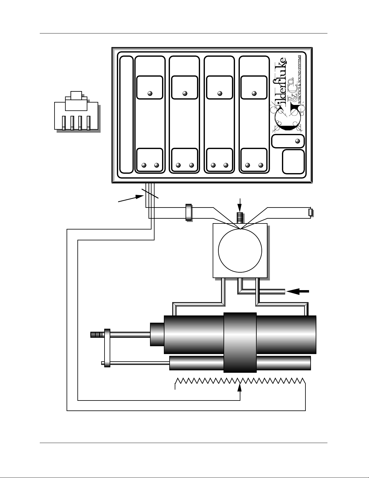
Installation: (Setup for channel 0 output shown. All other channels are identical.)
FACING 4 POSITION
HANDSET PLUG
RED
BLACK
GREEN
YELLOW
FOUR CONDUCTOR
MODULAR STYLE
HANSET WIRE
RED or BLACK
RED or BLACK
WIRE
BREAK
CHANNEL0CHANNEL1CHANNEL2CHANNEL
VALVE
WIRE
BREAK
VALVE
WIRE
BREAK
VALVE
BREAK
VALVE
QUAD EFB CONTROLLER
EXHAUST
(with mufler)
YELLOWYELLOW
GREEN
ATCHLEY
200-PN
204-PN
211-PN
or other >400Ω
valve
C2 C1
WIRE
3
ERROR
J-8
RED
GREENWHITE
80 to 100 PSI
AIR SUPPLY
N/C
2 of 5
CYLINDER
TRANSDUCER
10K ohm resistance
(typical)
Page 3

GILDERFLUKE & CO. ¥ 205 SOUTH FLOWER ST. ¥ BURBANK, CALIF. 91502-2102 ¥ 818/840-9484 ¥ FAX818/840-9485
The cylinder can be virtually any type of double acting cylinder available (rotary, linear, etc.). The
stroke and diameter of the cylinder can be used to determine the size of valve you need to use by
calculating the approximate displacement of the cylinder and comparing it to the cubic feet per minute
(CFM) capacity of the valve.
A number of different styles of position transducers are available. These include standard linear and
rotary potentiometers as well as 'string pots' in which a small steel cable extends to measure distances.
Whatever type of transducer is used, it must be linked to the actuator so that it closely follows the
movement and uses as much of it's 10 Kohm stroke as possible. For any permanent installation you must
use a potentiometer which is made for this type of heavy duty use. Typical life span ratings are in the 2
to 20 million cycle range.
The output which goes to the valve is +/- 10 volts at a current up to 20 ma. This is compatible with
the 250 ohm coils on most servo valves. If air use is a factor in your design, you should use a two stage
valve (like the Atchley 204-PN) in that there quiescent air consumption is lower than a single stage valve
(like the Atchley (200-PN).
Controls:
There are three adjustments available on each of the four EFB circuits. These are:
1) Gain. This controls how much the valve will be opened for a given movement. This control is
bypassed when there is an error condition in the feedback transducer wiring or on power-up.
Turning it counter-clockwise lowers the gain.
2) Velocity. This control limits the maximum amount the valve may open by adding a resistance in
series with the valve. Turning this control counter-clockwise lowers it's effect.
3) Low Gain. This control serves the same function as the normal gain control, but only at the times
when there is an error condition in the transducer wiring or when the EFB controller has just been
powered up. At all other times this control is bypassed. You can use this control to set the speed
at which the movement will go when power is first applied to a circuit or there is a problem in
the transducer wiring. Turning this control counter-clockwise lowers the gain.
Adjustment:
Adjusting an EFB movement is part skill and part art. Unfortunately it must be done to taste, so there
are no set rules about making these adjustments. The following procedure will usually yield satisfactory
results 1:
1) When you first turn on a EFB circuit to start testing it, you should first turn the gain controls all the
way down (counter-clockwise) and the velocity control all the way out (counter-clockwise).
2) Turn the gain control clockwise as you apply a varying command voltage to the movement to
sweep it back and forth. As the gain comes up, you will start to see the valve indicator LEDs start
1
If this is the first time the circuit has been turned on, you may find that the movement turns the
valve on hard in one direction and just wants to stay there. This means that there is something crossed in
the EFB's hookup. To correct this problem you will need to reverse the connections at one and only one
of the following points:
1) Switch the wiring on the transducer. One of the two wires to the transducer is attached to the
wiper. Leave this one alone. The other wire is attached to one end of the resistor. Move this wire
to the opposite end of the resistor (this would be the connection marked 'N/C' on the
illustration).
2) Switch the two wires on the valve. If the valve is opening in the wrong direction, reversing the
two wires to the valve will reverse the direction the valve opens.
3) Switch the plumbing between the valve and the cylinder. Just cross the two hoses at either the
valve or cylinder end of the hookup.
3 of 5
Page 4

GILDERFLUKE & CO. ¥ 205 SOUTH FLOWER ST. ¥ BURBANK, CALIF. 91502-2102 ¥ 818/840-9484 ¥ FAX818/840-9485
to glow as the valve opens and the actuator starts to follow the position commands . Continue
turning the gain up until the movement starts to show signs of oscillation.
3) Turn velocity control clockwise to stop the oscillation. Now turn it back down (counter-clockwise)
until you find the point just above where the movement can be made oscillate by applying fast
moving command voltages.
At this point the movement should be adjusted reasonably well. Depending on the nature of the
movement, you may want to continue to tweak it to taste.
The low gain control is usually set at it's minimum value (fully counter-clockwise). If you want to adjust
it, you will need to force an error condition by temporarily unplugging the wire for that circuit. It will stay
in error condition for about 10 seconds, during which time you can adjust it.
Quad D/A and EFB (ÒGeorge BoardÓ):
This board combines the functions of a Quad D/A converter and a Quad EFB. The adjustments are a
combination of those you would find on both of these other products. The only function which was
eliminated is the Ôlow gainÕ control on the EFB. When a transducer wire break occurs, the gain will
immediately go to its lowest possible value, effectively shutting off the valve. The valve and transducer
connections, indicator LEDs, and adjustments are arranged as follows.
valve
feedback
yellow
red
black
green
CHANNEL 0
level
valve
gain
velocity
ffh level
board error
00h level
As with the regular Quad EFB controller, the wire break error signal from all four channels is summed
to a single indicator LED and output. This is a optoisolated transistor output on pins 4 (collector) and 6
(emitter) of the backplane connector. This output can drive a LED, solid state relay, or small
electromechanical relay. There is also a four pin jumper header, which when two jumpers are installed
horizontally will bring these same signals out to pins 1(collector) and 6 (emitter) on the backplane. These
connect to the white and blue wires on the backplaneÕs RJ-11, which are unused if the rest of the cage
is populated with other Quad D/A&EFB boards or dumb bricks, but which is incompatible with any smart
bricks in the cage. These jumpers are normally left off.
valve
wire break
00h level
CHANNEL 1
gain
velocity
ffh level
level
valve
valve
wire break
CHANNEL 2
velocity
ffh level
00h level
level
gain
valve
valve
wire break
00h level
CHANNEL 3
gain
velocity
ffh level
level
valve
valve
wire break
Note: The Wire Break Collector & Emitter are the 2 wires used by the George Board to transmit
remote wire break indication. If you do not need this feature you can isolate the George board from the
back plane by removing the 2 jumpers located near edge pin #1.
Caution : Never connect edge pins 1& 2 of a George Board to edge pins 1 & 2 of a brick card
unless the 2 jumpers near edge pin 1 are removed.
4 of 5
Page 5

GILDERFLUKE & CO. ¥ 205 SOUTH FLOWER ST. ¥ BURBANK, CALIF. 91502-2102 ¥ 818/840-9484 ¥ FAX818/840-9485
wire # Edge pin # color wire function
J8 Black 1 N/A Wire Break Collector
J8 White 2 N/A Wire Break Emitter
3N/A
4N/A
5N/A
6N/A
7N/A
8N/A
9N/A
10 N/A
#1 11 brown J6 out channel 0 Ground
#2 12 red J6 out channel 0 bit 7
#3 13 orange J6 out channel 0 bit 6
#4 14 yellow J6 out channel 0 bit 5
#5 15 green J6 out channel 0 bit 4
#6 16 blue J6 out channel 0 bit 3
#7 17 violet J6 out channel 0 bit 2
#8 18 gray J6 out channel 0 bit 1
#9 19 white J6 out channel 0 bit 0
#10 20 black J6 out channel 0 + Supply
#11 21 brown J6 out channel 1 Ground
#12 22 red J6 out channel 1 bit 7
#13 23 orange J6 out channel 1 bit 6
#14 24 yellow J6 out channel 1 bit 5
#15 25 green J6 out channel 1 bit 4
#16 26 blue J6 out channel 1 bit 3
#17 27 violet J6 out channel 1 bit 2
#18 28 gray J6 out channel 1 bit 1
#19 29 white J6 out channel 1 bit 0
#20 30 black J6 out channel 1 + Supply
#21 31 brown J6 out channel 2 Ground
#22 32 red J6 out channel 2 bit 7
#23 33 orange J6 out channel 2 bit 6
#24 34 yellow J6 out channel 2 bit 5
#25 35 green J6 out channel 2 bit 4
#26 36 blue J6 out channel 2 bit 3
#27 37 violet J6 out channel 2 bit 2
#28 38 gray J6 out channel 2 bit 1
#29 39 white J6 out channel 2 bit 0
#30 40 black J6 out channel 2 + Supply
#31 41 brown J6 out channel 3 Ground
#32 42 red J6 out channel 3 bit 7
#33 43 orange J6 out channel 3 bit 6
#34 44 yellow J6 out channel 3 bit 5
#35 45 green J6 out channel 3 bit 4
#36 46 blue J6 out channel 3 bit 3
#37 47 violet J6 out channel 3 bit 2
#38 48 gray J6 out channel 3 bit 1
#39 49 white J6 out channel 3 bit 0
#40 50 black J6 out channel 3 + Supply
black 51 brown power supply ground
black 52 red power supply ground
black 53 orange power supply ground
black 54 yellow power supply ground
black 55 green power supply ground
red 56 blue + power supply input
red 57 violet + power supply input
red 58 gray + power supply input
red 59 white + power supply input
red 60 black + power supply input
5 of 5
 Loading...