

Page 1

GILDERFLUKE & CO.• 205 SOUTH FLOWER STREET • BURBANK , CALIFORNIA 91502 • 818/840-9484 • 800/776-5972 • FAX 818/840-9485
AST COAST /FLORIDA O FFICE • 7041 GRAND NATIONAL D RIVE • SUITE 128d • ORLANDO , FL. 32819 • 407/354-5954 • FAX 407/354-5955
E
Mp3-50, Mp3-50/8, Mp3-50/40
Audio & Show Control Systems
Preliminary - printed September 19, 2003
The Mp3-50 is a complete, stand alone Mp3 Audio playback
system. Just add a power supply and your speakers, and it will
play Mp3 audio from the SmartMedia card.
The Mp3-50/8 & Mp3-50/40 add eight or forty digital Show
Control outputs, DMX-512, MIDI or networked RS-422 serial port
input and DMX-512 output to a Mp3-50 player. The Mp3-50/8 &
and
Mp3-50/40 are complete audio
Show Control solutions.
The Mp3-50/8C & Mp3-50/40C adds WWV synchronized
scheduling. This gives you ‘Atomic’ clock accuracy for carillons,
schools, churches, bell towers & industrial annunciator systems.
i of vii
Page 2

GILDERFLUKE & CO .• 205 SOUTH FLOWER STREET • BURBANK , CALIFORNIA 91502 • 818/840-9484 • 800/776-5972 • FAX 818/840-9485
AST COAST /FLORIDA O FFICE • 7041 GRAND NATIONAL D RIVE • SUITE 128d • ORLANDO , FL. 32819 • 407/354-5954 • FAX 407/354-5955
E
Safety Disclaimer: Any electronic or mechanical
system has the potential to fail. Certain applications using Gilderfluke & Company equipment may
involve potential risks of death, personal injury or
severe property or environmental damage (“Critical Application”).
Gilderfluke & Company equipment is not designed, intended, authorized or warranted to be
suitable in life support applications, devices or
systems or other critical applications. Inclusion of
Gilderfluke & Company products in such applications is understood to be fully at the risk of the customer. In order to minimize risks associated with
the customer's applications, adequate design and
operating safeguards should be provided by the
customer to minimize inherent or procedural hazards.
Gilderfluke & Company assumes no liability for
applications assistance, customer produced design, software performance, or infringement of
patents or copyrights. Nor does Gilderfluke &
Company warrant or represent that any license, either express or implied, is granted under any
patent right, copyright, mask work right, or other intellectual property right of Gilderfluke & Company
covering or relating to any combination, machine,
or process in which Gilderfluke & Company products or services might be or are used.
ii of vii
Page 3

GILDERFLUKE & CO .• 205 SOUTH FLOWER STREET • BURBANK , CALIFORNIA 91502 • 818/840-9484 • 800/776-5972 • FAX 818/840-9485
AST COAST /FLORIDA O FFICE • 7041 GRAND NATIONAL D RIVE • SUITE 128d • ORLANDO , FL. 32819 • 407/354-5954 • FAX 407/354-5955
E
Mp3-50, Mp3-50/8 or Mp3-50/40 Overview ........ 1
Mp3-50/8 or Mp3-50/40 Indicators ..................... 5
Mp3 Heart ............................................................................. 6
Mp3 Run ............................................................................... 6
Right ..................................................................................... 6
Left ........................................................................................ 6
Show Control Heart .............................................................. 6
Run ....................................................................................... 6
DMX/MIDI/Serial ................................................................... 6
Board Error ........................................................................... 7
J8 ‘A’, ‘B’, ‘C’, & ‘D’ Input LEDs ............................................. 7
Output LEDs .......................................................................... 7
Fuses .................................................................................... 8
Mp3-50, Mp3-50/8 or Mp3-50/40 Connections .. 9
RS-232 Serial Port ................................................................. 9
USB ....................................................................................... 9
Power Supply ...................................................................... 10
DMX-512/MIDI Serial In ...................................................... 10
DMX-512 ....................................................................... 11
MIDI Notes ..................................................................... 12
Net Serial ....................................................................... 13
IR Mode ......................................................................... 14
None ............................................................................. 16
DMX-512/MIDI Output ........................................................ 16
Status Output ...................................................................... 18
Left Speaker Output ............................................................ 18
Right Speaker Output .......................................................... 18
‘1/4 J6’ Inputs/Outputs ....................................................... 18
Mp3-50 ......................................................................... 18
Mp3-50/8 ...................................................................... 19
Mp3-50/40 .................................................................... 19
Left Line Output ................................................................... 20
Right Line Output ................................................................ 20
J8 ‘A’, ‘B’, ‘C’ & ‘D’ inputs .................................................. 20
‘A’, ‘B’, ‘C’ & ‘D’ Binary ..................................................... 21
‘J6’ Digital Outputs ............................................................. 24
Mp3-50/CC-10 Card Cage ............................... 29
Shows for Mp3-50/8 ........................................... 32
Show Capacities ................................................ 32
iii of vii
Page 4

GILDERFLUKE & CO .• 205 SOUTH FLOWER STREET • BURBANK , CALIFORNIA 91502 • 818/840-9484 • 800/776-5972 • FAX 818/840-9485
AST COAST /FLORIDA O FFICE • 7041 GRAND NATIONAL D RIVE • SUITE 128d • ORLANDO , FL. 32819 • 407/354-5954 • FAX 407/354-5955
E
Mp3-50/8 Show Configurations ............................. 32
One Combined Show Control/Mp3 Control Channel ......... 32
One Show Control, One Mp3 Control Channel .................. 34
One Audio Level Control Channel ...................................... 35
Two Audio Level Control Channels ..................................... 37
DMX-512 w/Overlapping Channels .................................... 39
Sixteen DMX-512 Channels ................................................ 40
Shows for Mp3-50/40 ......................................... 43
Show Capacities ................................................ 43
Mp3-50/40 Show Configurations ........................... 43
One Combined Show Control/Mp3 Control Channel ......... 43
Five Show Control, One Mp3 Control Channel .................. 45
One Audio Level Control Channel ...................................... 46
Two Audio Level Control Channels ..................................... 48
DMX-512 w/Overlapping Channels .................................... 50
Sixteen DMX-512 Channels ................................................ 52
Preparing Animation Data for AutoDownloads 54
Serial Port Commands ...................................... 58
Echo Commands ................................................................ 58
Echo On ........................................................................ 58
Echo Off ........................................................................ 58
Card Status ......................................................................... 59
Card Reset ......................................................................... 61
Start Commands ................................................................. 61
Start Track ...................................................................... 61
Start Global ................................................................... 61
Stop Commands ................................................................. 61
Stop Track ...................................................................... 61
Stop Global ................................................................... 61
Loop Commands ................................................................ 62
Loop Track ..................................................................... 62
Loop Global ................................................................... 62
Stop at End Commands ...................................................... 62
Stop at End Track ........................................................... 62
Stop at End Global ......................................................... 62
Select Show Commands ..................................................... 62
Select Show Track .......................................................... 62
Select Show Global ........................................................ 62
Select Sound Commands ................................................... 63
Select Sound Track ........................................................ 63
iv of vii
Page 5

GILDERFLUKE & CO .• 205 SOUTH FLOWER STREET • BURBANK , CALIFORNIA 91502 • 818/840-9484 • 800/776-5972 • FAX 818/840-9485
AST COAST /FLORIDA O FFICE • 7041 GRAND NATIONAL D RIVE • SUITE 128d • ORLANDO , FL. 32819 • 407/354-5954 • FAX 407/354-5955
E
Select Sound Global ...................................................... 63
Show Pause Commands ..................................................... 63
Pause Show ................................................................... 63
Continue Show .............................................................. 63
AutoDownload .................................................................... 63
RealTime Update ................................................................. 63
Serial Command Summary .................................. 65
Hardware Configuration ................................... 66
Internal/External Power ...................................................... 66
RS-422/Optoisolated ........................................................... 66
Serial Configuration .......................................... 67
Play a Sound ....................................................................... 71
Display Config. from SmartMedia ...................................... 71
Serial Address ................................................................ 71
MIDI channel ................................................................. 71
MIDI 1st Note ................................................................. 72
Repeater Control Channel ............................................ 72
Left Level Control ........................................................... 72
Right Level Control ........................................................ 72
First Animation Channel ................................................. 72
eeFlag0 ......................................................................... 72
eeFlag1 ......................................................................... 73
eeFlag2 ......................................................................... 73
Show Info ............................................................................ 73
Set Time .............................................................................. 74
Stop at End .......................................................................... 74
Loop a Show ....................................................................... 74
Play a Show ........................................................................ 75
Stop Playing ........................................................................ 75
Verify Shows ....................................................................... 75
Software Installation .......................................... 76
Software/Firmware Versions ............................. 78
What to do with a new SmartMedia Card ........ 79
Mp3-50 Configurator ......................................... 81
default settings .................................................. 83
Track Setup ........................................................ 85
Change Track Number ....................................................... 85
Reload Track List From Directory ........................................ 85
v of vii
Page 6

GILDERFLUKE & CO .• 205 SOUTH FLOWER STREET • BURBANK , CALIFORNIA 91502 • 818/840-9484 • 800/776-5972 • FAX 818/840-9485
AST COAST /FLORIDA O FFICE • 7041 GRAND NATIONAL D RIVE • SUITE 128d • ORLANDO , FL. 32819 • 407/354-5954 • FAX 407/354-5955
E
At End ................................................................................. 86
Stop .............................................................................. 86
Next Higher Selection ..................................................... 86
Play Random Selection .................................................. 86
Specific AudioFile .......................................................... 86
Can Step On Track with a new Play request ....................... 86
Track to Play at PowerUp .................................................... 87
PlayList Setup ..................................................... 88
Audio Setup ....................................................... 89
Main Volume Level ............................................................. 89
Half Mute ............................................................................ 89
RealTime Level Control ....................................................... 90
EQ Settings ......................................................................... 90
Enable Power Amplifier ...................................................... 90
Input Setup ........................................................ 91
Binary Select ...................................................... 92
Playback Level .................................................................... 92
Do not change Playback Level ....................................... 93
Fade to Full In ................................................................ 93
Fade to Zero In .............................................................. 93
Fade to ‘Half Mute’ In ..................................................... 93
Start Playing ....................................................................... 93
Whatever is Next ............................................................ 94
Next Higher Track ........................................................... 94
The Same Track Again .................................................... 94
Random Track ............................................................... 94
Specific AudioFile .......................................................... 94
Stop Playing ........................................................................ 94
Stop Now ....................................................................... 95
Stop at End .................................................................... 95
MPU Input Setup ................................................. 96
Binary Select ...................................................... 97
Playback Level .................................................................... 97
Do not change Playback Level ....................................... 98
Fade to Full In ................................................................ 98
Fade to Zero In .............................................................. 98
Fade to ‘Half Mute’ In ..................................................... 98
Start Playing ....................................................................... 98
Whatever is Next ............................................................ 99
Next Higher Track ........................................................... 99
The Same Track Again .................................................... 99
vi of vii
Page 7

GILDERFLUKE & CO .• 205 SOUTH FLOWER STREET • BURBANK , CALIFORNIA 91502 • 818/840-9484 • 800/776-5972 • FAX 818/840-9485
AST COAST /FLORIDA O FFICE • 7041 GRAND NATIONAL D RIVE • SUITE 128d • ORLANDO , FL. 32819 • 407/354-5954 • FAX 407/354-5955
E
Random Track ............................................................... 99
Specific AudioFile .......................................................... 99
Stop Playing ........................................................................ 99
Stop Now ..................................................................... 100
Stop at End .................................................................. 100
MPU Control Setup ............................................ 101
Enable DMX-512 Transmission ......................................... 101
Enable DMX-512 Reception .............................................. 102
Enable DMX-512 Checksums ........................................... 103
Enable MIDI Reception ..................................................... 103
MIDI Notes Trigger Animation Playback ........................... 104
MIDI Channel Number ..................................................... 105
MIDI First Note Number .................................................... 105
Net Serial Mode ................................................................ 105
IR Trigger Mode ................................................................ 106
Repeater MPU Control Channel ....................................... 108
First Animation Channel ................................................... 108
Enable Animation From Flash ........................................... 109
Disable Outputs When Stopped ........................................ 109
Write Protect Flash Memory ............................................. 109
Available Files for Download ............................................ 109
Always Download Current File to Flash on Boot ............... 110
‘Atomic’ Clock Setup .......................................... 111
Disable Schedule Starts .................................................... 114
Reset Clock ...................................................................... 114
Care & Feeding of an ‘Atomic’ Clock .................... 116
alarms .............................................................................. 117
HEXadecimal to Decimal to Percentage ....... 119
vii of vii
Page 8

GILDERFLUKE & CO .• 205 SOUTH FLOWER STREET • BURBANK , CALIFORNIA 91502 • 818/840-9484 • 800/776-5972 • FAX 818/840-9485
AST COAST /FLORIDA O FFICE • 7041 GRAND NATIONAL D RIVE • SUITE 128d • ORLANDO , FL. 32819 • 407/354-5954 • FAX 407/354-5955
E
A note about this manual:
This manual covers the specifics of the
Mp3-50, Mp3-50/8 or Mp3-50/40. To program
the Mp3-50, Mp3-50/8 or Mp3-50/40 you will
need to also need the PC•MACs manual sections that cover the PC•MACs software.
The Mp3-50, Mp3-50/8 or Mp3-50/40 is
typically programmed in ‘Software-only’ or
‘Hardwareless RealTime’ mode. If you are
using the PC•MACs MACs-USB for programming your Mp3-50, Mp3-50/8 or Mp3-50/40
through the DMX-512 input, please refer to the
PC•MACs ‘Unlimited’ mode.
The full PC•MACs manual can be downloaded from our web site at:
http:/ /www.gilderfluke.com
viii of viii
Page 9

GILDERFLUKE & CO .• 205 SOUTH FLOWER STREET • BURBANK , CALIFORNIA 91502 • 818/840-9484 • 800/776-5972 • FAX 818/840-9485
AST COAST /FLORIDA O FFICE • 7041 GRAND NATIONAL D RIVE • SUITE 128d • ORLANDO , FL. 32819 • 407/354-5954 • FAX 407/354-5955
E
Mp3-50, Mp3-50/8 or Mp3-50/40 Overview
The Mp3-30 is a complete audio playback box. It uses a
SmartMedia card to hold audio files stored in the standard Mp3
format. With no moving parts to wear out, the Mp3-50 should well
outlast the speakers it is attached to. The Mp3-50 can be used
singly, or in combination with additional Mp3-50s, Mp3-50/8s or
Mp3-50/40s, BR-SmartMedia cards or any Gilderfluke & Co.
equipment. It can provide the audio for animated shows and
displays, fountains, fireworks, safety announcements, advertising,
alarm systems, window displays special effects, signs, clocks
and carillons, or anything else that needs a sound to be played
back upon command.
Audio is loaded onto the Mp3-50 by first converting it to a
Mp3 format file. There are a number of shareware programs for
doing this, as well as Mp3 encoders included as part of most
audio editing programs
50’s SmartMedia card by temporarily moving the SmartMedia
card to an appropriate slot or reader attached to your computer, or plugging in a USB cable to the front of the Mp3-50 from
your computer. In the later case, the Mp3-50 will appear as a ‘removable disk drive’ on your computer. You can then ‘drag and
drop’ your audio files onto to the SmartMedia card.
1
. The AudioFiles are moved to the Mp3-
The Mp3-50/8 and Mp3-50/40 are complete stand-alone
Show Control and Audio Playback Systems. The Mp3-50/8s or
Mp3-50/40s can be used singly, or in combination with additional Mp3-50s, Mp3-50/8s or Mp3-50/40s, BR-SmartMedia cards or
any Gilderfluke & Co. equipment. It can be used to control animated shows and displays, fountains, fireworks, lighting, sound
systems, simulators, slide and movie projectors, fiber optics, window displays, motors, pneumatic and hydraulic systems, neon
special effects, signs, machines and machine tools in process
control, or anything else that can be controlled by an electrical
1
Contact our sales staff for current Mp3 file converter recommendations.
1 of 119
Page 10

GILDERFLUKE & CO .• 205 SOUTH FLOWER STREET • BURBANK , CALIFORNIA 91502 • 818/840-9484 • 800/776-5972 • FAX 818/840-9485
AST COAST /FLORIDA O FFICE • 7041 GRAND NATIONAL D RIVE • SUITE 128d • ORLANDO , FL. 32819 • 407/354-5954 • FAX 407/354-5955
E
signal.
The Show Control side of the Mp3-50/8 or Mp3-50/40 is pro-
grammed using our PC•MACs Show Control software. While pro-
gramming, data can be sent to the Mp3-50/8 or Mp3-50/40
through its DMX-512 input, ‘Net Serial’ RS-422 port, or RS-232 serial port. Once programed, data is sent to the Mp3-50/8 or Mp3-
50/40 through the PC’s serial port or loaded onto the SmartMedia
card for permanent storage. The Mp3-50/8 or Mp3-50/40 can
then be disconnected from the PC and it will run all by itself.
When used with a ‘Hardwareless RealTime’ licensed copy of
PC•MACs software, Mp3-50/8s or Mp3-50/40s can have their
outputs programmed and updated in real time with just a PC
and a serial connection. When used with the PC•MACs hard-
ware (MACs-SMP or MACs-USB Smpte Card), up to sixty-four Mp3-
50/8s or Mp3-50/40s can be updated in RealTime through the
DMX-512 port.
Features of the Mp3-50/8 or Mp3-50/40 include:
• Stand alone stereo playback of standard Mp3 audio files. Up to
255 different AudioFiles can be selected and played. Sound capacity is only limited by the size of the SmartMedia card installed.
Player supports all standard Mp3 encoding rates, including ‘variable’.
• Two line level outputs (RCA Jacks), or you can use the powerful
11 watt/channel onboard amplifier. In most applications, this amplifier means that all you need to add are appropriate speakers, a
SmartMedia card and a power supply to get up and running.
• Audio data is stored in standard SmartMedia cards. You can use
the built-in USB port to temporarily attach the Mp3-50 to your
computer as a ‘removable hard drive’ or move the SmartMedia
card itself to your computer for high speed ‘drag-n-drop’ downloading. As a bonus feature, you can also use a USB connected
Mp3-50 to download photos from your digital camera, or program SmartMedia cards for any other devices that need them.
This includes the BR-SmartMedia.
• All configuration is done through a user friendly Windows-based
program. You can set the volume, EQ, and what each of sixteen
2 of 119
Page 11

GILDERFLUKE & CO .• 205 SOUTH FLOWER STREET • BURBANK , CALIFORNIA 91502 • 818/840-9484 • 800/776-5972 • FAX 818/840-9485
AST COAST /FLORIDA O FFICE • 7041 GRAND NATIONAL D RIVE • SUITE 128d • ORLANDO , FL. 32819 • 407/354-5954 • FAX 407/354-5955
E
trigger inputs does. Eight of the inputs are from the outside world
through optoisolators, The other eight inputs come directly from
the Show Control side of the Mp3-50/8 or Mp3-50/40, if these
options are installed. Any of the inputs can be used to ramp
audio to preset levels, select and play specific AudioFiles or select
AudioFiles from a preset list or randomizer. Shows can be selected
directly by an input, or using a binary pattern to allow access to
all 255 different possible audio files.
• Mounts stand alone, in 2-3/4” Augat Snap Track, or up to 10 in a
Mp3-50/CC10 cage (Mp3-50 only).
• Runs on any voltage from 12 to 24 volts DC. The Mp3-50s, Mp350/8s or Mp3-50/40s can even be run from batteries! For maxi-
mum output with the onboard amplifier, use 24 volts, and add
approximately 25 Watts (for amplifier) plus your loads when selecting your power supply.
Features of the Mp3-50/8 and Mp3-50/40 include:
• Adds eight (Mp3-50/8) or forty (Mp3-50/40) digital (on/off) Show
Control outputs to a Mp3-50.
• DMX-512 input for programming or controlling the audio play-
back. DMX-512 output for sixteen channel from onboard Show
Control memory or when running from RealTime updates through
the RS-232 serial port.
• Automatic ‘program in place’ download through the serial port on
your PC or through the SmartMedia card. There are no Eproms to
program or install! The amount of time it takes to download shows
the Mp3-50/8 or Mp3-50/40 depends on the length of the
show(s). Short shows take only seconds. Shows that fill the entire
Mp3-50/8s or Mp3-50/40s memory will take about ten minutes to
download. Show audio and animation data can be distributed to
clients by sending out preloaded SmartMedia cards.
• 512 KBytes of nonvolatile Show Control memory. Using all forty
Mp3-50/40 Show Control outputs, this gives a show capacity of
about an hour at thirty updates per second! About five hours for
the Mp3-50/8 using all eight of its outputs! Once downloaded,
show data is retained for approximately forty years, with or without
power applied. Up to 255 individual shows can be loaded onto a
Mp3-50/8 or Mp3-50/40 at one time.
• Mp3 Audio files can be selected, played and audio levels con-
trolled from the Show Control System. Left and Right audio out-
3 of 119
Page 12

GILDERFLUKE & CO .• 205 SOUTH FLOWER STREET • BURBANK , CALIFORNIA 91502 • 818/840-9484 • 800/776-5972 • FAX 818/840-9485
AST COAST /FLORIDA O FFICE • 7041 GRAND NATIONAL D RIVE • SUITE 128d • ORLANDO , FL. 32819 • 407/354-5954 • FAX 407/354-5955
E
puts can be controlled individually, or assigned to the same
analog control channel.
• Two hundred fifty-five shows can be loaded onto a Mp3-50/8 or
Mp3-50/40 at one time. Shows can be accessed sequentially or
directly using the four optoisolated inputs or serial commands
sent through the RS-422 serial port. The ‘Next’ show can be set for
the end of any show, allowing you to loop a single show or build
‘chains’ of shows.
• The Mp3-50/8 or Mp3-50/40 supports update rates from one
frame per second to a maximum of one hundred frames per second. Different shows can each be programmed at different frame
rates. This allows you to program ‘delay’ shows that tick along at a
low frame rate between your main shows, and use very little
memory.
• Four optoisolated inputs to synchronize Mp3-50/8s or Mp350/40s with pushbuttons or other real-time events. Multiple Mp3-
50/8s or Mp3-50/40s can be triggered simultaneously or sequen-
tially. Each Mp3-50/8 or Mp3-50/40 input can be set to start,
stop, pause, continue, or directly select and play a specific show.
Different actions can be requested on each inputs’ opening or
closing edges. If not used for anything else, the four optically isolated inputs can be used to select and play up to fifteen shows at
random through using a binary weighted pattern.
• Shows can also be triggered via the RS-232 or RS-422 serial ports,
MIDI ‘notes’, or IR Triggers.
• Each of the thirty-two outputs is rated for a continuous load of
150 ma., or 500 ma. peak. This is enough to drive small solenoid
valves, relays, LEDs and similar loads. Relays can be used to control higher current or voltage loads (DRV-03 or SSR-FS). If more
than forty outputs are needed, additional Mp3-50/8s or Mp3-
50/40s can be added to give you as many outputs as you need.
• The outputs from a Mp3-50/8 or Mp3-50/40 can be fed to Digital
to Analog converters (like our single channel DAC-08 or four
channel DAC-QUAD) wherever you need 0-10 volt analog control
signals.
• When programming, or when installed as a permanent part of a
larger control system, the Mp3-50/8 or Mp3-50/40 accepts data
through its DMX-512 and RS-422 serial port. This data is used to
update the outputs, and takes precedence over the on board
Flash memory.
4 of 119
Page 13
GILDERFLUKE & CO .• 205 SOUTH FLOWER STREET • BURBANK , CALIFORNIA 91502 • 818/840-9484 • 800/776-5972 • FAX 818/840-9485
AST COAST /FLORIDA O FFICE • 7041 GRAND NATIONAL D RIVE • SUITE 128d • ORLANDO , FL. 32819 • 407/354-5954 • FAX 407/354-5955
E
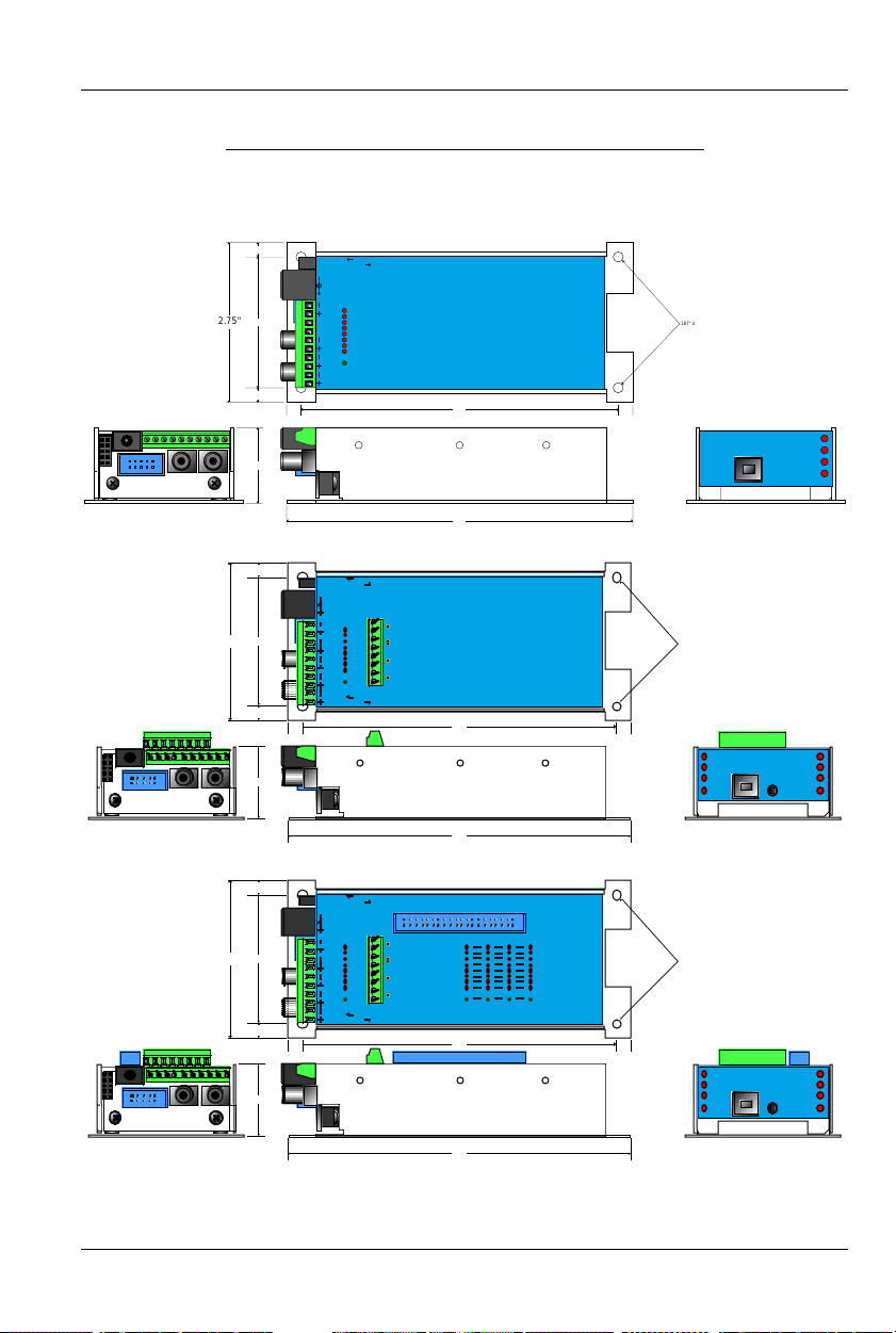
Mp3-50/8 or Mp3-50/40 Indicators
There are only a small number of connections, indicators, and configu-
ration switches on each Mp3-50, Mp3-50/8, Mp3-50/40.
0.25"
2.25"
2.75"
0.25"
0.25" 0.25"
1.3"
Mp3-50/8 (audio & eight Show Control Outputs):
0.25"
2.75" .187" dia.
2.25"
0.25"
0.25" 0.25"
1.3"
Mp3-50 (audio only):
internal
Trigger Power
externa
(switch on bottom)
l
9-24 vdc
Power
9-24 vdc
Power
0
0
1
2
3
4
Status
Out
5
6
Speaker
7
Left
Fuse
Speaker
0
Right
In
Out
Left
Right
9-24 vdc
9-24 vdc
Power
Power
MIDI
MIDI
Speaker
Speaker
internal
external
(switch on bottom)
0
0
1
DMX/
2
3
4
DMX/
5
6
7
Fuse
0
isolated
RS-422
(switch on bottom)
Gilderfluke & Company • Burbank, California
Trigger Power
'A'
'B'
'C'
'D'
DMX/MIDI input
Gilderfluke & Company • Burbank, California
5.5"
5.5"
6"
MP3-50
MP3-50/8
.187" dia.
4 places
4 places
US
B
Show Control Heart
USB
Run
DMX/
MIDI/
Serial
Error
RS-232
MP3 Heart
MP3 Run
MP3 Heart
MP3 Run
Right
Left
Right
Left
6"
Mp3-50/40 (audio & forty Show Control Outputs):
0.25"
2.75" .187" dia.
2.25"
0.25"
0.25" 0.25"
1.3"
In
Out
Left
Right
9-24 vdc
9-24 vdc
Power
Power
MIDI
MIDI
Speaker
Speaker
internal
Trigger Power
external
(switch on bottom)
4
'A'
0
1
DMX/
2
'B'
3
4
DMX/
5
'C'
6
7
'D'
Fuse
4
DMX/MIDI input
isolated
(switch on bottom)
RS-422
3210
7
6
5
4
3
2
1
0
Fuse
3210
Gilderfluke & Company • Burbank, California
5.5"
7
6
5
4
3
2
1
0
Fuse
MP3-50/40
4 places
Show Control Heart
USB
Run
DMX/
MIDI/
Serial
Error
6"
There are up to fifty-seven Status LEDs on the Mp3-50, Mp3-50/8 or
Mp3-50/40:
5 of 119
RS-232
MP3 Heart
MP3 Run
Right
Left
Page 14

GILDERFLUKE & CO .• 205 SOUTH FLOWER STREET • BURBANK , CALIFORNIA 91502 • 818/840-9484 • 800/776-5972 • FAX 818/840-9485
AST COAST /FLORIDA O FFICE • 7041 GRAND NATIONAL D RIVE • SUITE 128d • ORLANDO , FL. 32819 • 407/354-5954 • FAX 407/354-5955
E
1) Mp3 Heart:
(Mp3-50, Mp3-50/8, Mp3-50/40)
The Mp3 ‘heartbeat’
will always flash so that you can see that the audio playback half
of the Mp3-50, Mp3-50/8 or Mp3-50/40 is alive. If this LED does-
n’t flash at least twice per second, you should power down the
Mp3-50, Mp3-50/8 or Mp3-50/40 and check the power supply
and connections to the Mp3-50, Mp3-50/8 or Mp3-50/40.
2) Mp3 Run:
(Mp3-50, Mp3-50/8, Mp3-50/40)
This LED will light to
show that the Mp3 Player is currently playing back an audio file.
3) Right:
(Mp3-50, Mp3-50/8, Mp3-50/40)
This LED flickers to give
you a rough approximation of the audio being played out of the
right side of the audio player. It is upstream of the volume processing done on the Mp3-50, and will not dim to reflect changes
in volume level.
4) Left:
(Mp3-50, Mp3-50/8, Mp3-50/40)
This LED flickers to give you
a rough approximation of the audio being played out of the left
side of the audio player. It is upstream of the volume processing
done on the Mp3-50, and will not dim to reflect changes in volume level.
5) Show Control Heart:
(Mp3-50/8, Mp3-50/40)
The Show Control
‘heartbeat’ will always flash so that you can see that the Show
Control half of the Mp3-50/8 or Mp3-50/40 is alive. If this LED
doesn’t flash at least twice per second, you should power down
the Mp3-50/8 or Mp3-50/40 and check the power supply and
connections to the Mp3-50/8 or Mp3-50/40. During flash memory downloads, this LED will flash alternately with the
DMX/MIDI/Serial LED at twice the normal heartbeat rate.
6) Run:
(Mp3-50/8, Mp3-50/40)
This LED will light to show that the
Show Control half of the Mp3-50/8 or Mp3-50/40 is currently running a preprogrammed show. This LED will also flash at half of the
frame rate (usually 15 Hz) when the Mp3-50/8 or Mp3-50/40 is receiving RealTime update data either through the DMX-512 or serial ports.
7) DMX/MIDI/Serial:
(Mp3-50/8, Mp3-50/40)
This LED will light to
show that the Mp3-50/8 or Mp3-50/40 is receiving RealTime Update data through the DMX-512, MIDI or serial ports. If the Mp3-
50/8 or Mp3-50/40 is receiving show starts from MIDI input, then
this led will flash for about 1/10th of a second each time a ‘start’
happens. During flash memory downloads, this LED will flash alternately with the Show Control Heart LED at twice the normal heartbeat rate.
6 of 119
Page 15

GILDERFLUKE & CO .• 205 SOUTH FLOWER STREET • BURBANK , CALIFORNIA 91502 • 818/840-9484 • 800/776-5972 • FAX 818/840-9485
AST COAST /FLORIDA O FFICE • 7041 GRAND NATIONAL D RIVE • SUITE 128d • ORLANDO , FL. 32819 • 407/354-5954 • FAX 407/354-5955
E
8) Board Error:
(Mp3-50/8, Mp3-50/40)
This LED will flash to show
you that the Mp3-50/8 or Mp3-50/40 has sensed one of the following errors:
a) Just booted: Lights for a short period each time the Mp3-
50/8 or Mp3-50/40’s microcontroller starts up.
b) RealTime DMX-512 Update Error: The optional checksum in
the DMX-512 RealTime update didn’t agree with the data
received.
c) RealTime Serial Update Error: The checksum in the RS-422
serial port RealTime update didn’t agree with the data received.
d) Download Error: There was an error in the data being
downloaded to the Mp3-50/8 or Mp3-50/40.
e) Download Timeout: If the data being downloaded to the
Mp3-50/8 or Mp3-50/40 stops mid-stream, this LED will flash
as the Mp3-50/8 or Mp3-50/40 returns itself to normal operating mode.
f) Data Verification Failure: If you ask the Mp3-50/8 or Mp3-
50/40 to verify the data in its flash memory, and it finds an
error, it will flash this LED as well as displaying an error message on your computer screen.
g) Memory locked: If you try to clear the flash memory or
send a show to the Mp3-50/8 or Mp3-50/40 while the Write
Protect is in the ‘locked’ position.
9) J8 ‘A’, ‘B’, ‘C’, & ‘D’ Input LEDs:
(Mp3-50/8, Mp3-50/40)
four LED will light to show current is flowing through the four Show
Control Trigger inputs. These LEDs are on the input side of the optoisolators, so a dim glow may indicate an input is getting a current, but not necessarily enough to trigger an action. These four
trigger inputs are the only way to use a switch closure input to
start the animated sequence playing on a Mp3-50/8 or Mp3-
50/40.
10) Output LEDs
on Mp3-50/40):
(8 LEDs on Mp3-50, 8 LEDs on Mp3-50/8, 40 LEDs
These LEDs show the current status of the Show
Control digital outputs. If a LED is lit, then that output is ‘ON’. Because the outputs of a Mp3-50/8 or Mp3-50/40 are ‘Open Collector, Switch To Ground’, you can ground out any output pin,
and the appropriate LED will light. This can be useful when diagnosing output wiring problems. If you are commanding ‘on’ an
These
7 of 119
Page 16

GILDERFLUKE & CO .• 205 SOUTH FLOWER STREET • BURBANK , CALIFORNIA 91502 • 818/840-9484 • 800/776-5972 • FAX 818/840-9485
AST COAST /FLORIDA O FFICE • 7041 GRAND NATIONAL D RIVE • SUITE 128d • ORLANDO , FL. 32819 • 407/354-5954 • FAX 407/354-5955
E
output and you don’t see a LED, then the output is probably drawing too much current and the output is ‘self protecting’. Disconnect the load and see if the LED now lights. If it does, then it definitely is an overload problem. If it does not, then try turning ‘on’
some of the other outputs. If they light OK, then the output driver
might be damaged. If they do not, then verify your addressing
and retest.
A Mp3-50 has eight optically isolated trigger inputs which can
be used to select, start and change the audio levels of the audio
half of the Mp3-50 player. These LEDs will light to show trigger inputs being sent into the audio half of the Mp3-50. The only out-
put channel on a Mp3-50/8, and the last output channel on a
Mp3-50/40 are shared with these audio trigger inputs. Normally
these are not used to trigger the audio on a Mp3-50/8 or Mp3-
50/40. The ‘hidden’ MPU trigger inputs from the Show Control half
of the Mp3-50/8 or Mp3-50/40 are normally used instead. This
leaves these eight outputs free to be used as outputs.
11) Fuses
50/40)
(1 LED on Mp3-50, 1 LED on Mp3-50/8, 5 LEDs on Mp3-
: The eight inputs of a Mp3-50 and the eight outputs of the
Mp3-50/8 or Mp3-50/40 make one, eight-bit wide ‘channel’. The
forty outputs of the Mp3-50/8 or Mp3-50/40 are divided into five,
eight-bit wide ‘channels’.
The eight inputs of a Mp3-50, eight outputs of a Mp3-50/8,
and last channel of a Mp3-50/40 are shared with the eight optically isolated inputs to the audio half of the Mp3-50/8 or Mp3-
50/40. This channel, and only this channel can be switched between using ‘internal’ and ‘external’ power using the switch on the
bottom of the unit. This will be lit when there is an external voltage
source present between pins #1 and #10 of the 1/4 J6 input,
when the switch is in the ‘external’ position. If the fuse LED is off for
this channel, check to make sure that this switch is not in the ‘external’ position if you are not feeding this channel an external
voltage source.
Each channel is fused for approximately one Amp of continu-
ous current. These LEDs light to show if the fuses are OK. If any are
out, then a short circuit (or too heavy of a load) is dragging the
outputs down and causing the fuse to open. The fuses are actually ‘PTC fuses’, which act more like circuit breakers. Once the overload is removed, they reset.
8 of 119
Page 17
GILDERFLUKE & CO .• 205 SOUTH FLOWER STREET • BURBANK , CALIFORNIA 91502 • 818/840-9484 • 800/776-5972 • FAX 818/840-9485
AST COAST /FLORIDA O FFICE • 7041 GRAND NATIONAL D RIVE • SUITE 128d • ORLANDO , FL. 32819 • 407/354-5954 • FAX 407/354-5955
E
Mp3-50, Mp3-50/8 or Mp3-50/40 Connections
1) RS-232 Serial Port:
(Mp3-50/8, Mp3-50/40)
The serial command
set is identical to, and compatible with all of the RS-422 Serial
Ports used on Gilderfluke & Company products. One difference
between the Mp3-50/8 or Mp3-50/40 and most of our products is
that the serial port is the primary method used to configure it. A
Mp3-50/8 or Mp3-50/40 is normally configured through the ‘Mp3
Configurator’ program which is also used to configure the Mp3
half. This configuration is downloaded to the Show Control half of
the Mp3-50/8 or Mp3-50/40 each time the Mp3-50/8 or Mp3-
50/40 is turned on. The Mp3-50/8 or Mp3-50/40 has a serial ‘configuration’ mode which will allow you to check and modify the status and configuration of the Show Control half of the Mp3-50/8
or Mp3-50/40. This is used to configure the animation half of a
Mp3-50/8 or Mp3-50/40 if the audio half is not yet, or never is
going to be used.
The serial data signals from the Mp3-50/8s or Mp3-50/40s
are brought out on a 1/8” three conductor ‘stereo’ socket. Its pin
out and cross connect to the standard serial port on a PC is as
follows:
IBM AT
Serial
gnd
Txd
Rxd
9
8
7
6
5
4
3
2
1
(ring)
(sleeve)
(tip)
2
3
1
The Mp3-50/8 or Mp3-50/40 expects to see the serial data in
the following format:
ONE START BIT
EIGHT DATA BITS
ONE STOP BIT
2) USB:
(Mp3-50, Mp3-50/8, Mp3-50/40)
The standard USB port can
be used to download audio files and configurations to the Mp3-
50/8 or Mp3-50/40. Alternatively, the SmartMedia card can be removed from the Mp3-50/8 or Mp3-50/40 and plugged into an
appropriate slot on your computer to configure and load audio
9 of 119
Page 18

GILDERFLUKE & CO .• 205 SOUTH FLOWER STREET • BURBANK , CALIFORNIA 91502 • 818/840-9484 • 800/776-5972 • FAX 818/840-9485
AST COAST /FLORIDA O FFICE • 7041 GRAND NATIONAL D RIVE • SUITE 128d • ORLANDO , FL. 32819 • 407/354-5954 • FAX 407/354-5955
E
files onto it. Once the Mp3-50/8 or Mp3-50/40 software drivers
have been loaded onto your computer, you can plug a USB
cable from your computer to the Mp3-50/8 or Mp3-50/40. After
a few moments the Mp3-50/8 or Mp3-50/40 will appear on your
computer as a ‘removable hard disk drive’. You can then access
the SmartMedia card in the Mp3-50/8 or Mp3-50/40 just as you
would any disk that is attached to your computer. You can even
use the Mp3-50/8 or Mp3-50/40 to download pictures from the
SmartMedia card you normally use in your digital camera.
3) Power Supply:
(Mp3-50, Mp3-50/8, Mp3-50/40)
The power supply connections to the Mp3-50, Mp3-50/8 or Mp3-50/40 are
available on both a 2.1 mm power jack and two of the screw terminal positions. For mobile, permanent or higher current applications, you may wish to use the screw terminals instead of the 2.1
mm power jack. It is less prone to being accidentally unplugged
or vibrating loose. The screw terminals are also a very convenient
place to ‘steal’ a little ‘juice’ to power the four optically isolated inputs.
If you are not using the onboard amplifier, the Mp3-50, Mp3-
50/8 or Mp3-50/40 can be run from any supply voltage from 9
VDC to 24 VDC. If you are using the onboard amplifier and want
to reach the maximum possible power from the amplifier, you will
need to run the Mp3-50, Mp3-50/8 or Mp3-50/40 from 24 VDC.
The Show Control outputs are powered from this supply connection as well. If you are driving 24 VDC loads, then run the
Mp3-50, Mp3-50/8 or Mp3-50/40 on 24 VDC. If your loads require 12 VDC, then run the Mp3-50, Mp3-50/8 or Mp3-50/40 on
12 VDC.
The power supply connections are protected from reversed
polarity. An idle Mp3-50, Mp3-50/8 or Mp3-50/40 draws only
about ??? milliamperes. The onboard amplifier and loads which
the Mp3-50, Mp3-50/8 or Mp3-50/40 is controlling will usually
draw far more current than the Mp3-50, Mp3-50/8 or Mp3-50/40
itself. If you are using the onboard amplifier, you should allow at
least 25 Watts for it, in addition to the current for controlling your
animation loads (Mp3-50/8 and Mp3-50/40). If you hear ‘clicks’ or
clipping on your amplifier outputs, then your power supply capacity may need to be increased.
4) DMX-512/MIDI Serial In:
(Mp3-50/8, Mp3-50/40)
Two position
Screw Terminals. This input can be selected for RS-422 (high-z) or
optoisolated (low-z) input by a switch on the bottom of the unit.
10 of 119
Page 19

GILDERFLUKE & CO .• 205 SOUTH FLOWER STREET • BURBANK , CALIFORNIA 91502 • 818/840-9484 • 800/776-5972 • FAX 818/840-9485
AST COAST /FLORIDA O FFICE • 7041 GRAND NATIONAL D RIVE • SUITE 128d • ORLANDO , FL. 32819 • 407/354-5954 • FAX 407/354-5955
E
DMX-512 is normally used with the ‘RS-422’ position. MIDI will
only
work in the ‘optoisolated’ position. The Net Serial or IR Trigger
modes are normally used in the ‘RS-422’ position, but will actually
work in either position.
If you need to optically isolate the signal, but feed multiple
Mp3-50/8 or Mp3-50/40, you can use a single Mp3-50/8 or
Mp3-50/40 as an isolator/buffer: The external signal can be fed
into one of the ‘optoisolated’ DMX/MIDI inputs on any one Mp350/8 or Mp3-50/40, and the other units fed in parallel from the
DMX/MIDI output from that first unit. All of these other ‘downstream’ Mp3-50/8s or Mp3-50/40s should have their inputs set for
RS-422.
This connection has five possible modes of operation. These
are selected through the ‘Mp3 Configurator’ program.
a) DMX-512: The switch on the bottom of the Mp3-50 should
be in the RS-422/High-z position to be used for DMX-512.
The Mp3-50/8 or Mp3-50/40 will stop playing any shows
from the onboard flash memory as soon as valid DMX-512
signal is received.
The DMX-512 standard was developed by the United
States Institute for Theatrical Technology (USITT) for a high
speed (250 KBaud) asynchronous serial data link. Although it
was originally designed for controlling light dimmers, it is
now supported by hundreds of suppliers throughout the
world for controlling all kinds of theatrical equipment.
Even though the DMX-512 standard calls for 512 channels of data, the DMX-512 transmission from PC•MACs is
limited to 256 eight-bit wide channels. If you have enabled
the DMX-512 checksum, you can address your DMX-512
compatible output devices to respond to any address between 0 and 255. Addresses above the 256th are used in
PC•MACs for transmitting a checksum. The Mp3-50/8 or
Mp3-50/40 can use this to verify that the data received
from PC•MACs has no transmission errors in it. If you ad-
dress a light dimmer or other DMX-512 device to addresses
256 or 257, you will see this verification data displayed as a
flickering pattern.
If you have NOT selected DMX-512 checksums, the
‘Mp3 Configurator’ will allow you to set the addresses for
DMX-512 to any address from 1 through 512. Address ‘1’ is
11 of 119
Page 20

GILDERFLUKE & CO .• 205 SOUTH FLOWER STREET • BURBANK , CALIFORNIA 91502 • 818/840-9484 • 800/776-5972 • FAX 818/840-9485
AST COAST /FLORIDA O FFICE • 7041 GRAND NATIONAL D RIVE • SUITE 128d • ORLANDO , FL. 32819 • 407/354-5954 • FAX 407/354-5955
E
equivalent to address ‘0’ if you were using checksums.
The DMX-512 checksums should be enabled if the DMX-
512 that is sent to the Mp3-50/8 or Mp3-50/40 is coming
from ANY piece of Gilderfluke & Company equipment. The
checksums assure that the Mp3-50/8 or Mp3-50/40 will not
update its outputs on ‘bad’ data.
b) MIDI Notes: The switch on the bottom of the Mp3-50 must
be in the optoisolated/Low-z position to be used for MIDI.
The MIDI should be fed to the Mp3-50/8 or Mp3-50/40 as
follows:
MIDI pin #1 = no connection
MIDI pin #2 = no connection
MIDI pin #3 = no connection
MIDI pin #4 into - DMX/MIDI In
MIDI pin #5 into + DMX/MIDI In
The Mp3-50/8 or Mp3-50/40 will respond to MIDI ‘Note
On’, ‘Note Off’, ‘Reset’, ‘All Notes Off’ and ‘All Sounds Off’.
Running commands for ‘Note On’ and ‘Note Off’ commands are accepted. All other defined MIDI commands
should be received and properly ignored. There are two
ways the Mp3-50/8 or Mp3-50/40 can be configured to re-
spond to MIDI Note commands.
1) When ‘MIDI Notes Trigger Animation’ checkbox is OFF,
then MIDI is used to directly access the Show Control
Outputs and Mp3 audio files:
a) Any MIDI notes which are below the number
you have set for the ‘MIDI Offset’ are ignored.
b) The next eight (Mp3-50/8) or forty (Mp3-50/40)
MIDI notes are mapped directly to the 8/40
Show Control outputs. These can be used to
ring mechanical bells or control animation directly from MIDI notes.
c) The next eight MIDI notes are sent to the ‘MPU
Interface’ to select and trigger audio files,
mute, and otherwise control the Mp3 Player.
d) The remaining notes are used to directly select
and play individual AudioFiles stored on the
Mp3 Player. Only note ‘On’ MIDI commands will
have any effect on selecting and playing AudioFiles. The ‘velocity’ of the note will set the
playback level of the triggered AudioFile, if Re-
12 of 119
Page 21

GILDERFLUKE & CO .• 205 SOUTH FLOWER STREET • BURBANK , CALIFORNIA 91502 • 818/840-9484 • 800/776-5972 • FAX 818/840-9485
AST COAST /FLORIDA O FFICE • 7041 GRAND NATIONAL D RIVE • SUITE 128d • ORLANDO , FL. 32819 • 407/354-5954 • FAX 407/354-5955
E
alTime level control has been enabled on the
Mp3 Player.
The DMX/MIDI/Serial LED will be lit once MIDI is received through this port. This LED will remain on for
approximately 10 seconds after the MIDI is removed
from the Mp3-50/8 or Mp3-50/40. The Mp3-50/8 or
Mp3-50/40 will stop playing any shows from the onboard flash memory as soon as valid MIDI signal is received. It will not restart automatically if the MIDI signal is removed.
2) When ‘MIDI Notes Trigger Animation’ checkbox is ON,
then MIDI notes are used to directly access Animation
sequences stored in the flash on the Mp3-50/8 or
Mp3-50/40. These sequences in turn can access
audio files on the Mp3 Player, as well as controlling
the Show Control outputs. When operating in this
mode:
a) Any MIDI notes which are below the number
you have set for the ‘MIDI Offset’ are ignored.
b) The remaining notes are used to directly select
and play individual animation sequences stored
on the Show Control half of the Mp3-50/8 or
Mp3-50/40. These animation sequences can in
turn select and play audio files and control
audio levels on the Mp3 Player. Only ‘Note On’
commands are used to select and play animated shows when operating in this mode.
The DMX/MIDI/Serial LED will be flash for 1/10 second each time a preprogrammed show is started by a
MIDI note. The Show Control side of the Mp3-50/8 or
Mp3-50/40 can still accept starts though the serial
port and four trigger inputs while operating in this
mode.
c) Net Serial: The Optoisolated/RS-422 switch on the bottom
of the Mp3-50 can be in either position. If feeding multiple
Mp3-50/8 or Mp3-50/40, then the ‘RS-422’ position should
be used.
One big disadvantage of the RS-232 serial port on the
Mp3-50/8 or Mp3-50/40 is that only one Mp3-50/8 or Mp350/40 can be attached to the same serial port at the same
time. This is the unfortunate nature of a RS-232 port. If you
had a bunch of Mp3-50s in the same system, this could
13 of 119
Page 22

GILDERFLUKE & CO .• 205 SOUTH FLOWER STREET • BURBANK , CALIFORNIA 91502 • 818/840-9484 • 800/776-5972 • FAX 818/840-9485
AST COAST /FLORIDA O FFICE • 7041 GRAND NATIONAL D RIVE • SUITE 128d • ORLANDO , FL. 32819 • 407/354-5954 • FAX 407/354-5955
E
quickly chew up a lot of serial ports! Most of our other products use RS-422 serial ports. Along with being able to run
your wires up to a mile (RS-232 is limited to about 50 feet if
the wind is blowing in the right direction), RS-422 allows lots
of devices to be attached to the same serial port at the
same time.
Because it is not uncommon to access and control a
large number of repeaters on the same serial line, the DMX512/MIDI input can be selected to turn the DMX-512/MIDI
port into a multidrop Serial network. This mode parallels the
data received on the DMX-512/MIDI input pins with the serial data received on the regular RS-232 serial port. The serial
data is still output from the Mp3-50/8 or Mp3-50/40 still
comes ONLY through the RS-232 serial port on the front to
the unit.
This serial port can be used to select and play shows,
check the status of a card, or AutoDownload shows from
any point on the network. Since it is 100% compatible with
the RS-422 serial ports on all other Gilderfluke & Company
equipment, a multidrop network can consist of up to 256
Mp3-50/8 or Mp3-50/40 and any other Gilderfluke & Company devices. The only requirement is that they all be set to
unique addresses.
Since RS-422 is probably the most widely used of industrial data networks, a myriad of other pieces of equipment
are available which will also work with the Net Serial mode.
These allow you to do tricks like controlling the Mp3-50/8 or
Mp3-50/40 through a wireless modem using off-the-shelf
hardware.
A typical application is to use a touch screen operator
interface to access and play shows. These generally use a
user definable graphical interface. You pretty much draw a
button, and then attach a string to it. When this on-screen
button is pushed, this string is sent out to control the downstream equipment.
d) IR Mode: The Optoisolated/RS-422 switch on the bottom of
the Mp3-50 can be in either position, but RS-422 is preferred. This turns on a special serial port mode on the Mp3-
50/8 or Mp3-50/40 which allows it to be used with our InfraRed Transmitters and Receivers. The IR Remote mode is
typically used to trigger an animation or sound system
14 of 119
Page 23

GILDERFLUKE & CO .• 205 SOUTH FLOWER STREET • BURBANK , CALIFORNIA 91502 • 818/840-9484 • 800/776-5972 • FAX 818/840-9485
AST COAST /FLORIDA O FFICE • 7041 GRAND NATIONAL D RIVE • SUITE 128d • ORLANDO , FL. 32819 • 407/354-5954 • FAX 407/354-5955
E
mounted on a vehicle, turntable, or other installation where
wires can’t be used. The DMX-512 /MIDI port is forced to
1200 baud and all serial port commands are disabled on
the DMX-512/MIDI port when this mode is ON. Any binary
show number received by the serial port for more than ten
times will trigger the requested show. Typically the transmit-
ters are placed along the path of the vehicle’s travel to trig-
ger the appropriate animation sequences at the appropri-
ate times.
The connections to the IR Remote Receiver are as fol-
lows (view is facing end of cable with latch up):
NAME COLOR SIGNAL FUNCTION
LEFT Ground WHITE Ground
n/c BLACK no connection
n/c RED no connection
- TxD GREEN - DMX-512/MIDI Input
+ TxD YELLOW + DMX-512/MIDI Input
RIGHT Ground BLUE Ground
In addition to these connections, the IR Receiver requires a 7 to 24 volt DC power supply connection. This is
normally attached to the two pads marked “+” and “-” on
the receiver. A jumper option allows you to bring this in
through the blue wire on the RJ-11 connector.
When in this mode the ‘Early Starts’ for all shows should
be set to ‘NOT Steppable’. If this is not done, then the same
show will be retriggered over and over again until the vehicle moves out of the IR beam from the transmitter.
The IR Transmitter has an eight position dipswitch which
sets which show it selects. The lower nibble of the address
are set with the first four switches, and the upper nibble is
set with the last four. Valid show numbers are 01h through
FFh:
15 of 119
Page 24

GILDERFLUKE & CO .• 205 SOUTH FLOWER STREET • BURBANK , CALIFORNIA 91502 • 818/840-9484 • 800/776-5972 • FAX 818/840-9485
AST COAST /FLORIDA O FFICE • 7041 GRAND NATIONAL D RIVE • SUITE 128d • ORLANDO , FL. 32819 • 407/354-5954 • FAX 407/354-5955
E
SWITCH #1 SWITCH #2 SWITCH #3 SWITCH #4 LOWER NIBBLE OF ADDRESS
OFF OFF OFF OFF x0h
ON OFF OFF OFF x1h
OFF ON OFF OFF x2h
ON ON OFF OFF x3h
OFF OFF ON OFF x4h
ON OFF ON OFF x5h
OFF ON ON OFF x6h
ON ON ON OFF x7h
OFF OFF OFF ON x8h
ON OFF OFF ON x9h
OFF ON OFF ON xAh
ON ON OFF ON xBh
OFF OFF ON ON xCh
ON OFF ON ON xDh
OFF ON ON ON xEh
ON ON ON ON xFh
SWITCH #5 SWITCH #6 SWITCH #7 SWITCH #8 UPPER NIBBLE OF ADDRESS
OFF OFF OFF OFF 0xh
ON OFF OFF OFF 1xh
OFF ON OFF OFF 2xh
ON ON OFF OFF 3xh
OFF OFF ON OFF 4xh
ON OFF ON OFF 5xh
OFF ON ON OFF 6xh
ON ON ON OFF 7xh
OFF OFF OFF ON 8xh
ON OFF OFF ON 9xh
OFF ON OFF ON Axh
ON ON OFF ON Bxh
OFF OFF ON ON Cxh
ON OFF ON ON Dxh
OFF ON ON ON Exh
ON ON ON ON Fxh
e) None: If the DMX-512/MIDI input is not being used, then the
DMX-512 transmission is enabled on the DMX-512/MIDI output terminals.
5) DMX-512/MIDI Output:
(Mp3-50/8, Mp3-50/40)
Two position
Screw Terminals. If any of the modes where the DMX-512/MIDI
input is being used (DMX-512 Input, MIDI Input, Net Serial or IR
Trigger), this pair of screw terminals will retransmit whatever comes
in on the DMX-512/MIDI inputs. This works something like the ‘MIDI
16 of 119
Page 25

GILDERFLUKE & CO .• 205 SOUTH FLOWER STREET • BURBANK , CALIFORNIA 91502 • 818/840-9484 • 800/776-5972 • FAX 818/840-9485
AST COAST /FLORIDA O FFICE • 7041 GRAND NATIONAL D RIVE • SUITE 128d • ORLANDO , FL. 32819 • 407/354-5954 • FAX 407/354-5955
E
Through’ port on a MIDI device, where no content changes take
place in the data as it passes through the Mp3-50/8 or Mp3-
50/40. The data is simply buffered and retransmitted.
The output levels on these pins is RS-422. It can be used directly to control other RS-422 devices. For MIDI, you should add a
pair of 220 Ohm resistors in series with the two output wires, but
this is not strictly necessary (there are already resistors in the MIDI
devices which may be receiving this signal).
The MIDI should be wired from the Mp3-50/8 or Mp3-50/40 to
the next MIDI device as follows:
MIDI pin #1 = no connection
MIDI pin #2 = Shield (ground)
MIDI pin #3 = no connection
MIDI pin #4 from - DMX/MIDI Out
MIDI pin #5 from + DMX/MIDI Out
If none of the serial Receive modes of the Mp3-50/8 or Mp3-
50/40 (DMX-512 Input, MIDI Input, Net Serial or IR Trigger) are
being used, then the serial port is turned around and used to
transmit DMX-512. Data for this DMX-512 output stream comes
from either the RS-232 serial port if the Mp3-50/8 or Mp3-50/40 is
being fed RealTime update messages, or the Show Control flash
memory, if shows have been programmed into the Mp3-50/8 or
Mp3-50/40.
DMX-512 transmission is limited to sixteen, eight bit wide
channels. The addresses of these DMX-512 channels are set in
one of two ways:
a) If running from RealTime updates through the RS-232 serial
port, the DMX-512 data will always start with channel ‘0’
(which is channel ‘1’ on most dimmers). Data after the first
channel will be padded with ‘0’ values through the 256th
byte, and then followed by two checksum bytes.
The Show Control Outputs, Audio Level Control, And Repeater Control channels typically overlap with some of the
lighting control channels when operated in this mode.
b) If running from a show file which has been AutoDownload-
ed to the Mp3-50/8 or Mp3-50/40’s Flash memory, the ‘First
address’ of the downloaded data will be the first DMX-512
channel to have your programmed data in it. Channels before and after these sixteen channels will be padded with ‘0’
17 of 119
Page 26

GILDERFLUKE & CO .• 205 SOUTH FLOWER STREET • BURBANK , CALIFORNIA 91502 • 818/840-9484 • 800/776-5972 • FAX 818/840-9485
AST COAST /FLORIDA O FFICE • 7041 GRAND NATIONAL D RIVE • SUITE 128d • ORLANDO , FL. 32819 • 407/354-5954 • FAX 407/354-5955
E
values up until the 256th bytes sent, then followed with a
two byte checksum.
The Show Control Outputs, Audio Level Control, And Re-
peater Control channels often overlap with some of the
lighting control channels when operated in this mode. If
you don’t want to do this, you can actually use all sixteen
DMX-512 channels for lighting control if you address your
Show Control Outputs, Audio Level Control, and Repeater
Control channels
after
the sixteen lighting control channels.
Of course this will eat up your Flash memory capacity
mighty quickly.
6) Status Output:
(Mp3-50)
Two position Screw Terminals. This output
is the uncommitted collector (+) and emitter (-) of a darlington
optoisolator. It can be used as a remote ‘audio running’ indicator
for an external system. The current capability of this output is only
about 50 ma.. It can be used to drive LEDs and solid state relays,
but not heavy or inductive loads.
7) Left Speaker Output:
(Mp3-50, Mp3-50/8, Mp3-50/40)
Two position Screw Terminals. This is one of the two outputs of the Mp3-
50, Mp3-50/8 or Mp3-50/40 ‘s onboard amplifier. It can be used
with any speakers from 4 ohms upwards. The amplifier is rated for
a maximum output of 11 Watts per channel. This is plenty powerful for most applications. External amplifiers can be fed from the
Line Level Outputs if more power than this is needed.
8) Right Speaker Output:
(Mp3-50, Mp3-50/8, Mp3-50/40)
Two position Screw Terminals. This is one of the two outputs of the Mp3-
50, Mp3-50/8 or Mp3-50/40’s onboard amplifier. It can be used
with any speakers from 4 ohms upwards. The amplifier is rated for
a maximum output of 11 Watts per channel. This is plenty powerful for most applications. External amplifiers can be fed from the
Line Level Outputs if more power than this is needed.
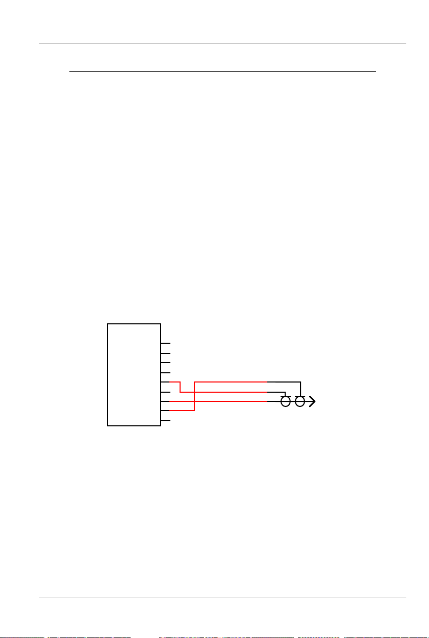
9) ‘1/4 J6’ Inputs/Outputs: Ten Position IDS Connector. This connection serves two completely different functions, using the very
same pins:
Mp3-50: These pins are used to connect to the eight optically
isolated trigger inputs which are used to select AudioFiles,
start, mute, half mute, pause, or unmute the Mp3 Player.
What each of these pins will do is set using the ‘Mp3 Con-
figurator’ program. These inputs CAN NOT be used to start
an animation sequence running on the Show Control half
18 of 119
Page 27
GILDERFLUKE & CO .• 205 SOUTH FLOWER STREET • BURBANK , CALIFORNIA 91502 • 818/840-9484 • 800/776-5972 • FAX 818/840-9485
AST COAST /FLORIDA O FFICE • 7041 GRAND NATIONAL D RIVE • SUITE 128d • ORLANDO , FL. 32819 • 407/354-5954 • FAX 407/354-5955
E
of a Mp3-50/8 or Mp3-50/40.
Mp3-50/8: This connector is used for the optically isolated trig-
ger inputs of the Mp3 Player, but these are not normally
used to control the Mp3 Player. The same connector is also
used as the eight Show Control outputs. The inputs to the
Mp3 Player are typically configured not to do anything,
and the ‘MCU’ Show Control Trigger channel is used instead
for controlling the Mp3 Player. This leaves all eight of these
pins available for Show Control Outputs.
If you need to use a switch input to mute or stop the
audio, it can still be wired into this connector. The input to
the Mp3 Player is then configured for the desired function.
The corresponding Show Control output is left unprogrammed, so that show data does not interfere with the operation of the Mp3 Player.
Mp3-50/40: This connector is also used as the optically isolated
trigger inputs the Mp3 Player, and the last eight of the forty
Show Control outputs. Other than that, it is identical to a
Mp3-50/8.
(Brown) PIN #1
GROUND
(Brown) PIN #1
GROUND
(red) PIN #2
(orange) PIN #3
(yellow) PIN #4
(green) PIN #5
(blue) PIN #6
(violet) PIN #7
(grey) PIN #8
(white) PIN #9
(black) PIN #10
DATA BIT 7
DATA BIT 6
DATA BIT 5
DATA BIT 4
DATA BIT 3
DATA BIT 2
DATA BIT 1
DATA BIT 0
+ 5 to 24 VDC SUPPLY
(red) PIN #2
(orange) PIN #3
(yellow) PIN #4
(green) PIN #5
(blue) PIN #6
(violet) PIN #7
(grey) PIN #8
(white) PIN #9
(black) PIN #10
Internal PowerExternal Power
For a Mp3-50, the 1/4 J6 input is strictly a Mp3 input. It is opti-
cally isolated. It can be set to run from an external power source
or the same power as the Mp3-50, Mp3-50/8 or Mp3-50/40 (de-
fault configuration). This is selected by moving the switch on the
bottom of the Mp3-50, Mp3-50/8 or Mp3-50/40. The ‘external’
19 of 119
DATA BIT 7
DATA BIT 6
DATA BIT 5
DATA BIT 4
DATA BIT 3
DATA BIT 2
DATA BIT 1
DATA BIT 0
SUPPLY (not used)
Page 28
GILDERFLUKE & CO .• 205 SOUTH FLOWER STREET • BURBANK , CALIFORNIA 91502 • 818/840-9484 • 800/776-5972 • FAX 818/840-9485
AST COAST /FLORIDA O FFICE • 7041 GRAND NATIONAL D RIVE • SUITE 128d • ORLANDO , FL. 32819 • 407/354-5954 • FAX 407/354-5955
E
setting is used when you want to completely isolate the Mp3-50,
Mp3-50/8 or Mp3-50/40 from the switch closures that control it.
On a Mp3-50/8 or Mp3-50/40, this input/output is almost always run in the ‘Internal’ power mode. The only exception to this is
if you are going to be running the devices controlled by these
eight Show Control outputs from a different voltage from the rest
of the Mp3-50/8 or Mp3-50/40. As an example, it the Mp3-50/8
or Mp3-50/40 is running from 24 VDC, and you need to control
eight 12 VDC relays, you can power this one port from a 12 VDC
power supply separate from the main one (you will need to connect the grounds of the two power supplies).
10) Left Line Output: Female RCA jack. This is one of the two line level
outputs from the Mp3 Player. It is used for attaching an external
amplifier to the Mp3-50, Mp3-50/8 or Mp3-50/40.
11) Right Line Output: Female RCA jack. This is one of the two line
level outputs from the Mp3 Player. It is used for attaching an external amplifier to the Mp3-50, Mp3-50/8 or Mp3-50/40.
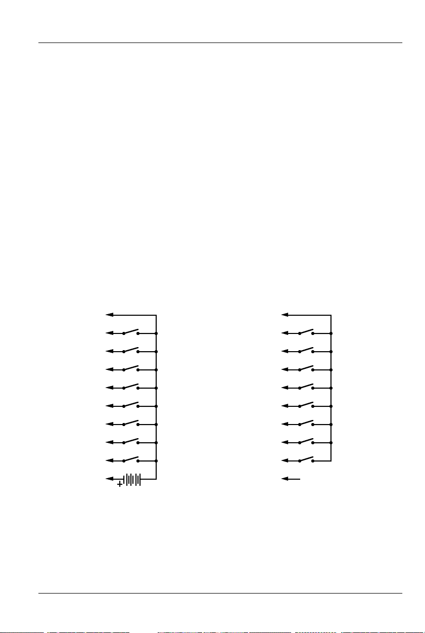
12) J8 ‘A’, ‘B’, ‘C’ & ‘D’ inputs: These are four optically isolated digital
inputs which can be used to start, stop, pause or select specific
show sequences to play on the Show Control of the Mp3-50/8 or
Mp3-50/40.
+5 to 24 VDC SUPPLY
- 'A'/Green Input
+ 'A'/Green Input
+5 to 24 VDC SUPPLY
- 'A'/Green Input
+ 'A'/Green Input
- 'B'/Red Input
+5 to 24 VDC SUPPLY
+ 'B'/Red Input
- 'C'/Blue Input
+5 to 24 VDC SUPPLY
+ 'C'/Blue Input
- 'D'/White Input
+5 to 24 VDC SUPPLY
+ 'D'/White Input
Switching Negative Side
+5 to 24 VDC SUPPLY
- 'B'/Red Input
+ 'B'/Red Input
+5 to 24 VDC SUPPLY
- 'C'/Blue Input
+ 'C'/Blue Input
+5 to 24 VDC SUPPLY
- 'D'/White Input
+ 'D'/White Input
Switching Positive Side
20 of 119
Page 29

GILDERFLUKE & CO .• 205 SOUTH FLOWER STREET • BURBANK , CALIFORNIA 91502 • 818/840-9484 • 800/776-5972 • FAX 818/840-9485
AST COAST /FLORIDA O FFICE • 7041 GRAND NATIONAL D RIVE • SUITE 128d • ORLANDO , FL. 32819 • 407/354-5954 • FAX 407/354-5955
E
In most cases, you will simply be ‘borrowing the power for
these switches from the adjacent power terminals:
Trigger Power
internal
(switch on bottom)
external
9-24 vdc
ground
Switch 'A'
Switch 'B'
Switch 'C'
Switch 'D'
Power
9-24 vdc
Power
MIDI
In
MIDI
Out
Speaker
Left
Speaker
Right
DMX/
DMX/
4
0
1
2
3
4
5
6
7
Fuse
4
RS-422
isolated
'A'
'B'
'C'
'D'
DMX/MIDI input
(switch on bottom)
32 10
7
6
5
4
3
2
1
0
Fuse
32 10
Gilderfluke & Company • Burbank, California
7
6
5
4
3
2
1
0
Fuse
MP3-50/40
Any event can be triggered on either the ‘closing’ or ‘opening’
edge of any input. A ‘closing’ is when you apply a voltage to an
input. An ‘opening’ is when that voltage is removed. The inputs
can be triggered on any voltage from 12 to 24 VDC. If you don’t
have an external source of power for these two inputs, you can
‘steal’ some juice from the Mp3-50/8s or Mp3-50/40s power supply connections.The two screw terminals with the Mp3-50’s power
on them are immediately adjacent to these inputs for just this purpose.
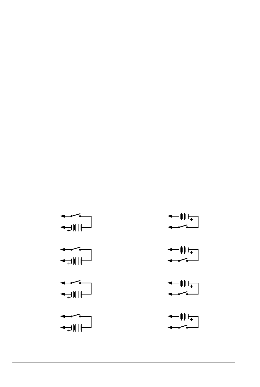
These four inputs are uncommitted optoisolators. Effectively,
you are sending the external control signal into a LED which has a
resistor wired in series. This requires external power be supplied
from somewhere. If the device you are controlling the input from
supplies power, then all is well. If you are wiring these inputs to
simple dry switch closures, you will need to ‘steal’ the power for
them from somewhere. Conveniently, there is the ‘power’ screw
terminals adjacent. You can pick up whatever power is being
used to run the Mp3-50/8 or Mp3-50/40 from these two screw
terminals.
‘A’, ‘B’, ‘C’ & ‘D’ Binary:
only.
The four optically isolated digital inputs can be used to se-
Firmware versions 1.07 and later
lect up to fifteen different shows directly with a binary weighted
pattern of bits. TO do this, you must set all four of these inputs
(both opening & closing edges) as ‘unused’ when you generate
your AutoDownload file from PC•MACs. The binary pattern is applied as follows:
21 of 119
Page 30
GILDERFLUKE & CO .• 205 SOUTH FLOWER STREET • BURBANK , CALIFORNIA 91502 • 818/840-9484 • 800/776-5972 • FAX 818/840-9485
AST COAST /FLORIDA O FFICE • 7041 GRAND NATIONAL D RIVE • SUITE 128d • ORLANDO , FL. 32819 • 407/354-5954 • FAX 407/354-5955
E
show # ‘A’ ‘B’ ‘C’ ‘D’ comment
0 off off off off not used (there is no show ‘0’)
1 on off off off
2 off on off off
3 on on off off
4 off off on off
5 on off on off
6 off on on off
7 onononoff
8 off off off on
9 on off off on
10 off on off on
11 on on off on
12 off off on on
13 on off on on
14 off on on on
15 on on on on
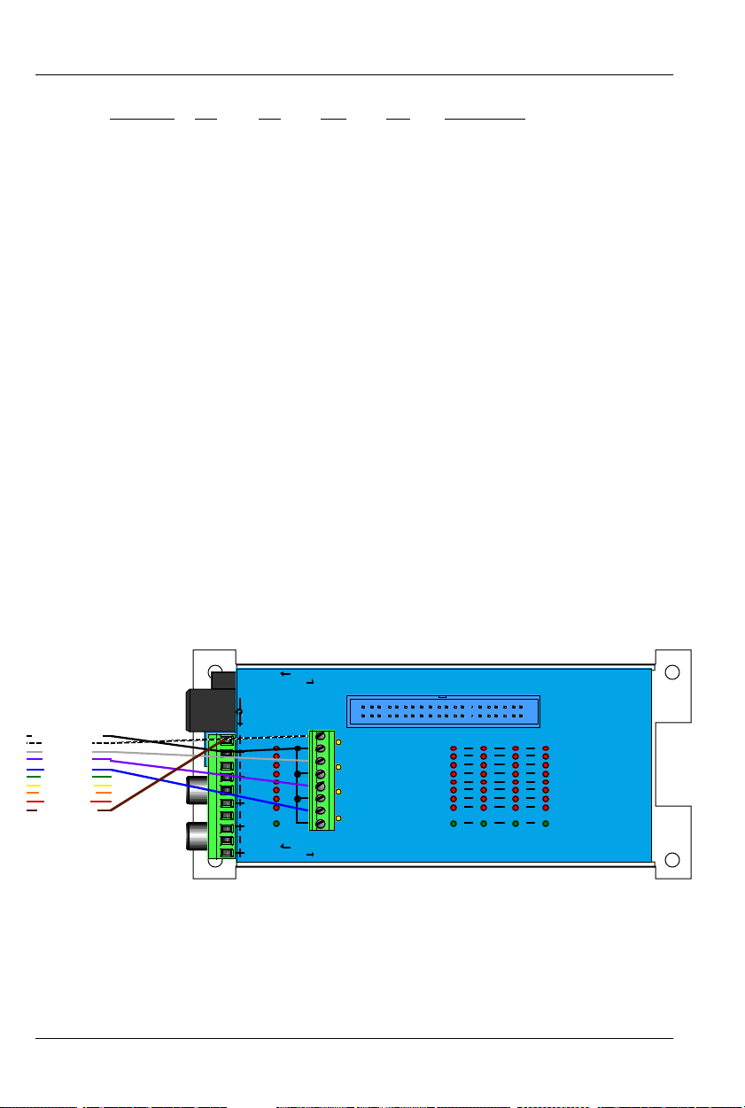
If you are using our KP-200 for selecting and playing shows, it
is wired as follows. The connection to the KP-200 is through a ten
position ribbon cable. Power for the KP-200 in this example is
being ‘borrowed’ from the Mp3-50/8 or Mp3-50/4. If you are
going to be running the cable from the KP-200 to the Mp3-50/8
or Mp3-50/40 a long distance, or if you are picking up audio ‘noise’ through this input, you can use a separate power supply to
completely isolate the KP-200 and the Mp3-50/8 or Mp3-50/40.
#10 Black (12-24 vdc)
#9 White (bit 0)
#8 Grey (bit 1)
#7 Violet (bit 2)
#6 Blue (bit 3)
#5 Green (bit 4)
#4 Yellow (bit 5)
#3 Orange (bit 6)
#2 Red (bit 7)
#1 Brown (ground)
ribbon cable to KP-200
be used to disable scans of the RTC schedules when the input is
opened. This can be used to stop sounds from playing automatically when they shouldn’t. Examples of where this feature can be
used are:
Trigger Power
internal
(switch on bottom)
external
9-24 vdc
Power
9-24 vdc
Power
In
Out
Left
Right
DMX/
MIDI
DMX/
MIDI
Speaker
Speaker
4
0
1
2
3
4
5
6
7
Fuse
4
isolated
RS-422
'A'
'B'
'C'
'D'
DMX/MIDI input
(switch on bottom)
3210
7
6
5
4
3
2
1
0
Fuse
3210
Gilderfluke & Company • Burbank, California
7
6
5
4
3
2
1
0
Fuse
MP3-50/40
If used with the ‘Atomic’ Clock option, the ‘C’/Blue input can
22 of 119
Page 31

GILDERFLUKE & CO .• 205 SOUTH FLOWER STREET • BURBANK , CALIFORNIA 91502 • 818/840-9484 • 800/776-5972 • FAX 818/840-9485
AST COAST /FLORIDA O FFICE • 7041 GRAND NATIONAL D RIVE • SUITE 128d • ORLANDO , FL. 32819 • 407/354-5954 • FAX 407/354-5955
E
a) In a church bell tower, where a simple switch opening can
be used to temporarily disable bells from ringing during a
service.
b) In a Theme Park, where this input can be tied to the existing
power management grid to disable tolling when the park is
closed.
c) If you have a show or sound which should not be interrupt-
ed by a scheduled event, or if schedule scans are causing
glitches in your show playback. You can set the show/sound
so that it ‘can not’ be stepped on, but if you have a particularly long schedule that must be scanned, it may cause a
hesitation in the show which is running. By using a show
control output wired into this input, you can control when
schedule scans can and can not take place during different parts of the show.
If used with the ‘Atomic’ Clock option, the ‘D’/White input is
what is used to resynchronize the RTC with the external ‘Atomic’
Clock. The time which has been entered in the Mp3 Configura-
tor must agree with the time set for the alarm on the ‘Atomic’
Clock module. In most cases, the reset time is set about a sec-
ond earlier than the ‘alarm’ time, to offset for the slight delays in
starting a Mp3 playback.
We are using 3:05:01 as the default resynchronization time.
The external ‘Atomic’ Clock MUST be set so that the alarm goes
off at 03:05:00. The extra second we are offsetting by is to allow
for the 1 second lag before a Mp3 SoundFile starts playing after it
is triggered. It is at 3:05 AM so that when daylight savings starts
and ends, there will be no more than one hour before the Mp3-
50/8 or Mp3-50/40 is resynchronized to the appropriate time. Any
earlier, and the daylight savings transition might be missed until
the next resynchronization time.
A single two conductor cable connects the ‘Atomic’ Clock
module to the Mp3-50/8 or Mp3-50/40. This wire lands on the
‘D’/White input to the Mp3-50/8 or Mp3-50/40 (the striped lead is
the positive, bottom most terminal). The input to the Mp3-50/8 or
Mp3-50/40 is optically isolated. If needed, you can stretch these
wires for hundreds of feet, if needed.
The link between the ‘Atomic’ Clock module and the Mp3-
50/8 or Mp3-50/40 can be tested by pressing the ‘snooze’ button
atop the ‘Atomic’ Clock. This will light the back light on the LCD
23 of 119
Page 32

GILDERFLUKE & CO .• 205 SOUTH FLOWER STREET • BURBANK , CALIFORNIA 91502 • 818/840-9484 • 800/776-5972 • FAX 818/840-9485
AST COAST /FLORIDA O FFICE • 7041 GRAND NATIONAL D RIVE • SUITE 128d • ORLANDO , FL. 32819 • 407/354-5954 • FAX 407/354-5955
E
display, as well as the LED indicator for the ‘D’/White input to the
Mp3-50/8 or Mp3-50/40. This will also set the RTC inside the Mp350/8 or Mp3-50/40 to the completely WRONG time, if the con-
nection is working. You must manually set the time within the
Mp3-50/8 or Mp3-50/40 after testing it in this way. If you don’t
want this to happen when testing this connection, power down
the Mp3-50/8 or Mp3-50/40 before doing this test. The LED will
light even with the Mp3-50/8 or Mp3-50/40 off. Power the Mp3-
50/8 or Mp3-50/40 back up when you are finished testing.
To permanently prevent such accidental clock 'miss' settings
after the ‘Atomic’ Clock is installed, you can open the battery
compartment and cut the wire which runs through it. This will disable the ‘snooze’ button, and thereby prevent it being hit accidentally in the future.
13) ‘J6’ Digital Outputs: Forty Position IDS Connector. Each Mp3-
50/40 has forty outputs. This connector is used for the first thirty-
two outputs. The last eight appear on the ‘1/4 J6’ connector on
the back of the Mp3-50/40.
These J6 Show Control outputs are just like the standard outputs used on all Gilderfluke & Company Show Control Systems.
Forty and ten position transition connectors are available for the
Mp3-50/8s or Mp3-50/40s to adapt the ribbon cables to screw
terminals.
The output connections for all Gilderfluke & Company Show
Control Systems are through ‘J-6’ output cables. These are forty
wire ribbon cables which are made up of four identical eight-bit
wide ‘channels’. A J-6 cable is often split up into four individual
channels. Each ‘1/4 J-6’ ribbon cable is made up of ten wires,
and can be used to control eight individual ‘digital’ (off/on) devices, or one eight-bit wide ‘analog’ device. Each group of ten
wires also includes a common power supply and ground wire.
To simplify wiring to any Gilderfluke animation system, the
connectors used on the 1/4 J-6 cables are what are called ‘insulation displacement’ (IDS) connectors. These simply snap on to an
entire cable, automatically ‘displacing’ the wire insulation and
making contact with the wires within. This means that an entire
ten wire cable can be terminated in seconds. All connectors are
polarized, to keep them from being plugged in backwards. Although there are tools made specifically for installing these connectors, the tool we find works best is a small bench vise.
24 of 119
Page 33

GILDERFLUKE & CO .• 205 SOUTH FLOWER STREET • BURBANK , CALIFORNIA 91502 • 818/840-9484 • 800/776-5972 • FAX 818/840-9485
AST COAST /FLORIDA O FFICE • 7041 GRAND NATIONAL D RIVE • SUITE 128d • ORLANDO , FL. 32819 • 407/354-5954 • FAX 407/354-5955
E
If attaching discrete wires from the J6 ribbon cable connector
presents a problem, we have forty and ten position transition connectors are available for the Mp3-50/8s or Mp3-50/40s to adapt
the ribbon cables to screw terminals. Ribbon cable to screw terminal adapters are also available from a number of different
sources.
Any eight digital devices or one eight-bit analog device can
be connected to any 1/4 J-6 cable as shown. The LED between
the ground (pin #1 brown) wire and supply (pin #10 black) wire
acts as an indicator that is lit if the fuse for that channel is OK.
All outputs are open collector switches to ground. Small flyback diodes are included in the outputs for driving inductive
loads. Larger inductive loads may require flyback diodes be installed directly across the loads. Power is supplied through a diode
and a solid state circuit breaker to the common pin(s) on the connector. A safe level of current is 150 milliamperes simultaneously
on each output. This is sufficient to drive most small relays, valves
and other similar loads directly. If fewer than eight outputs are on
at one time, then the outputs are rated as follows.
fuse
supply supply
flyback
diode
typical output typical input
The supply line for each 1/4 J-6 is PTC fused for 1 amp. You
should treat each 1/4 J-6 as an individual, and not cross the outputs or supply lines from one channel to the lines from any other
channel. Doing this won’t cause any damage, but can reduce
the protection for the outputs that the fuses normally provide.
The current Output Capacity of each output is as shown in
the following chart:
25 of 119
Page 34

y Cy
GILDERFLUKE & CO .• 205 SOUTH FLOWER STREET • BURBANK , CALIFORNIA 91502 • 818/840-9484 • 800/776-5972 • FAX 818/840-9485
AST COAST /FLORIDA O FFICE • 7041 GRAND NATIONAL D RIVE • SUITE 128d • ORLANDO , FL. 32819 • 407/354-5954 • FAX 407/354-5955
E
600ma.
500ma.
400ma.
300ma.
200ma.
Allowable Peak Collector Current @ 70ºC
100ma.
Peak Collector Current as a function
of Output Duty Cycle
2
3
4
5
6
7
8
Number of outputs
conducting
simultaneously
10% 20% 30% 40% 50% 60% 70% 80% 90%
Output Dut
cle
100%
26 of 119
Page 35

GILDERFLUKE & CO .• 205 SOUTH FLOWER STREET • BURBANK , CALIFORNIA 91502 • 818/840-9484 • 800/776-5972 • FAX 818/840-9485
AST COAST /FLORIDA O FFICE • 7041 GRAND NATIONAL D RIVE • SUITE 128d • ORLANDO , FL. 32819 • 407/354-5954 • FAX 407/354-5955
E
Each J-6 cable is arranged in the following order:
wire number color wire function
1 brown circuit ground
2 red channel 0 data bit 7
3 orange channel 0 data bit 6
4 yellow channel 0 data bit 5
5 green channel 0 data bit 4
6 blue channel 0 data bit 3
7 violet channel 0 data bit 2
8 gray channel 0 data bit 1
9 white channel 0 data bit 0
10 black + VDC unregulated power supply
11 brown circuit ground
12 red channel 1 data bit 7
13 orange channel 1 data bit 6
14 yellow channel 1 data bit 5
15 green channel 1 data bit 4
16 blue channel 1 data bit 3
17 violet channel 1 data bit 2
18 gray channel 1 data bit 1
19 white channel 1 data bit 0
20 black + VDC unregulated power supply
21 brown circuit ground
22 red channel 2 data bit 7
23 orange channel 2 data bit 6
24 yellow channel 2 data bit 5
25 green channel 2 data bit 4
26 blue channel 2 data bit 3
27 violet channel 2 data bit 2
28 gray channel 2 data bit 1
29 white channel 2 data bit 0
30 black + VDC unregulated power supply
31 brown circuit ground
32 red channel 3 data bit 7
33 orange channel 3 data bit 6
34 yellow channel 3 data bit 5
35 green channel 3 data bit 4
36 blue channel 3 data bit 3
37 violet channel 3 data bit 2
38 gray channel 3 data bit 1
39 white channel 3 data bit 0
40 black + VDC unregulated power supply
27 of 119
Page 36

GILDERFLUKE & CO .• 205 SOUTH FLOWER STREET • BURBANK , CALIFORNIA 91502 • 818/840-9484 • 800/776-5972 • FAX 818/840-9485
AST COAST /FLORIDA O FFICE • 7041 GRAND NATIONAL D RIVE • SUITE 128d • ORLANDO , FL. 32819 • 407/354-5954 • FAX 407/354-5955
E
Since it is unusual to have more than 50% of the outputs on
at any one time, you can usually assume the system has a 250
ma output current capacity per output. If you are going to be
turning on lots of heavy loads at the same time, you should derate this to 150 ma.. This is sufficient to drive the majority of loads
which will be directly connected to the outputs of the animation
system. If additional current capacity is needed, or if you need to
drive higher voltage loads, you can connect relays as needed to
the outputs of the animation system. Coincidentally, boards for
doing this are available from Gilderfluke & Company. These include:
DPDT relay board: A set of eight electromechanical relays with
double pole/double throw contacts rated at 5 amps each.
Reed relay board: A set of eight small electromechanical relays
with normally open contacts rated at 150 ma each.
I/O module: A set of eight small solid state relays with normally
open contacts rated at 3.5 amps each (alternating current
and direct current relays available).
Solid State Relay Fanning Strip: For connecting up to eight
popular ‘hockey puck’ style relays to a 1/4 J-6 output cable.
These are available with capacities of up to 75 amps each.
28 of 119
Page 37

GILDERFLUKE & CO .• 205 SOUTH FLOWER STREET • BURBANK , CALIFORNIA 91502 • 818/840-9484 • 800/776-5972 • FAX 818/840-9485
AST COAST /FLORIDA O FFICE • 7041 GRAND NATIONAL D RIVE • SUITE 128d • ORLANDO , FL. 32819 • 407/354-5954 • FAX 407/354-5955
E
Mp3-50/CC-10 Card Cage
The Mp3-50/CC-10 is a card cage designed to hold up to ten Mp3-
50s in 2U (3-1/2”) of standard 19” rack space. The Mp3-50/CC-10 can also
be used with Mp3-50/8 or Mp3-50/40, but there is no space between the
cards for the animation trigger inputs or Show Control Outputs (Mp3-50/40
only). In most cases, you will have to leave every slot adjacent to a Mp3-
50/8 or Mp3-50/40 vacant.
Once installed in a Mp3-50/CC-10, the DMX-512/MIDI serial ports on
Mp3-50/8 or Mp3-50/40 cards are all daisy chained together. These serial
ports can be used for DMX-512, networked serial, IR Triggers or MIDI input to
Mp3-50/8 or Mp3-50/40 cards. Mp3-50s do not include the DMX-512/MIDI
serial port.
Mp3-50, Mp3-50/8 or Mp3-50/40 cards are installed in a Mp3-50/CC10 by first removing the two screws which hold the connector card to the
end of the Mp3-50. The connector card at the end of the Mp3-50 is then
removed to be installed in the Mp3-50/CC-10.
29 of 119
Page 38

GILDERFLUKE & CO .• 205 SOUTH FLOWER STREET • BURBANK , CALIFORNIA 91502 • 818/840-9484 • 800/776-5972 • FAX 818/840-9485
AST COAST /FLORIDA O FFICE • 7041 GRAND NATIONAL D RIVE • SUITE 128d • ORLANDO , FL. 32819 • 407/354-5954 • FAX 407/354-5955
E
The same two screws which you removed are inserted through the
same holes through the connector card of the Mp3-50, but going the opposite direction. These two screws are then used to hold the connector
card into the Mp3-50/CC-10 (the cards and the screws are installed
through the front of the cage). As the connector card is plugged in to the
backplane, make sure that all twelve pins of J2 are inserted correctly into
the mating connector on the backplane of the Mp3-50/CC-10.
Now the Mp3-50, Mp3-50/8 or Mp3-50/40 can be plugged into the
card cage. Nothing else needs to be removed or changed on the Mp3-50,
Mp3-50/8 or Mp3-50/40 before they inserted into the Mp3-50/CC-10.
Power can be wired into any of the card cage positions, or through the
heavy current screw terminals. The latter should be used if you are using
the amplifiers or Show Control outputs on Mp3-50/8 or Mp3-50/40 cards.
This is because the total current draw can exceed the capacity of the 2.1
mm power connector or smaller screw terminals located on the back of
each Mp3-50.
The DMX-512/MIDI serial port is daisy chained from higher numbered
30 of 119
Page 39

GILDERFLUKE & CO .• 205 SOUTH FLOWER STREET • BURBANK , CALIFORNIA 91502 • 818/840-9484 • 800/776-5972 • FAX 818/840-9485
AST COAST /FLORIDA O FFICE • 7041 GRAND NATIONAL D RIVE • SUITE 128d • ORLANDO , FL. 32819 • 407/354-5954 • FAX 407/354-5955
E
slots towards lower number slots. If a single slot is left unpopulated, or populated with a Mp3-50, will break the daisy chain. This can be used to divide
the backplane into two or more universes.
If you are daisy chaining MIDI, run the MIDI signal into the highest numbered populated slot in the Mp3-50/CC-10. This card MUST be set for an
optoisolated, current loop input. All of the consecutive cards downstream
of the first card should be set for RS-422 operation.
If you are daisy chaining DMX-512 or networked serial commands, all of
the cards should be set for RS-422 operation. Again, the signal is wired into
the highest numbered populated slot and will be daisy chained through all
of the adjacent lower numbered slots.
An Mp3-50, Mp3-50/8 or Mp3-50/40 can be converted back to standalone use by simply reversing the installation process. Remove the two
screws which hold the connector card into the Mp3-50/CC-10, Plug it back
into the Mp3-50, Mp3-50/8 or Mp3-50/40, and secure it with the two
screws.
31 of 119
Page 40

GILDERFLUKE & CO .• 205 SOUTH FLOWER STREET • BURBANK , CALIFORNIA 91502 • 818/840-9484 • 800/776-5972 • FAX 818/840-9485
AST COAST /FLORIDA O FFICE • 7041 GRAND NATIONAL D RIVE • SUITE 128d • ORLANDO , FL. 32819 • 407/354-5954 • FAX 407/354-5955
E
PC•MACs Shows for Mp3-50/8
This section gives some hints for setting up the shows that will be used
by the Show Control side of a Mp3-50/8. There are literally thousands of
possible configuration arrangements. Most applications will use one of the
following configurations. The most common configuration is the ‘b’ option.
The ‘Show Capacities’ shown is at 30 frames (updates) per second.
Mp3-50/8: 1st MPU DMX- Vol. Vol. Show
# description Anim. Control 512 Right Left Capacity
a 8 digitals/MPU 0 x x x x 5 Hours
b 8 digitals, 8 MPU 0 1 x x x 2.5 hours
c 8 digitals, 8 MPU, 1 volume 0 1 x 2 2 97 min.
d 8 digitals, 8 MPU, 2 volume 0 1 x 2 3 72 min.
e 8 digitals, 8 MPU, DMX-512 0 1 2 x x 18-97 min.
f 8 digitals, 8 MPU, 16 DMX 16 17 0 x x 16 min.
Mp3-50/8 Show Configurations: The Mp3-50/8 has eight Show Control
outputs on one eight bit wide channel. Additional channels you may
choose to use are the MPU Trigger channel (so you don’t have to loose any
digital outputs for triggering the Mp3 Player), RealTime Audio Level Control
Channels, and DMX-512 output channels.
In all but the first of the following examples, the eight digitals can be
used as one analog channel. The Show Control outputs will need to be fed
through a Digital to Analog Converter (DAC-08) to convert the digital channels to a single analog voltage output.
a) Mp3-50/8 with One Combined Show Control/Mp3 Control
Channel: At a minimum, all you would need to program is the
one eight bit wide Show Control output channel. This would mean
that you would have to give up some number of your digital out-
puts to use for triggering the Mp3 Player. The Mp3 Player is con-
figured for triggering AudioFile starts on the normal 1/4 J6 inputs.
This configuration gives you a show capacity of approximately
five hours in the onboard Flash memory.
Starting with a blank site file, you can create all the channels
you need by:
1) Open PC•MACs, Create a 'New' show. Go to 'Channels
Pulldown'/'Create Multiple Channels....'.
2) Select eight digital and zero analog channels. The first eight
outputs (on channel ‘0’) will go to the Show Control Outputs. These will be used for both Show Control and trigger-
32 of 119
Page 41

GILDERFLUKE & CO .• 205 SOUTH FLOWER STREET • BURBANK , CALIFORNIA 91502 • 818/840-9484 • 800/776-5972 • FAX 818/840-9485
AST COAST /FLORIDA O FFICE • 7041 GRAND NATIONAL D RIVE • SUITE 128d • ORLANDO , FL. 32819 • 407/354-5954 • FAX 407/354-5955
E
ing the Mp3 Player.
3) Click ‘OK’ to create these channels.
When you have finished programming your show you will
AutoDownload it to the Mp3-50/8. Set the ‘First Channel’ to ‘0’
and the ‘Last Channel’ to ‘0’ on the PC•MACs File Pulldown/Save
as AutoDownload.... window.
In the Mp3 Configurator Program:
1) Track Setup Tab: Point it at your SmartMedia card and set as
needed.
2) PlayLists Tab: Set up as needed, if needed.
3) Audio Tab: Set audio levels and EQ as needed. Disable Re-
alTime Audio Level Control. Enable/Disable amplifier as
needed.
4) Input Tab: You will be overlapping this input channel with
the Show Control outputs of the Mp3-50/8. Set up some of
the inputs to select and start AudioFiles, as needed. Don’t
forget to save a few outputs for the Show control!
5) MPU Input Tab: You will be using the Optoisolated inputs in
this case. Disable ALL of the MPU Inputs.
6) Serial Control Tab: The Brick Address is usually set at '0', u n-
less you will be accessing the card using Net Serial com-
mands. The Repeater Control Channel is unused, so it can
be set anywhere. First animation Channel Number must be
set to '0'. Disable/Enable Net Serial and IR Trigger modes if
needed (these are
usually
disabled)
7) DMX-512 Control Tab: Enable DMX-512 Control, unless you
are using MIDI, Net Serial or IR Trigger Modes. Enable DMX-
512 checksums if you will be feeding DMX-512 from any
Gilderfluke & Company products (
usually
enabled). The Repeater Control Channel and First Animation channel number were set on a previous tab.
8) MIDI Control Tab: Disable MIDI, unless you plan to use it.
Disable MIDI Notes Trigger Animation Playback, unless you
plan to use it. Set MIDI Channel Number and Animation First
Note number if you will be using MIDI, otherwise, ignore
them.
9) Flash Setup Tab: Enable Animation from Flash, unless you
will never be using the onboard show storage.
33 of 119
Page 42

GILDERFLUKE & CO .• 205 SOUTH FLOWER STREET • BURBANK , CALIFORNIA 91502 • 818/840-9484 • 800/776-5972 • FAX 818/840-9485
AST COAST /FLORIDA O FFICE • 7041 GRAND NATIONAL D RIVE • SUITE 128d • ORLANDO , FL. 32819 • 407/354-5954 • FAX 407/354-5955
E
Enable/Disable outputs when stopped, as needed. Leave
the Write Protect Flash unchecked, or you will not be able to
save the show you are creating to the Mp3-50/8 or Mp3-
50/40. Disable it after you have completed programming, if
needed. The Repeater Control Channel and First Animation
channel number were set on a previous tab.
b) Mp3-50/8 with One Show Control, One Mp3 Control Channel:
The most typical installation for a Mp3-50/8 uses one eight bit
channel for Show Control, and a second one for controlling the
Mp3 playback. This means that none of the Show Control outputs
are ‘lost’ to the Mp3 Player. The Mp3 Player is configured for triggering AudioFile starts on the MPU input bits.
This configuration gives you a show capacity of approximately
2-1/2 hours in the onboard Flash memory.
Starting with a blank site file, you can create all the channels
you need by:
1) Open PC•MACs, Create a 'New' show. Go to 'Channels
Pulldown'/'Create Multiple Channels....'.
2) Select sixteen digital and zero analog channels. The first
eight outputs (on channel ‘0’) will go to the Show Control
Outputs. The last eight outputs (on channel ‘1’) will be used
for triggering the Mp3 Player.
3) Click ‘OK’ to create these channels.
When you have finished programming your show you will
AutoDownload it to the Mp3-50/8. Set the ‘First Channel’ to ‘0’
and the ‘Last Channel’ to ‘1’ on the PC•MACs File Pulldown/Save
as AutoDownload.... window.
In the Mp3 Configurator Program:
1) Track Setup Tab: Point it at your SmartMedia card and set as
needed.
2) PlayLists Tab: Set up as needed, if needed.
3) Audio Tab: Set audio levels and EQ as needed. Disable Re-
alTime Audio Level Control. Enable/Disable amplifier as
needed.
4) Input Tab: You will be using the MPU inputs in this case. Disable ALL of the Optoisolated Inputs.
34 of 119
Page 43

GILDERFLUKE & CO .• 205 SOUTH FLOWER STREET • BURBANK , CALIFORNIA 91502 • 818/840-9484 • 800/776-5972 • FAX 818/840-9485
AST COAST /FLORIDA O FFICE • 7041 GRAND NATIONAL D RIVE • SUITE 128d • ORLANDO , FL. 32819 • 407/354-5954 • FAX 407/354-5955
E
5) MPU Input Tab: Set up the inputs to select and start Au-
dioFiles and ramp audio levels, as needed.
6) Serial Control Tab: The Brick Address is usually set at '0', u n-
less you will be accessing the card using Net Serial commands. The Repeater Control Channel must be set to '1'.
First animation Channel Number must be set to '0'.
Disable/Enable Net Serial and IR Trigger modes as needed
(these are
usually
disabled)
7) DMX-512 Control Tab: Enable DMX-512 Control, unless you
are using MIDI, Net Serial or IR Trigger Modes. Enable DMX512 checksums if you will be feeding DMX-512 from any
Gilderfluke & Company products (
usually
enabled). The Repeater Control Channel and First Animation channel number were set on a previous tab.
8) MIDI Control Tab: Disable MIDI, unless you plan to use it.
Disable MIDI Notes Trigger Animation Playback, unless you
plan to use it. Set MIDI Channel Number and Animation First
Note number if you will be using MIDI, otherwise, ignore
them.
9) Flash Setup Tab: Enable Animation from Flash, unless you
will never be using the onboard show storage.
Enable/Disable outputs when stopped, as needed. Leave
the Write Protect Flash unchecked, or you will not be able to
save the show you are creating to the Mp3-50/8 or Mp3-
50/40. Disable it after you have completed programming, if
needed. The Repeater Control Channel and First Animation
channel number were set on a previous tab.
c) Mp3-50/8 with One Audio Level Control Channel: This configu-
ration adds a single analog channel which can be used to control the audio level of the Mp3 Player as a part of the show con-
trol file.
This configuration gives you a show capacity of approximately
97 minutes in the onboard Flash memory.
Starting with a blank site file, you can create all the channels
you need by:
1) Open PC•MACs, Create a 'New' show. Go to 'Channels
Pulldown'/'Create Multiple Channels....'.
2) Select sixteen digital and zero analog channels. The first
eight outputs (on channel ‘0’) will go to the Show Control
35 of 119
Page 44

GILDERFLUKE & CO .• 205 SOUTH FLOWER STREET • BURBANK , CALIFORNIA 91502 • 818/840-9484 • 800/776-5972 • FAX 818/840-9485
AST COAST /FLORIDA O FFICE • 7041 GRAND NATIONAL D RIVE • SUITE 128d • ORLANDO , FL. 32819 • 407/354-5954 • FAX 407/354-5955
E
Outputs. The last eight outputs (on channel ‘1’) will be used
for triggering the Mp3 Player.
3) Click ‘OK’ to create these channels.
4) Go to PC•MACs 'Channels Pulldown'/'Create Multiple Chan-
nels....'.
5) Select zero digital and one 8 bit analog channel. This will be
your audio level control channel at address ‘2’.
6) Click ‘OK’ to create this channel.
When you have finished programming your show you will
AutoDownload it to the Mp3-50/8. Set the ‘First Channel’ to ‘0’
and the ‘Last Channel’ to ‘2’ on the PC•MACs File Pulldown/Save
as AutoDownload.... window.
In the Mp3 Configurator Program:
1) Track Setup Tab: Point it at your SmartMedia card and set as
needed.
2) PlayLists Tab: Set up as needed, if needed.
3) Audio Tab: Set audio levels and EQ as needed. Enable Real-
Time Audio Level Control. You can control one or both outputs from the analog channel you have created. Set the
addresses of the Level Control Channels to ‘2’.
Enable/Disable amplifier as needed.
4) Input Tab: You will be using the MPU inputs in this case. Disable ALL of the Optoisolated Inputs.
5) MPU Input Tab: Set up the inputs to select and start AudioFiles and ramp audio levels, as needed.
6) Serial Control Tab: The Brick Address is usually set at '0', u nless you will be accessing the card using Net Serial commands. The Repeater Control Channel must be set to '1'.
First animation Channel Number must be set to '0'.
Disable/Enable Net Serial and IR Trigger modes as needed
(these are
usually
disabled)
7) DMX-512 Control Tab: Enable DMX-512 Control, unless you
are using MIDI, Net Serial or IR Trigger Modes. Enable DMX512 checksums if you will be feeding DMX-512 from any
Gilderfluke & Company products (
usually
enabled). The Repeater Control Channel and First Animation channel number were set on a previous tab.
36 of 119
Page 45

GILDERFLUKE & CO .• 205 SOUTH FLOWER STREET • BURBANK , CALIFORNIA 91502 • 818/840-9484 • 800/776-5972 • FAX 818/840-9485
AST COAST /FLORIDA O FFICE • 7041 GRAND NATIONAL D RIVE • SUITE 128d • ORLANDO , FL. 32819 • 407/354-5954 • FAX 407/354-5955
E
8) MIDI Control Tab: Disable MIDI, unless you plan to use it.
Disable MIDI Notes Trigger Animation Playback, unless you
plan to use it. Set MIDI Channel Number and Animation First
Note number if you will be using MIDI, otherwise, ignore
them.
9) Flash Setup Tab: Enable Animation from Flash, unless you
will never be using the onboard show storage.
Enable/Disable outputs when stopped, as needed. Leave
the Write Protect Flash unchecked, or you will not be able to
save the show you are creating to the Mp3-50/8 or Mp3-
50/40. Disable it after you have completed programming, if
needed. The Repeater Control Channel and First Animation
channel number were set on a previous tab.
d) Mp3-50/8 with Two Audio Level Control Channels: This configu-
ration adds two analog channels which can be used to independently control the left and right audio levels of the Mp3 Player as
a part of the show control file.
This configuration gives you a show capacity of approximately
72 minutes in the onboard Flash memory.
Starting with a blank site file, you can create all the channels
you need by:
1) Open PC•MACs, Create a 'New' show. Go to 'Channels
Pulldown'/'Create Multiple Channels....'.
2) Select sixteen digital and zero analog channels. The first
eight outputs (on channel ‘0’) will go to the Show Control
Outputs. The last eight outputs (on channel ‘1’) will be used
for triggering the Mp3 Player.
3) Click ‘OK’ to create these channels.
4) Go to PC•MACs 'Channels Pulldown'/'Create Multiple Chan-
nels....'.
5) Select zero digital and two, 8 bit analog channel. These will
be your audio level control channels at addresses ‘2’ and
‘3’.
6) Click ‘OK’ to create these channels.
When you have finished programming your show you will
AutoDownload it to the Mp3-50/8. Set the ‘First Channel’ to ‘0’
and the ‘Last Channel’ to ‘3’ on the PC•MACs File Pulldown/Save
37 of 119
Page 46

GILDERFLUKE & CO .• 205 SOUTH FLOWER STREET • BURBANK , CALIFORNIA 91502 • 818/840-9484 • 800/776-5972 • FAX 818/840-9485
AST COAST /FLORIDA O FFICE • 7041 GRAND NATIONAL D RIVE • SUITE 128d • ORLANDO , FL. 32819 • 407/354-5954 • FAX 407/354-5955
E
as AutoDownload.... window.
In the Mp3 Configurator Program:
1) Track Setup Tab: Point it at your SmartMedia card and set as
needed.
2) PlayLists Tab: Set up as needed, if needed.
3) Audio Tab: Set audio levels and EQ as needed. Enable Real-
Time Audio Level Control. Each audio output has its own
analog channel to control it. Set the addresses of the Level
Control Channels to ‘2’ and ‘3’. Enable/Disable amplifier as
needed.
4) Input Tab: You will be using the MPU inputs in this case. Disable ALL of the Optoisolated Inputs.
5) MPU Input Tab: Set up the inputs to select and start AudioFiles and ramp audio levels, as needed.
6) Serial Control Tab: The Brick Address is usually set at '0', u nless you will be accessing the card using Net Serial commands. The Repeater Control Channel must be set to '1'.
First animation Channel Number must be set to '0'.
Disable/Enable Net Serial and IR Trigger modes as needed
(these are
usually
disabled)
7) DMX-512 Control Tab: Enable DMX-512 Control, unless you
are using MIDI, Net Serial or IR Trigger Modes. Enable DMX512 checksums if you will be feeding DMX-512 from any
Gilderfluke & Company products (
usually
enabled). The Repeater Control Channel and First Animation channel number were set on a previous tab.
8) MIDI Control Tab: Disable MIDI, unless you plan to use it.
Disable MIDI Notes Trigger Animation Playback, unless you
plan to use it. Set MIDI Channel Number and Animation First
Note number if you will be using MIDI, otherwise, ignore
them.
9) Flash Setup Tab: Enable Animation from Flash, unless you
will never be using the onboard show storage.
Enable/Disable outputs when stopped, as needed. Leave
the Write Protect Flash unchecked, or you will not be able to
save the show you are creating to the Mp3-50/8 or Mp3-
50/40. Disable it after you have completed programming, if
needed. The Repeater Control Channel and First Animation
channel number were set on a previous tab.
38 of 119
Page 47

GILDERFLUKE & CO .• 205 SOUTH FLOWER STREET • BURBANK , CALIFORNIA 91502 • 818/840-9484 • 800/776-5972 • FAX 818/840-9485
AST COAST /FLORIDA O FFICE • 7041 GRAND NATIONAL D RIVE • SUITE 128d • ORLANDO , FL. 32819 • 407/354-5954 • FAX 407/354-5955
E
e) Mp3-50/8 with DMX-512 w/Overlapping Channels: This configu-
ration goes back to the typical installation (‘b’ above) and adds
one or more channels of DMX-512 output. If you are using Serial
RealTime Update mode during programming, this is the only configuration which will allow you to access ALL of the Show control
and DMX-512 channels through the serial port.
The DMX-512 transmission always starts with the first channel
stored in the Flash memory, and transmits the first sixteen consecutive channels. The two channels of Show Control (one for the
digital outputs and one for the MPU control) are sent out through
the first two channels of DMX-512 (you probably don’t want to put
a dimmer on these channels). This leaves somewhere between
one and fourteen channels of DMX-512 output for lighting, moving lights, or whatever.
Depending on the number of DMX channels you need, this
configuration gives a capacity of between 97 and 18 minutes in
the onboard Flash memory.
Starting with a blank site file, you can create all the channels
you need by:
1) Open PC•MACs, Create a 'New' show. Go to 'Channels
Pulldown'/'Create Multiple Channels....'.
2) Select sixteen digital and zero analog channels. The first
eight outputs (on channel ‘0’) will go to the Show Control
Outputs. The last eight outputs (on channel ‘1’) will be used
for triggering the Mp3 Player.
3) Click ‘OK’ to create these channels.
4) Go to PC•MACs 'Channels Pulldown'/'Create Multiple Chan-
nels....'.
5) Select zero digital and between one and fourteen, 8 bit
analog channels. These will be your DMX-512 channels
starting at address ‘2’ and going to a maximum of ‘15’.
6) Click ‘OK’ to create these channels.
When you have finished programming your show you will
AutoDownload it to the Mp3-50/8. Set the ‘First Channel’ to ‘0’
and the ‘Last Channel’ to between ‘2’ and ‘15’ on the PC•MACs
File Pulldown/Save as AutoDownload.... window.
In the Mp3 Configurator Program:
1) Track Setup Tab: Point it at your SmartMedia card and set as
39 of 119
Page 48

GILDERFLUKE & CO .• 205 SOUTH FLOWER STREET • BURBANK , CALIFORNIA 91502 • 818/840-9484 • 800/776-5972 • FAX 818/840-9485
AST COAST /FLORIDA O FFICE • 7041 GRAND NATIONAL D RIVE • SUITE 128d • ORLANDO , FL. 32819 • 407/354-5954 • FAX 407/354-5955
E
needed.
2) PlayLists Tab: Set up as needed, if needed.
3) Audio Tab: Set audio levels and EQ as needed. Disable Re-
alTime Audio Level Control. Enable/Disable amplifier as
needed.
4) Input Tab: You will be using the MPU inputs in this case. Disable ALL of the Optoisolated Inputs.
5) MPU Input Tab: Set up the inputs to select and start AudioFiles and ramp audio levels, as needed.
6) Serial Control Tab: The Brick Address is usually set at '0', u nless you will be accessing the card using Net Serial commands. The Repeater Control Channel must be set to '1'.
First Animation Channel Number must be set to '0'. Disable
Net Serial and IR Trigger modes.
7) DMX-512 Control Tab: Disable DMX-512 Control. The Repeater Control Channel and First Animation channel number were set on a previous tab.
8) MIDI Control Tab: Disable MIDI and MIDI Notes Trigger Animation Playback. Disregard MIDI Channel Number and Animation First Note number.
9) Flash Setup Tab: Enable Animation from Flash, unless you
will never be using the onboard show storage.
Enable/Disable outputs when stopped, as needed. Leave
the Write Protect Flash unchecked, or you will not be able to
save the show you are creating to the Mp3-50/8 or Mp3-
50/40. Disable it after you have completed programming, if
needed. The Repeater Control Channel and First Animation
channel number were set on a previous tab.
f) Mp3-50/8 with Sixteen DMX-512 Channels: This configuration
goes back to the typical installation (‘b’ above) and adds sixteen
channels of DMX-512 output. If you are using Serial RealTime Update mode during programming, you will only be able to access
the DMX-512 channels through the serial port. The show control
ports are located above sixteen channels, so they will not be updated in RealTime.
The DMX-512 transmission always starts with the first channel
stored in the Flash memory, and transmits the first sixteen consecutive channels. This is where the DMX-512 data will live.
40 of 119
Page 49

GILDERFLUKE & CO .• 205 SOUTH FLOWER STREET • BURBANK , CALIFORNIA 91502 • 818/840-9484 • 800/776-5972 • FAX 818/840-9485
AST COAST /FLORIDA O FFICE • 7041 GRAND NATIONAL D RIVE • SUITE 128d • ORLANDO , FL. 32819 • 407/354-5954 • FAX 407/354-5955
E
This configuration consumes eighteen channels of Flash. This
gives a capacity of 16 minutes in the onboard Flash memory.
Starting with a blank site file, you can create all the channels
you need by:
1) Open PC•MACs, Create a 'New' show. Go to 'Channels
Pulldown'/'Create Multiple Channels....'.
2) Select sixteen digital and sixteen analog channels. The six-
teen analog channels which will be sent tout through the
DMX-512 output are located at channels ‘0’ through ‘15’.
The first eight digital outputs (on channel ‘16’) will go to the
Show Control Outputs. The last eight outputs (on channel
‘17’) will be used for triggering the Mp3 Player.
3) Click ‘OK’ to create these channels.
When you have finished programming your show you will
AutoDownload it to the Mp3-50/8. Set the ‘First Channel’ to ‘0’
and the ‘Last Channel’ to ‘17’ on the PC•MACs File Pulldown/Save
as AutoDownload.... window.
In the Mp3 Configurator Program:
1) Track Setup Tab: Point it at your SmartMedia card and set as
needed.
2) PlayLists Tab: Set up as needed, if needed.
3) Audio Tab: Set audio levels and EQ as needed. Disable Re-
alTime Audio Level Control. Enable/Disable amplifier as
needed.
4) Input Tab: You will be using the MPU inputs in this case. Dis-
able ALL of the Optoisolated Inputs.
5) MPU Input Tab: Set up the inputs to select and start Au-
dioFiles and ramp audio levels, as needed.
6) Serial Control Tab: The Brick Address is usually set at '0', u n-
less you will be accessing the card using Net Serial com-
mands. The Repeater Control Channel must be set to ‘17’.
First Animation Channel Number must be set to ‘16’. Disable
Net Serial and IR Trigger modes.
7) DMX-512 Control Tab: Disable DMX-512 Control. The Re-
peater Control Channel and First Animation channel num-
ber were set on a previous tab.
8) MIDI Control Tab: Disable MIDI and MIDI Notes Trigger Ani-
41 of 119
Page 50

GILDERFLUKE & CO .• 205 SOUTH FLOWER STREET • BURBANK , CALIFORNIA 91502 • 818/840-9484 • 800/776-5972 • FAX 818/840-9485
AST COAST /FLORIDA O FFICE • 7041 GRAND NATIONAL D RIVE • SUITE 128d • ORLANDO , FL. 32819 • 407/354-5954 • FAX 407/354-5955
E
mation Playback. Disregard MIDI Channel Number and Animation First Note number.
9) Flash Setup Tab: Enable Animation from Flash, unless you
will never be using the onboard show storage.
Enable/Disable outputs when stopped, as needed. Leave
the Write Protect Flash unchecked, or you will not be able to
save the show you are creating to the Mp3-50/8 or Mp3-
50/40. Disable it after you have completed programming, if
needed. The Repeater Control Channel and First Animation
channel number were set on a previous tab.
42 of 119
Page 51

GILDERFLUKE & CO .• 205 SOUTH FLOWER STREET • BURBANK , CALIFORNIA 91502 • 818/840-9484 • 800/776-5972 • FAX 818/840-9485
AST COAST /FLORIDA O FFICE • 7041 GRAND NATIONAL D RIVE • SUITE 128d • ORLANDO , FL. 32819 • 407/354-5954 • FAX 407/354-5955
E
PC•MACs Shows for Mp3-50/40
This section gives some hints for setting up the shows that will be used
by the Show Control side of a Mp3-50/40. There are literally thousands of
possible configuration arrangements. Most applications will use one of the
following configurations. The most common configuration is the ‘b’ option.
The ‘Show Capacities’ shown is at 30 frames (updates) per second.
Mp3-50/40: 1st MPU DMX- Vol. Vol. Show
# description Anim. Control 512 Right Left Capacity
a 40 digitals/MPU 0 4 x x x 1 Hour
b 40 digitals, 8 MPU 0 5 x x x 48 min.
c 40 digitals, 8 MPU, 1 volume 0 5 x 6 6 41 min.
d 40 digitals, 8 MPU, 2 volume 0 5 x 6 7 36 min.
e 40 digitals, 8 MPU, DMX-512 0 5 6 x x 18-41 min.
f 40 digitals, 8 MPU, 16 DMX 16 17 0 x x 13 min.
Mp3-50/40 Show Configurations: The Mp3-50/40 has forty Show Con-
trol outputs on five eight bit wide channel. Additional channels you may
choose to use are the MPU Trigger channel (so you don’t have to loose any
digital outputs for triggering the Mp3 Player), RealTime Audio Level Control
Channels, and DMX-512 output channels.
The forty Show Control outputs are normally used for digital outputs on
the Mp3-50/40. Using an external Digital to Analog converter (DAC-08 or
DAC-Quad), one or more of the analog channels can be used for analog
functions. In the following descriptions, you are creating forty digital outputs
for use on the forty digital Show Control outputs. The digitals can be combined with analog functions in any of the following combinations:
1 analog and 32 digitals
2 analogs and 24 digitals
3 analogs and 16 digitals
4 analogs and 8 digitals
5 analogs and 0 digitals
a) Mp3-50/40 with One Combined Show Control/Mp3 Control
Channel: At a minimum, all you would need to program is five
eight bit wide Show Control output channels. This would mean
that you would have to give up some number of your last channel’s digital outputs to use for triggering the Mp3 Player. The Mp3
Player is configured for triggering AudioFile starts on the normal
1/4 J6 inputs.
This configuration gives you a show capacity of approximately
one hour in the onboard Flash memory.
43 of 119
Page 52

GILDERFLUKE & CO .• 205 SOUTH FLOWER STREET • BURBANK , CALIFORNIA 91502 • 818/840-9484 • 800/776-5972 • FAX 818/840-9485
AST COAST /FLORIDA O FFICE • 7041 GRAND NATIONAL D RIVE • SUITE 128d • ORLANDO , FL. 32819 • 407/354-5954 • FAX 407/354-5955
E
Starting with a blank site file, you can create all the channels
you need by:
1) Open PC•MACs, Create a 'New' show. Go to 'Channels
Pulldown'/'Create Multiple Channels....'.
2) Select forty digital and zero analog channels. The digitals
that come out of the J6 connector are addressed from ‘0’
through ‘3’. The digitals that will come out of the 1/4 J6 are
addressed at ‘4’.
3) Click ‘OK’ to create these channels.
When you have finished programming your show you will
AutoDownload it to the Mp3-50/8. Set the ‘First Channel’ to ‘0’
and the ‘Last Channel’ to ‘4’ on the PC•MACs File Pulldown/Save
as AutoDownload.... window.
In the Mp3 Configurator Program:
1) Track Setup Tab: Point it at your SmartMedia card and set as
needed.
2) PlayLists Tab: Set up as needed, if needed.
3) Audio Tab: Set audio levels and EQ as needed. Disable Re-
alTime Audio Level Control. Enable/Disable amplifier as
needed.
4) Input Tab: You will be overlapping this input channel with
the Show Control outputs of the Mp3-50/8. Set up some of
the inputs to select and start AudioFiles, as needed. Don’t
forget to save a few outputs for the Show control!
5) MPU Input Tab: You will be using the Optoisolated inputs in
this case. Disable ALL of the MPU Inputs.
6) Serial Control Tab: The Brick Address is usually set at '0', u nless you will be accessing the card using Net Serial commands. The Repeater Control Channel is unused, so it can
be set anywhere. First animation Channel Number must be
set to '0'. Disable/Enable Net Serial and IR Trigger modes if
needed (these are
usually
disabled)
7) DMX-512 Control Tab: Enable DMX-512 Control, unless you
are using MIDI, Net Serial or IR Trigger Modes. Enable DMX512 checksums if you will be feeding DMX-512 from any
Gilderfluke & Company products (
usually
enabled). The Repeater Control Channel and First Animation channel number were set on a previous tab.
44 of 119
Page 53

GILDERFLUKE & CO .• 205 SOUTH FLOWER STREET • BURBANK , CALIFORNIA 91502 • 818/840-9484 • 800/776-5972 • FAX 818/840-9485
AST COAST /FLORIDA O FFICE • 7041 GRAND NATIONAL D RIVE • SUITE 128d • ORLANDO , FL. 32819 • 407/354-5954 • FAX 407/354-5955
E
8) MIDI Control Tab: Disable MIDI, unless you plan to use it.
Disable MIDI Notes Trigger Animation Playback, unless you
plan to use it. Set MIDI Channel Number and Animation First
Note number if you will be using MIDI, otherwise, ignore
them.
9) Flash Setup Tab: Enable Animation from Flash, unless you
will never be using the onboard show storage.
Enable/Disable outputs when stopped, as needed. Leave
the Write Protect Flash unchecked, or you will not be able to
save the show you are creating to the Mp3-50/8 or Mp3-
50/40. Disable it after you have completed programming, if
needed. The Repeater Control Channel and First Animation
channel number were set on a previous tab.
b) Mp3-50/40 with Five Show Control, One Mp3 Control Channel:
The most typical installation for a Mp3-50/8 uses five eight bit
channel for Show Control, and a final channel for controlling the
Mp3 playback. This means that none of the Show Control outputs
are ‘lost’ to the Mp3 Player. The Mp3 Player is configured for triggering AudioFile starts on the MPU input bits.
This configuration gives you a show capacity of approximately
48 minutes in the onboard Flash memory.
Starting with a blank site file, you can create all the channels
you need by:
1) Open PC•MACs, Create a 'New' show. Go to 'Channels
Pulldown'/'Create Multiple Channels....'.
2) Select forty-eight digital and zero analog channels. The digi-
tals that come out of the J6 connector are addressed from
‘0’ through ‘3’. The digitals that will come out of the 1/4 J6
are addressed at ‘4’. The last eight outputs (on address ‘5’)
will be used for triggering the Mp3 Player.
3) Click ‘OK’ to create these channels.
When you have finished programming your show you will
AutoDownload it to the Mp3-50/8. Set the ‘First Channel’ to ‘0’
and the ‘Last Channel’ to ‘5’ on the PC•MACs File Pulldown/Save
as AutoDownload.... window.
In the Mp3 Configurator Program:
1) Track Setup Tab: Point it at your SmartMedia card and set as
needed.
45 of 119
Page 54

GILDERFLUKE & CO .• 205 SOUTH FLOWER STREET • BURBANK , CALIFORNIA 91502 • 818/840-9484 • 800/776-5972 • FAX 818/840-9485
AST COAST /FLORIDA O FFICE • 7041 GRAND NATIONAL D RIVE • SUITE 128d • ORLANDO , FL. 32819 • 407/354-5954 • FAX 407/354-5955
E
2) PlayLists Tab: Set up as needed, if needed.
3) Audio Tab: Set audio levels and EQ as needed. Disable Re-
alTime Audio Level Control. Enable/Disable amplifier as
needed.
4) Input Tab: You will be using the MPU inputs in this case. Disable ALL of the Optoisolated Inputs.
5) MPU Input Tab: Set up the inputs to select and start AudioFiles and ramp audio levels, as needed.
6) Serial Control Tab: The Brick Address is usually set at '0', u nless you will be accessing the card using Net Serial commands. The Repeater Control Channel must be set to ‘5’.
First animation Channel Number must be set to '0'.
Disable/Enable Net Serial and IR Trigger modes as needed
(these are
usually
disabled)
7) DMX-512 Control Tab: Enable DMX-512 Control, unless you
are using MIDI, Net Serial or IR Trigger Modes. Enable DMX512 checksums if you will be feeding DMX-512 from any
Gilderfluke & Company products (
usually
enabled). The Repeater Control Channel and First Animation channel number were set on a previous tab.
8) MIDI Control Tab: Disable MIDI, unless you plan to use it.
Disable MIDI Notes Trigger Animation Playback, unless you
plan to use it. Set MIDI Channel Number and Animation First
Note number if you will be using MIDI, otherwise, ignore
them.
9) Flash Setup Tab: Enable Animation from Flash, unless you
will never be using the onboard show storage.
Enable/Disable outputs when stopped, as needed. Leave
the Write Protect Flash unchecked, or you will not be able to
save the show you are creating to the Mp3-50/8 or Mp3-
50/40. Disable it after you have completed programming, if
needed. The Repeater Control Channel and First Animation
channel number were set on a previous tab.
c) Mp3-50/40 with One Audio Level Control Channel: This configu-
ration adds a single analog channel which can be used to control the audio level of the Mp3 Player as a part of the show con-
trol file.
This configuration gives you a show capacity of approximately
46 of 119
Page 55

GILDERFLUKE & CO .• 205 SOUTH FLOWER STREET • BURBANK , CALIFORNIA 91502 • 818/840-9484 • 800/776-5972 • FAX 818/840-9485
AST COAST /FLORIDA O FFICE • 7041 GRAND NATIONAL D RIVE • SUITE 128d • ORLANDO , FL. 32819 • 407/354-5954 • FAX 407/354-5955
E
41 minutes in the onboard Flash memory.
Starting with a blank site file, you can create all the channels
you need by:
1) Open PC•MACs, Create a 'New' show. Go to 'Channels
Pulldown'/'Create Multiple Channels....'.
2) Select forty-eight digital and zero analog channels. The digi-
tals that come out of the J6 connector are addressed from
‘0’ through ‘3’. The digitals that will come out of the 1/4 J6
are addressed at ‘4’. The last eight outputs (on channel ‘5’)
will be used for triggering the Mp3 Player.
3) Click ‘OK’ to create these channels.
4) Go to PC•MACs 'Channels Pulldown'/'Create Multiple Chan-
nels....'.
5) Select zero digital and one 8 bit analog channel. This will be
your audio level control channel at address ‘6’.
6) Click ‘OK’ to create this channel.
When you have finished programming your show you will
AutoDownload it to the Mp3-50/8. Set the ‘First Channel’ to ‘0’
and the ‘Last Channel’ to ‘6’ on the PC•MACs File Pulldown/Save
as AutoDownload.... window.
In the Mp3 Configurator Program:
1) Track Setup Tab: Point it at your SmartMedia card and set as
needed.
2) PlayLists Tab: Set up as needed, if needed.
3) Audio Tab: Set audio levels and EQ as needed. Enable Real-
Time Audio Level Control. You can control one or both out-
puts from the analog channel you have created. Set the
addresses of the Level Control Channels to ‘6’.
Enable/Disable amplifier as needed.
4) Input Tab: You will be using the MPU inputs in this case. Dis-
able ALL of the Optoisolated Inputs.
5) MPU Input Tab: Set up the inputs to select and start Au-
dioFiles and ramp audio levels, as needed.
6) Serial Control Tab: The Brick Address is usually set at '0', u n-
less you will be accessing the card using Net Serial com-
mands. The Repeater Control Channel must be set to ‘5’.
First animation Channel Number must be set to ‘0’.
47 of 119
Page 56

GILDERFLUKE & CO .• 205 SOUTH FLOWER STREET • BURBANK , CALIFORNIA 91502 • 818/840-9484 • 800/776-5972 • FAX 818/840-9485
AST COAST /FLORIDA O FFICE • 7041 GRAND NATIONAL D RIVE • SUITE 128d • ORLANDO , FL. 32819 • 407/354-5954 • FAX 407/354-5955
E
Disable/Enable Net Serial and IR Trigger modes as needed
(these are
usually
disabled)
7) DMX-512 Control Tab: Enable DMX-512 Control, unless you
are using MIDI, Net Serial or IR Trigger Modes. Enable DMX512 checksums if you will be feeding DMX-512 from any
Gilderfluke & Company products (
usually
enabled). The Repeater Control Channel and First Animation channel number were set on a previous tab.
8) MIDI Control Tab: Disable MIDI, unless you plan to use it.
Disable MIDI Notes Trigger Animation Playback, unless you
plan to use it. Set MIDI Channel Number and Animation First
Note number if you will be using MIDI, otherwise, ignore
them.
9) Flash Setup Tab: Enable Animation from Flash, unless you
will never be using the onboard show storage.
Enable/Disable outputs when stopped, as needed. Leave
the Write Protect Flash unchecked, or you will not be able to
save the show you are creating to the Mp3-50/8 or Mp3-
50/40. Disable it after you have completed programming, if
needed. The Repeater Control Channel and First Animation
channel number were set on a previous tab.
d) Mp3-50/40 with Two Audio Level Control Channels: This config-
uration adds two analog channels which can be used to independently control the left and right audio levels of the Mp3 Play-
er as a part of the show control file.
This configuration gives you a show capacity of approximately
36 minutes in the onboard Flash memory.
Starting with a blank site file, you can create all the channels
you need by:
1) Open PC•MACs, Create a 'New' show. Go to 'Channels
Pulldown'/'Create Multiple Channels....'.
2) Select forty-eight digital and zero analog channels. The digitals that come out of the J6 connector are addressed from
‘0’ through ‘3’. The digitals that will come out of the 1/4 J6
are addressed at ‘4’. The last eight outputs (on channel ‘5’)
will be used for triggering the Mp3 Player.
3) Click ‘OK’ to create these channels.
4) Go to PC•MACs 'Channels Pulldown'/'Create Multiple Chan-
48 of 119
Page 57

GILDERFLUKE & CO .• 205 SOUTH FLOWER STREET • BURBANK , CALIFORNIA 91502 • 818/840-9484 • 800/776-5972 • FAX 818/840-9485
AST COAST /FLORIDA O FFICE • 7041 GRAND NATIONAL D RIVE • SUITE 128d • ORLANDO , FL. 32819 • 407/354-5954 • FAX 407/354-5955
E
nels....'.
5) Select zero digital and two, 8 bit analog channel. These will
be your audio level control channels at addresses ‘6’ and
‘7’.
6) Click ‘OK’ to create these channels.
When you have finished programming your show you will
AutoDownload it to the Mp3-50/8. Set the ‘First Channel’ to ‘0’
and the ‘Last Channel’ to ‘7’ on the PC•MACs File Pulldown/Save
as AutoDownload.... window.
In the Mp3 Configurator Program:
1) Track Setup Tab: Point it at your SmartMedia card and set as
needed.
2) PlayLists Tab: Set up as needed, if needed.
3) Audio Tab: Set audio levels and EQ as needed. Enable Real-
Time Audio Level Control. Each audio output has its own
analog channel to control it. Set the addresses of the Level
Control Channels to ‘6’ and ‘7’. Enable/Disable amplifier as
needed.
4) Input Tab: You will be using the MPU inputs in this case. Dis-
able ALL of the Optoisolated Inputs.
5) MPU Input Tab: Set up the inputs to select and start Au-
dioFiles and ramp audio levels, as needed.
6) Serial Control Tab: The Brick Address is usually set at '0', u n-
less you will be accessing the card using Net Serial com-
mands. The Repeater Control Channel must be set to ‘5’.
First animation Channel Number must be set to ‘0’.
Disable/Enable Net Serial and IR Trigger modes as needed
(these are
usually
disabled)
7) DMX-512 Control Tab: Enable DMX-512 Control, unless you
are using MIDI, Net Serial or IR Trigger Modes. Enable DMX-
512 checksums if you will be feeding DMX-512 from any
Gilderfluke & Company products (
usually
enabled). The Repeater Control Channel and First Animation channel number were set on a previous tab.
8) MIDI Control Tab: Disable MIDI, unless you plan to use it.
Disable MIDI Notes Trigger Animation Playback, unless you
plan to use it. Set MIDI Channel Number and Animation First
Note number if you will be using MIDI, otherwise, ignore
49 of 119
Page 58

GILDERFLUKE & CO .• 205 SOUTH FLOWER STREET • BURBANK , CALIFORNIA 91502 • 818/840-9484 • 800/776-5972 • FAX 818/840-9485
AST COAST /FLORIDA O FFICE • 7041 GRAND NATIONAL D RIVE • SUITE 128d • ORLANDO , FL. 32819 • 407/354-5954 • FAX 407/354-5955
E
them.
9) Flash Setup Tab: Enable Animation from Flash, unless you
will never be using the onboard show storage.
Enable/Disable outputs when stopped, as needed. Leave
the Write Protect Flash unchecked, or you will not be able to
save the show you are creating to the Mp3-50/8 or Mp3-
50/40. Disable it after you have completed programming, if
needed. The Repeater Control Channel and First Animation
channel number were set on a previous tab.
e) Mp3-50/40 with DMX-512 w/Overlapping Channels: This config-
uration goes back to the typical installation (‘b’ above) and adds
one or more channels of DMX-512 output. If you are using Serial
RealTime Update mode during programming, this is the only configuration which will allow you to access ALL of the Show control
and DMX-512 channels through the serial port.
The DMX-512 transmission always starts with the first channel
stored in the Flash memory, and transmits the first sixteen consecutive channels. The six channels of Show Control (five for the digital outputs and one for the MPU control) are sent out through the
first six channels of DMX-512 (you probably don’t want to put a
dimmer on these channels). This leaves somewhere between one
and ten channels of DMX-512 output for lighting, moving lights,
or whatever.
Depending on the number of DMX channels you need, this
configuration gives a capacity of between 41 and 18 minutes in
the onboard Flash memory.
Starting with a blank site file, you can create all the channels
you need by:
1) Open PC•MACs, Create a 'New' show. Go to 'Channels
Pulldown'/'Create Multiple Channels....'.
2) Select forty-eight digital and zero analog channels. The digitals that come out of the J6 connector are addressed from
‘0’ through ‘3’. The digitals that will come out of the 1/4 J6
are addressed at ‘4’. The last eight outputs (on channel ‘5’)
will be used for triggering the Mp3 Player.
3) Click ‘OK’ to create these channels.
4) Go to PC•MACs 'Channels Pulldown'/'Create Multiple Chan-
nels....'.
50 of 119
Page 59

GILDERFLUKE & CO .• 205 SOUTH FLOWER STREET • BURBANK , CALIFORNIA 91502 • 818/840-9484 • 800/776-5972 • FAX 818/840-9485
AST COAST /FLORIDA O FFICE • 7041 GRAND NATIONAL D RIVE • SUITE 128d • ORLANDO , FL. 32819 • 407/354-5954 • FAX 407/354-5955
E
5) Select zero digital and between one and ten, 8 bit analog
channels. These will be your DMX-512 channels starting at
address ‘6’ and going to a maximum of ‘15’.
6) Click ‘OK’ to create these channels.
When you have finished programming your show you will
AutoDownload it to the Mp3-50/8. Set the ‘First Channel’ to ‘0’
and the ‘Last Channel’ between ‘6’ and ‘15’ on the PC•MACs File
Pulldown/Save as AutoDownload.... window.
In the Mp3 Configurator Program:
1) Track Setup Tab: Point it at your SmartMedia card and set as
needed.
2) PlayLists Tab: Set up as needed, if needed.
3) Audio Tab: Set audio levels and EQ as needed. Disable Re-
alTime Audio Level Control. Enable/Disable amplifier as
needed.
4) Input Tab: You will be using the MPU inputs in this case. Dis-
able ALL of the Optoisolated Inputs.
5) MPU Input Tab: Set up the inputs to select and start Au-
dioFiles and ramp audio levels, as needed.
6) Serial Control Tab: The Brick Address is usually set at '0', u n-
less you will be accessing the card using Net Serial com-
mands. The Repeater Control Channel must be set to '1'.
First Animation Channel Number must be set to '0'. Disable
Net Serial and IR Trigger modes.
7) DMX-512 Control Tab: Disable DMX-512 Control. The Re-
peater Control Channel and First Animation channel num-
ber were set on a previous tab.
8) MIDI Control Tab: Disable MIDI and MIDI Notes Trigger Ani-
mation Playback. Disregard MIDI Channel Number and Ani-
mation First Note number.
9) Flash Setup Tab: Enable Animation from Flash, unless you
will never be using the onboard show storage.
Enable/Disable outputs when stopped, as needed. Leave
the Write Protect Flash unchecked, or you will not be able to
save the show you are creating to the Mp3-50/8 or Mp3-
50/40. Disable it after you have completed programming, if
needed. The Repeater Control Channel and First Animation
channel number were set on a previous tab.
51 of 119
Page 60

GILDERFLUKE & CO .• 205 SOUTH FLOWER STREET • BURBANK , CALIFORNIA 91502 • 818/840-9484 • 800/776-5972 • FAX 818/840-9485
AST COAST /FLORIDA O FFICE • 7041 GRAND NATIONAL D RIVE • SUITE 128d • ORLANDO , FL. 32819 • 407/354-5954 • FAX 407/354-5955
E
f) Mp3-50/40 with Sixteen DMX-512 Channels: This configuration
goes back to the typical installation (‘b’ above) and adds sixteen
channels of DMX-512 output. If you are using Serial RealTime Update mode during programming, you will only be able to access
the DMX-512 channels through the serial port. The show control
ports are located above sixteen channels, so they will not be updated in RealTime.
The DMX-512 transmission always starts with the first channel
stored in the Flash memory, and transmits the first sixteen consecutive channels. This is where the DMX-512 data will live.
This configuration consumes eighteen channels of Flash. This
gives a capacity of 13 minutes in the onboard Flash memory.
Starting with a blank site file, you can create all the channels
you need by:
1) Open PC•MACs, Create a 'New' show. Go to 'Channels
Pulldown'/'Create Multiple Channels....'.
2) Select forty-eight digital and sixteen analog channels. The
analogs are on channels ‘0’ through ‘15’. The digitals that
come out of the J6 connector are addressed from ‘16’
through ‘19’. The digitals that will come out of the 1/4 J6 are
addressed at ‘20’. The last eight outputs (on channel ‘21’)
will be used for triggering the Mp3 Player.
3) Click ‘OK’ to create these channels.
When you have finished programming your show you will
AutoDownload it to the Mp3-50/8. Set the ‘First Channel’ to ‘0’
and the ‘Last Channel’ to ‘21’ on the PC•MACs File Pulldown/Save
as AutoDownload.... window.
In the Mp3 Configurator Program:
1) Track Setup Tab: Point it at your SmartMedia card and set as
needed.
2) PlayLists Tab: Set up as needed, if needed.
3) Audio Tab: Set audio levels and EQ as needed. Disable Re-
alTime Audio Level Control. Enable/Disable amplifier as
needed.
4) Input Tab: You will be using the MPU inputs in this case. Disable ALL of the Optoisolated Inputs.
5) MPU Input Tab: Set up the inputs to select and start Au-
52 of 119
Page 61

GILDERFLUKE & CO .• 205 SOUTH FLOWER STREET • BURBANK , CALIFORNIA 91502 • 818/840-9484 • 800/776-5972 • FAX 818/840-9485
AST COAST /FLORIDA O FFICE • 7041 GRAND NATIONAL D RIVE • SUITE 128d • ORLANDO , FL. 32819 • 407/354-5954 • FAX 407/354-5955
E
dioFiles and ramp audio levels, as needed.
6) Serial Control Tab: The Brick Address is usually set at '0', u n-
less you will be accessing the card using Net Serial commands. The Repeater Control Channel must be set to ‘17’.
First Animation Channel Number must be set to ‘16’. Disable
Net Serial and IR Trigger modes.
7) DMX-512 Control Tab: Disable DMX-512 Control. The Re-
peater Control Channel and First Animation channel number were set on a previous tab.
8) MIDI Control Tab: Disable MIDI and MIDI Notes Trigger Ani-
mation Playback. Disregard MIDI Channel Number and Animation First Note number.
9) Flash Setup Tab: Enable Animation from Flash, unless you
will never be using the onboard show storage.
Enable/Disable outputs when stopped, as needed. Leave
the Write Protect Flash unchecked, or you will not be able to
save the show you are creating to the Mp3-50/8 or Mp3-
50/40. Disable it after you have completed programming, if
needed. The Repeater Control Channel and First Animation
channel number were set on a previous tab.
53 of 119
Page 62

GILDERFLUKE & CO .• 205 SOUTH FLOWER STREET • BURBANK , CALIFORNIA 91502 • 818/840-9484 • 800/776-5972 • FAX 818/840-9485
AST COAST /FLORIDA O FFICE • 7041 GRAND NATIONAL D RIVE • SUITE 128d • ORLANDO , FL. 32819 • 407/354-5954 • FAX 407/354-5955
E
Preparing Animation Data for AutoDownloads
The Eprom Memories used for the original 'Brick' products manufactured
by Gilderfluke & Company each contained one channel (eight-bits) worth
of data. As memory sizes increased, later products used Eproms which contained several channels each. The Flash Memories used on the Mp3-50/8
or Mp3-50/40, BR-MultiBrick32, BR-ANA, BR-EFB and BR-SmartMedia use
a MultiChannel format with a complex data header to allow them to be
AutoDownloaded from PC•MACs. The following instructions apply to all of
cards that use AutoDownload files.
After you have finished programming your show(s), files are AutoDownloaded from PC•MACs by:
1) Selecting the 'Save as AutoDownload...' command from the 'File'
pulldown.
2) Use the ‘Add’ button to select any additional show(s) you would
like to be saved into this AutoDownload file.
3) Use the ‘Promote’ and ‘Demote’ buttons to move selected show(s)
into the order you would like to save them in the Flash Memory.
4) Select the ‘first show’ and what will happen to the Mp3-50/8 or
Mp3-50/40 on power up. If you have set the Mp3-50/8 or Mp3-
50/40 to ‘wait’ at power up, then the first frame of the show you
have selected will be output as soon as power is applied to the
Mp3-50/8 or Mp3-50/40.
5) Set what will happen on each of the four ‘J8’ optoisolated inputs.
You can set different actions for both the opening and closing
edges.
6) Select each show to be downloaded one at a time and set what
will happen at the end of each show and whether it can be
‘stepped on’. Any show which ‘can be stepped upon’ can be interrupted mid-show by a new show start coming in. Any show
which ‘can not be stepped upon’ will ignore all additional start
commands while it is still playing.
7) Set the ‘Brick Serial Address’ to send the AutoDownload file to. This
is the serial address of the Mp3-50/8 or Mp3-50/40 you want it to
be received by. All other cards will ignore the data being sent to
this one card. With Mp3-50/8 or Mp3-50/40, the address is usually the same as the ‘start’ channel set in the next step.
8) Set the 'first channel' and 'last channel' boxes to set the number
channels you want to go into this AutoDownload file. If you are
54 of 119
Page 63

GILDERFLUKE & CO .• 205 SOUTH FLOWER STREET • BURBANK , CALIFORNIA 91502 • 818/840-9484 • 800/776-5972 • FAX 818/840-9485
AST COAST /FLORIDA O FFICE • 7041 GRAND NATIONAL D RIVE • SUITE 128d • ORLANDO , FL. 32819 • 407/354-5954 • FAX 407/354-5955
E
using one of the ‘sample’ configurations shown in the previous
section of this manual, the numbers for these values are shown
there for each sample configuration. Use those numbers
A Mp3-50/8 or Mp3-50/40 holds between one and 255
channels worth of data. The more channels you send to the
Mp3-50/8 or Mp3-50/40, the less show ‘time’ you will have available to you.
If you are not doing RealTime audio level control or transmitting DMX-512, a Mp3-50/8 is typically loaded with two channels
worth of data. The first channel is sent to the 1/4 J6 Show Control
Outputs, and the second channel is sent to the Audio Trigger
Channel. The ‘start’ address is for this situation is set to ‘0’. The
‘end’ address is set to ‘1’.
If you are not doing RealTime audio level control or transmitting DMX-512, a Mp3-50/40 is typically loaded with six channels
worth of data. The first four channels are sent to the J6 Show
Control Outputs. The next channel is sent to the 1/4 J6 outputs.
The final channel is sent to the Audio Trigger Channel. The ‘start’
address is for this situation is set to ‘0’. The ‘end’ address is set to
‘5’.
If you are transmitting DMX-512 from the Mp3-50/8 or Mp3-
50/40, you will also need to allow for these channels. If this is the
first (or only) Mp3-50/8 or Mp3-50/40 in the system, the ‘start’ address is typically set for ‘0’. The ‘end’ address depends on what
you are doing with your Mp3-50/8 or Mp3-50/40 and how much
data you will be storing on it.
9) The ‘Calculate Brick Start Frames’ checkbox must always be
checked.
10) The ‘Save Brick Starts’ checkbox should never be checked.
11) You can quickly test if the Mp3-50/8 or Mp3-50/40 is attached to
the serial port properly by hitting the ‘Reset MiniBrick’ button. Of
course, this will also erase any show data that was already in the
Mp3-50/8s or Mp3-50/40s flash memory. PC•MACs will report if
the Reset was successful or not.
12) Press the ‘Build’ or ‘Download’ button to begin the saving process.
A ‘Build’ will just save the AutoDownload file to your disk, without
sending it to the Mp3-50/8 or Mp3-50/40. A ‘Download’ will save
the file to disk and send it to the Mp3-50/8 or Mp3-50/40. A standard file save dialog will open. Double check the Directory loca-
55 of 119
Page 64

GILDERFLUKE & CO .• 205 SOUTH FLOWER STREET • BURBANK , CALIFORNIA 91502 • 818/840-9484 • 800/776-5972 • FAX 818/840-9485
AST COAST /FLORIDA O FFICE • 7041 GRAND NATIONAL D RIVE • SUITE 128d • ORLANDO , FL. 32819 • 407/354-5954 • FAX 407/354-5955
E
tion and name the file as desired (it defaults to the name of the
first show in the list). You can tell Windows to save the file to a different directory, if needed. PC•MACs will warn you if a file already
exists in this location with this same name. Hit OK (or change the
name & hit OK if you want to preserve the older file) to save the
data to a file.
After doing an AutoDownload, if you press the ‘Report’ button,
PC•MACs will display the information about the AutoDownload file you just
saved. This information is also saved in a text file with the same name as the
Flash Memories, but with the extension of ‘.set’. You can open this file with
any text editor (like Notepad or Wordpad). The ‘Eprom Memory start’ and
‘Eprom Memory end’ are the actual locations of the shows in the Flash
Memory set. The number shown for the ‘Eprom Memory End’ for the last
show in this file set is the last byte which will be saved into the Flash Memory. If your Flash Memory is smaller than this number, you will need to use external show data storage (such as a BR-SmartMedia).
The AutoDownload file that PC•MACs automatically generates will have
the extension of filename.Ann. The 'A' in the extension flags it as a
'AutoDownload' file. The 'nn' is the HEXadecimal address of the first channel
in the AutoDownload set. If you are AutoDownloading to a number of different cards, you can use the same name for all of them without fear of overwriting the others since they will automatically have different ‘extensions’.
This file can be sent to any other Mp3-50/8 or Mp3-50/40 at any time using
a computer and a terminal program like terminal.exe or our GilderTerm. HyperTerm.exe will not work for this, because it randomly alters values above
128 in the AutoDownload file.
The address of the data sent out from Flash memory may be different
from what you saw when programming through the DMX-512 or serial
input. This is a question of the address selected for the Mp3-50/8 or Mp3-
50/40 and address range selected for the data when sending the
AutoDownload file. The Mp3-50/8 or Mp3-50/40 always uses the address
saved in the AutoDownload file for its outputs. This is normally what you
want to do.
The Mp3-50/8 and Mp3-50/40 have the ability to download AutoDownload files stored on the SmartMedia card to the Show Control half of the
Mp3-50/8 or Mp3-50/40. This is a convenient way to distribute show data,
configurations
and
audio to a number of different shows in different loca-
tions.
To do this, just drag and drop the AutoDownload file from wherever you
told PC•MACs to save it onto your SmartMedia card (you can actually save
the file right to the SmartMedia card, if you have the Mp3-50/8 or Mp3-
56 of 119
Page 65

GILDERFLUKE & CO .• 205 SOUTH FLOWER STREET • BURBANK , CALIFORNIA 91502 • 818/840-9484 • 800/776-5972 • FAX 818/840-9485
AST COAST /FLORIDA O FFICE • 7041 GRAND NATIONAL D RIVE • SUITE 128d • ORLANDO , FL. 32819 • 407/354-5954 • FAX 407/354-5955
E
50/40 plugged into the USB port when you do your ‘Save as
AutoDownload...’). You will then need to open the configuration file for this
card using the Mp3 Configurator. When you click on the ‘Flash’ tab, you
will see that the ‘Download’ checkbox has been ‘checked’. This is because
the show data has changed. Save the current configuration and the next
time the Mp3-50/8 or Mp3-50/40 is powered up, the AutoDownload file will
be sent to the Flash memory on the Show Control half of the Mp3-50/8 or
Mp3-50/40. If the configuration is set with the ‘always Download’ checkbox
clicked, then the last steps of opening the configuration file and saving it
will be unnecessary. The Mp3-50/8 or Mp3-50/40 will automatically down-
load the Show Control data every time the unit is turned on.
57 of 119
Page 66

GILDERFLUKE & CO .• 205 SOUTH FLOWER STREET • BURBANK , CALIFORNIA 91502 • 818/840-9484 • 800/776-5972 • FAX 818/840-9485
AST COAST /FLORIDA O FFICE • 7041 GRAND NATIONAL D RIVE • SUITE 128d • ORLANDO , FL. 32819 • 407/354-5954 • FAX 407/354-5955
E
Mp3-50/8 or Mp3-50/40 Serial Port Commands:
The Mp3-50/8 or Mp3-50/40 can be accessed through the serial port
from any computer running just about any modem or terminal program.
The computer you are using doesn’t even need to have any PC•MACs soft-
ware installed on it.
Most Gilderfluke & Company products can be controlled through their
RS-422 Serial ports. Up to 256 different cards and devices can be attached
to the same serial lines, to form a complete RS-422 ‘multi Drop’ network.
Anywhere on this network you can attach operator panels to access and
control it, or you can use a telephone or Internet modem so that it can be
accessed from around the block or around the world. Commands can be
addressed to a single card on the network, or all of the cards simultaneously.
One of the easiest and most flexible types of operator interfaces for accessing the serial network are the many touch screen operator panels.
These are available from a number of different suppliers, and most of them
will easily attach right to our serial network. Most of these allow you to ‘draw’
whatever buttons and user interface icons on their screens (using a provided Windows program), attach ASCII strings to these ‘buttons’, and then
download the final configuration to the operator panel so the PC can be
taken away.
Typical modem programs you can use are Terminal.exe (which came
with Windows 3.1) and HyperTerm.exe (which comes later versions of Windows), or GilderTerm.
GilderTerm is available free from Gilderfluke & Co. for use with all of our
products. It can be downloaded from our web page, and is included on all
of our CD-ROMs. GilderTerm has been optimized for use with all Gilderfluke
& Company equipment. All the commands are built in, and it will even let
you use your mouse to select commands by simply clicking on them.
To use the Mp3-50/8 or Mp3-50/40 with a terminal program, just con-
figure it for 9600 baud, no parity, eight data bits, one stop bit and ‘xon/xoff’
handshaking. If you are using GilderTerm, all the settings are fixed at the appropriate settings. All you will need to do is select the appropriate ‘COM’
port.
Echo Commands:
“a” [nn] (card address) Echo On:
“b” Echo Off:
The ‘Echo ON’ command will turn on a special mode that will
58 of 119
Page 67

GILDERFLUKE & CO .• 205 SOUTH FLOWER STREET • BURBANK , CALIFORNIA 91502 • 818/840-9484 • 800/776-5972 • FAX 818/840-9485
AST COAST /FLORIDA O FFICE • 7041 GRAND NATIONAL D RIVE • SUITE 128d • ORLANDO , FL. 32819 • 407/354-5954 • FAX 407/354-5955
E
cause all the other serial port commands to echo on the selected
card. This used when you are setting up serial commands so you
can verify all the commands you are issuing are being received
correctly (the ‘echo’ responses are shown in
italics
):
If you send “a00”, the echo mode will be turned ON:
card 00h/__0, echo mode on
If you send “*03” to request a specific show:
card 00h/__0, requested show 03h/__3 CHEEBURG
If you send “t00” to start the requested show playing on a specific
card:
card 00h/__0, starting show 03h/__3 CHEEBURG
If you send “!00” to start a show looping on a specific card:
card 00h/__0, looping show 04h/__4 FRUTCAKE
If you send “u” to stop a show playing:
card 00h/__0, stopped show 05h/__5 IGETARND
If you send “u” to stop a card that is already stopped, it will give
you an error message:
card 00h/__0, error: not playing or looping 05h/__5 IGETARND
Similar error messages will be returned whenever you ask the card
to do something that it can not do at the current time.
The ‘Echo OFF’ command will turn off the echo mode on all
the cards in the system.
“i” [nn] (card address) Card Status:
When the Mp3-50/8 or Mp3-50/40 receives this command, it
will respond with the following information:
a) Gilderfluke & Company, product name, Firmware revision
number and copyright.
b) Card serial address and if the Flash is write protected.
c) Amount of Flash memory installed.
d) The current status of the four optically isolated inputs.
e) Whether the card is running, stopped, looping or paused.
f) Information on the currently loaded AutoDownload file:
1) AutoDownload file name (in DOS 8.3 format).
59 of 119
Page 68

GILDERFLUKE & CO .• 205 SOUTH FLOWER STREET • BURBANK , CALIFORNIA 91502 • 818/840-9484 • 800/776-5972 • FAX 818/840-9485
AST COAST /FLORIDA O FFICE • 7041 GRAND NATIONAL D RIVE • SUITE 128d • ORLANDO , FL. 32819 • 407/354-5954 • FAX 407/354-5955
E
2) Number of shows in the AutoDownload file.
3) Number of channels in the AutoDownload file.
4) Offset to the first channel in the AutoDownload file.
The following shows a Mp3-50/8 or Mp3-50/40 information status response if there are no shows loaded (Mp3-50s with the RealTime ‘Atomic’
Clock option often don’t have any shows loaded on them):
-Gilderfluke & Co. Mp3-50/40 Audio/Show Controller ver. 1.15 copyright 2003 DCMCard at 00h/__0 | 4 Mbits (512KBytes) memory | i:Y p:N s:N
A/Green: Open
B/Red: Open
C/Blue: Closed
D/White: Open
no shows loaded
(Sample data: Your show data will differ from what is shown.)
The following shows a Mp3-50/8 or Mp3-50/40 information status response if there are shows loaded:
-Gilderfluke & Co. Mp3-50/40 Audio/Show Controller ver. 1.15 copyright 2003 DCMCard at 00h/__0 | 4 Mbits (512KBytes) memory | i:Y p:N s:N
A/Green: Open
B/Red: Open
C/Blue: Closed
D/White: Open
show 01h/__1 stopped @ frame 000000h/______0
FileName: LIFETE~3.A00 | #shows: 11h/_17 | #channels: 01h/__1 | offset: 00h/__0
(Sample data: Your show data will differ from what is shown.)
The three flags ‘i’, ‘p’, and ‘s’ are used to help in diagnosing problems:
i) Shows ‘Y’ if interface between the Show Control and Mp3 Player
sides of the Mp3-50/8 or Mp3-50/40 is active. If this is ‘N’, the
Mp3 player side of the unit is probably not running. Either it has
not booted (most common causes of this is either no SmartMedia
card installed, or SmartMedia card which needs to be ‘blessed’),
or is busy being a hard drive via the USB port.
p) This indicates if a Mp3 file is being played or not. A ‘Y’ indicates
that sound is being played. A ‘N’ indicates that sound is not being
played.
s) This indicates a ‘stuck’ byte in the show control to Mp3 Player in-
terface. It will normally be ‘N’. If it is ‘Y’, it is because the Show
Control side has sent a command to the Mp3 player, and the
Mp3 player has not responded in a timely manner.
The status screen is a snapshot image of the current status of
the Mp3-50/8 or Mp3-50/40. If you want to update the status information displayed, you must hit the ‘Card Status’ command a
60 of 119
Page 69

GILDERFLUKE & CO .• 205 SOUTH FLOWER STREET • BURBANK , CALIFORNIA 91502 • 818/840-9484 • 800/776-5972 • FAX 818/840-9485
AST COAST /FLORIDA O FFICE • 7041 GRAND NATIONAL D RIVE • SUITE 128d • ORLANDO , FL. 32819 • 407/354-5954 • FAX 407/354-5955
E
second time.
“j5AA5” [nn] (card address) Card Reset:
This command will erase the 'Flash' memory on the Mp3-50/8
or Mp3-50/40. The Mp3-50/8 or Mp3-50/40 will also determine
the type and quantity of memory chips installed and report this
and the software revision number when it accepts this command.
Start Commands:
“t” [nn] (card address) Start Track:
“u” Start Global:
These commands start the animation playing on the Mp350/8 or Mp3-50/40 (s) addressed by the command. The shows will
always start from the beginning. If an addressed Mp3-50/8 or
Mp3-50/40 is looping shows, it will have the ‘LOOPING SHOWS’
flag reset.
If the Mp3-50/8 or Mp3-50/40 receives a start command
after it has received a request for a specific show, it will play that
show. Otherwise it will play the show that has been set as the
‘next’ show for the show which is currently playing (or most recently played show if it is not currently playing). If this is the first show
played after a Mp3-50/8 or Mp3-50/40 is reset, it will play the
show which has been set as the ‘first’ show during the AutoDownload. Requests for specific shows can come only from the serial
port.
When shows are downloaded to the Mp3-50/8 or Mp3-50/40,
they can be set to ignore additional start commands while they
are playing. This allows individual shows to be ‘stepped’ upon or
not. If the Mp3-50/8 or Mp3-50/40 is already playing a show
which has this option set, it will ignore this command.
Stop Commands:
“x” [nn] (card address) Stop Track:
“y” Stop Global:
These commands stop the selected Mp3-50/8 or Mp3-50/40
(s) unconditionally. The stop takes place at the current frame
being played.
61 of 119
Page 70

GILDERFLUKE & CO .• 205 SOUTH FLOWER STREET • BURBANK , CALIFORNIA 91502 • 818/840-9484 • 800/776-5972 • FAX 818/840-9485
AST COAST /FLORIDA O FFICE • 7041 GRAND NATIONAL D RIVE • SUITE 128d • ORLANDO , FL. 32819 • 407/354-5954 • FAX 407/354-5955
E
Loop Commands:
“!” [nn] (card address) Loop Track:
““” Loop Global:
These command acts much like the START commands, except
that they also set the ‘LOOPING SHOWS’ flag. With this flag set, it is
possible to set a sequence of shows playing in any order. Since
the ‘next’ show can be any show you ask for, one show can be
played over and over again, or you can set up a sequence of
shows which will be repeated until the Mp3-50/8 or Mp3-50/40 is
told to stop.
Stop at End Commands:
“%” [nn] (card address) Stop at End Track:
“&” Stop at End Global:
These commands reset the ‘LOOPING SHOWS’ flag in the se-
lected Mp3-50/8 or Mp3-50/40 (s). What this does is to stop them
playing when the end of the current show is reached. These commands are used when you want the shows to finish gracefully.
The STOP commands are used when you want to stop a show immediately.
Select Show Commands:
“)” [nn] (Card Address) [nn] (show#) Select Show Track:
“*” [nn] (show#) Select Show Global:
Up to two hundred fifty-five different animated shows can be
stored on a single Mp3-50/8 or Mp3-50/40. These commands
can be used to select an individual show on the selected Mp3-
50/8 or Mp3-50/40 (s). Individual shows can be requested with a
range of 01 to FFH. Once a show is selected, it will be played on
the next serial port START or LOOP command.
If a show selection has been made inadvertently, it can be
cleared by sending a request for show number 00.
A special mode is available with this command for users who
just need to trigger audio files through the serial port. If NO shows
are loaded onto the Mp3-50/8 or Mp3-50/40, This command will
start the selected audio track immediately. No additional ‘start’ or
‘play’ commands are needed to start the sounds playing.
62 of 119
Page 71

GILDERFLUKE & CO .• 205 SOUTH FLOWER STREET • BURBANK , CALIFORNIA 91502 • 818/840-9484 • 800/776-5972 • FAX 818/840-9485
AST COAST /FLORIDA O FFICE • 7041 GRAND NATIONAL D RIVE • SUITE 128d • ORLANDO , FL. 32819 • 407/354-5954 • FAX 407/354-5955
E
Select Sound Commands:
“^t” [nn] (Card Address) [nn] (sound#) Select Sound Track:
“^u” [nn] (sound#) Select Sound Global:
These commands are availible on firmware revisions 1.15
and later:
stored on a single Mp3-50/8 or Mp3-50/40. These commands
can be used to select an individual sound on the selected Mp3-
50/8(s) or Mp3-50/40(s). Individual sounds can be requested with
a range of 01 to FFH. Once a sound is selected, it will be played
immediately. The sound number must be entered as a two digit
hexadecimal number.
Up to two hundred fifty-five different sounds can be
Show Pause Commands:
“<” [nn] (card address) Pause Show:
“>” [nn] (card address) Continue Show:
Any show can be paused at any point during its playback. The
outputs are frozen at the levels they were at the instant the PAUSE
command is received.
The CONTINUE command will resume any show playing which
has previously been PAUSED.
“sA5A5” [nn] (card address) AutoDownload:
This is the format of the file that the Mp3-50/8 or Mp3-50/40
will receive and load into its 'Flash' memory.
An AutoDownload file is a binary file. Any AutoDownload file
that has previously been saved can be sent to a Mp3-50/8 or
Mp3-50/40 by selecting the ‘send binary file’ on your modem program and selecting the AutoDownload file for sending. You must
be sure that the modem program has not been set to ‘gobble’
any special characters (carriage returns, line feeds, etc.).
The Hyper Terminal program that comes with Windows ‘95 and
‘98 will not work for sending AutoDownloads. For some strange
reason it has been written to randomly change any binary value
that is larger than one hundred twenty-seven.
“~” RealTime Update:
This command sets the Mp3-50/8 or Mp3-50/40 into a mode
where it will update the outputs in RealTime from the data received through the serial port. The Mp3-50/8 or Mp3-50/40 uses
this command to update the outputs in real time.
63 of 119
Page 72

GILDERFLUKE & CO .• 205 SOUTH FLOWER STREET • BURBANK , CALIFORNIA 91502 • 818/840-9484 • 800/776-5972 • FAX 818/840-9485
AST COAST /FLORIDA O FFICE • 7041 GRAND NATIONAL D RIVE • SUITE 128d • ORLANDO , FL. 32819 • 407/354-5954 • FAX 407/354-5955
E
The maximum frame rate supported by this function is thirty
frames per second. Any faster than this just won’t fit through the
PC’s serial port.
64 of 119
Page 73

GILDERFLUKE & CO .• 205 SOUTH FLOWER STREET • BURBANK , CALIFORNIA 91502 • 818/840-9484 • 800/776-5972 • FAX 818/840-9485
AST COAST /FLORIDA O FFICE • 7041 GRAND NATIONAL D RIVE • SUITE 128d • ORLANDO , FL. 32819 • 407/354-5954 • FAX 407/354-5955
E
Serial Command Summary
Echo Commands:
“a” [nn] (card address) Echo On:
“b” Echo Off:
“i” [nn] (card address) Card Status:
“j5AA5” [nn] (card address) Card Reset:
Start Commands:
“t” [nn] (card address) Start Track:
“u” Start Global:
Stop Commands:
“x” [nn] (card address) Stop Track:
“y” Stop Global:
Loop Commands:
“!” [nn] (card address) Loop Track:
““” Loop Global:
Stop at End Commands:
“%” [nn] (card address) Stop at End Track:
“&” Stop at End Global:
Select Show Commands:
“)” [nn] (Card Address) [nn] (show#) Select Show Track:
“*” [nn] (show#) Select Show Global:
Select Sound Commands:
“^t” [nn] (Card Address) [nn] (sound#) Select Sound Track:
“^u” [nn] (sound#) Select Sound Global:
Show Pause Commands:
“<” [nn] (card address) Pause Show:
“>” [nn] (card address) Continue Show:
“sA5A5” [nn] (card address) AutoDownload:
“~” RealTime Update:
65 of 119
Page 74

GILDERFLUKE & CO .• 205 SOUTH FLOWER STREET • BURBANK , CALIFORNIA 91502 • 818/840-9484 • 800/776-5972 • FAX 818/840-9485
AST COAST /FLORIDA O FFICE • 7041 GRAND NATIONAL D RIVE • SUITE 128d • ORLANDO , FL. 32819 • 407/354-5954 • FAX 407/354-5955
E
Mp3-50/8 or Mp3-50/40 Hardware Configuration
Just about all of the Mp3-50/8 or Mp3-50/40 configuration is done
using the ‘Mp3 Configurator’ program or during the AutoDownload of the
shows from PC•MACs. The only two hardware configuration options are:
a) Internal/External Power: This switch (located on the bottom of
the Mp3-50/8 or Mp3-50/40) is used to switch the power from the
1/4 J6 connector between an internal source, and an external
source that must be fed from outside the Mp3-50/8 or Mp3-
50/40. For a Mp3-50, this is the trigger input to the Mp3 Player,
and either position can be used as determined by your application. For the Mp3-50/8 or Mp3-50/40, this is also the first or last
Show Control output channel. Only the ‘Internal’ position should
be used.
b) RS-422/Optoisolated: This switch (located on the bottom of the
Mp3-50/8 or Mp3-50/40) is used to switch the DMX-512/MIDI seri-
al port between using RS-422 input signal levels to an optoisolated current loop. If receiving DMX-512, you must use the ‘RS-422’
setting. For MIDI, you must use the ‘optoisolated’ position. For Net
Serial or IR Trigger modes, you can use either position, but ‘RS422’ is normally used unless you need to optically isolate the
input.
66 of 119
Page 75

GILDERFLUKE & CO .• 205 SOUTH FLOWER STREET • BURBANK , CALIFORNIA 91502 • 818/840-9484 • 800/776-5972 • FAX 818/840-9485
AST COAST /FLORIDA O FFICE • 7041 GRAND NATIONAL D RIVE • SUITE 128d • ORLANDO , FL. 32819 • 407/354-5954 • FAX 407/354-5955
E
Mp3-50/8 or Mp3-50/40 Serial Configuration
Mp3-50/8 or Mp3-50/40 is configured through the USB port (or Smart-
Media card installed in any compatible hole in your computer) using the
‘Mp3 Configurator’ program. As a backup, or for those of you who have
not configured or installed your SmartMedia card, there is a series of config-
uration commands available on the Mp3-50/8 or Mp3-50/40 that will allow
you to configure the Show Control half of the device. Once the Smart-
Media card is configured and inserted into the Mp3-50/8 or Mp3-50/40,
the configuration you have set on using the ‘Mp3 Configurator’ program
will overwrite any configuration you have made directly through the serial
port.
The Mp3-50/8 or Mp3-50/40 can be accessed through the RS-232 serial port from any computer running just about any modem or terminal program. The computer you are using doesn’t even need to have any
PC•MACs software installed on it.
The Mp3-50/8 or Mp3-50/40 is normally accessed through its RS-232
serial port. A configuration option available through the ‘Mp3 Configurator’
program is to take over the DMX-512/MIDI serial port to use it as a RS-422
receive-only serial port. This is called ‘Net Serial’ mode. Selection this option
disables DMX-512 in and out, MIDI in, and IR Trigger in. Up to 256 different
cards and devices can be attached to the same serial lines, to form a complete RS-422 ‘multi Drop’ network. Anywhere on this network you can attach
operator panels to access and control it, or you can use a telephone or Internet modem so that it can be accessed from around the block or around
the world. Commands can be addressed to a single card on the network,
or all the cards simultaneously. When in ‘Net Serial’ mode, any serial responses from the Mp3-50/8 or Mp3-50/40 will be sent out through the normal RS-232 serial port. You will not get responses on the DMX-512/MIDI out
terminals.
Typical modem programs you can use with Gilderfluke & Company
equipment are Terminal.exe (which came with Windows 3.1) and HyperTerm.exe (which comes with later versions of Windows), or our favorite,
GilderTerm.
GilderTerm is available free from Gilderfluke & Co. for use with all of our
products. It can be downloaded from our web page, and is included on all
of our CD-ROMs. GilderTerm has been optimized for use with all Gilderfluke
& Company equipment. All of the commands are built in, and it will even
let you use your mouse to select commands.
To use the Mp3-50/8 or Mp3-50/40 with a terminal program, just con-
figure it for 9600 baud, no parity, eight data bits, one stop bit and ‘xon/xoff’
67 of 119
Page 76

GILDERFLUKE & CO .• 205 SOUTH FLOWER STREET • BURBANK , CALIFORNIA 91502 • 818/840-9484 • 800/776-5972 • FAX 818/840-9485
AST COAST /FLORIDA O FFICE • 7041 GRAND NATIONAL D RIVE • SUITE 128d • ORLANDO , FL. 32819 • 407/354-5954 • FAX 407/354-5955
E
handshaking. If you are using GilderTerm, all the settings are fixed at the appropriate settings. All you will need to do is select the appropriate ‘COM’
port.
If your terminal emulation program supports VT-52 terminal emulation
(they all do!), you should enable it on the Mp3-50/8 or Mp3-50/40. This will
allow faster screen redraws. You should set your program NOT to insert an
extra LineFeed (LF) character after each Carriage Return (CR) it receives.
You should also tell it NOT to scroll automatically after the eightieth column
is filled. If either of these are on, the screen will be displayed 'double
spaced'. This won't cause any problem, but will make it hard to see the
whole screen at one time.
If you have hooked up the Mp3-50/8 or Mp3-50/40 to your computer
and it still doesn't seem to respond to the keyboard, the first thing to check
is that you are attached to the right serial port. The easiest way to do this is
to disconnect the Mp3-50/8 or Mp3-50/40 and short between the Tx data
out and Rx data in pins on the serial port connector on the back of your
computer. On all IBMs and compatibles this means sticking a piece of wire,
paper clip, or similar tool between pins 2 and 3 on the 'Com.' connector.
While still running the modem program, anything you type should be shown
on the screen while this paper clip is in place, while nothing will appear
when you remove it. If your computer passes this test, then you are using
the right serial port and the problem is most likely the baud rate setting or in
your wiring to the Mp3-50/8 or Mp3-50/40. If you get characters on the
screen even with the paper clip removed from the serial port, it means you
probably need to set the 'echo' mode to 'none' or 'full duplex' and try this
test again.
To enter the configuration mode you need to type the following. The
(address) is replaced by the ‘Serial Address’ set in the Mp3 Configurator
program:
m5AA5(Card Address)
If any other card is in configuration mode (or even if it just thinks anoth-
er card is in configuration), the Mp3-50/8 or Mp3-50/40 won't be able to
enter configuration mode. To exit any other card from configuration type
'XN'. You can then try entering configuration again.
When you enter configuration the Mp3-50/8 or Mp3-50/40 will display
the following screen if no shows are loaded:
68 of 119
Page 77

GILDERFLUKE & CO .• 205 SOUTH FLOWER STREET • BURBANK , CALIFORNIA 91502 • 818/840-9484 • 800/776-5972 • FAX 818/840-9485
AST COAST /FLORIDA O FFICE • 7041 GRAND NATIONAL D RIVE • SUITE 128d • ORLANDO , FL. 32819 • 407/354-5954 • FAX 407/354-5955
E
-Gilderfluke & Co. Mp3-50/40 Audio/Show Controller ver. 1.15 copyright 2003 DCMCard at 00h/__0 | 4 Mbits (512KBytes) memory | i:Y p:N s:N
A/Green: Open
B/Red: Open
C/Blue: Open (disable RTC schedules)
D/White: Open (close sets clock to 03:05:01)
no shows loaded
a) play A sound
c) STMP Config
h) set time (schedule loaded- Y)
v) Verify
x) eXit
11:52:04 2 03/24/03 sc:dis Command-
(Sample data: Your show data will differ from what is shown.)
When you enter configuration the Mp3-50/8 or Mp3-50/40 will display
the following screen if shows are loaded:
-Gilderfluke & Co. Mp3-50/40 Audio/Show Controller ver. 1.15 copyright 2003 DCMCard at 00h/__0 | 4 Mbits (512KBytes) memory | i:Y p:N s:N
A/Green: Open
B/Red: Open
C/Blue: Closed (enable RTC schedules)
D/White: Open (close sets clock to 03:05:01)
show 01h/__1 looping @ frame 1E240h/_123456
FileName: LIFETES3.A00 | #shows: 11h/_17 | #channels: 01h/__1 | offset: 00h/__0
a) play A sound
c) STMP Config
h) set time (schedule loaded- Y)
i) show Info
e) stop at End
l) Loop show
p) Play show
s) Stop show
v) Verify
x) eXit
11:52:04 2 03/24/03 sc:123 Command-
(Sample data: Your show data will differ from what is shown.)
To redraw the screen at any time, just press the <ESC>ape key or
<SPACE> bar.
The three flags ‘i’, ‘p’, and ‘s’ are used to help in diagnosing problems:
i) Shows ‘Y’ if interface between the Show Control and Mp3 Player
sides of the Mp3-50/8 or Mp3-50/40 is active. If this is ‘N’, the
Mp3 player side of the unit is probably not running. Either it has
69 of 119
Page 78

GILDERFLUKE & CO .• 205 SOUTH FLOWER STREET • BURBANK , CALIFORNIA 91502 • 818/840-9484 • 800/776-5972 • FAX 818/840-9485
AST COAST /FLORIDA O FFICE • 7041 GRAND NATIONAL D RIVE • SUITE 128d • ORLANDO , FL. 32819 • 407/354-5954 • FAX 407/354-5955
E
not booted (most common causes of this is either no SmartMedia
card installed, or SmartMedia card which needs to be ‘blessed’),
or is busy being a hard drive via the USB port.
p) This indicates if a Mp3 file is being played or not. A ‘Y’ indicates
that sound is being played. A ‘N’ indicates that sound is not being
played.
s) This indicates a ‘stuck’ byte in the show control to Mp3 Player in-
terface. It will normally be ‘N’. If it is ‘Y’, it is because the Show
Control side has sent a command to the Mp3 player, and the
Mp3 player has not responded in a timely manner.
If the Real Time ‘Atomic’ Clock option has been installed in the Mp3-
50/8 or Mp3-50/40:
a) The current time will start displaying on the command line. There
is a delay of approximately 5 seconds after any command before
the time will return to displaying. The time is displayed first
(nn:nn:nn), followed by the day of week (1-7, with Sunday =1),
date (mm/dd/yy), and then the schedule number (0=none, 1-
255) being used for the day/DOW.
b) The option to ‘set time’ will be available.
c) A ‘N’ after the ‘set time’ command indicates that no schedule file
has been loaded onto the Mp3-50/8 or Mp3-50/40. A ‘Y’ indi-
cates that the Schedule file for the RealTime ‘Atomic’ Clock has
been loaded.
d) If the option to enable/disable the Real Time ‘Atomic’ Clock has
been selected from the Mp3 Configurator, the line which shows
the status of the ‘C/Blue’ input will also show whether the clock is
currently enabled or not. A closure on the ‘C/Blue’ input will en-
able the Real Time ‘Atomic’ Clock.
e) If the option to resynchronize the Real Time ‘Atomic’ Clock has
been selected from the Mp3 Configurator, the time it will be
reset to is shown on the line which shows the ‘D/White’ input sta-
tus. A closure on the ‘D/White’ input will resynchronize the internal
RealTime clock to to this time. This keeps the Mp3-50/8s or Mp3-
50/40s internal clock synchronized to the external ‘Atomic’
Clock.
f) When the Real Time ‘Atomic’ Clock starts a sound or show, this
will be displayed on the command line for approximately five sec-
onds before the current time starts displaying again.
70 of 119
Page 79

GILDERFLUKE & CO .• 205 SOUTH FLOWER STREET • BURBANK , CALIFORNIA 91502 • 818/840-9484 • 800/776-5972 • FAX 818/840-9485
AST COAST /FLORIDA O FFICE • 7041 GRAND NATIONAL D RIVE • SUITE 128d • ORLANDO , FL. 32819 • 407/354-5954 • FAX 407/354-5955
E
Play a Sound
This command is availible on firmware revisions 1.15 and
later:
This prompts you for a spiel number to play. Numbers must
be entered as a two digit hexadecimal number.
Display Config. from SmartMedia
This displays the configuration which was downloaded from
the SmartMedia card when the Mp3 half of the Mp3-50/8 or
Mp3-50/40 is powered up:
-Gilderfluke & Co. Mp3-50/40 Audio/Show Controller ver. 1.15 copyright 2003 DCM-
Configuration....
1) serial: 00h/__0
Midi:
2) chan:00h/__0
3) 1st: 00h/__0
4) MCU: 005h/__5 | i:Y p:N s:N
5) Lft: 002h/__2
6) Rt: 003h/__3
7) 1st: 000h/__0
8) eeFlag0: 91h/145 / 10010001b / DMX-512 Rx
9) eeFlag1: 99h/153 / 10011001b
a) eeFlag2: 00h/__0 / 00000000b
b) eeFlag3: 00h/__0 / 00000000b
m) main menu
x) eXit
11:52:04 2 03/24/03 sc:__1 Command-
These numbers should agree with what you set using the
‘Mp3 Configurator’ program. If they do not, you can double
check that it is not receiving the configuration by changing one
of these numbers, powering the Mp3-50/8 or Mp3-50/40 down,
waiting 10 seconds, and powering it back up again. If the Mp3
side of the Mp3-50/8 or Mp3-50/40 has successfully booted
(heart is flashing), the values you changed should have reverted
to whatever is in the configuration set by the ‘Mp3 Configurator’
program.
1) Serial Address: This is the address of the Mp3-50/8 or Mp3-
50/40 on the RS-422 serial multidrop serial buss. Even
though the Mp3-50/8 or Mp3-50/40 is normally accessed
through the RS-232 serial port, the address is still needed to
access the Mp3-50/8 or Mp3-50/40. Valid address values
are from 00h to FFh (0 to 255 using decimal numbers).
2) MIDI channel: This is the MIDI instrument number used to
access the Mp3-50/8 or Mp3-50/40 through the MIDI port.
71 of 119
Page 80

GILDERFLUKE & CO .• 205 SOUTH FLOWER STREET • BURBANK , CALIFORNIA 91502 • 818/840-9484 • 800/776-5972 • FAX 818/840-9485
AST COAST /FLORIDA O FFICE • 7041 GRAND NATIONAL D RIVE • SUITE 128d • ORLANDO , FL. 32819 • 407/354-5954 • FAX 407/354-5955
E
Valid address ranges are 00h through 0Fh (0 through 15 in
decimal numbers).
3) MIDI 1st Note: Legal MIDI notes are numbered from 00h
through 7Fh (0 through 127 in decimal numbers). The only
problem is that if you are actually using a keyboard to access the Mp3-50/8 or Mp3-50/40, no keyboards actually
have all 128 keys. A real piano only has 88. ‘Middle C’ is located at 3Ch (or 60 in decimal numbers) on all MIDI keyboards. You can count to the South and North of ‘Middle C’
to determine what numbers your keyboard will actually generate.
Numbers below the value you set for the ‘MIDI Note Offset’ will be ignored. If you wanted to start accessing the features of the Mp3-50/8 or Mp3-50/40 at ‘Middle C’, you
would set this offset to 3Ch (or 60 in decimal numbers).
4) Repeater Control Channel: This is the Show Control channel which is set to the Mp3 Player to select and play tracks,
ramp audio to a level, stop and pause. If this address is larger than 255/0FFh, then it will be displayed with a ‘+256’ notation. Valid values are from 00h to FFh (0 to 255 using
decimal numbers). This is normally set to a channel which is
not used for any of the Show Control outputs, but it can be
if this suits your application.
5) Left Level Control: If using audio control from the Show
Control side of the Mp3-50/8 or Mp3-50/40, then this is the
Show Control channel which will control the left audio output level. Valid values are from 00h to FFh (0 to 255 using
decimal numbers). If this address is larger than 255/0FFh,
then it will be displayed with a ‘+256’ notation.
6) Right Level Control: If using audio control from the Show
Control side of the Mp3-50/8 or Mp3-50/40, then this is the
Show Control channel which will control the right audio output level. Valid values are from 00h to FFh (0 to 255 using
decimal numbers).
7) First Animation Channel: This is the first channel of Show
Control data which will be sent to the first Show Control
Outputs. Valid values are from 00h to FFh (0 to 255 using
decimal numbers). If this address is larger than 255/0FFh,
then it will be displayed with a ‘+256’ notation.
8) eeFlag0: These are the binary ‘flag’ settings from the ‘Mp3
72 of 119
Page 81

GILDERFLUKE & CO .• 205 SOUTH FLOWER STREET • BURBANK , CALIFORNIA 91502 • 818/840-9484 • 800/776-5972 • FAX 818/840-9485
AST COAST /FLORIDA O FFICE • 7041 GRAND NATIONAL D RIVE • SUITE 128d • ORLANDO , FL. 32819 • 407/354-5954 • FAX 407/354-5955
E
Configurator’ program. Valid values are from 00h to FFh (0
to 255 using decimal numbers). You really shouldn’t muck
with these. Following this line are the DMX/MIDI serial port
settings. These are controlled by the bits in eeFlag0. They
will show:
a) DMX Tx: DMX-512 transmission is enabled.
b) DMX Rx: DMX-512 reception is enabled.
c) MIDI Rx: MIDI reception is enabled.
d) Net Serial Rx: Net Serial reception is enabled.
e) IR Mode Rx: IR Mode reception is enabled.
9) eeFlag1: These are the binary ‘flag’ settings from the ‘Mp3
Configurator’ program. Valid values are from 00h to FFh (0
to 255 using decimal numbers). You really shouldn’t muck
with these.
a) eeFlag2: These are the binary ‘flag’ settings from the ‘Mp3
Configurator’ program. Valid values are from 00h to FFh (0
to 255 using decimal numbers). You really shouldn’t muck
with these.
These can be modified by entering the number/letter adjacent to each setting. This is not normally done, since the Mp3
Player will override any changes you have made here with the
settings you have made in the ‘Mp3 Configurator’ program.
About the only time you will need to modify these settings are
if you have not yet configured or installed the SmartMedia card in
the Mp3-50/8 or Mp3-50/40. These can be used to do initial
bring-up and testing on a Show Control System.
Show Info
This displays the vitals of the shows which have been downloaded to the Mp3-50/8 or Mp3-50/40:
73 of 119
Page 82

GILDERFLUKE & CO .• 205 SOUTH FLOWER STREET • BURBANK , CALIFORNIA 91502 • 818/840-9484 • 800/776-5972 • FAX 818/840-9485
AST COAST /FLORIDA O FFICE • 7041 GRAND NATIONAL D RIVE • SUITE 128d • ORLANDO , FL. 32819 • 407/354-5954 • FAX 407/354-5955
E
-Gilderfluke & Co. Mp3-50/40 Audio/Show Controller ver. 1.15 copyright 2003 DCMHeader: 00 B4 22 00 01 11 00 01 01 00 01 00 01 00 01 00 01 00 01 00 01 00 01 00
show number/name Start Length Flags "next" show
01h/__1 LIFETEST: 000000h/______0 | 000384h/____900 | C8h | whatever is next
02h/__2 LI955D~1: 000384h/____900 | 000384h/____900 | C8h | whatever is next
03h/__3 LIFE_D~2: 000708h/___1800 | 00003Ch/_____60 | C0h | whatever is next
04h/__4 LIFE_D~3: 000744h/___1860 | 00003Ch/_____60 | C0h | whatever is next
05h/__5 LIFE_D~4: 000780h/___1920 | 00003Ch/_____60 | C0h | whatever is next
06h/__6 LI881D~1: 0007BCh/___1980 | 00003Ch/_____60 | C0h | whatever is next
07h/__7 LI8C1D~1: 0007F8h/___2040 | 00003Ch/_____60 | C0h | whatever is next
08h/__8 LI802D~1: 000834h/___2100 | 00003Ch/_____60 | C0h | whatever is next
09h/__9 LI842D~1: 000870h/___2160 | 00003Ch/_____60 | C0h | whatever is next
0Ah/_10 LIFETE~1: 0008ACh/___2220 | 000384h/____900 | C8h | 09h/__9 LI842D~1.sho
0Bh/_11 LIFETE~2: 000C30h/___3120 | 000384h/____900 | C8h | whatever is next
0Ch/_12 LIFETE~3: 000FB4h/___4020 | 000384h/____900 | C8h | whatever is next
0Dh/_13 LIFETE~4: 001338h/___4920 | 000384h/____900 | C8h | whatever is next
0Eh/_14 LI994D~1: 0016BCh/___5820 | 000384h/____900 | C8h | whatever is next
0Fh/_15 LI9D4D~1: 001A40h/___6720 | 000384h/____900 | C8h | 0Fh/_15 LI9D4D~1.sho
10h/_16 LI915D~1: 001DC4h/___7620 | 000384h/____900 | C8h | whatever is next
11h/_17 LIFE_D~1: 002148h/___8520 | 00003Ch/_____60 | C0h | whatever is next
hit any key
These will help you confirm that the shows are the ones you
thought they were and that they are in the order you expected
them to be in.
Set Time
Available only if the RealTime ‘Atomic’ Clock option has
been found on the Mp3-50/8 or Mp3-50/40.:
the Real Time Clock (RTC) manually. It MUST be used at least
once to ‘roughly’ set the date and time, before the external
‘Atomic’ Clock can take over.
The RTC must be set using one or two digit numbers, as need-
ed. A value for the month of March, for instance, must be entered as ‘03’.
This is used to set
Stop at End
This clears the ‘looping’ flag, so the currently running show (if
any) will stop at the end and wait for the next start command. Do
NOT use this command for controlling the Mp3-50/8 or Mp3-
50/40 except during testing. Use the equivalent Serial Port command instead.
Loop a Show
This command is used to request and play a specific show
with the ‘looping’ flag set. If the currently running show (if any) is
NOT steppable, The Mp3-50/8 or Mp3-50/40 will confirm with you
that you do indeed want to start another show. At the end of the
74 of 119
Page 83

GILDERFLUKE & CO .• 205 SOUTH FLOWER STREET • BURBANK , CALIFORNIA 91502 • 818/840-9484 • 800/776-5972 • FAX 818/840-9485
AST COAST /FLORIDA O FFICE • 7041 GRAND NATIONAL D RIVE • SUITE 128d • ORLANDO , FL. 32819 • 407/354-5954 • FAX 407/354-5955
E
show (if it has been configured to do so), the next show will play.
This will continue until the Mp3-50/8 or Mp3-50/40 is told to
‘Stop’, ‘Stop at end’ or a different show with is started with a ‘start’
command. Do NOT use this command for controlling the Mp3-
50/8 or Mp3-50/40 except during testing. Use the equivalent Serial Port command instead.
Play a Show
This command is used to request and play a specific show
with the ‘looping’ flag cleared. If the currently running show (if
any) is NOT steppable, The Mp3-50/8 or Mp3-50/40 will confirm
with you that you do indeed want to start another show. At the
end of the show the Mp3-50/8 or Mp3-50/40 will sit and wait for
the next ‘start’ or ‘loop’ command. Do NOT use this command for
controlling the Mp3-50/8 or Mp3-50/40 except during testing.
Use the equivalent Serial Port command instead.
Stop Playing
This command stops any show witch is playing or looping immediately. The Mp3-50/8 or Mp3-50/40 will sit and wait for the
next ‘start’ or ‘loop’ command. Do NOT use this command for
controlling the Mp3-50/8 or Mp3-50/40 except during testing.
Use the equivalent Serial Port command instead.
Verify Shows
This command is used to test the show data which has been
downloaded to the Mp3-50/8 or Mp3-50/40. This will take anywhere from a few seconds to several minutes, depending of the
size of the AutoDownload file that must be tested. It you have the
‘Atomic’ Clock option installed in your Mp3-50/8 or Mp3-50/40,
it will give you the option of verifying the schedule or shows, if
both have been downloaded, If no shows have been downloaded, but a schedule file has, then this command will automatically
verify the schedule.
Exit
This is used to exit the configuration mode. It will ask you to
press ‘y’ or ‘n’ before completing the command.
75 of 119
Page 84

GILDERFLUKE & CO .• 205 SOUTH FLOWER STREET • BURBANK , CALIFORNIA 91502 • 818/840-9484 • 800/776-5972 • FAX 818/840-9485
AST COAST /FLORIDA O FFICE • 7041 GRAND NATIONAL D RIVE • SUITE 128d • ORLANDO , FL. 32819 • 407/354-5954 • FAX 407/354-5955
E
Mp3-50, Mp3-50/8 or Mp3-50/40 Software Installation
There are three pieces of software that you will need to install on your
computer to use the Mp3-50, Mp3-50/8 or Mp3-50/40. These are:
1) ‘StMp3Format.exe’: This is used to format the SmartMedia card
through the USB port. After installation, this ends up in ‘c:/Program
Files/SigmaTel/STMp3400’. A shortcut can be found under the
‘Start’ button under ‘Programs/SigmaTel StMp3400 Mp3
Player/StMp3Format’.
2) ‘StMp3Update.exe’:This program is used to send the firmware to
the SmartMedia card that the Mp3-50, Mp3-50/8 or Mp3-50/40
needs to operate. After installation, this ends up in ‘c:/Program
Files/SigmaTel/STMp3400’. A shortcut can be found under the
‘Start’ button under ‘Programs/SigmaTel StMp3400 Mp3
Player/StMp3Update’.
3) ‘Mp3 Config.exe’: This is the Gilderfluke Program that you will use
the most. It is used to configure what all the trigger inputs do on
the Mp3-player, what the volume levels are, and all the other settings for the Mp3-50, Mp3-50/8 or Mp3-50/40.
The software for the Mp3 half of the Mp3-50, Mp3-50/8 or Mp3-50/40
is distributed from Gilderfluke & Company on CD-ROM, or can be downloaded or emailed to you. If you download it or get it via email, it will probably be zipped, and you will need to decompress it before it can be installed.
In any case, you will end up with a folder called ‘Gilder Mp3 Installer’ somewhere on your computer.
If you need to decompress the installer, it will be in a file called ‘Gilder
Mp3 Installer.zip’. To decompress any zip files you will need to have software
to decompress .zip files already installed on your computer (PkZip or WinZip).
It comes with most versions of Windows, so it is probably already installed. If
you do not have any decompressor software, it can be downloaded from
‘http://www.pkware.com’ or ‘http://www.winzip.com’. You do not need to use
the versions that they charge for. Just download the ‘free’ version of the
software.
1) It Double click on the ‘Gilder Mp3 Installer.zip’ file.
2) Press the ‘Install’ button if you have one. This will decompress and
install the software. If you don’t see an ‘Install’ button, press the
‘Unzip’ button.
3) Direct it to store the decompressed files somewhere on your computer. usually the easiest thing to do is direct it to the ‘desktop’.
4) Make sure that it is set to extract ‘all files’ and ‘Use Folder names’
5) Press ‘Extract’ again to start it unzipping.
76 of 119
Page 85

GILDERFLUKE & CO .• 205 SOUTH FLOWER STREET • BURBANK , CALIFORNIA 91502 • 818/840-9484 • 800/776-5972 • FAX 818/840-9485
AST COAST /FLORIDA O FFICE • 7041 GRAND NATIONAL D RIVE • SUITE 128d • ORLANDO , FL. 32819 • 407/354-5954 • FAX 407/354-5955
E
6) This should leave the extracted folder on your desktop (or
wherever you directed it to place the files.
Once the installer is decompressed, you can start the installation of the
software. If you have a previous version of the Mp3-50, Mp3-50/8 or Mp3-
50/40 software on your compute, first unplug any Mp3-50, Mp3-50/8 or
Mp3-50/40 players from your computer, run the ‘uninstaller’ to get rid of old
files, and reboot.
Double click on the ‘setup.exe’ program in the ‘Gilder Mp3 Installer’ fold-
er. This will install the programs:
1) ‘c:/Program Files/SigmaTel/STMp3400/StMp3Format.exe’
2) ‘c:/Program Files/SigmaTel/STMp3400/StMp3Update.exe’
A shortcut to these can be found under the ‘Start’ button under ‘Pro-
grams/SigmaTel StMp3400 Mp3 Player’.
The Mp3-50, Mp3-50/8 or Mp3-50/40 Configurator program, ‘Mp3
Config.exe’, is shipped separately from the Mp3 drivers. You will need to
move this to somewhere you can find it again. Usually, this is in the same
folder as the other Mp3 programs: ‘c:/Program Files/SigmaTel/STMp3400/’.
You will want to add a shortcut to this on your desktop and/or ‘start’ menu.
Do this by ‘left clicking’ in the Mp3 Config.exe and dragging and dropping it
on the desktop or ‘start’ menu. When you release the left mouse button,
Windows will ask you what you want to do there. Tell it to make a ‘shortcut’.
77 of 119
Page 86

GILDERFLUKE & CO .• 205 SOUTH FLOWER STREET • BURBANK , CALIFORNIA 91502 • 818/840-9484 • 800/776-5972 • FAX 818/840-9485
AST COAST /FLORIDA O FFICE • 7041 GRAND NATIONAL D RIVE • SUITE 128d • ORLANDO , FL. 32819 • 407/354-5954 • FAX 407/354-5955
E
Software/Firmware Versions
There are three different pieces of software and firmware used in a
Mp3-50, Mp3-50/8 or Mp3-50/40:
Mp3 Configurator: This program lives on your PC. It can be easily up-
dated by replacing the program on your PC. You should only use
a Mp3 Configurator which has the same revision number as the
Mp3 Player Firmware. The software revision number is found
under the ‘Help’ pulldown under the ‘about’:
Mp3 Player Firmware: This resides on the SmartMedia card along
with your Mp3 files. It is cleverly hidden, but it is there. You should
only use a configurator which has the same revision number as
the Mp3 Configurator. To determine the revision of this firmware,
plug the player into the USB port on your computer (the software
must have been previously installed on your PC) and run the Mp3
Updater It is found under the ‘Start’ button ‘Programs/SigmaTel
StMp3400 Mp3 Player/StMp3Update’. The current firmware revision number on your computer, and that on the Mp3-50, Mp3-
50/8 or Mp3-50/40 will be shown. If your computer has a more
up-to-date version, the card should be updated to bring it into
line with the Mp3 Configurator program.
Show Control Firmware: This is the least likely to need updating. It
resides in a socketed microcontroller on the Mp3-50/8 or Mp3-
50/40. The player will need to be returned to the factory for updating this chip, or we can send a revised firmware chip which
can be swapped out in the field. The revision number of this
firmware is shown at the top of all of the configuration screens
accessed through the serial port of the Mp3-50/8 or Mp3-50/40.
78 of 119
Page 87

GILDERFLUKE & CO .• 205 SOUTH FLOWER STREET • BURBANK , CALIFORNIA 91502 • 818/840-9484 • 800/776-5972 • FAX 818/840-9485
AST COAST /FLORIDA O FFICE • 7041 GRAND NATIONAL D RIVE • SUITE 128d • ORLANDO , FL. 32819 • 407/354-5954 • FAX 407/354-5955
E
What to do with a new SmartMedia Card
SmartMedia cards need a slight amount of preparation before they can
be used with the Mp3-50, Mp3-50/8 or Mp3-50/40. They are normally
shipped in a format which is ready to use with the Mp3-50, Mp3-50/8 or
Mp3-50/40. They only need to be ‘blessed’, which adds all of the firmware
and stuff that the Mp3 Players need to actually operate. This can only be
done on a computer which has had the Mp3-50 software installed on it,
and has an available USB port.
If a SmartMedia card has been formatted in a PC, the original format
will have been destroyed. It will not work in the Mp3-50, Mp3-50/8 or Mp3-
50/40 until the format is restored.
If you insert a SmartMedia card in an Mp3-50, Mp3-50/8 or Mp3-50/40
and the Mp3 heart does not begin to flash soon after power is reapplied,
then there is most probably a problem in either the format or firmware installed on the SmartMedia card.
To format a SmartMedia card, plug the Mp3-50, Mp3-50/8 or Mp3-
50/40 into the USB port on your computer. After a few moments, an hourglass should appear once or twice while Windows digests this addition. After
that, open the Mp3 Formatter under the ‘Start’ button ‘Programs/SigmaTel
StMp3400 Mp3 Player/StMp2Format’.
Select the appropriate disk drive. Windows will assign the Mp3-50, Mp3-
50/8 or Mp3-50/40 SmartMedia card as the next available disk drive. The
files system for SmartMedia cards of up to 64 MBytes should be ‘FAT12’.
79 of 119
Page 88

GILDERFLUKE & CO .• 205 SOUTH FLOWER STREET • BURBANK , CALIFORNIA 91502 • 818/840-9484 • 800/776-5972 • FAX 818/840-9485
AST COAST /FLORIDA O FFICE • 7041 GRAND NATIONAL D RIVE • SUITE 128d • ORLANDO , FL. 32819 • 407/354-5954 • FAX 407/354-5955
E
SmartMedia cards of 128 MBytes and larger should use ‘FAT32’. In most
cases a ‘quick format’ should be sufficient. You can uncheck ‘quick format’
to do a full format if you want to be sure that the SmartMedia card is completely reformatted. If the drive capacity is not what you think it should be,
then you should do a full format on the SmartMedia card.
Press ‘Start’ to format your SmartMedia card, or cancel if you don’t want
to. All data which was on the SmartMedia card will be erased.
Once a SmartMedia card has been formatted, it then needs to be
‘blessed’. This installs the firmware the Mp3-50, Mp3-50/8 or Mp3-50/40
needs to run onto the SmartMedia card. Open the Mp3 Updater under the
‘Start’ button ‘Programs/SigmaTel StMp3400 Mp3 Player/StMp3Update’.
The Mp3 Updater will show you both the current firmware version on the
SmartMedia card, and the firmware revision number that you will be updating it to. If the current revision is larger, then you probably shouldn’t ‘downgrade’ to an older revision. press ‘Start’ to update and/or install the firmware
on the SmartMedia card.
Sometimes the StMp3Update program wants to reformat the card at
the same time as it puts the new firmware on it. If you have already loaded
your new Mp3 AudioFiles on the SmartMedia card, you may loose them
during a firmware update. If you have AudioFiles on your SmartMedia, dragn-drop them to your hard disk before running the StMp3Update program.
After the ‘blessing’ ceremony has completed, you can just drag-n-drop
them back onto the SmartMedia card.
80 of 119
Page 89

GILDERFLUKE & CO .• 205 SOUTH FLOWER STREET • BURBANK , CALIFORNIA 91502 • 818/840-9484 • 800/776-5972 • FAX 818/840-9485
AST COAST /FLORIDA O FFICE • 7041 GRAND NATIONAL D RIVE • SUITE 128d • ORLANDO , FL. 32819 • 407/354-5954 • FAX 407/354-5955
E
Mp3-50 Configurator
The ‘Mp3 Configurator’ program is used to do the vast majority of the
Mp3-50, Mp3-50/8 or Mp3-50/40 configuration. To use it, you must first
have inserted the SmartMedia card into your computer so that you can ac-
cess it. The two ways you can do this are:
1) Plug in a USB cable from your computer to the Mp3-50, Mp350/8 or Mp3-50/40 player. A few seconds later, an hourglass
should appear to indicate that the Mp3-50, Mp3-50/8 or Mp350/40 has been mounted as what the PC thinks is a standard ‘Re-
movable Disk’.
2) Insert the SmartMedia card into any suitable hole in your computer. In most cases, this means that you are using a laptop with a
built-in PCMCIA card slot, and have a PCMCIA to SmartMedia
adapter. A few seconds after inserting the SmartMedia, an hourglass should appear to indicate that the it is being mounted as
what the PC thinks is a standard ‘Removable Disk’.
In either case, you can then navigate over to the disk that Windows has
assigned to the SmartMedia card. This is done just as you would on any Windows disk drive. Double click on ‘My Computer’, then the disk drive that Windows has assigned to the SmartMedia card. Drag and drop all the Mp3
audio files you want to use over to the SmartMedia card. If you need a
Show Control file to AutoDownload to the Show Control half of an Mp3-
50/8 or Mp3-50/40, then drag it over to the SmartMedia card too.
If this SmartMedia card has been configured for use in an Mp3-50,
Mp3-50/8 or Mp3-50/40, there should be a ‘Mp3-50.cfg’ file on it. You
should be able to double click on it to open the ‘Mp3 Configurator’ program.
If you open the ‘Mp3 Configurator’ program directly, it will want to
know where your Mp3 files are located. It will display the following screen:
81 of 119
Page 90

GILDERFLUKE & CO .• 205 SOUTH FLOWER STREET • BURBANK , CALIFORNIA 91502 • 818/840-9484 • 800/776-5972 • FAX 818/840-9485
AST COAST /FLORIDA O FFICE • 7041 GRAND NATIONAL D RIVE • SUITE 128d • ORLANDO , FL. 32819 • 407/354-5954 • FAX 407/354-5955
E
Just navigate over to your Mp3 player (assuming it is plugged into a USB
port and is acting as a hard drive for your computer) or whatever folder you
are using to hold your Mp3 files. Either open an existing configuration ‘Mp3-
50.cfg’ file, or do a ‘Save As...’ to create one.
The ‘Mp3 Configurator’ program has all the standard Windows pull-
downs for opening and saving shows:
The Under the ‘Type’ Pulldown, you should select whether you are con-
figuring a Mp3-50 (Audio only) or a Mp3-50/8 or Mp3-50/40 (Audio and
Show Control), or a Mp3-50/8 or Mp3-50/40 with the ‘Atomic’ clock option
installed. The audio-only Mp3-50 configuration uses only the first four tabs
of the ‘Mp3 Configurator’ program. The Audio & Show Control Mp3-50/8
and Mp3-50/40 use six tabs tabs. With the ‘Atomic’ clock option, all seven
tabs are used.
You can manually configure your Mp3-50, Mp3-50/8 or Mp3-50/40
player, but for the majority of users the defaults will do everything they
82 of 119
Page 91

GILDERFLUKE & CO .• 205 SOUTH FLOWER STREET • BURBANK , CALIFORNIA 91502 • 818/840-9484 • 800/776-5972 • FAX 818/840-9485
AST COAST /FLORIDA O FFICE • 7041 GRAND NATIONAL D RIVE • SUITE 128d • ORLANDO , FL. 32819 • 407/354-5954 • FAX 407/354-5955
E
need and more. Once you have selected the player type, reset the configuration to defaults using the ‘Reset Everything’ command under the ‘Edit’
pulldown:
The default settings are as follows:
Mp3-50 (audio only): Volume to defaults. All sounds do nothing at end.
Play lists unused. Amplifier Enabled. STMP Opto Inputs set as following:
a) 1-8 audio tracks in the Mp3 folder: Bit 0=SoundFile 1, Bit
1=SoundFile 2, Bit 2=SoundFile 3, Bit 3=SoundFile 4, Bit
4=SoundFile 5, Bit 5=SoundFile 6, Bit 6=SoundFile 7, Bit
7=SoundFile 8. If seven or less SoundFiles are found, then bit 7
becomes Stop. If six or less SoundFiles are found, then bit 6 becomes full mute in 1 sec. on closing. If five or less SoundFiles are
found, then bit 5 becomes half mute in 1 sec. on closing. If four
or less SoundFiles are found, then bit 4 becomes unmute in 1
sec. on closing.
b) 9+ audio tracks in the folder: Bits 0-? are used to binary address
the available SoundFiles. If 127 or less SoundFiles are found, then
bit 7 becomes Stop. If 63 or less SoundFiles are found, then bit 6
becomes full mute in 1 sec. on closing. If 31 or less SoundFiles
are found, then bit 5 becomes half mute in 1 sec. on closing. If
15 or less SoundFiles are found, then bit 4 becomes unmute in 1
sec. on closing.
Mp3-50/8: Serial address to 00h, First animation output at 00h, MPU triggers at 01h, Volume left @ 02h (but disabled), Volume right @ 03h (but disabled), DMX Rx Enabled, AutoDownload next time, auto Download on every
boot, Flash enabled, DMX Checksum Enabled, All STMP opto inputs DISABLED, all MCU inputs set as following:
a) 1-8 audio tracks in the Mp3 folder: Bit 0=SoundFile 1, Bit
1=SoundFile 2, Bit 2=SoundFile 3, Bit 3=SoundFile 4, Bit
4=SoundFile 5, Bit 5=SoundFile 6, Bit 6=SoundFile 7, Bit
7=SoundFile 8. If seven or less SoundFiles are found, then bit 7
becomes Stop. If six or less SoundFiles are found, then bit 6 becomes full mute in 1 sec. on closing. If five or less SoundFiles are
found, then bit 5 becomes half mute in 1 sec. on closing. If four
83 of 119
Page 92

GILDERFLUKE & CO .• 205 SOUTH FLOWER STREET • BURBANK , CALIFORNIA 91502 • 818/840-9484 • 800/776-5972 • FAX 818/840-9485
AST COAST /FLORIDA O FFICE • 7041 GRAND NATIONAL D RIVE • SUITE 128d • ORLANDO , FL. 32819 • 407/354-5954 • FAX 407/354-5955
E
or less SoundFiles are found, then bit 4 becomes unmute in 1
sec. on closing.
b) 9+ audio tracks in the folder: Bits 0-? are used to binary address
the available SoundFiles. If 127 or less SoundFiles are found, then
bit 7 becomes Stop. If 63 or less SoundFiles are found, then bit 6
becomes full mute in 1 sec. on closing. If 31 or less SoundFiles
are found, then bit 5 becomes half mute in 1 sec. on closing. If
15 or less SoundFiles are found, then bit 4 becomes unmute in 1
sec. on closing.
Mp3-50/40: All settings the same as the Mp3-50/8, except: MPU triggers
addressed at 05h, Volume left @ 06h (but disabled), Volume right @ 07h
(but disabled).
Mp3-50/8 w/clock: All settings the same as the Mp3-50/08. Reset the
RTC enabled and set for 3:05:01 AM, and the Schedule disable on C/Blue is
disabled.
Mp3-50/40 w/clock: All settings the same as the Mp3-50/40. Reset the
RTC enabled and set for 3:05:01 AM, and the Schedule disable on C/Blue is
disabled.
84 of 119
Page 93

GILDERFLUKE & CO .• 205 SOUTH FLOWER STREET • BURBANK , CALIFORNIA 91502 • 818/840-9484 • 800/776-5972 • FAX 818/840-9485
AST COAST /FLORIDA O FFICE • 7041 GRAND NATIONAL D RIVE • SUITE 128d • ORLANDO , FL. 32819 • 407/354-5954 • FAX 407/354-5955
E
Mp3-50 Configurator: Track Setup
(Mp3-50, Mp3-50/8, and Mp3-50/40)
The Mp3 audio tracks are entered and sorted on this menu tab of the
‘Mp3 Configurator’ program. To find your Mp3 files, you must point it to the
disk that contains your Mp3 files. This is usually the SmartMedia Card that is,
or will be inserted in the Mp3-50, Mp3-50/8 or Mp3-50/40. Up to 255 Mp3
audio files can be loaded onto the Mp3-50, Mp3-50/8 or Mp3-50/40’s
SmartMedia card at the same time.
Change Track Number:
You must have previously selected one of
the AudioFiles from your list at the bottom of this window to use
this command.
The AudioFiles are loaded in alphabetical order by
default. This button allows you to select and renumber any of the
audio tracks on the SmartMedia card. The current track number is
shown just to the left of the This button is used to refresh the list of
tracks loaded on the SmartMedia card. It is used when you have
changed the name or number of AudioFiles loaded on the SmartMedia card.
Reload Track List From Directory: This button is used to refresh the list
of tracks loaded on the SmartMedia card. It is used when you
have changed the name or number of AudioFiles loaded on the
85 of 119
Page 94

GILDERFLUKE & CO .• 205 SOUTH FLOWER STREET • BURBANK , CALIFORNIA 91502 • 818/840-9484 • 800/776-5972 • FAX 818/840-9485
AST COAST /FLORIDA O FFICE • 7041 GRAND NATIONAL D RIVE • SUITE 128d • ORLANDO , FL. 32819 • 407/354-5954 • FAX 407/354-5955
E
SmartMedia card.
At End:
You must have previously selected one of the AudioFiles from
your list at the bottom of this window to use this command.
You
can set what will happen at the end of any Mp3 AudioFile. It can
either sit there and wait for the next input, or delay between 0
and 999.9 seconds (16.65 minutes) and play another track:
After the delay (or immediately), you can set to it to do any of
the following:
1) Stop: No AudioFile is selected or played at the end.
2) Next Higher Selection: This plays the next AudioFile sequen-
tially. This settings is used to play tracks ‘round robin’. You
can choose if the next track will be selected from all the AudioFiles loaded on the SmartMedia card, or from one of the
eight track lists. At the end of the list, the first track will be
played again. As an option, you can delay the start of the
audio from 0 to 999.9 seconds (16.65 minutes) before it
plays.
3) Play Random Selection: This plays an AudioFile picked at
random from the entire card or one of the eight track lists.
As an option, you can delay the start of the audio from 0 to
999.9 seconds (16.65 minutes) before it plays.
4) Specific AudioFile: This selects and plays a specific Au-
dioFile. This is how you would choose to loop a single any
audio file. This selection ignores the ‘on SmartMedia
Card/From PlayList’ settings. As an option, you can delay the
start of the audio from 0 to 999.9 seconds (16.65 minutes)
before it plays.
Can Step On Track with a new Play request:
You must have previously selected one of the AudioFiles from your list at the bottom
of this window to use this command.
When checked, the selected
track can be interrupted mid-play by a request for another Mp3
86 of 119
Page 95

GILDERFLUKE & CO .• 205 SOUTH FLOWER STREET • BURBANK , CALIFORNIA 91502 • 818/840-9484 • 800/776-5972 • FAX 818/840-9485
AST COAST /FLORIDA O FFICE • 7041 GRAND NATIONAL D RIVE • SUITE 128d • ORLANDO , FL. 32819 • 407/354-5954 • FAX 407/354-5955
E
AudioFile to begin playing. If not checked, any requests of other
audio files to start will be ignored. The only way to interrupt a AudioFile which can’t be interrupted is to stop it.
Track to Play at PowerUp: Whatever track you select will automatical-
ly begin playing as soon as the Mp3-50, Mp3-50/8 or Mp3-50/40
is powered up. This is used to start tracks looping that will just continue to run as long as power is applied to the unit.
87 of 119
Page 96

GILDERFLUKE & CO .• 205 SOUTH FLOWER STREET • BURBANK , CALIFORNIA 91502 • 818/840-9484 • 800/776-5972 • FAX 818/840-9485
AST COAST /FLORIDA O FFICE • 7041 GRAND NATIONAL D RIVE • SUITE 128d • ORLANDO , FL. 32819 • 407/354-5954 • FAX 407/354-5955
E
Mp3-50 Configurator: PlayList Setup
(Mp3-50, Mp3-50/8, and Mp3-50/40)
You can create up to eight lists of AudioFiles. Any AudioFile stored on
the Mp3-50, Mp3-50/8 or Mp3-50/40’ SmartMedia card (shown on the
‘Track Setup’ tab) can be added to any list. AudioFiles can appear in the
same PlayList more than once.
The lists can be accessed from the trigger inputs or at the end of any
AudioFile. In most cases, tracks can be selected to play ’round robin’ or randomly from a list.
A typical application would have one input triggering AudioFiles from
one list randomly, while another input triggers the AudioFiles on another list
in a ‘round robin’ fashion.
To create a ‘PlayList’:
1) select the list you are editing (using the eight radio buttons).
2) Move the AudioFiles you want in the list to the right column using
the ‘move selected tracks to PlayList’ button.
3) Rearrange the list if needed using the ‘move up’, ‘move down’
and ‘delete’ buttons.
88 of 119
Page 97

GILDERFLUKE & CO .• 205 SOUTH FLOWER STREET • BURBANK , CALIFORNIA 91502 • 818/840-9484 • 800/776-5972 • FAX 818/840-9485
AST COAST /FLORIDA O FFICE • 7041 GRAND NATIONAL D RIVE • SUITE 128d • ORLANDO , FL. 32819 • 407/354-5954 • FAX 407/354-5955
E
Mp3-50 Configurator: Audio Setup
(Mp3-50/8, and Mp3-50/40)
This tab is where you set the audio output levels for the Mp3-50, Mp3-
50/8 or Mp3-50/40.
Main Volume Level: This sets the normal audio level for the two out-
puts from the Mp3-50, Mp3-50/8 or Mp3-50/40. It controls both
the line level outputs, and the on board amplifier’s output levels.
This level is overridden if the Mp3-50, Mp3-50/8 or Mp3-50/40
has been set to use RealTime Level Controls from DMX-512, MIDI,
or Show Control data as soon as that data starts arriving. Before
any RealTime level information arrives, then this will set the ‘default level’ for the outputs.
Half Mute: This sets the normal audio level for the two outputs from
the Mp3-50, Mp3-50/8 or Mp3-50/40 when the unit has been
told to ‘Half Mute’ its outputs. It controls both the line level outputs, and the on board amplifier’s output levels. The ‘Half Mute’
level is generally used to duck the audio output to some reduced
level during PA or maintenance so that the audio plays at a more
comfortable level. Although it is usually set to a level lower than
the ‘Main Volume Level’, it can be set anywhere, including higher
89 of 119
Page 98

GILDERFLUKE & CO .• 205 SOUTH FLOWER STREET • BURBANK , CALIFORNIA 91502 • 818/840-9484 • 800/776-5972 • FAX 818/840-9485
AST COAST /FLORIDA O FFICE • 7041 GRAND NATIONAL D RIVE • SUITE 128d • ORLANDO , FL. 32819 • 407/354-5954 • FAX 407/354-5955
E
values.
If the Mp3-50, Mp3-50/8 or Mp3-50/40 has been set to use
RealTime Level Controls from DMX-512, MIDI, or Show Control
data, then the ‘half mute’ level is scaled from whatever level
these RealTime controls are setting as the ‘full volume’ levels.
RealTime Level Control: When enabled, Audio Levels can be con-
trolled from:
1) DMX-512 data received through the DMX-512/MIDI serial
port (if DMX-512 reception is enabled).
2) RealTime Serial data received through the RS-232 serial
port.
3) RealTime Serial data received through the DMX-512/MIDI se-
rial port (if net Serial is enabled).
4) MIDI data received through the DMX-512/MIDI serial port (if
MIDI is enabled, and ‘MIDI notes trigger animation playback’
is NOT selected).
In the first three cases above, the ‘level Control Channels’ set
where the data for controlling the left and right outputs comes
from. These can be set to different addresses, or the same address if you want a single analog channel to control both left and
right outputs.
To control output levels when triggering AudioFiles from MIDI,
the ‘Note On’ velocity is used. Note velocity values from 1 though
127 translate into audio levels 0-100%. If an AudioFile is started
with a high ‘Note On’ velocity, it will play loudly. If it is started with
a low velocity, it will play more softly.
EQ Settings: You should always try to adjust your EQ before recording
your AudioFiles. This equalizer is used to make up for sins in the
studio by allowing you to adjust the overall EQ of the Mp3-50,
Mp3-50/8 or Mp3-50/40.
Enable Power Amplifier: This is used to turn on and off the onboard
power amplifier. If you are not using the power amplifier, you
should turn it off. If you are using it, you won’t hear much coming
out of it until you turn it ON.
90 of 119
Page 99

GILDERFLUKE & CO .• 205 SOUTH FLOWER STREET • BURBANK , CALIFORNIA 91502 • 818/840-9484 • 800/776-5972 • FAX 818/840-9485
AST COAST /FLORIDA O FFICE • 7041 GRAND NATIONAL D RIVE • SUITE 128d • ORLANDO , FL. 32819 • 407/354-5954 • FAX 407/354-5955
E
Mp3-50 Configurator: Input Setup
(Mp3-50/8, and Mp3-50/40)
The Mp3-50, Mp3-50/8 or Mp3-50/40 has eight optically isolated trig-
ger inputs that feed directly into the Mp3 Player. If you are using a Mp3-
50/8 or Mp3-50/40, These inputs are shared with eight of the Show Control
outputs. You will probably want to set all of these inputs for ‘Unused’, and
use the trigger inputs from the MPU instead.
You can set any of the eight inputs as unused, an independent control,
or part of a binary address:
91 of 119
Page 100

GILDERFLUKE & CO .• 205 SOUTH FLOWER STREET • BURBANK , CALIFORNIA 91502 • 818/840-9484 • 800/776-5972 • FAX 818/840-9485
AST COAST /FLORIDA O FFICE • 7041 GRAND NATIONAL D RIVE • SUITE 128d • ORLANDO , FL. 32819 • 407/354-5954 • FAX 407/354-5955
E
A Binary Select pattern can be used to directly access all possible 255
SoundFiles which can be loaded onto a Mp3-50, Mp3-50/8 or Mp3-50/40.
If you are assigning inputs as part of a binary address, you should start by
assigning ‘bit 0’. It is on this input that you will be able to tell the Mp3-50,
Mp3-50/8 or Mp3-50/40 to start, stop, or change volumes (fade in or out).
The other inputs can then be assigned as binary bits ‘1’, ‘2’, ‘3’ etc.. The
number of bits used will determine how many SoundFiles can be directly selected through the inputs:
# of binary bits bits used
1 0-0 = 1 SoundFile
2 0-1 = 3 SoundFiles
3 0-2 = 7 SoundFiles
4 0-3 = 15 SoundFiles
5 0-4 = 31 SoundFiles
6 0-5 = 63 SoundFiles
7 0-6 = 127 SoundFiles
8 0-7 = 255 SoundFiles
It is pointless to assign more bits than you have SoundFiles. i.e.: If you
have 12 SoundFiles, don’t assign any bits numbers above ‘3’.
When a group of inputs are acting as binary selects, any change in the
inputs is considered a ‘closing’. All of the inputs going to ‘zero’ value simultaneously is considered an ‘opening’.
Any input can be used as any bit number. You are not limited to assigning input ‘3’ as bit ‘3’ in the binary input pattern. This allows you to do miswire the inputs, and correct it in the configuration.
As a shortcut, buttons are available to quickly set the inputs as ‘All u nused’, ‘All Independent’ or ‘All Binary’. If any bits are assigned as binary bits,
these will be shown below these buttons.
For each independent input, you can set a different action for the
‘closing’ edges (when power starts flowing through the optoisolators on the
inputs) and ‘opening’ edges (when current stops lowing through the optoisolators).
Playback Level: This popup allows you to select a change in
audio level on the outputs on this input/edge. Your options
92 of 119
 Loading...