

Page 1
Gilderfluke & Co.• 205 South Flower Street • Burbank, California 91502 • 818/840-9484 • 800/776-5972 • fax 818/840-9485
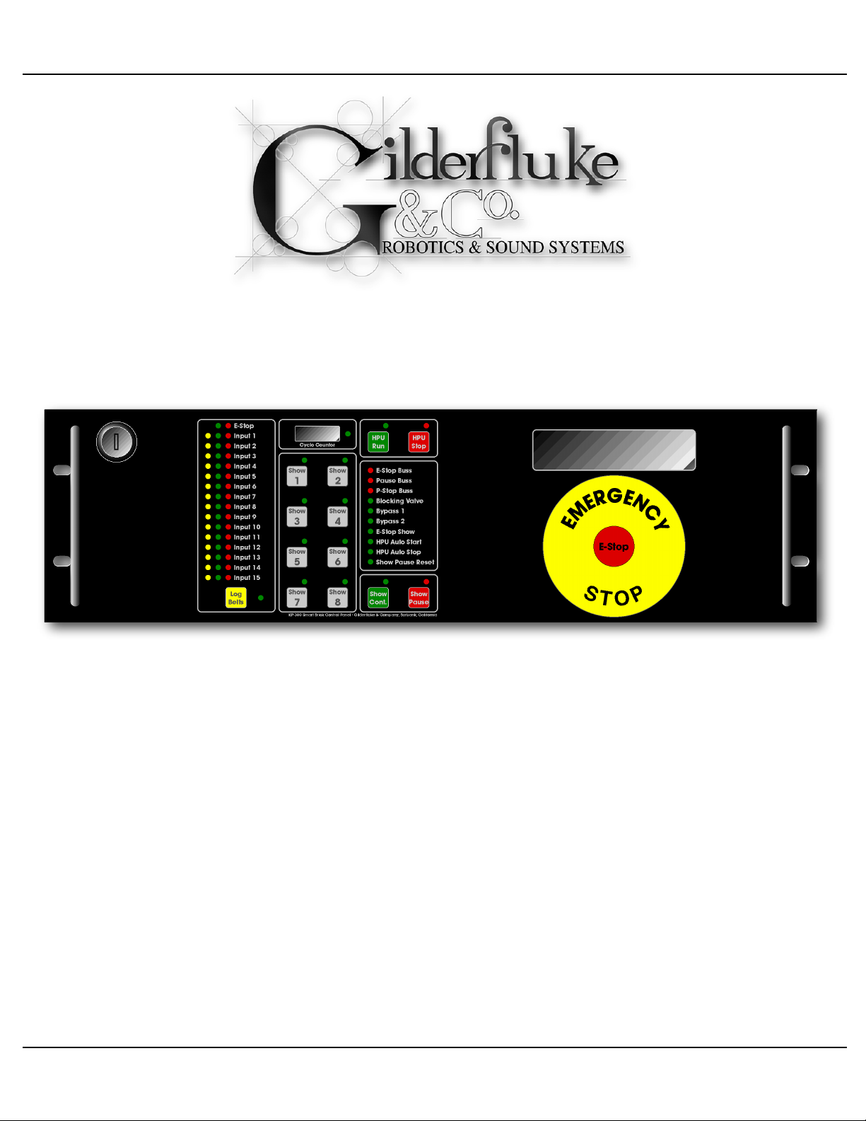
Kp-300
Operator Control Panel
The Kp-300 has all the controls that are needed to run any motion base or other
Smart Brick system. It mounts in 5-1/4” of standard 19” rack space. Operator controls
include buttons for starting and stopping the Hydraulic Power Unit (HPU), pausing and
then continuing a paused show, for ʻloggingʼ occupied seats, and for selecting and playing up to eight different shows.
Because many of the functions of the Kp-300 are safety related, the Kp-300 has no
CPU of any kind. With no microcontroller, there is no possibility of a software crash.
Kp-300 Manual / September 4, 2012 4:29 PM / page 1 of 75
Page 2

Gilderfluke & Co.• 205 South Flower Street • Burbank, California 91502 • 818/840-9484 • 800/776-5972 • fax 818/840-9485
Safety Disclaimer: Any electronic or mechanical sys-
tem has a potential to fail. Certain applications using
Gilderfluke & Company equipment may involve poten-
tial risks of death, personal injury, or severe property, or
environmental damage (“Critical Application”).
Gilderfluke & Company equipment is not designed, in-
tended, authorized, or warranted to be suitable in life
support applications, devices, or systems, or other
critical applications. Inclusion of Gilderfluke & Com-
pany products in such applications is understood to be
fully at the risk of the customer. In order to minimize
risks associated with the customer's applications, ade-
quate design and operating safeguards should be pro-
vided by the customer to minimize inherent or proce-
dural hazards.
Gilderfluke & Company assumes no liability for appli-
cations assistance, customer produced design, soft-
ware performance, or infringement of patents or copy-
rights. Nor does Gilderfluke & Company warrant or rep-
resent that any license, either express, or implied, is
granted under any patent right, copyright, mask work
right, or other intellectual property right of Gilderfluke &
Company covering or relating to any combination, ma-
chine, or process in which Gilderfluke & Company
products or services might be or are used.
Kp-300 Manual / September 4, 2012 4:29 PM / page 2 of 75
Page 3

Gilderfluke & Co.• 205 South Flower Street • Burbank, California 91502 • 818/840-9484 • 800/776-5972 • fax 818/840-9485
...................................................................................Kp-300 Overview! 9
.....................................................................Kp-300 Panel Indicators! 11
..................................................................................Error Input Logged LEDs! 11
....................................................................................Error Input Status LEDs! 11
...................................................................................Error Input Events LEDs! 12
....................................................................................................Log Belts LED! 12
...................................................................................Show Start Button LEDs! 13
..................................................................................Show Cycle Counter LED! 13
...............................................................................................E-Stop Buss LED! 14
......................................................................................Show Pause Buss LED! 15
..........................................................................................HPU Stop Buss LED! 15
...........................................................................................Blocking Valve LED! 16
.........................................................................................Bypass Buss #1 LED! 16
.........................................................................................Bypass Buss #2 LED! 16
...............................................................................E-Stop Show Running LED! 18
......................................................................................Remote HPU Start LED! 18
......................................................................................Remote HPU Stop LED! 18
.....................................................................................Show Pause Reset LED! 18
.............................................................................................HPU Running LED! 19
..............................................................................................HPU Stopped LED! 19
..........................................................................................Show Continue LED! 20
...............................................................................................Show Pause LED! 20
.................................................................DMX-512 Receive LED (v3.0+ Only)! 21
..................................................................Kp-300 Operator Controls! 22
..................................................................................E-Stop Button/Keyswitch! 22
................................................................................................Log Belts Button! 22
...........................................................................................Show Start Buttons! 23
...............................................................................................HPU Start Button! 24
................................................................................................HPU Stop Button! 25
...........................................................................................Show Pause Button! 25
......................................................................................Show Continue Button! 25
...........................................................Kp-300 Jumper Configuration! 27
..................................................................................................Latched E-Stop! 28
.....................................................................................Internal/External Power! 28
..............................................................................................Seat Belt Logging! 29
.......................................................................................................E-Stop Buss! 29
..............................................................................................Show Pause Buss! 29
..............................................................................................Bypass Buss One! 31
..............................................................................................Bypass Buss Two! 31
..................................................................................................HPU-Stop Buss! 32
........................................DipSwitch settings on the Kp-300 (v3.0+)! 34
........................................DipSwitch #1: HPU Stopped LED Internal/External! 34
........................................DipSwitch #2: HPU Running LED Internal/External! 34
...................................................DipSwitch #3: E-Stop Disables Show Starts! 34
..............................................DipSwitch #4: HPU-Stop Disables Show Starts! 34
Kp-300 Manual / September 4, 2012 4:29 PM / page 3 of 75
Page 4

Gilderfluke & Co.• 205 South Flower Street • Burbank, California 91502 • 818/840-9484 • 800/776-5972 • fax 818/840-9485
..........................................DipSwitch #5: Pause Buss Disables Show Starts! 35
.................................................DipSwitch #6: E-Stop Triggers Alarm Output! 35
............................................DipSwitch #7: HPU-Stop Triggers Alarm Output! 35
.........................................DipSwitch #8: Pause Buss Triggers Alarm Output! 36
.........................DMX-512 Address Selection on the Kp-300 (v3.0+)! 37
....................................................................................Sample Shows! 38
.....................................................................................................E-Stop Show1! 38
.....................................................................................................E-Stop Show2! 38
............................................................................................Load/Unload Show! 41
........................................................................................................Main Shows! 43
...........................................................AutoDownloading Shows for a Kp-300! 47
............................................Accessing More Than Eight Shows on a Kp-300! 50
..............................................................................................Delayed ʻHPU Offʼ! 50
...........................................................................Kp-300 Connections! 53
.............................................................Digital Inputs to the Kp-300 (v1.n & v2.n)! 53
.....................................................................DMX-512 Input to the Kp-300 (v3.0+)! 53
.........................................................................Show Start Button LED Inputs! 55
.....................................................................Show Start Button Enable Inputs! 55
...............................................Show Cycle Counter Advance Input to Kp-300! 57
........................................................................Blocking Valve Input to Kp-300! 57
......................................................................Bypass Buss #1 Input to Kp-300! 58
......................................................................Bypass Buss #2 Input to Kp-300! 58
............................................................E-Stop Show Running input to Kp-300! 59
...................................................................Remote HPU Start Input to Kp-300! 60
...................................................................Remote HPU Stop Input to Kp-300! 60
.................................................................Show Pause Reset Input to Kp-300! 60
....................................................24 vdc Power Input to the Kp-300 (v3.0+ Only)! 61
....................................................Kp-300 Expansion for the Kp-300 (v3.0+ Only)! 61
...................................................................................ʻAlarmʼ Output (v3.0+ Only)! 61
...............................................Kp-300 Outputs to Smart Brick Brain! 62
...................................................................Show Select Outputs from Kp-300! 62
..................................................................Green ʻPauseʼ Output from Kp-300! 63
....................................................................Blue ʻE-Stopʼ Output from Kp-300! 63
......................................................................J1 Inputs to the Kp-300! 64
....................................................J2 Inputs & Outputs to the Kp-300! 65
..........................................................................HPU Stopped Input to Kp-300! 65
..........................................................................HPU Running Input to Kp-300! 65
.................................................................Blocking Valve Output from Kp-300! 66
..........................................................................HPU Run Output from Kp-300! 66
...................................................................Remote Log Belts Input to Kp-300! 67
...............................................................Error Inputs Eleven Through Fifteen! 67
..............................................................................Kp-300 Expansion! 69
........................................................................Eight Medium Current Outputs! 69
Kp-300 Manual / September 4, 2012 4:29 PM / page 4 of 75
Page 5

Gilderfluke & Co.• 205 South Flower Street • Burbank, California 91502 • 818/840-9484 • 800/776-5972 • fax 818/840-9485
...........................................................Six High Current Optoisolated Outputs! 70
.................................................................J1 Inputs To The Kp-300 Expansion! 70
............................Thirty-two Optoisolated Inputs To The Kp-300 Expansion! 71
....................................................Kp-300 Installation/Best Practices! 73
...........................................HEXadecimal to Decimal to Percentage! 75
This is not a blank page
Kp-300 Manual / September 4, 2012 4:29 PM / page 5 of 75
Page 6

Gilderfluke & Co.• 205 South Flower Street • Burbank, California 91502 • 818/840-9484 • 800/776-5972 • fax 818/840-9485
A note about this manual:
This manual covers the specifics of the Kp-300. To pro-
gram the Kp-300 you will also want to refer to the
PC•MACs manual sections that cover the PC•MACs
software.
The Kp-300 is typically programmed in ‘Software-only’
or ‘Hardwareless RealTime’ mode. If you are using the USB-
DMX-512 for programming your Kp-300 through the DMX-
512 inputs, please refer to the PC•MACs ‘Unlimited’ mode.
The full PC•MACs manual can be downloaded from our
web site at:
http://www.gilderfluke.com
Kp-300 Manual / September 4, 2012 4:29 PM / page 6 of 75
Page 7

Gilderfluke & Co.• 205 South Flower Street • Burbank, California 91502 • 818/840-9484 • 800/776-5972 • fax 818/840-9485
This isnʼt a blank page either
Kp-300 Manual / September 4, 2012 4:29 PM / page 7 of 75
Page 8
Gilderfluke & Co.• 205 South Flower Street • Burbank, California 91502 • 818/840-9484 • 800/776-5972 • fax 818/840-9485
KP-300 Expansion • Gilderfluke & Company, Burbank, California
Relay Outputs
1/4 J6 Outputs
Inputs
J6 Inputs
3.0 3.1 3.2 3.3 3.4 3.5 3.6 3.7
2.0 2.1 2.2 2.3 2.4 2.5 2.6 2.7
1.0 1.1 1.2 1.3 1.4 1.5 1.6 1.7
0.0 0.1 0.2 0.3 0.4 0.5 0.6 0.7
2019181716151413121110987654321
654321 6543210 7
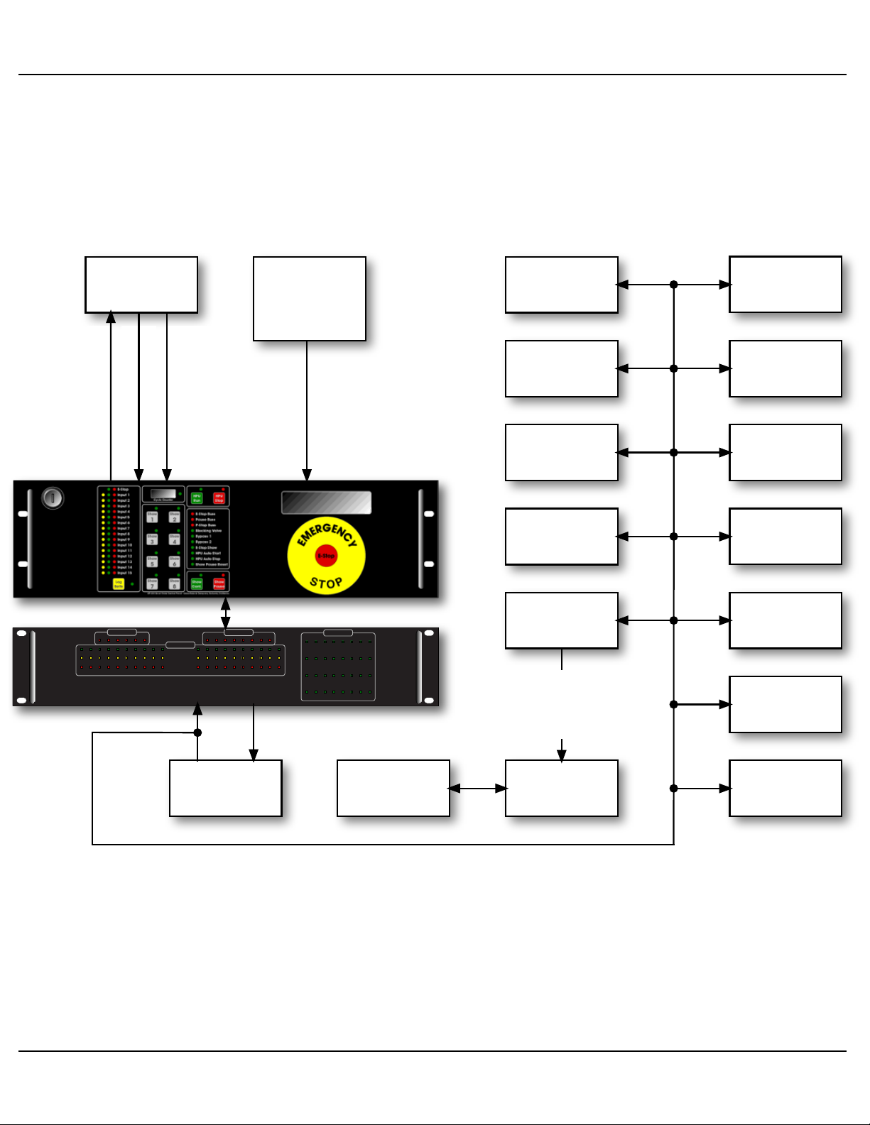
Kp-300 Typical Block Diagram for a Hydraulic Motion Base
HPU
Door, Ramp,
Seat Belt and
other 'Safety'
Switches
HPU error signals
(Oil low, overtemp,
filter dirty, etc.)
HPU Run Output
HPU Run/Stop
Status Signals
Kp-300
Kp-300 Expansion(s)
(if needed)
Pb-DMX with
3.5 Amp
Relays
Audio/Video
Playback
Light Dimmers
RGB LED
Lamp Fixtures
Br-ANA or
DAC-Quad
EFB-Quad(s)
or PID-Quad(s)
Valves, Cylinders
and position
sensors
Moving Head
Light Fixtures
Smog
Machines
Moving head
Light Fixtures
Br-MiniBrick8
Strobe Lights
Fans
other DMX-512
compatible
equipment
Br-Brain4
(typically)
Network
(DMX-512)
Four or
sixteen
0-10 VDC
commands
Kp-300 Manual / September 4, 2012 4:29 PM / page 8 of 75
Page 9

Gilderfluke & Co.• 205 South Flower Street • Burbank, California 91502 • 818/840-9484 • 800/776-5972 • fax 818/840-9485
Kp-300 Overview
The Kp-300 features fifteen safety inputs, plus an onboard E-Stop Button and
Keyswitch that can be used to lock the system. All the safety inputs are ʻfail safeʼ (they
want to see a closure on them and will be triggered by any wire break). With the one exception of the E-Stop Button and Keyswitch on the Kp-300, each safety input can be individually set to force the system to:
Enter an E-Stop condition
Pause the show
Turn the HPU off (if there is one)
The E-Stop Button and Keyswitch on the Kp-300 always force an E-Stop condition.
More safety inputs can be added if needed using the Kp-300 Expansion.
Safety inputs that trigger an E-Stop condition normally include only critical sensors.
An example of these would be a low hydraulic fluid level sensor. If the motion base is
running low on oil, this would trigger an immediate E-Stop, and as long as the oil level
remained low, the Kp-300 would not let you start the HPU. All E-Stops turn the HPU off.
The show always has to be started over from the beginning after an E-Stop.
A pause input is used for less critical sensors. An example of this is where a seat belt
was opened by a rider. The show would instantly be paused and could only be continued by the operator when the condition that caused the pause had been cleared. Alternatively, if after the pause was triggered the operator deemed it necessary to evacuate
the attraction, he could call up a show that parks the motion base or just E-Stop it to
bring it home.
Door sensors are actually a point where a pause is generally safer to use than a full
E-Stop. If a door is opened, instead of returning to home position the motion base will
just freeze. This is less likely to take a leg off someone who is trying to step through the
door.
Two bypass busses are available from the motion profile program. These are used to
temporarily disable inputs that might otherwise cause an error condition to be flagged.
An example of their use is on the door sensors. During the motion base ʻflightʼ, a door
sensor should trigger an error condition (either a pause or E-Stop), but during the Load/
Unload times it should not. For this reason this input would be bypassed during Load/
Unload times by one of the two bypass busses.
Seat belt logging allows any input which has been wired to a seat belt to be ignored
once it has been logged as an unoccupied seat. The seat belt logging can be done from
Kp-300 Manual / September 4, 2012 4:29 PM / page 9 of 75
Page 10

Gilderfluke & Co.• 205 South Flower Street • Burbank, California 91502 • 818/840-9484 • 800/776-5972 • fax 818/840-9485
the Kp-300, remotely via a switch closure, or automatically as part of the motion profile
program.
Each safety input as well as the built in E-Stop Button and Keyswitch have indicator
LEDs that show their current status.
a) A green light means that the input is ʻOKʼ.
b) A yellow light means that the input has been logged as ʻtemporarily unusedʼ.
Typically this is used in an installation that has switches to monitor the seat
belts. Before starting the ride, any inputs from unoccupied seats would be
ʻloggedʼ so that they wonʼt cause an error condition.
c) If an input opens and triggers an error condition, then a red LED will flash
next to that input to flag it as the one that caused the failure. This allows you
to catch short lived error conditions like a HPU level sensor or pressure
switch kicking an E-stop for just an instant.
A solid state counter records the number of show cycles that are run. Shows that are
run with the HPU off or while the system is E-Stopped are not counted. The show cycle
count is retained even during power outages.
With the addition of a three slot card cage (which mounts on the back of the Kp-300),
a Smart Brick Brain, Analog or other Smart Brick (depending on the type of motion base
you are running) and a Z-Brick, the Kp-300 becomes a complete motion base control
system. When ordered in this way, the small LCD that normally is mounted on the front
of a Br-Brain4 is replaced by a large format LCD display on the front of the Kp-300.
Since the entire system is networked, you can put components wherever you like.
Dimmers and the controllers for your ʻ4Dʼ effects can be right in the cabin. The video
playback can be mounted near to the projector or video screen. Just a single shielded
twisted pair of wire connects the DMX-512 to control everything. This can be used to
minimize the number of bulky multi conductor cables that need to be run, especially
those that need to be run in a location that will require continuous flexing. All of this
makes the initial connections, as well as adding new features in the future as simple as
tapping into the existing cable.
Customized front panel artwork is available on the Kp-300. These can be custom
branded, or labeled for specific show names and error inputs. Please contact the
Gilderfluke & Company factory for details on generating custom Kp-300 labels.
Kp-300 Manual / September 4, 2012 4:29 PM / page 10 of 75
Page 11

Gilderfluke & Co.• 205 South Flower Street • Burbank, California 91502 • 818/840-9484 • 800/776-5972 • fax 818/840-9485
Kp-300 Panel Indicators
There are sixty-one LED indicators and one or two LCD displays on the front of the
Kp-300. They are used as follows:
A) Error Input Logged LEDs
(One yellow LED for each Error Input)
! (Fifteen LEDs total)
These are lit to show that an input has been logged as inactive for the
current show. Once an input which is open (green LED is not on) has been
logged, it will be ignored until it is logged as active again. This feature is
typically used to log seat belt inputs. A seat which is unoccupied will be
logged so that it canʼt cause an E-Stop or Pause if it changes state during
the show.
Seat belts can be logged at any time that the Show Pause Reset Input
from the Smart Brick System is active. When this input is active, the safety
inputs can be logged by either pressing the Log Belts button or activating the
Remote Log Belts Input by pressing Remote Log Belts Button(s) attached to
it. If you want to automatically log belts from the motion profile, just set the
Remote Log Belts Input for Internal Power and attach the two wires for this
input together so it is always active. Whenever the Show Pause Reset Input
is programmed active, the inputs that are set to be logged will automatically
be logged.
Input logging actually takes place at the instant that the Log Belts Button,
Log Belts Remote Input, or Show Pause Reset Input are released. The LED
next to the Log Belts Button will light whenever the seat belts are being
logged.
B) Error Input Status LEDs
(One green LED for each Error Input, plus one for the E-Stop Button/
Keyswitch)
! (Sixteen LEDs total)
These are lit to show that an input is in its ʻsafeʼ condition. If any one of
these inputs is off and that input hasnʼt been logged as an unoccupied seat
(yellow LED IS on), then it is not safe to start the show.
Kp-300 Manual / September 4, 2012 4:29 PM / page 11 of 75
Page 12

Gilderfluke & Co.• 205 South Flower Street • Burbank, California 91502 • 818/840-9484 • 800/776-5972 • fax 818/840-9485
All the inputs are configured to ʻfail safeʼ, which is to say that an error is
triggered by an open circuit on an input. This is true even for the Kp-300ʼs E-
Stop Button and Keyswitch. These are wired in series and trigger an E-Stop
if this connection is opened at any point.
C) Error Input Events LEDs
(One red LED for each Error Input, plus one for the E-Stop Button/Keyswitch)
! (Sixteen LEDs total)
These LEDs flash on the input(s) that triggered an error condition. They
allow you to find which input caused the error, even if it only existed for an
instant.
An example of this featureʼs use is in events like a HPU filter dirty sensor
which has been configured to trigger an E-Stop event. The dirty filter sensor
on the HPU is typically a differential pressure switch which measures the
pressure across the filter. If this pressure gets too high, then the switch
opens to indicate a clogged filter and triggers the E-Stop condition. The thing
that makes this hard to catch is that the E-Stop turns off the HPU, so the differential pressure immediately drops back into zero (the ʻOKʼ region, as far
as the switch is concerned), turning back on the green Error Input Status
LED for the input. To further complicate things, because the HPU potentially
turned off right in the middle of a show, the ʻlow pressureʼ error input (if there
is one) will turn off its green Error Input Status LED because the pressure
just went to zero. Under these circumstances the only Error Input Event LED
that will be flashing will be the original ʻDirty Filterʼ one that initiated the EStop in the first place. All the other Error Input Event LEDs will be off.
Once these LEDs are turned on by an E-Stop event, they can only be
cleared when the operator starts the next show. They will keep flashing until
the next show is started. If they were triggered by a Show Pause event, they
will stop flashing but remain lit after the error condition is cleared and the
show is ʻresumedʼ. They will be cleared when there is another E-Stop/Show
Pause event or the next show is started by the operator.
D) Log Belts LED
(One yellow LED)
This LED turns on when the error inputs are are being logged as temporarily unused. Seat belts can be logged at any time that the Show Pause
Reset Input from the Smart Brick System is active. When this input is active,
Kp-300 Manual / September 4, 2012 4:29 PM / page 12 of 75
Page 13

Gilderfluke & Co.• 205 South Flower Street • Burbank, California 91502 • 818/840-9484 • 800/776-5972 • fax 818/840-9485
the safety inputs can be logged by either pressing the Log Belts Button or
activating the Remote Log Belts Input by pressing Remote Log Belts But-
ton(s) attached to it. If you want to automatically log belts from the motion
profile, just set the Remote Log Belts Input for Internal Power and attach the
two wires for this input together so it is always active. Whenever the Show
Pause Reset Input is programmed active, the inputs that are set to be
logged will automatically be logged.
Input logging actually takes place at the instant that the Log Belts Button,
Log Belts Remote Input, or Show Pause Reset Input are released.
E) Show Start Button LEDs
(One green LED for each Show Start Button)
! (Eight LEDs total)
These LEDs are controlled directly by the motion control profile stored in
the Smart Brick System. This allows the LEDs to be programmed on, off or
flashing as desired at any point in time. They are programmed to indicate
which shows are available to the operator, or to indicate which show is already running. We typically program them in a chase pattern, lighting only
the valid show selections. Once a show has started, we typically program all
but the selected Show Start Button LEDs off, and flash the selected show
LED a few times before turning it on through the rest of the show. If any
other show selection is valid while another show is running, we then flash it
discretely throughout the show that is running.
Whenever a Show Start Button LED is programed to indicate that a Show
Start Button is valid, it is also necessary to actually enable the correspond-
ing Show Start Button Enable Input output from the Smart Brick System to
make the Show Start Buttons active. If this is not done, then the Show Start
Buttons will remain inactive.
F) Show Cycle Counter LED
(One green LED)
This LED lights to show that the show cycle counter has been commanded to advance by the motion control profile stored in the Smart Brick
System. The count on the LCD counter will advance by one if the Kp-300 is
not currently in any type of E-Stop condition and the HPU is running, as indicated by 24 vdc being received on the HPU Running Input.
Kp-300 Manual / September 4, 2012 4:29 PM / page 13 of 75
Page 14

Gilderfluke & Co.• 205 South Flower Street • Burbank, California 91502 • 818/840-9484 • 800/776-5972 • fax 818/840-9485
The Show Cycle Count Advance Input pulse is typically programmed to
take place towards the end of the motion base program. This lets a show
which is aborted for any reason not be counted.
The LCD module that displays the current show cycle count permanently
stores the count each time it is advanced. The count will be retained even if
power is removed from the Kp-300. Please contact the Gilderfluke & Co. factory if you need a resettable cycle counter.
G) E-Stop Buss LED
(One red LED)
This LED lights to show that the Kp-300 currently has an unresolved EStop condition. The beginning of any E-Stop event stops the HPU (if there is
one), disables the Blocking Valve output and triggers the Smart Brick Sys-
tem to play the E-Stop Show through the Blue ʻE-Stopʼ Input to the Smart
Brick Brain. Calling up the E-Stop show sets the ʻE-Stop Show Runningʼ
output from the Smart Brick System (this must be programmed into the motion profile of the E-Stop show). This resets the first of the two E-Stop
latches on the Kp-300. At this point you can start the HPU and any shows
that have been enabled in the motion control profile of the E-Stop Show.
If this LED is ON, you should not run the show unless you just want to
see the video and sound, without any motion. If a show is started while there
is still an unresolved E-Stop condition, the Kp-300 can be configured to:
a) Lock out the ʻBlocking Valveʼ output until another show is started
with the E-Stop Buss LED off. This is the safer of the two options, because the motion base will not start moving until a show
is started cleanly.
b) Lock out the ʻBlocking Valveʼ output until the E-Stop condition is
cleared. This can allow the motion base to spring into movement
if the E-Stop condition is resolved half way through the show.
If you want to disallow shows to be run at all if there is an E-Stop condition present, you can configure one of the two bypass busses to momentar-
ily (for just one frame) bypass all the possible E-Stop error inputs at the very
beginning of all shows1. At the end of the bypass buss pulse, any error conditions that remain will trigger the E-Stop to keep even the video and audio
1
This technique is flexible enough that you can even leave it out of any maintenance shows that you want to be able to run without
motion
Kp-300 Manual / September 4, 2012 4:29 PM / page 14 of 75
Page 15

Gilderfluke & Co.• 205 South Flower Street • Burbank, California 91502 • 818/840-9484 • 800/776-5972 • fax 818/840-9485
from running. This technique should be used in applications that donʼt use
the Blocking Valve Output. Typical of these are most electric motion base in-
stallations.
H) Show Pause Buss LED
(One red LED)
This LED lights to show that the Kp-300 currently has an unresolved
Show Pause condition. If this LED is ON, you should not run the show.
When the Show Pause Reset Input from the Smart Brick System goes
away2, the Kp-300 will be paused. The condition that caused the Show
Pause will then have to be cleared before the current show can be resumed.
Alternatively, the operator can bail out by pressing the E-Stop or running another show that simply gets the operator back to the Load/Unload shows
without triggering an E-Stop.
I) HPU Stop Buss LED
(One red LED)
This LED lights to show that the Kp-300 currently has an unresolved HPU
Stop condition. If this LED is ON, you should not run the show. The Kp-300
will keep the operators from starting the HPU until this condition is resolved.
The error conditions that are typically used to trigger a HPU Stop Buss event
are those which might cause damage to the HPU, Motion base or their riders. Typical of these are ʻHPU Oil Level Lowʼ or ʻHPU Over Temperatureʼ
sensors.
It is not unusual for operators to try to override this type of safety feature.
For this reason, many HPU applications use a number of techniques to lock
out the show if the HPU is turned on locally:
a) The primary technique is to run the HPUʼs 24 vdc ʻHPU Stoppedʼ
and ʻHPU Runningʼ outputs through the ʻAutoʼ position of the
HPU ʻHand/Off/Manualʼ switch on the way to the Kp-300. By doing this, both the HPU LEDs on the Kp-300 will be off unless the
HPU is in the ʻAutoʼ mode. This has the added advantage of giving the operators a remote indication of the position of the HPUʼs
ʻHand/Off/Manualʼ switch.
b) The ʻAutoʼ position of the HPUʼs ʻHand/Off/Manualʼ switches on
2
Usually at the start any of the Main shows. It is normally programmed as active during the E-Stop and Load/Unload shows
Kp-300 Manual / September 4, 2012 4:29 PM / page 15 of 75
Page 16

Gilderfluke & Co.• 205 South Flower Street • Burbank, California 91502 • 818/840-9484 • 800/776-5972 • fax 818/840-9485
the HPUs wired into one of the error inputs of the Kp-300. This
input is configured to keep the motion base from running if the
HPU ʻHand/Off/Manualʼ switch is in anything but the ʻAutoʼ position.
c) The Blocking Valve Output from the Kp-300 can be run through
the ʻAutoʼ position of the HPU ʻHand/Off/Manualʼ switch. Unless
the HPU is started by the Kp-300, this too will prevent the motion
base from moving. This will only work on hydraulic motion bases
that use a blocking valve.
J) Blocking Valve LED
(One green LED)
This LED lights to show that the motion control profile stored in the Smart
Brick System has enabled the Blocking Valve to allow the motion base to
move. If the Kp-300 is still in an E-Stop condition or the HPU is not running
(as indicated by 24 vdc being received on the HPU Running Input), this LED
will simply flash and the Blocking Valve output will not be activated. If a show
is started while there is still an unresolved E-Stop condition, the Kp-300 can
be configured to:
a) Lock out the ʻBlocking Valveʼ output until another show is started
with the E-Stop Buss LED off. This is the safer of the two options, because the motion base will not start moving until a show
is started cleanly.
b) Lock out the ʻBlocking Valveʼ output until the E-Stop condition is
cleared. This can allow the motion base to spring into movement
if the E-Stop condition is resolved half way through the show.
K) Bypass Buss #1 LED
L) Bypass Buss #2 LED
(Two green LEDs)
These LEDs lights to show that the motion control profile has been programmed to bypass some or all the Safety inputs which have been configured to create an E-Stop or Show Pause. Typical examples of the use of the
bypass buss are:
a) HPU Startup/Shutdown: If the HPU is started and stopped as
part of the motion profile, there will usually be a time just after it
Kp-300 Manual / September 4, 2012 4:29 PM / page 16 of 75
Page 17

Gilderfluke & Co.• 205 South Flower Street • Burbank, California 91502 • 818/840-9484 • 800/776-5972 • fax 818/840-9485
is started and a time after it is stopped where any HPU pressure
sensors inputs will need to be bypassed. Do this by programming the Bypass Buss you are using and Remote HPU Start In-
put to be active at the beginning of the show. The Bypass Buss
needs to be active for the time it takes for the HPU to build up
pressure. If the pressure doesnʼt come up during the time allotted, the Kp-300 will automatically trigger an error condition (either E-Stop or Show Pause, as configured).
# If the HPU is to be turned off at the end of the show, then the
Bypass Buss which is being used would be programmed active
along with a pulse on the Remote HPU Stop Input. This allows
the HPU to be stopped without triggering an error condition. If
configured to trigger an E-Stop, the Bypass Buss will also need
to be programmed active during the E-Stop and Load/Unload
shows so that the HPUʼs low pressure wonʼt trigger an error during these shows when the HPU is off.
b) Door Sensors: If the door or floor mat sensors inputs are set to
trigger an E-Stop, they will need to be bypassed during the EStop and Load Unload shows. This is because although you
want these inputs to trigger an error while the motion base is in
flight, you donʼt want this to trigger an E-Stop when the doors are
opened for the passengers to be loaded and unloaded.
c) Electric Motion Bases and other Installations that donʼt use
the Kp-300 Blocking Valve Output: If you donʼ t want to allow
shows to be run if there is an E-Stop condition present, you can
configure one of the two bypass busses to momentarily (for just
one frame) bypass all the possible error inputs at the very start
of all shows3. At the end of the Bypass Buss pulse, any error
conditions that remain will trigger the E-Stop. This technique
should be used in applications that donʼt use the Blocking Valve
Output. Typical of these are most electric motion base installa-
tions.
If you are using the Seat Belt Logging features of the Kp-300, be sure you
donʼt configure the Kp-300 to bypass any inputs that are to be logged during
the time during which they need to be logged. Bypassing an input will con-
3
This technique is flexible enough that you can even leave it out of any maintenance shows that you want to be able to run without
motion.
Kp-300 Manual / September 4, 2012 4:29 PM / page 17 of 75
Page 18

Gilderfluke & Co.• 205 South Flower Street • Burbank, California 91502 • 818/840-9484 • 800/776-5972 • fax 818/840-9485
vince the Kp-300 that the inputs are in the ʻsafeʼ position, and so they will not
be logged as ʻunoccupiedʼ.
The Show Pause functions are usually disabled during the E-Stop and
Load/Unload shows by the Show Pause Reset Input from the Smart Brick
System. Inputs that trigger a Show Pause are never needed during the EStop and Load/Unload shows anyway, so there is no need to bypass them
separately during these shows.
M)E-Stop Show Running LED
One green LED
This LED lights to show that the motion control profile is running the EStop Show. The E-Stop Show Running output is normally only programmed
active during the E-Stop Show, and is used reset one of the Kp-300ʼs onboard latches to allow the HPU to be started and the E-Stop conditions to be
cleared.
N) Remote HPU Start LED
O) Remote HPU Stop LED
(Two green LEDs)
These LEDs light to show that the motion control profile on the Smart
Brick System has had the commands to start or stop the HPU embedded in
it. This is an optional feature. If you donʼt want the HPU to be started and
stopped automatically, just donʼt use them.
These outputs parallel the HPU Start Button and HPU Stop Button that
are on the front of the Kp-300. If the HPU is being forced off by a HPU Stop
Buss error, the Remote HPU Start Input can NOT override the error.
Any of the ʻstopʼ inputs take precedence over any of the ʻstartʼ inputs. You
can use an active Remote HPU Stop Input in the motion profile stored on the
Smart Brick System to keep the operator or Remote HPU Start Input from
starting the HPU.
P) Show Pause Reset LED
(One green LED)
This LED lights to show that the motion control profile on the Smart Brick
System has the Show Pause Reset Input command programmed to reset or
Kp-300 Manual / September 4, 2012 4:29 PM / page 18 of 75
Page 19

Gilderfluke & Co.• 205 South Flower Street • Burbank, California 91502 • 818/840-9484 • 800/776-5972 • fax 818/840-9485
disable the Kp-300 Show Pause functions. This is normally programmed active only during the E-Stop and Load/Unload shows.
Seat belts can be logged at any time that the Show Pause Reset Input
from the Smart Brick System is active. When this input is active, the safety
inputs can be logged by either pressing the Log Belts button or activating the
Remote Log Belts Input by pressing Remote Log Belts Button(s) attached to
it. If you want to automatically log belts from the motion profile, just set the
Remote Log Belts Input for Internal Power and attach the two wires for this
input together so it is always active. Whenever the Show Pause Reset Input
is programmed active, the inputs that are set to be logged will automatically
be logged.
Input logging actually takes place at the instant that the Log Belts Button,
Remote Log Belts Input, or Show Pause Reset Input are released. The LED
next to the Log Belts Button will light whenever the seat belts are being
logged.
Q) HPU Running LED
(One green LED)
This LED lights to show that the Hydraulic Power Unit (HPU) is running.
This LED is turned on only when a 24 vdc signal is applied to the HPU Run-
ning Input. This signal normally comes from the HPU. If there is no HPU in
the system, this input can be permanently attached to a 24 vdc or the HPU
Run Output.
Unless this signal is received by the Kp-300, the Blocking Valve Output
will never turn on and the Show Cycle Counter will not advance.
To help keep shows from being run when the HPU has been started by its
local Hand/Off/Auto switch, the HPU Stopped Input and HPU Running Input
signals are often routed through the ʻAutoʼ position on the switch. If the
switch isnʼt in the ʻAutoʼ position, the HPU Stopped LED and HPU Running
LED wonʼt light and the Blocking valve wonʼt be enabled.
R) HPU Stopped LED
(One red LED)
This LED lights to show that the Hydraulic Power Unit (HPU) is not running. This LED is turned on only when a 24 vdc signal is applied to the HPU
Kp-300 Manual / September 4, 2012 4:29 PM / page 19 of 75
Page 20

Gilderfluke & Co.• 205 South Flower Street • Burbank, California 91502 • 818/840-9484 • 800/776-5972 • fax 818/840-9485
Stopped Input. Unlike the HPU Running Input, this input is not used for any
other purpose than lighting this LED.
To help keep shows from being run when the HPU has been started by its
local Hand/Off/Auto switch, the HPU Stopped Input and HPU Running Input
signals are often routed through the ʻAutoʼ position on the switch. If the
switch isnʼt in the ʻAutoʼ position, the HPU Stopped LED and HPU Running
LED wonʼt light and the Blocking valve wonʼt be enabled.
S) Show Continue LED
(One green LED)
This LED lights to show that the Motion profile on the Smart Brick System
has been programmed with the Show Pause Reset Input inactive and that
the current show has not been paused.
When a show is paused, the Kp-300 sends a signal to the Smart Brick
Brain through its Green ʻPauseʼ Output. The Smart Brick Brain input must be
configured to pause the currently running show on a closure on this input4.
When a show is 'continued', the signal is dropped on the Green ʻPauseʼ
Output to the Smart Brick Brain. This input must be configured to continue
the currently running show on an opening on this input.
Once a show has been paused, the only two ways to 'continue' a show
are to:
a) Send an active signal from the Smart Brick System to the Kp-
300ʼs Show Pause Reset Input.
b) Once the condition that caused the Show Pause has been re-
moved, the operator can press the Show Continue button.
T) Show Pause LED
(One red LED)
This LED lights to show that the Motion profile on the Smart Brick System
has been programmed with the Show Pause Reset Input inactive and that
the current show has been paused by the operator pressing the Show
Pause Button or an error condition.
When a show is paused, the Kp-300 sends a signal to the Smart Brick
Brain through its Green ʻPauseʼ Output. The Smart Brick Brain input must be
4
In some applications, you may want to call up a different show using this input, instead of pausing the current show.
Kp-300 Manual / September 4, 2012 4:29 PM / page 20 of 75
Page 21

Gilderfluke & Co.• 205 South Flower Street • Burbank, California 91502 • 818/840-9484 • 800/776-5972 • fax 818/840-9485
configured to pause the currently running show on a closure on this input5.
When a show is 'continued', the signal is dropped on the Green ʻPauseʼ
Output to the Smart Brick Brain. This input must be configured to continue
the currently running show on an opening on this input.
Once a show has been paused, the only two ways to 'continue' a show
are to:
a) Send an active signal from the Smart Brick System to the Kp-
300ʼs Show Pause Reset Input.
b) Once the condition that caused the Show Pause has been re-
moved, the operator can press the Show Continue button.
U) DMX-512 Receive LED (v3.0+ Only)
(One red LED, Located on back of Kp-300)
To support the DMX-512 input, the v3.0+ Kp-300 adds an LED that
flashes on each update via the DMX-512.
The Kp-300 requires DMX-512 that includes GilderChecksums.
If receiving DMX-512 without valid checksums, the DMX-512 Receive
LED on the back of the Kp-300 will not flash and only the Show Start Button
LEDs will follow the incoming the DMX-512. The signals like the Show Start
Button Enable Inputs, blocking valve enable, and automatic HPU start/stop
will not work if the GilderChecksums are invalid.
5
In some applications, you may want to call up a different show using this input, instead of pausing the current show.
Kp-300 Manual / September 4, 2012 4:29 PM / page 21 of 75
Page 22

Gilderfluke & Co.• 205 South Flower Street • Burbank, California 91502 • 818/840-9484 • 800/776-5972 • fax 818/840-9485
Kp-300 Operator Controls
The Kp-300 has just a small number of operator controls. Most of these have LEDs
that can be lit under program control, or indicate their current status.
A) E-Stop Button/Keyswitch
These two switches are wired in series. Opening either one will cause an
E-Stop and HPU Stop event on the Kp-300. The beginning of any E-Stop
event stops the HPU (if there is one), disables the Blocking Valve output and
triggers the Smart Brick System to play the E-Stop Show through the Blue
ʻE-Stopʼ Input to the Smart Brick Brain. Calling up the E-Stop show sets the
ʻE-Stop Show Runningʼ output from the Smart Brick System (this must be
programmed into the motion profile of the E-Stop show). This resets the first
of the two E-Stop latches on the Kp-300. At this point you can start the HPU
and any shows that have been enabled in the motion control profile of the EStop Show.
The E-Stop switch has a red mushroom-style cap. Once pushed, the button latches in the E-Stopped position. To release the cap, it is rotated clockwise. The E-Stop button has a spare set SPDT set of contacts available for
your use. Users of Moog electric motion bases can use this switch closure
for the hardware E-Stop input they require.
The Keyswitch is typically used to lock unauthorized users from starting
the HPU or running shows with motion. The Keyswitch can be turned to one
of two positions. The key can be removed in either of these two positions.
The show can be run without motion while the keyswitch is turned off or
the E-Stop button has been pushed in. If you want to disallow shows to be
run at all if there is an E-Stop condition present, you can use the DipSwitch
#3, DipSwitch #4 or DipSwitch #5 to disallow running shows if there is an er-
ror condition.
B) Log Belts Button
Seat belts can be logged at any time that the Show Pause Reset Input
from the Smart Brick System is active. When this input is active, the safety
inputs can be logged by either pressing the Log Belts button or activating the
Remote Log Belts Input by pressing Remote Log Belts Button(s) attached to
it. If you want to automatically log belts from the motion profile, just set the
Remote Log Belts Input for Internal Power and attach the two wires for this
Kp-300 Manual / September 4, 2012 4:29 PM / page 22 of 75
Page 23

Gilderfluke & Co.• 205 South Flower Street • Burbank, California 91502 • 818/840-9484 • 800/776-5972 • fax 818/840-9485
input together so it is always active. Whenever the Show Pause Reset Input
is programmed active, the inputs that are set to be logged will automatically
be logged.
Input logging actually takes place at the instant that the Log Belts Button,
Remote Log Belts Input, or Show Pause Reset Input are released. The LED
next to the Log Belts Button will light whenever the seat belts are being
logged.
C) Show Start Buttons
(Eight Buttons)
The Kp-300 has been designed to support up to eight shows which can
be directly accessed. If more shows are needed, these Show Start Buttons
can be bypassed with a Kp-100 or Kp-200 to allow access to the Smart Brick
Systemʼs 255 show capacity.
Which shows are available to the user (which of these eight Show Start
Buttons are enabled), is controlled as a function of the motion profile running
on the Smart Brick System. Enabling a Show Start Buttons just requires set-
ting the appropriate Show Start Button Enable Inputs in the motion profile.
Any or all of the Show Start Buttons can be enabled/disabled at any time.
The Show Start Button LEDs next to these buttons are also controlled as
part of the motion profile. This allows the Show Start Button LEDs to be pro-
grammed on, off or flashing as desired at any point in time.
Typically the Show Start Buttons are programmed as active during the E-
Stop and Load/Unload shows. During the main shows, typically none of
them are enabled. If any are enabled, then the user can jump directly out of
the currently running show and into the one(s) that have been enabled. This
is sometimes used to enable a ʻparkʼ show that brings the motion base home
without having to do anything as drastic as an E-Stop. Any show that is enabled while another show is running will be enabled even during a show
pause. Make sure that if you are using this technique, that the show that is
jumped into has the Show Pause Reset Input set for at least a few frames at
the beginning. Otherwise the new show will begin running, but the Show
Pause functions of the Kp-300 wonʼt be reset (the Show Pause LED will remain lit, and the next Show Pause event will be ignored). At the end of the
pulse on the Show Pause Reset Input, the Kp-300 will check for an outstanding Show Pause condition. If one still persists, then the new show will
be paused.
Kp-300 Manual / September 4, 2012 4:29 PM / page 23 of 75
Page 24

Gilderfluke & Co.• 205 South Flower Street • Burbank, California 91502 • 818/840-9484 • 800/776-5972 • fax 818/840-9485
If shows must be run in a certain order, you can program this into the motion profile stored on the Smart Brick System. An example of this would be a
motion base that has separate entrance and exit doors. The main shows all
lead into a show that leaves the exit doors opened6. The only show that is
enabled for the operator is a short show that closes the exit doors (and
maybe turns off the cabin lights) so that the system is ready to be parked or
loaded with the next group of riders. The operator would start this show once
he confirmed that the cabin was clear. At the end of this show another show
is enabled that opens the entrance door (and turns on the cabin lights). The
operator would call this up when it is time to load the next batch of riders. At
the end of this short show, the main shows are enabled for the operators.
One of these would be started once all the riders were safely seated (and
the belts logged, if needed). All of these short shows can have accompanying audio and/or video if it has been programmed on whatever audio/image
source is being used.
The Br-ANA Analog Output Smart Brick can be configured to do an Ease
In whenever the Smart Brick System jumps from one show to another. This
makes it safe for you to configure the system to jump between shows as described above.
D) HPU Start Button
This Button is used to set the latch on the Kp-300 that turns on the HPU
Run Output. This is an optional feature. If you donʼt want the HPU to be
started and stopped remotely, just donʼt use this button.
The HPU Start Button parallels the Remote HPU Start Input from the
Smart Brick System. If the HPU is being forced off by a HPU Stop Buss error
or a Remote HPU Stop Input from the Smart Brick System, the HPU Start
Button can not override them.
Any of the ʻstopʼ inputs take precedence over any of the ʻstartʼ inputs. You
can use an active Remote HPU Stop Input in the motion profile stored on the
Smart Brick System to keep the operator or Remote HPU Start Input from
starting the HPU.
6
If the motion base has exit doors that must be operated only when the operator deems it safe, all the main shows can leave only
the button to jump to a short show that opens the doors for the operators.
Kp-300 Manual / September 4, 2012 4:29 PM / page 24 of 75
Page 25

Gilderfluke & Co.• 205 South Flower Street • Burbank, California 91502 • 818/840-9484 • 800/776-5972 • fax 818/840-9485
E) HPU Stop Button
This Button is used to reset the latch on the Kp-300 that turns on the HPU
Run Output. This is an optional feature. If you donʼt want the HPU to be
started and stopped remotely, just donʼt use this button.
The HPU Stop Button parallels the Remote HPU Stop Input from the
Smart Brick System.
F) Show Pause Button
This button is used to set the latch on the Kp-300 that sends a pause
command to the Smart Brick Brain through the Green ʻPauseʼ Output. This
latch can also be set by any error condition that has been configured to start
a Show Pause event. If the Show Pause Reset Output from the Smart Brick
System is active, then the Show Pause latch can not be set by either this
button or an error condition.
When a show is paused, the Kp-300 sends a signal to the Smart Brick
Brain through its Green ʻPauseʼ Output. The Smart Brick Brain input must be
configured to pause the currently running show on a closure on this input7.
When a show is 'continued', the signal is dropped on the Green ʻPauseʼ
Output to the Smart Brick Brain. This input must be configured to continue
the currently running show on an opening on this input.
Once a show has been paused, the only two ways to 'continue' a show
are to:
a) Send an active signal from the Smart Brick System to the Kp-
300ʼs Show Pause Reset Input.
b) Once the condition that caused the Show Pause has been re-
moved, the operator can press the Show Continue button.
G) Show Continue Button
This button is used to reset the latch on the Kp-300 that sends a pause command to the Smart Brick Brain through the Green ʻPauseʼ Output. This latch can
also be set by any error condition that has been configured to start a Show Pause
event.
When a show is paused, the Kp-300 sends a signal to the Smart Brick Brain
through its Green ʻPauseʼ Output. The Smart Brick Brain input must be configured
7
In some applications, you may want to call up a different show using this input, instead of pausing the current show.
Kp-300 Manual / September 4, 2012 4:29 PM / page 25 of 75
Page 26

Gilderfluke & Co.• 205 South Flower Street • Burbank, California 91502 • 818/840-9484 • 800/776-5972 • fax 818/840-9485
to pause the currently running show on a closure on this input8. When a show is
'continued', the signal is dropped on the Green ʻPauseʼ Output to the Smart Brick
Brain. This input must be configured to continue the currently running show on an
opening on this input.
Once a show has been paused, the only two ways to 'continue' a show are to:
a) Send an active signal from the Smart Brick System to the Kp-
300ʼs Show Pause Reset Input.
b) Once the condition that caused the Show Pause has been re-
moved, the operator can press the Show Continue button.
8
In some applications, you may want to call up a different show using this input, instead of pausing the current show.
Kp-300 Manual / September 4, 2012 4:29 PM / page 26 of 75
Page 27

Gilderfluke & Co.• 205 South Flower Street • Burbank, California 91502 • 818/840-9484 • 800/776-5972 • fax 818/840-9485
Kp-300 Jumper Configuration
There are about seventy-five jumpers that must be set on the Kp-300 before it can be
used. Not to worry though, each of the fifteen safety inputs has only five options that you
can choose. There is also one jumper that globally affects the E-Stop latches. The
jumpers are located on the back of the printed circuit board that is used in the Kp-3009.
If larger quantities of Kp-300s are to be ordered, we can provide them with jumpers already in the desired positions or permanently soldered into place so that they can not be
easily moved.
Kp-300 PCB (Rear View)
The jumpers for all the error inputs are arranged in a series of horizontal rows. As
you can see, the number of the input is shown next to the row which it configures. The
function of each jumper position is also silkscreened next to the jumpers. We would rec-
9
We can build Kp-300s with the jumpers on the front of the printed circuit board to restrict access if so desired. Please contact the
factory if you would be interested in such a modification.
Kp-300 Manual / September 4, 2012 4:29 PM / page 27 of 75
Page 28

Latched E-Stop
Yes
Latched E-Stop
No
External Power Internal Power
Gilderfluke & Co.• 205 South Flower Street • Burbank, California 91502 • 818/840-9484 • 800/776-5972 • fax 818/840-9485
ommend that you document the final positions of all jumpers by marking them on the
drawing above (or a copy of it) The jumpers are:
A) Latched E-Stop
This is the only jumper that is not related to the fifteen individual safety
inputs.
In the ʻYesʼ position, if a show is started while there is an E-Stop condition
still present, the Kp-300 will not allow you to enable the Blocking Valve Out-
put until the show has finished, even if the E-Stop input is cleared. This al-
lows you to safely run test shows without movement after an E-Stop10.
If this jumper is in the ʻNoʼ position, if a show is started while there is an
E-Stop condition still present, the Kp-300 will allow you to enable the Block-
ing Valve Output once the E-Stop input is cleared. This means that the
movement may be enabled by the Blocking Valve Output part way through a
show when the E-Stop condition is cleared.
B) Internal/External Power
(One set of jumpers for each safety input and one set for the Remote Log Belt
Input)
Sixteen sets of jumpers in total
The fifteen Safety Inputs and one Remote Belt Log Input are optically iso-
lated to 1500 volts. This jumper sets whether the optoisolators use the same
power as the Kp-300 or if you must provide them with an external source of
24 vdc power. Use the Internal Power if you are going to be attaching these
inputs to a simple switch closures. Use the External setting if you are using a
device that provides power.
When possible try to use external power. When doing so, a high voltage
spike on an externally powered input line cannot get into the Kp-300 and
damage it.
10
# Assuming that the Blocking Valve Output is used in the installation.
Kp-300 Manual / September 4, 2012 4:29 PM / page 28 of 75
Page 29

Not Logging Input Logged
E-Stop Show Pause
Gilderfluke & Co.• 205 South Flower Street • Burbank, California 91502 • 818/840-9484 • 800/776-5972 • fax 818/840-9485
C) Seat Belt Logging
(One jumper for each safety input)
The fifteen Safety Inputs can be set to be ʻLoggedʼ either manually or
automatically.
Once an input which is open (green LED is not on) has been logged, it
will be ignored until it is logged as active again. This feature is typically used
(as its name implies) to log seat belt inputs. A seat which is unoccupied will
be logged so that it canʼt cause an E-Stop or Pause if it changes state during
the show. A yellow LED indicates an input which has been logged.
The jumper for an input should be placed in the Log Belts position if it is
to be logged. The jumper should be placed on the No Logging position if it is
not to be logged.
Seat belts can be logged at any time that the Show Pause Reset Input
from the Smart Brick System 1/3 J6 is active. When this input is active, the
safety inputs can be logged by either pressing the Log Belts button or activating the Remote Log Belts Input by pressing Remote Log Belts Button(s)
attached to it.
If you want to automatically log belts from the motion profile, just set the
Remote Log Belts Input for Internal Power and attach the two wires for this
input together so it is always active. Whenever the Show Pause Reset Input
is programmed active, the inputs that are set to be logged will automatically
be logged.
Input logging actually takes place at the instant that the Log Belts Button,
Remote Log Belts Input, or Show Pause Reset Input are released. The LED
next to the Log Belts Button will light whenever the seat belts are being
logged.
D) E-Stop Buss
E) Show Pause Buss
(One jumper for each safety input)
Any or all of the fifteen Safety Inputs can be set to trigger either an EStop or Show Pause.
Kp-300 Manual / September 4, 2012 4:29 PM / page 29 of 75
Page 30

Gilderfluke & Co.• 205 South Flower Street • Burbank, California 91502 • 818/840-9484 • 800/776-5972 • fax 818/840-9485
By moving the jumper to the E-Stop position, an input will trigger an EStop show when it opens. Moving it to the Show Pause position will cause
an input to pause the show when it opens. If this input is not being used for
either an E-Stop or Show Pause, it should be removed.
Any condition that triggers an E-Stop will set two latches on the Kp-300
and turn on a flashing red LED for the input that triggered the error condition.
The first of these latches stops the HPU (if there is one) and triggers the
Smart Brick System to play the E-Stop Show through the Blue ʻE-Stopʼ Input
to the Smart Brick Brain. Calling up the E-Stop show sets the ʻE-Stop Show
Runningʼ output from the Smart Brick System (this must be programmed into
the motion profile of the E-Stop show). This resets the first of the two E-Stop
latches on the Kp-300. At this point you can start the HPU and any shows
that have been enabled in the motion control profile of the E-Stop Show.
Starting the next show will reset the second E-Stop latch in the Kp-300.
This will turn off the red LED indicator for the input that triggered the E-Stop
and enable the Kp-300ʼs pause functions (because it has the Show Pause
Reset Input programmed active, the E-Stop show cannot be paused).
When a Show Pause occurs, it turns on a flashing red LED to indicate the
input that caused the error condition. A Show pause can also be initiated by
pressing the ʻShow Pauseʼ button. Initiating a Show Pause sets a latch on
the Kp-300 that tells the Smart Brick System to pause the current show
through a signal on the Green ʻPauseʼ Output to the Smart Brick Brain11.
This latch can be reset by using the ʻShow Continueʼ button (but only if the
condition that caused the pause has been cleared) or the Show Pause Re-
set Input from the Smart Brick System. This tells the Smart Brick System to
continue the current show through a signal on the Green ʻPauseʼ Output to
the Smart Brick Brain
Clearing the Kp-300 Show Pause latch will stop the red LED that indicates the input which caused the Show Pause from flashing, but not turn it
off. The LED will be turned off only when:
a) The next show is started
b) Another input triggers an E-Stop or Pause condition
The Show Pause Reset output from the Smart Brick System can be programmed to be active during any show that you donʼt want to be able to
11
In some applications, you may want to call up a different show using this input, instead of pausing the current show.
Kp-300 Manual / September 4, 2012 4:29 PM / page 30 of 75
Page 31

Bypass #1 Bypass #2
Gilderfluke & Co.• 205 South Flower Street • Burbank, California 91502 • 818/840-9484 • 800/776-5972 • fax 818/840-9485
ʻPauseʼ. Typically this is done during the E-Stop and Load/Unload shows to
prevent these shows from being paused.
F) Bypass Buss One
G) Bypass Buss Two
(One jumper for each safety input)
The fifteen Safety Inputs can be temporarily disabled from causing a
Show Pause or E-Stop from the motion profile programmed into the Smart
Brick System.
To keep an input from triggering a Show Pause/E-Stop when Bypass
Buss #1 is active, move the jumper to the middle and left two pins. To keep
an input from triggering a Show Pause/E-Stop when Bypass Buss #2 is active, move the jumper to the middle and right two pins. If this feature is not to
be used on an input, remove the jumper altogether.
Typical examples of the use of the bypass buss are:
a) HPU Startup/Shutdown: If the HPU is started and stopped as
part of the motion profile, there will usually be a time just after it
is started and a time after it is stopped where any HPU pressure
sensors inputs will need to be bypassed. Do this by programming the Bypass Buss you are using and Remote HPU Start In-
put to be active at the beginning of the show. The Bypass Buss
needs to be active for the time it takes for the HPU to build up
pressure. If the pressure doesnʼt come up during the time allotted, the Kp-300 will automatically trigger an error condition (either E-Stop or Show Pause, as configured).
# If the HPU is to be turned off at the end of the show, then the
Bypass Buss which is being used would be programmed active
along with a pulse on the Remote HPU Stop Input. This allows
the HPU to be stopped without triggering an error condition. If
configured to trigger an E-Stop, the Bypass Buss may also need
to be programmed active during the E-Stop and Load/Unload
shows so that the HPUʼs low pressure wonʼt trigger an error during these shows when the HPU is off.
b) Door Sensors: If the door or floor mat sensors inputs are set to
Kp-300 Manual / September 4, 2012 4:29 PM / page 31 of 75
Page 32

not used Pump Stop
Gilderfluke & Co.• 205 South Flower Street • Burbank, California 91502 • 818/840-9484 • 800/776-5972 • fax 818/840-9485
trigger an E-Stop, they will need to be bypassed during the EStop and Load Unload shows. This is because although you
want these inputs to trigger an error while the motion base is in
motion, you donʼt want this to trigger an E-Stop when someone
opens the doors for the passengers to be loaded and unloaded.
c) Electric Motion Bases and other Installations that donʼt use
the Kp-300 Blocking Valve Output: If you donʼ t want to allow
shows to be run if there is an E-Stop condition present, you can
configure one of the two bypass busses to momentarily (for just
one frame) bypass all the possible error inputs at the very start
of all shows12 . At the end of the bypass buss pulse, any error
conditions that remain will trigger the E-Stop to keep even the
video and audio from running. This technique should be used in
applications that donʼt use the Blocking Valve Output. Typical of
these are most electric motion base installations.
If you are using the Seat Belt Logging features of the Kp-300, be sure you
donʼt configure the Kp-300 to bypass any inputs that are to be logged during
the time during which they need to be logged. Bypassing an input will convince the Kp-300 that the inputs are in the ʻsafeʼ position, and so they will not
be logged as ʻunoccupiedʼ.
The Show Pause functions are usually disabled during the E-Stop and
Load/Unload shows by the Show Pause Reset Input from the Smart Brick
System. Inputs that trigger a Show Pause are usually not needed during the
E-Stop and Load/Unload shows anyway, so there is no need to bypass them
separately during these shows.
H) HPU-Stop Buss
(One jumper for each safety input)
Any or all of the fifteen Safety Inputs can be set to force the HPU off, regardless of the E-Stop and Show Pause busses.
When the jumper for an input is set to the HPU Stop position, the HPU
cannot be started until this error condition is reset. This jumper is normally
used only on inputs that are also configured to trigger an E-Stop.
12
This technique is flexible enough that you can even leave it out of any maintenance shows that you want to be able to run without
motion.
Kp-300 Manual / September 4, 2012 4:29 PM / page 32 of 75
Page 33

Gilderfluke & Co.• 205 South Flower Street • Burbank, California 91502 • 818/840-9484 • 800/776-5972 • fax 818/840-9485
Although any E-Stop error will stop the HPU, as soon as the E-Stop show
has started running the HPU can be restarted. By using this jumper in addition to the E-Stop jumper, the HPU cannot be restarted until the error condition is cleared. A typical example of this featureʼs use is on the input used for
the HPU oil level sensor. If the oil level is low, the Kp-300 will E-Stop the
system and not allow the HPU to be restarted until some more oil is added
to the system.
Kp-300 Manual / September 4, 2012 4:29 PM / page 33 of 75
Page 34

Gilderfluke & Co.• 205 South Flower Street • Burbank, California 91502 • 818/840-9484 • 800/776-5972 • fax 818/840-9485
DipSwitch settings on the Kp-300 (v3.0+)
(EIGHT POSITION DIPSWITCH)
The DipSwitch is used to select several options on the v3.0+ Kp-300s:
A) DipSwitch #1: HPU Stopped LED Internal/External
OFF# = HPU Stopped LED controlled by an external switch
ON# = HPU Stopped LED controlled internally
If your HPU has a switch that closes when the HPU is not running, you
should wire this switch to the HPU Stopped Input pins #1 and #14 on the J2
connector. If your HPU doesnʼt have a ʻstoppedʼ switch output, or you donʼt
even have a HPU in your application, turning this switch on will light the
ʻHPU stoppedʼ LED when the Kp-300 thinks the HPU shouldnʼt be running.
Unlike the HPU Running Input, the HPU Stopped Input is not used for any
other purpose than lighting this LED.
B) DipSwitch #2: HPU Running LED Internal/External
OFF# = HPU Running LED controlled by an external switch
ON# = HPU Running LED controlled internally
If your HPU has a switch that closes when the HPU is not running, you
should wire this switch to the HPU Running Input pins #2 and #15 on the J2
connector. If your HPU doesnʼt have a ʻstoppedʼ switch output, or you donʼt
even have a HPU in your application, turning this switch on will light the
ʻHPU Runningʼ LED when the Kp-300 thinks the HPU shouldnʼt be running.
C) DipSwitch #3: E-Stop Disables Show Starts
OFF# = Does nothing
ON# = E-Stop Buss disables new show starts
When on, this DipSwitch will keep any shows from being started When
the E-Stop buss is active (the E-Stop Buss LED is lit) using the ʻShow Startʼ
buttons, even if the ʻShow Startʼ Enables are active.
D) DipSwitch #4: HPU-Stop Disables Show Starts
OFF# = Does nothing
Kp-300 Manual / September 4, 2012 4:29 PM / page 34 of 75
Page 35

Gilderfluke & Co.• 205 South Flower Street • Burbank, California 91502 • 818/840-9484 • 800/776-5972 • fax 818/840-9485
ON# = HPU-Stop Buss disables new show starts
When on, this DipSwitch will keep any shows from being started When
the HPU-Stop buss is active (the HPU-Stop Buss LED is lit) using the ʻShow
Startʼ buttons, even if the ʻShow Startʼ Enables are active.
E) DipSwitch #5: Pause Buss Disables Show Starts
OFF# = Does nothing
ON# = Pause Buss disables new show starts
When on, this DipSwitch will keep any shows from being started When
the Show Pause buss is active (the Show Pause Buss LED is lit) using the
ʻShow Startʼ buttons, even if the ʻShow Startʼ Enables are active.
F) DipSwitch #6: E-Stop Triggers Alarm Output
OFF# = Does nothing
ON# = E-Stop Triggers Alarm Output
When on, when the E-Stop buss is active (the E-Stop Buss LED is lit), the
alarm output will be active too. The alarm output can be attached to a
buzzer, bell or other annunciator to give an audible/visual indication of an error condition.
G) DipSwitch #7: HPU-Stop Triggers Alarm Output
OFF# = Does nothing
ON# = HPU-Stop Triggers Alarm Output
When on, when the HPU-Stop buss is active (the HPU-Stop Buss LED is
lit), the alarm output will be active too. The alarm output can be attached to a
buzzer, bell or other annunciator to give an audible/visual indication of an error condition.
Kp-300 Manual / September 4, 2012 4:29 PM / page 35 of 75
Page 36

Gilderfluke & Co.• 205 South Flower Street • Burbank, California 91502 • 818/840-9484 • 800/776-5972 • fax 818/840-9485
H) DipSwitch #8: Pause Buss Triggers Alarm Output
OFF# = Does nothing
ON# = Pause Buss Triggers Alarm Output
When on, when the Show Pause buss is active (the Show Pause Buss
LED is lit), the alarm output will be active too. The alarm output can be at-
tached to a buzzer, bell or other annunciator to give an audible/visual indication of an error condition.
Kp-300 Manual / September 4, 2012 4:29 PM / page 36 of 75
Page 37

Gilderfluke & Co.• 205 South Flower Street • Burbank, California 91502 • 818/840-9484 • 800/776-5972 • fax 818/840-9485
DMX-512 Address Selection on the Kp-300 (v3.0+)
(TWO HEXADECIMAL DIPSWITCHES)
To support the DMX-512 input, the v3.0+ Kp-300 adds a two position rotary
DipSwitch which is used to set the DMX-512 address
The DMX-512 addressing is zero-based, HEXadecimal numbering.
Valid addresses between 00h and FFh. We typically set the Kp-300 to an address of
00h thru 02h, and then address the motion base legs and outputs for starting the videos,
lights and ʻ4dʼ effects starting at 03h.
The Kp-300 requires DMX-512 that includes GilderChecksums. If receiving DMX-512
without valid checksums, the DMX-512 Receive LED on the back of the Kp-300 will not
flash and only the Show Start Button LEDs will follow the incoming the DMX-512. The
signals like the Show Start Button Enable Inputs, blocking valve enable, and automatic
HPU start/stop will not work when the GilderChecksums are invalid.
Kp-300 Manual / September 4, 2012 4:29 PM / page 37 of 75
Page 38

Gilderfluke & Co.• 205 South Flower Street • Burbank, California 91502 • 818/840-9484 • 800/776-5972 • fax 818/840-9485
Sample Shows
Although the Kp-300 has no microcontroller on it of any kind, the Smart Brick System
does. Whether or not the Smart Brick System is mounted on the back of the Kp-300 or
remotely, the configuration for the Smart Brick Brains and motion profiles are identical.
The Kp-300 must be used with Smart Brick Brains with firmware revisions of 1.13 or
later.
When used with a Kp-300, the Smart Brick System is always playing one show or
another. Besides the ʻmainʼ shows that actually move the motion base, there are a
handful of ʻutilityʼ shows you will need to program (usually three). These are used to
prepare the motion base for the next show (turning on or off lights, opening and closing
doors, etc.), flashing the indicator LEDs on the front of the Kp-300 to indicate what the
next options available to the operator are, and to enable and disable the Show Start
Buttons to allow or disallow the operators to start only certain selected shows. Strictly
speaking, most of the utility shows can be as short as a frame or two. This would limit
your flexibility as far as flashing the LEDs on the Kp-300 in artistic patterns, so most are
two or three seconds long.
In the following sample shows, all twenty-four digital outputs that go to the Kp-300, as
well as all six analog axis that move the motion base are displayed. It is on these
twenty-four digital outputs that there must be a small amount of simple ʻhousekeepingʼ
programmed in for the control system to work. These Pc•MACs screen shots and the
sample shows available from www.gilderfluke.com show you what needs to be done. In
most cases you will be able to use the sample shows as a template, and just modify the
length to suit your actual shows.
The most basic configuration requires at least the following shows:
A) E-Stop Show1
B) E-Stop Show2
These are the shows that are called on power up or on any E-Stop event. The
only reason for having two E-Stop shows is so that the first one that plays (at
power-up or when an E-Stop is triggered) will call up the traditional ʻrun for your
lifeʼ video. At the end of the first E-stop show, the Smart Brick typically jumps to
the second E-Stop show. The second E-Stop Show loops back on itself it until the
operator starts a new show. The two shows are normally identical, except for the
first show having the video trigger in it.
The E-Stop shows must:
Kp-300 Manual / September 4, 2012 4:29 PM / page 38 of 75
Page 39

Gilderfluke & Co.• 205 South Flower Street • Burbank, California 91502 • 818/840-9484 • 800/776-5972 • fax 818/840-9485
a) The motion base is programmed with all axis at the parked posi-
tions. This can be seen in the upper, analog data pane. All the analog channels are down along the bottom ʻ0%ʼ line in the E-Stop and
Load/Unload Shows.
b) Disable the Blocking Valve Output to the Kp-300. This will park a
hydraulic Motion base (the hardware on the Kp-300 will have actually turned off the output before this). The ʻBlocking Valveʼ output is
ʻoffʼ through all four seconds of this show.
c) Turn on the ʻE-Stop Show Runningʼ Output to the Kp-300. If you
donʼt do this, you wonʼt be able to restart the HPU to get yourself
out of the E-Stop event. The ʻE-Stop Showʼ output is ʻonʼ through
the entire show.
d) Turn on any of the Bypass Outputs that are needed to recover from
the E-Stop event. In this application, the ʻBypass 1ʼ is used during
the E-Stop and Load/Unload shows to keep the doors being
opened and people walking in and out from triggering additional EStops.
e) Flash the Show Start Button LED(s) for whatever show(s) you want
the operator to be able to call up next. This is so the operator knows
which show options are available. We typically program them in a
chase pattern during the E-Stop and Load/Unload shows, lighting
only the valid show selections. The eight ʻShow Pilotʼ outputs are
shown doing a simple circular chase pattern.
f) Whenever a Show Start Button LED is programed to indicate that a
Show Start Buttons is valid, it is also necessary to actually enable
the corresponding Show Start Button Enable Input from the Smart
Brick System to make the Show Start Buttons active. If this is not
done, then the Show Start Buttons will remain inactive. All eight
ʻShow Enablesʼ are ʻonʼ through the show, so all eight Show Start
Buttons are enabled.
g) The ʻShow Pause Resetʼ is ʻonʼ through the show to reset any po-
tential ʻpausesʼ.
h) The ʻBypass 2ʼ, ʻHPU Startʼ, ʻHPU Stopʼ and ʻCycle Counterʼ are not
used during the E-Stop show.
i) Open any cabin doors as needed to allow the passengers to be
evacuated.
Kp-300 Manual / September 4, 2012 4:29 PM / page 39 of 75
Page 40

Gilderfluke & Co.• 205 South Flower Street • Burbank, California 91502 • 818/840-9484 • 800/776-5972 • fax 818/840-9485
j) Turn on/off any lights as needed to allow the passengers to be
evacuated.
k) On at least the first iteration of this show you will need to stop the
image/audio playback for the show and start the traditional ʻrun for
your livesʼ video message13.
l) (optional) Sound an alarm an audio/visual alert can be attached to
any spare digital outputs from the Smart Brick System to alert the
operators of an E-Stop event.
m)If you are controlling a Moog electric motion base: We typically pro-
gram in a ʻMoog Parkʼ and ʻMoog Resetʼ commands instead of the
ʻMoog E-Stopʼ command you might expect14. This is because the
13
Optionally, you may want to start an audio/video message playing on the first iteration.
14
The E-Stop wires into the Moog PC can be connected to the spare terminals on the Kp-300ʼs E-Stop Button so that it can park
the motion base no matter what.
Kp-300 Manual / September 4, 2012 4:29 PM / page 40 of 75
Page 41

Gilderfluke & Co.• 205 South Flower Street • Burbank, California 91502 • 818/840-9484 • 800/776-5972 • fax 818/840-9485
Moog E-Stop command requires that the PC under the Moog motion base be rebooted before the motion base will move again. This
is a little too drastic for our tastes. The Moog Park will just move the
motion base home if it is engaged. The Moog Reset will reset any
minor error conditions in the PC under the motion base. If the Moog
motion base isnʼt in either of these conditions, these commands
wonʼt do anything.
C) Load/Unload Show
This is the show that all the main shows jump to at their ends. It loops to
flash the Show Start button Enable LEDs until the next show is selected and
started. You can see that this show is identical to the E-Stop show, except
the ʻE-Stop Showʼ output which was ʻonʼ throughout the E-Stop Shows, is off
through the Load/Unload show.
The Load/Unload show must:
a) The motion base is programmed with all axis at the parked posi-
tions. This can be seen in the upper, analog data pane. All the ana-
log channels are down along the bottom ʻ0%ʼ line.
b) Disable the Blocking Valve Output to the Kp-300. This will park a
hydraulic Motion base (the hardware on the Kp-300 will have actu-
ally turned off the output prior to this). The ʻBlocking Valveʼ output is
ʻoffʼ through all four seconds of the show.
c) Turn on the ʻE-Stop Show Runningʼ Output to the Kp-300. If you
donʼt do this, you wonʼt be able to restart the HPU to get yourself
out of the E-Stop event. The ʻE-Stop Showʼ output is ʻonʼ through
the show.
d) Turn on any of the Bypass Outputs that are needed to recover from
the E-Stop event. In this application, the ʻBypass 1ʼ is used during
the E-Stop and Load/Unload shows to keep the doors being
opened and people walking in and out from triggering additional E-
Stops. ʻBypass 2ʼ is unused in this application.
e) Flash the Show Start Button LED(s) for whatever show you want
the operator to be able to call up next. This is so the operator knows
which show options are available. We typically program them in a
chase pattern during the E-Stop and Load/Unload shows, lighting
Kp-300 Manual / September 4, 2012 4:29 PM / page 41 of 75
Page 42

Gilderfluke & Co.• 205 South Flower Street • Burbank, California 91502 • 818/840-9484 • 800/776-5972 • fax 818/840-9485
only the valid show selections. The eight ʻShow Pilotʼ outputs are
shown doing a simple circular chase pattern.
f) Whenever a Show Start Button LED is programed to indicate that a
Show Start Buttons is valid, it is also necessary to actually enable
the corresponding Show Start Button Enable Input from the Smart
Brick System to make the Show Start Buttons active. If this is not
done, then the Show Start Buttons will remain inactive. All eight
ʻShow Enablesʼ are ʻonʼ through the show, so all eight Show Start
Buttons are enabled.
g) The ʻShow Pause Resetʼ is ʻonʼ through the show to reset any po-
tential ʻpausesʼ.
h) The ʻBypass 2ʼ, ʻHPU Startʼ, ʻHPU Stopʼ and ʻCycle Counterʼ are not
used during the Load/Unload show.
i) (optional) Open any cabin doors as needed. Sometimes cabin
doors are manually operated, sometimes they are automated. If
Kp-300 Manual / September 4, 2012 4:29 PM / page 42 of 75
Page 43

Gilderfluke & Co.• 205 South Flower Street • Burbank, California 91502 • 818/840-9484 • 800/776-5972 • fax 818/840-9485
they are automated they usually need to be programmed to open
(or stay open) during the Load/Unload time.
j) (optional) Turn on/off any lights as needed.
k) (optional) You may want to start a visual/audio message to the mo-
tion base passengers during the Load/Unload show.
l) (optional) Sound an alarm or an audio/visual alert can be attached
to any spare digital outputs from the Smart Brick System to alert the
operators of a Load/Unload show. It can even be used to warn peo-
ple standing on the outside of automated exit doors that they may
need to move out of the way.
m)If you are controlling a Moog electric motion base: We typically pro-
gram in a ʻMoog Parkʼ and ʻMoog Resetʼ. The Moog Park will just
move the motion base home if it is engaged. The Moog Reset will
reset any minor error conditions in the PC under the motion base. If
the Moog motion base isnʼt in either of these conditions, these
commands wonʼt do anything.
D) Main Shows
(Up to 252 shows)
These are the shows that are called up by the operator pressing one of
the eight Show Start Buttons. Most (if not all) are the actual shows that con-
tain the motion profile for the motion base15.
In most cases, there will be a slight delay programmed into the main
shows before the ride motion begins. This gives time for safety warnings,
doors to close, ramps to retract, and to move the base up to the desired
ʻstartingʼ position. When programming your shows, it is never a good idea to
have the audio/video playback triggered on the very first frame of the show.
It is usually better to wait at least one frame or more before the trigger occurs.
The Main Shows must:
a) The motion base is programmed with all axis at the starting and
ending at the parked positions. In between, the motion profile for
the ride is programmed.
15
One or more shows may be used as additional ʻutilityʼ shows. These may be used for separate unload, preload or load shows that
are called started by the operators. You may also want to use one of these eight shows as a ʻparkʼ show that can be called up from
any of the main shows.
Kp-300 Manual / September 4, 2012 4:29 PM / page 43 of 75
Page 44

Gilderfluke & Co.• 205 South Flower Street • Burbank, California 91502 • 818/840-9484 • 800/776-5972 • fax 818/840-9485
b) Enable the Blocking Valve Output to the Kp-300 just before mo-
tion start. Disable it just after motion end. This will enable a hydraulic Motion base so that it is able to start moving. This is usually done just before the movement is to start. It is then disabled
again just after the movement is ended. Removing the Blocking
Valve Output will cause a hydraulic motion base to park itself.
Beginning of ʻMainʼ Show
Normally you ʻflyʼ the motion base to as close to ʻparkedʼ as you
can get before removing the Blocking Valve Output.
c) Turn OFF the Show Pause Reset Output at show start. Normally
this is ʻoffʼ throughout the show. While it is off, it is possible to
ʻpauseʼ the show. If you donʼt want anyone pausing the show at
the beginning or end of the show (before and after the time the
base is moving, you can extend the ʻShow Pause Resetʼ into the
show at the ends if desired. It can remain on until just before the
Kp-300 Manual / September 4, 2012 4:29 PM / page 44 of 75
Page 45

Gilderfluke & Co.• 205 South Flower Street • Burbank, California 91502 • 818/840-9484 • 800/776-5972 • fax 818/840-9485
motion base is going to start moving, a hair before the Blocking
Valve Output is programmed ON. This output is turned back ON
as soon as the motion base has stopped moving, as soon as it is
safe for the riders to unbuckle their seat belts and start getting
ready to leave the capsule.
End of ʻMainʼ Show
# To automatically log seat belts from the motion profile, just set
the Remote Log Belts Input for Internal Power and attach the two
wires for this input together so it is always active. Whenever the
Show Pause Reset Input is programmed active, the inputs that
are set to be logged will automatically be logged. If automatic
seat belt logging is being used, then the Seat belts will be logged
when this output is turned off.
d) (optional) If you are using the Remote HPU Start Input features:
Kp-300 Manual / September 4, 2012 4:29 PM / page 45 of 75
Page 46

Gilderfluke & Co.• 205 South Flower Street • Burbank, California 91502 • 818/840-9484 • 800/776-5972 • fax 818/840-9485
Program a Remote HPU Start Input into the show data. When
the HPU is started as part of the motion profile, there will usually
be a time just after it is started where any HPU pressure sensors
inputs will need to be bypassed. In this case, you can see ʻBypass 2ʼ being used for this at the start of the show. The Bypass
Buss needs to be active for the time it takes for the HPU to build
up pressure. If the pressure sensor doesnʼt come up during the
time allotted, the Kp-300 will automatically trigger an error condition.
e) (optional)If you are using the Remote HPU Stop Input features: If
the HPU is to be turned off at the end of the show, then the same
Bypass Buss which is being used for turning on the HPU will
need to be programmed active along with a pulse on the Remote
HPU Stop Input. This allows the HPU to be stopped without trig-
gering an error condition. If configured to trigger an E-Stop, the
Bypass Buss may also need to be programmed active during the
E-Stop and Load/Unload shows so that the HPUʼs low pressure
wonʼt trigger an error during these shows when the HPU is off.
f) Turn off the Show Start Button LEDs. We typically program them
in a chase pattern during the E-Stop and Load/Unload shows,
lighting only the valid show selections. Once a show has started,
we typically program all but the selected Show Start Button
LEDs off, and flash the selected show LED a few times before
turning it on through the rest of the show. If any other show selection is valid while another show is running, we then flash it
discretely throughout the show that is running. In this case, no
other shows can be started during this ʻMainʼ show.
# Whenever a Show Start Button LED is programed to indicate
that a show select Show Start Buttons is valid, it is also neces-
sary to actually enable and/or disable the corresponding Show
Start Button Enable Input.
g) Enable/Disable the Show Start Button Enable Input for whatever
show(s) you want the operator to be able to call up next. Typically there arenʼt any during the Main shows. If there is one, then
it is probably a show that has been written to ʻparkʼ the motion
base without having to E-Stop the system.
h) Just before the ride comes to an end, pulse the ʻCycle Counterʼ
Kp-300 Manual / September 4, 2012 4:29 PM / page 46 of 75
Page 47

Gilderfluke & Co.• 205 South Flower Street • Burbank, California 91502 • 818/840-9484 • 800/776-5972 • fax 818/840-9485
so that the ride is added to the running count.
i) After the ʻCycle Counterʼ has been pulsed, and all the motion
base axis have returned to the 0% position, the ʻBlocking Valveʼ
Enable is turned back off. This disables all movement on the motion base.
j) (optional) Close any cabin doors as needed at show start. Open
them again at show end. Sometimes cabin doors are manually
operated, sometimes they are automated. If they are automated,
they usually need to be programmed to close (or stay closed)
during the Main Shows, and then opened again at the showsʼ
end. Kp-300 safety switches are normally used to monitor the
safe positions of ramps and doors, and pause and/or E-Stop if a
ramp or door leaves the ʻsafeʼ position.
k) (optional) Turn on/off any lights as needed.
l) Start the audio/video for the motion base.
m)If you are controlling a Moog electric motion base, you will need
to program in a Moog Engage command at the start of the show.
The motion base will receive this, and move into the start position. Note that the command signals to the Moog motion base
must be in the EXACT right values, or the motion base will enter
an error mode instead of the ʻengagedʼ mode. This process
takes a few seconds, so allow for it in the timing of your show
programming. At the end of a Moog motion base show, you will
need to issue a Moog Park command after flying the base to as
close to the parked position as you can get.
n) At the end of the main shows, they all typically jump to a com-
mon Load/Unload show. This will loop back on itself and is programmed to flash the appropriate Show Start Button LEDs and
turn on the appropriate Show Start Button Enable Input.
AutoDownloading Shows for a Kp-300
Once you have your shows programmed using Pc•MACs and ready to down-
load to the Br-Brain4, AutoDownloading them is simple.
1) Target Device: By default, Pc•MACs will have selected your ʻtargetʼ
device. This will probably be a Br-Brain4.
2) Shows In Device: Use the ʻAddʼ button to add all of your shows to
Kp-300 Manual / September 4, 2012 4:29 PM / page 47 of 75
Page 48

Gilderfluke & Co.• 205 South Flower Street • Burbank, California 91502 • 818/840-9484 • 800/776-5972 • fax 818/840-9485
the list of shows that are to go into the AutoDownload. The order is
unimportant, but we usually put the E-Stop and Load/Unload shows
at the top of the list, and all the ʻMainʼ shows after. You can use the
promote/demote buttons to put the shows in any order you prefer.
Once all the shows are in the list in the order you would like, select the shows
one at a time to set what happens at the end of each:
a) ʻE-Stop 1ʼ jumps immediately to ʻE-Stop 2ʼ
b) ʻE-Stop 2ʼ jumps immediately to ʻE-Stop 2ʼ so it will loop on itself
c) All the ʻMainʼ shows jump immediately to the ʻLoad/Unloadʼ show at
their ends.
d) The ʻLoad/Unloadʼ show jumps immediately to ʻ Load/Unloadʼ so it
will loop on itself while waiting for the next show to be started
e) All shows need to be set to ʻCAN be stepped onʼ
3) Power Up Options: Start ʻE-Stop1ʼ show on startup
4) Input Actions: Assuming you are AutoDownloading to a Br-Brain4,
you will have ten inputs to set up:
a) Input 0: Closure = “Start” Main Show #1, Opening: “Not used”
b) Input 1: Closure = “Start” Main Show #2, Opening: “Not used”
c) Input 2: Closure = “Start” Main Show #3, Opening: “Not used”
d) Input 3: Closure = “Start” Main Show #4, Opening: “Not used”
e) Input 4: Closure = “Start” Main Show #5, Opening: “Not used”
f) Input 5: Closure = “Start” Main Show #6, Opening: “Not used”
g) Input 6: Closure = “Start” Main Show #7, Opening: “Not used”
h) Input 7: Closure = “Start” Main Show #8, Opening: “Not used”
i) Input Green: Closure = “Pause Show”, Opening: “Continue Show”
j) Input Blue: Closure = “Start” E-Stop 1, Opening: “Not used”
5) Device Serial Address: This will default to the serial address of your
target device, and you should leave this set there.
6) First Channel: This will default to the first channel in your site file
(this is shown next to the where you enter the address in the parentheses), or the settings on the last AutoDownload. Unless you have
added or removed channels from your site file since the last AutoDownload using this site file, you should let Pc•MACs set this for you.
7) Last Channel: This will default to the last channel in your site file
(this is shown next to the where you enter the address in the paren-
Kp-300 Manual / September 4, 2012 4:29 PM / page 48 of 75
Page 49

Gilderfluke & Co.• 205 South Flower Street • Burbank, California 91502 • 818/840-9484 • 800/776-5972 • fax 818/840-9485
theses), or the settings on the last AutoDownload. Unless you have
added or removed channels from your site file since the last AutoDownload using this site file, you should let Pc•MACs set this for you.
8) Build AutoDownload File: Give the file a name (it defaults to the
name of the first show in the AutoDownload list) and point Windows
to where you would like it to be saved.
The Br-Brain4 will find and use the first AutoDownload file it finds on the flash
card, so the flash card should have only one AutoDownload file on it. Delete all
AutoDownload files from the flash card, and then drag-n-drop the new AutoDownload file from your PC onto it. Insert the card into the front of the Br-Brain4, and
Kp-300 Manual / September 4, 2012 4:29 PM / page 49 of 75
Page 50

Gilderfluke & Co.• 205 South Flower Street • Burbank, California 91502 • 818/840-9484 • 800/776-5972 • fax 818/840-9485
(assuming it is not getting realtime updates from Pc•MACs through the serial port
or DMX-512), the Br-Brain4 will read in the AutoDownload file and begin running
your shows.
Accessing More Than Eight Shows on a Kp-300
Although there are only eight Show Start Buttons, the control system has a ca-
pacity for 255 shows. With a minimum of three ʻutilityʼ shows (E-Stop1, E-Stop2
and Load/Unload), that leaves a room for up to 253 ʻmainʼ shows.
To access more than eight shows, you simply assign more than one show to
each button. The Br-Brain4 has a ʻplaylistingʼ feature. You can assign a range of
shows to a single Show Start Button. Each time you press a ʻplaylistedʼ button, it
will play another show from the playlist. You have the option of telling the BrBrain4 to play the shows in the playlist sequentially, or in random order.
In a typical installation, you will divide your shows by ʻcategoriesʼ. i.e.:
1) Plays all the space rides in random order.
2) Plays all the undersea shows in sequential order.
3) Plays all the runaway mine train shows in random order.
4) Plays all the rollercoaster shows in sequential order.
5) Plays a specific space show.
6) Plays a specific undersea show.
7) Plays a specific runaway mine train show.
8) Plays a specific rollercoaster show.
To set up a playlist in Pc•MACs during the AutoDownload process. Everything
is set as described above, except instead of selecting the ʻStartʼ command for the
input, you just select either the ʻSequential from Listʼ or ʻRandom from Listʼ. You
can then enter the range of shows for the playlist to include.
Delayed ʻHPU Offʼ
You can program Remote HPU Start Input to start the HPU at the beginning of
every show, and Remote HPU Stop Input to turn the HPU back off at the end of
every show.
Having the Remote HPU Start Input in every show wonʼt hurt anything. If the
operator has forgotten to start the HPU manually, then it will automatically be
started with the show. A common situation is that you donʼt want the HPU to turn
off between every show when you have a steady stream of customers lined up.
One way to save electricity, and still save the wear and tear of having the HPU cy-
Kp-300 Manual / September 4, 2012 4:29 PM / page 50 of 75
Page 51

Gilderfluke & Co.• 205 South Flower Street • Burbank, California 91502 • 818/840-9484 • 800/776-5972 • fax 818/840-9485
cling on and off between every show is to use an extended load/unload show to
turn off the HPU if the ride isnʼt restarted within a certain period of time.
To do this, just make a new extended length load/unload show. The length of
the show and the delay is up to you. If you want to wait five minutes before the
HPU automatically cycles off, then make this show five minutes long. To do this:
1) Remove any ʻRemote HPU Stop Inputʼ commands from all of your
regular show files.
2) Open your normal Load/Unload show.
3) Move all the channels to the Offline Editing Window.
4) Click anywhere on the screen that is not on an output channel.
5) Press <Control+A to ʻselect allʼ.
6) Under the File menu, select ʻSave as Macro…ʼ. Point Windows to
where you want to save it, give your Macro a name ʻLoad-Unloadʼ
and click ʻOKʼ.
7) Under the File menu, select ʻnew Showʼ. Make it the desired length,
and select the same site file you are using for all of your shows.
ʻSyncʼ should be left set to ʻinternalʼ. Click ʻOKʼ.
8) Open the Offline Editing Window. If all of your channels arenʼt already being displayed (a leftover effect from step #3 above), move
them all to the OffLine editing window.
9) Click anywhere on the screen that is not on an output channel.
10) Press <Control+A to ʻselect allʼ.
11) Under the file menu, select ʻInsert Multiple Macros….ʼ. Select the
macro you created in step #6 above. Set the number of times to insert to ʻ9999ʼ. Pc•MACs will fill in the entire show with this macro.
12) Go to the end of the show, and draw in a little blip on the ʻRemote
HPU Stop Inputʼ output.
13) If you need to, also draw in the ʻBypass 2ʼ to match.
14) When you build your AutoDownload, set all the ʻ Mainʼ shows to jump
immediately to this new ʻLong Load/Unloadʼ show. At the end of the
ʻLong Load/Unloadʼ show, jump immediately to the regular ʻLoad/
Unloadʼ show. At itʼs end, it jumps back to itself, just like normal.
Kp-300 Manual / September 4, 2012 4:29 PM / page 51 of 75
Page 52

Power Up
E-Stop 1
Show
E-Stop 2
Show
Loop until next
show is started
Load/Unload
Loop until next
show is started
any E-Stop
event
The 'Show Start'
buttons are normally
enabled only during
the the Load/Unload
and E-Stop Shows
Main Shows are
started by an
operator pressing
one of the 'Show
Start' buttons.
Kp-300 Smart Brick Show Flow Diagram
"Start"
Main Show #2
"Start"
Main Show #1
"Start"
Main Show #3
"Start"
Main Show #4
"Start"
Main Show #5
"Start"
Main Show #6
"Sequential from list"
Main Show #?
thru
Main Show #?
"Random from list"
Main Show #?
thru
Main Show #?
Operator
Selection
Gilderfluke & Co.• 205 South Flower Street • Burbank, California 91502 • 818/840-9484 • 800/776-5972 • fax 818/840-9485
Kp-300 Manual / September 4, 2012 4:29 PM / page 52 of 75
Page 53

Gilderfluke & Co.• 205 South Flower Street • Burbank, California 91502 • 818/840-9484 • 800/776-5972 • fax 818/840-9485
Kp-300 Connections
There are only four connectors on the Kp-300 (v1.n & v2.n) or seven connections
(v3.0+) version Kp-300.
Prior to the v3.0 revision, a separate digital output card (typically a Br-ZBR Z-Brick)
was used to control the Kp-300. It uses a thirty position insulation displacement connector to connect to the digital outputs of the Z-Brick.
The v3.0+ Kp-300s incorporate the DMX-512 decoding found on the Z-Bricks into the
Kp-300 itself. By connecting via DMX-512, this eliminates the need for the 30 position
ribbon cable and separate Z-Brick. The DMX-512 is brought in/out through a five position screw terminal. To support the DMX-512 input, the Kp-300 adds an LED that flashes
on each update via the DMX-512, a two position rotary DipSwitch which is used to set
the DMX-512 address (zero-based HEXadecimal numbering, valid addresses between
00h and FFh), and a connector for the Kp-300 expansion, which can be used to add
more inputs and outputs to the Kp-300. The Kp-300 requires DMX-512 that includes
GilderChecksums. If receiving DMX-512 without valid checksums, the LED on the back
of the Kp-300 will not flash and only the Show Start Button LEDs will follow the incoming
the DMX-512. The signals like the Show Start Button Enable Inputs, blocking valve en-
able, and automatic HPU start/stop will not work if the GilderChecksums are invalid.
The remaining connectors on the Kp-300s go to the Smart Brick System, and two are
used to control the HPU and attach the fifteen safety inputs. If the Smart Brick System is
mounted on the back of the Kp-300, then these two cables need only be run a few
inches to their destinations.
A) Digital Inputs to the Kp-300 (v1.n & v2.n)
(30 Position Ribbon Cable Connector)
B) DMX-512 Input to the Kp-300 (v3.0+)
(Five Position Screw Terminal)
Whether the data is coming into the Kp-300 through a ribbon cable from a
Z-Brick, or through the DMX-512 network, this connection is used to attach
twenty-four digital outputs from the Smart Brick System. These control the
many of the indicator LEDs and features of the Kp-300.
On the v1.n & v2.n Kp-300 Kp-300s, the 30 position ribbon cable also
provides the Kp-300 its 24 vdc operating power from the Smart Brick Sys-
Kp-300 Manual / September 4, 2012 4:29 PM / page 53 of 75
Page 54

Gilderfluke & Co.• 205 South Flower Street • Burbank, California 91502 • 818/840-9484 • 800/776-5972 • fax 818/840-9485
tem. The v3.0+ Kp-300 has a separate pair of screw terminals for attaching
the 24 vdc supply.
Not surprisingly, the inputs to the Kp-300 are all compatible with the digital outputs on all of our animation control systems. In most cases the digital
outputs will be coming from a Z-Brick.
The digital output from all Gilderfluke & Co, animation systems is called a
ʻJ6ʼ connector. It defines a forty position insulation displacement (IDS) connector and forty wire ribbon cable. In this case, the Kp-300 needs only
twenty-four of the thirty-two outputs in a J6 cable. That is why the Kp-300
connector is a thirty wire ʻ1/3 J6ʼ, The remaining eight outputs on the J6 cable can be used for any other purposes:
!Wire #!Color! Bit #! Description
! 1! Brown! ! Ground
! 2! Red! Bit 7! Show Start Button #8 LED Input To Kp-300
! 3! Orange!Bit 6! Show Start Button #7 LED Input To Kp-300
! 4! Yellow! Bit 5! Show Start Button #6 LED Input To Kp-300
! 5! Green! Bit 4! Show Start Button #5 LED Input To Kp-300
! 6! Blue! Bit 3! Show Start Button #4 LED Input To Kp-300
! 7! Violet! Bit 2! Show Start Button #3 LED Input To Kp-300
! 8! Gray! Bit 1! Show Start Button #2 LED Input To Kp-300
! 9! White! Bit 0! Show Start Button #1 LED Input To Kp-300
!10! Black! ! + 24 Vdc Supply
!11! Brown! ! Ground
!12! Red! Bit 7! Show Start Button #8 Enable Input To Kp-300
!13! Orange!Bit 6! Show Start Button #7 Enable Input To Kp-300
!14! Yellow! Bit 5! Show Start Button #6 Enable Input To Kp-300
!15! Green! Bit 4! Show Start Button #5 Enable Input To Kp-300
!16! Blue! Bit 3! Show Start Button #4 Enable Input To Kp-300
!17! Violet! Bit 2! Show Start Button #3 Enable Input To Kp-300
!18! Gray! Bit 1! Show Start Button #2 Enable Input To Kp-300
!19! White! Bit 0! Show Start Button #1 Enable Input To Kp-300
!20! Black! ! + 24 Vdc Supply
!21! Brown! ! Ground
!22! Red! Bit 7! Show Cycle Counter Input To Kp-300
!23! Orange!Bit 6! Blocking Valve Input To Kp-300
!24! Yellow! Bit 5! Bypass Buss #1 Input To Kp-300
!25! Green! Bit 4! Bypass Buss #2 Input To Kp-300
!26! Blue! Bit 3! E-Stop Show Running Input To Kp-300
!27! Violet! Bit 2! Remote HPU Start Input To Kp-300
!28! Gray! Bit 1! Remote HPU Stop Input To Kp-300
!29! White! Bit 0! Show Pause Reset Input To Kp-300
!30! Black! ! + 24 Vdc Supply
Kp-300 Manual / September 4, 2012 4:29 PM / page 54 of 75
Page 55

Gilderfluke & Co.• 205 South Flower Street • Burbank, California 91502 • 818/840-9484 • 800/776-5972 • fax 818/840-9485
1. Show Start Button LED Inputs
! Eight Inputs to Kp-300
These inputs control the LEDs that are next to each of the eight
Show Start Buttons. They are controlled directly by the motion control
profile stored in the Smart Brick System. This allows the LEDs to be
programmed on, off or flashing as desired at any point in time. They
are programmed to indicate which shows are available to the operator,
or to indicate which show is already running. We typically program
them in a chase pattern, lighting only the valid show selections. Once
a show has started, we typically program all but the selected Show
Start Button LEDs off, and flash the selected show LED a few times
before turning it on through the rest of the show. If any other show selection is valid while another show is running, we then flash it discretely throughout the show that is running.
Whenever a Show Start Button LED is programed to indicate that a
Show Start Buttons is valid, it is also necessary to actually enable the
corresponding Show Start Button Enable Input from the Smart Brick
System to make the Show Start Buttons active. If this is not done, then
the Show Start Buttons will remain inactive.
2. Show Start Button Enable Inputs
Eight Inputs to Kp-300
These inputs actually enable the Show Start Buttons on the front of
the Kp-300 for starting shows. This allows the motion profile to be programmed to allow or disable different shows being played.
The Kp-300 has been designed to support up to eight shows which
can be directly accessed. If more shows are needed, these Show Start
Buttons can be bypassed with a Kp-100 or Kp-200 to allow access to
the Smart Brick Systemʼs 255 show capacity.
Which shows are available to the user (which of these eight Show
Start Buttons are enabled), is controlled as a function of the motion
profile running on the Smart Brick System. Any or all of these Show
Start Buttons can be enabled at any time. The LEDs next to these
Show Start Buttons are also controlled as part of the motion profile.
This allows the LEDs to be programmed on, off or flashing as desired
at any point in time.
Kp-300 Manual / September 4, 2012 4:29 PM / page 55 of 75
Page 56

Gilderfluke & Co.• 205 South Flower Street • Burbank, California 91502 • 818/840-9484 • 800/776-5972 • fax 818/840-9485
Typically the Show Start Buttons to call up all the shows that are
loaded into Smart Brick System are programmed as active during the
E-Stop and Load/Unload shows. During the main shows, typically
none of them are enabled. If any are enabled, then the user can jump
directly out of the currently running show and into the one(s) that have
been enabled. This is sometimes used to enable a ʻparkʼ show that
brings the motion base home without having to do anything as drastic
as an E-Stop. Any show that is enabled while another show is running
will be enabled even during a show pause. Make sure that if you are
using this technique, that the show that is jumped into has the Show
Pause Reset Input set for at least a few frames at the beginning. Oth-
erwise the new show will begin running, but the Show Pause functions
of the Kp-300 wonʼt be reset (the pause LED will remain lit, and the
next Show Pause event will be ignored). At the end of the pulse on the
Show Pause Reset Input, the Kp-300 will check for an outstanding
Show Pause condition. If one still persists, then the new show will be
paused.
If shows must be run in a certain order, you can program this into
the motion profile stored on the Smart Brick System. An example of
this would be a motion base that has separate entrance and exit
doors. The main shows all lead into a show that leaves the exit doors
opened16. The only show that is enabled for the operator is a short
show that closes the exit doors (and maybe turns off the cabin lights)
so that the system is ready to be parked or loaded with the next group
of riders. The operator would start this show once he confirmed that
the cabin was clear. At the end of this show another show is enabled
that opens the entrance door (and turns on the cabin lights). The operator would call this up when it is time to load the next batch of riders.
At the end of this short show, all the possible main shows are enabled
for the operators. One of these would be started once all the riders
were safely seated (and the belts logged, if needed). All of these short
shows can have accompanying audio and/or video if it has been programmed video player.
The Br-ANA Analog Output Smart Brick can be configured to do an
Ease In whenever the Smart Brick System jumps from one show to
16
If the motion base has exit doors that must be operated only when the operator deems it safe, all the main shows can leave only
the button to jump to a short show that opens the doors enabled for the operators.
Kp-300 Manual / September 4, 2012 4:29 PM / page 56 of 75
Page 57

Gilderfluke & Co.• 205 South Flower Street • Burbank, California 91502 • 818/840-9484 • 800/776-5972 • fax 818/840-9485
another. This makes it safe for you to configure the system to jump between shows as described above.
If you need show start switches that are external to the Kp-300, just
attach up to eight momentary switches between the eight Show Start
Show Start Button Enable Input and the Show Select Outputs from the
Kp-300. Any closure of these switches will be treated exactly as if the
operator had pressed the Show Start Buttons on the front of the Kp-
300. You can even add Show Start Button LEDs to these Show Start
Buttons by attaching LEDs (with suitable resistors) in parallel with the
Show Start Button LEDs. You can also attach a Kp-100 or Kp-200 to
the Show Select Outputs if you need to access more than eight shows
from the Kp-300. Please contact the factory for details on how this is
done.
3. Show Cycle Counter Advance Input to Kp-300
This input is programmed in the motion control profile stored in the
Smart Brick System to advance the Show Cycle Counter. The count on
the LCD counter will advance by one if the Kp-300 is not currently in
any type of E-Stop condition and the HPU is running, as indicated by
24 vdc being received on the HPU Running Input.
The Show Cycle Count Advance Input pulse is typically programmed to take place towards the end of the motion base program.
This lets a show which is aborted for any reason (or run without the
HPU turned on) not be counted.
The LCD module that displays the current show cycle count permanently stores the count each time it is advanced. The count will be retained even if power is removed from the Kp-300. Please contact the
Gilderfluke & Co. factory if you need a resettable cycle counter.
4. Blocking Valve Input to Kp-300
A blocking valve is a secondary digital valve that ʻblocksʼ the normal
servo valves on a hydraulic motion base. These valves are always installed so that they only allow the servos to operate the motion base
when power is applied them. Orifices (usually fixed) allow the oil to
drain out of the cylinders so that gravity will lower the motion base
when power is removed. This so that if there is a power failure or any
other error condition, the motion base will park itself safely. In most
Kp-300 Manual / September 4, 2012 4:29 PM / page 57 of 75
Page 58

Gilderfluke & Co.• 205 South Flower Street • Burbank, California 91502 • 818/840-9484 • 800/776-5972 • fax 818/840-9485
motion base applications, the power is removed from the blocking
valves during the Load/Unload times so that there is no possibility of
the motion base moving while riders are walking in and out.
This input is used for motion profile stored in the Smart Brick System to request that the blocking valve attached to the motion base be
turned ʻonʼ to allow the motion base to move. Unless the Kp-300 is receiving an active HPU Running Input and the Kp-300 is not in an EStop condition, the Blocking Valve Input from the Smart Brick System
will not be passed through to the Blocking Valve Output.
5. Bypass Buss #1 Input to Kp-300
6. Bypass Buss #2 Input to Kp-300
These inputs are used by the motion control profile to bypass some
or all of the Safety inputs which have been configured to create an EStop or Show Pause. Typical examples of the use of the bypass buss
are:
a) HPU Startup/Shutdown: If the HPU is started and stopped as
part of the motion profile, there will usually be a time just after
it is started and a time after it is stopped where any HPU
pressure sensors inputs will need to be bypassed. Do this by
programming the Bypass Buss you are using and Remote
HPU Start Input to be active at the beginning of the show. The
Bypass Buss needs to be active for the time it takes for the
HPU to build up pressure. If the pressure doesnʼt come up
during the time allotted, the Kp-300 will automatically trigger
an error condition (either E-Stop or Show Pause, as config-
ured).
# If the HPU is to be turned off at the end of the show, then
the Bypass Buss which is being used would be programmed
active along with a pulse on the Remote HPU Stop Input. This
allows the HPU to be stopped without triggering an error con-
dition. If configured to trigger an E-Stop, the Bypass Buss
may also need to be programmed active during the E-Stop
and Load/Unload shows so that the HPUʼs low pressure wonʼt
trigger an error during these shows when the HPU is off.
b) Door Sensors: If the door or floor mat sensors inputs are set
to trigger an E-Stop, they will need to be bypassed during the
Kp-300 Manual / September 4, 2012 4:29 PM / page 58 of 75
Page 59

Gilderfluke & Co.• 205 South Flower Street • Burbank, California 91502 • 818/840-9484 • 800/776-5972 • fax 818/840-9485
E-Stop and Load Unload shows. This is because although
you want these inputs to trigger an error while the motion
base is in motion, you donʼt want this to trigger an E-Stop
when the doors are opened for the passengers to be loaded
and unloaded.
c) Electric Motion Bases and other Installations that donʼt use
the Kp-300 Blocking Valve Output: If you donʼt want to allow
shows to be run if there is an E-Stop condition present, you
can configure one of the two bypass busses to momentarily
(for just one frame) bypass all the possible error inputs at the
very start of all shows17. At the end of the bypass buss pulse,
any error conditions that remain will trigger the E-Stop to keep
even the video and audio from running. This technique should
be used in applications that donʼt use the Blocking Valve Out-
put. Typical of these are most electric motion base installa-
tions.
If you are using the Seat Belt Logging features of the Kp-300, be
sure you donʼt configure the Kp-300 to bypass any inputs that are to
be logged during the time during which they need to be logged. Bypassing an input will convince the Kp-300 that the inputs are in the
ʻsafeʼ position, and so they will not be logged as ʻunoccupiedʼ.
The Show Pause functions are usually disabled during the E-Stop
and Load/Unload shows by the Show Pause Reset Input from the
Smart Brick System. Inputs that trigger a Show Pause are usually not
needed during the E-Stop and Load/Unload shows anyway, so there is
no need to bypass them separately during these shows.
3) E-Stop Show Running input to Kp-300
This input is used by the motion control profile to indicate that an E-Stop Show
is running. The E-Stop Show Running output is normally only programmed active
during the E-Stop Show, and is used reset one of the Kp-300ʼs onboard latches to
allow the HPU to be started and the E-Stop conditions to be cleared.
17
This technique is flexible enough that you can even leave it out of any maintenance shows that you want to be able to run without
motion.
Kp-300 Manual / September 4, 2012 4:29 PM / page 59 of 75
Page 60

Gilderfluke & Co.• 205 South Flower Street • Burbank, California 91502 • 818/840-9484 • 800/776-5972 • fax 818/840-9485
4) Remote HPU Start Input to Kp-300
This input is used by the motion control profile on the Smart Brick System to
commands the HPU to start. This is an optional feature. If you donʼt want the HPU
to be started and stopped automatically, just donʼt use it.
The Remote HPH Start Input parallels the HPU Start button on the front of the
Kp-300. If the HPU is being forced off by a HPU Stop Buss error, the HPU Start
button or Remote HPU Start Input cannot override the error.
Any of the ʻstopʼ inputs take precedence over any of the ʻstartʼ inputs. You can
use an active Remote HPU Stop Input in the motion profile stored on the Smart
Brick System to keep the operator or Remote HPU Start Input from starting the
HPU.
5) Remote HPU Stop Input to Kp-300
This input is used by the motion control profile on the Smart Brick System to
commands the HPU to stop. This is an optional feature. If you donʼt want the HPU
to be started and stopped automatically, just donʼt use it.
The Remote HPH Start Input parallels the HPU Start button on the front of the
Kp-300. If the HPU is being forced off by a HPU Stop Buss error, the HPU Start
button or Remote HPU Start Input cannot override the error.
Any of the ʻstopʼ inputs take precedence over any of the ʻstartʼ inputs. You can
use an active Remote HPU Stop Input in the motion profile stored on the Smart
Brick System to keep the operator or Remote HPU Start Input from starting the
HPU.
6) Show Pause Reset Input to Kp-300
This input is used by the motion control profile on the Smart Brick System to
reset or disable the Kp-300 Show Pause functions. This is normally programmed
active only during the E-Stop and Load/Unload shows.
Seat belts can be logged at any time that the Show Pause Reset Input from the
Smart Brick System is active. When this input is active, the safety inputs can be
logged by either pressing the Log Belts Button or activating the Remote Log Belts
Input by pressing the Remote Log Belts Button(s) attached to it.
If you want to automatically log belts from the motion profile, just set the Re-
mote Log Belts Input for Internal Power and attach the two wires for this input to-
gether so it is always active. Whenever the Show Pause Reset Input is pro-
grammed active, the inputs that are set to be logged will automatically be logged.
Kp-300 Manual / September 4, 2012 4:29 PM / page 60 of 75
Page 61

Gilderfluke & Co.• 205 South Flower Street • Burbank, California 91502 • 818/840-9484 • 800/776-5972 • fax 818/840-9485
Input logging actually takes place at the instant that the Log Belts Button, Re-
mote Log Belts Input, o r Show Pause Reset Input are released. The LED next to
the Log Belts Button will light whenever the seat belts are being logged.
G) 24 vdc Power Input to the Kp-300 (v3.0+ Only)
(TWO POSITION SCREW TERMINAL)
Connect the regulated 24 vdc used to power the Kp-300 to these two terminals.
The Kp-300 usually shares power with the Smart Brick System that runs it.
H) Kp-300 Expansion for the Kp-300 (v3.0+ Only)
(16 POSITION RIBBON CABLE CONNECTOR)
The Kp-300 can be used to add up to fifty-six additional optically isolated inputs, and up to fourteen additional outputs. It can be factory programmed to control entry ramps and bridges for motion bases, addition seat belt and occupancy
sensors.
I) ʻAlarmʼ Output (v3.0+ Only)
(TWO POSITION SCREW TERMINAL)
This output provides a 24 vdc signal when DipSwitch #6, DipSwitch #7 or
DipSwitch #8 are switched on to give an alarm on the activation of the E-stop
Buss (E-Stop Buss LED is lit), HPU-Stop Buss (HPU-Stop LED is lit), or Pause
Buss (Show Pause Buss LED is lit). This can be used to drive an audio annuncia-
tor like a Sonalert module directly (up to 24 vdc at 150 ma continuous). Heavier
loads (like an alarm bell) will require a solid state relay between this output and
the bell.
Kp-300 Manual / September 4, 2012 4:29 PM / page 61 of 75
Page 62

Gilderfluke & Co.• 205 South Flower Street • Burbank, California 91502 • 818/840-9484 • 800/776-5972 • fax 818/840-9485
Kp-300 Outputs to Smart Brick Brain
(20 POSITION RIBBON CABLE CONNECTOR)
This connector is used to send messages and show requests from the Kp-300 to the
Smart Brick Brain. More information on these connection can be found in the Smart
Brick System manual sections on the Rack Mounted Smart Brick Brain:
! Wire #!Color! Bit #! Description
! 1! Brown! n/a! Ground
! 2! Red! Bit 7! Show Select Output #8
! 3! Orange! Bit 6! Show Select Output #7
! 4! Yellow! Bit 5! Show Select Output #6
! 5! Green! Bit 4! Show Select Output #5
! 6! Blue! Bit 3! Show Select Output #4
! 7! Violet! Bit 2! Show Select Output #3
! 8! Gray! Bit 1! Show Select Output #2
! 9! White! Bit 0! Show Select Output #1
! 10! Black! n/a! + 24 vdc Supply to Smart Brick Brain 1/4 J6 Input
! 11! Brown! n/a! (not used on Kp-300)
! 12! Red! n/a! (not used on Kp-300)
! 13! Orange! n/a! (not used on Kp-300)
! 14! Yellow! n/a! (not used on Kp-300)
! 15! Green! n/a! (not used on Kp-300)
! 16! Blue! n/a! (not used on Kp-300)
! 17! Violet!Pause! - Green ʻPauseʼ Output to Smart Brick Brain
! 18! Gray! Pause! + Green ʻPauseʼ Output to Smart Brick Brain
! 19! White!E-Stop ! - Blue ʻE-Stopʼ Output to Smart Brick Brain
! 20! Black!E-Stop ! + Blue ʻE-Stopʼ Output to Smart Brick Brain
1) Show Select Outputs from Kp-300
These outputs are used to tell the Smart Brick Brain which show it should play.
They can only be activated if the corresponding Show Start Enable Inputs have
been activated by the program stored in the Smart Brick System.
If you need show start switches that are external to the Kp-300, just attach up
to eight momentary switches between the eight Show Start Enable Inputs and the
Show Select Outputs from the Kp-300. Any closure of these switches will be
treated exactly as if the operator had pressed the Show Start Buttons on the front
of the Kp-300. You can even add Show Start Button LEDs to these external Show
Start Buttons by attaching LEDs (with suitable resistors) in parallel with the Show
Start Button LEDs. You can also attach a Kp-100 or Kp-200 to the Show Select
Outputs if you need to access more than eight shows from the Kp-300. Please
contact the factory for details on how this is done.
Kp-300 Manual / September 4, 2012 4:29 PM / page 62 of 75
Page 63

Gilderfluke & Co.• 205 South Flower Street • Burbank, California 91502 • 818/840-9484 • 800/776-5972 • fax 818/840-9485
1) Green ʻPauseʼ Output from Kp-300
This output is activated when there is a Show Pause event on the Kp-300. This
event causes the Pause Buss to go active, which causes the Show Pause Buss
LED to be lit. The Green ʻPauseʼ Output from Kp-300 is used to tell the Smart
Brick Brain to initiate a Show Pause through its Green ʻPauseʼ Output. The Smart
Brick Brain input must be configured to pause the currently running show on a closure on this input18. When a show is 'continued', the signal is dropped on the
Green ʻ Pauseʼ Output to the Smart Brick Brain. This input must be configured to
continue the currently running show on a opening on this input.
Once a show has been paused, the only two ways to 'continue' a show are to:
a) Send an active signal from the Smart Brick System to the Kp-300ʼs
Show Pause Reset Input.
b) Once the condition that caused the Show Pause has been re-
moved, the operator can press the Show Continue button.
2) Blue ʻE-Stopʼ Output from Kp-300
This output is activated when there is an E-Stop event on the Kp-300. It is used
to tell the Smart Brick Brain to start playing the E-Stop show. The Smart Brick
Brain must be configured to select and start the E-Stop show when it receives a
closure on this input.
18
In some applications, you may want to call up a different show using this input, instead of pausing the current show.
Kp-300 Manual / September 4, 2012 4:29 PM / page 63 of 75
Page 64

Gilderfluke & Co.• 205 South Flower Street • Burbank, California 91502 • 818/840-9484 • 800/776-5972 • fax 818/840-9485
J1 Inputs to the Kp-300
(FEMALE DB-25 CONNECTOR)
This connector is used for the first ten Error Inputs to the Kp-300.
! J1:!1 (-), 14 (+):!! Error Input to Kp-300 #1
! J1:!2 (-), 15 (+):!! Error Input to Kp-300 #2
! J1:!3 (-), 16 (+):!! Error Input to Kp-300 #3
! J1:!4 (-), 17 (+):!! Error Input to Kp-300 #4
! J1:!5 (-), 18 (+):!! Error Input to Kp-300 #5
! J1:!6 (-), 19 (+):!! Error Input to Kp-300 #6
! J1:!7 (-), 20 (+):!! Error Input to Kp-300 #7
! J1:!8 (-), 21 (+):!! Error Input to Kp-300 #8
! J1:!9 (-), 22 (+):!! Error Input to Kp-300 #9
! J1:!10 (-), 23 (+):! Error Input to Kp-300 #10
! J1:!11, 12, 13:!! Ground
! J1:! 24, 25:! ! + 24 vdc
Each of the error inputs are optoisolated and can be configured to be run from
the same 24 vdc supply as the Kp-300, or from an external source of 24 vdc. All of
these inputs ʻfail safeʼ. This is to say that they are triggered by an opening, and
would also be triggered if the wires running to them broke open. Each input can be
configured to cause the following on opening:
a) E-Stop
b) Pause a running show
c) Force off the HPU as long as it is opened.
Other jumpers allow these inputs to be logged as temporarily inactive, or bypassed temporarily from the motion control profile stored on the Smart Brick System.
The 24 vdc supply and ground lines can be used to power sensors or other devices. They are wired in parallel with the 24 vdc connector on J2. Between them,
they are PTC fused for 1 amp of current.
Kp-300 Manual / September 4, 2012 4:29 PM / page 64 of 75
Page 65

Gilderfluke & Co.• 205 South Flower Street • Burbank, California 91502 • 818/840-9484 • 800/776-5972 • fax 818/840-9485
J2 Inputs & Outputs to the Kp-300
(MALE DB-25 CONNECTOR)
This connector contains the remaining five Error Inputs, as well as the HPU Run
Output signal that turns the HPU on and off and the Remote Log Belts Input.
! J2:!1 (-), 14 (+):!! HPU Stopped Input to Kp-300 (24 vdc from HPU)
! J2:!2 (-), 15 (+):!! HPU Running Input to Kp-300 (24 vdc from HPU)
! J2:!3 (-), 16 (+):!! Blocking Valve Output (24 vdc, 150ma output)
! J2:!4 (-), 17 (+):!! HPU Run Output (24 vdc, 150ma output)
! J2:!5 (-), 18 (+):!! Remote Belt Log Button (24 vdc optoisolated input)
! J2:!6 (-), 19 (+):!! Error Input to Kp-300 #15
! J2:!7 (-), 20 (+):!! Error Input to Kp-300 #14
! J2:!8 (-), 21 (+):!! Error Input to Kp-300 #13
! J2:!9 (-), 22 (+):!! Error Input to Kp-300 #12
! J2:!10 (-), 23 (+):! Error Input to Kp-300 #11
! J2:!11, 12, 13:!! Ground
! J2:! 24, 25:! ! + 24 vdc
1) HPU Stopped Input to Kp-300
This input is used to light the HPU Stopped LED. This LED shows that the Hydraulic Power Unit (HPU) is not running. Unlike the HPU Running Input, this input
is not used for any other purpose than lighting the HPU Stopped LED.
This input should be fed 24 vdc from the HPU controller whenever the HPU is
not running.
To help keep shows from being started when the HPU has been started by its
local Hand/Off/Auto switch, the HPU Stopped Input and HPU Running Input sig-
nals are often routed through the ʻAutoʼ position on the switch. If the switch isnʼt in
the ʻAutoʼ position, the HPU Stopped and HPU Running LEDs wonʼt light and the
Blocking Valve output wonʼt be enabled.
If there is no HPU in your application, or there is no ʻstoppedʼ output from your
HPU, you can turn on DipSwitch #1. T he ʻHPU Stoppedʼ LED will then light whenever the Kp-300 thinks that the HPU is not running.
2) HPU Running Input to Kp-300
This input is used to light the HPU Running LED and qualify the Show Cycle
Counter and Blocking Valve Output. This signal normally comes from the HPU.
The HPU Running LED lights to show that the Hydraulic Power Unit (HPU) is run-
ning.
Kp-300 Manual / September 4, 2012 4:29 PM / page 65 of 75
Page 66

Gilderfluke & Co.• 205 South Flower Street • Burbank, California 91502 • 818/840-9484 • 800/776-5972 • fax 818/840-9485
This input should be fed 24 vdc from the HPU controller whenever the HPU is
running. Unless this signal is received by the Kp-300, the Blocking Valve Output
will never turn on and the Show Cycle Counter will not advance.
To help keep shows from being run when the HPU has been started by its local
Hand/Off/Auto switch, the HPU Stopped Input and HPU Running Input signals are
often routed through the ʻAutoʼ position on the switch. If the switch isnʼt in the
ʻAutoʼ position, the HPU Stopped LED and HPU Running LED wonʼt light and the
Blocking valve wonʼt be enabled.
If there is no HPU in your application, or there is no ʻrunningʼ output from your
HPU, you can turn on DipSwitch #2. T he ʻHPU Runningʼ LED will then light whenever the Kp-300 thinks that the HPU is not running.
3) Blocking Valve Output from Kp-300
A blocking valve is a secondary digital valve that blocks the normal servo
valves on a hydraulic motion base. These valves are always installed so that they
only allow the servos to operate the motion base when power is applied them.
Orifices (usually fixed) allow the oil to drain out of the cylinders so that gravity and/
or remaining accumulator pressure will lower the motion base when power is removed. This so that if there is a power failure or any other error condition, the motion base will park itself safely. In most motion base applications, the power is removed from the blocking valves during the Load/Unload times so that there is no
possibility of the motion base moving while riders are walking in and out.
This output is used to control the blocking valve attached to the motion base.
The output capacity of this output is 150 ma. at 24 vdc. Since the solenoid valves
used for blocking valves usually draw far more current than this, a solid state relay
will most likely be required on this output. If you are using one of Gilderflukeʼs
ʻElectronic Blocking Valvesʼ, you will not need to use a relay.
The blocking valve is programmed from the motion profile stored on the Smart
Brick System. Unless the Kp-300 is receiving an active HPU Running Input and
the Kp-300 is not in an E-Stop condition, the Blocking Valve Input from the Smart
Brick System will not be passed through to the Blocking Valve Output.
4) HPU Run Output from Kp-300
This output from the Kp-300 is turned on when the operator presses the HPU
Start Button or the motion profile in on the Smart Brick System has the Remote
HPU Start Input programmed active. This output can not be turned on if the Re-
mote HPU Stop Input from the Smart Brick System is active or there is an active
Kp-300 Manual / September 4, 2012 4:29 PM / page 66 of 75
Page 67

Gilderfluke & Co.• 205 South Flower Street • Burbank, California 91502 • 818/840-9484 • 800/776-5972 • fax 818/840-9485
error input which has been configured to force the HPU off. If the HPU is running,
on the beginning of any E-Stop event, this output will be forced off.
This output normally goes to the start relay on the HPU. When it is active, the
HPU should begin running. The capacity of this output is 150 ma continuous at 24
vdc. Some applications may require a relay be added on this output if it controls
the motor contactors directly and it draws too much current.
If there is no HPU in your application, you may want to connect this output to
the HPU Running Input. By doing this, any HPU Start command will be echoed
right back to the Kp-300 as a HPU Running Input. If you want to get really fancy,
you can connect a small relay to the HPU Start output, and use the contacts to
turn on the and off both the HPU Stopped Input and HPU Running Input as though
there were a HPU attached.
5) Remote Log Belts Input to Kp-300
This input is usually attached to one or more Remote Log Belts Button(s) located inside the ride vehicle cabin. This forces the operators to actually go into the
cabin and count the heads of the riders before logging any seats as unoccupied.
Unlike the fifteen Error Inputs, this signal needs to be wired to normally open
switch(s). This is because the open (inactive) condition of this input is a safer way
to fail than would be a failure into active mode.
Seat belts can be logged at any time that the Show Pause Reset Input from the
Smart Brick System is active. When this input is active, the safety inputs can be
logged by either pressing the Log Belts Button or activating the Remote Log Belts
Input by pressing Remote Log Belts Button(s) attached to it. If you want to auto-
matically log belts from the motion profile, just set the Remote Log Belts Input for
Internal Power and attach the two wires for this input together so it is always active. Whenever the Show Pause Reset Input is programmed active, the inputs that
are set to be logged will automatically be logged.
Input logging actually takes place at the instant that the Log Belts Button, Log
Belts Remote Input, or Show Pause Reset Input are released. The LED next to
the Log Belts Button will light whenever the seat belts are being logged.
6) Error Inputs Eleven Through Fifteen
(Five Inputs)
The five error inputs are identical to the ten found on J1. Because of their proximity to the controls that are going to the HPU, any error signals from level sen-
Kp-300 Manual / September 4, 2012 4:29 PM / page 67 of 75
Page 68

Gilderfluke & Co.• 205 South Flower Street • Burbank, California 91502 • 818/840-9484 • 800/776-5972 • fax 818/840-9485
sors, over temperature warnings, and other sensors on the HPU are often wired to
these inputs.
Each of these error inputs are optoisolated and can be configured to be run
from the same 24 vdc supply as the Kp-300, or from an external source of 24 vdc.
All of these inputs ʻfail safeʼ. This is to say that they are triggered by an opening,
and would also be triggered if the wires running to them broke open. Each input
can be configured to cause the following on opening:
a) E-Stop
b) Pause a running show
c) Force off the HPU as long as it is opened.
Other jumpers allow these inputs to be logged as temporarily inactive, or bypassed temporarily from the motion control profile stored on the Smart Brick System.
Kp-300 Manual / September 4, 2012 4:29 PM / page 68 of 75
Page 69

KP-300 Expansion • Gilderfluke & Company, Burbank, California
Relay Outputs
1/4 J6 Outputs
Inputs
J6 Inputs
3.0 3.1 3.2 3.3 3.4 3.5 3.6 3.7
2.0 2.1 2.2 2.3 2.4 2.5 2.6 2.7
1.0 1.1 1.2 1.3 1.4 1.5 1.6 1.7
0.0 0.1 0.2 0.3 0.4 0.5 0.6 0.7
2019181716151413121110987654321
654321 6543210 7
Gilderfluke & Co.• 205 South Flower Street • Burbank, California 91502 • 818/840-9484 • 800/776-5972 • fax 818/840-9485
Kp-300 Expansion
The Kp-300 Expansion is a 3.5” (2U), 19” rack mounted panel that can be used to
add additional inputs and outputs to those found on the standard Kp-300:
1) Eight medium current (¼ J6 pinout)
2) Six High current optoisolated outputs (Six 2 position screw terminals)
3) Sixteen uncommitted optoisolated inputs (two DB-25 females)
4) Thirty-two optoisolated inputs (one J6 male header)
5) Sixteen uncommitted Red indicator LEDs
6) Sixteen uncommitted Yellow indicator LEDs
Unlike the Kp-300, the Kp-300 Expansion must be factory configured for your application. The Kp-300 Expansion has a large CPLD on it, so it is possible to configure it for
some very complex logic. It can be configured to control ramps and doors, provide the
logic for occupancy sensors and seat belts, or just about anything else you can think of.
1) Eight Medium Current Outputs
(10 POSITION ¼ J6 SHROUDED MALE HEADER)
These eight outputs can each sink 150 ma of current at 24 vdc, or a total of 1.1
amps on all eight outputs. Whatever you are controlling should be connected between the +24 vdc Supply Output on pin #10, and the output pin (#2 through #9).
!Wire #!Color! Bit #! Description
! 1! Brown! ! Ground
! 2! Red! Bit 7! Output #8 From Kp-300 Expansion
! 3! Orange!Bit 6! Output #7 From Kp-300 Expansion
! 4! Yellow! Bit 5! Output #6 From Kp-300 Expansion
! 5! Green! Bit 4! Output #5 From Kp-300 Expansion
! 6! Blue! Bit 3! Output #4 From Kp-300 Expansion
! 7! Violet! Bit 2! Output #3 From Kp-300 Expansion
! 8! Gray ! Bit 1! Output #2 From Kp-300 Expansion
! 9! White! Bit 0! Output #1 From Kp-300 Expansion
!10! Black! ! + 24 Vdc Supply
Kp-300 Manual / September 4, 2012 4:29 PM / page 69 of 75
Page 70

Gilderfluke & Co.• 205 South Flower Street • Burbank, California 91502 • 818/840-9484 • 800/776-5972 • fax 818/840-9485
2) Six High Current Optoisolated Outputs
(SIX 2 POSITION SCREW TERMINALS)
These six optoisolated outputs can each sink one amp of current each, or a total of 1.1 amps on all eight outputs. Whatever you are controlling should be connected between the two pins of the screw terminals. The polarity is shown on the
PCB.
3) J1 Inputs To The Kp-300 Expansion
(TWO FEMALE DB-25 CONNECTORS)
One connector is used for the first ten Inputs to the Kp-300 Expansion.
! J1:!1 (-), 14 (+):!! Error Input to Kp-300 Expansion #1
! J1:!2 (-), 15 (+):!! Error Input to Kp-300 Expansion #2
! J1:!3 (-), 16 (+):!! Error Input to Kp-300 Expansion #3
! J1:!4 (-), 17 (+):!! Error Input to Kp-300 Expansion #4
! J1:!5 (-), 18 (+):!! Error Input to Kp-300 Expansion #5
! J1:!6 (-), 19 (+):!! Error Input to Kp-300 Expansion #6
! J1:!7 (-), 20 (+):!! Error Input to Kp-300 Expansion #7
! J1:!8 (-), 21 (+):!! Error Input to Kp-300 Expansion #8
! J1:!9 (-), 22 (+):!! Error Input to Kp-300 Expansion #9
! J1:!10 (-), 23 (+):! Error Input to Kp-300 Expansion #10
! J1:!11, 12, 13:!! Ground
! J1:! 24, 25:! ! + 24 vdc
The other connector is used for the second ten Inputs to the Kp-300 Expansion.
! J1:!1 (-), 14 (+):!! Error Input to Kp-300 Expansion #11
! J1:!2 (-), 15 (+):!! Error Input to Kp-300 Expansion #12
! J1:!3 (-), 16 (+):!! Error Input to Kp-300 Expansion #13
! J1:!4 (-), 17 (+):!! Error Input to Kp-300 Expansion #14
! J1:!5 (-), 18 (+):!! Error Input to Kp-300 Expansion #15
! J1:!6 (-), 19 (+):!! Error Input to Kp-300 Expansion #16
! J1:!7 (-), 20 (+):!! Error Input to Kp-300 Expansion #17
! J1:!8 (-), 21 (+):!! Error Input to Kp-300 Expansion #18
! J1:!9 (-), 22 (+):!! Error Input to Kp-300 Expansion #19
! J1:!10 (-), 23 (+):! Error Input to Kp-300 Expansion #20
! J1:!11, 12, 13:!! Ground
! J1:! 24, 25:! ! + 24 vdc
Each of the error inputs are optoisolated and can be configured to be run from
the same 24 vdc supply as the Kp-300 Expansion, or from an external source of
24 vdc. All of these inputs ʻfail safeʼ. This is to say that they are triggered by an
opening, and would also be triggered if the wires running to them broke open.
Kp-300 Manual / September 4, 2012 4:29 PM / page 70 of 75
Page 71

Gilderfluke & Co.• 205 South Flower Street • Burbank, California 91502 • 818/840-9484 • 800/776-5972 • fax 818/840-9485
The 24 vdc supply and ground lines can be used to power sensors or other de-
vices. They are PTC fused for 1.1 amp of current.
4) Thirty-two Optoisolated Inputs To The Kp-300 Expansion
(40 POSITION J6 SHROUDED MALE HEADER)
This connector is used for thirty-two more optically isolated Inputs to the Kp300 Expansion. You must provide power to this input on the ʻ+24 vdc Supplyʼ pins,
and ground the inputs to the same power supply to make them active.
!Wire #!Color! Bit #! Description
! 1! Brown! ! Ground
! 2! Red! Bit 7! Error Input #8 To Kp-300 Expansion
! 3! Orange!Bit 6! Error Input #7 To Kp-300 Expansion
! 4! Yellow! Bit 5! Error Input #6 To Kp-300 Expansion
! 5! Green! Bit 4! Error Input #5 To Kp-300 Expansion
! 6! Blue! Bit 3! Error Input #4 To Kp-300 Expansion
! 7! Violet! Bit 2! Error Input #3 To Kp-300 Expansion
! 8! Gray ! Bit 1! Error Input #2 To Kp-300 Expansion
! 9! White! Bit 0! Error Input #1 To Kp-300 Expansion
!10! Black! ! + 24 Vdc Supply
!11! Brown! ! Ground
!12! Red! Bit 7! Error Input #16 To Kp-300 Expansion
!13! Orange!Bit 6! Error Input #15 To Kp-300 Expansion
!14! Yellow! Bit 5! Error Input #14 To Kp-300 Expansion
!15! Green! Bit 4! Error Input #13 To Kp-300 Expansion
!16! Blue! Bit 3! Error Input #12 To Kp-300 Expansion
!17! Violet! Bit 2! Error Input #11 To Kp-300 Expansion
!18! Gray! Bit 1! Error Input #10 To Kp-300 Expansion
!19! White! Bit 0! Error Input #9 To Kp-300 Expansion
!20! Black! ! + 24 Vdc Supply
!21! Brown! ! Ground
!22! Red! Bit 7! Error Input #24 To Kp-300 Expansion
!23! Orange!Bit 6! Error Input #23 To Kp-300 Expansion
!24! Yellow! Bit 5! Error Input #22 To Kp-300 Expansion
!25! Green! Bit 4! Error Input #21 To Kp-300 Expansion
!26! Blue! Bit 3! Error Input #20 To Kp-300 Expansion
!27! Violet! Bit 2! Error Input #19 To Kp-300 Expansion
!28! Gray! Bit 1! Error Input #18 To Kp-300 Expansion
!29! White! Bit 0! Error Input #17 To Kp-300 Expansion
!30! Black! ! + 24 Vdc Supply
!31! Brown! ! Ground
!32! Red! Bit 7! Error Input #32 To Kp-300 Expansion
!33! Orange!Bit 6! Error Input #31 To Kp-300 Expansion
!34! Yellow! Bit 5! Error Input #30 To Kp-300 Expansion
Kp-300 Manual / September 4, 2012 4:29 PM / page 71 of 75
Page 72

Gilderfluke & Co.• 205 South Flower Street • Burbank, California 91502 • 818/840-9484 • 800/776-5972 • fax 818/840-9485
!35! Green! Bit 4! Error Input #29 To Kp-300 Expansion
!36! Blue! Bit 3! Error Input #28 To Kp-300 Expansion
!37! Violet! Bit 2! Error Input #27 To Kp-300 Expansion
!38! Gray! Bit 1! Error Input #26 To Kp-300 Expansion
!39! White! Bit 0! Error Input #25 To Kp-300 Expansion
!40! Black! ! + 24 Vdc Supply
Kp-300 Manual / September 4, 2012 4:29 PM / page 72 of 75
Page 73

Gilderfluke & Co.• 205 South Flower Street • Burbank, California 91502 • 818/840-9484 • 800/776-5972 • fax 818/840-9485
Kp-300 Installation/Best Practices
The Kp-300 is an operator panel, and with the addition of the Br-Brain4 and card
cage on its back, it can be the entire control system for a motion base or other attraction. For motion bases, the Kp-300 is often mounted on a pedestal adjacent to the entrance to the attraction. Pre-made pedestals are available from several 19” rack manufacturers. You usually want to place the pedestal in a location where the operator can
see the doors and guest as they enter and exit the attraction. For museum shows and
other types of animated shows, the Kp-300 can be mounted on the operatorʼs console,
or in a 19” rack somewhere in a back room.
Because of the cable to the LCD on the front of the Kp-300 to the Br-Brain4, the BrBrain4 is almost always mounted as close as possible to the Kp-300. This is usually in
the card cage mounted on the back of the Kp-300.
The cards that provide the analog outputs (usually a Br-ANA or DAC-Quad) and digital outputs (usually a br-ZBR Z-Brick, Pb-DMX/nn, Br-miniBrick8, or other card) for the
motion base can also be mounted right on the back of the Kp-300, but depending on
your installation, this may not be the most advantageous place to mount these other
cards.
Whether the other cards are mounted right on the back of the Kp-300 or a mile away,
they are all networked together via a single DMX-512 cable (a small shielded, twisted
pair of wires, connected point-to-point between all the devices on the network). This
means that these other cards can just as easily be mounted close to whatever they are
controlling. An example of this would be in a 3-DOF motion base. A small box under the
base near to the rams could hold a DAC-Quad and EFB-Quad to control the baseʼs
rams. For controlling the video playback in the capsule, the dimmers for the lights, PbDMX/32 for the 4D effects and video players can be located right in the capsule. Instead
a dozens of cables running into the capsule, all that is need is a DMX-512 cable and the
cable for power.
The two main connectors on the Kp-300 for the safety inputs, HPU control and blocking valves are through two standard DB-25 connectors (J1 and J2). Typically you will
use a pair of off-the-shelf DB-25 male/female cables pugged into the back of the Kp300, with standard DB-25 to screw terminals adapters (one male for J1, one female for
J2) under the base for breaking out the wires and connecting to the blocking valves
(typically through a solid state relay), HPU power circuitry (again, through a solid state
relay) and HPU running and HPU stopped outputs and any door, seatbelt and other
safety switches. Unused inputs must be jumpered so that they donʼt cause error conditions.
Kp-300 Manual / September 4, 2012 4:29 PM / page 73 of 75
Page 74

Gilderfluke & Co.• 205 South Flower Street • Burbank, California 91502 • 818/840-9484 • 800/776-5972 • fax 818/840-9485
Kp-300 Manual / September 4, 2012 4:29 PM / page 74 of 75
Page 75

Gilderfluke & Co.• 205 South Flower Street • Burbank, California 91502 • 818/840-9484 • 800/776-5972 • fax 818/840-9485
HEXadecimal to Decimal to Percentage
The following chart shows decimal, HEXadecimal, and a few percentage equivalents to aid you when you
need to convert between numbering bases:
! decimal! HEX! ASCII! %! decimal! HEX!ASCII! %! decimal! HEX!ASCII! % ! decimal! HEX!ASCII! %
! 00! 00! null! 0! 64! 40! @! 25%! 128! 80! (null)! 50%! 192! C0! (@)! 75%
! 1! 01! soh/^A! ! 65! 41! A! ! 129! 81! (soh)! ! 193! C1! (A)
! 2! 02! stx/^B! ! 66! 42! B! ! 130! 82! (stx)! ! 194! C2! (B)
! 3! 03! etx/^C! ! 67! 43! C! ! 131! 83! (etx/)! ! 195! C3! (C)
! 4! 04! eot/^D! ! 68! 44! D! ! 132! 84! (eot)! ! 196! C4! (D)
! 5! 05! eng/^E! ! 69! 45! E! ! 133! 85! (eng)! ! 197! C5! (E)
! 6! 06! ack/^F! ! 70! 46! F! ! 134! 86! (ack)! ! 198! C6! (F)
! 7! 07! bell/^G! ! 71! 47! G! ! 135! 87! (bell)! ! 199! C7! (G)
! 8! 08! bs/^H! ! 72! 48! H! ! 136! 88! (bs)! ! 200! C8! (H)
! 9! 09! ht/^I! ! 73! 49! I! ! 137! 89! (ht)! ! 201! C9! (I)
! 10! 0A! lf/^J! ! 74! 4A! J! ! 138! 8A! (lf)! ! 202! CA! (J)
! 11! 0B! vt/^K! ! 75! 4B! K! ! 139! 8B! (vt)! ! 203! CB! (K)
! 12! 0C! ff/^L! ! 76! 4C! L! ! 140! 8C! (ff)! ! 204! CC! (L)
! 13! 0D! cr/^M! ! 77! 4D! M! ! 141! 8D! (cr)! ! 205! CD! (M)
! 14! 0E! so/^N! ! 78! 4E! N! ! 142! 8E! (so)! ! 206! CE! (N)
! 15! 0F! si/^O! ! 79! 4F! O! ! 143! 8F! (si)! ! 207! CF! (O)
! 16! 10! dle/^P! ! 80! 50! P! ! 144! 90! (dls)! ! 208! D0! (P)
! 17! 11! dc1/^Q! ! 81! 51! Q! ! 145! 91! (dc1)! ! 209! D1! (Q)
! 18! 12! dc2/^R! ! 82! 52! R! ! 146! 92! (dc2)! ! 210! D2! (R)
! 19! 13! dc3/^S! ! 83! 53! S! ! 147! 93! (dc3)! ! 211! D3! (S)
! 20! 14! dc4/^T! ! 84! 54! T! ! 148! 94! (dc4)! ! 212! D4! (T)
! 21! 15! nak/^U! ! 85! 55! U! ! 149! 95! (nak)! ! 213! D5! (U)
! 22! 16! syn/^V! ! 86! 56! V! ! 150! 96! (syn)! ! 214! D6! (V)
! 23! 17! etb/^W! ! 87! 57! W! ! 151! 97! (etb)! ! 215! D7! (W)
! 24! 18! can/^X! ! 88! 58! X! ! 152! 98! (can)! ! 216! D8! (X)
! 25! 19! em/^Y! ! 89! 59! Y! ! 153! 99! (em)! ! 217! D9! (Y)
! 26! 1A! sub/^Z! ! 90! 5A! Z! ! 154! 9A! (sub)! ! 218! DA! (Z)
! 27! 1B! ESC! ! 91! 5B! [! ! 155! 9B! (ESC)! ! 219! DB! ([)
! 28! 1C! FS! ! 92! 5C! \! ! 156! 9C! (FS)! ! 220! DC! (\)
! 29! 1D! GS! ! 93! 5D! ]! ! 157! 9D! (GS)! ! 221! DD! (])
! 30! 1E! RS! ! 94! 5E! ^! ! 158! 9E! (RS)! ! 222! DE! (^)
! 31! 1F! VS! ! 95! 5F! ! ! 159! 9F! (VS)! ! 223! DF! ( )
! 32! 20! SP! 12.5%! 96! 60! `! 37.5%! 160! A0! (SP)! 62.5%! 224! E0! (`)! 87.5%
! 33! 21! !! ! 97! 61! a! ! 161! A1! (!)! ! 225! E1! (a)
! 34! 22! “! ! 98! 62! b! ! 162! A2! (“)! ! 226! E2! (b)
! 35! 23! #! ! 99! 63! c! ! 163! A3! (#)! ! 227! E3! (c)
! 36! 24! $! ! 100! 64! d! ! 164! A4! ($)! ! 228! E4! (d)
! 37! 25! %! ! 101! 65! e! ! 165! A5! (%)! ! 229! E5! (e)
! 38! 26! &! ! 102! 66! f! ! 166! A6! (&)! ! 230! E6! (f)
! 39! 27! ʻ! ! 103! 67! g! ! 167! A7! (ʻ)! ! 231! E7! (g)
! 40! 28! (! ! 104! 68! h! ! 168! A8! (()! ! 232! E8! (h)
! 41! 29! )! ! 105! 69! i! ! 169! A9! ())! ! 233! E9! (i)
! 42! 2A! *! ! 106! 6A! j! ! 170! AA! (*)! ! 234! EA! (j)
! 43! 2B! +! ! 107! 6B! k! ! 171! AB! (+)! ! 235! EB! (k)
! 44! 2C! ʻ! ! 108! 6C! l! ! 172! AC! (ʻ)! ! 236! EC! (l)
! 45! 2D! -! ! 109! 6D! m! ! 173! AD! (-)! ! 237! ED! (m)
! 46! 2E! •! ! 110! 6E! n! ! 174! AE! (•)! ! 238! EE! (n)
! 47! 2F! /! ! 111! 6F! o! ! 175! AF! (/)! ! 239! EF! (o)
! 48! 30! 0! ! 112! 70! p! ! 176! B0! (0)! ! 240! F0! (p)
! 49! 31! 1! ! 113! 71! q! ! 177! B1! (1)! ! 241! F1! (q)
! 50! 32! 2! ! 114! 72! r! ! 178! B2! (2)! ! 242! F2! (r)
! 51! 33! 3! ! 115! 73! s! ! 179! B3! (3)! ! 243! F3! (s)
! 52! 34! 4! ! 116! 74! t! ! 180! B4! (4)! ! 244! F4! (t)
! 53! 35! 5! ! 117! 75! u! ! 181! B5! (5)! ! 245! F5! (u)
! 54! 36! 6! ! 118! 76! v! ! 182! B6! (6)! ! 246! F6! (v)
! 55! 37! 7! ! 119! 77! w! ! 183! B7! (7)! ! 247! F7! (w)
! 56! 38! 8! ! 120! 78! x! ! 184! B8! (8)! ! 248! F8! (x)
! 57! 39! 9! ! 121! 79! y! ! 185! B9! (9)! ! 249! F9! (y)
! 58! 3A! :! ! 122! 7A! z! ! 186! BA! (:)! ! 250! FA! (z)
! 59! 3B! ;! ! 123! 7B! ! ! 187! BB! (;)! ! 251! FB! ( )
! 60! 3C! <! ! 124! 7C! ! ! 188! BC! (<)! ! 252! FC! ( )
! 61! 3D! =! ! 125! 7D! |! ! 189! BD! (=)! ! 253! FD! (|)
! 62! 3E! >! ! 126! 7E! ~! ! 190! BE! (>)! ! 254! FE! (~)
! 63! 3F! ?! ! 127! 7F! del! ! 191! BF! (/)! ! 255! FF! (del)! 100%
Kp-300 Manual / September 4, 2012 4:29 PM / page 75 of 75
 Loading...