

Page 1
GILDERFLUKE & CO. • 205 SOUTH FLOWER ST. • BURBANK, CALIF. 91502-2102 • 818/840-9484 • FAX818/840-9485
RS-422
Serial Port
Rewind
Play
4
2
6
8
0
E
A
C
Dipswitch
Delay
Between
8
7
6
5
4
3
2
1
Stop
Data Error
Data Rec'd
Heartbeat
Shows /
Address
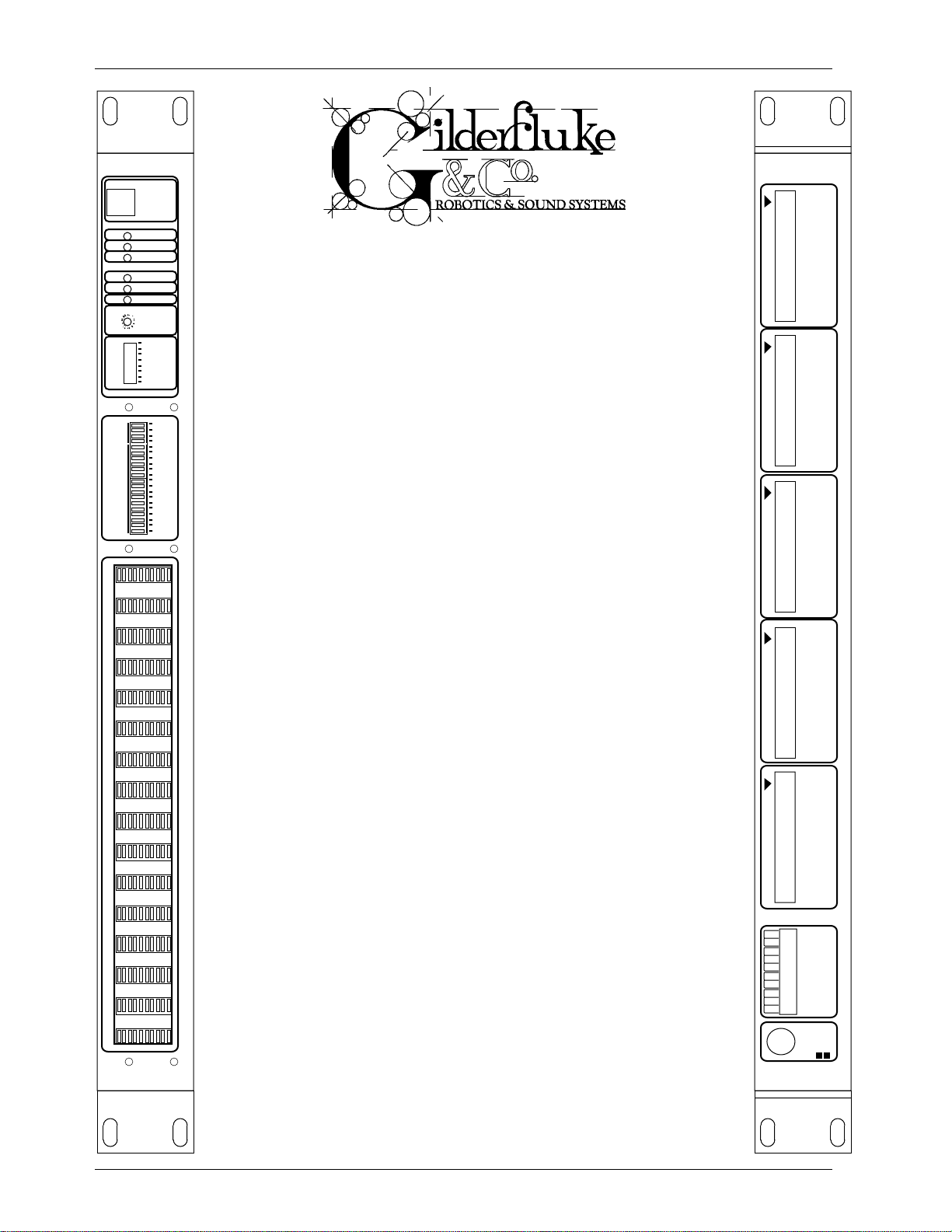
This is an Animation system with 128 digital outputs and (optionally) sixteen 0-10 VDC analog outputs. It can be used in standalone applications using its on-board EPROM or an external
Frequency Shift Keyed (FSK) /
Remote Terminal Unit (RTU)
Preliminary Printed February 27, 1999
Channels 0-3
J-6 Digital Outputs
source of FSK data for program storage. This unit can also be
Channels 4-7
J-6 Digital Outputs
Channels 8-B
J-6 Digital Outputs
fuses
Analog Outputs
0123456
F
E
3
used as an output device attached to a PC•MACs animation sys-
2
1
0
F
tem, receiving data sent to it through the DMX-512 or FSK inputs.
E
D
C
B
A
9
The FSK/RTU can be mounted in 1-3/4” of standard 19” rack
8
7
6
5
space. It requires 4-1/2 “ of space behind the panel. Power re-
4
3
2
1
quirements are between 12 and 24 VDC (18 VDC or greater if the
0
analog output option is installed). The current requirements are
FSK / REMOTE TERMINAL UNIT • GILDERFLUKE & COMPANY • GLENDALE , CALIFORNIA
7
determined by the loads attached to the unit. The FSK/RTU unit it-
fuse
self draws between 350 ma. and 1 amp, depending on the
fuse
number of front panel LEDs on at any one time.
D
fuse
This Animation System is used in one or more of the following three
C
B
A
9
8
7
6
5
4
3
2
1
0
0123456
fuse
modes:
fuse
1) Frequency Shift Keyed (FSK) Data Playback: To play animated shows
which have been recorded on any standard audio tape, Compact Disc,
fuse
LaserDisk, or other source of audio data. Sixteen to thirty-two 8 bit channels
of data can be played back using this unit. FSK data is normally generated
fuse
using a PC•MACs Animation Control System. When operating in this mode,
fuse
three relay outputs and/or the serial port can be used to start, stop and
rewind a tape deck, LaserDisk or Compact Disc players. Delays between
fuse
shows can be set for up to 9,999 seconds.
fuse
2) Remote Terminal Unit (RTU): Receive DMX-512 data transmitted by a
PC•MACs animation Control System, or any other source of DMX-512 data,
fuse
and convert it to individual digital outputs and (optionally) sixteen 0-10 volt
fuse
analog outputs. FSK/RTUs can be used to temporarily take the place of Brick
Animation Control Systems when programming a show from a PC•MACs sys-
fuse
tem. A single DMX-512 twisted pair is often more convenient to handle than
a multitude of temporary J6 ribbon cables.
fuse
3) Stand-Alone Animation Playback: A sequencer feature allows the unit
fuse
to play a show from an on-board EPROM memory. The FSK/RTU can be set to
play whenever either of the two data sources above stops. This allows an ani-
fuse
7
mated show to continue running in an ‘attract’ or ‘keep alive’ mode when it
isn’t playing any of the regular shows. This mode of operation can also be
used if you just need to run a single show continuously. The sequencer
EPROM is programmed using a PC•MACs Animation Control System.
Channels C-F
J-6 Digital Outputs
Channels 0-F
J-6/A Analog Outputs
gnd
pwr.
stop
stop
play
play
rew.
rew.
dmx-
dmx+
Input
3950 / 7150
FSK Data
FSK / REMOTE TERMINAL UNIT • GILDERFLUKE & COMPANY • GLENDALE , CALIFORNIA
9375 / 12,500
i of iii
Page 2

GILDERFLUKE & CO. • 205 SOUTH FLOWER ST. • BURBANK, CALIF. 91502-2102 • 818/840-9484 • FAX818/840-9485
ii of iii
Page 3

GILDERFLUKE & CO. • 205 SOUTH FLOWER ST. • BURBANK, CALIF. 91502-2102 • 818/840-9484 • FAX818/840-9485
Front of the FSK/RTU ............................................................................... 1
Eight Position Dipswitch ......................................................................................................... 1
Sixteen Position Rotary Switch ................................................................................................. 1
Six LEDs Indicate .................................................................................................................. 2
RS-422 Port .......................................................................................................................... 2
LED Indicators ...................................................................................................................... 2
On the back side of the FSK/RTU .............................................................. 2
Power Supply ...................................................................................................................... 2
Tape Deck Control ................................................................................................................ 2
Frequency Shift Keyed (FSK) Data Input .................................................................................... 2
DMX-512 Data Input ............................................................................................................. 2
Four J-6 connectors for Digital Data Output ............................................................................... 3
J6/A Analog Data Output (optional) ......................................................................................... 5
Frequency Shift Keyed (FSK) Tape (or Disk) Organization ............................................................. 8
FSK/RTU CONFIGURATION ........................................................................ 9
PC and Compatible Connections .......................................................................................... 10
Main Configuration Screens ................................................................................................. 11
Tape deck pulse- ....................................................................................................... 12
FSK/DMX dropout- ...................................................................................................... 12
FSK intershow- ........................................................................................................... 12
FSK startup- ............................................................................................................... 12
Minimum rewind- ....................................................................................................... 12
Set FSK time delays- ................................................................................................... 12
Enter strings- .............................................................................................................. 12
Sequencer enabled- ................................................................................................. 12
Countdown displayed- .............................................................................................. 12
Force digital outputs on- ............................................................................................ 13
Force digital outputs off- ............................................................................................ 13
Force analog to a value- ........................................................................................... 13
Set analog endpoints- ............................................................................................... 13
Download configuration- ........................................................................................... 13
Upload configuration- ................................................................................................ 13
Default configuration- ............................................................................................... 13
Read configuration from EEPROM- ............................................................................. 13
Write configuration to EEPROM- .................................................................................. 13
eXit- .......................................................................................................................... 13
Summary of Setup Commands ............................................................................................. 14
String Setup ....................................................................................................................... 15
String Setup Screen ............................................................................................................. 15
Special String Characters .......................................................................................... 16
ASCII Characters to be Sent Out ................................................................................ 17
ASCII Characters to be Recieved ............................................................................... 18
PIONEER LaserDisk COMMANDS ............................................................. 19
SONY LaserDisk COMMANDS .................................................................. 22
DECIMAL to HEXadecimal to ASCII to PERCENTAGE .................................... 25
iii of iii
Page 4

GILDERFLUKE & CO. • 205 SOUTH FLOWER ST. • BURBANK, CALIF. 91502-2102 • 818/840-9484 • FAX818/840-9485
iv of iv
Page 5

GILDERFLUKE & CO. • 205 SOUTH FLOWER ST. • BURBANK, CALIF. 91502-2102 • 818/840-9484 • FAX818/840-9485
On the Front of the FSK/RTU are:
A) Eight Position Dipswitch which is used as follows:
1) Initiate output test #1 when ON. Chases one digital output on at a time.
2) Initiate output test #2 when ON. Chases all digital outputs in a sweeping pattern.
3) Initiate output test #3 when ON. Spells out a difficult to read message on the digital
outputs.
4) When ON, data sent to the sixteen digital output channels is also mirrored to the optional analog outputs.
5) Use DMX-512 input rather than FSK input when ON. The Sixteen Position Rotary Switch
must be used to select the channels which the FSK/RTU will decode.
6) Depending on condition of switch #5:
a) If using FSK data input (switch #5 OFF): If ON, this switch is used to select the
higher frequency set. These allow up to 32 channels of data at 15 Frames per
Second or up to 16 channels of data at 30 Frames Per Second in the FSK data
stream. The FSK input section must be modified at the factory to support this
mode of operation. To generate FSK data in the proper format for this higher
speed, you must set the FSK data options for the 9375 Hz/12500 Hz option
with 16/32 channels set as appropriate (16 channels if the frame rate is 30
FPS / 32 channels if the frame rate is set to 15 FPS).
b) If using DMX-512 data input (switch #5 ON): If ON, tells FSK/RTU unit to use
checksum found in bytes 256 and 257 to verify DMX-512 data is valid before
updating outputs. This option is recommended for all DMX applications
7) If using higher frequency FSK data (switch #5 is OFF and switch #6 is ON), expect 32
channels at a 15 Frames Per Second rate when ON. When OFF, expect 16 channels
of data at a 30 Frames per Second rate. To generate FSK data in the proper format
for 32 channels of data, you must set the FSK data options for the 9375 Hz/12500 Hz
option with 32 channels of data. The show must be set for a frame rate of 15 Frames
Per Second.
8) Depending on condition of switch #5:
a1) When using high speed FSK data (switch #5 OFF, AND switch #6 ON), this tells
the RTU/FSK to look for a BREAK character to synchronize with the FSK data (instead of a value of 0A5h). To use this option, the PC•MACs SMPTE card must
be set to generate data in the same format. To do this, turn on dipswitch #6
on the SMPTE card2and set the FSK data options for the 9375 Hz/12500 Hz option with 16/32 channels set as appropriate (16 channels if the frame rate is
30 FPS / 32 channels if the frame rate is set to 15 FPS).
b) When using DMX-512 data input (switch #5 is ON), this option offsets the out-
puts by 256 channels into the data received. This is used to access DMX-512
channels 256 through 512.
B) Sixteen Position Rotary Switch. Depending on condition of switch #5:
a) If using DMX-512 data input (switch #5 ON): This switch is used to select which chan-
nels of DMX-512 data will be used by the FSK/RTU Unit. DMX-512 addresses are set in
HEX numbers, using this switch to select the upper digit. Normally channels 0 through
255 are selected (00h through FFh). If Dipswitch #8 is turned on, then DMX- addresses 256 through 511 can be selected (100h through 1FFh).
b) If using FSK data input (switch #5 OFF): This switch selects which delay between shows
is to be used. Sixteen different delay values can be set through the serial port, any of
which can be any length of time ranging from none to 9,999 seconds.
1
This option is availible on RTU/FSK firmware revision 2.10 and later only.
2
This option is availible on SMPTE card firmware revision 1.9 and later only.
1 of 25
Page 6

GILDERFLUKE & CO. • 205 SOUTH FLOWER ST. • BURBANK, CALIF. 91502-2102 • 818/840-9484 • FAX818/840-9485
C) Six LEDs Indicate:
1) Heartbeat: Flashes continuously while the CPU is running. If it ever stops for more than
a second or so, the ‘Deadman’ circuit in the FSK/RTU unit will automatically reset the
CPU.
2) Data received: Turns on when valid data is received from the FSK or DMX-512 input as
appropriate).
3) Data errors: Flashes for a moment whenever an error is detected in the FSK or DMX512 input (as appropriate). When operating in the FSK mode, excessive data errors indicate that the tape is getting too worn to reliably play back a show. When sending a
string to a serially controlled device, it will flash when an unexpected character is received.
4) Stop relay output activated: Lights when this tape deck control output is activated.
5) Play relay output activated: Lights when this tape deck control output is activated.
6) Rewind relay output activated: Lights when this tape deck control output is activated.
D) RS-422 Port used for accessing and modifying configuration of the FSK/DMX unit and for
sending commands to serially controlled devices like LaserDisk and Compact Disc players.
E) LED Indicators for all Digital, Analog and Fuse outputs (Optional).
On the back side of the FSK/RTU are connectors for:
A) Power Supply: The power supply input is used to feed a voltage between 12 and 24 Volts
Direct Current (VDC) to the FSK/DMX Unit. The voltage input must be 18 volts or greater if the
analog output option is installed.
The size and voltage of the power supply is determined by the load you are connecting to
it. In most cases a power supply in the 100 to 200 Watt range will be sufficient to drive most
shows. The polarity of these connections is plainly marked. The RTU/FSK unit itself draws about
350 ma. at 24 volts. With all of the indicator LEDs on the front of the unit, this can get as high
as 1 amp.
B) Tape Deck Control: These provide three normally open contact closures which can be con-
nected to the remote control inputs on a tape deck (or Compact Disc, LaserDisk player or
other audio source if you aren’t going to control it through its serial port).
The 'Play', ‘Rewind’ and 'Stop' outputs normally go the the 'Play', ‘Rewind’ and 'Stop' inputs
on a tape deck. As the system doesn't support a foil sensor input, the tape deck must be able
to take care of itself when it is given a rewind command. Since a cassette tape can't ever
come off the end of the reel, any cassette deck with remote control inputs will work. An open
reel tape deck can be used if it has a 'Home' function which can be attached to the 'Rewind'
output on the FSK/RTU. This will tell the tape deck to rewind and stop at the zero point set on
the tape counter.
C) Frequency Shift Keyed (FSK) Data Input: If FSK data is used, the FSK Data input is attached to
wherever it is coming from. This is usually the output of the data track on a tape deck,
Compact Disc or LaserDisk player. The FSK/RTU decodes the FSK data input and sends it to the
outputs. The standard FSK data rate sends out sixteen channels of data at fifteen frames per
second. At the higher FSK data rate (FSK/RTU must be factory modified to support this option),
data is limited to fifteen frames per second if transmitting thirty-two channels of data, or thirty
frames per second if transmitting sixteen channels of data.
D) DMX-512 Data Input: The DMX-512 standard was developed by the United States Institute for
Theatrical Technology (USITT) for a high speed (250 KBaud asynchronous) serial link. Although it
was originally designed for controlling light dimmers, it is now supported by hundreds of suppliers throughout the world for controlling all kinds of theatrical equipment.
Even though the DMX-512 standard calls for 512 channels of data, the DMX transmission
from PC•MACs is limited to 256 eight bit wide channels. You can address the FSK/RTU to respond to any address between 00 and 512. Addresses above the 256th are used in PC•MACs
2 of 25
Page 7
k
GILDERFLUKE & CO. • 205 SOUTH FLOWER ST. • BURBANK, CALIF. 91502-2102 • 818/840-9484 • FAX818/840-9485
for transmitting a checksum. The FSK/RTU can use this to verify that the data received from
PC•MACs has no transmission errors in it. If you address a FSK/RTU or other DMX-512 device to
addresses 256 or 257, you will see this verification data displayed as a flickering pattern. Note
that at frame rates higher than 40 FPS, not all 256 channels will be transmitted through the
DMX-512 output.
The positive and negative DMX-512 wires are attached to the FSK/RTU through the screw
terminals marked on its back. The shield (if any) can be attached to the ground side of the
power supply terminal.
E) Four J-6 connectors for Digital Data Output: In all the animation systems made by
Gilderfluke & Company, all digital input and output cabling is through what we call ‘J6’ standard output cables. These are 40 wire cables which are made up of four identical eight bit
wide ‘channels’. A J6 cable is often split up into four individual channels. Each ‘1/4 J6’ cable is
made up of 10 wires, and can be used to control eight individual ‘digital’ (off/on) devices, or
one eight bit wide ‘analog’ device. The remaining two wires in each 1/4 J6 are used for
ground and a power connection.
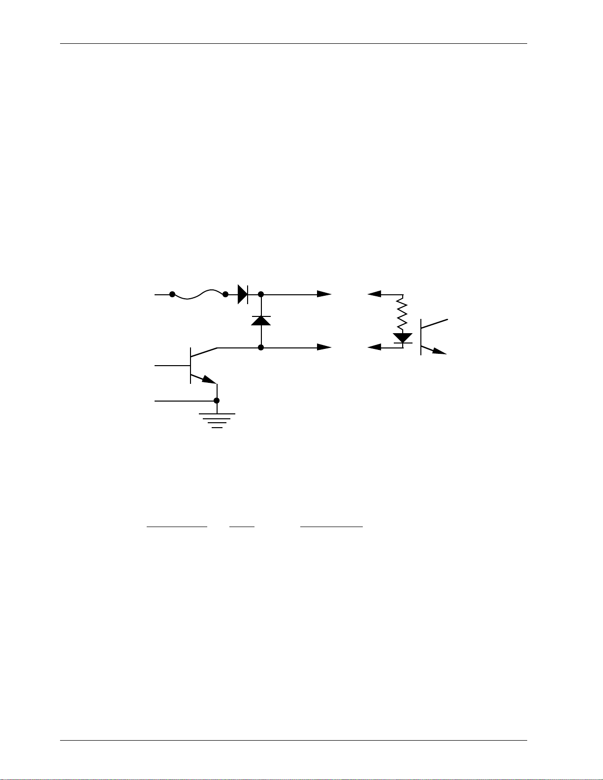
In all the animation systems made by Gilderfluke & Company, all digital outputs are open
collector switches to ground, and all digital inputs are through optoisolators. Flyback diodes
are included in the outputs for driving inductive loads:
fuse
flybac
supply supply
diode
typical output
typical input
To simplify wiring to any of our animation systems, the connectors used on the J6 cables
are what are called ‘insulation displacement connectors’. These simply snap on to an entire
cable, automatically ‘displacing’ the wire insulation and making contact with the wires within.
This means that an entire 40 wire cable can be terminated in seconds. All connectors are polarized, to keep them from being plugged in backwards.
Each J6 cable is arranged in the following order:
wire number color wire function
1 brown circuit ground
2 red channel 0 data bit 7
3 orange channel 0 data bit 6
4 yellow channel 0 data bit 5
5 green channel 0 data bit 4
6 blue channel 0 data bit 3
7 violet channel 0 data bit 2
8 gray channel 0 data bit 1
9 white channel 0 data bit 0
10 black + unregulated power supply (protected to 1 amp)
11 brown circuit ground
12 red channel 1 data bit 7
13 orange channel 1 data bit 6
14 yellow channel 1 data bit 5
15 green channel 1 data bit 4
16 blue channel 1 data bit 3
3 of 25
Page 8
d
d
#
#
#
#
#
-
GILDERFLUKE & CO. • 205 SOUTH FLOWER ST. • BURBANK, CALIF. 91502-2102 • 818/840-9484 • FAX818/840-9485
17 violet channel 1 data bit 2
18 gray channel 1 data bit 1
19 white channel 1 data bit 0
20 black + unregulated power supply (protected to 1 amp)
21 brown circuit ground
22 red channel 2 data bit 7
23 orange channel 2 data bit 6
24 yellow channel 2 data bit 5
25 green channel 2 data bit 4
26 blue channel 2 data bit 3
27 violet channel 2 data bit 2
28 gray channel 2 data bit 1
29 white channel 2 data bit 0
30 black + unregulated power supply (protected to 1 amp)
31 brown circuit ground
32 red channel 3 data bit 7
33 orange channel 3 data bit 6
34 yellow channel 3 data bit 5
35 green channel 3 data bit 4
36 blue channel 3 data bit 3
37 violet channel 3 data bit 2
38 gray channel 3 data bit 1
39 white channel 3 data bit 0
40 black + unregulated power supply (protected to 1 amp)
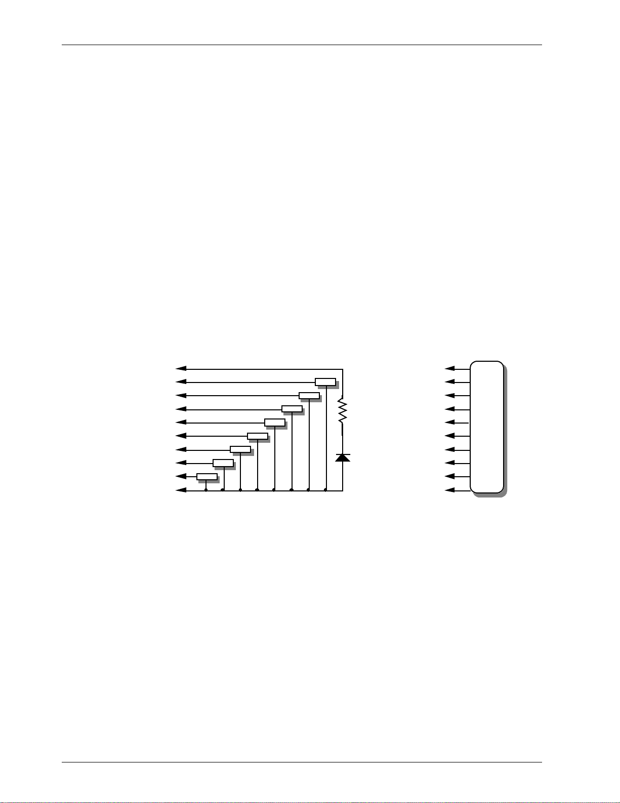
#1 ground (brown)--
#2 bit 7 (red)--
#3 bit 6 (orange)--
#4 bit 5 (yellow)--
#5 bit 4 (green)--
#6 bit 3 (blue)--
#7 bit 2 (violet)--
#8 bit 1 (grey)--
#9 bit 0 (white)--
#10 supply (black)--
loa
load
load
load
loa
load
load
load
LED
#1 ground (brown)--
2.2 K ohm
1/4 watt resistor
#10 supply (black)-
2 bit 7 (red)--
#3 bit 6 (orange)--
4 bit 5 (yellow)--
#5 bit 4 (green)--
6 bit 3 (blue)-7 bit 2 (violet)-#8 bit 1 (grey)--
9 bit 0 (white)--
any
eight bit
analog
device
Any eight digital devices or one eight bit analog device can be connected to any 1/4 J6
cable as shown. The LED between the ground (pin #1 brown) wire and supply (pin #10 black)
wire acts as an indicator which is lit if the fuse for that channel is OK.
The supply line for each 1/4 J6 is protected by a solid state circuit breaker (PTC Fuse) for 1
amp. You should treat each 1/4 J6 as an individual, and not cross the outputs or supply lines
from one 1/4 J6 to the lines from another. Doing this won’t cause any damage, but can reduce the protection for the outputs that the circuit breakers normally provide.
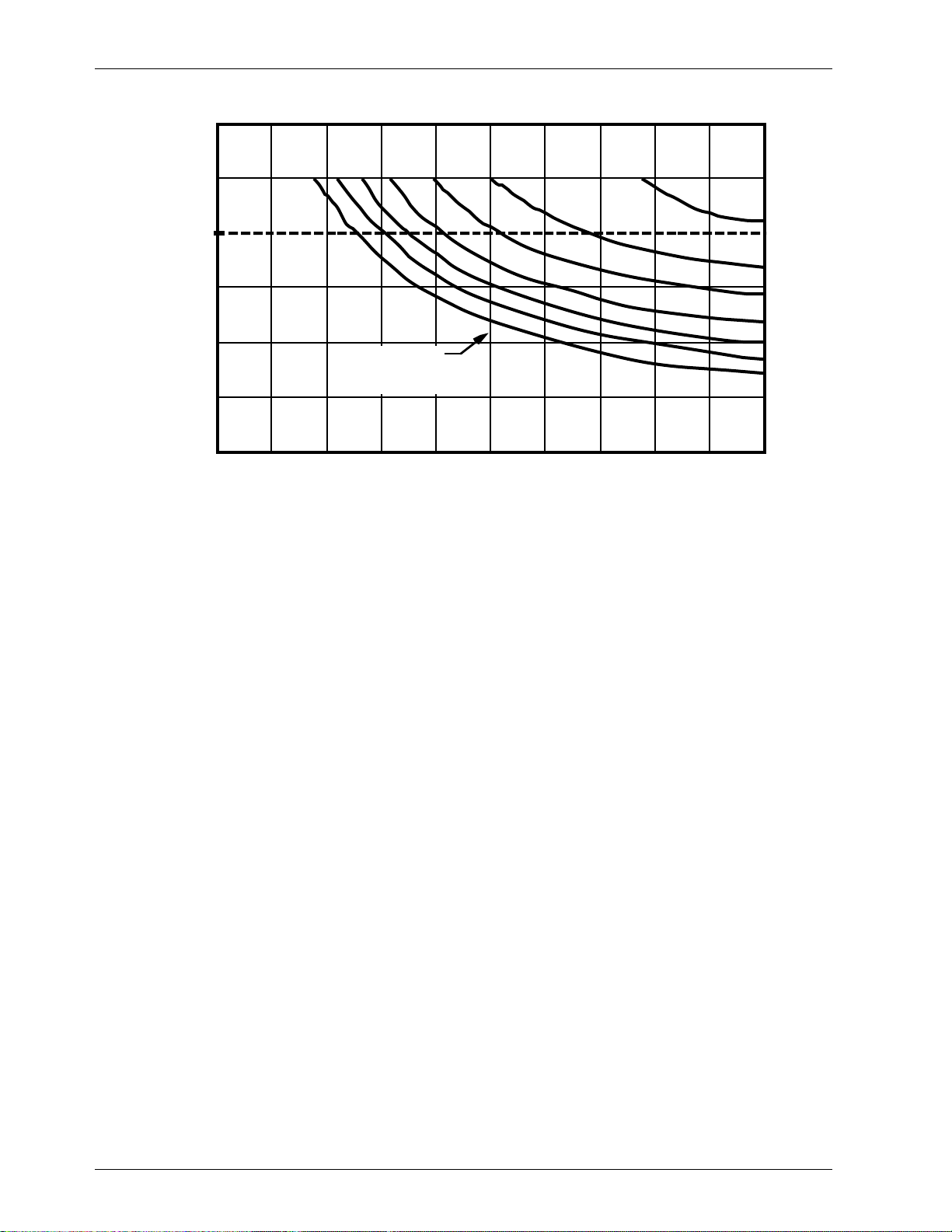
The current output capacity of each output is as shown in the following chart:
4 of 25
Page 9
GILDERFLUKE & CO. • 205 SOUTH FLOWER ST. • BURBANK, CALIF. 91502-2102 • 818/840-9484 • FAX818/840-9485
PEAK COLLECTOR CURRENT
AS A FUNCTION OF DUTY CYCLE
600
500
2
400
300
200
100
ALLOWABLE PEAK COLLECTOR CURRENT IN mA AT 70ºC
0
10 20 30 40 50 60 70 80 90 100
NUMBER OF OUTPUTS
CONDUCTING
SIMULTANEOUSLY
7
8
PER CENT DUTY CYCLE
5
6
3
4
Since it is unusual to have more than 50% of the outputs on at any one time, you can
usually assume the system has a 250 ma output current capacity. If you are going to be turning on lots of heavy loads at the same time, you should derate this to 150 ma.. This is sufficient to drive the majority of loads that will be directly connected to the outputs of the animation system. FSK/RTUs use a Micrel MIC58P01CN output driver chip. These chips add output
protection to each individual output which acts much like an electronic circuit breaker. When
the rated output of a chip is exceeded, it will turn ‘OFF’. To reset the output, just temporarily
power down the FSK/RTU.
If additional current capacity is needed, or if you need to drive higher voltage loads, you
can connect relays as needed to the outputs of the animation system. Coincidentally, boards
for doing this are available from Gilderfluke & Company. These include:
Solid State Output Drivers: These snap track mounted cards each have eight optoisolated outputs. Current capacities available range from 700 ma. up to 3.5 amps. The
lower current models are internally protected.
DPDT relay board: A set of eight electromechanical relays with double pole/double
throw contacts rated at 5 amps each.
Reed relay board: A set of eight small electromechanical relays with normally open
contacts rated at 150 ma each.
I/O module: A set of eight small solid state relays with normally open contacts rated at
3.5 amps each (AC and DC relays available).
Solid State Relay Fanning Strip: For connecting up to eight popular ‘hockey puck’
style relays to a 1/4 J-6 output cable. These are available with capacities of up to 75
amps each.
F) One J6/A Analog Data Output (optional) : In all the animation systems made by Gilderfluke &
Company, all Analog input and output cabling is through what we call ‘J6/A’ standard output
cables. These are 40 wire cables which are made up of four identical four channel wide cables. A J6/A cable is often split up into four individual cables called a 1/4 J6/A. Each 1/4 J6/A
also includes a common power supply and ground wire which allow it to provide power for
analog output accessories like Electronic FeedBack (EFB) controllers and 16 Channel Servo
Controllers.
To simplify wiring to any MACs animation system, the connectors used on the J6/A cables
5 of 25
Page 10

GILDERFLUKE & CO. • 205 SOUTH FLOWER ST. • BURBANK, CALIF. 91502-2102 • 818/840-9484 • FAX818/840-9485
are what are called ‘insulation displacement connectors’. These simply snap on to an entire
cable, automatically ‘displacing’ the wire insulation and making contact with the wires within.
This means that an entire 40 wire cable can be terminated in seconds. All connectors are polarized, to keep them from being plugged in backwards.
Each J6/A cable is arranged in the following order:
wire number color wire function
1 brown circuit ground
2 red + unregulated power supply (protected to 1 amp)
3 orange Output 15 (0Fh) Positive Analog Output
4 yellow Output 15 (0Fh) Negative Reference
5 green Output 14 (0Eh) Positive Analog Output
6 blue Output 14 (0Eh) Negative Reference
7 violet Output 13 (0Dh) Positive Analog Output
8 gray Output 13 (0Dh) Negative Reference
9 white Output 12 (0Ch) Positive Analog Output
10 black Output 12 (0Ch) Negative Reference
11 brown circuit ground
12 red + unregulated power supply (protected to 1 amp)
13 orange Output 11 (0Bh) Positive Analog Output
14 yellow Output 11 (0Bh) Negative Reference
15 green Output 10 (0Ah) Positive Analog Output
16 blue Output 10 (0Ah) Negative Reference
17 violet Output 9 (09h) Positive Analog Output
18 gray Output 9 (09h) Negative Reference
19 white Output 8 (08h) Positive Analog Output
20 black Output 8 (08h) Negative Reference
21 brown circuit ground
22 red + unregulated power supply (protected to 1 amp)
23 orange Output 7 (07h) Positive Analog Output
24 yellow Output 7 (07h) Negative Reference
25 green Output 6 (06h) Positive Analog Output
26 blue Output 6 (06h) Negative Reference
27 violet Output 5 (05h) Positive Analog Output
28 gray Output 5 (05h) Negative Reference
29 white Output 4 (04h) Positive Analog Output
30 black Output 4 (04h) Negative Reference
31 brown circuit ground
32 red + unregulated power supply (protected to 1 amp)
33 orange Output 3 (03h) Positive Analog Output
34 yellow Output 3 (03h) Negative Reference
35 green Output 2 (02h) Positive Analog Output
36 blue Output 2 (02h) Negative Reference
37 violet Output 1 (01h) Positive Analog Output
38 gray Output 1 (01h) Negative Reference
39 white Output 0 (00h) Positive Analog Output
40 black Output 0 (00h) Negative Reference
Analog loads are connected between each of the Positive outputs and its associated
Negative reference. The output capacity of each output is 20 ma. The output voltage range
can be adjusted from the FSK/RTU to anywhere between 0 and 10 volts. Current amplifiers are
available if additional current capacity is required for your application.
The negative reference is at a voltage of approximately 1.6 volts above the circuit ground.
The negative references are all connected on the FSK/RTU, but there must be no direct con-
nections made between any of the negative references and the circuit grounds anywhere
in the animation system.
6 of 25
Page 11

GILDERFLUKE & CO. • 205 SOUTH FLOWER ST. • BURBANK, CALIF. 91502-2102 • 818/840-9484 • FAX818/840-9485
The supply line for each 1/4 J6/A is protected by a solid state circuit breaker (PTC Fuse)
rated for 1 amp. You should treat each 1/4 J6/A as an individual, and not cross the outputs or
supply lines from one 1/4 J6/A to the lines from another. Doing this won’t cause any damage,
but can reduce the protection for the outputs that the circuit breakers normally provide. A LED
and resistor on each 1/4 J6/A between the ground (pin #1 brown) wire and supply (pin #2
red) wire can act as an indicator which is lit if the circuit breaker is OK. The resistor should be a
value between 2.2 Kohms and 4.7 Kohms.
There is one adjustment on the FSK/RTU for setting the maximum analog voltage to be output. This sets the gain for the Digital to Analog (D/A) converters on the board. To set it, pick any
output and set the minimum and maximum scaling to their minimums and maximums through
the configuration screen. When you send a full scale output command to this output, you
should then be able to adjust it for 10.00 volts using R11. The adjustments for the endpoints
on each of the 16 outputs are normally individually set through the setup screen software.
7 of 25
Page 12

GILDERFLUKE & CO. • 205 SOUTH FLOWER ST. • BURBANK, CALIF. 91502-2102 • 818/840-9484 • FAX818/840-9485
Frequency Shift Keyed (FSK) Tape (or Disk) Organization:
When operating in FSK mode, the system is constantly listening for data on the FSK input. Whenever it
hears valid data, it will start decoding it and sending it to the outputs. This means that a show can be started at any time by simply pressing the 'Play' button on the tape deck (or LaserDisk or Compact Disc player)
that supplies the FSK data.
Since it will play whenever it hears FSK data, a show which is run from a loop deck or other continuous
source of FSK data will play continuously.
The FSK/RTU doesn't use any codes embedded in the FSK data or sensors on the FSK source to find
where it is. When it sends a PLAY string (usually starting the tape deck, Compact Disc or LaserDisk player), it
starts the ‘FSK startup’ timer. If it finds FSK data before the ‘FSK startup’ timer expires, then it is off and running. If it doesn't hear any FSK data before the ‘FSK startup’ time, then it assumes that the tape is positioned incorrectly and so starts a rewind sequence and a new delay between shows.
Once the system has started playing, it ignores any gap in the data of less than what has been set for
the ‘FSK/DMX dropout’ time. If it finds a gap of more than this time, then it assumes that it has just found
the end of a show. It won't send the STOP string yet, but instead will start looking for the FSK data to pick
back up at the start of the next show. If it receives FSK data again before the ‘FSK Intershow’ timer expires,
it will send the STOP string (usually stopping the tape deck or other source of FSK data), and start the
countdown delay for the next show. If no next show is found within the time set for the ‘FSK Intershow’
timer, then it assumes that this was the last show on the tape (or disk) and will initiate a rewind sequence.
The format for the tape or disk) must be as follows:
1) Start of tape (or disk).
2) Gap of less than the time set for the ‘startup timer’ before first show’s FSK data starts (the shorter the better).
3) Show number 1.
4) Gap in the FSK data between shows which is longer than the time set for the ‘FSK/DMX
dropout’ timer, but shorter than the length set for the ‘FSK Intershow’ timer. The FSK/RTU will
send out the STOP string and start a new countdown between shows when the FSK data starts
again.
5) Repeat numbers 3 and 4 above for each show on tape (or disk).
6) Last show on tape (or disk).
7) Gap in the FSK data which is longer than the time set for the ‘FSK Intershow’ timer. This will initiate a tape rewind sequence.
When operating from a Compact Disc or LaserDisk, the REWIND string is used to position the disk to the
start of the first show. This makes it the most complex of the three possible strings.
If you would like a show to play continuously from a Compact Disc or LaserDisk, the PLAY string can
send a string to the player which tells it to play the same show over and over again.
On systems that use tape decks, the delay between shows can be shorter than the time it takes to fully
rewind the tape. If the delay time is not longer, then the system can try to start playing at wherever the
tape happens to be when the countdown ends. If the ‘normal’ delay is shorter than the ‘minimum rewind’
time, the ‘minimum rewind’ timer will automatically be used instead.
8 of 25
Page 13

GILDERFLUKE & CO. • 205 SOUTH FLOWER ST. • BURBANK, CALIF. 91502-2102 • 818/840-9484 • FAX818/840-9485
FSK/RTU CONFIGURATION:
All commands sent to the FSK/RTU Unit through its serial interface take the following format. All characters are sent in ASCII. All numeric values are sent in HEXadecimal (HEX for short), and consist of one or
more ASCII characters (0-9, A through F). The case (as in upper and lower) of all input is important. A lower
case 'a' signifies a command, while an 'A' is a numeric value. If the FSK/RTU Unit receives another command while it is waiting for additional input needed to complete the previous command, it will abandon
the previous command and start working on the new one.
To communicate with the FSK/RTU Unit through the serial port, you can use just about any computer or
terminal which has a serial port on it. Some newer computer designs, like the Apple Macintosh, come with
serial ports which are directly compatible with the RS-422 / RS-485 signal levels the FSK/RTU Unit wants to
see. These signal levels are close enough to be used with the RS-232 signal levels found on most older
computers (like most IBMs and compatibles) with only a simple adapter cable, so long as the wire isn't too
long. To gain the full advantage of the RS-422 / RS-485 signal levels you will need to use a signal level
adapter like our 232conv-09.
If you are using a computer as a terminal you will need to run a modem or terminal emulation program. These will send everything you type on the keyboard out the serial port on your computer while
printing on the screen anything which comes in from the FSK/RTU Unit through the serial port. Every copy
of Windows comes with TERM.EXE, which is just such a program. A modem program will usually have the
advantage over a terminal emulation program in that it will allow you to save data to your computer's disk
drives and then send it back to the FSK/RTU Unit at a later date. The FSK/RTU Unit uses no screen control
codes or ESCape sequences, so it should work on any machine with an 80 column by 24 line display.
Machines with other display formats will work, but may not look so neat on the screen.
When configuring your modem program, you should set it for 9600 baud, 8 data bits, one stop bit,
and no parity. Higher or lower baud rates can be used if you configure the FSK/RTU Units’ serial port to run
at a different speed. You should set your program not to insert an extra LineFeed (LF) character after each
Carriage Return (CR) it receives. If you are going to be downloading configuration strings to the system
(command ‘s’), you will also need to tell the modem program to put a slight delay between each character sent in order to not over run the FSK/RTU Unit’s incoming data buffer.
If you have hooked up the FSK/RTU Unit to your computer and it still doesn’t seem to respond to the
keyboard, the first thing to check is that you are attached to the right serial port. The easiest way to do this
is to disconnect the FSK/RTU Unit and short between the Tx data out and Rx data in pins on the serial port
connector on the back of your computer. On all IBMs and compatibles this means sticking a paper clip or
similar tool between pins 2 and 3 on the ‘Com.’ connector. While still running the modem program, anything you type should be shown on the screen while this paper clip is in place, while nothing will appear
when you remove it. If your computer passes this test, then you are using the right serial port and the
problem is most likely the baud rate setting or in your wiring to the FSK/RTU Unit. If you get characters on
the screen even with the paper clip removed from the serial port, it means you probably need to set the
‘echo’ mode to ‘none’ or ‘full duplex’ and try this test again.
The serial data signals from the FSK/RTU Unit are brought out on a 6 position RJ-11 (modular telephone
style connector). Facing the end of the cable with the release latch upwards, its pin out is as follows:
9 of 25
Page 14

GILDERFLUKE & CO. • 205 SOUTH FLOWER ST. • BURBANK, CALIF. 91502-2102 • 818/840-9484 • FAX818/840-9485
COLOR SIGNAL NAME:
LEFT WHITE SIGNAL GROUND
BLACK - SERIAL DATA OUT FROM FSK/RTU Unit
RED + SERIAL DATA OUT FROM FSK/RTU Unit
GREEN - SERIAL DATA IN TO REPEATERS
YELLOW + SERIAL DATA IN TO REPEATERS
RIGHT BLUE SIGNAL GROUND
PC and Compatible Connections: To cross wire the RS-422 / RS-485 signals from the FSK/RTU Unit to
the RS-232 serial port of an IBM compatible, cross connect the signals as follows:
DB-25 DE-9 SIGNAL SIGNAL FROM/TO FSK/RTU Unit
2 3 DATA OUT - SERIAL DATA IN TO FSK/RTU Unit (GREEN)
3 2 DATA IN - SERIAL DATA OUT FROM FSK/RTU Unit (BLACK)
7 5 GROUND SIGNAL GROUND (BLUE or WHITE)
Apple Macintosh computers have true RS-422 serial ports built in. To connect to the Smart Brick
System, the pin out is as follows for a Macintosh mini-DIN-8:
to + serial data in to card (#5 yellow)
to - serial data in to card (#4 green)
signal ground (#1 blue or #6 white)
The FSK/RTU Unit expects to see the serial data in the following format:
678
345
12
from + serial data out from card (#3 red)
from - serial data out from card (#2 black)
ONE START BIT
EIGHT DATA BITS
ONE or TWO STOP BITS
Unlike many of the products manufactured by Gilderfluke & Company, the FSK/RTU can not share the
serial port with other devices at the same time. The screen is displayed when you enter:
m5AA5
To redraw the screen at any time, just press the <ESC>ape key. If the FSK/RTU is set for FSK data, then
the following screen will be displayed:
10 of 25
Page 15

GILDERFLUKE & CO. • 205 SOUTH FLOWER ST. • BURBANK, CALIF. 91502-2102 • 818/840-9484 • FAX818/840-9485
Main Configuration Screens:
-Gilderfluke & Company - RTU/FSK Controller - version 2.00 - copyright 1994 DCM-
sequencer = 20h x 06450 frames forced forced forced analog analog delay
ON OFF analog min. max. seconds
a) tape deck pulse- 0.5 seconds 0:______|______|______|__00__|__FF__|__0000__|
b) FSK/DMX dropout- 1.0 seconds 1:______|______|______|__00__|__FF__|__0015__|
c) FSK intershow- 10 seconds 2:______|______|______|__00__|__FF__|__0030__|
d) FSK startup- 20 seconds 3:______|______|______|__00__|__FF__|__0045__|
e) minimum rewind- 0030 seconds 4:______|______|______|__00__|__FF__|__0060__|
f) set FSK time delays 5:______|______|______|__00__|__FF__|__0090__|
g) enter strings 6:______|______|______|__00__|__FF__|__0120__|
h) sequencer enabled- yes 7:______|______|______|__00__|__FF__|__0180__|
i) countdown displayed- yes 8:______|______|______|__00__|__FF__|__0240__|
j) force digital outputs off 9:______|______|______|__00__|__FF__|__0300__|
k) force digital outputs on A:______|______|______|__00__|__FF__|__0450__|
l) force analog to a value B:______|______|______|__00__|__FF__|__0600__|
n) set analog endpoints C:______|______|______|__00__|__FF__|__0900__|
r) download configuration D:______|______|______|__00__|__FF__|__1200__|
s) upload configuration E:______|______|______|__00__|__FF__|__1500__|
t) default configuration F:______|______|______|__00__|__FF__|__1800__|
u) Read configuration from EEPROM
w) Write configuration to EEPROM | x) eXit
countdown- 0000 | dropout timer- 00 | intershow timer- 00 | startup timer- 00
If the FSK/RTU is set for receiving DMX-512 data, the following menu will be displayed instead. It differs
from the first only in that several of the commands and settings which are specific to the FSK data have
been disabled.
-Gilderfluke & Company - RTU/FSK Controller - version 2.00 - copyright 1994 DCM-
sequencer = 20h x 06450 frames forced forced forced analog analog
ON OFF analog min. max.
0:______|______|______|__00__|__FF__|
b) FSK/DMX dropout- 1.0 seconds 1:______|______|______|__00__|__FF__|
2:______|______|______|__00__|__FF__|
3:______|______|______|__00__|__FF__|
4:______|______|______|__00__|__FF__|
5:______|______|______|__00__|__FF__|
6:______|______|______|__00__|__FF__|
h) sequencer enabled- yes 7:______|______|______|__00__|__FF__|
8:______|______|______|__00__|__FF__|
j) force digital outputs off 9:______|______|______|__00__|__FF__|
k) force digital outputs on A:______|______|______|__00__|__FF__|
l) force analog to a value B:______|______|______|__00__|__FF__|
n) set analog endpoints C:______|______|______|__00__|__FF__|
r) download configuration D:______|______|______|__00__|__FF__|
s) upload configuration E:______|______|______|__00__|__FF__|
t) default configuration F:______|______|______|__00__|__FF__|
u) Read configuration from EEPROM
w) Write configuration to EEPROM | x) eXit
command-
On either of these menus, the size of the sequencer EPROM installed (if any)is also shown near the top
of the screen. If the sequencer EPROM isn’t found, then this area will not appear on the screen.
If another command is entered while the last command is waiting for additional input, the new command will be started. If at any point you enter a command in error and it is waiting for additional input,
you can leave the command by entering an <ESC>ape key. You can also bail from the string entry com-
11 of 25
Page 16

GILDERFLUKE & CO. • 205 SOUTH FLOWER ST. • BURBANK, CALIF. 91502-2102 • 818/840-9484 • FAX818/840-9485
mands without having to enter all 80 characters. Doing so will conclude (not abort) the string entry commands. Al other commands are aborted by entering an <ESC>ape key.
If you want to keep a hard copy printout of the current configuration of the RTU/FSK, you should use
the <ESC>ape key to redraw the screen while saving the print in the modem program running on your
computer. This file can then be printed out at any time.
a) Tape deck pulse- This command is used to set how long (in 10ths of seconds) the relay clo-
sures sent to tape deck will remain closed. This command is used only in FSK mode.
b) FSK/DMX dropout- This command is used to set how long of a gap (in 10ths of seconds)is al-
lowed before the FSK/RTU assumes that the data has been well and truly lost. If running from
FSK data, this will start the ‘FSK Intershow’ timer when it runs out. If it is installed and enabled,
both FSK and DMX-512 controlled units will start outputting data from their on-board sequencer EPROM after this timer has expired.
c) FSK intershow- This command is used to set how long of a gap (in seconds)to allow between
shows on a tape. If FSK data from the next show on the tape is found before this timer expires,
the FSK/RTU will send out its STOP string and start the countdown to the next show. If this timer
does expire, then the FSK/RTU will send out its REWIND string and start the countdown to the
next show. This command is used only in FSK mode.
d) FSK startup- This command is used to set how long of a gap (in seconds)after sending a START
sequence to wait before receiving FSK data. If this timer expires, then a REWIND sequence will
be started and a new countdown to the next show will be initiated. This command is used only
in FSK mode.
e) Minimum rewind- Because the delay between shows can be shorter than the time the tape
deck requires to rewind the tape, this value (in seconds) will automatically be used for the
delay between shows after a rewind if it is larger than the currently selected delay. This command is used only in FSK mode.
f) Set FSK time delays- This command is used to set the sixteen possible different delays the
users can select from the rotary switch on the front of the FSK/RTU for the delays between
shows. Any delay between 0000 (none) and 9999 seconds can be used. This command is
used only in FSK mode.
g) Enter strings- STRINGS are the ASCII characters and commands which you can tell the
FSK/RTU to send at the start or end of any show through its serial port. The Strings used in the
FSK/RTU are similar to those used in PC•MACs or the Smart Brick Animation Control Systems.
They are used primarily to talk to LaserDisk and Compact Disc players or just to tell the FSK/RTU
to close the contacts on its tape deck control outputs. They can also be used to send commands through the serial port to any other piece of show equipment that needs a serial input
to start or stop it, or even just to print on a monitoring screen that a show has started or
ended.
When using the FSK/RTU with a LaserDisk or Compact Disc, you will typically use the STOP
string to pause the player, the PLAY string to tell the player to start playing, and the REWIND
string to spin up the disk and position the player to the beginning of the first show.
Please see the section on this manual on STRING SETUP for more details on their care and
feeding.
h) Sequencer enabled- This toggle is used to enable the sequencer EPROM, if it has been in-
stalled. When enabled, the show data stored in the sequencer EPROM will be played back as
long as there is no FSK or DMX-512 data being received. Valid frame rates are 15 or 30 frames
per second. The sequencer EPROM is programed using a PC•MACs Animation Control system
to program an appropriate animation sequence, which is then downloaded to a ‘multi’ EPROM
file using the ‘Save as EPROM....’ command under the file pulldown menu.
i) Countdown displayed- When this toggle is ‘ON’, the countdowns used when running FSK
based shows will be displayed on the bottom of the screen. This is useful for seeing how these
counters are working. As long as you are not using the serial port for controlling a LaserDisk or
Compact Disc player, you can go ahead and leave this toggle ‘ON’.
12 of 25
Page 17

GILDERFLUKE & CO. • 205 SOUTH FLOWER ST. • BURBANK, CALIF. 91502-2102 • 818/840-9484 • FAX818/840-9485
j) Force digital outputs on- This command is used to force any of the 128 digital outputs ‘ON’.
No matter where the data comes from, an output that has been forced on can not be turned
off.
k) Force digital outputs off- This command is used to force any of the 128 digital outputs ‘OFF’.
No matter where the data comes from, an output that has been forced off can not be turned
back on.
l) Force analog to a value- This command is used to force any of the analog outputs (if in-
stalled) to a set value. Once an analog output has been forced to a to a level, no matter
where data comes from it will not change.
n) Set analog endpoints- This command is used to adjust the endpoints of the 16 analog out-
puts (if installed). The analog outputs normally sweep between 0 and 10 Volts DC. By using
these commands you can set either endpoint to anywhere between 0 and 10 volts for a reduced or reversed analog output swing. If you want to invert the voltage swing of any output,
all you need to do is set the lower limit to a higher level than the upper limit.
As an example of the use of the analog endpoint adjustments, if you wanted to set the
voltages on a channel to sweep from 2.5 volts to 7.5 volts: Looking at the chart at the end of
this manual, you can see that this would be from approximately 25% to 75% of full scale.
From the chart you would see that the values that should be entered would be 40h and C0h.
r) Download configuration- This command is used to save the current configuration of the
FSK/RTU through the serial port to a file on your computer. This file can then be reloaded into
this, or any other FSK/RTU. To use this command, you first invoke it, then following the instructions, you set your computer to receive a string of ASCII characters. You then press any key to
tell the FSK/RTU to send out it’s configuration. When it has finished, you then tell your computer
to stop saving characters, and then hit any key to tell the FSK/RTU to redraw the screen.
s) Upload configuration- This command is the compliment of the previous command. To invoke
it, all you need to do is tell your modem program to send the file saved by the ‘download’
command to the FSK/RTU. This will automatically invoke the upload command and store the incoming data. The data won’t be saved permanently until you invoke the ‘Write configura-
tion to EEPROM’.
t) Default configuration- This command reloads the default configuration to the FSK/RTU.
u) Read configuration from EEPROM- This reads the permanently stored configuration into the
FSK/RTU’s memory from the EPROM. This configuration is normally loaded by the FSK/RTU only
at boot up. This command can be used if you have made some changes in the configuration
that you now want the FSK/RTU to forget.
w) Write configuration to EEPROM- This command is used to write any changes you have made
in the configuration to the permanent EEPROM memory in the FSK/RTU.
x) eXit- This exits the configuration mode and returns the FSK/RTU to the command mode.
13 of 25
Page 18

GILDERFLUKE & CO. • 205 SOUTH FLOWER ST. • BURBANK, CALIF. 91502-2102 • 818/840-9484 • FAX818/840-9485
Summary of Setup Commands:
a) tape deck pulse
b) FSK/DMX dropout
c) FSK intershow
d) FSK startup
e) Minimum rewind
f) Set FSK time delays
g) Enter strings
h) Sequencer enabled
i) Countdown displayed
j) Force digital outputs off
k) Force digital outputs on
l) Force analog to a value
n) Set analog endpoints
r) Download configuration
s) Upload configuration
t) Default configuration
u) Read configuration from EEPROM
w) Write configuration to EEPROM
x) eXit
14 of 25
Page 19

GILDERFLUKE & CO. • 205 SOUTH FLOWER ST. • BURBANK, CALIF. 91502-2102 • 818/840-9484 • FAX818/840-9485
- String Setup -
STRINGS are the ASCII characters and commands which you can tell the FSK/RTU send at the start or
end of any show through its serial port. The Strings used in the FSK/RTU are similar to those used in
PC•MACs or the Smart Brick Animation Control Systems. They are used primarily to talk to LaserDisk and
Compact Disc players or just to tell the FSK/RTU to close the contacts on its tape deck control outputs.
They can also be used to send commands through the serial port to any other piece of show equipment
that needs a serial input to start or stop it, or even just to print on a monitoring screen that a show has
started or ended.
When using the FSK/RTU with a LaserDisk or Compact Disc, you will typically use the STOP string to
pause the player, the PLAY string to tell the player to start playing, and the REWIND string to spin up the disk
position the player to the beginning of the first show.
The ‘enter string’ command leads to the following String Setup Screen (the default configuration is
shown):
-Gilderfluke & Company - RTU/FSK Controller - version 2.00 - copyright 1994 DCM-
a) Stop String:
05 00 00 00 00 00 00 00 00 00 00 00 00 00 00 00 ................
00 00 00 00 00 00 00 00 00 00 00 00 00 00 00 00 ................
00 00 00 00 00 00 00 00 00 00 00 00 00 00 00 00 ................
00 00 00 00 00 00 00 00 00 00 00 00 00 00 00 00 ................
00 00 00 00 00 00 00 00 00 00 00 00 00 00 00 00 ................
b) Play String:
06 00 00 00 00 00 00 00 00 00 00 00 00 00 00 00 ................
00 00 00 00 00 00 00 00 00 00 00 00 00 00 00 00 ................
00 00 00 00 00 00 00 00 00 00 00 00 00 00 00 00 ................
00 00 00 00 00 00 00 00 00 00 00 00 00 00 00 00 ................
00 00 00 00 00 00 00 00 00 00 00 00 00 00 00 00 ................
c) Rewind String:
07 00 00 00 00 00 00 00 00 00 00 00 00 00 00 00 ................
00 00 00 00 00 00 00 00 00 00 00 00 00 00 00 00 ................
00 00 00 00 00 00 00 00 00 00 00 00 00 00 00 00 ................
00 00 00 00 00 00 00 00 00 00 00 00 00 00 00 00 ................
00 00 00 00 00 00 00 00 00 00 00 00 00 00 00 00 ................
x) eXit
command-
Characters are entered into the strings as HEXadecimal ASCII characters. As an example of using
ASCII:
To send a letter “a”, you enter the HEXadecimal value of 61.
If bit seven of any ASCII character is set to =1, then instead of sending the character out the serial
port, the FSK/RTU will wait until it receives this character through the serial port. As an example of using
ASCII to receive a character:
To wait until the FSK/RTU receives a letter “a”, you enter a value of E1.
If the FSK/RTU receives a different character than it was expecting, then the DATA ERROR LED will flash
momentarily. Use the ‘Special Character’ 80h if you don’t care what character is to be received.
The strings are up to 80 characters long. They are sent as part of a start, stop or rewind sequence. The
default strings simply close the Stop, Play and rewind relays, respectively. All the characters in a string will
be sent until a ‘00’ is encountered or the end of the string is reached.
When entering any of the strings, you can stop at any time by just pressing the <ESC>ape key. You
don’t need to enter in all 80 characters in each string. This will conclude (not abort) the string entry command.
15 of 25
Page 20

GILDERFLUKE & CO. • 205 SOUTH FLOWER ST. • BURBANK, CALIF. 91502-2102 • 818/840-9484 • FAX818/840-9485
Special String Characters:
Within the strings there are nine ‘special characters’ which can be used. They are defined as follows:
END-o-STRING: (00): This special character tells the FSK/RTU that it has reached the end of the cur-
rent string it is sending.
LaserSearch: (01): Not used by the FSK/RTU.
PB: (02): Not used by the FSK/RTU.
BLUE: (03): Not used by the FSK/RTU.
GREEN:(04): Not used by the FSK/RTU.
STOP: (05): When found in a string, this character causes the FSK/RTU to close the STOP relay out-
put. It will then reopen at a later time as set by the TAPE DECK PULSE setting. When running a
tape deck from the FSK/RTU, this would normally be used to stop the tape deck at the end of
each show.
PLAY: (06): When found in a string, this character causes the FSK/RTU to close the PLAY relay out-
put. It will then reopen at a later time as set by the TAPE DECK PULSE setting. When running a
tape deck from the FSK/RTU, this would normally be used to start the tape deck at the beginning of each show.
REWIND: (07): When found in a string, this character causes the FSK/RTU to close the REWIND relay
output. It will then reopen at a later time as set by the TAPE DECK PULSE setting. When running
a tape deck from the FSK/RTU, this would normally be used to rewind the tape deck at the end
of the last show on the tape.
DON’T CARE: (80): This character is used when you need to get a character returned from the se-
rial port, but just don’t give a damn what it is that you receive. The FSK/RTU will simply wait until
it gets any character through the serial port. This is the only one of the ‘special characters’
which is used when receiving characters from the serial port.
16 of 25
Page 21

GILDERFLUKE & CO. • 205 SOUTH FLOWER ST. • BURBANK, CALIF. 91502-2102 • 818/840-9484 • FAX818/840-9485
ASCII Characters to be Sent Out:
When sending ASCII characters to the serial port, they translate into HEXadecimal as follows. The first
eight characters are special characters unique to the FSK/RTU:
SENT SENT SENT SENT
ASCII HEX ASCII HEX ASCII HEX ASCII HEX
end-o-string 00 DLE 10 SPACE 20 0 30
LaserSearch 01 DC1 11 ! 21 1 31
pb 02 DC2 12 “ 22 2 32
blue 03 DC3 13 # 23 3 33
green 04 DC4 14 $ 24 4 34
stop 05 NAK 15 % 25 5 35
play 06 SYN 16 & 26 6 36
rewind 07 ETB 17 ‘ 27 7 37
BS 08 CAN 18 ( 28 8 38
HT 09 EM 19 ) 29 9 39
LF 0A SUB 1A * 2A : 3A
VT 0B ESC 1B + 2B ; 3B
FF 0C FS 1C , 2C < 3C
CR 0D GS 1D - 2D = 3D
SO 0E RS 1E . 2E > 3E
SI 0F VS 1F / 2F ? 3F
SENT SENT SENT SENT
ASCII HEX ASCII HEX ASCII HEX ASCII HEX
@ 40 P 50 ` 60 p 70
A 41 Q 51 a 61 q 71
B 42 R 52 b 62 r 72
C43S53c63s73
D 44 T 54 d 64 t 74
E45U55e65u75
F 46 V 56 f 66 v 76
G 47 W 57 g 67 w 77
H 48 X 58 h 68 x 78
I49Y59 i69y79
J4AZ5Aj6Az7A
K 4B [ 5B k 6B { 7B
L 4C \ 5C l 6C | 7C
M 4D ] 5D m 6D } 7D
N4E^5E n6E~7E
O 4F _ 5F o 6F del 7F
17 of 25
Page 22

GILDERFLUKE & CO. • 205 SOUTH FLOWER ST. • BURBANK, CALIF. 91502-2102 • 818/840-9484 • FAX818/840-9485
ASCII Characters to be Recieved:
If you need to get a response from the serial port, you simply enter the character with bit seven set.
The first character is a special character unique to the RTU/FSK. Response ASCII characters translate into
HEX as follows:
RESPONSE RESPONSE RESPONSE RESPONSE
ASCII HEX ASCII HEX ASCII HEX ASCII HEX
don’t care 80 DLE 90 SPACE A0 0 B0
SOH 81 DC1 91 ! A1 1 B1
STX 82 DC2 92 “ A2 2 B2
ETX 83 DC3 93 # A3 3 B3
EOT 84 DC4 94 $ A4 4 B4
ENG 85 NAK 95 % A5 5 B5
ACK 86 SYN 96 & A6 6 B6
BELL 87 ETB 97 ‘ A7 7 B7
BS 88 CAN 98 ( A8 8 B8
HT 89 EM 99 ) A9 9 B9
LF 8A SUB 9A * AA : BA
VT 8B ESC 9B + AB ; BB
FF 8C FS 9C , AC < BC
CR 8D GS 9D - AD = BD
SO 8E RS 9E . AE > BE
SI 8F VS 9F / AF ? BF
RESPONSE RESPONSE RESPONSE RESPONSE
ASCII HEX ASCII HEX ASCII HEX ASCII HEX
@C0PD0`E0pF0
AC1 QD1 aE1 q F1
BC2 RD2 b E2 r F2
CC3 S D3 c E3 s F3
DC4 T D4 d E4 t F4
EC5 UD5 e E5 u F5
FC6 VD6 f E6 v F6
GC7 WD7 g E7 w F7
HC8 X D8 h E8 x F8
IC9 YD9 i E9 y F9
JCA Z DA j EA z FA
KCB [ DB k EB { FB
LCC\DClEC|FC
MCD ] DD mED } FD
NCE ^DE n EE ~FE
O CF _ DF o EF del FF
18 of 25
Page 23

GILDERFLUKE & CO. • 205 SOUTH FLOWER ST. • BURBANK, CALIF. 91502-2102 • 818/840-9484 • FAX818/840-9485
- PIONEER LaserDisk COMMANDS -
The Pioneer LaserDisk players all share a common command format. A full description of the commands can be found in the technical publications available from Pioneer Communications of America.
They can be reached at (408) 988-1702.
LaserDisks used with the FSK/RTU may be recorded in the CAV or CLV format. This allows up to 1 hour
per side. The FSK data must be recorded on one of the audio tracks much as they would be on any audio
tape FSK installation. The gaps in the FSK data between shows is used by the FSK/RTU to recognize the ends
of shows and decide when to send each of the strings.
The LaserDisk player must be configured for 9600 baud, 8 bit data, and 1 stop bit. On the LD-V8000,
you also must set the ‘TxD Terminator’ to ‘<C/R>’. Connections are made as follows:
Pioneer LaserDisk
DB-15 SIGNAL SIGNAL FROM/TO FSK/RTU
2 DATA OUT - serial data in to FSK/RTU (GREEN)
3 DATA IN - serial data out from FSK/RTU (BLACK)
1, 11 or 15 GROUND signal ground (BLUE or WHITE)
The electrical output from the FSK/RTU is at RS-422 voltage levels rather than the RS-232 that these
LaserDisk players really want to see. If this causes a problem, or it the wire runs between FSK/RTU and the
LaserDisk player are long, then you may want to add a RS-232 to RS-422 converter to the LaserDisk player.
In general, you send a command to the LaserDisk player as two ASCII characters (with occasional variables), followed by a <carriage return> character (0D). The LaserDisk player will then respond when it has
completed the task with a upper case ‘R’ followed by a <carriage return> character (0D). A number of different commands can be stacked together and then followed by a single <carriage return> character
(0D) to get them all rolling. The LaserDisk player will go through all of these commands in the order they
were entered and then return a ‘R’ followed by a <carriage return> character (0D) when it has finished
the last command. This can save a lot of string space if you are sending complicated strings to the
LaserDisk player.
The majority of commands which you might need to use are all pretty simple two or three character
ones. A typical PLAY string for a LaserDisk show is:
PL <CR> (R) (<CR>) end-o-string
Translated into HEX ASCII, this string becomes (this is what you would enter)
50 4C 0D D2 8D 00
Notice that we have to tell the LaserDisk to start playing, and that this command is followed by one
<carriage return> character to be sent out. Following this we tell the FSK/RTU to wait until it gets first an ‘R’,
and then a <CR> back from the LaserDisk player. After this we have a ‘00’ to tell the FSK/RTU that it has
found the end of the string.
A typical end string for a LaserDisk show is:
ST <CR> (R) (<CR>) end-o-string
Translated into HEX ASCII, this string becomes (this is what you would enter):
53 54 0D D2 8D 00
The format of this string is pretty much like that of the startup string, except the PL command has been
replaced by a ST (still frame) command for the LaserDisk player. This freezes the image to whatever the last
image on the video disk was. Other commands are available for blanking out the video, ejecting the disk,
19 of 25
Page 24

GILDERFLUKE & CO. • 205 SOUTH FLOWER ST. • BURBANK, CALIF. 91502-2102 • 818/840-9484 • FAX818/840-9485
or a variety of other things. You can even build up a string which will tell the LaserDisk player to search for
another frame on the disk and freeze or start playing from that frame. If no command is given to the
LaserDisk player at the end of a LaserDisk show, then the player will continue playing along until the end of
the disk is reached or another command is received.
The REWIND string is the most complex one when operating a LaserDisk or CD player. This is because
this is the string which is used to spin up and locate the disk to the start of all of the shows. An example of
a typical REWIND string would be:
SA 12345 SE <CR> (R) (<CR>) end-o-string
Translated into HEX ASCII, this string becomes (this is what you would enter):
53 41 31 32 33 34 35 53 45 0D D2 8D 00
The ‘SA’ in this string is the ‘spin up’ command for a Pioneer LaserDisk player. This is followed by a five
digit frame number to search for, and the search command ‘SE’. The rest of the string consists of a <CR>
that tells the LaserDisk player to start working on these commands, and acknowledgment that the LaserDisk
will return at the end of the successful completion of the commands.
As an example of how you combine more than a single LaserDisk command in the same string, we will
now show a sample of a string which sends two commands at the same time to the LaserDisk player.
A typical combined start string for a LaserDisk show is:
PL 1KP <CR> (R) (<CR>) end-o-string
Translated into HEX ASCII, this string becomes (this is what you would enter):
50 4C 30 4B 4C 0D D2 8D 00
This string is just like the start string shown above, except that it sends a command to disable the front
panel keypad on the LaserDisk player after it sends the command to start the show playing, but before it
sends the <carriage return> that tells the LaserDisk player to start acting upon all the commands it has
just received.
The following is a partial listing of the commands supported by Pioneer LaserDisk players. It is by no
means a complete list of all of the commands available to you, but includes those common commands
which you may actually need. Remember that you only need to send the <carriage return> (0D) (shown
as the last character of all the commands) only if you aren’t following the current command with any
other command. The <carriage return> tells the LaserDisk player to start working on all of the commands
it has received since the last <carriage return> was received.
20 of 25
Page 25

GILDERFLUKE & CO. • 205 SOUTH FLOWER ST. • BURBANK, CALIF. 91502-2102 • 818/840-9484 • FAX818/840-9485
COMMAND MNEMONIC 1st 2nd 3rd 4th RESPONSE 2ND
SEARCH SE 53 45 0D D2 8D
Searches for the five digit frame number which immediately precedes this command.
CLEAR CL 43 4C 0D D2 8D
Clears the current entry or mode.
START SA 53 41 0D D2 8D
Closes the door (if it was open) and spins up the disk.
OPEN DOOR OP 4F 50 0D D2 8D
Stops the player if it is running and opens the door.
REJECT RJ 52 4A 0D D2 8D
Stops the player motor if it is running.
PLAY PL 50 4C 0D D2 8D
Starts the LaserDisk playing from the current position on the disk.
PAUSE PA 50 41 0D D2 8D
Stops the LaserDisk player and a blue (or black) screen appears.
STILL ST 53 54 0D D2 8D
Freezes the output of the LaserDisk player at the current frame.
STEP FORWARD SF 53 46 0D D2 8D
Steps the current video frame forward by one frame.
STEP BACKWARD SB 53 42 0D D2 8D
Steps the current video frame backwards by one frame
VIDEO CONTROL 0VD 30 56 44 0D D2 8D
Turns off the video output.
VIDEO CONTROL 1VD 31 56 44 0D D2 8D
Turns on the video output (default condition).
CLOSE DOOR CO 43 4F 0D D2 8D
Closes the player’s door if it was open.
KEY LOCK 0KL 30 4B 4C 0D D2 8D
Enables the buttons on the front panel of the LaserDisk player.
KEY LOCK 1KL 31 4B 4C 0D D2 8D
Disables the buttons on the front panel of the LaserDisk player.
BEEP CONTROL 0BP 30 42 50 0D D2 8D
Mix a 100 ms long 880 Hz beep into the audio channel at 6%.
BEEP CONTROL 1BP 31 42 50 0D D2 8D
Mix a 100 ms long 880 Hz beep into the audio channel at 10%.
BEEP CONTROL 2BP 32 42 50 0D D2 8D
Mix a 100 ms long 880 Hz beep into the audio channel at 20%.
BEEP CONTROL 3BP 33 42 50 0D D2 8D
Mix a 100 ms long 880 Hz beep into the audio channel at 40%.
Please note that in many ways a LaserDisk player isn’t very bright. If you send it a command to do
something that is already done, it will return an error message. As an example, if you ask it to close the
door with a CLOSE DOOR command and the door is already closed, it will return an error message ‘E04
<CR>’ instead of the ‘R <CR>’ you are expecting. This will cause the FSK/RTU to display an error message
on the Heads Up Display and stop sending the current string.
21 of 25
Page 26

GILDERFLUKE & CO. • 205 SOUTH FLOWER ST. • BURBANK, CALIF. 91502-2102 • 818/840-9484 • FAX818/840-9485
- SONY LaserDisk COMMANDS -
The Sony LaserDisk players all share a more or less common command format. A full description of the
commands can be found in the technical publications available from Sony or your Sony dealer. You
should confirm the the usage of these commands for the specific player you are using.
LaserDisks used with the FSK/RTU may be recorded in the CAV or CLV format. This allows up to 1 hour
per side. The FSK data must be recorded on one of the audio tracks much as they would be on any audio
tape FSK installation. The gaps in the FSK data between shows is used by the FSK/RTU to recognize the ends
of shows and decide when to send each of the strings.
The LaserDisk player must be configured for 9600 baud, 8 bit data, and 1 stop bit. Connections are
made as follows:
Sony LaserDisk
DB-25 SIGNAL SIGNAL FROM/TO FSK/RTU
2 DATA OUT - serial data in to FSK/RTU (GREEN)
3 DATA IN - serial data out from FSK/RTU (BLACK)
7 GROUND signal ground (BLUE or WHITE)
4 to 5 RTS/CTS connect these two lines
6 to 20 DSR/DTR connect these two lines
The electrical output from PC•MACs is at RS-422 voltage levels rather than the RS-232 that these
LaserDisk players really want to see. If this causes a problem, or it the wire runs between PC•MACs and the
LaserDisk player are long, then you may want to add a RS-232 to RS-422 converter to the LaserDisk player.
In general, you send a command to the LaserDisk player as a single ASCII character. The LaserDisk
player will then respond that it has received the command with a ‘ACK’ (0A). When it has completed the
task it will sometimes respond with a ‘COMPLETION CODE’ (01 usually). Each command must be transmitted one at a time, after which you must wait for a return code(s) before you can send any additional
commands.
The majority of commands which you might need to use are all pretty simple ones. The one complicated ‘search’ command is handled transparently to you when you insert a LaserSearch (01) character in
the string being sent to the LaserDisk player (the FSK/RTU must be told it is running a Sony player in the
configuration screen). This string only performs a search for the starting frame of the show on the LaserDisk
player. For this reason it is normally followed by a ‘F-PLAY’ (3A) command in the same string.
A typical start string for a LaserDisk show is:
‘F-PLAY’ <ACK> end-o-string
Translated into HEX ASCII, this string becomes (this is what you would enter):
3A 8A 00
Notice that we have to then tell the LaserDisk to start playing, and then we tell the FSK/RTU to wait until
it gets an ‘ACK’ (0A) back from the LaserDisk player so we know that the command has been accepted.
After this we have a ‘00’ to tell the FSK/RTU that it has found the end of the string.
A typical end string for a Sony LaserDisk show is:
‘STILL’ <ACK> end-o-string
Translated into HEX ASCII, this string becomes (this is what you would enter):
4F 8A 00
22 of 25
Page 27

GILDERFLUKE & CO. • 205 SOUTH FLOWER ST. • BURBANK, CALIF. 91502-2102 • 818/840-9484 • FAX818/840-9485
The format of this string is pretty much like that of the startup string, except the F-PLAY command has
been replaced by a STILL command for the LaserDisk player. This freezes the image to whatever the last
image on the video disk was. Other commands are available for blanking out the video, ejecting the disk,
or a variety of other things. You can even build up a string which will tell the LaserDisk player to search for
another frame on the disk and freeze or start playing from that frame. If no command is given to the
LaserDisk player at the end of a LaserDisk show, then the player will continue playing along until the end of
the disk is reached or another command is received.
The REWIND string is the most complex one when operating a LaserDisks or CD player. This is because
this is the string which is used to spin up and locate the disk to the start of all of the shows. An example of
a typical REWIND string to search for frame number 12,345 would be:
‘CLEAR ALL’ <ACK> ‘SEARCH’ <ACK> ‘1’ <ACK> ‘2’ <ACK> ‘3’ <ACK> ‘4’ <ACK> ‘5’
<ACK> ‘ENTER’ <ACK> <Completion> end-o-string
Translated into HEX ASCII, this string becomes (this is what you would enter):
56 8A 43 8A 31 8A 32 8A 33 8A 34 8A 35 8A 40 8A 81 00
The ‘Clear All’ this string starts with is to stop the LaserDisk from processing any other commands it
might already be working on. This is followed by the ‘Motor On’ which will close the door (if needed) and
spin up the disk. The ‘Search’ command is followed by a five digit frame number to search for, and a
‘Enter’ which tells the LaserDisk player to start its search. It returns a Completion acknowledgment that the
LaserDisk will return at the end of the successful completion of the commands.
The following is a partial listing of the commands supported by Sony LaserDisk players. It is by no means
a complete list of all of the commands available to you, but includes those common commands which
you may actually need. Not all Sony players support this full range of commands or respond in the same
way to the commands sent to them. These particular commands are from a LDP-1500’s manual, and so
may not be applicable to all Sony players. The values shown are what you would actually enter into the
strings.
COMMAND HEX CHARACTER SENT POSITIVE RESPONSE
SEARCH 43 (ADDRESS) 40 8A 81
Searches for the frame number that follows the command. Search is started when the
40h is sent. Returns 8A immediately, 81 when task is completed.
CLEAR ALL 56 8A
Clears out any currently digesting command.
AUDIO MUTE ON
3
24 8A
Stops the audio output from the player.
AUDIO MUTE OFF
1
25 8A
Enables the audio output from the player.
CH-1 ON 46 8A
Turns on Audio output from Channel 1 to ‘LEFT’ audio output connector.
CH-1 OFF 47 8A
Turns off Audio output from CH 1 audio. CH 2 audio will go to both outputs if it is still en-
abled.
CH-2 ON 48 8A
Turns on Audio output from Channel 2 to ‘Right’ audio output connector.
CH-2 OFF 49 8A
Turns off Audio output from CH 2 audio. CH 1 audio will go to both outputs if it is still en-
abled.
CLEAR ALL 56
Stops any ongoing command and puts player into STILL mode.
3
Command not available on all Sony models
23 of 25
Page 28

GILDERFLUKE & CO. • 205 SOUTH FLOWER ST. • BURBANK, CALIF. 91502-2102 • 818/840-9484 • FAX818/840-9485
4
EJECT
2A 8A 83
Opens the disk compartment. Returns 8A immediately, 83 when task is completed.
EJECT ENABLE
2
74 8A
Enables the ‘Eject’ button on the front of the LaserDisk player.
EJECT DISABLE
2
75 8A
Disables the ‘Eject’ button on the front of the LaserDisk player.
F-PLAY 3A 8A
Puts the player in normal play mode.
F-STEP and STILL
2
2B 8A
Steps the LaserDisk forward by one frame and display still frame.
R-STEP and STILL
2
2C 8A
Steps the LaserDisk backwards by one frame and display still frame.
FRAME # MODE 55 8A
Sets the player to ‘frame’ mode.
MOTOR ON 62 8A 8A
Turns the motor on if it is stopped. Returns the first 8A immediately, and the second after
the motor is up to speed. Returns one NAK if the motor was already on.
MOTOR OFF 63 8A 8A
Turns the motor off if it is running. Returns the first 8A immediately, and the second after
the motor has wound down. Returns one NAK if the motor was already off.
NAK 8B
Code returned when the player doesn’t like the command, as in the above two examples.
STILL 4F 8A
Sets the player to display a frozen picture.
STOP 3F 8A
Stops all video and audio output.
VIDEO OFF
2
26 8A
Turns off video output.
VIDEO ON
2
27 8A
Turns on video output.
4
Command not available on all Sony models
24 of 25
Page 29

GILDERFLUKE & CO. • 205 SOUTH FLOWER ST. • BURBANK, CALIF. 91502-2102 • 818/840-9484 • FAX818/840-9485
- DECIMAL to HEXadecimal to ASCII to PERCENTAGE -
The following chart shows decimal, HEXadecimal, ASCII and a few percentage equivalents to aid you
when you need to convert between numbering bases. Also shown are the ‘special’ characters used by
PC•MACs, Smart Brick and FSK/RTU Animation Control Systems. ASCII values that have their uppermost bit
set (bit 7) are shown in parenthesis:
decimal HEX ASCII % decimal HEX ASCII % decimal HEX ASCII % decimal HEX ASCII %
0 0 0 0 null 0 6 4 4 0 @ 2 5 % 1 2 8 8 0 (null)50% (don’t care)192 C0 (@) 75 %
1 01 soh/^A LaserSearch 6 5 41 A 12 9 8 1 (soh) 1 93 C1 (A)
2 02 stx/^B PB Input wait 66 4 2 B 13 0 8 2 (stx) 1 94 C2 (B)
3 03 etx/^C BLUE in wait 67 4 3 C 1 31 8 3 (etx/) 195 C3 (C)
4 04 eot/^D GREEN in wait 6 8 4 4 D 13 2 8 4 (eot) 19 6 C4 (D)
5 05 eng/^E STOP Relay 6 9 4 5 E 133 85 (eng) 197 C5 (E)
6 06 ack/^F PLAY Relay 7 0 4 6 F 1 3 4 8 6 (ack) 1 98 C6 (F)
7 07 bell/^G REWIND Relay 7 1 4 7 G 13 5 87 (bell) 1 99 C7 (G)
8 08 bs/^H HDTV Mode 7 2 4 8 H 13 6 8 8 (bs) 2 00 C8 (H)
9 09 ht/^I Hour = ‘01’ 7 3 4 9 I 137 8 9 (ht) 201 C9 (I)
1 0 0A lf/^J 7 4 4A J 13 8 8A (lf) 2 02 CA (J)
1 1 0B vt/^K 7 5 4B K 139 8 B (vt) 2 03 CB (K)
1 2 0C ff/^L 7 6 4C L 1 40 8C (ff) 2 04 CC (L)
13 0D cr/^M 77 4D M 141 8D (cr) 2 05 CD (M)
1 4 0E so/^N 78 4E N 14 2 8E (so) 206 CE (N)
1 5 0 F si/^O 7 9 4 F O 14 3 8F (si) 2 07 CF (O)
16 10 dle/^P 80 50 P 144 90 (dls) 208 D0 (P)
17 11dc1/^Q 81 51 Q 145 91 (dc1) 209 D1 (Q)
18 12 dc2/^R 8 2 5 2 R 146 92 (dc2) 2 10 D2 (R)
19 1 3 dc3/^S 83 5 3 S 147 93 (dc3) 21 1 D3 (S)
20 1 4 dc4/^T 8 4 54 T 148 9 4 (dc4) 212 D4 (T)
2 1 1 5 nak/^U 8 5 5 5 U 149 95 (nak) 2 13 D5 (U)
2 2 1 6 syn/^V 8 6 5 6 V 150 96 (syn) 214 D6 (V)
23 1 7 etb/^W 8 7 5 7 W 151 97 (etb) 21 5 D7 (W)
24 18 can/^X 8 8 5 8 X 152 9 8 (can) 216 D8 (X)
2 5 1 9 em/^Y 8 9 5 9 Y 1 53 9 9 (em) 2 17 D9 (Y)
2 6 1A sub/^Z 9 0 5 A Z 154 9A (sub) 218 DA (Z)
27 1B ESC 91 5B [ 15 5 9B (ESC) 219 DB ([)
28 1C FS 92 5C \ 1 56 9C (FS) 220 DC (\)
2 9 1D GS 9 3 5D ] 1 57 9D (GS) 22 1 DD (])
3 0 1E RS 94 5E ^ 15 8 9E (RS) 222 DE (^)
3 1 1 F VS 9 5 5 F 159 9F (VS) 2 23 DF ( )
32 20 SP 12.5% 9 6 6 0 ` 37.5% 160 A0 (SP) 62.5% 224 E0 (`) 87.5%
33 21 ! 97 61 a 161 A1 (!) 225 E1 (a)
34 22 “ 98 62 b 162 A2 (“) 226 E2 (b)
35 23 # 99 63 c 163 A3 (#) 227 E3 (c)
36 24 $ 100 64 d 164 A4 ($) 228 E4 (d)
37 25 % 101 65 e 165 A5 (%) 229 E5 (e)
38 26 & 102 66 f 166 A6 (&) 230 E6 (f)
39 27 ‘ 103 67 g 167 A7 (‘) 231 E7 (g)
40 28 ( 104 68 h 168 A8 (() 232 E8 (h)
41 29 ) 105 69 i 169 A9 ()) 233 E9 (i)
42 2A * 106 6A j 170 AA (*) 234 EA (j)
43 2B + 107 6B k 171 AB (+) 235 EB (k)
44 2C ‘ 108 6C l 172 AC (‘) 236 EC (l)
45 2D - 109 6D m 173 AD (-) 237 ED (m)
46 2E • 110 6E n 174 AE (•) 238 EE (n)
47 2F / 111 6F o 175 AF (/) 239 EF (o)
48 30 0 112 70 p 176 B0 (0) 240 F0 (p)
49 31 1 113 71 q 177 B1 (1) 241 F1 (q)
50 32 2 114 72 r 178 B2 (2) 242 F2 (r)
51 33 3 115 73 s 179 B3 (3) 243 F3 (s)
52 34 4 116 74 t 180 B4 (4) 244 F4 (t)
53 35 5 117 75 u 181 B5 (5) 245 F5 (u)
54 36 6 118 76 v 182 B6 (6) 246 F6 (v)
55 37 7 119 77 w 183 B7 (7) 247 F7 (w)
56 38 8 120 78 x 184 B8 (8) 248 F8 (x)
57 39 9 121 79 y 185 B9 (9) 249 F9 (y)
58 3A : 122 7A z 186 BA (:) 250 FA (z)
59 3B ; 123 7B 187 BB (;) 251 FB ( )
60 3C < 124 7C 188 BC (<) 252 FC ( )
61 3D = 125 7D | 189 BD (=) 253 FD (|)
62 3E > 126 7E ~ 190 BE (>) 254 FE (~)
6 3 3 F ? 127 7F del 191 BF (/) 2 55 FF (del)100%
25 of 25
 Loading...