

Page 1
0.25
GILDERFLUKE & CO. ¥ 205 SOUTH FLOWER ST. ¥ BURBANK, CALIF. 91502-2102 ¥ 818/840-9484 ¥ FAX818/840-9485
- Operating Instructions -
- for the -
- Micro MACs Brick System-
June 19, 1999
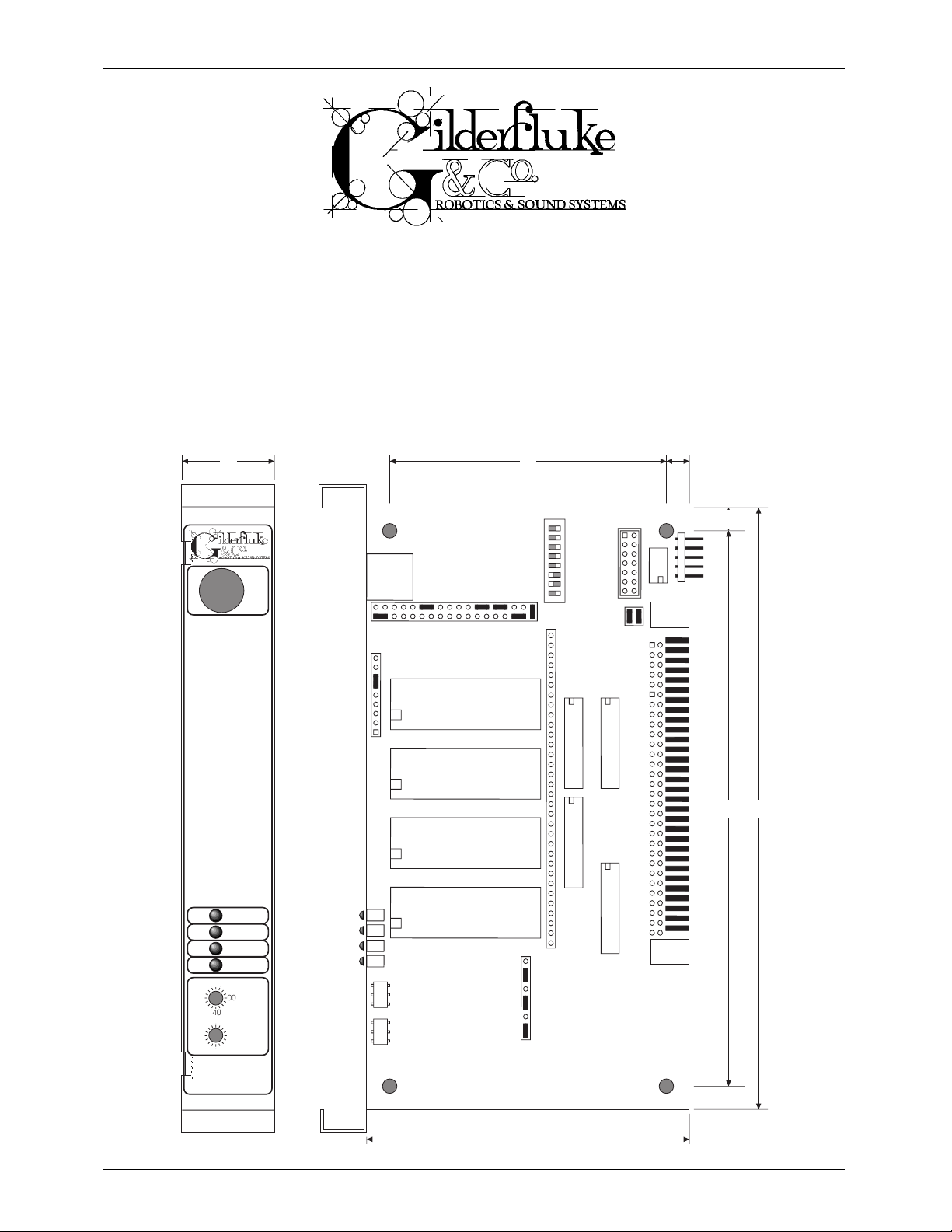
The Micro MACs Brick System is a modular Animation Control System which consists of
any number of Micro MACs Bricks. Since the number of Micro MACs Bricks is unlimited,
Animation Control Systems of any size can be assembled.
1"
3"
"
C0
A0
E0
20
60
40
0C
0A
0E
02
06
04
Dumb
Brick
DMX-
512
Board Error
DMX-512
Running
Heartbeat
0080
Address
0008
DMX-
512
in/out
JP2
JP4
0
U13
channel
1
U14
channel
2
U15
channel
3
U16
channel
JP1
DipSwitch
1
JP3
U18 (ch 1) U19 (ch 2)
0.25"
JP6
U24
JP5
U17 (ch 0)
6.5"6"
U20 (ch 3)
3.5"
Page 2

GILDERFLUKE & CO. ¥ 205 SOUTH FLOWER ST. ¥ BURBANK, CALIF. 91502-2102 ¥ 818/840-9484 ¥ FAX818/840-9485
This page left blank
Page 3

GILDERFLUKE & CO. ¥ 205 SOUTH FLOWER ST. ¥ BURBANK, CALIF. 91502-2102 ¥ 818/840-9484 ¥ FAX818/840-9485
Micro MACs Brick Animation Control Systems Overview ............................... 1
Inputs and Outputs ........................................................................................................... 2
DMX-512 Input ................................................................................................................. .2
Time Bases ........................................................................................................................ 2
Show Capacity ..................................................................................................................3
Micro MACs Brick Jumper Configuration ................................................... 4
Memory Configuration ..................................................................................................... 4
6264LP Ram ................................................................................................................ 4
62256LP Ram .............................................................................................................. 5
27C64 Eprom .............................................................................................................. 5
27C128 Eprom ............................................................................................................ 6
27C256 Eprom ............................................................................................................ 6
27C512 Eprom ............................................................................................................ 7
27C010, 27C020, 27C040 OR 27C080 Eprom ........................................................... 7
Clock Rate Configuration ................................................................................................. 8
15 Frames per Seconds ............................................................................................... 8
16 Frames per Seconds ............................................................................................... 8
30 Frames per Seconds ............................................................................................... 9
32 Frames per Seconds ............................................................................................... 9
External Clock ............................................................................................................ 10
J8 Power ......................................................................................................................... 11
Internal Power ............................................................................................................ 11
External Power ............................................................................................................ 11
Stop or End of Memory Flag ............................................................................................ 12
1024 (1K) Frames ....................................................................................................... 12
2048 (2K) Frames ....................................................................................................... 13
4096 (4K) Frames ....................................................................................................... 13
8192 (8K) Frames ....................................................................................................... 14
16,384 (16K) Frames .................................................................................................. 14
32,768 (32K) Frames .................................................................................................. 15
65,536 (64K) Frames .................................................................................................. 15
131,072 (128K) Frames .............................................................................................. 16
262,144 (256K) Frames .............................................................................................. 16
524,288 (512K) Frames .............................................................................................. 17
1,048,576 (1024K) Frames ......................................................................................... 17
Using Address or Data Bits ........................................................................................... 18
Double Show Configurations .......................................................................................... 20
Double Show using 62256LP Ram .............................................................................. 20
Double Show using 27C128 Eprom ............................................................................ 21
Double Show using 27C256 Eprom ............................................................................ 21
Double Show using 27C512 Eprom ............................................................................ 22
Double Show using 27C020 Eprom ............................................................................ 22
Dipswitch Configuration ....................................................................... 23
Stop on Green Opening .................................................................................................. 23
Stop at End ...................................................................................................................... 23
Reset at End .................................................................................................................... 23
Reset when Stopped ....................................................................................................... 23
No White J8 Input ........................................................................................................... 23
Run Continuously ........................................................................................................... 23
Disable Outputs when Stopped ....................................................................................... 23
DMX Forever! .................................................................................................................. 23
Connections ........................................................................................ 24
J-8 Input ......................................................................................................................... 24
DMX-512 ......................................................................................................................... 24
iii of v
Page 4

GILDERFLUKE & CO. ¥ 205 SOUTH FLOWER ST. ¥ BURBANK, CALIF. 91502-2102 ¥ 818/840-9484 ¥ FAX818/840-9485
Output Capacity ........................................................................................................ 27
Edge Connector .............................................................................................................. 28
Programming ...................................................................................... 29
Micro Console ..................................................................................... 33
Micro Console Configuration ......................................................................................... 35
Micro Console mode ................................................................................................. 36
Numbering System ..................................................................................................... 37
VT-52 mode ............................................................................................................... 37
DMX Checksums ........................................................................................................ 37
Assignment Range ..................................................................................................... 37
Dumb Bricks ............................................................................................................... 37
Step Forward .............................................................................................................. 37
Step Backward ........................................................................................................... 37
Go To Frame .............................................................................................................. 38
Set Start Frame .......................................................................................................... 38
Set End Frame ........................................................................................................... 38
Save Eprom ............................................................................................................... 38
Verify Eprom .............................................................................................................. 38
Restore Eprom ........................................................................................................... 39
Save Archive .............................................................................................................. 39
Verify Archive ............................................................................................................. 40
Restore Archive .......................................................................................................... 40
Clear Brick ................................................................................................................. 40
Restore Default Config. .............................................................................................. 41
Save Current Config. ................................................................................................. 41
Test Brick .................................................................................................................... 41
Test Playback-Only Brick .............................................................................................. 41
Micro Console Buttons ................................................................................................... 43
Hex/Decimal/Percent .................................................................................................. 43
Alternate/Reverse ....................................................................................................... 43
Analog/External/Digitals .............................................................................................. 43
Assign ........................................................................................................................ 44
Unassign .................................................................................................................... 45
Togglodyte Animation Test Tool .............................................................. 47
Assign ........................................................................................................................ 48
Alt./Rev. ..................................................................................................................... 48
Analog/Digital ............................................................................................................ 49
Setup ......................................................................................................................... 49
Special Encoder Prescaler .......................................................................................... 50
Digital Name ........................................................................................................... 50
Digital Number ......................................................................................................... 50
Analog Number ........................................................................................................ 50
Timer A .................................................................................................................... 50
Timer B .................................................................................................................... 50
Timer C ................................................................................................................... 50
Timer D ................................................................................................................... 50
Backlighting Stay On .................................................................................................51
Battery Stay On ......................................................................................................... 51
Default to Digital/Analog Input ..................................................................................... 51
Default Digital Channel .............................................................................................. 51
Digital Default Momentary/Alternate Action ...................................................................... 51
Default Analog Channel ............................................................................................. 51
Analog Default Normal/Reversed Direction ...................................................................... 51
Default Analog Resolution ........................................................................................... 51
DMX-512 Checksum .................................................................................................. 51
iv of v
Page 5

GILDERFLUKE & CO. ¥ 205 SOUTH FLOWER ST. ¥ BURBANK, CALIF. 91502-2102 ¥ 818/840-9484 ¥ FAX818/840-9485
Write to EEprom/Read from EEprom ............................................................................... 51
Light .......................................................................................................................... 51
Sequencer Record .................................................................................................... 51
Start/Stop Sequencer ................................................................................................. 52
HEXadecimal to Decimal to Percentage .................................................. 53
v of v
Page 6

GILDERFLUKE & CO. ¥ 205 SOUTH FLOWER ST. ¥ BURBANK, CALIF. 91502-2102 ¥ 818/840-9484 ¥ FAX818/840-9485
This page was left blank
vi of vi
Page 7

GILDERFLUKE & CO. ¥ 205 SOUTH FLOWER ST. ¥ BURBANK, CALIF. 91502-2102 ¥ 818/840-9484 ¥ FAX818/840-9485
- Micro MACs Brick Animation Control Systems Overview -
The Micro MACs Brick Animation Control Systems are the simplest Animation Control
Systems offered by Gilderfluke & Company. They are used where ever you need an
Animation Control System that will run continuously or when started by an external trigger.
Typical applications are in rides and attractions where the vehicle entering the scene triggers the animation. At the end of the animation sequence, the Animation Control System
will stop and wait for the next vehicle to enter the scene.
Micro MACs Bricks are available as record/playback or playback-only Animation
Control Systems. All record/playback Bricks and many playback-only Bricks come in a
case along with a power supply. These are complete Animation Control Systems which require only power to run.
Micro MACs Bricks are also available as card cage mounted playback-only cards.
These can be plugged into one of the many card cages available from Gilderfluke &
Company. They can also be mounted to a panel on screw standoffs and connected
using a sixty position edge connector if you donÕt want to use a card cage.
The Micro MACs Bricks can all be located at one or more central locations, or they can
be built right into whatever it is they are controlling. This latter method allows you to prewire
an entire attraction. The only field wiring needed is a wire to connect the figures to their trigger sources (if any). This also allows you to bring along a figureÕs Animation Control System
with the figure when it is removed for maintenance. The figure can then be run on your
service bench for testing and adjustment.
Standard Micro MACs ÔBricksÕ are commonly referred to as ÔDumb BricksÕ to differentiate
them from the ÔSmartÕ Bricks in our Smart Brick Animation Control Systems. If you need to
lock to a LaserDisk or Smpte Time Code, or if you need to randomly access many shows,
we recommend you use our Smart Brick Animation Control Systems.
Record/Playback Micro MACs Bricks store the animation data in static Ram memory
chips. These are protected from power outages and data loss by a nickel-cadmium battery. This battery is always on a trickle charge when the Micro MACs Brick is plugged in,
and should hold the data safe for years even when no power is applied. A keyswitch on
the front of each record/playback Micro MACs Brick keeps down the possibility of accidental or unauthorized tampering with recorded show data.
Playback-only Micro MACs Bricks store their data in Eprom type memory chips. This is
about the safest way known to store any type of data. One Eprom is used to store each
individual eight bit wide channel. This means that when you have to perform a minor
change in one output, you donÕt have to replace all the Eproms in the system.
Playback-only Micro MACs Brick Animation Control Systems are programmed using a
record/playback Animation Control system that is used only until the show programming
is completed. In the past, one or more Record/Playback Micro MACs Bricks has often
been used for programming shows. Once programmed, the data is downloaded to a
computer and burnt into the Eproms using a Micro Console. Most shows now use a
PC¥MACs Animation Control System for programming. Many simple shows can even be
programmed just by ÔdrawingÕ the animation sequence on the screen of any PC. No special hardware is required.
1 of 53
Page 8

GILDERFLUKE & CO. ¥ 205 SOUTH FLOWER ST. ¥ BURBANK, CALIF. 91502-2102 ¥ 818/840-9484 ¥ FAX818/840-9485
- Inputs and Outputs -
Each Micro MACs Brick can control up to four 8 bit channels. These can be used as
thirty-two on/off ÔdigitalÕ controls, as four eight bit wide analog channels, or as any combination of the two. If one Micro MACs Brick doesnÕt have enough outputs, you simply add
more, stacking them until you have enough outputs to do your job. Analog resolutions
greater than eight bits can easily be achieved by combining the outputs from more than
a single channel.
Each Micro MACs Brick features four optically isolated inputs and one optically isolated
status output. The four inputs are used as follows. The colors correspond to those found in
six conductor ÔmodularÕ telephone wire:
A) Green ÔStartÕ Input
B) Red ÔStopÕ Input
C) White ÔResetÕ Input
D) Blue ÔExternal ClockÕ or ÔDouble ShowÕ Input
The Yellow ÔRunning StatusÕ output is active whenever the Brick has been Started. These
Inputs and Outputs can be configured to use the same power supply as the rest of the
Brick, or an external power supply can be used.
- DMX-512 Input -
The DMX-512 standard was developed by the United States Institute for Theatrical
Technology (USITT) for a high speed (250 KBaud asynchronous) serial link. Although it was
originally designed for controlling light dimmers, it is now supported by hundreds of suppliers throughout the world for controlling all kinds of theatrical equipment.
Playback-only Micro MACs Bricks are available which will receive DMX-512 data directly. This is the high speed serial data that PC¥MACs outputs. This allows data from a
PC¥MACs system to be sent directly to a Micro MACs Brick System. Typically Bricks with the
DMX-512 capability are used only during programming. They are replaced by other
bricks once programming is completed.
Even though the DMX-512 standard calls for 512 channels of data, the DMX transmission from PC¥MACs is limited to 256 eight bit wide channels. You can address DMX capable Micro MACs Brick to respond to any address between 0 and 255. Addresses
above the 256th are used in PC¥MACs for transmitting a checksum. All Gilderfluke &
Company DMX-512 compatible equipment can use this to verify that the data received
from PC¥MACs has no transmission errors in it. If you address a light dimmer or other DMX512 device to addresses 256 or 257, you will see this verification data displayed as a flickering pattern.
- Time Bases -
Micro MACs Bricks can run from their own onboard crystal controlled time base at 15,
16, 30, or 32 frames per second1. If different frame rates are required, an external clock
can be fed to Micro MACs Bricks. The Micro MACs Bricks will accept external clock rates
from zero to approximately 1000 frames per second.
1
Other frame rates are available as special orders.
2 of 53
Page 9

GILDERFLUKE & CO. ¥ 205 SOUTH FLOWER ST. ¥ BURBANK, CALIF. 91502-2102 ¥ 818/840-9484 ¥ FAX818/840-9485
- Show Capacity -
The Show length that can be stored on a Micro MACs Brick is only limited by the size of
the memory installed and the number of updates per second you are using. With the
largest Eproms you have a potential capacity of almost ten hours at 30 FPS.
Record/Playback Micro MACs Bricks are available with either 16K (16,384 frames) or 64K
(65,536) capacities.
Memory
# frames 15 FPS 16 FPS 30 FPS 32 FPS
27C32 4096 4.6 min. 4.3 min. 2.3 min. 2.1 min.
27C64 8192 9.1 min. 8.5 min. 4.6 min. 4.3 min.
27C128 16,384 18.2 min. 17.1 min. 9.1 min. 8.5 min.
27C256 32,768 36.4 min. 34.1 min. 18.2 min. 17.1 min.
27C512 65,536 72.8 min. 68.3 min. 36.4 min. 34.1 min.
27C010 131,072 145.6 min. 136.5 min. 72.8 min. 68.3 min.
27C020 262,144 291.3 min. 273.1 min. 145.6 min. 136.5 min.
27C040 524,288 582.5 min. 546.1 min. 291.3 min. 273.1 min.
27C080 1,048,576 1165.1 min. 1092.3 min. 582.5 min. 546.1 min.
3 of 53
Page 10
GILDERFLUKE & CO. ¥ 205 SOUTH FLOWER ST. ¥ BURBANK, CALIF. 91502-2102 ¥ 818/840-9484 ¥ FAX818/840-9485
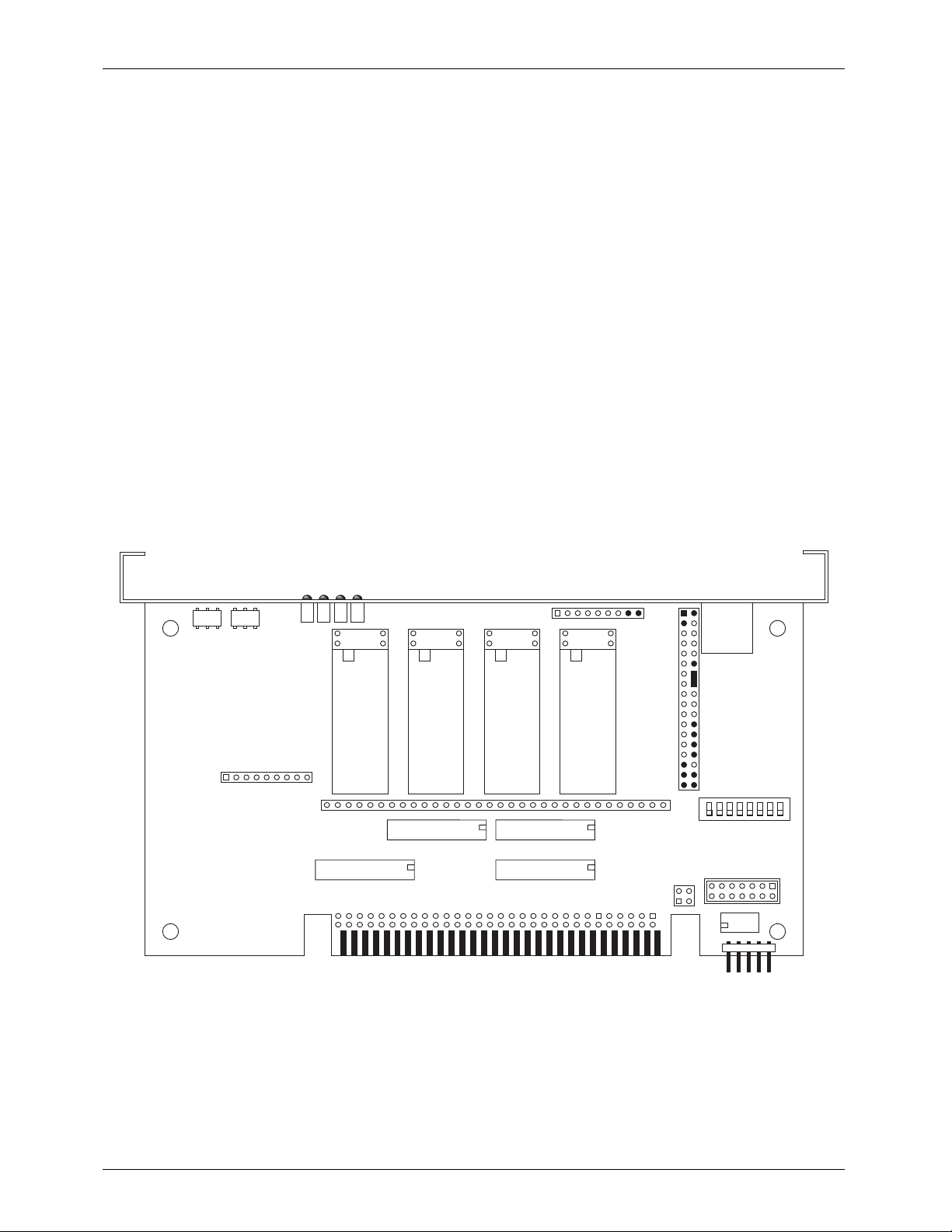
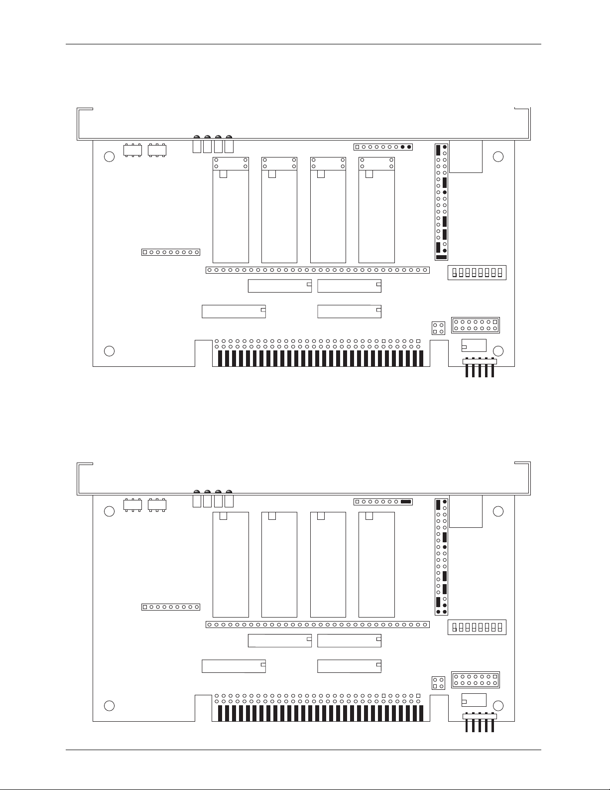
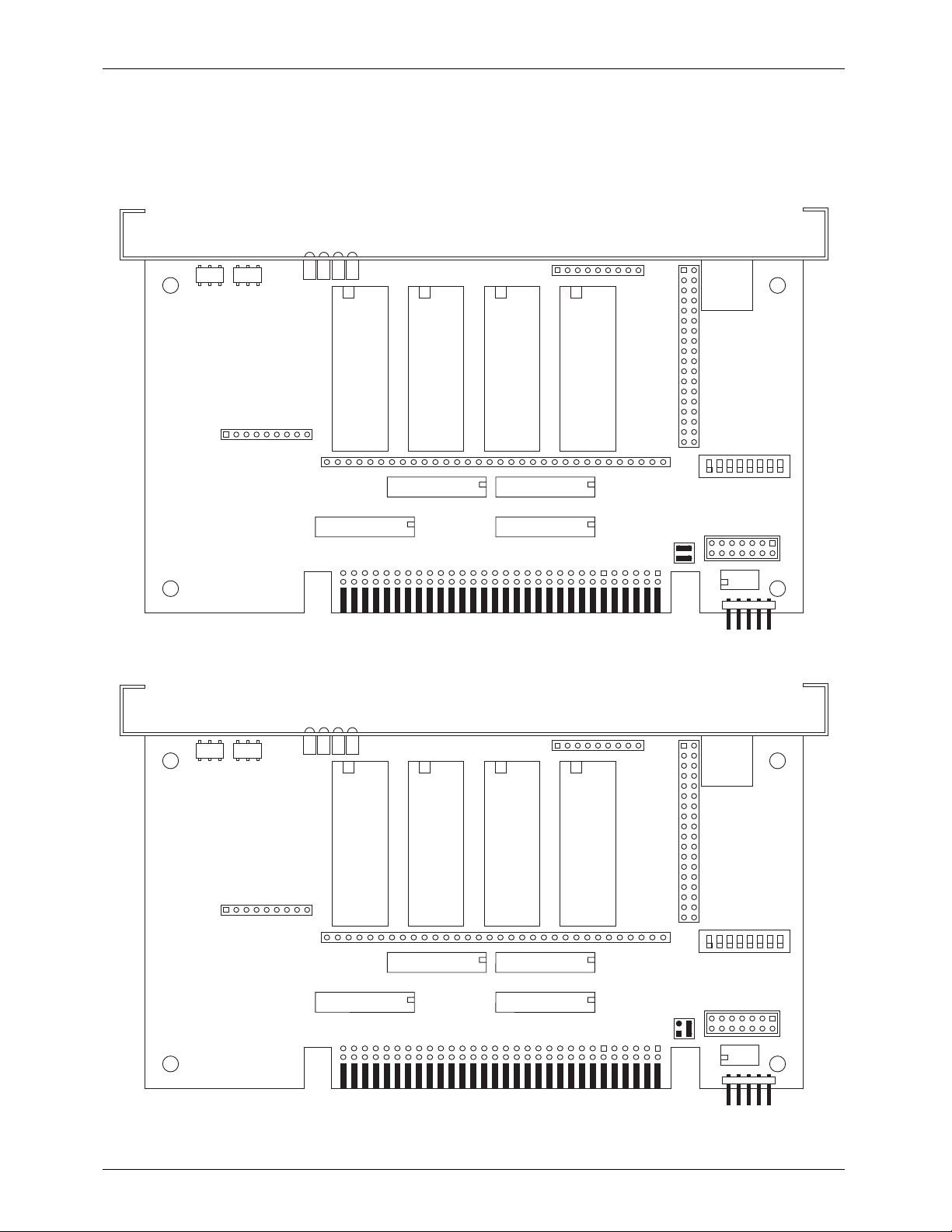
- Micro MACs Brick Jumper Configuration -
The majority of the configuration for the Micro MACs Bricks is done on an eight position Dipswitch.
The exceptions to this are those jumpers which set:
A) size and type of memory used
B) internal/external clock source and frame rate
C) Internal/External power for the J-8 Optoisolated inputs
D) Stop and/or end of memory jumpers needed in some configurations
E) Double show configuration (if used)
In all the following drawings, the jumper pins are shown as circles contained within an outline of the
header assembly. Pins that are used for a given configuration are shown as filled-in, while those which
remain hollow are not being used. The jumper plugs (used for connecting adjacent pins) or wires (used
for connecting pins that are not adjacent) which connect the pins are shown as black lines. Any pin
which is shown filled in with black, but which does not have any wire or jumper plug shown on it, must
have all wires and/or jumper plugs removed from it in the actual Micro MACs Brick you are configuring.
- Memory Configuration -
The type of memory to be used is set on JP2 and JP4. These jumpers must be set before you
install your memory chips and power up the Micro MACs Brick. You shouldnÕt change any of the
jumpers on the other headers when this setting is changed.
- 6264LP Ram -
To configure a Record/Playback Micro MACs Brick for use with 6264LP static Ram Chips for a
capacity of 16,384 (16K) frames. The RAM chips must be ÔSouthÕ justified, leaving four unused
holes at the top of each socket.
DMX-512 Address
JP1
DMX Error
DMX data
Brick Run
DMX heart
JP4
6264LP 6264LP 6264LP 6264LP
channel
3
U16
channel
2
U15
U20 (ch 3)
channel
1
U14
channel
0
U13
U18 (ch 1) U19 (ch 2)
U17 (ch 0)
JP3
JP5
JP2
DMX-
512
in/out
1
DipSwitch
JP6
U24
4 of 53
Page 11
GILDERFLUKE & CO. ¥ 205 SOUTH FLOWER ST. ¥ BURBANK, CALIF. 91502-2102 ¥ 818/840-9484 ¥ FAX818/840-9485
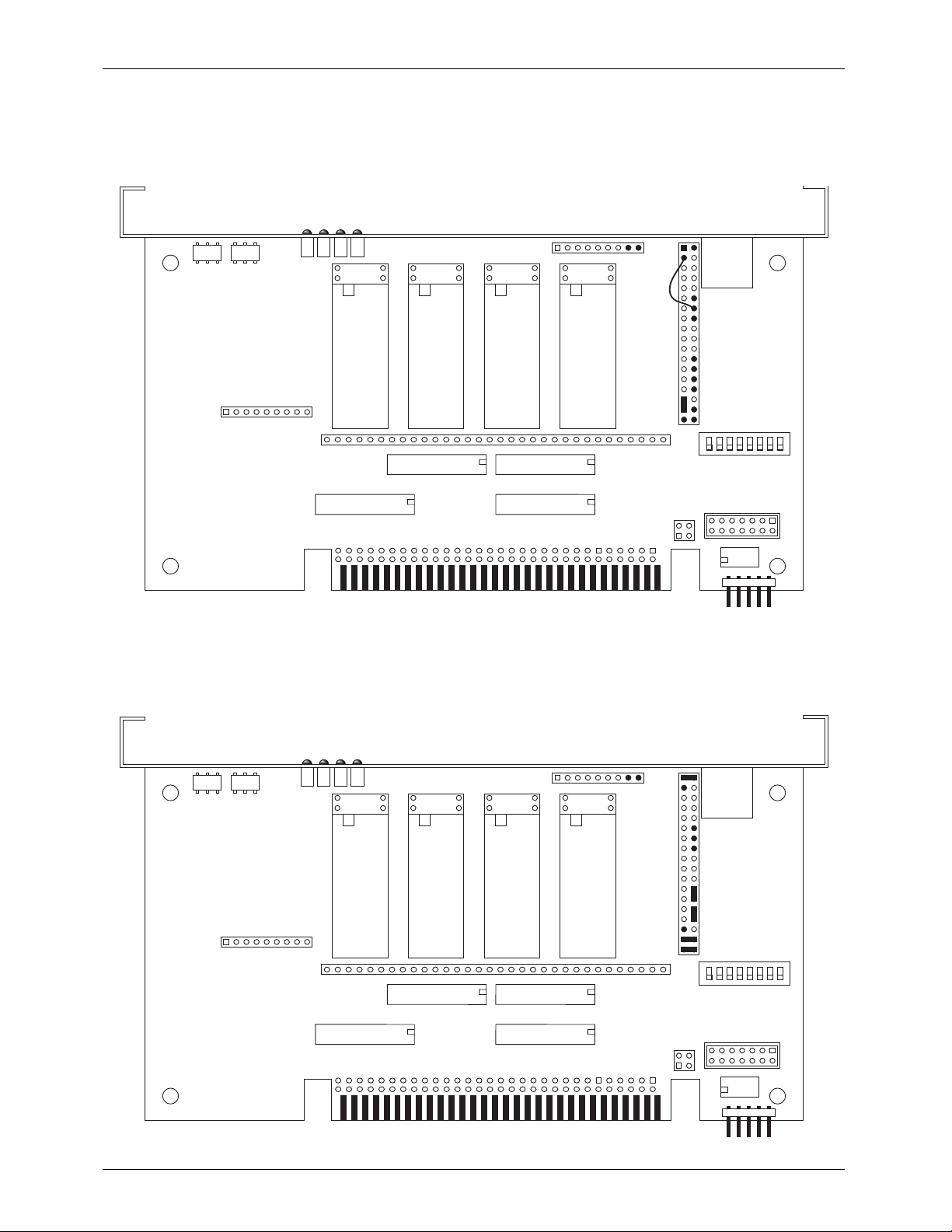
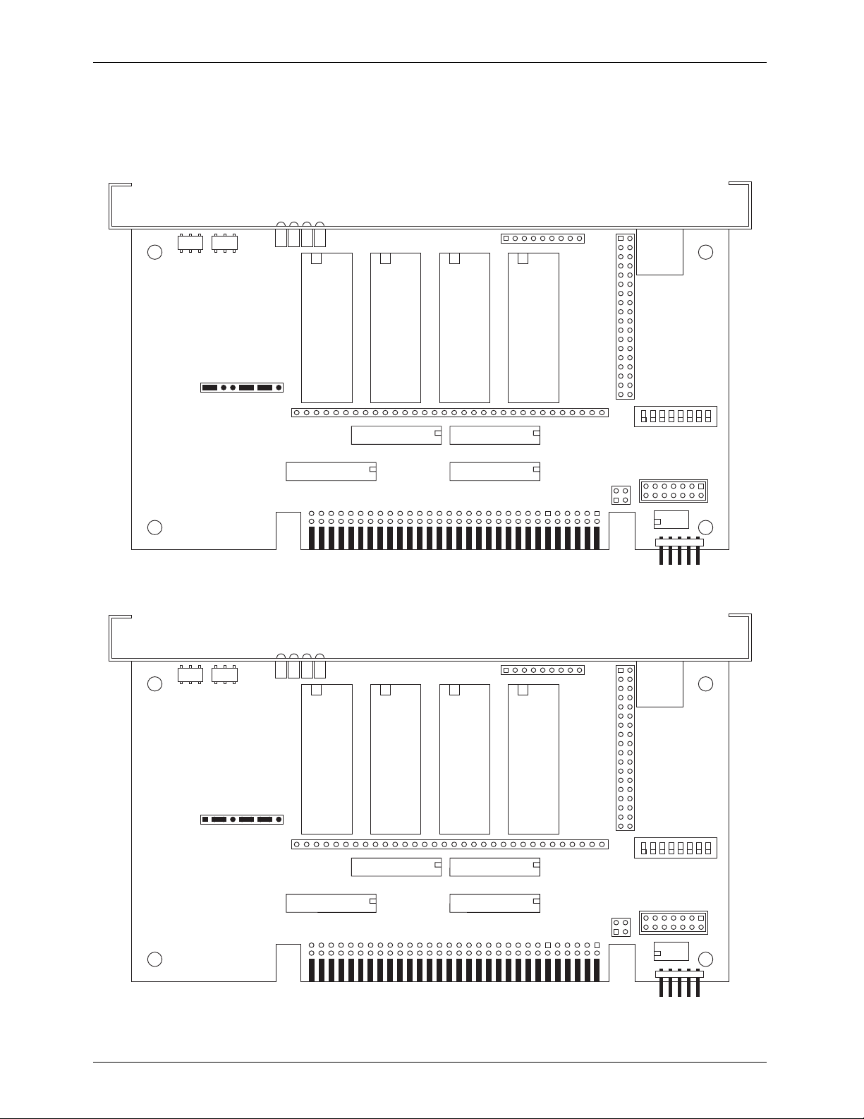
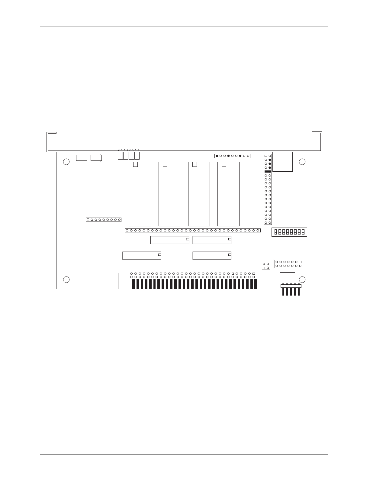
- 62256LP Ram -
To configure a Record/Playback Micro MACs Brick for use with 62256LP static Ram Chips for a
capacity of 65,536 (64K). This is the only memory configuration which requires a wire wrapped
jumper between two pins. The RAM chips must be ÔSouthÕ justified, leaving four unused holes at
the top of each socket.
DMX Error
DMX data
Brick Run
DMX-512 Address
DMX heart
JP4
62256LP 62256LP 62256LP 62256LP
JP2
DMX-
512
in/out
channel
0
U13
U18 (ch 1) U19 (ch 2)
U17 (ch 0)
JP3
JP5
1
DipSwitch
JP6
U24
JP1
channel
3
U16
channel
2
U15
U20 (ch 3)
channel
1
U14
- 27C64 Eprom -
To configure a Playback-only Micro MACs Brick for use with 27C64 Eprom for a capacity of
8192 (8K) frames. The Eprom chips must be ÔSouthÕ justified, leaving four unused holes at the top
of each socket.
DMX Error
DMX data
Brick Run
DMX-512 Address
DMX heart
JP4
JP2
DMX-
512
in/out
JP1
27C64 27C64 27C64 27C64
channel
3
U16
channel
2
U15
U20 (ch 3)
channel
1
U14
channel
0
U13
U18 (ch 1) U19 (ch 2)
U17 (ch 0)
5 of 53
JP3
JP5
1
DipSwitch
JP6
U24
Page 12
GILDERFLUKE & CO. ¥ 205 SOUTH FLOWER ST. ¥ BURBANK, CALIF. 91502-2102 ¥ 818/840-9484 ¥ FAX818/840-9485
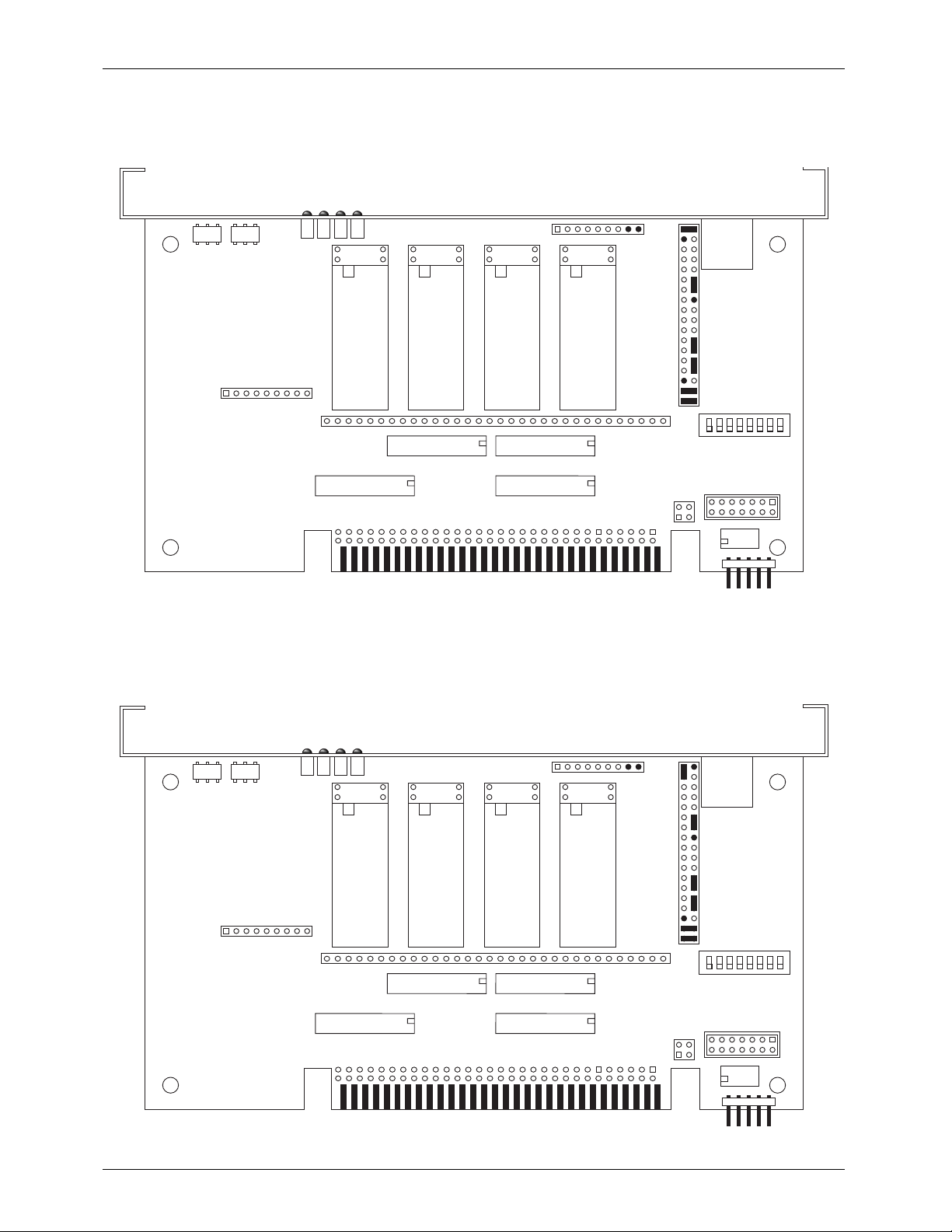
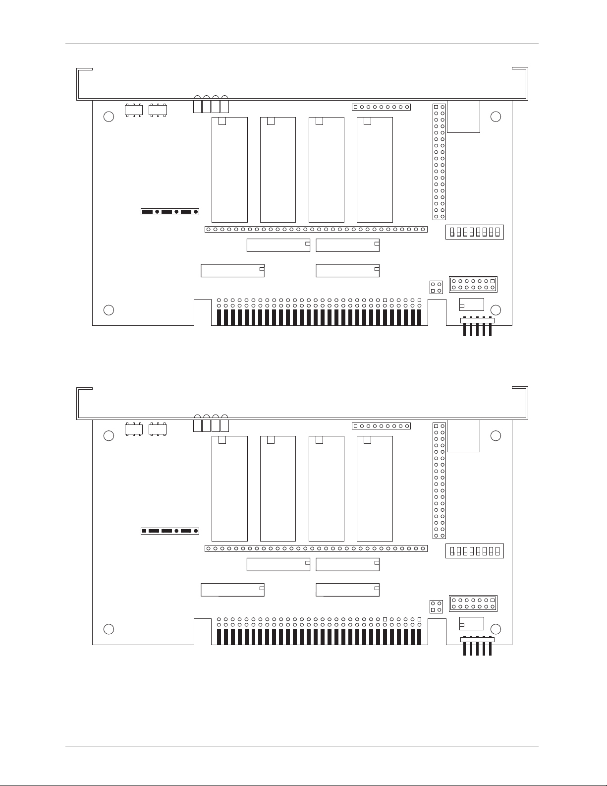
- 27C128 Eprom -
To configure a Playback-only Micro MACs Brick for use with 27C128 Eprom for a capacity of
16,384 (16K) frames. The Eprom chips must be ÔSouthÕ justified, leaving four unused holes at the
top of each socket.
DMX Error
DMX data
Brick Run
DMX-512 Address
DMX heart
JP4
27C128 27C128 27C128 27C128
JP2
DMX-
512
in/out
channel
0
U13
U18 (ch 1) U19 (ch 2)
U17 (ch 0)
JP3
JP5
1
DipSwitch
JP6
U24
JP1
channel
3
U16
channel
2
U15
U20 (ch 3)
channel
1
U14
- 27C256 Eprom -
To configure a Playback-only Micro MACs Brick for use with 27C256 Eprom for a capacity of
32,768 (32K) frames. The Eprom chips must be ÔSouthÕ justified, leaving four unused holes at the
top of each socket.
DMX Error
DMX data
Brick Run
DMX-512 Address
DMX heart
JP4
JP2
DMX-
512
in/out
JP1
27C256 27C256 27C256 27C256
channel
3
U16
channel
2
U15
U20 (ch 3)
channel
1
U14
channel
0
U13
U18 (ch 1) U19 (ch 2)
U17 (ch 0)
6 of 53
JP3
JP5
1
DipSwitch
JP6
U24
Page 13
GILDERFLUKE & CO. ¥ 205 SOUTH FLOWER ST. ¥ BURBANK, CALIF. 91502-2102 ¥ 818/840-9484 ¥ FAX818/840-9485
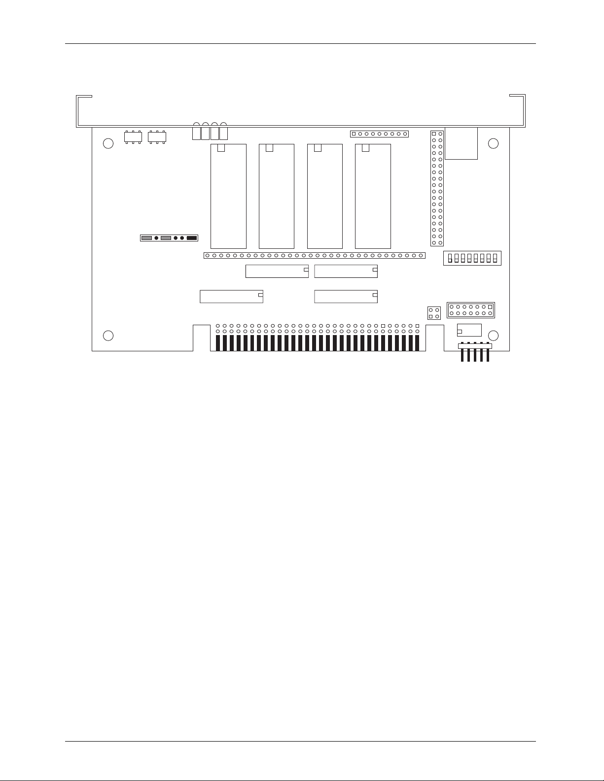
- 27C512 Eprom -
To configure a Playback-only Micro MACs Brick for use with 27C512 Eprom for a capacity of
65,536 (64K) frames The Eprom chips must be ÔSouthÕ justified, leaving four unused holes at the
top of each socket.
DMX Error
DMX data
Brick Run
DMX-512 Address
DMX heart
JP4
27C512 27C512 27C512 27C512
JP2
DMX-
512
in/out
channel
1
U14
JP1
channel
3
U16
channel
2
U15
U20 (ch 3)
- 27C010, 27C020, 27C040 OR 27C080 Eprom -
To configure a Playback-only Micro MACs Brick for use with:
27C010 Eprom for a capacity of 131,072 (128K) frames
27C020 Eprom for a capacity of 262,144 (256K) frames
27C040 Eprom for a capacity of 524,288 (512K) frames
27C080 Eprom for a capacity of 1,048,576 (1024K) frames
DMX Error
DMX data
Brick Run
DMX-512 Address
DMX heart
27C010
27C020
27C040
27C080
27C010
27C020
27C040
27C080
27C010
27C020
27C040
27C080
JP4
27C010
27C020
27C040
27C080
channel
0
U13
U18 (ch 1) U19 (ch 2)
U17 (ch 0)
JP3
JP5
JP2
1
DipSwitch
JP6
U24
DMX-
512
in/out
JP1
channel
3
U16
channel
2
U15
U20 (ch 3)
7 of 53
channel
1
U14
channel
0
U13
U18 (ch 1) U19 (ch 2)
U17 (ch 0)
JP3
JP5
1
DipSwitch
JP6
U24
Page 14
GILDERFLUKE & CO. ¥ 205 SOUTH FLOWER ST. ¥ BURBANK, CALIF. 91502-2102 ¥ 818/840-9484 ¥ FAX818/840-9485
- Clock Rate Configuration -
The clock source and frame rate are set on JP1. If the standard frame rates are not to your liking, other frame rates may be available from the Gilderfluke & Company factory. You shouldnÕt
change any of the jumpers on the other headers when this setting is changed.
- 15 Frames per Seconds -
DMX data
Brick Run
DMX heart
DMX-512 Address
DMX Error
JP4
JP2
DMX-
512
in/out
JP1
DMX-512 Address
channel
3
U16
channel
2
U15
U20 (ch 3)
channel
1
U14
- 16 Frames per Seconds -
DMX data
Brick Run
DMX heart
DMX Error
JP4
channel
0
U13
U18 (ch 1) U19 (ch 2)
U17 (ch 0)
JP3
JP5
JP2
1
DipSwitch
JP6
U24
DMX-
512
in/out
JP1
channel
3
U16
channel
2
U15
U20 (ch 3)
8 of 53
channel
1
U14
channel
0
U13
U18 (ch 1) U19 (ch 2)
U17 (ch 0)
JP3
JP5
1
DipSwitch
JP6
U24
Page 15
GILDERFLUKE & CO. ¥ 205 SOUTH FLOWER ST. ¥ BURBANK, CALIF. 91502-2102 ¥ 818/840-9484 ¥ FAX818/840-9485
- 30 Frames per Seconds -
DMX data
Brick Run
DMX heart
DMX-512 Address
DMX Error
JP4
JP2
DMX-
512
in/out
JP1
DMX-512 Address
channel
3
U16
channel
2
U15
U20 (ch 3)
channel
1
U14
- 32 Frames per Seconds -
DMX data
Brick Run
DMX heart
DMX Error
JP4
channel
0
U13
U18 (ch 1) U19 (ch 2)
U17 (ch 0)
JP3
JP5
JP2
1
DipSwitch
JP6
U24
DMX-
512
in/out
JP1
channel
3
U16
channel
2
U15
U20 (ch 3)
9 of 53
channel
1
U14
channel
0
U13
U18 (ch 1) U19 (ch 2)
U17 (ch 0)
JP3
JP5
1
DipSwitch
JP6
U24
Page 16
GILDERFLUKE & CO. ¥ 205 SOUTH FLOWER ST. ¥ BURBANK, CALIF. 91502-2102 ¥ 818/840-9484 ¥ FAX818/840-9485
- External Clock -
The internal clock is incompatible with the double show configuration. They both use the Blue
Input.
DMX data
Brick Run
DMX heart
DMX-512 Address
DMX Error
JP4
JP2
DMX-
512
in/out
JP1
channel
3
U16
channel
2
U15
U20 (ch 3)
channel
1
U14
channel
0
U13
U18 (ch 1) U19 (ch 2)
U17 (ch 0)
JP3
JP5
1
DipSwitch
JP6
U24
10 of 53
Page 17
GILDERFLUKE & CO. ¥ 205 SOUTH FLOWER ST. ¥ BURBANK, CALIF. 91502-2102 ¥ 818/840-9484 ¥ FAX818/840-9485
- J8 Power -
The source of power used for the J8 input/output is set using two jumpers on JP5. External
power should be selected whenever possible. You shouldnÕt change any of the jumpers on the
other headers when this setting is changed.
- Internal Power -
DMX data
Brick Run
DMX heart
DMX-512 Address
DMX Error
JP4
JP2
DMX-
512
in/out
JP1
DMX-512 Address
channel
Brick Run
DMX heart
channel
3
U16
2
U15
U20 (ch 3)
- External Power -
DMX data
DMX Error
channel
1
U14
JP4
channel
0
U13
U18 (ch 1) U19 (ch 2)
U17 (ch 0)
JP3
JP5
JP2
1
DipSwitch
JP6
U24
DMX-
512
in/out
JP1
channel
3
U16
channel
2
U15
U20 (ch 3)
channel
11 of 53
1
U14
channel
0
U13
U18 (ch 1) U19 (ch 2)
U17 (ch 0)
JP3
JP5
1
DipSwitch
JP6
U24
Page 18
GILDERFLUKE & CO. ¥ 205 SOUTH FLOWER ST. ¥ BURBANK, CALIF. 91502-2102 ¥ 818/840-9484 ¥ FAX818/840-9485
- Stop or End of Memory Flag -
The Micro MACs Brick has five wire -ORed inputs which can be jumpered to set the ÔStop or
End of MemoryÕ flag when all of these pins go to a high state (floating is also considered a ÔhighÕ
state). The Dipswitches can be configured to stop and/or reset the Brick when this flag is set. The
typical use for this input is to:
A) Set flag to stop or reset at the end of the installed memory
B) Set flag to stop or reset at a certain frame is reached in the show
C) Set flag to stop or reset when a certain combination of up to five data bits are set
To set this flag at the following frame numbers, install the jumpers as shown:
- Stop/Reset at 1024 (1K) Frames -
DMX data
Brick Run
DMX heart
DMX-512 Address
DMX Error
JP4
JP2
DMX-
512
in/out
JP1
channel
3
U16
channel
2
U15
U20 (ch 3)
channel
1
U14
channel
0
U13
U18 (ch 1) U19 (ch 2)
U17 (ch 0)
JP3
JP5
1
DipSwitch
JP6
U24
12 of 53
Page 19

GILDERFLUKE & CO. ¥ 205 SOUTH FLOWER ST. ¥ BURBANK, CALIF. 91502-2102 ¥ 818/840-9484 ¥ FAX818/840-9485
- Stop/Reset at 2048 (2K) Frames -
DMX data
Brick Run
DMX heart
DMX-512 Address
DMX Error
JP4
JP2
DMX-
512
in/out
JP1
DMX-512 Address
channel
3
U16
channel
2
U15
U20 (ch 3)
channel
1
U14
channel
0
U13
U18 (ch 1) U19 (ch 2)
U17 (ch 0)
- Stop/Reset at 4096 (4K) Frames -
DMX data
Brick Run
DMX heart
DMX Error
JP4
JP3
JP5
JP2
1
DipSwitch
JP6
U24
DMX-
512
in/out
JP1
channel
3
U16
channel
2
U15
U20 (ch 3)
channel
13 of 53
1
U14
channel
0
U13
U18 (ch 1) U19 (ch 2)
U17 (ch 0)
JP3
JP5
1
DipSwitch
JP6
U24
Page 20

GILDERFLUKE & CO. ¥ 205 SOUTH FLOWER ST. ¥ BURBANK, CALIF. 91502-2102 ¥ 818/840-9484 ¥ FAX818/840-9485
- Stop/Reset at 8192 (8K) Frames -
DMX data
Brick Run
DMX heart
DMX-512 Address
DMX Error
JP4
JP2
DMX-
512
in/out
JP1
DMX-512 Address
channel
3
U16
channel
2
U15
U20 (ch 3)
channel
1
U14
channel
0
U13
U18 (ch 1) U19 (ch 2)
U17 (ch 0)
JP3
- Stop/Reset at 16,384 (16K) Frames -
DMX data
Brick Run
DMX heart
DMX Error
JP4
JP5
JP2
1
DipSwitch
JP6
U24
DMX-
512
in/out
JP1
channel
3
U16
channel
2
U15
U20 (ch 3)
channel
14 of 53
1
U14
channel
0
U13
U18 (ch 1) U19 (ch 2)
U17 (ch 0)
JP3
JP5
1
DipSwitch
JP6
U24
Page 21

GILDERFLUKE & CO. ¥ 205 SOUTH FLOWER ST. ¥ BURBANK, CALIF. 91502-2102 ¥ 818/840-9484 ¥ FAX818/840-9485
- Stop/Reset at 32,768 (32K) Frames -
DMX data
Brick Run
DMX heart
DMX-512 Address
DMX Error
JP4
JP2
DMX-
512
in/out
JP1
DMX-512 Address
channel
3
U16
channel
2
U15
U20 (ch 3)
channel
1
U14
channel
0
U13
U18 (ch 1) U19 (ch 2)
U17 (ch 0)
JP3
- Stop/Reset at 65,536 (64K) Frames -
DMX data
Brick Run
DMX heart
DMX Error
JP4
JP5
JP2
1
DipSwitch
JP6
U24
DMX-
512
in/out
JP1
channel
3
U16
channel
2
U15
U20 (ch 3)
channel
15 of 53
1
U14
channel
0
U13
U18 (ch 1) U19 (ch 2)
U17 (ch 0)
JP3
JP5
1
DipSwitch
JP6
U24
Page 22

GILDERFLUKE & CO. ¥ 205 SOUTH FLOWER ST. ¥ BURBANK, CALIF. 91502-2102 ¥ 818/840-9484 ¥ FAX818/840-9485
- Stop/Reset at 131,072 (128K) Frames -
DMX data
Brick Run
DMX heart
DMX-512 Address
DMX Error
JP4
JP2
DMX-
512
in/out
JP1
DMX-512 Address
channel
3
U16
channel
2
U15
U20 (ch 3)
channel
1
U14
channel
0
U13
U18 (ch 1) U19 (ch 2)
U17 (ch 0)
JP3
JP5
- Stop/Reset at 262,144 (256K) Frames -
DMX data
Brick Run
DMX heart
DMX Error
JP4
JP2
1
DipSwitch
JP6
U24
DMX-
512
in/out
JP1
channel
3
U16
channel
2
U15
U20 (ch 3)
channel
16 of 53
1
U14
channel
0
U13
U18 (ch 1) U19 (ch 2)
U17 (ch 0)
JP3
JP5
1
DipSwitch
JP6
U24
Page 23

GILDERFLUKE & CO. ¥ 205 SOUTH FLOWER ST. ¥ BURBANK, CALIF. 91502-2102 ¥ 818/840-9484 ¥ FAX818/840-9485
- Stop/Reset at 524,288 (512K) Frames -
DMX data
Brick Run
DMX heart
DMX-512 Address
DMX Error
JP4
JP2
DMX-
512
in/out
JP1
- Stop/Reset at 1,048,576 (1024K) Frames -
DMX-512 Address
channel
Brick Run
DMX heart
3
U16
DMX data
DMX Error
channel
2
U15
U20 (ch 3)
channel
1
U14
JP4
channel
0
U13
U18 (ch 1) U19 (ch 2)
U17 (ch 0)
JP3
JP5
JP2
1
DipSwitch
JP6
U24
DMX-
512
in/out
JP1
channel
3
U16
channel
2
U15
U20 (ch 3)
channel
17 of 53
1
U14
channel
0
U13
U18 (ch 1) U19 (ch 2)
U17 (ch 0)
JP3
JP5
1
DipSwitch
JP6
U24
Page 24

GILDERFLUKE & CO. ¥ 205 SOUTH FLOWER ST. ¥ BURBANK, CALIF. 91502-2102 ¥ 818/840-9484 ¥ FAX818/840-9485
- Stop or Reset Using Address or Data Bits -
You can use between one and five bits of any address or data word to set the ÔStop or End of
MemoryÕ flag. To do this you will need to wire-wrap a connection from the appropriate data and/or
address bits to one or more of the five pins that will set the Stop or End of Memory flag. These pins
are shown in black in the following illustration. Any of these pins that are left unconnected assume
a ÔhighÕ state.
To stop from one or more data bits:
A) select the data bit(s) you wish to stop from. All thirty-two bits appear on JP3 at the center
of the board. If you use more than one data bit, then the Stop or End of Memory flag
will not be set until all of the attached bits go to a high state simultaneously.
B) Wire wrap a connection between each of the selected data bits and one of the five
pins that will set the Stop or End of Memory flag. Only one data bit can be attached to
each of these pins.
The stops and resets can also be wired externally to the Brick card. You do this by running the
output from the bit that will stop/reset the brick back into the stop or reset inputs to the card. This
will work better for applications that use more than one card.
DMX Error
DMX data
Brick Run
DMX-512 Address
JP1
DMX heart
JP4
channel
3
U16
channel 3 channel 2 channel 1 channel 0
0 1234567 01 234 5670123 4567 01234 567
channel
2
U15
channel
1
U14
262,144
1,048,576
channel
0
U13
U18 (ch 1) U19 (ch 2)
65,536
524,288
131,072
JP2
16,384
4096
2048
1024
32,768
JP3
512
256
128
DMX-
512
in/out
8192
64
32
16
8
4
2
1
1
DipSwitch
U20 (ch 3)
U17 (ch 0)
JP6
JP5
U24
If you need to stop the MICRO MACs from the frame counter at some unique address, you
must first determine the binary equivalent of that frame number. For example, suppose you want
to stop the show at the end of one minute. Convert the running time (one minute) to seconds
(60) and multiply that by the frame rate (in this case we will use 16 frames per second). This yields
a required show length of 960 frames. To convert this 960 into a binary number, select the largest
of the frame counter pins that will fit into 960. In this example it is 512. Subtract this number from
the total number of frames.
960
-512
448
The remainder is 448. Since you were able to subtract the number 512, make a note that you
will be using the 512 frame counter pin. Repeat the process, starting with the remainder 448.
Each time you find which is the largest frame counter pin that you can subtract, make a note that
you are using that frame counter pin. Continue to repeat the process until the remainder is zero.
448
18 of 53
Page 25

GILDERFLUKE & CO. ¥ 205 SOUTH FLOWER ST. ¥ BURBANK, CALIF. 91502-2102 ¥ 818/840-9484 ¥ FAX818/840-9485
-256
192
-128
64
-64
0
Each frame counter pin you subtracted is then wired to one of the stop pins. Configured in
this way, the MICRO MACs will run from the beginning to the 960th frame and then stop. (It will
stop on the 960th frame).
If you used a calculator to convert the frame number into binary address then a Ò1Ó indicates
a connection and a Ò0Ó does not. The right hand most digit stands for the Ò1Ó address counter pin,
the 2nd from the right indicates the Ò2Ó pin, the 3rd indicates the Ò4Ó pin and so on, doubling the
number associated with the pin each digit you move toward the left.
This example happens to use four of the five stop inputs. To get to the exact frame number
might take more than the five available inputs. In this case, use the five most significant pins you
found. If this doesnÕt get you close enough, then you should consider stopping from a show data
bit.
When using this (frame counter) method of stopping or resetting a MICRO MACs, the show
must start each time at the beginning. This can be assured by configuring the start and reset both
on the same (J-8) input.
19 of 53
Page 26

GILDERFLUKE & CO. ¥ 205 SOUTH FLOWER ST. ¥ BURBANK, CALIF. 91502-2102 ¥ 818/840-9484 ¥ FAX818/840-9485
- Double Show Configurations -
Several memory types can be configured to divide the memory into two identical ÔbanksÕ.
When the Micro MACs Brick is switched, the Brick will instantly find itself at the exact same frame
on the other bank.
When using the double show configuration, the Blue Input is used to select between the two
banks. This makes double show configurations incompatible with the external clock.
- Double Show using 62256LP Ram -
To configure a Record/Playback Micro MACs Brick for use with 62256LP static Ram Chips for a
capacity of two 32,768 (32K) banks. The RAM chips must be ÔSouthÕ justified, leaving four unused
holes at the top of each socket.
DMX Error
DMX data
Brick Run
DMX-512 Address
DMX heart
JP4
62256LP 62256LP 62256LP 62256LP
JP2
DMX-
512
in/out
JP1
channel
3
U16
channel
2
U15
U20 (ch 3)
channel
1
U14
channel
0
U13
U18 (ch 1) U19 (ch 2)
U17 (ch 0)
JP3
JP5
1
DipSwitch
JP6
U24
20 of 53
Page 27

GILDERFLUKE & CO. ¥ 205 SOUTH FLOWER ST. ¥ BURBANK, CALIF. 91502-2102 ¥ 818/840-9484 ¥ FAX818/840-9485
- Double Show using 27C128 Eprom -
To configure a Playback-only Micro MACs Brick for use with 27C128 Eprom Chips for a capacity of two 8192 (8K) banks. The Eprom chips must be ÔSouthÕ justified, leaving four unused holes at
the top of each socket.
DMX Error
DMX data
Brick Run
DMX-512 Address
DMX heart
JP4
27C128 27C128 27C128 27C128
JP2
DMX-
512
in/out
channel
0
U13
U18 (ch 1) U19 (ch 2)
U17 (ch 0)
JP3
JP5
1
DipSwitch
JP6
U24
JP1
channel
3
U16
channel
2
U15
U20 (ch 3)
channel
1
U14
- Double Show using 27C256 Eprom -
To configure a Playback-only Micro MACs Brick for use with 27C256 Eprom Chips for a capacity of two 16,384 (16K) banks. The Eprom chips must be ÔSouthÕ justified, leaving four unused holes
at the top of each socket.
DMX Error
DMX data
Brick Run
DMX-512 Address
DMX heart
JP4
JP2
DMX-
512
in/out
JP1
27C256 27C256 27C256 27C256
channel
3
U16
channel
2
U15
U20 (ch 3)
channel
1
U14
channel
0
U13
U18 (ch 1) U19 (ch 2)
U17 (ch 0)
21 of 53
JP3
JP5
1
DipSwitch
JP6
U24
Page 28

GILDERFLUKE & CO. ¥ 205 SOUTH FLOWER ST. ¥ BURBANK, CALIF. 91502-2102 ¥ 818/840-9484 ¥ FAX818/840-9485
- Double Show using 27C512 Eprom -
To configure a Playback-only Micro MACs Brick for use with 27C512 Eprom Chips for a capacity of two 32,768 (32K) banks. The Eprom chips must be ÔSouthÕ justified, leaving four unused holes
at the top of each socket.
DMX Error
DMX data
Brick Run
DMX-512 Address
DMX heart
JP4
27C512 27C512 27C512 27C512
JP2
DMX-
512
in/out
channel
0
U13
U18 (ch 1) U19 (ch 2)
U17 (ch 0)
JP3
JP5
1
DipSwitch
U24
JP1
channel
3
U16
channel
2
U15
U20 (ch 3)
channel
1
U14
- Double Show using 27C020 Eprom -
To configure a Playback-only Micro MACs Brick for use with 27C020 Eprom Chips for a capacity of two 131,072 (128K) banks.
DMX data
Brick Run
DMX heart
DMX-512 Address
DMX Error
JP4
JP2
DMX-
512
in/out
JP6
JP1
27C020 27C020 27C020 27C020
channel
3
U16
channel
2
U15
U20 (ch 3)
channel
1
U14
channel
0
U13
U18 (ch 1) U19 (ch 2)
U17 (ch 0)
22 of 53
JP3
JP5
1
DipSwitch
JP6
U24
Page 29

GILDERFLUKE & CO. ¥ 205 SOUTH FLOWER ST. ¥ BURBANK, CALIF. 91502-2102 ¥ 818/840-9484 ¥ FAX818/840-9485
- Micro MACs Brick Dipswitch Configuration -
Dipswitch #1: Stop on Green Opening: The Green J8 input will always start the Micro MACs Brick.
When this switch is ON, the Micro MACs Brick will stop when on the opening of the Green J8
input. This switch will have no effect if dipswitch #6 (run continuously) is ON. The Dipswitch #2
(Stop at End) and the Red (Stop) J8 input can still be used when this option is selected.
Dipswitch #2: Stop at End: The Red J8 input will always stop the Micro MACs Brick. When this
switch is ON, then the Brick will be stopped when the five pins that will set the stop/reset flag all
go high (or floating) at the same time. This is typically used to stop the Brick after the entire
memory has played through once (or from the address and/or data bits). This switch will have
no effect if dipswitch #6 (run continuously) is ON.
Dipswitch #3: Reset at End: The White J8 input will always reset the Micro MACs Brick back to the
first frame of the show. When this switch is ON, the Brick will be reset when the five pins that
will set the stop/reset flag all go high (or floating) at the same time. This is typically used where
you want the brick to be started (and ignoring additional start inputs) and play through to the
end (or to where the address and/or data bits set the stop/reset flag). At that point it will reset
back to the first frame of the show. When this switch is ON and Dipswitch #2 (Stop at End) is
OFF, the Brick will loop continuously once it is started. This switch can be used in conjunction
with Dipswitch #4 (Reset when Stopped) if you donÕt want it to loop.
Dipswitch #4: Reset when Stopped: The White J8 input will always reset the Micro MACs Brick
back to the first frame of the show. When this switch is ON, then the Brick will be reset whenev-
er it is stopped, no matter what stopped the Brick. This is typically used where you want the
brick to be started and play through to the end (ignoring additional start inputs), stop, and
then wait for the next start input. If any stop command comes in during the play, the brick will
stop and the brick will immediately reset to the first frameÕs data. It will then wait patiently for
the next start input. This switch can be used in conjunction with Dipswitch #3 (Reset at End).
Dipswitch #5: No White J8 Input: The White J8 input will always reset the Micro MACs Brick back
to the first frame of the show. Sometimes there is no separate reset J8 input. This switch is
used to interconnect the Green and White J8 inputs. When it is ON, the Green (or White) J8 in-
puts will both start and Reset the Brick.
Dipswitch #6: Run Continuously: This switch forces the Micro MACs Brick to run all of the time.
When it is ON, the only way to stop the brick is to unplug it. None of the Start or Stop Inputs will
have any effect. The Reset inputs can be used as desired.
Dipswitch #7: Disable Outputs when Stopped: This switch must be left OFF if you want the out-
puts to remain at their programmed levels, even when the Micro MACs Brick is not advancing
frames. This is used if you donÕt care that some outputs might stay on even when the system is
no longer advancing frames. It is almost never used if there are any analog functions at-
tached to a Micro MACs Brick. Disabling the outputs which feed a D/A converter would cause
it to slam to one of its extremes.
This switch is turned ON if you want all of the outputs to be forced OFF when the Micro
MACs Brick is not advancing frames. This is often used if there are any loads which might be
damaged if they are left ON too long.
Dipswitch #8: DMX Forever!: This switch has no effect unless the DMX-512 option has been in-
stalled on the Micro MACs Brick. When this switch is OFF, the Brick will go back to using its normal onboard memory about 2-1/2 seconds after the DMX-512 data input is lost. When this
switch is ON, the DMX-512 microcontroller will always disable the onboard Brick memory. If the
DMX-512 data source goes away, the brick will output the last good DMX-512 data it received.
23 of 53
Page 30

GILDERFLUKE & CO. ¥ 205 SOUTH FLOWER ST. ¥ BURBANK, CALIF. 91502-2102 ¥ 818/840-9484 ¥ FAX818/840-9485
- Micro MACs ÔBrickÕ Connections -
J-8 Input: Each Micro MACs Brick features four optically isolated inputs and one optically isolated
status output. The four inputs are used as follows. The colors correspond to those found in six
conductor ÔmodularÕ telephone wire:
A) Green ÔStartÕ Input
B) Red ÔStopÕ Input
C) White ÔResetÕ Input
D) Blue ÔExternal ClockÕ or ÔDouble ShowÕ Input
The Yellow ÔRunning StatusÕ output is active whenever the Brick has been Started. It can be
used as a remote Ôshow runningÕ status indicator. These Inputs and Outputs can be configured
to use the same power supply as the rest of the Brick, or an external power supply can be
used.
All the inputs and the one output on the J8 connection are optoisolated. By changing the
position of the jumpers on JP5, you can select whether these optoisolators are powered from
the same power supply as the Brick, or if they are expecting to get power from outside. If they
are running from the same power supply as the Brick, then a simple Ôswitch closureÕ between
the desired input and the BLACK common line will trigger an input. The Micro MACÕs power
supply is protected by a 170 ma. PTC circuit breaker when using internal power.
The connections and jumper positions for the J8 port are as follows. As with all RJ-11 (6
conductor modular telephone wire) connections in this manual, all wire colors and numbers
are referenced with you facing the end of the cable with the connector release upwards:
WHITE #1 (reset)
BLACK #2 (common)
RED #3 (stop)
JP-5
GREEN #4 (start)
YELLOW #5 (status out)
BLUE #6 (clock/dbl show)
LED
2.2K-4.7k
J8 with JP5 set for INTERNAL power
JP-5
BLUE #6 (clock/dbl show)
J8 with JP5 set for
WHITE #1 (reset)
BLACK #2 (common)
RED #3 (stop)
GREEN #4 (start)
YELLOW #5 (status out)
EXTERNAL power
+ 12 to 24 VDC SUPPLY
+
LED
2.2K-4.7k
If the J8 input is configured to run from an external power source, then you must provide
a 12 to 24 VDC voltage to the BLACK common line. Inputs are then triggered by attaching
them to the ground side of your power supply. This type of Ôswitch to groundÕ output is standard on most control equipment.
DMX-512: Five pin MiniDIN connector. This connection is available only if the DMX-512 option has
been installed. The DMX-capable Micro MACs Brick will stop listening to the onboard memory
whenever there is a DMX-512 signal present on this input. If Dipswitch #8 is ON, it will never
enable the onboard memory and will always use the most recent DMX-512 data for its outputs.
The DMX-512 standard was developed by the United States Institute for Theatrical
Technology (USITT) for a high speed (250 KBaud) asynchronous serial data link. Although it was
originally designed for controlling light dimmers, it is now supported by hundreds of suppliers
throughout the world for controlling all kinds of theatrical equipment.
Even though the DMX-512 standard calls for up to 512 channels of data, the DMX transmission from PC¥MACs is limited to 256 eight bit wide channels. You can address a DMXcapable Micro MACs Brick to respond to any address between 00 and 255 using the rotary
switches on the front. Addresses above the 256th are used in PC¥MACs for transmitting a
checksum. The DMX-capable Micro MACs Bricks use this to verify that the data received from
PC¥MACs has no transmission errors in it. If you address a light dimmer or other DMX-512 device to addresses 256 or 257, you will see this verification data displayed as a flickering pat-
24 of 53
Page 31

GILDERFLUKE & CO. ¥ 205 SOUTH FLOWER ST. ¥ BURBANK, CALIF. 91502-2102 ¥ 818/840-9484 ¥ FAX818/840-9485
tern. Note that at frame rates higher than forty FPS, not all 256 channels can be transmitted
through the DMX-512 output.
The DMX-512 standard calls out a 5 pin XLR connector for all cabling. Unfortunately these
connectors won't fit on a 1Ó wide card. For this reason we chose a 5 pin MiniDIN connector for
this signal. the pinout is as follows:
MiniDIN pin # SIGNAL
2
1 Signal Common (shield)
2 Dimmer Drive compliment (Rx Data -)
3 Dimmer Drive True (Rx Data +)
4 Data In True (Tx Data +)
5 Data In compliment (Tx Data -)
Facing the end of the male end of a cable, the pins are located as shown:
Data In True (Tx Data +)
Dimmer Drive Compliment (Rx Data -)
signal ground
4
23
5
1
Data In Compliment (Tx Data -)
Dimmer Drive True (Rx Data +)
Data from a PC¥MACs should be fed into pins #2 (-RxD) and #3 (+RxD). The shield
should be connected to pin #1.
The DMX-capable Micro MACs Brick retransmits any DMX-512 data it receives. This data is
unaltered from what came in.
J-6 Digital Output Cables: In all animation systems made by Gilderfluke & Company all input and
output cabling is through what we call ÔJ-6Õ standard output cables. These are 40 wire cables
which are made up of four identical eight bit wide ÔchannelsÕ. A J-6 cable is often split up into
four individual channels. Each Ô1/4 J-6Õ cable is made up of 10 wires, and can be used to
control eight individual ÔdigitalÕ (off/on) devices, or one eight bit wide ÔanalogÕ device. Each
group of ten wires also includes a common power supply and ground wire.
In all animation systems made by Gilderfluke & Company, all outputs are open collector
switches to ground, and all inputs are opto isolators. Flyback diodes are included in the outputs for driving inductive loads:
fuse
flyback
supply supply
diode
typical output
typical input
To simplify wiring to any MACs animation system, the connectors used on the J-6 cables
are what are called Ôinsulation displacement connectorsÕ. These simply snap on to an entire
cable, automatically ÔdisplacingÕ the wire insulation and making contact with the wires within.
This means that an entire 40 wire cable can be terminated in seconds. All connectors are polarized, to keep them from being plugged in backwards. Although there are tools made specifically for installing these connectors, the tool we find works best is a small bench vise.
2
Don't blame us for these names. These are directly from the USITT.
25 of 53
Page 32

GILDERFLUKE & CO. ¥ 205 SOUTH FLOWER ST. ¥ BURBANK, CALIF. 91502-2102 ¥ 818/840-9484 ¥ FAX818/840-9485
Each J-6 cable is arranged in the following order:
wire number color wire function
1 brown circuit ground
2 red channel 0 data bit 7
3 orange channel 0 data bit 6
4 yellow channel 0 data bit 5
5 green channel 0 data bit 4
6 blue channel 0 data bit 3
7 violet channel 0 data bit 2
8 gray channel 0 data bit 1
9 white channel 0 data bit 0
10 black +15 VDC unregulated power supply (fused for 1 amp)
11 brown circuit ground
12 red channel 1 data bit 7
13 orange channel 1 data bit 6
14 yellow channel 1 data bit 5
15 green channel 1 data bit 4
16 blue channel 1 data bit 3
17 violet channel 1 data bit 2
18 gray channel 1 data bit 1
19 white channel 1 data bit 0
20 black +15 VDC unregulated power supply (fused for 1 amp)
21 brown circuit ground
22 red channel 2 data bit 7
23 orange channel 2 data bit 6
24 yellow channel 2 data bit 5
25 green channel 2 data bit 4
26 blue channel 2 data bit 3
27 violet channel 2 data bit 2
28 gray channel 2 data bit 1
29 white channel 2 data bit 0
30 black +15 VDC unregulated power supply (fused for 1 amp)
31 brown circuit ground
32 red channel 3 data bit 7
33 orange channel 3 data bit 6
34 yellow channel 3 data bit 5
35 green channel 3 data bit 4
36 blue channel 3 data bit 3
37 violet channel 3 data bit 2
38 gray channel 3 data bit 1
39 white channel 3 data bit 0
40 black +15 VDC unregulated power supply (fused for 1 amp)
Any eight digital devices or one eight bit analog device can be connected to any 1/4 J-6
cable as shown. The LED between the ground (pin #1 brown) wire and supply (pin #10 black)
wire acts as an indicator which is lit if the fuse for that channel is OK:
26 of 53
Page 33

-
-
d
d
d
d
-
3
%
GILDERFLUKE & CO. ¥ 205 SOUTH FLOWER ST. ¥ BURBANK, CALIF. 91502-2102 ¥ 818/840-9484 ¥ FAX818/840-9485
#1 ground (brown)--
#2 bit 7 (red)--
#3 bit 6 (orange)--
#4 bit 5 (yellow)--
#5 bit 4 (green)--
#6 bit 3 (blue)--
#7 bit 2 (violet)--
#8 bit 1 (grey)-
#9 bit 0 (white)--
#10 supply (black)-
load
load
load
load
loa
loa
loa
loa
2.2 K ohm
LED
#1 ground (brown)--
#2 bit 7 (red)--
#3 bit 6 (orange)--
#4 bit 5 (yellow)--
#5 bit 4 (green)--
1/4 watt resistor
#6 bit 3 (blue)--
#7 bit 2 (violet)--
#8 bit 1 (grey)--
#9 bit 0 (white)--
#10 supply (black)-
eight bit
analog
device
The supply line for each 1/4 J-6 is PTC fused for 1 amp. You should treat each 1/4 J-6 as
an individual, and not cross the outputs or supply lines from one channel to the lines from any
other channel. Doing this wonÕt cause any damage, but can reduce the protection for the
outputs that the fuses normally provide.
The current Output Capacity of a each output is as shown in the following chart:
Peak Collector Current as a function
600ma.
500ma.
of Output Duty Cycle
any
400ma.
300ma.
200ma.
Allowable Peak Collector Current @ 70ºC
100ma.
7
8
Number of outputs
conducting
simultaneously
10% 20% 30% 40% 50% 60% 70% 80% 90%
Output Duty Cycle
4
5
100
Since it is unusual to have more than 50% of the outputs on at any one time, you can
usually assume the system has a 250 ma output current capacity. If you are going to be turning on lots of heavy loads at the same time, you should derate this to 150 ma.. This is sufficient to drive the majority of loads which will be directly connected to the outputs of the animation system. If additional current capacity is needed, or if you need to drive higher voltage
loads, you can connect relays as needed to the outputs of the animation system.
Coincidentally, boards for doing this are available from Gilderfluke & Company. These include:
DPDT relay board: A set of eight electromechanical relays with double pole/double throw
contacts rated at 5 amps each.
Reed relay board: A set of eight small electromechanical relays with normally open con-
tacts rated at 150 ma each.
I/O module: A set of eight small solid state relays with normally open contacts rated at 3.5
amps each (AC and DC relays available).
Solid State Relay Fanning Strip: For connecting up to eight popular Ôhockey puckÕ style re-
lays to a 1/4 J-6 output cable. These are available with capacities of up to 75 amps
each.
27 of 53
Page 34

GILDERFLUKE & CO. ¥ 205 SOUTH FLOWER ST. ¥ BURBANK, CALIF. 91502-2102 ¥ 818/840-9484 ¥ FAX818/840-9485
Edge Connector: All of the connections to and from Playback-only Micro MACs Brick Cards are
available on the 60 position edge connector. You can use an Insulation Displacement Edge
(IDE) connector if you arenÕt going to be using one of our card cages:
output wire # Edge pin # color wire function
J8 Black (common) 1 brown Micro MACs J8 Common (black) input
J8 White (Reset) 2 red Micro MACs J8 Reset (white) input
J8 Red (Stop) 3 orange Micro MACs J8 Stop (red) input
Serial Port red #3 4 yellow TxD + out from Smart Brick Brain
J8 Green (Start) 5 green Micro MACs J8 Start (green) input
Serial Port Black #2 6 blue TxD - out from Smart Brick Brain
J8 Yellow (Status Out) 7 violet Micro MACs J8 Status Out (yellow) output
Serial Port Yellow #5 8 gray Rx + in to Smart Brick Brain
J8 Blue (Clock/Dbl. Show) 9 white Micro MACs J8 Clock/Double Show (blue) input
Serial Port green #4 10 black Rx -in to Smart Brick Brain
#1 11 brown J6 out channel 0 Ground
#2 12 red J6 out channel 0 bit 7
#3 13 orange J6 out channel 0 bit 6
#4 14 yellow J6 out channel 0 bit 5
#5 15 green J6 out channel 0 bit 4
#6 16 blue J6 out channel 0 bit 3
#7 17 violet J6 out channel 0 bit 2
#8 18 gray J6 out channel 0 bit 1
#9 19 white J6 out channel 0 bit 0
#10 20 black J6 out channel 0 + Supply
#11 21 brown J6 out channel 1 Ground
#12 22 red J6 out channel 1 bit 7
#13 23 orange J6 out channel 1 bit 6
#14 24 yellow J6 out channel 1 bit 5
#15 25 green J6 out channel 1 bit 4
#16 26 blue J6 out channel 1 bit 3
#17 27 violet J6 out channel 1 bit 2
#18 28 gray J6 out channel 1 bit 1
#19 29 white J6 out channel 1 bit 0
#20 30 black J6 out channel 1 + Supply
#21 31 brown J6 out channel 2 Ground
#22 32 red J6 out channel 2 bit 7
#23 33 orange J6 out channel 2 bit 6
#24 34 yellow J6 out channel 2 bit 5
#25 35 green J6 out channel 2 bit 4
#26 36 blue J6 out channel 2 bit 3
#27 37 violet J6 out channel 2 bit 2
#28 38 gray J6 out channel 2 bit 1
#29 39 white J6 out channel 2 bit 0
#30 40 black J6 out channel 2 + Supply
#31 41 brown J6 out channel 3 Ground
#32 42 red J6 out channel 3 bit 7
#33 43 orange J6 out channel 3 bit 6
#34 44 yellow J6 out channel 3 bit 5
#35 45 green J6 out channel 3 bit 4
#36 46 blue J6 out channel 3 bit 3
#37 47 violet J6 out channel 3 bit 2
#38 48 gray J6 out channel 3 bit 1
#39 49 white J6 out channel 3 bit 0
#40 50 black J6 out channel 3 + Supply
black 51 brown power supply ground
black 52 red power supply ground
black 53 orange power supply ground
black 54 yellow power supply ground
black 55 green power supply ground
red 56 blue + power supply input
red 57 violet + power supply input
red 58 gray + power supply input
red 59 white + power supply input
red 60 black + power supply input
28 of 53
Page 35

GILDERFLUKE & CO. ¥ 205 SOUTH FLOWER ST. ¥ BURBANK, CALIF. 91502-2102 ¥ 818/840-9484 ¥ FAX818/840-9485
- Programming -
Every Micro MACs Brick has a capacity which is 32 bits wide. When controlling digital (on/off) functions, each of these 32 outputs can be used to turn on and off a single device. At eight bits of resolution, each analog (variable speed and position) function takes over eight of these digital outputs. Any
combination of digital and analog functions can be controlled from a single Micro MACs Brick. With eight
bit resolution analog functions, the following show all the possible combinations:
A) no analogs and 32 digital functions
B) One analog and 24 digital functions
C) Two analogs and 16 digital functions
D) Three analogs and 8 digital functions
E) Four analogs and no digital functions
Playback-Only Bricks:
All Playback-only Micro MACs Bricks have their data stored in Eproms. Burning data into Eproms is as
close to Ôchiseling in stoneÕ as you can get in the world of computers. Short of being hit by lightning,
anything which is programmed into one of these playback-only Bricks will last forever (unless you want to
change it). The Eproms are programmed outside the bricks and then plugged into them. The program
can be generated in one of several ways:
A) The show is initially programmed using standard record-playback bricks. When the program-
ming is completed, the show data is moved to an IBM compatible computer using the IBM
Backup Box. It can then be burned into the Eproms using any commercially available Eprom
programmer.
B) The show is initially programmed using a full-sized MACs Animation Control System and then
burned into the Eproms using any commercially available Eprom programmer
C) The show is initially programmed from any other source and then burned into the Eproms
using any commercially available Eprom programmer.
Record-Playback Bricks:
The only bricks that can be programmed directly are the record-playback bricks. Shows for these can
also be programmed using our full-sized Animation Control System, and then downloaded to the recordplayback Micro MACs Bricks.
All Micro MACs Bricks are real-time Animation Control Systems. What this means is that they are normally programmed as the show is going on. You do this by moving the controls (pots, joysticks, buttons,
sliders, or whatever) which are connected to the figure through the control system and watching it
move as the audio for the show (if any) is played. The bricks will remember exactly whatever you do on
the controls and when you did it. Once programmed, this data will stay in the bricks until you want to
change it again.
Normally only one or two functions are programmed at a time. On each pass through the show you
add the programming for few additional channels while all previously recorded channels play back
whatever you have already programmed into them. If you make a mistake on any pass, you can always
go back and change the programming for the whole show, or just the area where it needs it. By repeating this process, you eventually have all the movements programmed! It is exactly like building up a
multi track recording in an audio studio.
Once programmed, the programming hardware can then be removed from the system.
29 of 53
Page 36

GILDERFLUKE & CO. ¥ 205 SOUTH FLOWER ST. ¥ BURBANK, CALIF. 91502-2102 ¥ 818/840-9484 ¥ FAX818/840-9485
This programming hardware can be a standard Micro Console, or a console that has been made for
your specific requirements.
Each Micro Console can be used to program one brick at a time. If more than one brick is used in
your show, then you can move the console between the bricks as they are programmed, or use more
than one console. The Micro Console has individual momentary or alternate action switches for each of
the 32 BricksÕ possible outputs, as well as four pots for programming up to 4 eight bit analog functions. A
Micro Console is attached to a Micro MACs Brick as shown. Two cables run between the Micro Console
and the Micro MACs Brick while a third cable goes to whatever the system is controlling. After programming is completed, this third cable is plugged directly into the Micro MACs BrickÕs ÔoutputÕ connector.
rec./play Brick
from out to in
Micro Console
When building a programming console specific to your application, you can make it as simple or as
complicated as you desire. Where a standard Micro Console can handle up to four 8 bit wide channels
at one time, you can build your console to allow you to program just as many channels at a time as you
want.
All that is required for programming a digital function is a simple switch for each brick output/input:
to your show
SPDT
(center off)
switch
(on)
off
to brick input
play
+15V
from brick output
By adding a pushbutton switch to the connections shown above, you can make an easier to use
programming console that has a separate Ôprogramming enableÕ switch and pushbutton for turning on
and off the output:
to show
momentary
programing
switch
SPDT
switch
rec.
to brick input
play
+15V
from brick output
30 of 53
to show
Page 37

GILDERFLUKE & CO. ¥ 205 SOUTH FLOWER ST. ¥ BURBANK, CALIF. 91502-2102 ¥ 818/840-9484 ¥ FAX818/840-9485
For building an analog programming console, we recommend you use our Analog to Digital (A/D)
Converters. One is used for each analog function on your console. In this case the wires Ôfrom brick outputÕ, Ôto brick inputÕ, and Ôto showÕ are actually eight wires (plus ground and + supply) that make up a 1/4
J-6 cable:
potentiometer
SPST
sw i tch
play bac k
record anal og
from bric k out put
A/ D
to bric k input
to s how
31 of 53
Page 38

GILDERFLUKE & CO. ¥ 205 SOUTH FLOWER ST. ¥ BURBANK, CALIF. 91502-2102 ¥ 818/840-9484 ¥ FAX818/840-9485
The following shows the entire wiring diagram for a simple digital-only programming console for one
eight bit channel. Channel 0 pinouts shown on the 1/4 J-6 connectors. Add 10 to all pin numbers for
channel 1, 20 for channel 2, and 30 for channel 3. All switches are Single Pole, Double Throw (SPDT)
center off, (optionally momentary one side only). Rear view of actual switches is shown.
+15 VDC from MICRO MACs Output pin #10 (black) +15 VDC to MICRO MACs Input pin #10 (black)
+15 VDC to your show connector pin #10 (black)
to MICRO MACs Input pin #9 (white)
to your show connector pin #9 (white)
to MICRO MACs Input pin #8 (grey)
to your show connector pin #8 (grey)
to MICRO MACs Input pin #7 (violet)
to your show connector pin #7 (violet)
LED (fuse indicator - lit if fuse is OK)
from MICRO MACs Output pin #9 (white)
Programming Switch For
Channel 0, Bit 0
from MICRO MACs Output pin #8 (grey)
Programming Switch For
Channel 0, Bit 1
from MICRO MACs Output pin #7 (violet)
Programming Switch For
Channel 0, Bit 2
2.2 K
resistor
playback
off
(on)
playback
off
(on)
playback
off
LED
2.2 K resistor
LED
2.2 K resistor
LED
2.2 K resistor
from MICRO MACs Output pin #6 (blue)
Programming Switch For
Channel 0, Bit 3
from MICRO MACs Output pin #5 (green)
Programming Switch For
Channel 0, Bit 4
from MICRO MACs Output pin #4 (yellow)
Programming Switch For
Channel 0, Bit 5
from MICRO MACs Output pin #3 (orange)
Programming Switch For
Channel 0, Bit 6
(on)
playback
off
(on)
playback
off
(on)
playback
off
(on)
playback
off
LED
2.2 K resistor
to MICRO MACs Input pin #6 (blue)
to your show connector pin #6 (blue)
LED
2.2 K resistor
to MICRO MACs Input pin #5 (green)
to your show connector pin #5 (green)
LED
2.2 K resistor
to MICRO MACs Input pin #4 (yellow)
to your show connector pin #4 (yellow)
LED
2.2 K resistor
to MICRO MACs Input pin #3 (orange)
to your show connector pin #3 (orange)
from MICRO MACs Output pin #2 (red)
Programming Switch For
Channel 0, Bit 7
ground from MICRO MACs Output pin #1 (brown)
(on)
playback
off
(on)
32 of 53
LED
2.2 K resistor
to MICRO MACs Input pin #2 (red)
to your show connector pin #2 (red)
ground to your show connector pin #1 (brown)
ground to MICRO MACs Input pin #1 (brown)
Page 39

GILDERFLUKE & CO. ¥ 205 SOUTH FLOWER ST. ¥ BURBANK, CALIF. 91502-2102 ¥ 818/840-9484 ¥ FAX818/840-9485
- Micro Console -
RS-422
Smart Brick
J-8
serial port
network
output
Channel
Channel
PC¥MACs
console
0
1
J-6 from Micro MACs output J-6 to Micro MACs input J-6 output to show
76543210
Analog^ External^ Digitals^
76543210
Analog^ External^ Digitals^
12-24 VDC
power
Record
Hex./
Decimal/
Percent
Alternate/
Reverse
Analog/
External/
Digitals
Channel
2
Channel
3
Analog^ External^ Digitals^
Analog^ External^ Digitals^
1/4 J-6/A external input
76543210
76543210
Micro Programming Console ¥ Gilderfluke & Company, Glendale, California
Assign
Un-Assign
The Micro Console works with both PC¥MACs and record/playback Brick Animation Control Systems.
Up to four eight bit channels can be programmed at one time with the Micro Console. Each channel
can be set to be used for eight digital inputs, the front panel eight bit resolution analog pots, or the external 0-10 VDC eight bit resolution analog inputs. A LED display shows the assignments and data on
each channel.
The thirty-two digital inputs are arranged as four eight bit channels. You can assign any one bit of
any channel, or all eight bits. The green LEDs above each digital button light to show which are active
for programming. Any digital functions that arenÕt assigned will simply be played back even while you are
recording a show.
The four eight bit analog input can come from the pots on the front of the console or the external 010 VDC inputs. The external analog inputs are protected from slightly higher voltages than 10 volts, but
this can cause instability on the other analog inputs. See the section of this manual that covers the
Analog Output Card for details on the pinouts for the 1/4 J6/A Analog Input Port.
33 of 53
Page 40

GILDERFLUKE & CO. ¥ 205 SOUTH FLOWER ST. ¥ BURBANK, CALIF. 91502-2102 ¥ 818/840-9484 ¥ FAX818/840-9485
When the Micro Console is used with a record/playback Micro MACs System two forty conductor ribbon cables need to be run between the Micro Console and the Brick to be programmed. The forty conductor cable that normally runs to the show from the Brick is then plugged into the Micro Console. The
Micro Console will draw all the power it needs from the brick.
rec./play Brick
from out to in
Micro Console
to your show
If you are backing up or testing a record/playback Smart Brick you will need to plug a six conductor
RJ-11 modular telephone cable between the ÔSmart Brick NetworkÕ output of the Micro Console and the
Brick. If you are backing up or testing a record/playback Dumb Brick you will need to configure the Brick
for external clock on the Blue input and start and reset on the Green input. You will then need to plug a
six conductor RJ-11 modular telephone cable between the ÔJ8 outputÕ output of the Micro Console and
the ÔJ8 inputÕ on the Dumb Brick.
While in ÔJ6Õ mode the Micro Console will transmit DMX-512 data through the ÔPC¥MACs consoleÕ
connector. All 256 channels of data are transmitted, with the option of a sixteen bit checksum in the
257th and 258th bytes. The pinout for this connection is as follows (facing the end of the RJ-11 cable
with the latch upwards):
DMX-512 Out (FM 5 pin XLR) pin # COLOR SIGNAL NAME:
n/c (left) 1) WHITE: signal ground
n/c 2) BLACK: - serial data in
n/c 3) RED: + serial data in
2 4) GREEN: - serial data out
3 5) YELLOW: + serial data out
1 (right) 6) BLUE: signal ground
When working with a PC¥MACs system the Micro Console only needs a six conductor RJ-11 telephone connector and a small 9 to 24 VDC wall wart power supply. The RJ-11 cable needs to be run between the ÔPC¥MACs consoleÕ connector on the Micro Console and the ÔSerial ConsoleÕ connector on
the PC¥MACs Smpte card. This cable must be Ôstraight throughÕ. Most commercially available cables
have their conductors flipped as they pass through the cable.
As assignments are made on the programming console, PC¥MACs will display the names you have
given to the movements on the screen of your PC. To save time when starting to work on a new show,
you have the option of creating outputs as they are first assigned on the console. Once console assignments have been made, you can save the current console setup, name it, and recall again it at any
later time.
34 of 53
Page 41

GILDERFLUKE & CO. ¥ 205 SOUTH FLOWER ST. ¥ BURBANK, CALIF. 91502-2102 ¥ 818/840-9484 ¥ FAX818/840-9485
Micro Console Configuration:
The basic configuration of the Micro Console is done through its RS-422 Serial port. To do this, you
need to connect the system to any computer (Mac or PC), or even a dumb terminal. Once set these
adjustments will rarely need to be changed. They are stored permanently in a EEprom so that the console will return to the same settings each time it is turned on. Several commands for backing up and
testing record/playback Micro MACs Bricks are also available through the serial port.
To communicate with the Micro Console through the serial port, you can use just about any computer or terminal that has a serial port on it. Some newer computer designs, like the Apple Macintosh,
come with serial ports that are directly compatible with the RS-422/RS-485 signal levels the Micro
Console wants to see. These signal levels are close enough to be used with the RS-232 signal levels
found on most older computers (like all IBM PCs and compatibles). They can be attached with only a
simple adapter cable, so long as the wire isn't too long. To gain the full advantage of the RS-422/RS-485
signal levels (multidrop networking, distances of up to a mile) you will need to use a signal level adapter.
If you are using a computer as a terminal you will need to run a modem or terminal emulation program. ÔTERMINALÕ that comes with Windows will work just fine. Z-Term for Macintoshes is a shareware program available for free or a nominal fee, as is BitCom for DOS. These will send everything you type on
the keyboard out the serial port on your computer while printing on the screen anything that comes in
from the audio system through the serial port.
A modem program will usually have the advantage over a terminal emulation program in that it will
allow you to save data to your computer's disk drives and restore it later. Unless VT-52 MODE is turned
ON, the Micro Console uses no screen control codes or <ESC>ape sequences, so it should work on any
machine with a 80 column by 24 line display. Machines with other display formats will work, but may not
look so neat on the screen.
When configuring your modem program, you should set it for 9600 baud, 8 data bits, one stop bit,
and no parity. You should set your program not to insert an extra LineFeed (LF) character after each
Carriage Return (CR) it receives, or else the menus will print Ôdouble spacedÕ. If you are going to be uploading and downloading configuration strings to the system, you will also need to tell the modem program to use what is called ÔACK/NAKÕ or ÔXon/XoffÕ handshaking. Otherwise it will over run the Micro
ConsolesÕ incoming data buffer.
If you have hooked up the Micro Consoles to your computer and it still doesnÕt seem to respond to
the keyboard, the first thing to check is that you are attached to the right serial port. The easiest way to
do this is to disconnect the Micro Console and short between the Tx data out and Rx data in pins on the
serial port connector on the back of your computer. On all IBMs and compatibles this means sticking a
paper clip or similar ÔtoolÕ between pins 2 and 3 on the ÔCom.Õ connector. While still running the modem
program, anything you type should appear on the screen while this paper clip is in place, while nothing
will appear when you remove it. If your computer passes this test, then you are using the right serial port
and the problem is most likely the baud rate setting or in your wiring to the Micro Consoles. If you get
characters on the screen even with the paper clip removed from the serial port, it means you probably
need to set the ÔechoÕ mode to ÔnoneÕ or Ôfull duplexÕ. Then you should repeat this test.
The serial data signals from the Micro Consoles are brought out on the six position RJ-11 (modular
telephone style) connector labeled 'RS-422 Serial Port'. Facing the end of the cable with the release
latch upwards, its pin out is as follows:
pin # COLOR SIGNAL NAME:
(left) 1 WHITE signal ground
2 BLACK - serial data OUT from Micro Console
3 RED + serial data OUT from Micro Console
4 GREEN - serial data IN to Micro Console
5 YELLOW + serial data IN to Micro Console
(right) 6 BLUE signal ground
PC and Compatible Connection: To cross wire the RS-422/RS-485 signals from the Micro Console to
the RS-232 serial port of an IBM compatible, cross connect the signals as follows:
35 of 53
Page 42

GILDERFLUKE & CO. ¥ 205 SOUTH FLOWER ST. ¥ BURBANK, CALIF. 91502-2102 ¥ 818/840-9484 ¥ FAX818/840-9485
DB-25 DE-9 SIGNAL SIGNAL FROM/TO AUDIO SYSTEM
2 3 DATA OUT - serial data IN to Micro Console (GREEN)
3 2 DATA IN - serial data OUT from Micro Console (BLACK)
7 5 Ground signal ground (BLUE or WHITE)
Apple Macintosh computers have true RS-422 serial ports built in. To connect to the Micro Console,
the pin out is as follows for a Macintosh mini-DIN-8:
to + serial data in to card (#5 yellow)
to - serial data in to card (#4 green)
signal ground (#1 blue or #6 white)
678
345
12
from + serial data out from card (#3 red)
from - serial data out from card (#2 black)
The Micro Console expects to see the serial data in the following format:
ONE START BIT
EIGHT DATA BITS
ONE BIT
Unlike most of the products made by Gilderfluke & Company, the Micro Console is NOT designed to
operate on a multidrop serial network. For this reason it assumes it it is the only device using the serial
port. There is no configuration ÔcommandÕ needed to bring up the menu. Just press the <space bar> or
<ESC>ape key. This will bring up the following menu:
-Gilderfluke & Company - Micro Console - version 1.00 - copyright 1987-1996 DCM-
a) Micro Console mode- J6
b) numbering system- percentage
c) VT-52 mode- yes
d) DMX checksums- yes
e) assignment range- 0-63
f) dumb bricks- no
g) step forward
h) step backwards
i) go to frame- .,...,..0
j) set start frame- .,...,..0
k) set end frame- .,.16,383
1) save Eprom
2) verify Eprom
3) restore Eprom
4) save archive
5) verify archive
6) restore archive
7) clear brick
r) restore default configuration
s) save current configuration
t) test brick
brick frame= .,...,..0 enter command-
a) Micro Console mode: This command is used to select which of two modes
the Micro Console is operating in. These are ÔPC¥MACsÕ or
ÔJ6Õ mode for working with record/playback Bricks.
If you need to switch between these two modes without
using the serial port you can press and hold the ÔunassignÕ
button and then the ÔassignÕ button.
You can tell if you are in PC¥MACs mode without using the
serial port. If it is the display will say Ôno con to PCÕ when not
connected to a PC¥MACs Smpte card for a few seconds.
36 of 53
Page 43

GILDERFLUKE & CO. ¥ 205 SOUTH FLOWER ST. ¥ BURBANK, CALIF. 91502-2102 ¥ 818/840-9484 ¥ FAX818/840-9485
Many of the following ÔbrickÕ commands are disabled when
operating in PC¥MACs mode.
b) Numbering System: This command is used to select which numbering system
will be used by the Micro Console. The numbering system
can also be selected using the ÔHex/decimal/percentÕ button on the front of the Micro Console. The numbering systems are:
HEXadecimal: Values are shown as Ô00hÕ to ÔFFhÕ
Decimal: Values are displayed as Ô0Õ to Ô255Õ
Percent: Values are displayed as Ô0Õ to Ô100Õ
c) VT-52 mode: When this toggle is enabled, the Micro Console will use
special escape sequences to clear the current line
(<ESC>ape 'l'), or position the cursor (<ESC>ape 'Y' ROW
COLUMN). When disabled, the Micro Console has to redraw
the entire screen to change any value, so it can save a
good deal of screen redraw time if you have a compatible
display. Virtually all terminal programs will support VT-52 terminal emulation.
d) DMX Checksums: When this toggle is enabled, the Micro Console will insert a
sixteen bit checksum into the DMX-512 data it transmits
when it is operating in J6 mode. This checksum is used by
other Gilderfluke & Co. equipment to verify that no errors
were found in the transmitted data before it is used to update their outputs. It should always be used if the Micro
Console is being used to control any Gilderfluke & Co.
Animation equipment.
e) Assignment Range: When assigning channels on the Micro Console you use
the analog input knobs on the front of the Micro Console.
These are eight bit resolution inputs, which can make them
a little hard to select any one channel accurately. This
command allows you to ÔlowerÕ the resolution of these inputs when making channel assignments. This is done by
limiting your selection range. You will need to set this adjustment to a point where you can still access all of the
channels you need to assign.
f) Dumb Bricks: This toggle is used to tell the Micro Console that it has
Dumb Bricks attached to it. When ON, the Micro Console
will insert some extra delays when accessing the bricks, and
knows that it canÕt jump immediately to any brick frame as
it can when controlling Smart Bricks. This command is unavailable if ÔJ6 modeÕ is not selected.
g) Step Forward: This command tells any Smart or Dumb Bricks to step for-
ward by one frame. The Bricks must be connected to the
Micro Console by the Smart Brick Network (for Smart Bricks)
or J8 (for Dumb Bricks) for this command to work. The
Dumb Brick must also be configured to accept start and
reset on its Green Input and External Clock on the Blue. This
command is unavailable if ÔJ6 modeÕ is not selected.
h) Step Backward: This command tells any Smart Bricks to step backward by
one frame. The Smart Bricks must be connected to the
Micro Console by the Smart Brick Network for this command to work. This command is unavailable if ÔJ6 modeÕ is
not selected or the ÔDumb BricksÕ toggle is ON.
37 of 53
Page 44

GILDERFLUKE & CO. ¥ 205 SOUTH FLOWER ST. ¥ BURBANK, CALIF. 91502-2102 ¥ 818/840-9484 ¥ FAX818/840-9485
i) Go To Frame: This command tells any Smart or Dumb Bricks to go to the
frame selected. Smart Bricks will jump immediately to this
frame. Dumb Bricks will need to first reset and then fast forward to the selected frame. The Bricks must be connected
to the Micro Console by the Smart Brick Network (for Smart
Bricks) or J8 (for Dumb Bricks) for this command to work. The
Dumb Brick must also be configured to accept start and
reset on its Green Input and External Clock on the Blue. This
command is unavailable if ÔJ6 modeÕ is not selected.
j) Set Start Frame: This command sets the first frame that will be stored, re-
stored, verified or tested when using these commands. This
command is unavailable if ÔJ6 modeÕ is not selected.
k) Set End Frame: This command sets the last frame that will be stored, re-
stored, verified or tested. If you are using a 16K Smart Brick,
the last frame is at 16,383 frames. You should use 65,535
as a maximum for 64K Smart Bricks.
Dumb Bricks write data into their memory as they are
stepping into a frame. For this reason the only way to write
to frame zero of a Dumb Brick is to go to the very last frame
in the brick and then step forward just one more frame.
You can do this manually, or if you set the End Frame to
16,384 for 16K Dumb Bricks and 65,536 for 64K Dumb
Bricks it will happen automatically.
This command is unavailable if ÔJ6 modeÕ is not selected.
1) Save Eprom: This command is used to save the contents of one eight bit
channel of the attached Brick to your computer as a text
file.
It first asks which of the four possible channels you
would like to save, then tells you to prepare your computer
to receive a ÔtextÕ file. When prompted, the Micro Console
will start sending out data starting at the Start Frame, and
continuing to the End Frame.
When the download is complete, you will need to tell
your computer to close the file that was being saved, and
then hit an <ESC>ape to redraw the screen.
The format of these Eprom files is standard Intel ÔHEXÕ.
This can be sent directly to any commercially available
Eprom burner. Intel HEX only supports files of up to 65,536
in size. If you are downloading a larger file than this your
Eprom burner may have some trouble with it. If this is the
case, you can save the Eprom into a number of files of less
than 65,536 each.
The Bricks must be connected to the Micro Console by
the Smart Brick Network (for Smart Bricks) or J8 (for Dumb
Bricks) for this command to work. The Dumb Brick must also
be configured to accept start and reset on its Green Input
and External Clock on the Blue. This command is unavailable if ÔJ6 modeÕ is not selected. Your computer must be
configured for ÔACK/NAKÕ or ÔXon/XoffÕ handshaking to use
this command.
2) Verify Eprom: This command is used to compare the contents of one
eight bit channel of the attached Brick a file that was previ-
38 of 53
Page 45

GILDERFLUKE & CO. ¥ 205 SOUTH FLOWER ST. ¥ BURBANK, CALIF. 91502-2102 ¥ 818/840-9484 ¥ FAX818/840-9485
ously saved to your computer using the Save Eprom com-
mand. It first asks which of the four possible channels you
would like to verify, then tells you to send a file for comparison. The Micro Console will start comparing the data starting at the Start Frame, and continuing to the End Frame.
If there is an error the Micro Console will tell you the
frame at which it occurred. The Green LEDs will show the
data that was expected and the Red LEDs will show you
what the Brick had in it. You will need to stop the file download BEFORE you hit the <ESC>ape key to clear the Micro
Console.
If the comparison is successful you will need to hit an
<ESC>ape to redraw the screen.
The Bricks must be connected to the Micro Console by
the Smart Brick Network (for Smart Bricks) or J8 (for Dumb
Bricks) for this command to work. The Dumb Brick must also
be configured to accept start and reset on its Green Input
and External Clock on the Blue. This command is unavailable if ÔJ6 modeÕ is not selected. Your computer must be
configured for ÔACK/NAKÕ or ÔXon/XoffÕ handshaking to use
this command.
3) Restore Eprom: This command is used to receive a file from your computer
and store it in one eight bit channel of the attached Brick.
Normally this file was previously saved using the Save
Eprom command. The Micro Console first asks which of the
four possible channels you would like to restore, then tells
you to send the file to put in this channel. The Micro
Console will start saving the data in the Brick starting at the
Start Frame, and continuing to the End Frame.
If there is an error the Micro Console will tell you the
frame at which it occurred. You will need to stop the file
download BEFORE you hit the <ESC>ape key to clear the
Micro Console.
The Bricks must be connected to the Micro Console by
the Smart Brick Network (for Smart Bricks) or J8 (for Dumb
Bricks) for this command to work. The Dumb Brick must also
be configured to accept start and reset on its Green Input
and External Clock on the Blue. This command is unavailable if ÔJ6 modeÕ is not selected. Your computer must be
configured for ÔACK/NAKÕ or ÔXon/XoffÕ handshaking to use
this command.
4) Save Archive: This command is used to save the contents of all four eight
bit channels of the attached Brick to your computer as a
text file.
It first asks you to prepare your computer to receive a
ÔtextÕ file. When prompted, the Micro Console will start sending out data starting at the Start Frame, and continuing to
the End Frame.
When the download is complete, you will need to tell
your computer to close the file that was being saved, and
then hit an <ESC>ape to redraw the screen.
The format of these archive files is similar to Intel ÔHEXÕ.
The big difference is that it contains four channels worth of
39 of 53
Page 46

GILDERFLUKE & CO. ¥ 205 SOUTH FLOWER ST. ¥ BURBANK, CALIF. 91502-2102 ¥ 818/840-9484 ¥ FAX818/840-9485
data. It will not work directly with any commercially available Eprom burners.
The Bricks must be connected to the Micro Console by
the Smart Brick Network (for Smart Bricks) or J8 (for Dumb
Bricks) for this command to work. The Dumb Brick must also
be configured to accept start and reset on its Green Input
and External Clock on the Blue. This command is unavailable if ÔJ6 modeÕ is not selected. Your computer must be
configured for ÔACK/NAKÕ or ÔXon/XoffÕ handshaking to use
this command.
5) Verify Archive: This command is used to compare the contents of all four
eight bit channels of the attached Brick a file that was previously saved to your computer using the Save Archive
command. It prompts you to send a file for comparison.
The Micro Console will start comparing the data starting at
the Start Frame, and continuing to the End Frame.
If there is an error the Micro Console will tell you the
frame at which it occurred. The Green LEDs will show the
data that was expected and the Red LEDs will show you
what the Brick had in it. You will need to stop the file download BEFORE you hit the <ESC>ape key to clear the Micro
Console.
If the comparison is successful you will need to hit an
<ESC>ape to redraw the screen.
The Bricks must be connected to the Micro Console by
the Smart Brick Network (for Smart Bricks) or J8 (for Dumb
Bricks) for this command to work. The Dumb Brick must also
be configured to accept start and reset on its Green Input
and External Clock on the Blue. This command is unavailable if ÔJ6 modeÕ is not selected. Your computer must be
configured for ÔACK/NAKÕ or ÔXon/XoffÕ handshaking to use
this command.
6) Restore Archive: This command is used to receive a file from your computer
and store it in all four eight bit channels of the attached
Brick. Normally this file was previously saved using the Save
Archive command. The Micro Console prompts you to
send the file to put in the Brick. The Micro Console will start
saving this data starting at the Start Frame, and continuing
to the End Frame.
If there is an error the Micro Console will tell you the
frame at which it occurred. You will need to stop the file
download BEFORE you hit the <ESC>ape key to clear the
Micro Console.
The Bricks must be connected to the Micro Console by
the Smart Brick Network (for Smart Bricks) or J8 (for Dumb
Bricks) for this command to work. The Dumb Brick must also
be configured to accept start and reset on its Green Input
and External Clock on the Blue. This command is unavailable if ÔJ6 modeÕ is not selected. Your computer must be
configured for ÔACK/NAKÕ or ÔXon/XoffÕ handshaking to use
this command.
7) Clear Brick: This command is used to erase the all or part of the memory of the attached Brick. It will start clearing the memory at
40 of 53
Page 47

GILDERFLUKE & CO. ¥ 205 SOUTH FLOWER ST. ¥ BURBANK, CALIF. 91502-2102 ¥ 818/840-9484 ¥ FAX818/840-9485
the Start Frame, and continue to the End Frame.
r) Restore Default Config.: This command is used to reload the default EEprom set-
tings for the Micro Console. These settings are not permanently saved until you use the Save Current Configuration
command.
s) Save Current Config.: This command is used to write all of the current settings
on the Micro Console to the nonvolatile EEprom. All settings, including the assignments on the front of the Micro
Console will be saved. Every time the Micro Console is
turned on it will return to these settings. You can change
these power-on defaults just by using this command again.
t) Test Brick: This command is used to test the operation of an attached
record/playback Brick. Testing will start at the Start Frame,
and continue to the End Frame. Data in the Brick between
these two points will be erased.
This command prompts you for the number of times
you would like it to perform each test. It then tests the inputs and outputs of the attached Brick. If it passes this test
then it does first a Ôwalking onesÕ test, two Ôchecker boardÕ
tests, and ends by clearing the BrickÕs memory.
If there is an error the Micro Console will tell you the
frame at which it occurred. The Green LEDs will show the
data that was expected and the Red LEDs will show you
what the Brick had in it.
^t) Test Playback-Only Brick: This command is used to test the operation of an
attached Playback-only Brick. Testing will start at the Start
Frame, and continue to the End Frame. The Brick to be
tested must have a set of four Eproms installed that have
the data for the Ôwalking onesÕ test in them.
This command prompts you for the number of times
you would like it to perform each test. If there is an error
the Micro Console will tell you the frame at which it occurred. The Green LEDs will show the data that was expected and the Red LEDs will show you what the Brick had in it.
To make an Eprom set that has the Ôwalking onesÕ test
data in it you will need a record/playback Brick of the same
size as the Playback-only Brick you are testing. We typically
used a 64K file burned into four 27C512s. To generate the
Eprom files:
1) Set the Brick Start Frame and Brick End Frame to
cover the size Brick you are generating Eproms
for.
2) Start testing the attached record/playback Brick.
After the Micro Console writes the Ôwalking onesÕ
test data, but before it writes the first ÔcheckerboardÕ test data, turn off the ÔRecordÕ keyswitch
on the Brick. The Micro Console will continue testing the Brick and confirm that the Ôwalking onesÕ
data is OK. It will then attempt to write the first
checkerboard test data. It wonÕt be able to write
this test data because the ÔRecordÕ keyswitch is
turned off. The verification will fail as soon as it
starts checking the ÔcheckerboardÕ data. DonÕt
41 of 53
Page 48

GILDERFLUKE & CO. ¥ 205 SOUTH FLOWER ST. ¥ BURBANK, CALIF. 91502-2102 ¥ 818/840-9484 ¥ FAX818/840-9485
worry, you want this to happen.
3) Use the ÔSave EpromÕ command above four times
to save each of the four channels in the
Record/Playback Brick.
4) Burn these four Eprom Files into Eproms.
42 of 53
Page 49

GILDERFLUKE & CO. ¥ 205 SOUTH FLOWER ST. ¥ BURBANK, CALIF. 91502-2102 ¥ 818/840-9484 ¥ FAX818/840-9485
Micro Console Buttons:
The Micro Console has four Blue ÔChannelÕ buttons which represent the four
eight bit channels you can use. Once any of the inputs has been assigned, it can
temporarily be Ôpunched outÕ (put into a playback mode, even if programming a
show) or Ôpunched inÕ (put back into active mode). You just momentarily press the
blue ÔChannelÕ key for any of the assigned inputs to punch it out. The green LED
that shows that the input was assigned will then start to flash. To punch it back in,
you press the blue Channel button again. If you punch any analog in or out while
PC¥MACs is recording a show and the AUTO INBETWEEN function has been turned
ÔONÕ, PC¥MACs will automatically remove any jump that might have been created
at the punch points.
The thirty-two white buttons are for programming digital functions. When they
are active for programming, the Green LEDs on each button show that the individual button is active for programming. The Red LEDs show any data that has previously
been programmed.
The five gray buttons are the command buttons. These are used as follows:
Hex/Decimal/Percent: This button is used to select which numbering system
will be used by the Micro Console. The numbering system can also be selected using the ÔHex/decimal/percentÕ command on the menu accessed
through the serial port. The numbering systems are:
HEXadecimal: Values are shown as Ô00hÕ to ÔFFhÕ
Decimal: Values are displayed as Ô0Õ to Ô255Õ
Percent: Values are displayed as Ô0Õ to Ô100Õ
Alternate/Reverse.: This button is used to reverse any of the analog inputs
or make any of the digital inputs into 'alternate' action (push ÔONÕ/push
ÔOFFÕ) inputs.
Note that when you make any digital input port into alternate action,
all eight bits in that port will be affected. If you are working with as
PC¥MACs System, you can use some bits on the same channel as momentary inputs by assigning the same output to another digital input
channel. This port can then be used as your momentary inputs.
To use the ALT./REV. command key:
1) Momentarily press the Alternate/Reverse button. The yellow LED on
this button will light to show that we are in Alternate/Reverse mode.
2) Choose which of the previously assigned channels you would like to
reverse (for analogs) or make into 'alternate' action (for digital in-
puts). Momentarily press the blue ÔchannelÕ button for that input
port. The yellow LED on it will light to show that it is now Reversed or
in Alternate Action mode. The yellow LED on the Alternate/Reverse
will turn ÔOFFÕ.
If you need to remove the Alternate/Reverse mode from any of the
programming consoleÕs inputs, just repeat the above two steps.
If you have pressed the Alternate/Reverse button and decide that
you donÕt really want to Alternate/Reverse anything, it can be canceled
by momentarily pressing the blue button for any unassigned channel. If
no other buttons are pushed, this button will cancel itself after five seconds.
Analog/External/Digitals: This is the button you use to select which mode
each of the four Micro Console channels will be operating in. The decimal
points on the LED displays show the current mode. To use this command:
43 of 53
Page 50

GILDERFLUKE & CO. ¥ 205 SOUTH FLOWER ST. ¥ BURBANK, CALIF. 91502-2102 ¥ 818/840-9484 ¥ FAX818/840-9485
1) Press this button. The adjacent yellow LED will light to show that it has
been pressed.
2) Press the blue ÔChannelÕ button for the input you wish to change.
The Decimal point LED for that channel will then shift to the next po-
sition to show the new mode.
3) Repeat steps #1 and #2 until the channel is in the mode you would
like it to be in.
If you have pressed the Analog/External/Digitals button and decide
that you donÕt really want to change anything, it can be canceled by momentarily pressing the blue button for any unassigned channel. If no other
buttons are pushed, this button will cancel itself after five seconds.
Assign: This is the button you use when you want to assign any of the input
channels on the Micro Console to one of the outputs attached to the system. In all the animation systems Gilderfluke & Company builds, a green
LED on the input indicates that the input has been assigned and is active
for programming. A flashing green LED indicates that the input has been
assigned, but has been temporarily Ôpunched-outÕ (taken out of record
mode). To assign any Micro Console input to any output:
1) Press and release the ASSIGN button. Its yellow LED will light and the
LED displays will change to show the four currently assigned channel
numbers. This shows that the console is now in assign mode.
2) Now you choose which channel you would like to assign. Press and
hold the blue button that represents the Micro Console channel you
would like to assign. The green LED on the button will light.
If operating in PC¥MACs mode, a window will appear on the
screen of your PC that shows the name you have given the output
which this input is assigned. If the input wasnÕt previously assigned,
then the most recently assigned or unassigned output will be displayed.
3) If programming record/playback Bricks, the Micro Console Channels
are hardwired to the appropriate Brick channels so you can skip this
step.
If operating with a PC¥MACs system or using the DMX-512 output from the Micro Console, you will need to tell the Micro Console
which output channel this input channel needs to be sent to. To select another output channel, use the pot for that channel. If you
are working with a PC¥MACs system, as you rotate the knob, the window on the screen of the PC will change to show the output channels as they pass.
4) If you are assigning a digital port, then you can now decide which
of the eight bits within that port will be active for programming. You
do this by pressing the individual white buttons that represent the individual bits on that port. As you do so, the GREEN LEDs on each key
will toggle ÔONÕ and ÔOFFÕ. A GREEN LED that is left ÔONÕ when you
complete the assignment will be active for programming. All others
will be left in Playback mode and any data already recorded on
them wonÕt be altered.
If attached to a PC¥MACs System and MANUAL Mode is ÔONÕ,
these pushes will also be sent out the outputs as you make them.
5) To complete the assignment process, just release the BLUE button
for the input you are assigning. You have been holding it all this
44 of 53
Page 51

GILDERFLUKE & CO. ¥ 205 SOUTH FLOWER ST. ¥ BURBANK, CALIF. 91502-2102 ¥ 818/840-9484 ¥ FAX818/840-9485
time, havenÕt you? The yellow LED on the ASSIGN button will turn
ÔOFFÕ.
If attached to a PC¥MACs System and the ÔQuick ChannelsÕ option under the ÔPreferencesÕ pulldown is ÔONÕ, if the output channel
you have selected has never before been used, it will be used to
create a new eight bit analog or digital channel.
If you have pressed the ASSIGN button and decide that you donÕt real-
ly want to assign anything, it can be canceled by pressing either ALT./REV.
or Unassign and then the blue ÔassignmentÕ button for any unassigned
channel. If no other buttons are pushed, this button will cancel itself after
five seconds.
Unassign: As you would probably expect, this button is used to clear an as-
signment you have previously made to any of the input ports on the console. To use it:
1) Momentarily press the Unassign button. Its yellow LED will light and
the LED displays will change to show the assigned channel numbers.
This shows that the console is now in Unassign mode.
2) Choose which of the previously assigned inputs you would like to
clear. Momentarily press that inputÕs blue button. Both the LEDs on
the selected inputÕs blue button and the yellow LED on the Unassign
button will go out.
If you have pressed the Unassign button and decide that you donÕt
really want to Unassign anything, it can be canceled by momentarily
pressing the blue ÔassignmentÕ button for any unassigned input. If no other
buttons are pushed, this button will cancel itself after five seconds.
Once you have the Micro Console assigned as you like it, you can take a ÔsnapshotÕ of the current configuration, name it, and save it for later retrieval. To do this,
select the ÔSave Console PresetÕ command from the RealTime pulldown menu in
PC¥MACs. This will ask you for a name for this new preset (or you can use a name
from the list of ÔstandardÕ names you have previously entered). To retrieve any console preset that you have saved, you can select it from the ÔCurrent ConsoleÕ
popup on the main screen or from the ÔLoad Console PresetÕ command under the
ÔRealTimeÕ pulldown menu. Either of these will instantly load the console with your
previously saved console preset.
The Micro Console is attached to PC¥MACs through the Console Serial Port on
the Smpte Card. This link runs at 250 KBaud using RS-422 drivers and receivers. For
most short wire lengths, standard RJ-11 modular telephone wire can be used. If the
distance is great, then a shielded twisted pair cable may be needed. Please refer to
the section of this manual covering the Smpte Card for details on this connection.
45 of 53
Page 52

GILDERFLUKE & CO. ¥ 205 SOUTH FLOWER ST. ¥ BURBANK, CALIF. 91502-2102 ¥ 818/840-9484 ¥ FAX818/840-9485
This page was purposely left blank.
46 of 53
Page 53

GILDERFLUKE & CO. ¥ 205 SOUTH FLOWER ST. ¥ BURBANK, CALIF. 91502-2102 ¥ 818/840-9484 ¥ FAX818/840-9485
- Togglodyte Animation Test Tool -
con alt 76543210
Upper Mouth Open
Console/
DMX-512
7
3
Assign
Setup
9-24 VDC
Digital Inputs
(from Brick Output)
6
2
Controls
Alternate/
Reversed
Sequencer
Light
Stop at End
1/4 J-6 In
5
1
Analog/
Digital
Record/
1/4 J-6 Out
(to Brick Input)
4
0
Punch
in/out
Setup:
select next
Sequencer
Start/Stop
Setup:
select last
Togglodyte Animation Test Tool
Gilderfluke & Company ¥ Glendale, California
The Togglodyte is a small handheld unit which is typically used by service personnel to manipulate
and move the animated figures that are attached to the Animation Control System. It can also be used
as a simple programming console for generating animation data in real time.
The Togglodyte has a two line LCD display and sixteen keys on its front. It can run from an external
power supply or its onboard battery.
The Togglodyte can attach to a PC¥MACs system:
1) To the Serial Programming Console Connection on the Smpte Card. In this mode, the
Togglodyte acts as a handheld single channel programming console. Any eight bit digital port
47 of 53
Page 54

GILDERFLUKE & CO. ¥ 205 SOUTH FLOWER ST. ¥ BURBANK, CALIF. 91502-2102 ¥ 818/840-9484 ¥ FAX818/840-9485
or single analog port can be selected on the Togglodyte. Data can then be sent to the selected port just as if a full-sized PC¥MACs Programming Console were attached to it. Save
Console Preset and Load Console Preset commands from PC¥MACs will treat the digital side
of the Togglodyte as ÔDigital AÕ, and the analog side as ÔEncoder BÕ.
2) The Togglodyte has an eight bit wide 1/4 J6 input and output. This allows it to be attached
right to the outputs of a PC¥MACs Digital Output Card (or the output of any of our other animation control systems) at the controlled device. Data coming from the animation system
can be monitored, or modified. The selected eight bit port can be used as eight individual
digital outputs or one eight bit wide analog port.
3) The Togglodyte can work with DMX-512 in two different modes.
a) It can act as a source of DMX-512 data, transmitting a stream to any DMX-compatible
device. The data in the selected eight bit digital channel or analog channel (any resolution) is included in the transmitted data stream.
b) It can receive a stream of DMX-512 compatible data and insert the selected eight bit
digital channel or analog channel (any resolution) in the retransmitted data stream.
The command keys on the Togglodyte are used as follows:
Assign: This is the button you use when you want to assign the input channel on the Togglodyte
to one of the outputs attached to the system. If the Togglodyte is in Setup mode, or is currently running or recording a sequence, this command will be unavailable. It is used as follows:
1) Momentarily press the ASSIGN button. The word ÔassignÕ will appear in the upper line of
the LCD display to show that the Togglodyte is now in assign mode. The current assignment of the analog or digital input will be shown on the lower line of the display. The
name of the selected channel will appear on the screen of the PC.
2) To select another output channel, use the analog input to select it. As you rotate the
analog, the window on the screen of the PC will change to show the output channels
as they pass.
3) If you are assigning a digital port, then you can now decide which of the eight bits with-
in that port will be active for programming. You do this by pressing the individual buttons
that represent the individual bits on that port. As you do so, the bit numbers of each bit
will toggle ÔONÕ and ÔOFFÕ on the upper line of the display (If MANUAL Mode is ÔONÕ, these
pushes will also be sent out the outputs as you make them). A bit number which is left
ÔONÕ when you complete the assignment will be active for programming. All others will
be left in Playback mode and any data already recorded on them wonÕt be altered.
4) To complete the assignment process, just press the ASSIGN button again. If the output
channel you have selected has never before been used, it will be used to create a new
eight bit analog or digital channel if the ÔQuick ChannelsÕ option under the
ÔPreferencesÕ pulldown is turned ÔONÕ.
When you complete the assignment of any channel of a Togglodyte operating in Console
mode, PC¥MACs will send the name(s) for the selected channels it. These will then be shown
on the lower line of the display (digital functions wonÕt be shown until the individual bits become active). If you have assigned an analog function, PC¥MACs will also send the
Togglodyte the resolution for the selected channel. Until this arrives, an Ôerr:Õ will be displayed
on the lower line of the LCD display. The number represents the current value for the internal
resolution byte. If you assign an analog to a invalid or nonexistent channel or a set of digitals,
then PC¥MACs will never send a resolution byte to the Togglodyte, and the analog input will
remain in the ÔerrÕ mode.
If you have pressed the ASSIGN button and decide that you donÕt really want to assign
anything, it can be canceled by pressing ASSIGN again.
Alt./Rev.: This button is used to reverse the direction of the analog input, or make the digital in-
puts into 'alternate' action (push ÔONÕ/push ÔOFFÕ). Note that when you make the digital input
port into alternate action, all eight bits in that port will be affected. To use the ALT./REV. com-
48 of 53
Page 55

GILDERFLUKE & CO. ¥ 205 SOUTH FLOWER ST. ¥ BURBANK, CALIF. 91502-2102 ¥ 818/840-9484 ¥ FAX818/840-9485
mand key:
1) Momentarily press the ALT./REV. button. The word ÔaltÕ will appear in the upper line of the
display if the Togglodyte is in analog mode, or ÔrevÕ if in digital mode.
If you need to remove the alternate/reverse mode from any of the programming con-
soleÕs inputs, just repeat the above step.
Analog/Digital: The Togglodyte can be used in either digital input or analog input modes. This but-
ton is used to toggle between these two modes. To use this command:
1) Momentarily press the Analog/Digital button. The display will change to reflect the new
condition of the Togglodyte.
Punch in/Punch out: Once any of the inputs has been assigned, it can temporarily be
Ôpunched outÕ (put into a playback mode, even if PC¥MACs is programming a show) or
Ôpunched inÕ (put back into active mode). When it is punched out, data will be fed through
the Togglodyte from the programming console input (when operating in Console Mode), the
1/4 J6 input (when operating in J6 mode), or the incoming DMX-512 data stream (when oper-
ating in DMX-512 mode) to the outputs. In this way you can monitor the programmed data
which is being sent to a figure. To use this command:
1) You just momentarily press the Punch in/Punch out to punch it in or out. The word ÔPoutÕ
will appear on the display to show that a channel has been punched out (a digital func-
tion will have itÕs assigned bit numbers changed to ÔxÕs as well).
If you punch the analog in or out while PC¥MACs is recording a show and the AUTO INBETWEEN function has been turned ÔONÕ, PC¥MACs will automatically remove any jump that
might have been created at the punch points.
Setup: This button is used to adjust various settings used in the Togglodyte. This command is not
available if the Togglodyte is already in ASSIGN mode, or if it is running the Sequencer. To use
this command:
1) Press the Setup button. The currently setting to be adjusted will be shown on the the
LCD display.
2) To select any other setting, rotate the analog input knob. The settings will scroll by as
you do.
3) To actually adjust the settings, the Setup: select next and Setup: select last buttons are
used 3.
4) To exit the Setup mode, just press the Setup button again.
The settings that can be adjusted through the Setup mode are:
1) Operating Mode:
a) Programming Console: For use with a PC¥MACs system. The
Togglodyte acts as a single channel programming console. For the
specifications of the 1/4 J6 cabling, see the other sections of this
manual.
b) 1/4 J6: For use with smaller animation systems or connection right
at the digital outputs from a PC¥MACs system. The digital 1/4 J6
output from the animation system is attached to the ÔinputÕ on the
Togglodyte (optionally), and the figure is attached to the 1/4 J6
output from the Togglodyte (optionally). DMX-512 is transmitted by
the Togglodyte on each frame when operating in this mode. The
wire between the Togglodyte and the PC¥MACs system (specifically
3
These same buttons are used for Punch in/Punch out and Sequencer Start when
the Togglodyte is not in the Setup Mode.
49 of 53
Page 56

GILDERFLUKE & CO. ¥ 205 SOUTH FLOWER ST. ¥ BURBANK, CALIF. 91502-2102 ¥ 818/840-9484 ¥ FAX 818/840-9485
the Smpte Card) is a standard straight-through RJ-11 telephone
style connector.
c) DMX-512: For use when receiving a DMX-512 data stream moni-
toring and/or modifying it, and then retransmitting it. This requires a
special DMX-512 cable for connections to the Togglodyte. This is
wired as follows:
DMX-512 In (Male 5 pin XLR) DMX-512 Out (FM 5 pin XLR) pin # COLOR SIGNAL NAME:
1 n/c (left) 1) WHITE: signal ground
2 n/c 2) BLACK: - serial data in
3 n/c 3) RED: + serial data in
n/c 2 4) GREEN: - serial data out
n/c 3 5) YELLOW: + serial data out
n/c 1 (right) 6) BLUE: signal ground
2) Sequencer mode:
a) Record/Play Sequencer: Allows a single eight bit channel to be
recorded and played back repeatedly.
b) Two Phase Timer: Pulses all of the digital bits together.
c) Four Phase Timer: Pulses odd and even numbered bits alternate-
ly.
3) Numbering System: Allows you to select what type of numbering system
will be used on the Togglodyte.
a) HEXadecimal (0-F)
b) Decimal (0-9)
c) Percentage (0-100%)
4) Normal Encoder Prescaler: This allows you to set the divider used on the
analog input when manipulating any analog function. A larger divisor lowers the sensitivity of the analog input. Ten different rates between /1 to
/100 are available.
5) Special Encoder Prescaler: This allows you to set the divider used on the
analog input when in Assign or Setup modes. A larger divisor lowers the
sensitivity of the analog input. Ten different rates between /1 to /100 are
available.
6) Frame Rate: This is the update speed used when operating in J6 mode
(both of the other modes get their frame rate from the system to which
they are attached). Ten different frame rates are available from 20 to 200
Frames Per Second.
7) Digital Name: This allows you to enable or disable the display of the
names of digital functions when operating in the PC¥MACs programming
Console mode. You can select whether: 1) none, 2) all the names within
an eight bit channel, or 3) only names of those bits which have been selected will be displayed on the Togglodyte.
8) Digital Number: This allows you to toggle on and off whether the numeric value for a digital port will be displayed.
9) Analog Number: This allows you to toggle on and off whether the numeric value for a analog port will be displayed. Values of analogs beyond
eight bits can not be displayed in decimal mode, and will default to Hex
numeric values.
10) Timer A:
11) Timer B:
12) Timer C:
13) Timer D: These allow you to modify the times used for the sequencer in
50 of 53
Page 57

GILDERFLUKE & CO. ¥ 205 SOUTH FLOWER ST. ¥ BURBANK, CALIF. 91502-2102 ¥ 818/840-9484 ¥ FAX818/840-9485
timer mode. The range of entry is from 0 to 9.9 seconds for each of these.
14) Backlighting Stay On: This allows you to set the amount of time the backlighting will stay on when the Togglodyte is being operated from batteries.
The range of entry is from 0 to 9900 seconds, with 100 seconds resolution.
If you want the backlighting to stay on forever once it is turned on, just set
it to 0000.
14) Battery Stay On: This allows you to set the amount of time the
Togglodyte will stay on when it is being operated from batteries. The range
of entry is from 0 to 9900 seconds, with 100 seconds resolution. If you
want the Togglodyte to stay on forever once it is turned on, just set it to
0000.
15) Default to Digital/Analog Input: This allows you to select which mode
the Togglodyte will be in each time it is turned on.
16) Default Digital Channel: This allows you to set the channel number which
will be used for the digital channel each time the Togglodyte is turned on.
17) Digital Default Momentary/Alternate Action: This allows you to set the
input mode for the digitals each time the Togglodyte is turned on.
18) Default Analog Channel: This allows you to set the channel number which
will be used for the analog channel each time the Togglodyte is turned
on.
19) Analog Default Normal/Reversed Direction: This allows you to set the direction used by the analog input each time the Togglodyte is turned on.
20) Default Analog Resolution: This allows you to set the analog resolution
which will be used each time the Togglodyte is turned on.
21) DMX-512 Checksum: This allows you to set whether the checksum used
to verify the quality of DMX-512 data will be used by the Togglodyte on
transmission, reception or both. This sixteen bit checksum is transmitted or
received in the 257th and 258th time slots of the DMX-512 data stream.
This is a extension to the DMX-512 standard which is unique to Gilderfluke
& Company equipment.
22) Write to EEprom/Read from EEprom: Pressing the Setup: select next but-
ton will write the current settings to the TogglodyteÕs EEprom. These settings
will then be loaded into the Togglodyte each time it is turned on. Pressing
the Setup: select last button will read the saved settings from EEprom if
you ever need to get them back after screwing something up really badly.
If you ever need to reload the default settings from the Eprom into the
Togglodyte, press and hold both the Assign and Setup buttons when you
turn the Togglodyte on. This will load the defaults into the Togglodyte, but
not write it the the EEprom (it also puts the Togglodyte into Setup mode).
To save it permanently, you must select the Write to EEprom/Read from
Eprom setting and press the Setup: select next button.
If the Togglodyte is running from batteries, it will normally shut off after
the delay set by the Battery Stay On time. If you want to have the
Togglodyte turn off immediately (well, almost immediately), press the Setup
button to enter this mode, and then press the Assign button. The
Togglodyte will turn off in about 5 seconds.
Light: Whenever the Togglodyte is running from an external power source, the LCD displayÕs
backlighting is always turned ÔONÕ. When running from the TogglodyteÕs internal battery, it must
be turned ÔONÕ manually. This button is used to do this. The light will turn ÔOFFÕ by itself after the
time delay set under the Setup command. Time delays from 0 to 9900 seconds are available.
51 of 53
Page 58

GILDERFLUKE & CO. ¥ 205 SOUTH FLOWER ST. ¥ BURBANK, CALIF. 91502-2102 ¥ 818/840-9484 ¥ FAX818/840-9485
Sequencer Record: When the TogglodyteÕs sequencer Record/Playback mode has been se-
lected under the Setup command, this button is used to prepare the Togglodyte for recording
a sequence. When it is pressed, the word ÔrecÕ will appear on the LCD display to show that the
Togglodyte is ready to record. This will cancel itself out after approximately 5 seconds if no
other button is pressed. When the Start/Stop Sequencer button is pressed, the ÔrecÕ on the dis-
play will change to a ÔRECÕ and any movements on the TogglodyteÕs analog or digital inputs
(depending on the analog/digital mode) will be recorded. Recording is terminated by pressing
the Sequencer Start button again, or when the Togglodyte runs out of memory (the recording
capacity is approximately 6000 frames).
Start/Stop Sequencer: The TogglodyteÕs sequencer is used to send signals to the outputs of the
animation system without having to manually operate the Togglodyte. This allows you to pulse
a digital, or send a programmed sequence to an analog function while you set down the
Togglodyte to work on the figure. This button starts the sequencer running the first time it is
pressed, and stops it the second time. While the sequencer is running, entry into the Assign or
Setup modes is disabled. There are two modes of operation for the sequencer:
a) Record/playback: This allows you to record a sequence on any single eight bit channel
(analog or digital) and play it back. The source of the recorded data can be your button
presses and knob twisting on the Togglodyte, or it can record the data coming in from a
preprogrammed sequence from the programming console input (when operating in
Console Mode), the 1/4 J6 input (when operating in J6 mode), or the incoming DMX-
512 data stream (when operating in DMX-512 mode). This allows you to record a short
piece of a particularly troublesome show for playback and testing. When you write the
configuration to the TogglodyteÕs EEprom, the first 500 or so bytes of any recorded sequence will be saved permanently. This sequence will be available the next time the
Togglodyte is turned on.
b) Timer: This mode is typically used to test digital functions. It has two modes of opera-
tion:
1) Two Phase Mode: All the digitals that are assigned will be turned on for
the time period set by Timer A (all timers are adjustable from 0 to 9.9 sec-
onds through the Setup mode). it then turns all of the digitals off for the
period set by Timer B and repeats. This allows any of the digitals to be cy-
cled on and off together.
2) Four Phase Mode: Digitals 0, 2, 4 and 6 will be turned on for the time period set by Timer A if they are currently assigned. The Togglodyte then
turns all of the digitals off for the period set by Timer B. Digitals 1, 3, 5 and
7 will be turned on for the time period set by Timer C if they are currently
assigned. All of the digitals are then turned off again for the period set by
Timer D and the whole sequence repeats. This allows pairs digital outputs
to be cycled on and off alternately. All timers are adjustable from 0 to 9.9
seconds through the Setup mode.
52 of 53
Page 59

GILDERFLUKE & CO. ¥ 205 SOUTH FLOWER ST. ¥ BURBANK, CALIF. 91502-2102 ¥ 818/840-9484 ¥ FAX818/840-9485
- HEXadecimal to Decimal to Percentage -
The following chart shows decimal, HEXadecimal, and a few percentage equivalents to aid you
when you need to convert between numbering bases:
decimal HEX ASCII % decimal HEX ASCII % decimal HEX ASCII % decimal HEX ASCII %
0 0 0 0 null 0 6 4 4 0 @ 25 % 1 2 8 8 0 (null) 50% 1 92 C 0 (@) 75%
1 0 1 soh/^A 6 5 4 1 A 129 81 (soh) 193 C1 (A)
2 02 stx/^B 6 6 4 2 B 1 30 82 (stx) 194 C2 (B)
3 0 3 etx/^C 6 7 4 3 C 1 31 8 3 (etx/) 195 C3 (C)
4 0 4 eot/^D 68 4 4 D 1 32 84 (eot) 1 96 C4 (D)
5 0 5 eng/^E 6 9 4 5 E 1 33 85 (eng) 197 C5 (E)
6 0 6 ack/^F 70 4 6 F 1 34 86 (ack) 198 C 6 (F)
7 07 bell/^G 7 1 4 7 G 1 35 87 (bell) 1 99 C 7 (G)
8 0 8 bs/^H 7 2 4 8 H 136 8 8 (bs) 200 C8 (H)
9 0 9 ht/^I 73 4 9 I 1 37 8 9 (ht) 2 01 C9 (I)
1 0 0 A lf/^J 7 4 4A J 1 38 8A (lf) 202 CA (J)
1 1 0B vt/^K 75 4B K 1 39 8B (vt) 2 03 CB (K)
1 2 0C ff/^L 7 6 4C L 1 40 8C (ff) 204 CC (L)
13 0D cr/^M 7 7 4D M 1 41 8D (cr) 2 05 CD (M)
1 4 0E so/^N 78 4E N 1 42 8E (so) 206 CE (N)
1 5 0 F si/^O 79 4F O 14 3 8F (si) 2 07 CF (O)
1 6 1 0 dle/^P 80 5 0 P 144 9 0 (dls) 20 8 D0 (P)
17 1 1 dc1/^Q 8 1 5 1 Q 1 45 9 1 (dc1) 20 9 D1 (Q)
18 1 2 dc2/^R 8 2 52 R 146 9 2 (dc2) 210 D2 (R)
19 13 dc3/^S 8 3 5 3 S 147 93 (dc3) 211 D3 (S)
20 14 dc4/^T 84 54 T 148 9 4 (dc4) 2 12 D4 (T)
2 1 1 5 nak/^U 85 5 5 U 149 95 (nak) 2 13 D 5 (U)
2 2 1 6 syn/^V 8 6 5 6 V 150 96 (syn) 2 14 D6 (V)
23 1 7 etb/^W 87 5 7 W 151 9 7 (etb) 2 15 D7 (W)
24 1 8 can/^X 8 8 58 X 152 9 8 (can) 2 16 D8 (X)
2 5 1 9 em/^Y 8 9 5 9 Y 1 53 99 (em) 2 17 D9 (Y)
2 6 1 A sub/^Z 9 0 5A Z 1 54 9A (sub) 2 18 DA (Z)
27 1B ESC 91 5B [ 155 9B (ESC) 21 9 DB ([)
28 1C FS 9 2 5C \ 15 6 9C (FS) 2 20 DC (\)
2 9 1D GS 9 3 5D ] 1 57 9D (GS) 2 21 DD (])
3 0 1E RS 9 4 5E ^ 1 58 9E (RS) 2 22 DE (^)
3 1 1F VS 9 5 5 F 159 9F (VS) 2 23 DF ( )
32 2 0 SP 12.5% 9 6 60 ` 37.5% 160 A0 (SP) 62.5% 224 E0 (`) 87.5%
33 21 ! 97 61a 161A1(!) 225E1(a)
34 22 Ò 98 62b 162A2(Ò) 226E2(b)
35 23 # 99 63 c 163 A3 (#) 227 E3 (c)
36 24 $ 100 64 d 164 A4 ($) 228 E4 (d)
37 25 % 101 65 e 165 A5 (%) 229 E5 (e)
38 26 & 102 66 f 166 A6 (&) 230 E6 (f)
39 27 Ô 103 67 g 167 A7 (Ô) 231 E7 (g)
40 28 ( 104 68 h 168 A8 (() 232 E8 (h)
41 29 ) 105 69 i 169 A9 ()) 233 E9 (i)
42 2A * 106 6A j 170 AA (*) 234 EA (j)
43 2B + 107 6B k 171 AB (+) 235 EB (k)
44 2C Ô 108 6C l 172 AC (Ô) 236 EC (l)
45 2D - 10 9 6D m 1 73 AD (-) 237 ED (m)
46 2E ¥ 110 6E n 174 AE (¥) 238 EE (n)
47 2F / 111 6F o 175 AF (/) 239 EF (o)
48 30 0 112 70 p 176 B0 (0) 240 F0 (p)
49 31 1 113 71 q 177 B1 (1) 241 F1 (q)
50 32 2 114 72 r 178 B2 (2) 242 F2 (r)
51 33 3 115 73 s 179 B3 (3) 243 F3 (s)
52 34 4 116 74 t 180 B4 (4) 244 F4 (t)
53 35 5 117 75 u 181 B5 (5) 245 F5 (u)
54 36 6 118 76 v 182 B6 (6) 246 F6 (v)
55 37 7 119 77 w 183 B7 (7) 247 F7 (w)
56 38 8 120 78 x 184 B8 (8) 248 F8 (x)
57 39 9 121 79 y 185 B9 (9) 249 F9 (y)
58 3A : 122 7A z 186 BA (:) 250 FA (z)
59 3B ; 123 7B 187 BB (;) 251 FB ( )
60 3C < 124 7C 188 BC (<) 252 FC ( )
61 3D = 125 7D | 1 89 BD (=) 25 3 FD (|)
62 3E > 126 7E ~ 190 BE (>) 254 FE (~)
6 3 3 F ? 1 2 7 7F del 1 91 B F (/) 2 5 5 F F (del) 100%
53 of 53
 Loading...