

Page 1
GILDERFLUKE & CO.¥ 205 S. FLOWER ST. ¥ BURBANK, CA 91502 ¥ 818/840-9484 ¥ 800/776-5972 ¥ FAX 818/840-9485
BS-DMX-Tx & BS-Serial Smart Bricks
Printed March 24, 2000
1 of 48
Page 2

GILDERFLUKE & CO.¥ 205 S. FLOWER ST. ¥ BURBANK, CA 91502 ¥ 818/840-9484 ¥ 800/776-5972 ¥ FAX 818/840-9485
This page left blank
2 of 48
Page 3

GILDERFLUKE & CO.¥ 205 S. FLOWER ST. ¥ BURBANK, CA 91502 ¥ 818/840-9484 ¥ 800/776-5972 ¥ FAX 818/840-9485
3 of 48
Page 4

GILDERFLUKE & CO.¥ 205 S. FLOWER ST. ¥ BURBANK, CA 91502 ¥ 818/840-9484 ¥ 800/776-5972 ¥ FAX 818/840-9485
BS-Serial as a Remote Terminal Unit (RTU) ........................................................................ 7
BS-DMX-Tx or BS-Serial as a Smart Brick .......................................................................... 7
Front of the BS-DMX-Tx or BS-Serial Smart Bricks ......................................... 9
RS-422 Serial Port ............................................................................................................ 9
PC and Compatible Connections ................................................................................ 9
Apple Macintosh Connections ..................................................................................... 9
Board Error LED ................................................................................................................9
DMX-512 LED ....................................................................................................................9
Brick Heart ....................................................................................................................... 9
Heartbeat ......................................................................................................................... 9
Z-Brick ............................................................................................................................ 10
BackPlane Connections ....................................................................... 11
Animation Data Eproms ........................................................................ 13
BS-DMX-Tx or BS-Serial Smart Bricks Configuration .................................... 15
BS-DMX-Tx .......................................................................................... 16
BS-Serial in MIDI Mode .......................................................................... 17
First Addressed in Eprom ............................................................................................... 18
Baud Rate ....................................................................................................................... 18
DMX Rx Checksum ......................................................................................................... 18
Sequencer Enabled ........................................................................................................ 19
Frame Rate /2 ................................................................................................................. 19
Numbering System ......................................................................................................... 19
VT-52 Compatible Display .............................................................................................. 19
Operating Mode ............................................................................................................. 19
Monitor Channel ............................................................................................................ 19
MIDIÊKeyboard Channels .............................................................................................. 20
Voice, Press Velocity, and Release Velocity .................................................................. 20
String Trigger Channel ................................................................................................... 21
Edit Strings..... ............................................................................................................. ... 21
Download configuration ................................................................................................ 21
Reload Default Configuration ........................................................................................ 21
Upload configuration ..................................................................................................... 21
Data Dump ..................................................................................................................... 22
BS-Serial in Intelix Mode ........................................................................ 23
First Addressed in Eprom ............................................................................................... 23
Baud Rate ....................................................................................................................... 23
DMX Rx Checksum ......................................................................................................... 23
Sequencer Enabled ........................................................................................................ 24
Frame Rate /2 ................................................................................................................. 24
Numbering System ......................................................................................................... 24
VT-52 Compatible Display .............................................................................................. 24
Operating Mode ............................................................................................................. 24
String Trigger Channel ................................................................................................... 25
Edit Strings..... ................................................................................................................ 26
Download configuration ................................................................................................ 26
Reload Default Configuration ........................................................................................ 26
Upload configuration ..................................................................................................... 26
Data Dump ..................................................................................................................... 26
BS-Serial in Rexroth Quick Write Mode ..................................................... 27
First Addressed in Eprom ............................................................................................... 27
Baud Rate ....................................................................................................................... 27
DMX Rx Checksum ......................................................................................................... 28
4 of 48
Page 5

GILDERFLUKE & CO.¥ 205 S. FLOWER ST. ¥ BURBANK, CA 91502 ¥ 818/840-9484 ¥ 800/776-5972 ¥ FAX 818/840-9485
Sequencer Enabled ........................................................................................................ 28
Frame Rate /2 ................................................................................................................. 28
Numbering System ......................................................................................................... 28
VT-52 Compatible Display .............................................................................................. 28
Operating Mode ............................................................................................................. 28
Monitor Channel ............................................................................................................ 29
Rexroth Channels.... ...................................................................................................... 29
Analog Resolution .......................................................................................................... 30
String Trigger Channel ................................................................................................... 30
Edit Strings..... ................................................................................................................ 30
Download configuration ................................................................................................ 31
Reload Default Configuration ........................................................................................ 31
Upload configuration ..................................................................................................... 31
Data Dump ..................................................................................................................... 31
BS-Serial in Orpan Modes ...................................................................... 32
First Addressed in Eprom ............................................................................................... 33
Baud Rate ....................................................................................................................... 33
DMX Rx Checksum ......................................................................................................... 33
Sequencer Enabled ........................................................................................................ 33
Frame Rate /2 ................................................................................................................. 33
Numbering System ......................................................................................................... 33
VT-52 Compatible Display .............................................................................................. 33
Operating Mode ............................................................................................................. 33
Monitor Channel ............................................................................................................ 34
String Trigger Channel ................................................................................................... 34
Edit Strings..... ................................................................................................................ 34
Download configuration ................................................................................................ 35
Reload Default Configuration ........................................................................................ 35
Upload configuration ..................................................................................................... 35
Data Dump ..................................................................................................................... 35
BS-Serial in Moog Modes ....................................................................... 36
Moog Control Word ................................................................................................... 37
E-Stop ................................................................................................................. 37
Park .................................................................................................................... 37
Engage .............................................................................................................. 37
Start ................................................................................................................... 37
Reset .................................................................................................................. 38
Inhibit ................................................................................................................. 38
First Addressed in Eprom ............................................................................................... 38
Baud Rate ....................................................................................................................... 38
DMX Rx Checksum ......................................................................................................... 38
Sequencer Enabled ........................................................................................................ 38
Frame Rate /2 ................................................................................................................. 38
Numbering System ......................................................................................................... 39
VT-52 Compatible Display .............................................................................................. 39
Operating Mode ............................................................................................................. 39
Motion Base ID ............................................................................................................... 39
Monitor Channel ............................................................................................................ 39
Moog Status on DMX ...................................................................................................... 40
Analog Resolutions ........................................................................................................ 41
String Trigger Channel ................................................................................................... 41
Edit Strings..... ................................................................................................................ 41
Oversampling ................................................................................................................ 42
Download configuration ................................................................................................ 42
Reload Default Configuration ........................................................................................ 42
Upload configuration ..................................................................................................... 42
5 of 48
Page 6

GILDERFLUKE & CO.¥ 205 S. FLOWER ST. ¥ BURBANK, CA 91502 ¥ 818/840-9484 ¥ 800/776-5972 ¥ FAX 818/840-9485
Data Dump ..................................................................................................................... 42
Using Z-Bricks with a BS-DMX-Tx or BS-Serial Smart Bricks ........................... 43
Output Capacity ....................................................................................................... 44
Decimal to HEXadecimal to ASCII to Percentage ...................................... 47
6 of 48
Page 7

GILDERFLUKE & CO.¥ 205 S. FLOWER ST. ¥ BURBANK, CA 91502 ¥ 818/840-9484 ¥ 800/776-5972 ¥ FAX 818/840-9485
Overview
The BS-DMX-Tx and BS-Serial are two different Smart Bricks that are built on the same
chasis. They are both used to store animation and lighting data which is transmitted as a
DMX-512 or serial data stream. The BS-Serial is an upgraded version of the BS-DMX-Tx that
has a second serial port. It transmits DMX-512 data as well, but can simultaneously transmit
serial data in a number of different formats. It has dedicated modes for controlling MIDI devices, Moog Motion Bases, Intelix matrix mixers, Rexroth DCC Servo cards, and more. The
second serial port can be set to operate at baud rates from 2400 baud to 115 Kbaud.
Both the BS-DMX-Tx and BS-Serial output cards feature a single DMX-512 output and a
port for attaching Z-Bricks. They are designed to be used as an output card for use in a
PC¥MACs system, or as a playback only Smart Brick in a Smart Brick installation. They can be
used in two different ways:
1) BS-Serial as a Remote Terminal Unit (RTU): Because the BS-DMX-Tx does not
check for validity on this received data before using it to update its outputs, this is
not a recommended mode of operation for the BS-DMX-Tx. In this mode the BSSerial receives up to 256 channels of DMX-512 data transmitted by a PC¥MACs
Animation Control System, or any other source of DMX-512 data. The BS-Serial
card uses this data to update its outputs. The DMX-512 input allows the BS-Serial
Bricks to be used as a permanent output device for a PC¥MACs, or the DMX-512
input can be used temporarily until an Eprom is programmed so the cards can
be used as a Smart Bricks.
2) BS-DMX-Tx or BS-Serial as a Smart Brick: These card acts just like any other
Playback-Only Smart Bricks, playing animation data from on-board Eprom(s). As
Smart Bricks, they require a Smart Brick Brain to run. The Smart Brick Brain tells all of
the Smart bricks attached to it (including the BS-DMX-Tx or BS-Serial Smart Bricks)
where in the show it is at any given instant. The BS-DMX-Tx or BS-Serial Smart Bricks
then use this information to access the appropriate data in the Eprom(s) and update their outputs. The Eprom data from a BS-DMX-Tx will always start at DMX address 0. The BS-Serial allows you to offset the start of the Eprom data to any of the
first 256 DMX addresses. The animation sequence which is to be is used on the
BS-DMX-Tx or BS-Serial Smart Bricks is usually generated on a PC¥MACs Animation
Control System. While it is being generated, the DMX-512 input mode is used so
that you can see the animation data.
In either of the above modes, all 256 channels of DMX-512 or Eprom data are transmitted through the Z-Brick and/or DMX-512 data outputs. The Z-Brick output can be used for
additional digital outputs through one or more Z-Bricks. The DMX-512 output can be used
to control light dimmers, automated spotlights, color changers, fog and wind machines, or
any other pieces of equipment which will accept standard DMX-512 inputs.
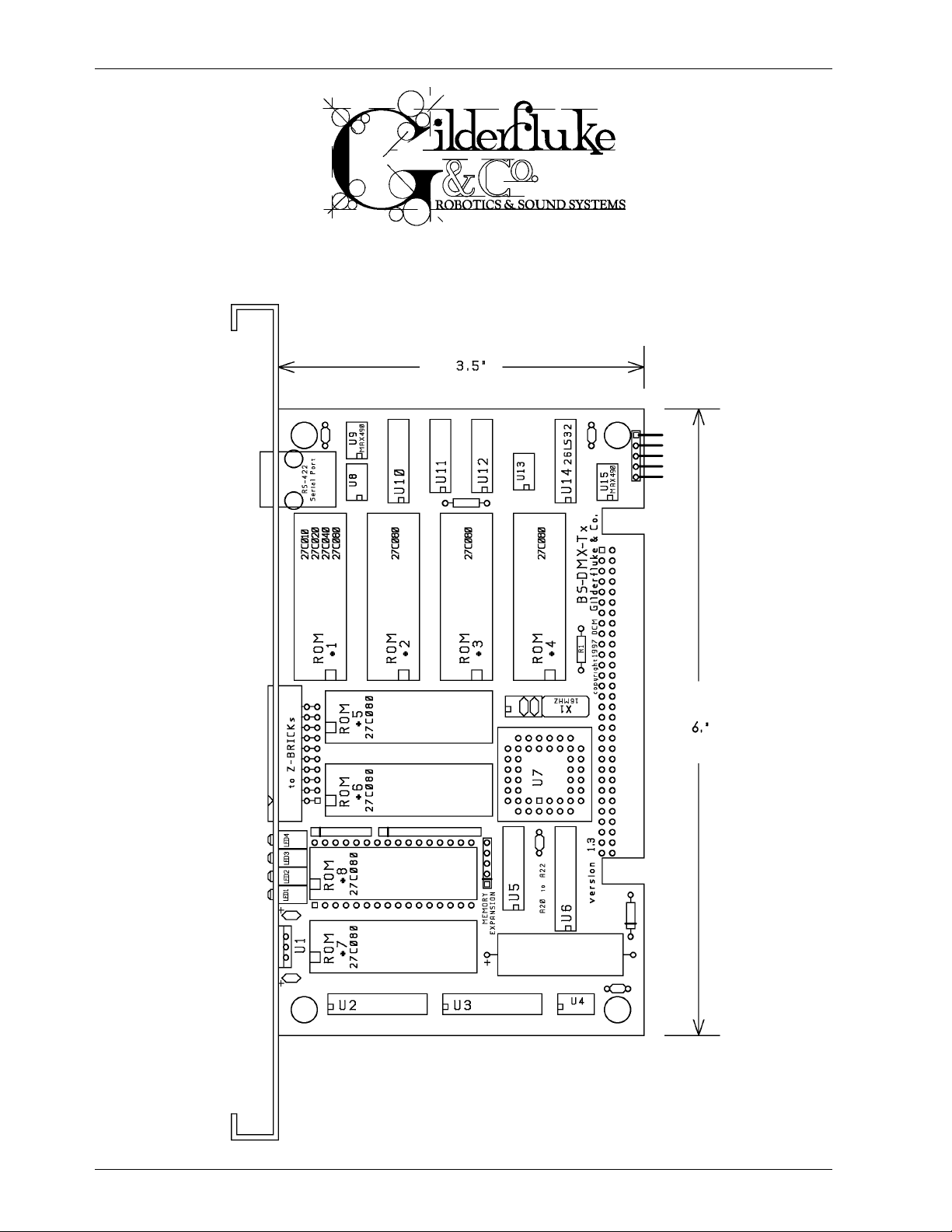
The BS-DMX-Tx or BS-Serial Smart Bricks can be mounted in one 1Ó wide slot in any of our
Brick Card cages. The BS-DMX-Tx or BS-Serial Smart Bricks can be used in conjunction with
any selection of Smart Bricks, Smart Brick Brains, Electronic FeedBack (EFB) Smart Bricks and
Z-Bricks in the same card cage. Card cages with one, two, three or sixteen slots are available. The card cages provide all of the connections for power supply, control signals and
7 of 48
Page 8

GILDERFLUKE & CO.¥ 205 S. FLOWER ST. ¥ BURBANK, CA 91502 ¥ 818/840-9484 ¥ 800/776-5972 ¥ FAX 818/840-9485
outputs that any Brick card will need. Several different styles of output connectors are available on the one and two slot card cages. The sixteen slot card cage mounts in seven inches of standard 19Ó rack space (4-1/2 Ò of space behind the panel).
Power requirements for each BS-DMX-Tx or BS-Serial Smart Bricks are 9 to 24 VDC. The BSDMX-Tx or BS-Serial Smart Brick itself draws approximately 200 ma..
The DMX-512 standard was developed by the United States Institute for Theatrical
Technology (USITT) for a high speed (250 KBaud) asynchronous serial data link. Although it
was originally designed for controlling light dimmers, it is now supported by hundreds of
suppliers throughout the world for controlling all kinds of theatrical equipment.
Even though the DMX-512 standard calls for up to 512 channels of data, the DMX
transmission from PC¥MACs is limited to 256 eight bit wide channels. You can address your
DMX-512 compatible output devices to respond to any address between 00 and 255.
Addresses above the 256th are used in PC¥MACs for transmitting a checksum. The BS-DMXTx or BS-Serial Smart Bricks can use this to verify that the data received from PC¥MACs has no
transmission errors in it. If you address a light dimmer or other DMX-512 device to addresses
256 or 257, you will see this verification data displayed as a flickering pattern.
8 of 48
Page 9

GILDERFLUKE & CO.¥ 205 S. FLOWER ST. ¥ BURBANK, CA 91502 ¥ 818/840-9484 ¥ 800/776-5972 ¥ FAX 818/840-9485
On the Front of the BS-DMX-Tx or BS-Serial Smart Bricks:
A) RS-422 Serial Port: This is used to configure the BS-DMX-Tx or BS-Serial Smart Bricks. It is com-
patible with all of the RS-422 Serial Ports used on Gilderfluke & Company products.
The serial data signals from the BS-DMX-Tx or BS-Serial Smart Bricks are brought out on a six
position RJ-11 (modular telephone style connector). Facing the end of the cable with the release latch upwards, its pin out is as follows:
COLOR SIGNAL NAME:
LEFT #1 white Signal Ground
#2 black - Serial data out from card
#3 red + Serial data out from card
#4 green - Serial data in to card
#5 yellow + Serial data in to card
RIGHT #6 blue Ground to force into configuration
PC and Compatible Connections: To cross wire the RS-422 / RS-485 signals from the BSDMX-Tx or BS-Serial Smart Bricks to the RS-232 serial port of an IBM compatible, cross connect
the signals as follows:
DB-25 DE-9 Signal Signal from/to BS-DMX-Tx/BS-Serial Bricks
2 3 DATA OUT - Serial data into card (#4 green)
3 2 DATA IN - Serial data out from card (#2 black)
7 5 GROUND Signal Ground (#1 white or #6 blue)
Apple Macintosh Connections: Apple Macintosh computers have true RS-422 serial ports
built in. To connect to the BS-DMX-Tx or BS-Serial Smart Bricks, the pin out is as follows (view is of
male connector facing the end of the cable):
The BS-DMX-Tx or BS-Serial Smart Bricks expect to see the serial data in the following format:
ONE START BIT
EIGHT DATA BITS
ONE STOP BIT
Unlike many of the products manufactured by Gilderfluke & Company, the BS-DMX-Tx or
BS-Serial Smart Bricks will enter configuration immediately upon when the sixth wire is grounded. The serial port connection on the front of the BS-DMX-Tx or BS-Serial are not connected to
the standard serial port buss used on the backplanes by BS-ANA, BS-BRN and other Gilderfluke
Cards. Configuration is always done at 9600 baud, no parity, 8 bits, one stop bit.
B) Board Error LED: This LED will flash when:
1) BS-DMX-Tx or BS-Serial Smart Brick just booted
2) An error is found in the DMX-512 data checksum (if receiving DMX-512 data). If this
and the DMX-512 LEDs donÕt turn off, then you are probably sending a DMX-512
stream to the card that doesnÕt have a checksum in it.
3) An error is found in the Smart Brick Network checksum (if receiving Smart Brick Network
data)
C) DMX-512 LED: This LED will be lit when the BS-DMX-Tx or BS-Serial Smart Bricks is receiving DMX-
512 data.
D) Brick Heart: The heartbeat from the Smart Brick Brain is transmitted throughout the system
over the Smart Brick Network. The presence of a healthy heartbeat means that the data on
the Smart Brick Network is getting through cleanly. If it ever stutters or flashes erratically (or not
at all), then there is a problem with the Smart Brick Brain, the Smart Brick Network, or the BSDMX-Tx or BS-Serial Smart Bricks. As the DMX-512 takes precedence over the Smart Brick
Network, this LED will go dark whenever a DMX-512 signal is present.
E) Heartbeat: This LED Flashes continuously while the CPU is running. If it ever stops for more than
a fraction of a second, the 'Deadman' circuit in the BS-DMX-Tx or BS-Serial Smart Bricks will au-
9 of 48
Page 10

GILDERFLUKE & CO.¥ 205 S. FLOWER ST. ¥ BURBANK, CA 91502 ¥ 818/840-9484 ¥ 800/776-5972 ¥ FAX 818/840-9485
tomatically reset the CPU. While performing an Ease-In, the heart rate will double.
F) Z-Brick: This twenty pin IDS connector is used to connect to one or more Z-Bricks. When en-
abled, the BS-DMX-Tx or BS-Serial Smart Bricks puts out data from the DMX-512 input or onboard Eprom to this connector. The format of the data is as follows:
IDS pin # SIGNAL
1 Data bit 0
2 Data bit 1
3 Data bit 2
4 Data bit 3
5 Data bit 4
6 Data bit 5
7 Data bit 6
8 Data bit 7
9 Address bit 0
10 Address bit 1
11 Address bit 2
12 Address bit 3
13 Address bit 4
14 Address bit 5
15 Address bit 6
16 Address bit 7
17 ground
18 ground
19 Strobe/
20 Reset/
When the address and data lines are valid, the rising edge of the Strobe line will latch the
data into the addressed outputs.
10 of 48
Page 11

GILDERFLUKE & CO.¥ 205 S. FLOWER ST. ¥ BURBANK, CA 91502 ¥ 818/840-9484 ¥ 800/776-5972 ¥ FAX 818/840-9485
BackPlane Connections:
The BackPlane connection is through a sixty position double sided edge connector (thirty connections
on each side on .1Ó centers). This normally is plugged into a card cage, but can also be used with an IDS
or other discrete edge connector.
The first ten positions are used for the Smart Brick network and RS-422 serial port used by other cards in
the system. They are normally bussed between all of the cards in the card cage (although they can be
separated by cutting the lines if desired). The BS-DMX-Tx and BS-Serial do not use these bussed serial port
lines.
The next forty positions are used to connect the BS-DMX-Tx or BS-Serial Smart Bricks to the output cabling. It is on these pins that most of the I/O connections are made.
The last ten positions are used to provide power to the BS-DMX-Tx or BS-Serial Smart Bricks. These wires
are ganged to provide a higher current carrying capacity. The pinout of this connector is as follows:
output wire # Edge pin #color wire function
Smart Brick net #2 1 black Smart Brick Network Data/ into BS-DMX-Tx or BS-Serial Smart Bricks
Smart Brick net #1 2 white Smart Brick Network Data into BS-DMX-Tx or BS-Serial Smart Bricks
Smart Brick net #3 3 red Smart Brick Network Clock into BS-DMX-Tx or BS-Serial Smart Bricks
Serial Port #3 4 red TxD + out (not used by BS-DMX-Tx or BS-Serial Smart Bricks)
Smart Brick net #4 5 green Smart Brick Network Clock/ into BS-DMX-Tx or BS-Serial Smart Bricks
Serial Port #2 6 black TxD - out (not used by BS-DMX-Tx or BS-Serial Smart Bricks)
Smart Brick net #5 7 yellow Smart Brick Network Strobe into BS-DMX-Tx or BS-Serial Smart Bricks
Serial Port #5 8 yellow Rx + in (not used by BS-DMX-Tx or BS-Serial Smart Bricks)
Smart Brick net #6 9 blue Smart Brick Network Strobe into BS-DMX-Tx or BS-Serial Smart Bricks
Serial Port #4 10 green Rx -in (not used by BS-DMX-Tx or BS-Serial Smart Bricks)
Ribbon cable #1 11 brown DMX-512 ground
Ribbon cable #2 12 red DMX-512 Rx - into BS-DMX-Tx or BS-Serial Smart Bricks
Ribbon cable #3 13 orange DMX-512 Rx + into BS-DMX-Tx or BS-Serial Smart Bricks
Ribbon cable #4 14 yellow DMX-512 Tx - out of BS-DMX-Tx or BS-Serial Smart Bricks
Ribbon cable #5 15 green DMX-512 Tx + out of BS-DMX-Tx or BS-Serial Smart Bricks
Ribbon cable #6 16 blue
Ribbon cable #7 17 violet
Ribbon cable #8 18 gray
Ribbon cable #9 19 white
Ribbon cable #10 20 black
Ribbon cable #11 21 brown RS-422 ground
Ribbon cable #12 22 red RS-422 Serial Port Rx - data into BS-DMX-Tx or BS-Serial Smart Bricks
Ribbon cable #13 23 orange RS-422 Serial Port Rx + data into BS-DMX-Tx or BS-Serial Smart Bricks
Ribbon cable #14 24 yellow RS-422 Serial Port Tx - data out of BS-DMX-Tx or BS-Serial
Ribbon cable #15 25 green RS-422 Serial Port Tx + data out of BS-DMX-Tx or BS-Serial
Ribbon cable #16 26 blue Ground to force BS-DMX-Tx or BS-Serial into configuration mode
Ribbon cable #17 27 violet Ground to force BS-DMX-Tx or BS-Serial into configuration mode
Ribbon cable #18 28 gray
Ribbon cable #19 29 white
Ribbon cable #20 30 black
Ribbon cable #21 31 brown MIDI n/c (MIDI DIN pin #3)
Ribbon cable #22 32 red MIDI Tx - (MIDI DIN pin #5)
Ribbon cable #23 33 orange MIDI ground (MIDI DIN pin #2)
Ribbon cable #24 34 yellow MIDI Tx + (MIDI DIN pin #4)
Ribbon cable #25 35 green MIDI n/c (MIDI DIN pin #1)
1
1
Errata: These pinouts were reversed in earlier editions of this manual. The pinout shown now has been
corrected. The Left side pin of R1 must be connected to GROUNDÊon the BS-Serial. This is the leftmost of
the two holes it can go into.
11 of 48
Page 12

GILDERFLUKE & CO.¥ 205 S. FLOWER ST. ¥ BURBANK, CA 91502 ¥ 818/840-9484 ¥ 800/776-5972 ¥ FAX 818/840-9485
Ribbon cable #26 36 blue
Ribbon cable #27 37 violet
Ribbon cable #28 38 gray
Ribbon cable #29 39 white
Ribbon cable #30 40 black
Ribbon cable #31 41 brown
Ribbon cable #32 42 red
Ribbon cable #33 43 orange
Ribbon cable #34 44 yellow
Ribbon cable #35 45 green
Ribbon cable #36 46 blue
Ribbon cable #37 47 violet
Ribbon cable #38 48 gray
Ribbon cable #39 49 white
Ribbon cable #40 50 black
n/a 51 black power supply ground
n/a 52 black power supply ground
n/a 53 black power supply ground
n/a 54 black power supply ground
n/a 55 black power supply ground
n/a 56 red + power supply input
n/a 57 red + power supply input
n/a 58 red + power supply input
n/a 59 red + power supply input
n/a 60 red + power supply input
12 of 48
Page 13

GILDERFLUKE & CO.¥ 205 S. FLOWER ST. ¥ BURBANK, CA 91502 ¥ 818/840-9484 ¥ 800/776-5972 ¥ FAX 818/840-9485
Animation Data Eproms:
The Eproms used for all all of the 'Brick' products manufactured by Gilderfluke & Company have traditionally each contained one channel (eight bits) worth of data. The Eproms used on the BS-DMX-Tx or BSSerial Smart Bricks, BS-ANA, EFB Smart Brick and RTU/FSK Units for storing animation data each carry a number of channel's worth of data. The first four bytes also contain the frame rate, number of channels and
the length of the first show in the Eprom.
These are generated on a PC¥MACs system by:
1) Selecting the 'Save as Eprom...' command from the 'File' pulldown.
2) Check on the 'Multi Channel' checkbox
3) Set the 'start' and 'end' boxes to set the number channels you want to go into this multiple
Eprom file. A BS-DMX-Tx or BS-Serial Smart Bricks can hold anywhere from one to all 255 channels. Be sure to allow for enough extra channels for any Z-Bricks that might be attached to the
BS-DMX-Tx or BS-Serial Smart Bricks. When creating Eproms for a BS-DMX-Tx, the ÔstartÕ is usually
set to Ô00Õ. When preparing Eproms for a BS-Serial, the ÔstartÕ can be set to any value. The ÔFirst
Address in EpromÕ value is set to equal the ÔstartÕ value that is used when creating the Eprom
files.
4) Use the ÔAddÕ button to select any additional show you would like to be saved into this Eprom
file set.
5) Use the ÔPromoteÕ and ÔDemoteÕ buttons to move selected show(s) into the order you would like
to save them in the Eprom.
6) Normally you will want to select the ÔCalculate Brick Start FramesÕ checkbox to allow PC¥MACs
to automatically calculate the offset into the Eproms needed for the shows you are saving. If
you would like to preserve the ÔStart frameÕ values in the show files, also check the ÔSave Brick
StartsÕ checkbox.
7) If you are not using the PC¥MACs calculated ÔBrick StartsÕ, you will have had to set these individually for each show under its File/Show Information dialog. If they are set improperly,
PC¥MACs will tell you if any of the shows are overlapping during the build. When using ÔBrick
StartsÕ that you have entered, PC¥MACs can pad the space between the shows with the default values for the movements if you have checked the ÔPad With Default ValuesÕ checkbox.
8) Press the ÔBuildÕ button to begin the saving process. A standard file save dialog will open.
Name the file as desired. (it defaults to the name of the first show in the list). PC¥MACs will
warn you if a file already exists with this name. Hit OK to save the data to a file.
Once the shows have been saved to the multiple show file, you can burn them into Eprom(s) using
any Eprom programmer that supports 27C010 through 27C080 Eproms. The BS-DMX-Tx or BS-Serial Smart
Bricks each hold a single 27C010, 27C020 or 27C040. If using 27C080 Eproms, you can use up to eight
of these chips on each BS-DMX-Tx or BS-Serial Smart Brick. If more than eight 27C080s are needed, then a
memory expansion card can add the capacity for a total of up to fifteen 27C080 Eproms or a single PCMCIA flash card.
If you press the ÔReportÕ button, PC¥MACs will display the information about the Eprom set you just
saved. This information is also saved in a text file with the same name as the Eproms, but with the extension of Ô.setÕ. You can open this file with any text editor like Notepad or Wordpad. The numbers shown for
ÔBrick startÕ and ÔBrick endÕ are what you need to enter into the Smart Brick Brain to set the start and end of
each show. The ÔEprom startÕ and ÔEprom endÕ are the actual locations of the shows in the Eprom set. The
number shown for the ÔEprom EndÕ for the last show in this file set is the last byte which will be saved into
the Eprom. If your Eprom is smaller than this number, you will need to use more than a single Eprom. The
capacities of all of the large Eproms are as follows:
13 of 48
Page 14

GILDERFLUKE & CO.¥ 205 S. FLOWER ST. ¥ BURBANK, CA 91502 ¥ 818/840-9484 ¥ 800/776-5972 ¥ FAX 818/840-9485
Eprom type Total number of bytes
27C010 131,072
27C020 262,144
27C040 524,288
27C080 1,048,576
Note that at least one show must be loaded starting at a 'Brick Start' of 0, even if it is only a frame or
two long. PC¥MACs will use this first show to set the frame rate and number of channels stored in the multiple channel Eprom. The BS-DMX-Tx or BS-Serial Smart Brick need this information to index into the Eprom.
If the data sent out from an Eprom BS-DMX-Tx or BS-Serial has shifted compared to what you saw when
you were sending the card DMX data, It is an indication that the ÔstartÕ was set improperly when the Eprom
file set was saved. On a BS-DMX-Tx, the first byte of data in the Eprom is output in DMX-Channel Ô00Õ. When
saving the Eprom from PC¥MACs, always set the ÔStart ChannelÕ to Ô00Õ. The channels output will then be
exactly what you saw when you were programming.
On the BS-Serial, the offset is a question of the address set for the ÔFirst Address in EpromÕ and the
channel used for the ÔStart ChannelÕ when saving the Eproms from PC¥MACs. The EpromsÕ data can start
at any ÔStart ChannelÕ that you would like. Data from the Eprom will be offset by the ÔFirst Address in EpromÕ
value. These two should be set to the same value if you want the data to appear as it was when you were
programming. DMX-512 devices and Z-Bricks that are addressed below the ÔFirst Address in EpromÕ will receive Ô00Õ values, as will any addresses after the end of the data in the Eprom(s).
14 of 48
Page 15

GILDERFLUKE & CO.¥ 205 S. FLOWER ST. ¥ BURBANK, CA 91502 ¥ 818/840-9484 ¥ 800/776-5972 ¥ FAX 818/840-9485
BS-DMX-Tx or BS-Serial Smart Bricks Configuration:
To communicate with the BS-DMX-Tx or BS-Serial Smart Bricks through the serial port, you can use just
about any computer or terminal which has a serial port on it. Some newer computer designs, like the
Apple Macintosh, come with serial ports which are directly compatible with the RS-422 / RS-485 signal levels the BS-DMX-Tx or BS-Serial Smart Bricks wants to see. These signal levels are close enough to be used
with the RS-232 signal levels found on most older computers (like most IBMs and compatibles) with only a
simple adapter cable, so long as the wire isn't too long. To gain the full advantage of the RS-422 / RS-485
signal levels you will need to use a signal level adapter like our 232conv-09.
If you are using a computer as a terminal you will need to run a modem or terminal emulation program. These will send everything you type on the keyboard out the serial port on your computer while
printing on the screen anything which comes in from the BS-DMX-Tx or BS-Serial Smart Bricks through the
serial port. Every copy of Windows 3.1 comes with TERM.EXE, which is just such a program. Windows Ô95 &
Windows Ô98 comes with a (not quite as good) terminal program called ÔHyper TermÕ 2. Z-Term is available
as shareware (free) from most bulletin board systems and users groups for Macintosh computers. A
modem program will usually have the advantage over a terminal emulation program in that it will allow
you to save data to your computer's disk drives and then send it back to the BS-DMX-Tx or BS-Serial Smart
Bricks at a later date. The BS-DMX-Tx or BS-Serial Smart Bricks uses no screen control codes or ESCape sequences (unless VT-52 compatible mode has been enabled), so it should work on any machine with an
eighty column by twenty-four line display. Machines with other display formats will work, but may not look
so neat on the screen.
When configuring your modem program, you should set it for 9600 baud, 8 data bits, one stop bit and
no parity. If your terminal emulation program supports VT-52 terminal emulation (they all do!), you should
enable it. This will allow faster screen redraws if 'VT-52 compatible' mode is enabled on the BS-DMX-Tx or
BS-Serial Smart Bricks. You should set your program NOT to insert an extra LineFeed (LF) character after
each Carriage Return (CR) it receives. You should also tell it NOT to scroll automatically after the eightieth
column is filled. If either of these are on, the screen will be displayed 'double spaced'. This won't cause
any problem, but may make it hard to see the whole screen at one time.
If you have hooked up the BS-DMX-Tx or BS-Serial Smart Bricks to your computer and it still doesn't seem
to respond to the keyboard, the first thing to check is that you are attached to the right serial port. The
easiest way to do this is to disconnect the BS-DMX-Tx or BS-Serial Smart Bricks and short between the Tx
data out and Rx data in pins on the serial port connector on the back of your computer. On all IBMs and
compatibles this means sticking a piece of wire, paper clip, or similar tool between pins 2 and 3 on the
'Com.' connector. While still running the modem program, anything you type should be shown on the
screen while this paper clip is in place, while nothing will appear when you remove it. If your computer
passes this test, then you are using the right serial port and the problem is most likely the baud rate setting
or in your wiring to the BS-DMX-Tx or BS-Serial Smart Bricks. If you get characters on the screen even with
the paper clip removed from the serial port, it means you probably need to set the 'echo' mode to 'none'
or 'full duplex' and try this test again.
To enter the configuration mode on a BS-DMX-Tx or BS-Serial Smart Brick, you need to ground the pin
shown on the connection diagrams. This can be done on the backplane or the connector on the front of
the card. Plugging in a six conductor modular cable from a Gilderfluke & Company RS-232 to RS-422 converter will automatically do this for you and put the card into configuration mode.
Configuration mode uses the same serial port as any string or other special outputs. Entering configuration mode will immediately stop the normal serial port outputs, force the card to 9600 baud, no parity,
eight data bits and one stop bit.
All numeric values in configuration mode are entered in HEXadecimal (0-9, A through F) or Decimal
numbers (0-9), as selected on the menu. Each number consist of one or more ASCII characters followed
by a <RETURN> (<ENTER> on some keyboards). If more characters have been entered before the <RETURN> than are allowed, then the characters already entered will scroll to the left to make room for the
new entries. Once a command has been invoked, characters can be erased one-by-one by using the
<DELETE> key (<BACKSPACE> on some keyboards). An entire entry can be erased by hitting the
<ESC>ape key. A command can be canceled altogether by hitting the <RETURN> key (<ENTER> on
2
If possible, copy Ôterm.exeÕ from your older PC and put it onto your Windows Ô95 or Windows Ô98
machine. After all, you probably already own it.
15 of 48
Page 16

GILDERFLUKE & CO.¥ 205 S. FLOWER ST. ¥ BURBANK, CA 91502 ¥ 818/840-9484 ¥ 800/776-5972 ¥ FAX 818/840-9485
some keyboards) or <ESC>ape key after all of the characters have been erased or before any have been
entered.
If you want to keep a hard copy printout of the current configuration of the BS-DMX-Tx or BS-Serial
Smart Bricks, you should use the <ESC>ape key to redraw the screen while saving the print in the modem
program running on your computer. This file can then be printed out at any time.
To redraw the screen at any time, just press the <ESC>ape key or <SPACE> bar.
16 of 48
Page 17

GILDERFLUKE & CO.¥ 205 S. FLOWER ST. ¥ BURBANK, CA 91502 ¥ 818/840-9484 ¥ 800/776-5972 ¥ FAX 818/840-9485
BS-DMX-Tx
For a BS-DMX-Tx, the menu will appear as follows. There are no serial commands available on the BSDMX-Tx. The menu just allows you to see what sized Eprom (if any) is installed. If no Eprom is found, the Ônot
foundÕ will appear in the place of the Eprom size.
-Gilderfluke & Company - DMX Output Smart Brick - ver 1.00 - copyright 1999 DCM-
EPROM: 18h channels @ 30 FPS / first show is 005Ah frames long
Enter Command-
DMX-512 data is always transmitted from the BS-DMX-Tx starting at DMX address zero. When you save
the file to be programmed into the Eprom, be aware that no matter what ÔstartÕ address is used, the first
channel will come out of the BS-DMX-Tx at address zero.
17 of 48
Page 18

GILDERFLUKE & CO.¥ 205 S. FLOWER ST. ¥ BURBANK, CA 91502 ¥ 818/840-9484 ¥ 800/776-5972 ¥ FAX 818/840-9485
BS-Serial in MIDI Mode
For a BS-Serial in MIDI mode, the menu will appear as follows. If an Eprom is found, the size of the first
show is displayed at the top of the screen. If no Eprom is found, the Ônot foundÕ will appear in the place of
the show size:
-Gilderfluke & Company - Serial Output Smart Brick - v1.05 - copyright 1999 DCM-
EPROM: 123 channels @ 30 FPS / first show is 12345 frames long
a) 1st address in Eprom- _10
b) baud rate- 9600 baud
c) DMX Rx checksums- yes
d) sequencer enabled- yes
e) frame rate divided/2- no
f) numbering system- decimal
g) VT-52 display- yes
h) operating mode- MIDI (set baud rate for MIDI!)
i) monitor channel- _10
j) MIDI keyboard channels- _11 thru _26
k) voice- 01, press vel- _64, release vel- _64
l) string trigger channel- _27
m) edit strings...
o) reload defaults....
r) download configuration....
Enter Command-
a) First Addressed in Eprom: Any DMX-512 data that is sent to the BS-Serial will be passed
through at the same address at which it was received. This command is used to offset the
data from the on-board Eproms to match the addresses that were used when you were programming. As an example, if the outputs you are using start at 10, then you need to create
the Eprom files set starting with a ÔstartÕ of 10 in the PC¥MACs program. When playing back
from the BS-Serial, the data will need to be offset to Ô10Õ so that the channels are reproduced
at the same locations where they were when you were programming.
b) Baud Rate: This command sets the speed at which serial data is sent out of the BS-SerialÕs seri-
al port when the card isnÕt in configuration mode. The baud rates available on the BS-Serial
are:
1) MIDI baud rate (31,250 baud)
2) 2400 baud
3) 4800 baud
4) 9600 baud
5) 19.2 KBaud
6) 38.4 KBaud
7) 57.6 KBaud
8) 115.2 KBaud
The baud rate must be set to match the device you are trying to talk to. In the case of
MIDIÊ devices, you need to make sure that the baud rate has been set to ÔMIDIÕ. As in the
screen above, the BS-Serial will warn you if the baud rate has not been set properly. No matter
what baud rate you select here, the configuration mode will always run at 9600 baud.
c) DMX Rx Checksum: This toggle is used to enable and disable the error checking in data re-
ceived through the DMX-512 data input. Without it, the BS-Serial Smart Brick won't be able to
recognize errors in the incoming data, and may update the outputs with this bad data. It
should be left ON whenever running from a PC¥MACs or other DMX-512 source that supports
this checksum. All Gilderfluke & Company send this checksum. If this toggle is ON and the
18 of 48
Page 19

GILDERFLUKE & CO.¥ 205 S. FLOWER ST. ¥ BURBANK, CA 91502 ¥ 818/840-9484 ¥ 800/776-5972 ¥ FAX 818/840-9485
DMX-512 data received doesnÕt have the checksum in it, both the DMX LED and the ÔBoard
ErrorÕ LED will be ON.
d) Sequencer Enabled: This toggle enables and disables the BS-Serial Smart Brick to use the
Animation Data Eprom. When it is OFF, nothing will be output even when the Smart Brick
Network is active. If it is ON, then the data from the Animation Data Eprom will be sent out
when the Smart Brick Network is active unless the BS-Serial is receiving DMX-512 data, which
takes precedence.
e) Frame Rate /2: This toggle is used to drop the frame rate of the data being played back from
the Eproms or DMX-512 by half. This cuts the number of messages that are sent out the serial
and DMX-512 ports by half. When controlling many serial devices, the limiting factor in the
number of channels that can be controlled is often the amount of data you can jam through
at the highest supported baud rates. A secondary advantage of slowing the frame rate by half
is that the same sized Eprom can then hold twice the time as it otherwise could.
When this feature is used, the main part of the show is typically run at thirty FPS and the
outputs from the BS-Serial will update at fifteen FPS. The show that is used to generate the
Eprom data for a slowed BS-Serial Smart Bricks should be programmed at half the rate of the
rest of the show. This is done by programming the show as normal, saving a duplicate, and
then using the ÔShow InformationÕ dialog to drop the frame rate by half.
f) Numbering System: This toggle is used to select between HEXadecimal or Decimal numbering
systems for display and entries.
g) VT-52 Compatible Display: When this toggle is enabled, the BS-DMX-Tx or BS-Serial Smart Bricks
will use special escape sequences to clear the screen (<ESC>ape 'E'), clear the current line
(<ESC>ape 'l'), or position the cursor (<ESC>ape 'Y' ROW COLUMN). When disabled, the BSDMX-Tx or BS-Serial Smart Bricks has to redraw the entire screen to change any value, so it can
save a good deal of screen redraw time if you have a compatible display.
h) Operating Mode: This command us used to toggle through all of the modes that are available
to you on the BS-Serial. If you are just using the BS-Serial for sending serial strings or DMX-512
data, just leave the card in MIDI mode and donÕt set up any of the MIDI-Specific commands.
As of this writing, the modes available on the BS-Serial are:
1) MIDI: Sends MIDI key on and key off commands
2) Intelix: Sends strings to control Intelix brand matrix mixers
3) Rexroth quick write: Supports serial control of Mannesmann Rexroth DCC Servo cards
4) Orpan (LSB first): One of two modes to support serial control of Orpan motion bases
5) Orpan (MSB first): One of two modes to support serial control of Orpan motion bases
6) Moog / DOF mode: One of two modes to support serial control of Moog electric motion bases
7) Moog / length mode: One of two modes to support serial control of Moog electric motion bases
i) Monitor Channel: This command is used to select a channel that is used to build up a serial
string byte-by-byte from the animation data, and then send it out at the appropriate time. It
can be used to send any ÔspecialÕ commands you might need to send to the equipment
being controlled by the BS-Serial. Any string of any length up to 256 bytes can be built up and
sent using this feature. It is typically used to send commands to the serially controlled equipment that doesnÕt need to be sent regularly. Typical of these commands are initialization and
de-initialization strings.
This command asks for the address of an eight bit value in the animation data. If you enter
an address of 255/0FFh, this feature will be disabled. Once set (and configuration mode exited), the BS-Serial will begin monitoring this location for any non-zero values. Once it finds one
non-zero value, it starts buffering whatever values it finds in this location in each subsequent
frame of animation data into a buffer. If it then finds two consecutive frames of animation
data with a zero value in them, it will then immediately send out the entire string that has
been built up.
The advantage of using this mode of sending strings is that any string can be built up and
19 of 48
Page 20

GILDERFLUKE & CO.¥ 205 S. FLOWER ST. ¥ BURBANK, CA 91502 ¥ 818/840-9484 ¥ 800/776-5972 ¥ FAX 818/840-9485
sent from the animation data. The disadvantage of this feature is that it takes as one frame of
time for each entry ion the string to be buffered in before it can be sent. A 200 character
long string will take 202 frames of data to build up and send out. This translates to almost
seven seconds at 30 FPS.
Data for these strings is typically hand entered using PC¥MACsÕ OffLine editing tools. The
target channel may be defined as either a single eight bit analog or as eight separate digital
functions within the same byte. If it is defined as an analog, you can use the ÔSet to a Value...Õ
commands to enter each frame of the string (be sure to turn off the ÔCut/PasteÕ options under
the ÔPreferencesÕ pulldown). If it is defined as eight digital channels, you can just draw in the
binary data as needed.
j) MIDIÊ Keyboard Channels: This is a MIDI Mode specific command. MIDI was designed for
sending data from electronic keyboards and instruments to one another. This feature allows
you to define sixteen consecutive bytes of animation data (128 digital bits) to emulate a MIDI
keyboard. This command sets the address of the first byte used in this way. The other fifteen
bytes follow immediately. If you set this value to 255/0FFh, this feature is disabled.
Once the address is set using this command and the configuration mode exited, the BSSerial will start monitoring for any changes in these sixteen bytes. Any bit that goes high will
trigger a MIDI Ôkey downÕ string to be sent. any bit that was high and goes low will trigger a MIDI
Ôkey upÕ string.
Normal keyboards only have 88 keys. The 128 digitals monitored by the BS-Serial are
mapped with a standard keyboard right in the middle. Middle ÔCÕ is found on the 60th digital.
This translates to bit four of the seventh byte that is being monitored.
Each of the MIDI key up/key down strings is three bytes long. At the relatively slow 31,250
baud rate MIDI uses (3125 bytes per second), it is possible to overrun the 256 byte long buffer
used for sending data from the BS-Serial. Be aware that the low speed of a MIDI serial stream
means that it will take almost 1/10 of a second to send out 256 bytes of data. The following
are the rules for MIDI:
1) DonÕt make more than 85 key changes on any one frame of animation data. The last
bits wonÕt be turned on or off until almost 1/10th of a second later (3 frames after the
first bit changed, at thirty FPS).
2) You can not send more than 1041 MIDI key up/key down sequences per second.
3) At thirty FPS, the average number of changes on each frame should not exceed 34.
4) MIDI has no error detection or correction built in. There is no guarantee that any command will ever reach the device that the BS-Serial is controlling through a MIDI output.
If a MIDI Ôkey downÕ sequence is missed, the output will remain off until another MIDI
Ôkey downÕ is received for the same output. If a MIDI Ôkey upÕ sequence is missed, the
output will remain stuck on until another MIDI Ôkey upÕ is received for the same output.
Do not use MIDI for any safety related equipment.
5) MIDI wiring standards allow for a MAXIMUM wire length of fifty feet. The longer the wire,
the better are the chances that MIDI messages will be missed or garbled. A MIDI receiver canÕt tell a garbled MIDI message from a perfectly good one.
The above are all shortcomings in the design of any MIDI system. They come directly from
the MIDI standards. These are the reasons why MIDI is not used for any professional animation
control systems.
Just for some contrast, at the typical thirty frames per second that a Gilderfluke Animation
Control System operates at, there is no limitation to the number of digital functions that turn
on or off at one time. With 2048 digitals controls, there can be 2048 on and off events per
frame, or 61,440 on and off events per second. If there is any error in the data stream, the
outputs will not be updated with this bad data and the corrected data will be output on the
next frame (typically 1/30th of a second later). Recommended wire length without any additional hardware is one mile.
k) Voice, Press Velocity, and Release Velocity: This is a MIDI Mode specific command. This
command is used to set which of sixteen possible MIDI ÔinstrumentsÕ the key commands are
20 of 48
Page 21

GILDERFLUKE & CO.¥ 205 S. FLOWER ST. ¥ BURBANK, CA 91502 ¥ 818/840-9484 ¥ 800/776-5972 ¥ FAX 818/840-9485
sent to, and the ÔspeedÕ that is used for the MIDI Ôkey downÕ and Ôkey upÕ commands. The default MIDI ÔspeedÕ is 64. A value of one is the slowest possible key up or down speed. A value of
127 gives the fastest possible key speed. A ÔspeedÕ value of zero will turn off a note, even on a
MIDI Ôkey downÕ message.
l) String Trigger Channel: This command is used to set the address of the eight bit channel that
is used to trigger the strings which are entered using the next command. Setting this value to
255/0FFh will disable this feature.
Any eight bit channel of animation data can be used to trigger the sending of the strings
which are entered using the next command. There are a total of sixteen strings available.
Each bit triggers one string to be sent on the rising edge, and a second completely different
string on the falling edge. This feature is typically used to send strings that need to be sent too
regularly for using the ÔMonitor ChannelÕ feature.
m) Edit Strings.....: This command brings up the following menu. It is used to enter the strings that
are sent when using the ÔString TriggerÕ feature. There are sixteen possible strings. Each string
can be up to eighteen characters long. One is sent on the rising, and a different one is sent
on the falling edge of each of the eight bits in the String Trigger channel.
-Gilderfluke & Company - Serial Output Smart Brick - v1.05 - copyright 1999 DCM-
EPROM: 123 channels @ 30 FPS / first show is 12345 frames long
input 01 02 03 04 05 06 07 08 09 10 11 12 13 14 15 16 17 18
0) 0 ^ |_10|_13|_30|_82|105|115|105|110|103|___|___|___|___|___|___|___|___|___|
1) 1 ^ |_10|_13|_31|_82|105|115|105|110|103|___|___|___|___|___|___|___|___|___|
2) 2 ^ |_10|_13|_32|_82|105|115|105|110|103|___|___|___|___|___|___|___|___|___|
3) 3 ^ |_10|_13|_33|_82|105|115|105|110|103|___|___|___|___|___|___|___|___|___|
4) 4 ^ |_10|_13|_34|_82|105|115|105|110|103|___|___|___|___|___|___|___|___|___|
5) 5 ^ |_10|_13|_35|_82|105|115|105|110|103|___|___|___|___|___|___|___|___|___|
6) 6 ^ |_10|_13|_36|_82|105|115|105|110|103|___|___|___|___|___|___|___|___|___|
7) 7 ^ |_10|_13|_37|_82|105|115|105|110|103|___|___|___|___|___|___|___|___|___|
8) 0 v |_10|_13|_30|_70|_97|108|108|105|110|103|___|___|___|___|___|___|___|___|
9) 1 v |_10|_13|_31|_70|_97|108|108|105|110|103|___|___|___|___|___|___|___|___|
A) 2 v |_10|_13|_32|_70|_97|108|108|105|110|103|___|___|___|___|___|___|___|___|
B) 3 v |_10|_13|_33|_70|_97|108|108|105|110|103|___|___|___|___|___|___|___|___|
C) 4 v |_10|_13|_34|_70|_97|108|108|105|110|103|___|___|___|___|___|___|___|___|
D) 5 v |_10|_13|_35|_70|_97|108|108|105|110|103|___|___|___|___|___|___|___|___|
E) 6 v |_10|_13|_36|_70|_97|108|108|105|110|103|___|___|___|___|___|___|___|___|
F) 7 v |_10|_13|_37|_70|_97|108|108|105|110|103|___|___|___|___|___|___|___|___|
enter number of string to edit, or <ESC>ape to return to main menu (0-F)-
In the example above, the strings have been set to send out strings that display the bit
number and the word ÔRisingÕ or ÔFallingÕ.
u) Download configuration: This command is used to save the current configuration of the BS-
Serial Smart Brick through the serial port to a file on your computer. This file can then be
reloaded into this, or any other BS-Serial Smart Brick. To use this command, you first invoke it,
then following the instructions, you set your computer to receive a string of ASCII characters.
You then press any key to tell the BS-Serial Smart Brick to send out it's configuration. When it
has finished, you then tell your computer to stop saving characters, and then hit any key to
tell the BS-Serial Smart Brick to redraw the screen.
o) Reload Default Configuration: This command reloads the default configuration to the BS-
Serial Smart Brick. This will overwrite any configuration data which was in the BS-Serial.
s) Upload configuration: This command (which doesn't appear on the menu) is the compliment
of the Download Configuration command. To invoke it, all you need to do is tell your modem
program to send the file saved by the 'download' command back to the BS-Serial Smart Brick.
This will automatically invoke the upload command and store the incoming data.
21 of 48
Page 22

GILDERFLUKE & CO.¥ 205 S. FLOWER ST. ¥ BURBANK, CA 91502 ¥ 818/840-9484 ¥ 800/776-5972 ¥ FAX 818/840-9485
+) Data Dump: This command (which doesn't appear on the menu) dumps out the DMX output
buffer and the configuration memory onto the screen. This started as some developmental
routines, and there was plenty of space available, so what the hell.
22 of 48
Page 23

GILDERFLUKE & CO.¥ 205 S. FLOWER ST. ¥ BURBANK, CA 91502 ¥ 818/840-9484 ¥ 800/776-5972 ¥ FAX 818/840-9485
BS-Serial in Intelix Mode
For a BS-Serial in Intelix mode, the menu will appear as follows. If an Eprom is found, the size of the first
show is displayed at the top of the screen. If no Eprom is found, the Ônot foundÕ will appear in the place of
the show size:
-Gilderfluke & Company - Serial Output Smart Brick - v1.05 - copyright 1999 DCM-
EPROM: 123 channels @ 30 FPS / first show is 12345 frames long
a) 1st address in Eprom- _10
b) baud rate- 38.4Kbaud
c) DMX Rx checksums- yes
d) sequencer enabled- yes
e) frame rate divided/2- no
f) numbering system- decimal
g) VT-52 display- yes
h) operating mode- Intelix
i) monitor channel- _10
j) Intelix strings....
l) string trigger channel- _11
m) edit strings....
o) reload defaults....
r) download configuration....
Enter Command-
a) First Addressed in Eprom: Any DMX-512 data that is sent to the BS-Serial will be passed
through at the same address at which it was received. This command is used to offset the
data from the on-board Eproms to match the addresses that were used when you were programming. As an example, if the outputs you are using start at 10, then you need to create
the Eprom files set starting with a ÔstartÕ of 10 in the PC¥MACs program. When playing back
from the BS-Serial, the data will need to be offset to Ô10Õ so that the channels are reproduced
at the same locations where they were when you were programming.
b) Baud Rate: This command sets the speed at which serial data is sent out of the BS-SerialÕs seri-
al port when the card isnÕt in configuration mode. The baud rates available on the BS-Serial
are:
1) MIDI baud rate (31,250 baud)
2) 2400 baud
3) 4800 baud
4) 9600 baud
5) 19.2 KBaud
6) 38.4 KBaud
7) 57.6 KBaud
8) 115.2 KBaud
The baud rate must be set to match the device you are trying to talk to. The highest speed
supported by the Intelix Matrix Mixers is 38.4 KBaud. This is the speed that should be used when
in Intelix mode. No matter what baud rate you select here, the configuration mode will always
run at 9600 baud.
c) DMX Rx Checksum: This toggle is used to enable and disable the error checking in data re-
ceived through the DMX-512 data input. Without it, the BS-Serial Smart Brick won't be able to
recognize errors in the incoming data, and may update the outputs with this bad data. It
should be left ON whenever running from a PC¥MACs or other DMX-512 source that supports
this checksum. All Gilderfluke & Company send this checksum. If this toggle is ON and the
23 of 48
Page 24

GILDERFLUKE & CO.¥ 205 S. FLOWER ST. ¥ BURBANK, CA 91502 ¥ 818/840-9484 ¥ 800/776-5972 ¥ FAX 818/840-9485
DMX-512 data received doesnÕt have the checksum in it, both the DMX LED and the ÔBoard
ErrorÕ LED will be ON.
d) Sequencer Enabled: This toggle enables and disables the BS-Serial Smart Brick to use the
Animation Data Eprom. When it is OFF, nothing will be output even when the Smart Brick
Network is active. If it is ON, then the data from the Animation Data Eprom will be sent out
when the Smart Brick Network is active unless the BS-Serial is receiving DMX-512 data, which
takes precedence.
e) Frame Rate /2: This toggle is used to drop the frame rate of the data being played back from
the Eproms or DMX-512 by half. This cuts the number of messages that are sent out the serial
and DMX-512 ports by half. When controlling many serial devices, the limiting factor in the
number of channels that can be controlled is often the amount of data you can jam through
at the highest supported baud rates. A secondary advantage of slowing the frame rate by half
is that the same sized Eprom can then hold twice the time as it otherwise could.
When this feature is used, the main part of the show is typically run at thirty FPS and the
outputs from the BS-Serial will update at fifteen FPS. The show that is used to generate the
Eprom data for a slowed BS-Serial Smart Bricks should be programmed at half the rate of the
rest of the show. This is done by programming the show as normal, saving a duplicate, and
then using the ÔShow InformationÕ dialog to drop the frame rate by half.
f) Numbering System: This toggle is used to select between HEXadecimal or Decimal numbering
systems for display and entries.
g) VT-52 Compatible Display: When this toggle is enabled, the BS-DMX-Tx or BS-Serial Smart Bricks
will use special escape sequences to clear the screen (<ESC>ape 'E'), clear the current line
(<ESC>ape 'l'), or position the cursor (<ESC>ape 'Y' ROW COLUMN). When disabled, the BSDMX-Tx or BS-Serial Smart Bricks has to redraw the entire screen to change any value, so it can
save a good deal of screen redraw time if you have a compatible display.
h) Operating Mode: This command us used to toggle through all of the modes that are available
to you on the BS-Serial. If you are just using the BS-Serial for sending serial strings or DMX-512
data, just leave the card in MIDI mode and donÕt set up any of the MIDI-Specific commands.
As of this writing, the modes available on the BS-Serial are:
1) MIDI: Sends MIDI key on and key off commands
2) Intelix: Sends strings to control Intelix brand matrix mixers
3) Rexroth quick write: Supports serial control of Mannesmann Rexroth DCC Servo cards
4) Orpan (LSB first): One of two modes to support serial control of Orpan motion bases
5) Orpan (MSB first): One of two modes to support serial control of Orpan motion bases
6) Moog / DOF mode: One of two modes to support serial control of Moog electric motion bases
7) Moog / length mode: One of two modes to support serial control of Moog electric motion bases
i) Monitor Channel: This command is used to select a channel that is used to build up a serial
string byte-by-byte from the animation data, and then send it out at the appropriate time. It
can be used to send any ÔspecialÕ commands you might need to send to the equipment
being controlled by the BS-Serial. Any string of any length up to 256 bytes can be built up and
sent using this feature. It is typically used to send commands to the serially controlled equipment that doesnÕt need to be sent regularly. Typical of these commands are initialization and
de-initialization strings.
This command asks for the address of an eight bit value in the animation data. If you enter
an address of 255/0FFh, this feature will be disabled. Once set (and configuration mode exited), the BS-Serial will begin monitoring this location for any non-zero values. Once it finds one
non-zero value, it starts buffering whatever values it finds in this location in each subsequent
frame of animation data into a buffer. If it then finds two consecutive frames of animation
data with a zero value in them, it will then immediately send out the entire string that has
been built up.
The advantage of using this mode of sending strings is that any string can be built up and
24 of 48
Page 25

GILDERFLUKE & CO.¥ 205 S. FLOWER ST. ¥ BURBANK, CA 91502 ¥ 818/840-9484 ¥ 800/776-5972 ¥ FAX 818/840-9485
sent from the animation data. The disadvantage of this feature is that it takes as one frame of
time for each entry ion the string to be buffered in before it can be sent. A 200 character
long string will take 202 frames of data to build up and send out. This translates to almost
seven seconds at 30 FPS.
Data for these strings is typically hand entered using PC¥MACsÕ OffLine editing tools. The
target channel may be defined as either a single eight bit analog or as eight separate digital
functions within the same byte. If it is defined as an analog, you can use the ÔSet to a Value...Õ
commands to enter each frame of the string (be sure to turn off the ÔCut/PasteÕ options under
the ÔPreferencesÕ pulldown). If it is defined as eight digital channels, you can just draw in the
binary data as needed.
j) Intelix Strings: This is a Intelix Mode specific command. This command is used to set up the
commands that the Intelix Matrix mixer will respond to. The format of all Intelix strings is pretty
similar. The typical string to use with the BS-Serial is the one that adjusts the level of a single
matrix mixer cross point in real time.
In the following example, the audio which is present on input number four is being sent to
output number five. The level of the mix is set by animation channel twenty.
Ô251Õ (header for all commands), Ô0Õ (MSB of command length), Ô5Õ (LSB of command
length), Ô2Õ (class), Ô14 (message I.D.)Õ, 4 (input number), 5 (output number)
Consult the Intelix programming manual for specifics on all other Intelix serial commands.
The Intelix mixer currently supports baud rates of 9600, 19.2 KBaud and 38.4 KBaud. There
is no reason to use anything but the highest rate available. The maximum string length for the
matrix mix commands is eleven bytes. The maximum number of matrix points you should try to
control is eleven when using 38.4 KBaud and thirty FPS. If you use the Ôframe rate /2Õ feature,
you can double this to control twenty-two matrix points simultaneously.
-Gilderfluke & Company - Serial Output Smart Brick - v1.05 - copyright 1999 DCM-
EPROM: 123 channels @ 30 FPS / first show is 12345 frames long
Channel 1 2 3 4 5 6 7 8 9
0) _20 |251|__0|__5|__2|_14|__4|__5|__0|__0|
1) xxx |___|___|___|___|___|___|___|___|___|
2) xxx |___|___|___|___|___|___|___|___|___|
3) xxx |___|___|___|___|___|___|___|___|___|
4) xxx |___|___|___|___|___|___|___|___|___|
5) xxx |___|___|___|___|___|___|___|___|___|
6) xxx |___|___|___|___|___|___|___|___|___|
7) xxx |___|___|___|___|___|___|___|___|___|
8) xxx |___|___|___|___|___|___|___|___|___|
9) xxx |___|___|___|___|___|___|___|___|___|
A) xxx |___|___|___|___|___|___|___|___|___|
B) xxx |___|___|___|___|___|___|___|___|___|
C) xxx |___|___|___|___|___|___|___|___|___|
D) xxx |___|___|___|___|___|___|___|___|___|
E) xxx |___|___|___|___|___|___|___|___|___|
F) xxx |___|___|___|___|___|___|___|___|___|
enter number of string to edit, or <ESC>ape to return to main menu (0-F)-
l) String Trigger Channel: This command is used to set the address of the eight bit channel that
is used to trigger the strings which are entered using the next command. Setting this value to
255/0FFh will disable this feature.
Any eight bit channel of animation data can be used to trigger the sending of the strings
which are entered using the next command. There are a total of sixteen strings available.
Each bit triggers one string to be sent on the rising edge, and a second completely different
25 of 48
Page 26

GILDERFLUKE & CO.¥ 205 S. FLOWER ST. ¥ BURBANK, CA 91502 ¥ 818/840-9484 ¥ 800/776-5972 ¥ FAX 818/840-9485
string on the falling edge. This feature is typically used to send strings that need to be sent too
regularly for using the ÔMonitor ChannelÕ feature.
m) Edit Strings.....: This command brings up the following menu. It is used to enter the strings that
are sent when using the ÔString TriggerÕ feature. There are sixteen possible strings. Each string
can be up to eighteen characters long. One is sent on the rising, and a different one is sent
on the falling edge of each of the eight bits in the String Trigger channel.
-Gilderfluke & Company - Serial Output Smart Brick - v1.05 - copyright 1999 DCM-
EPROM: 123 channels @ 30 FPS / first show is 12345 frames long
input 01 02 03 04 05 06 07 08 09 10 11 12 13 14 15 16 17 18
0) 0 ^ |_10|_13|_30|_82|105|115|105|110|103|___|___|___|___|___|___|___|___|___|
1) 1 ^ |_10|_13|_31|_82|105|115|105|110|103|___|___|___|___|___|___|___|___|___|
2) 2 ^ |_10|_13|_32|_82|105|115|105|110|103|___|___|___|___|___|___|___|___|___|
3) 3 ^ |_10|_13|_33|_82|105|115|105|110|103|___|___|___|___|___|___|___|___|___|
4) 4 ^ |_10|_13|_34|_82|105|115|105|110|103|___|___|___|___|___|___|___|___|___|
5) 5 ^ |_10|_13|_35|_82|105|115|105|110|103|___|___|___|___|___|___|___|___|___|
6) 6 ^ |_10|_13|_36|_82|105|115|105|110|103|___|___|___|___|___|___|___|___|___|
7) 7 ^ |_10|_13|_37|_82|105|115|105|110|103|___|___|___|___|___|___|___|___|___|
8) 0 v |_10|_13|_30|_70|_97|108|108|105|110|103|___|___|___|___|___|___|___|___|
9) 1 v |_10|_13|_31|_70|_97|108|108|105|110|103|___|___|___|___|___|___|___|___|
A) 2 v |_10|_13|_32|_70|_97|108|108|105|110|103|___|___|___|___|___|___|___|___|
B) 3 v |_10|_13|_33|_70|_97|108|108|105|110|103|___|___|___|___|___|___|___|___|
C) 4 v |_10|_13|_34|_70|_97|108|108|105|110|103|___|___|___|___|___|___|___|___|
D) 5 v |_10|_13|_35|_70|_97|108|108|105|110|103|___|___|___|___|___|___|___|___|
E) 6 v |_10|_13|_36|_70|_97|108|108|105|110|103|___|___|___|___|___|___|___|___|
F) 7 v |_10|_13|_37|_70|_97|108|108|105|110|103|___|___|___|___|___|___|___|___|
enter number of string to edit, or <ESC>ape to return to main menu (0-F)-
In the example above, the strings have been set to send out strings that display the bit
number and the word ÔRisingÕ or ÔFallingÕ.
u) Download configuration: This command is used to save the current configuration of the BS-
Serial Smart Brick through the serial port to a file on your computer. This file can then be
reloaded into this, or any other BS-Serial Smart Brick. To use this command, you first invoke it,
then following the instructions, you set your computer to receive a string of ASCII characters.
You then press any key to tell the BS-Serial Smart Brick to send out it's configuration. When it
has finished, you then tell your computer to stop saving characters, and then hit any key to
tell the BS-Serial Smart Brick to redraw the screen.
o) Reload Default Configuration: This command reloads the default configuration to the BS-
Serial Smart Brick. This will overwrite any configuration data which was in the BS-Serial.
s) Upload configuration: This command (which doesn't appear on the menu) is the compliment
of the Download Configuration command. To invoke it, all you need to do is tell your modem
program to send the file saved by the 'download' command back to the BS-Serial Smart Brick.
This will automatically invoke the upload command and store the incoming data.
+) Data Dump: This command (which doesn't appear on the menu) dumps out the DMX output
buffer and the configuration memory onto the screen. This started as some developmental
routines, and there was plenty of space available, so what the hell.
26 of 48
Page 27

GILDERFLUKE & CO.¥ 205 S. FLOWER ST. ¥ BURBANK, CA 91502 ¥ 818/840-9484 ¥ 800/776-5972 ¥ FAX 818/840-9485
BS-Serial in Rexroth Quick Write Mode
For a BS-Serial in Rexroth Quick Write mode, the menu will appear as follows. If an Eprom is found, the
size of the first show is displayed at the top of the screen. If no Eprom is found, the Ônot foundÕ will appear
in the place of the show size:
-Gilderfluke & Company - Serial Output Smart Brick - v1.05 - copyright 1999 DCM-
EPROM: 123 channels @ 30 FPS / first show is 12345 frames long
a) 1st address in Eprom- _10
b) baud rate- 38.4Kbaud
c) DMX Rx checksums- yes
d) sequencer enabled- yes
e) frame rate divided/2- no
f) numbering system- decimal
g) VT-52 display- yes
h) operating mode- Rexroth quick write
i) monitor channel- _10
j) Rexroth channels....
k) analog resolutions- 8 bits
l) string trigger channel- _11
m) edit strings....
o) reload defaults....
r) download configuration....
Enter Command-
Before you can use a Rexroth DCC card with the BS-Serial card, you must first configure it. You will
probably want to wire any DCC card(s) to the BS-Serial so that you can unplug their serial line from the BSSerial and plug it into your PC for doing configuration. Most of the configuration is the same as you would
use for any DCC card application (consult the Rexroth DCC card documentation for this information). The
only specifics that the DCC needs to operate with the BS-Serial are:
1) Card address. Each DCC card must have a unique address assigned to it. Available
addresses are 0 through 9, and A through Z. Cards must be powered up one by one
and assigned if using the Rexroth configuration software for doing this. This is set on
the ÔParametersÕ screen on RexrothÕs setup program. The address can also be set
using the front panel buttons and display.
2) The Quick Write ÔCommand AddressÕ must be set to C038 on all DCC Cards. This is set
on the ÔParametersÕ screen on RexrothÕs setup program.
3) All DCC cards must be set for Serial control. This is set on the ÔControl WordÕ under the
ÔEditÕ menu on RexrothÕs setup program.
4) Both the ÔRunÕ and ÔEnableÕ bits must be brought to 24 VDC before the DCC cards will
run.
a) First Addressed in Eprom: Any DMX-512 data that is sent to the BS-Serial will be passed
through at the same address at which it was received. This command is used to offset the
data from the on-board Eproms to match the addresses that were used when you were programming. As an example, if the outputs you are using start at 10, then you need to create
the Eprom files set starting with a ÔstartÕ of 10 in the PC¥MACs program. When playing back
from the BS-Serial, the data will need to be offset to Ô10Õ so that the channels are reproduced
at the same locations where they were when you were programming.
b) Baud Rate: This command sets the speed at which serial data is sent out of the BS-SerialÕs seri-
al port when the card isnÕt in configuration mode. The baud rates available on the BS-Serial
are:
1) MIDI baud rate (31,250 baud)
27 of 48
Page 28

GILDERFLUKE & CO.¥ 205 S. FLOWER ST. ¥ BURBANK, CA 91502 ¥ 818/840-9484 ¥ 800/776-5972 ¥ FAX 818/840-9485
2) 2400 baud
3) 4800 baud
4) 9600 baud
5) 19.2 KBaud
6) 38.4 KBaud
7) 57.6 KBaud
8) 115.2 KBaud
The baud rate must be set to match the device you are trying to talk to. The highest speed
supported by the Rexroth DCC Cards is 38.4 KBaud. This is the speed that should be used
when in Rexroth mode. No matter what baud rate you select here, the configuration mode
will always run at 9600 baud.
c) DMX Rx Checksum: This toggle is used to enable and disable the error checking in data re-
ceived through the DMX-512 data input. Without it, the BS-Serial Smart Brick won't be able to
recognize errors in the incoming data, and may update the outputs with this bad data. It
should be left ON whenever running from a PC¥MACs or other DMX-512 source that supports
this checksum. All Gilderfluke & Company send this checksum. If this toggle is ON and the
DMX-512 data received doesnÕt have the checksum in it, both the DMX LED and the ÔBoard
ErrorÕ LED will be ON.
d) Sequencer Enabled: This toggle enables and disables the BS-Serial Smart Brick to use the
Animation Data Eprom. When it is OFF, nothing will be output even when the Smart Brick
Network is active. If it is ON, then the data from the Animation Data Eprom will be sent out
when the Smart Brick Network is active unless the BS-Serial is receiving DMX-512 data, which
takes precedence.
e) Frame Rate /2: This toggle is used to drop the frame rate of the data being played back from
the Eproms or DMX-512 by half. This cuts the number of messages that are sent out the serial
and DMX-512 ports by half. When controlling many serial devices, the limiting factor in the
number of channels that can be controlled is often the amount of data you can jam through
at the highest supported baud rates. A secondary advantage of slowing the frame rate by half
is that the same sized Eprom can then hold twice the time as it otherwise could.
When this feature is used, the main part of the show is typically run at thirty FPS and the
outputs from the BS-Serial will update at fifteen FPS. The show that is used to generate the
Eprom data for a slowed BS-Serial Smart Bricks should be programmed at half the rate of the
rest of the show. This is done by programming the show as normal, saving a duplicate, and
then using the ÔShow InformationÕ dialog to drop the frame rate by half.
f) Numbering System: This toggle is used to select between HEXadecimal or Decimal numbering
systems for display and entries.
g) VT-52 Compatible Display: When this toggle is enabled, the BS-DMX-Tx or BS-Serial Smart Bricks
will use special escape sequences to clear the screen (<ESC>ape 'E'), clear the current line
(<ESC>ape 'l'), or position the cursor (<ESC>ape 'Y' ROW COLUMN). When disabled, the BSDMX-Tx or BS-Serial Smart Bricks has to redraw the entire screen to change any value, so it can
save a good deal of screen redraw time if you have a compatible display.
h) Operating Mode: This command us used to toggle through all of the modes that are available
to you on the BS-Serial. If you are just using the BS-Serial for sending serial strings or DMX-512
data, just leave the card in MIDI mode and donÕt set up any of the MIDI-Specific commands.
As of this writing, the modes available on the BS-Serial are:
1) MIDI: Sends MIDI key on and key off commands
2) Intelix: Sends strings to control Intelix brand matrix mixers
3) Rexroth quick write: Supports serial control of Mannesmann Rexroth DCC Servo
cards
4) Orpan (LSB first): One of two modes to support serial control of Orpan motion bases
5) Orpan (MSB first): One of two modes to support serial control of Orpan motion bases
6) Moog / DOF mode: One of two modes to support serial control of Moog electric motion bases
28 of 48
Page 29

GILDERFLUKE & CO.¥ 205 S. FLOWER ST. ¥ BURBANK, CA 91502 ¥ 818/840-9484 ¥ 800/776-5972 ¥ FAX 818/840-9485
7) Moog / length mode: One of two modes to support serial control of Moog electric motion bases
i) Monitor Channel: This command is used to select a channel that is used to build up a serial
string byte-by-byte from the animation data, and then send it out at the appropriate time. It
can be used to send any ÔspecialÕ commands you might need to send to the equipment
being controlled by the BS-Serial. Any string of any length up to 256 bytes can be built up and
sent using this feature. It is typically used to send commands to the serially controlled equipment that doesnÕt need to be sent regularly. Typical of these commands are initialization and
de-initialization strings.
This command asks for the address of an eight bit value in the animation data. If you enter
an address of 255/0FFh, this feature will be disabled. Once set (and configuration mode exited), the BS-Serial will begin monitoring this location for any non-zero values. Once it finds one
non-zero value, it starts buffering whatever values it finds in this location in each subsequent
frame of animation data into a buffer. If it then finds two consecutive frames of animation
data with a zero value in them, it will then immediately send out the entire string that has
been built up.
The advantage of using this mode of sending strings is that any string can be built up and
sent from the animation data. The disadvantage of this feature is that it takes as one frame of
time for each entry ion the string to be buffered in before it can be sent. A 200 character
long string will take 202 frames of data to build up and send out. This translates to almost
seven seconds at 30 FPS.
Data for these strings is typically hand entered using PC¥MACsÕ OffLine editing tools. The
target channel may be defined as either a single eight bit analog or as eight separate digital
functions within the same byte. If it is defined as an analog, you can use the ÔSet to a Value...Õ
commands to enter each frame of the string (be sure to turn off the ÔCut/PasteÕ options under
the ÔPreferencesÕ pulldown). If it is defined as eight digital channels, you can just draw in the
binary data as needed.
j) Rexroth Channels....: This is a Rexroth Mode specific command. This command is used to set
up which animation channels are sent to which Rexroth DCC cards. These channels must be
legal addresses for the resolution that has been set for the BS-Serial card.
8) Eight bit resolution outputs can be set to any address.
12) Twelve bit resolution outputs can not be set to any address that can evenly be divided
by three (0, 3, 6, & 9 are examples of illegal 12 bit resolution addresses). If the first
twelve bit resolution output is addressed at a value which when divided by three yields
a remainder of one, then you must set the Ôfirst channelÕ when saving the Eprom file
from PC¥MACs and setting the Eprom offset (command ÔaÕ above) to the channelÕs
address MINUS ONE. If the first twelve bit resolution output is addressed at a value
which when divided by three yields a remainder of two, then you must set the Ôfirst
channelÕ when saving the Eprom file from PC¥MACs and setting the Eprom offset
(command ÔaÕ above) to the channelÕs address MINUS TWO.
16) Sixteen bit resolution outputs can be set to any even number address. Examples of
these are 0, 2, 4, 8 & 10.
The Rexroth DCC cards currently support baud rates of 9600, 19.2 KBaud and 38.4
KBaud. There is no reason to use anything but the highest rate available. The maximum string
length for a Rexroth quick write command is eight bytes. The maximum number of DCC cards
you should try to control is fifteen when using thirty FPS and 38.4 KBaud. If you use the Ôframe
rate /2Õ feature, you can double this to control thirty DCC cards simultaneously (but this isnÕt
recommended).
29 of 48
Page 30

GILDERFLUKE & CO.¥ 205 S. FLOWER ST. ¥ BURBANK, CA 91502 ¥ 818/840-9484 ¥ 800/776-5972 ¥ FAX 818/840-9485
-Gilderfluke & Company - Serial Output Smart Brick - v1.05 - copyright 1999 DCM-
EPROM: 123 channels @ 30 FPS / first show is 12345 frames long
Card Channel | Card Channel
0) ___ 1) ___
2) ___ 3) ___
4) ___ 5) ___
6) ___ 7) ___
8) ___ 9) ___
a) _12 b) ___
c) _13 d) ___
e) _14 f) ___
g) _15 h) ___
i) _16 j) ___
k) _17 l) ___
m) _18 n) ___
o) _19 p) ___
q) ___ r) ___
s) ___ t) ___
u) ___ v) ___
w) ___ x) ___
y) ___ z) ___
enter number of string to edit, or <ESC>ape to return to main menu (0-9, a-z)-
k) Analog Resolution: This is a Rexroth Mode specific command. This command is used to toggle
between eight, twelve and sixteen bit resolution analog values to be sent to the Rexroth
DCCs. The resolution does not affect the time it takes to send messages to the DCCs. You will
need to make sure that when you save the Eprom file from PC¥MACs and set the Eprom offset
(command ÔaÕ above) that enough channels are saved.
l) String Trigger Channel: This command is used to set the address of the eight bit channel that
is used to trigger the strings which are entered using the next command. Setting this value to
255/0FFh will disable this feature.
Any eight bit channel of animation data can be used to trigger the sending of the strings
which are entered using the next command. There are a total of sixteen strings available.
Each bit triggers one string to be sent on the rising edge, and a second completely different
string on the falling edge. This feature is typically used to send strings that need to be sent too
regularly for using the ÔMonitor ChannelÕ feature.
m) Edit Strings.....: This command brings up the following menu. It is used to enter the strings that
are sent when using the ÔString TriggerÕ feature. There are sixteen possible strings. Each string
can be up to eighteen characters long. One is sent on the rising, and a different one is sent
on the falling edge of each of the eight bits in the String Trigger channel.
30 of 48
Page 31

GILDERFLUKE & CO.¥ 205 S. FLOWER ST. ¥ BURBANK, CA 91502 ¥ 818/840-9484 ¥ 800/776-5972 ¥ FAX 818/840-9485
-Gilderfluke & Company - Serial Output Smart Brick - v1.05 - copyright 1999 DCM-
EPROM: 123 channels @ 30 FPS / first show is 12345 frames long
input 01 02 03 04 05 06 07 08 09 10 11 12 13 14 15 16 17 18
0) 0 ^ |_10|_13|_30|_82|105|115|105|110|103|___|___|___|___|___|___|___|___|___|
1) 1 ^ |_10|_13|_31|_82|105|115|105|110|103|___|___|___|___|___|___|___|___|___|
2) 2 ^ |_10|_13|_32|_82|105|115|105|110|103|___|___|___|___|___|___|___|___|___|
3) 3 ^ |_10|_13|_33|_82|105|115|105|110|103|___|___|___|___|___|___|___|___|___|
4) 4 ^ |_10|_13|_34|_82|105|115|105|110|103|___|___|___|___|___|___|___|___|___|
5) 5 ^ |_10|_13|_35|_82|105|115|105|110|103|___|___|___|___|___|___|___|___|___|
6) 6 ^ |_10|_13|_36|_82|105|115|105|110|103|___|___|___|___|___|___|___|___|___|
7) 7 ^ |_10|_13|_37|_82|105|115|105|110|103|___|___|___|___|___|___|___|___|___|
8) 0 v |_10|_13|_30|_70|_97|108|108|105|110|103|___|___|___|___|___|___|___|___|
9) 1 v |_10|_13|_31|_70|_97|108|108|105|110|103|___|___|___|___|___|___|___|___|
A) 2 v |_10|_13|_32|_70|_97|108|108|105|110|103|___|___|___|___|___|___|___|___|
B) 3 v |_10|_13|_33|_70|_97|108|108|105|110|103|___|___|___|___|___|___|___|___|
C) 4 v |_10|_13|_34|_70|_97|108|108|105|110|103|___|___|___|___|___|___|___|___|
D) 5 v |_10|_13|_35|_70|_97|108|108|105|110|103|___|___|___|___|___|___|___|___|
E) 6 v |_10|_13|_36|_70|_97|108|108|105|110|103|___|___|___|___|___|___|___|___|
F) 7 v |_10|_13|_37|_70|_97|108|108|105|110|103|___|___|___|___|___|___|___|___|
enter number of string to edit, or <ESC>ape to return to main menu (0-F)-
In the example above, the strings have been set to send out strings that display the bit
number and the word ÔRisingÕ or ÔFallingÕ.
u) Download configuration: This command is used to save the current configuration of the BS-
Serial Smart Brick through the serial port to a file on your computer. This file can then be
reloaded into this, or any other BS-Serial Smart Brick. To use this command, you first invoke it,
then following the instructions, you set your computer to receive a string of ASCII characters.
You then press any key to tell the BS-Serial Smart Brick to send out it's configuration. When it
has finished, you then tell your computer to stop saving characters, and then hit any key to
tell the BS-Serial Smart Brick to redraw the screen.
o) Reload Default Configuration: This command reloads the default configuration to the BS-
Serial Smart Brick. This will overwrite any configuration data which was in the BS-Serial.
s) Upload configuration: This command (which doesn't appear on the menu) is the compliment
of the Download Configuration command. To invoke it, all you need to do is tell your modem
program to send the file saved by the 'download' command back to the BS-Serial Smart Brick.
This will automatically invoke the upload command and store the incoming data.
+) Data Dump: This command (which doesn't appear on the menu) dumps out the DMX output
buffer and the configuration memory onto the screen. This started as some developmental
routines, and there was plenty of space available, so what the hell.
31 of 48
Page 32

GILDERFLUKE & CO.¥ 205 S. FLOWER ST. ¥ BURBANK, CA 91502 ¥ 818/840-9484 ¥ 800/776-5972 ¥ FAX 818/840-9485
BS-Serial in Orpan Modes
For a BS-Serial in Orpan (LSB first) mode, the menu will appear as follows. If an Eprom is found, the size
of the first show is displayed at the top of the screen. If no Eprom is found, the Ônot foundÕ will appear in
the place of the show size.
-Gilderfluke & Company - Serial Output Smart Brick - v1.05 - copyright 1999 DCM-
EPROM: 123 channels @ 30 FPS / first show is 12345 frames long
a) 1st address in Eprom- __1
b) baud rate- 38.4Kbaud
c) DMX Rx checksums- yes
d) sequencer enabled- yes
e) frame rate divided/2- no
f) numbering system- decimal
g) VT-52 display- yes
h) operating mode- Orpan (LSB first)
i) monitor channel- none
l) string trigger channel- none
m) edit strings....
o) reload defaults....
r) download configuration....
Enter Command-
For a BS-Serial in Orpan (MSB first) mode, the menu will appear as follows:
-Gilderfluke & Company - Serial Output Smart Brick - v1.05 - copyright 1999 DCM-
EPROM: 123 channels @ 30 FPS / first show is 12345 frames long
a) 1st address in Eprom- __1
b) baud rate- 38.4Kbaud
c) DMX Rx checksums- yes
d) sequencer enabled- yes
e) frame rate divided/2- no
f) numbering system- decimal
g) VT-52 display- yes
h) operating mode- Orpan (MSB first)
i) monitor channel- none
l) string trigger channel- none
m) edit strings....
o) reload defaults....
r) download configuration....
Enter Command-
In either of the Orpan modes, the first six axis of twelve bit analog data are sent out through the serial
port. The address of the first analog is always Ô01Õ. When you save the Eprom files for using Orpan mode,
always start with channel Ô00Õ and use a Ô00Õ Eprom offset. The difference between the two modes is the
order in which the bytes are sent.
32 of 48
Page 33

GILDERFLUKE & CO.¥ 205 S. FLOWER ST. ¥ BURBANK, CA 91502 ¥ 818/840-9484 ¥ 800/776-5972 ¥ FAX 818/840-9485
a) First Addressed in Eprom: Any DMX-512 data that is sent to the BS-Serial will be passed
through at the same address at which it was received. This command is used to offset the
data from the on-board Eproms to match the addresses that were used when you were programming. As an example, if the outputs you are using start at 10, then you need to create
the Eprom files set starting with a ÔstartÕ of 10 in the PC¥MACs program. When playing back
from the BS-Serial, the data will need to be offset to Ô10Õ so that the channels are reproduced
at the same locations where they were when you were programming.
b) Baud Rate: This command sets the speed at which serial data is sent out of the BS-SerialÕs seri-
al port when the card isnÕt in configuration mode. The baud rates available on the BS-Serial
are:
1) MIDI baud rate (31,250 baud)
2) 2400 baud
3) 4800 baud
4) 9600 baud
5) 19.2 KBaud
6) 38.4 KBaud
7) 57.6 KBaud
8) 115.2 KBaud
The baud rate must be set to match the device you are trying to talk to. In the case of
MIDIÊ devices, you need to make sure that the baud rate has been set to ÔMIDIÕ. No matter
what baud rate you select here, the configuration mode will always run at 9600 baud.
c) DMX Rx Checksum: This toggle is used to enable and disable the error checking in data re-
ceived through the DMX-512 data input. Without it, the BS-Serial Smart Brick won't be able to
recognize errors in the incoming data, and may update the outputs with this bad data. It
should be left ON whenever running from a PC¥MACs or other DMX-512 source that supports
this checksum. All Gilderfluke & Company send this checksum. If this toggle is ON and the
DMX-512 data received doesnÕt have the checksum in it, both the DMX LED and the ÔBoard
ErrorÕ LED will be ON.
d) Sequencer Enabled: This toggle enables and disables the BS-Serial Smart Brick to use the
Animation Data Eprom. When it is OFF, nothing will be output even when the Smart Brick
Network is active. If it is ON, then the data from the Animation Data Eprom will be sent out
when the Smart Brick Network is active unless the BS-Serial is receiving DMX-512 data, which
takes precedence.
e) Frame Rate /2: This toggle is used to drop the frame rate of the data being played back from
the Eproms or DMX-512 by half. This cuts the number of messages that are sent out the serial
and DMX-512 ports by half. When controlling many serial devices, the limiting factor in the
number of channels that can be controlled is often the amount of data you can jam through
at the highest supported baud rates. A secondary advantage of slowing the frame rate by half
is that the same sized Eprom can then hold twice the time as it otherwise could.
When this feature is used, the main part of the show is typically run at thirty FPS and the
outputs from the BS-Serial will update at fifteen FPS. The show that is used to generate the
Eprom data for a slowed BS-Serial Smart Bricks should be programmed at half the rate of the
rest of the show. This is done by programming the show as normal, saving a duplicate, and
then using the ÔShow InformationÕ dialog to drop the frame rate by half.
f) Numbering System: This toggle is used to select between HEXadecimal or Decimal numbering
systems for display and entries.
g) VT-52 Compatible Display: When this toggle is enabled, the BS-DMX-Tx or BS-Serial Smart Bricks
will use special escape sequences to clear the screen (<ESC>ape 'E'), clear the current line
(<ESC>ape 'l'), or position the cursor (<ESC>ape 'Y' ROW COLUMN). When disabled, the BSDMX-Tx or BS-Serial Smart Bricks has to redraw the entire screen to change any value, so it can
save a good deal of screen redraw time if you have a compatible display.
h) Operating Mode: This command us used to toggle through all of the modes that are available
to you on the BS-Serial. If you are just using the BS-Serial for sending serial strings or DMX-512
33 of 48
Page 34

GILDERFLUKE & CO.¥ 205 S. FLOWER ST. ¥ BURBANK, CA 91502 ¥ 818/840-9484 ¥ 800/776-5972 ¥ FAX 818/840-9485
data, just leave the card in MIDI mode and donÕt set up any of the MIDI-Specific commands.
As of this writing, the modes available on the BS-Serial are:
1) MIDI: Sends MIDI key on and key off commands
2) Intelix: Sends strings to control Intelix brand matrix mixers
3) Rexroth quick write: Supports serial control of Mannesmann Rexroth DCC Servo cards
4) Orpan (LSB first): One of two modes to support serial control of Orpan motion
bases
5) Orpan (MSB first): One of two modes to support serial control of Orpan motion
bases
6) Moog / DOF mode: One of two modes to support serial control of Moog electric motion bases
7) Moog / length mode: One of two modes to support serial control of Moog electric motion bases
i) Monitor Channel: This command is used to select a channel that is used to build up a serial
string byte-by-byte from the animation data, and then send it out at the appropriate time. It
can be used to send any ÔspecialÕ commands you might need to send to the equipment
being controlled by the BS-Serial. Any string of any length up to 256 bytes can be built up and
sent using this feature. It is typically used to send commands to the serially controlled equipment that doesnÕt need to be sent regularly. Typical of these commands are initialization and
de-initialization strings.
This command asks for the address of an eight bit value in the animation data. If you enter
an address of 255/0FFh, this feature will be disabled. Once set (and configuration mode exited), the BS-Serial will begin monitoring this location for any non-zero values. Once it finds one
non-zero value, it starts buffering whatever values it finds in this location in each subsequent
frame of animation data into a buffer. If it then finds two consecutive frames of animation
data with a zero value in them, it will then immediately send out the entire string that has
been built up.
The advantage of using this mode of sending strings is that any string can be built up and
sent from the animation data. The disadvantage of this feature is that it takes as one frame of
time for each entry ion the string to be buffered in before it can be sent. A 200 character
long string will take 202 frames of data to build up and send out. This translates to almost
seven seconds at 30 FPS.
Data for these strings is typically hand entered using PC¥MACsÕ OffLine editing tools. The
target channel may be defined as either a single eight bit analog or as eight separate digital
functions within the same byte. If it is defined as an analog, you can use the ÔSet to a Value...Õ
commands to enter each frame of the string (be sure to turn off the ÔCut/PasteÕ options under
the ÔPreferencesÕ pulldown). If it is defined as eight digital channels, you can just draw in the
binary data as needed.
l) String Trigger Channel: This command is used to set the address of the eight bit channel that
is used to trigger the strings which are entered using the next command. Setting this value to
255/0FFh will disable this feature.
Any eight bit channel of animation data can be used to trigger the sending of the strings
which are entered using the next command. There are a total of sixteen strings available.
Each bit triggers one string to be sent on the rising edge, and a second completely different
string on the falling edge. This feature is typically used to send strings that need to be sent too
regularly for using the ÔMonitor ChannelÕ feature.
m) Edit Strings.....: This command brings up the following menu. It is used to enter the strings that
are sent when using the ÔString TriggerÕ feature. There are sixteen possible strings. Each string
can be up to eighteen characters long. One is sent on the rising, and a different one is sent
on the falling edge of each of the eight bits in the String Trigger channel.
34 of 48
Page 35

GILDERFLUKE & CO.¥ 205 S. FLOWER ST. ¥ BURBANK, CA 91502 ¥ 818/840-9484 ¥ 800/776-5972 ¥ FAX 818/840-9485
-Gilderfluke & Company - Serial Output Smart Brick - v1.05 - copyright 1999 DCM-
EPROM: 123 channels @ 30 FPS / first show is 12345 frames long
input 01 02 03 04 05 06 07 08 09 10 11 12 13 14 15 16 17 18
0) 0 ^ |_10|_13|_30|_82|105|115|105|110|103|___|___|___|___|___|___|___|___|___|
1) 1 ^ |_10|_13|_31|_82|105|115|105|110|103|___|___|___|___|___|___|___|___|___|
2) 2 ^ |_10|_13|_32|_82|105|115|105|110|103|___|___|___|___|___|___|___|___|___|
3) 3 ^ |_10|_13|_33|_82|105|115|105|110|103|___|___|___|___|___|___|___|___|___|
4) 4 ^ |_10|_13|_34|_82|105|115|105|110|103|___|___|___|___|___|___|___|___|___|
5) 5 ^ |_10|_13|_35|_82|105|115|105|110|103|___|___|___|___|___|___|___|___|___|
6) 6 ^ |_10|_13|_36|_82|105|115|105|110|103|___|___|___|___|___|___|___|___|___|
7) 7 ^ |_10|_13|_37|_82|105|115|105|110|103|___|___|___|___|___|___|___|___|___|
8) 0 v |_10|_13|_30|_70|_97|108|108|105|110|103|___|___|___|___|___|___|___|___|
9) 1 v |_10|_13|_31|_70|_97|108|108|105|110|103|___|___|___|___|___|___|___|___|
A) 2 v |_10|_13|_32|_70|_97|108|108|105|110|103|___|___|___|___|___|___|___|___|
B) 3 v |_10|_13|_33|_70|_97|108|108|105|110|103|___|___|___|___|___|___|___|___|
C) 4 v |_10|_13|_34|_70|_97|108|108|105|110|103|___|___|___|___|___|___|___|___|
D) 5 v |_10|_13|_35|_70|_97|108|108|105|110|103|___|___|___|___|___|___|___|___|
E) 6 v |_10|_13|_36|_70|_97|108|108|105|110|103|___|___|___|___|___|___|___|___|
F) 7 v |_10|_13|_37|_70|_97|108|108|105|110|103|___|___|___|___|___|___|___|___|
enter number of string to edit, or <ESC>ape to return to main menu (0-F)-
In the example above, the strings have been set to send out strings that display the bit
number and the word ÔRisingÕ or ÔFallingÕ.
u) Download configuration: This command is used to save the current configuration of the BS-
Serial Smart Brick through the serial port to a file on your computer. This file can then be
reloaded into this, or any other BS-Serial Smart Brick. To use this command, you first invoke it,
then following the instructions, you set your computer to receive a string of ASCII characters.
You then press any key to tell the BS-Serial Smart Brick to send out it's configuration. When it
has finished, you then tell your computer to stop saving characters, and then hit any key to
tell the BS-Serial Smart Brick to redraw the screen.
o) Reload Default Configuration: This command reloads the default configuration to the BS-
Serial Smart Brick. This will overwrite any configuration data which was in the BS-Serial.
s) Upload configuration: This command (which doesn't appear on the menu) is the compliment
of the Download Configuration command. To invoke it, all you need to do is tell your modem
program to send the file saved by the 'download' command back to the BS-Serial Smart Brick.
This will automatically invoke the upload command and store the incoming data.
+) Data Dump: This command (which doesn't appear on the menu) dumps out the DMX output
buffer and the configuration memory onto the screen. This started as some developmental
routines, and there was plenty of space available, so what the hell.
35 of 48
Page 36

GILDERFLUKE & CO.¥ 205 S. FLOWER ST. ¥ BURBANK, CA 91502 ¥ 818/840-9484 ¥ 800/776-5972 ¥ FAX 818/840-9485
BS-Serial in Moog Modes
For a BS-Serial that is in Moog DOF mode, the menu will appear as follows. If an Eprom is found, the
size of the first show is displayed at the top of the screen. If no Eprom is found, the Ônot foundÕ will appear
in the place of the show size:
-Gilderfluke & Company - Serial Output Smart Brick - v1.05 - copyright 1999 DCM-
EPROM: 123 channels @ 30 FPS / first show is 12345 frames long
a) 1st address in Eprom- __0
b) baud rate- 57.6 KBaud
c) DMX Rx checksums- yes
d) sequencer enabled- yes
e) frame rate divided/2- no
f) numbering system- decimal
g) VT-52 display- yes
h) operating mode- Moog / DOF mode
p) motion base ID- 1
i) monitor channel- none
q) Moog status on DMX- 123 thru 133
j) min/max limits- 0/32767 | heave- 6550/29000
k) analog resolutions- 16 bits
l) string trigger channel- none
m) edit strings....
t) oversampling- 2x
o) reload defaults....
r) download configuration....
Enter Command-
For a BS-Serial in Moog Length mode, the menu will appear as follows:
-Gilderfluke & Company - Serial Output Smart Brick - v1.05 - copyright 1999 DCM-
EPROM: 123 channels @ 30 FPS / first show is 12345 frames long
a) 1st address in Eprom- __0
b) baud rate- 57.6 KBaud
c) DMX Rx checksums- yes
d) sequencer enabled- yes
e) frame rate divided/2- no
f) numbering system- decimal
g) VT-52 display- yes
h) operating mode- Moog / length mode
p) motion base ID- 1
i) monitor channel- none
q) Moog status on DMX- 123 thru 133
j) min/max limits- 1024/23142
k) analog resolutions- 16 bits
l) string trigger channel- none
m) edit strings....
t) oversampling- 2x
o) reload defaults....
r) download configuration....
Enter Command-
Moog Motion bases accept a stream of serial data with a very specific format and then respond with a
status message that the BS-Serial card must pay a good bit of attention to to determine what mode the
Motion base is in. The Moog Motion bases must be updated at sixty times per second, no matter what (it
puts the motion base into an error mode if an update is missed).
36 of 48
Page 37

GILDERFLUKE & CO.¥ 205 S. FLOWER ST. ¥ BURBANK, CA 91502 ¥ 818/840-9484 ¥ 800/776-5972 ¥ FAX 818/840-9485
The Moog Motion bases have two operating modes. In ÔDOFÕ mode, the data is stored in ÔDegrees of
FreedomÕ. The PC that is located under the motion base translates these values to the actual leg lengths
that are needed to get the motion base to the desired position. Channels are used as follows:
Channel 0: Roll
Channel 1: Pitch
Channel 2: Heave (all axis up/down)
Channel 3: Surge
Channel 4: Yaw
Channel 5: Sway
In ÔLengthÕ mode, the six axis of control are applied directly to the six legs of the motion base. No translation is needed by the PC under the motion base.
If the Moog motion base is in the wrong mode (Length or DOF), the BS-Serial will send the commands
to put it into the appropriate mode.
In all cases the analog axis are addressed starting at Ô00Õ. Following the analog data is a digital byte
which contains several commands that the Moog Motion Bases will respond to. For the three possible resolutions, the following addresses must be used:
Eight Bit Resolution: Analogs at 0, 1, 2, 3, 4, 5. Digital control word at 6
Twelve Bit Resolution: Analogs at 1, 2, 4, 5, 7, 8. Digital control word at 9
Sixteen Bit Resolution: Analogs at 0, 2, 4, 6, 8, 10. Digital control word at 12
In Sixteen bit mode, the Moog Motion Base will only follow resolutions to fifteen bits. For this reason, the
BS-Serial code has been written to divide the sixteen bit values in half before they are sent to the motion
base. In all resolutions, the Eprom should be saved starting with address Ô00Õ, and the ÔFirst Address in
EpromÕ should be set to Ô00Õ.
The bits within the Moog Control Word are used as follows:
Bit 0: E-Stop: When this bit is active, it forces the Moog Motion Base into the E-Stop con-
dition. As this is pretty drastic for a Moog Motion Base (it requires the PC under it to be
rebooted), the use of this bit should be strictly limited. It is valid in all motion base
states except ÔdisabledÕ, when the motion base stops listening to the serial port altogether.
Bit 1: Park: This command is valid only when the Moog Motion Base is in either Engaged
or Standby modes. When this bit goes active, the motion base will return to the
ÔparkedÕ position and enter ÔIdleÕ mode. This command is usually programmed into the
end of a show to bring the motion base home for loading/unloading. Once a park
command is issued, the motion profile data is ignored by the motion base as it heads
to its home position.
Bit 2: Engage: This command is valid only when the Moog Motion Base is in Idle mode.
and operating with sixteen bit resolution. This command is used to move the motion
base from the home position to the ÔflyingÕ position and enter the ÔEngagedÕ mode.
During the time after this command is issued until the motion base enters the
ÔEngagedÕ mode it is in what is called ÔStandbyÕ mode. During Standby mode you must
hold all of the position values at the the following levels. If you do not, then the motion base will enter a fault mode and not Engage again until you have issued a ÔResetÕ
command. Be aware that there is an anomaly in the Moog software that will cause it
to fault out at least once the first time you try to Engage it. You will then need to issue
a ÔResetÕ command and try again.
DOF mode: All axis but Heave = 32,767
Heave = 58,000
Length Mode: All axis = 2048
Bit 3: Start: This command is valid only when the Moog Motion Base is in Idle mode. This
command is just like the ÔEngageÕ command above, except that it allows you to define the starting position for the ride vehicle. It can be used if you are using eight,
twelve or sixteen bit resolution position commands. You set the starting position by
37 of 48
Page 38

GILDERFLUKE & CO.¥ 205 S. FLOWER ST. ¥ BURBANK, CA 91502 ¥ 818/840-9484 ¥ 800/776-5972 ¥ FAX 818/840-9485
sending any legal position commands to the motion base and issuing this command.
During the time after this command is issued until the motion base enters the
ÔEngagedÕ mode it is in what is called ÔStandbyÕ mode. During Standby mode the positions must not change until the motion base has entered the ÔEngagedÕ mode.
Bit 4: Reset: This command is valid only when the Moog Motion Base is in either Fault or
Inhibit modes. This command is used to reset low level error conditions in the Moog
Motion Base. Examples of errors that this command will reset are those Ôposition errorsÕ
that are caused when you try to ÔEngageÕ the Motion Base without sending it the appropriate position data.
Bit 5: Inhibit: This command is valid only when the Moog Motion Base is in either Power
Up or Idle modes. This is a temporary method of deactivating the motion base. When
ÔInhibitedÕ, the motion base will ignore further commands until it receives a ÔResetÕ
Command.
a) First Addressed in Eprom: Any DMX-512 data that is sent to the BS-Serial will be passed
through at the same address at which it was received. This command is used to offset the
data from the on-board Eproms to match the addresses that were used when you were programming. Always use a value of Ô00Õ when in either of the Moog modes.
b) Baud Rate: This command sets the speed at which serial data is sent out of the BS-SerialÕs seri-
al port when the card isnÕt in configuration mode. The baud rates available on the BS-Serial
are:
1) MIDI baud rate (31,250 baud)
2) 2400 baud
3) 4800 baud
4) 9600 baud
5) 19.2 KBaud
6) 38.4 KBaud
7) 57.6 KBaud
8) 115.2 KBaud
The baud rate must be set to match the device you are trying to talk to. Moog Motion
bases only speak at 57.6 KBaud. The baud rate must be set to this speed. No matter what
baud rate you select here, the configuration mode will always run at 9600 baud.
c) DMX Rx Checksum: This toggle is used to enable and disable the error checking in data re-
ceived through the DMX-512 data input. Without it, the BS-Serial Smart Brick won't be able to
recognize errors in the incoming data, and may update the outputs with this bad data. It
should be left ON whenever running from a PC¥MACs or other DMX-512 source that supports
this checksum. All Gilderfluke & Company send this checksum. If this toggle is ON and the
DMX-512 data received doesnÕt have the checksum in it, both the DMX LED and the ÔBoard
ErrorÕ LED will be ON.
d) Sequencer Enabled: This toggle enables and disables the BS-Serial Smart Brick to use the
Animation Data Eprom. When it is OFF, nothing will be output even when the Smart Brick
Network is active. If it is ON, then the data from the Animation Data Eprom will be sent out
when the Smart Brick Network is active unless the BS-Serial is receiving DMX-512 data, which
takes precedence.
e) Frame Rate /2: This feature is not normally used with Moog Motion Base modes. This toggle is
used to drop the frame rate of the data being played back from the Eproms or DMX-512 by
half. This cuts the number of messages that are sent out the serial and DMX-512 ports by half.
When controlling many serial devices, the limiting factor in the number of channels that can
be controlled is often the amount of data you can jam through at the highest supported baud
rates. A secondary advantage of slowing the frame rate by half is that the same sized Eprom
can then hold twice the time as it otherwise could.
When this feature is used, the main part of the show is typically run at thirty FPS and the
outputs from the BS-Serial will update at fifteen FPS. The show that is used to generate the
Eprom data for a slowed BS-Serial Smart Bricks should be programmed at half the rate of the
38 of 48
Page 39

GILDERFLUKE & CO.¥ 205 S. FLOWER ST. ¥ BURBANK, CA 91502 ¥ 818/840-9484 ¥ 800/776-5972 ¥ FAX 818/840-9485
rest of the show. This is done by programming the show as normal, saving a duplicate, and
then using the ÔShow InformationÕ dialog to drop the frame rate by half.
If this feature is ever used with a Moog motion base, you will need to increase the
ÔOversamplingÕ rate to compensate for the lower frame rates.
f) Numbering System: This toggle is used to select between HEXadecimal or Decimal numbering
systems for display and entries.
g) VT-52 Compatible Display: When this toggle is enabled, the BS-DMX-Tx or BS-Serial Smart Bricks
will use special escape sequences to clear the screen (<ESC>ape 'E'), clear the current line
(<ESC>ape 'l'), or position the cursor (<ESC>ape 'Y' ROW COLUMN). When disabled, the BSDMX-Tx or BS-Serial Smart Bricks has to redraw the entire screen to change any value, so it can
save a good deal of screen redraw time if you have a compatible display.
h) Operating Mode: This command is used to toggle through all of the modes that are available
to you on the BS-Serial. If you are just using the BS-Serial for sending serial strings or DMX-512
data, just leave the card in MIDI mode and donÕt set up any of the MIDI-Specific commands.
As of this writing, the modes available on the BS-Serial are:
1) MIDI: Sends MIDI key on and key off commands
2) Intelix: Sends strings to control Intelix brand matrix mixers
3) Rexroth quick write: Supports serial control of Mannesmann Rexroth DCC Servo cards
4) Orpan (LSB first): One of two modes to support serial control of Orpan motion bases
5) Orpan (MSB first): One of two modes to support serial control of Orpan motion bases
6) Moog / DOF mode: One of two modes to support serial control of Moog electric
motion bases. In this mode, the PCÊ under the Motion Base translates the
ÔDegrees of FreedomÕ information from the BS-Serial to the actual Leg Lengths.
7) Moog / length mode: One of two modes to support serial control of Moog electric
motion bases. In this mode, the BS-Serial transmits the actual Leg Lengths to the
motion base.
p) Motion Base ID: This is a Moog Mode specific command. Moog Motion bases can be as-
signed an identification number of between 0 and 32,768. This command is used to set the ID
number that the BS-Serial will send its data to. This number should be set to the same ID as the
motion base you are working with. The default is Ô1Õ.
i) Monitor Channel: This command is used to select a channel that is used to build up a serial
string byte-by-byte from the animation data, and then send it out at the appropriate time. It
can be used to send any ÔspecialÕ commands you might need to send to the equipment
being controlled by the BS-Serial. Any string of any length up to 256 bytes can be built up and
sent using this feature. It is typically used to send commands to the serially controlled equipment that doesnÕt need to be sent regularly. Typical of these commands are initialization and
de-initialization strings.
This command asks for the address of an eight bit value in the animation data. If you enter
an address of 255/0FFh, this feature will be disabled. Once set (and configuration mode exited), the BS-Serial will begin monitoring this location for any non-zero values. Once it finds one
non-zero value, it starts buffering whatever values it finds in this location in each subsequent
frame of animation data into a buffer. If it then finds two consecutive frames of animation
data with a zero value in them, it will then immediately send out the entire string that has
been built up.
The advantage of using this mode of sending strings is that any string can be built up and
sent from the animation data. The disadvantage of this feature is that it takes as one frame of
time for each entry ion the string to be buffered in before it can be sent. A 200 character
long string will take 202 frames of data to build up and send out. This translates to almost
seven seconds at 30 FPS.
Data for these strings is typically hand entered using PC¥MACsÕ OffLine editing tools. The
target channel may be defined as either a single eight bit analog or as eight separate digital
functions within the same byte. If it is defined as an analog, you can use the ÔSet to a Value...Õ
commands to enter each frame of the string (be sure to turn off the ÔCut/PasteÕ options under
39 of 48
Page 40

GILDERFLUKE & CO.¥ 205 S. FLOWER ST. ¥ BURBANK, CA 91502 ¥ 818/840-9484 ¥ 800/776-5972 ¥ FAX 818/840-9485
the ÔPreferencesÕ pulldown). If it is defined as eight digital channels, you can just draw in the
binary data as needed.
q) Moog Status on DMX: This is a Moog Mode specific command. The outgoing stream of DMX-
512 data from the BS-Serial always contains the same data as is in the Eproms or is being received via the DMX-512 input. When a DMX-512 channel other than 255/FFh is selected using
this command, the status from the Moog Motion Base will be transmitted in the DMX-512 data
stream. This can be received by any DMX-compatible receivers for display or diagnostics.
The status is sent out in 11 bytes of the DMX-512 data. The bytes are used as follows:
byte 0: Actuator A Feedback MSB
byte 1: Actuator B Feedback MSB
byte 2: Actuator C Feedback MSB
byte 3: Actuator D Feedback MSB
byte 4: Actuator E Feedback MSB
byte 5: Actuator F Feedback MSB
byte 6: Moog Status 0
Bit 7: MoogFault3
Bit 6: MoogFault2
Bit 5: MoogParking
Bit 4: MoogRun
Bit 3: MoogEngaged
Bit 2: MoogStandby
Bit 1: MoogIdle
Bit 0: MoogPowerUp
byte 7: Moog Status 1
Bit 7: MoogFault
Bit 6: MoogStandbyEngaged
Bit 5: MoogPowerupIdle
Bit 4: MoogInDOFMode
Bit 3: MoogInLengthMode
Bit 2: MoogSnubber
Bit 1: MoogInhibited
Bit 0: MoogDisabled
byte 8: Discrete I/O information
Bit 7: Always = 1
Bit 6: amplifier enable command
Bit 5: drive bus sense
Bit 4: limit shunt command
Bit 3: limit switch sense
Bit 2: amplifier fault sense
Bit 1: motor thermal fault sense
Bit 0: base at home
byte 9: latched fault information
Bit 7: Always = 1
Bit 6: limit fault declared
Bit 5: drive bus declared
Bit 4: amplifier fault declared
Bit 3: communications fault declared
Bit 2: homing fault declared
Bit 1: envelope fault declared
Bit 0: torque monitor fault declared
byte 10: latched fault information
Bit 7: Always = 0
Bit 6: idle rate fault declared
Bit 5: motor thermal fault declared
40 of 48
Page 41

GILDERFLUKE & CO.¥ 205 S. FLOWER ST. ¥ BURBANK, CA 91502 ¥ 818/840-9484 ¥ 800/776-5972 ¥ FAX 818/840-9485
Bit 4: encoded axis (thermal fault)
Bit 3: {4,3,2}: 001=a, 010=b, -11=c,
Bit 2: 100=d, 101=e, 110=f
Bit 1: command range error (length command >23,142)
Bit 0: invalid frame (got 17 bytes but sync is not rig
j) Min/Max Limits: This is a Moog Mode specific command. This command is used to set up the
movement limits for commands sent to the Moog Motion Base. In DOF mode, the motion limits
are from 0 to 32,767 for all axis but ÔheaveÕ. The heave axis is limited to 6550 to 29,000. In
Length mode, all axis are limited between 1024 and 23,142. Any position command that exceeds these limit will be clipped by the BS-Serial to them to keep a ÔfaultÕ from being generated by the motion base.
k) Analog Resolutions: This is a Moog Mode specific command. This command is used to toggle
between eight, twelve and sixteen bit resolution analog values to be sent to the Moog Motion
bases. The resolution does not affect the time it takes to send messages to the Moog Motion
bases. You will need to make sure that when you save the Eprom file from PC¥MACs the Ôstart
addressÕ is Ô00Õ and the Eprom offset (command ÔaÕ above) has been set to Ô00Õ.
Eight Bit Resolution: Analogs at 0, 1, 2, 3, 4, 5. Digital control word at 6
Twelve Bit Resolution: Analogs at 1, 2, 4, 5, 7, 8. Digital control word at 9
Sixteen Bit Resolution: Analogs at 0, 2, 4, 6, 8, 10. Digital control word at 12
l) String Trigger Channel: This command is used to set the address of the eight bit channel that
is used to trigger the strings which are entered using the next command. Setting this value to
255/0FFh will disable this feature.
Any eight bit channel of animation data can be used to trigger the sending of the strings
which are entered using the next command. There are a total of sixteen strings available.
Each bit triggers one string to be sent on the rising edge, and a second completely different
string on the falling edge. This feature is typically used to send strings that need to be sent too
regularly for using the ÔMonitor ChannelÕ feature.
m) Edit Strings.....: This command brings up the following menu. It is used to enter the strings that
are sent when using the ÔString TriggerÕ feature. There are sixteen possible strings. Each string
can be up to eighteen characters long. One is sent on the rising, and a different one is sent
on the falling edge of each of the eight bits in the String Trigger channel.
-Gilderfluke & Company - Serial Output Smart Brick - v1.05 - copyright 1999 DCM-
EPROM: 123 channels @ 30 FPS / first show is 12345 frames long
input 01 02 03 04 05 06 07 08 09 10 11 12 13 14 15 16 17 18
0) 0 ^ |_10|_13|_30|_82|105|115|105|110|103|___|___|___|___|___|___|___|___|___|
1) 1 ^ |_10|_13|_31|_82|105|115|105|110|103|___|___|___|___|___|___|___|___|___|
2) 2 ^ |_10|_13|_32|_82|105|115|105|110|103|___|___|___|___|___|___|___|___|___|
3) 3 ^ |_10|_13|_33|_82|105|115|105|110|103|___|___|___|___|___|___|___|___|___|
4) 4 ^ |_10|_13|_34|_82|105|115|105|110|103|___|___|___|___|___|___|___|___|___|
5) 5 ^ |_10|_13|_35|_82|105|115|105|110|103|___|___|___|___|___|___|___|___|___|
6) 6 ^ |_10|_13|_36|_82|105|115|105|110|103|___|___|___|___|___|___|___|___|___|
7) 7 ^ |_10|_13|_37|_82|105|115|105|110|103|___|___|___|___|___|___|___|___|___|
8) 0 v |_10|_13|_30|_70|_97|108|108|105|110|103|___|___|___|___|___|___|___|___|
9) 1 v |_10|_13|_31|_70|_97|108|108|105|110|103|___|___|___|___|___|___|___|___|
A) 2 v |_10|_13|_32|_70|_97|108|108|105|110|103|___|___|___|___|___|___|___|___|
B) 3 v |_10|_13|_33|_70|_97|108|108|105|110|103|___|___|___|___|___|___|___|___|
C) 4 v |_10|_13|_34|_70|_97|108|108|105|110|103|___|___|___|___|___|___|___|___|
D) 5 v |_10|_13|_35|_70|_97|108|108|105|110|103|___|___|___|___|___|___|___|___|
E) 6 v |_10|_13|_36|_70|_97|108|108|105|110|103|___|___|___|___|___|___|___|___|
F) 7 v |_10|_13|_37|_70|_97|108|108|105|110|103|___|___|___|___|___|___|___|___|
enter number of string to edit, or <ESC>ape to return to main menu (0-F)-
41 of 48
Page 42

GILDERFLUKE & CO.¥ 205 S. FLOWER ST. ¥ BURBANK, CA 91502 ¥ 818/840-9484 ¥ 800/776-5972 ¥ FAX 818/840-9485
In the example above, the strings have been set to send out strings that display the bit
number and the word ÔRisingÕ or ÔFallingÕ.
t) Oversampling: This is a Moog Mode specific command. The Moog Motion bases must be up-
dated through their serial ports at sixty times per second. Animation systems typically are updated at thirty times per second. Normally the same data is sent to the Motion Base twice on
each frame. When this toggle is ON, the BS-Serial will interpolate the incoming data from thirty
frames per second to sixty frames per second for the Moog Motion Base. This makes for a
much smoother ride, and there is no reason to ever turn this off if you are running a Moog
motion Base.
u) Download configuration: This command is used to save the current configuration of the BS-
Serial Smart Brick through the serial port to a file on your computer. This file can then be
reloaded into this, or any other BS-Serial Smart Brick. To use this command, you first invoke it,
then following the instructions, you set your computer to receive a string of ASCII characters.
You then press any key to tell the BS-Serial Smart Brick to send out it's configuration. When it
has finished, you then tell your computer to stop saving characters, and then hit any key to
tell the BS-Serial Smart Brick to redraw the screen.
o) Reload Default Configuration: This command reloads the default configuration to the BS-
Serial Smart Brick. This will overwrite any configuration data which was in the BS-Serial.
s) Upload configuration: This command (which doesn't appear on the menu) is the compliment
of the Download Configuration command. To invoke it, all you need to do is tell your modem
program to send the file saved by the 'download' command back to the BS-Serial Smart Brick.
This will automatically invoke the upload command and store the incoming data.
+) Data Dump: This command (which doesn't appear on the menu) dumps out the DMX output
buffer and the configuration memory onto the screen. This started as some developmental
routines, and there was plenty of space available, so what the hell.
42 of 48
Page 43

GILDERFLUKE & CO.¥ 205 S. FLOWER ST. ¥ BURBANK, CA 91502 ¥ 818/840-9484 ¥ 800/776-5972 ¥ FAX 818/840-9485
Using Z-Bricks with a BS-DMX-Tx or BS-Serial Smart Bricks:
A Z-Brick is a card that can be used with BS-DMX-Tx or BS-Serial Smart Bricks to add thirty-two digital outputs to them. The data for the Z-Brick comes either from the DMX-512 that is being received by the BSDMX-Tx or BS-Serial Smart Bricks or from the Eprom on-board the BS-DMX-Tx or BS-Serial Smart Bricks. With
proper buffering, any number of Z-Bricks can be added to a BS-DMX-Tx or BS-Serial Smart Bricks. Each adds
another thirty-two digital outputs to the BS-DMX-Tx or BS-Serial Smart Bricks.
The Z-BrickÕs thirty-two outputs are addressed on four consecutive eight bit channels. This means that
each Z-Brick needs four eight bit channels worth of data. The Z-Bricks can be addressed on any address
that is a multiple of four. The two HEXadecimal switches on the front of the Z-Brick are used to set the address. The address is set using HEXadecimal numbers (a chart which shows both numbering systems is at
the rear of this manual). The upper switch is used to set the upper nibbleÕs address. The lower switch is
used to set the lower nibbleÕs address. Because the address has to be set on a four byte boundary, the
lower switch has only four usable ranges. These are labeled on the silkscreen as Ô0-3Õ, Ô4-7Õ, Ô8-BÕ, and ÔC-FÕ.
Setting this switch to any of the four positions in these ranges are acceptable. i.e.: there are four detents
at 0, 1, 2 and 3 on this switch. Setting the switch to ANY of these positions counts as the position Ô0-3Õ on
the Z-Brick.
The Z-Brick must be connected to the BS-DMX-Tx or BS-Serial Smart Bricks by a twenty position ribbon
cable. When the Z-Brick is being scanned, the LED on its front will flash at 1/4 the frame rate.
In all animation systems made by Gilderfluke & Company all output cabling on the Z-Brick is through
what we call ÔJ-6Õ standard output cables. These are forty wire cables which are made up of four identical
eight bit wide ÔchannelsÕ. A J-6 cable is often split up into four individual channels. As each channel also
includes a common power supply and ground wire, each Ô1/4 J-6Õ cable is made up of 10 wires, and can
be used to control eight individual ÔdigitalÕ (off/on) devices, or one eight bit wide ÔanalogÕ device.
In all animation systems made by Gilderfluke & Company, all outputs are open collector switches to
ground. Flyback diodes are included in the outputs for driving inductive loads:
fuse
flyback
supply supply
diode
typical output
typical input
To simplify wiring to any MACs animation system, the connectors used on the J-6 cables are what are
called Ôinsulation displacement connectorsÕ. These simply snap on to an entire cable, automatically ÔdisplacingÕ the wire insulation and making contact with the wires within. This means that an entire forty wire
cable can be terminated in seconds. All connectors are polarized, to keep them from being plugged in
backwards. Although there are tools made specifically for installing these connectors, the tool we find
works best is a small bench vise.
Each J-6 cable is arranged in the following order:
wire number color wire function
1 brown circuit ground
2 red channel 0 data bit 7
3 orange channel 0 data bit 6
4 yellow channel 0 data bit 5
5 green channel 0 data bit 4
6 blue channel 0 data bit 3
7 violet channel 0 data bit 2
8 gray channel 0 data bit 1
43 of 48
Page 44

-
-
-
GILDERFLUKE & CO.¥ 205 S. FLOWER ST. ¥ BURBANK, CA 91502 ¥ 818/840-9484 ¥ 800/776-5972 ¥ FAX 818/840-9485
9 white channel 0 data bit 0
10 black +15 VDC unregulated power supply (fused for 1 amp)
11 brown circuit ground
12 red channel 1 data bit 7
13 orange channel 1 data bit 6
14 yellow channel 1 data bit 5
15 green channel 1 data bit 4
16 blue channel 1 data bit 3
17 violet channel 1 data bit 2
18 gray channel 1 data bit 1
19 white channel 1 data bit 0
20 black +15 VDC unregulated power supply (fused for 1 amp)
21 brown circuit ground
22 red channel 2 data bit 7
23 orange channel 2 data bit 6
24 yellow channel 2 data bit 5
25 green channel 2 data bit 4
26 blue channel 2 data bit 3
27 violet channel 2 data bit 2
28 gray channel 2 data bit 1
29 white channel 2 data bit 0
30 black +15 VDC unregulated power supply (fused for 1 amp)
31 brown circuit ground
32 red channel 3 data bit 7
33 orange channel 3 data bit 6
34 yellow channel 3 data bit 5
35 green channel 3 data bit 4
36 blue channel 3 data bit 3
37 violet channel 3 data bit 2
38 gray channel 3 data bit 1
39 white channel 3 data bit 0
40 black +15 VDC unregulated power supply (fused for 1 amp)
Any eight digital devices or one eight bit analog device can be connected to any 1/4 J-6 cable as
shown. The LED between the ground (pin #1 brown) wire and supply (pin #10 black) wire acts as an indicator which is lit if the fuse for that channel is OK:
#1 ground (brown)--
#2 bit 7 (red)--
#3 bit 6 (orange)--
#4 bit 5 (yellow)--
#5 bit 4 (green)--
#6 bit 3 (blue)--
#7 bit 2 (violet)--
#8 bit 1 (grey)-
#9 bit 0 (white)--
#10 supply (black)-
load
load
load
load
load
load
load
load
2.2 K ohm
LED
#1 ground (brown)--
#2 bit 7 (red)--
#3 bit 6 (orange)--
#4 bit 5 (yellow)--
#5 bit 4 (green)--
1/4 watt resistor
#6 bit 3 (blue)--
#7 bit 2 (violet)--
#8 bit 1 (grey)--
#9 bit 0 (white)--
#10 supply (black)-
any
eight bit
analog
device
The supply line for each 1/4 J-6 is fused for 1 amp. You should treat each 1/4 J-6 as an individual, and
not cross the outputs or supply lines from one channel to the lines from any other channel. Doing this
wonÕt cause any damage, but can reduce the protection for the outputs that the fuses normally provide.
The current Output Capacity of a each output is as shown in the following chart:
44 of 48
Page 45

3
%
GILDERFLUKE & CO.¥ 205 S. FLOWER ST. ¥ BURBANK, CA 91502 ¥ 818/840-9484 ¥ 800/776-5972 ¥ FAX 818/840-9485
Peak Collector Current as a function
600ma.
500ma.
400ma.
of Output Duty Cycle
300ma.
200ma.
Allowable Peak Collector Current @ 70ºC
100ma.
7
8
Number of outputs
conducting
simultaneously
10% 20% 30% 40% 50% 60% 70% 80% 90%
Output Duty Cycle
4
5
100
Since it is unusual to have more than 50% of the outputs on at any one time, you can usually assume
the system has a 250 ma output current capacity. If you are going to be turning on lots of heavy loads at
the same time, you should derate this to 150 ma.. This is sufficient to drive the majority of loads which will
be directly connected to the outputs of the animation system. If additional current capacity is needed, or
if you need to drive higher voltage loads, you can connect relays as needed to the outputs of the animation system. Coincidentally, boards for doing this are available from Gilderfluke & Company. These include:
DPDT relay board: A set of eight electromechanical relays with double pole/double throw con-
tacts rated at 5 amps each.
Reed relay board: A set of eight small electromechanical relays with normally open contacts
rated at 150 ma each.
I/O module: A set of eight small solid state relays with normally open contacts rated at 3.5 amps
each (AC and DC relays available).
Solid State Relay Fanning Strip: For connecting up to eight popular Ôhockey puckÕ style relays to a
1/4 J-6 output cable. These are available with capacities of up to 75 amps each.
45 of 48
Page 46

GILDERFLUKE & CO.¥ 205 S. FLOWER ST. ¥ BURBANK, CA 91502 ¥ 818/840-9484 ¥ 800/776-5972 ¥ FAX 818/840-9485
Edge Connector: All of the connections to and from Z-Brick Cards are available on the 60 position
edge connector. You can use an Insulation Displacement Edge (IDE) connector if you arenÕt
going to be using one of our card cages:
output wire # Edge pin # color wire function
n/a 1 brown not used
n/a 2 red not used
n/a 3 orange not used
n/a 4 yellow not used
n/a 5 green not used
n/a 6 blue not used
n/a 7 violet not used
n/a 8 gray not used
n/a 9 white not used
n/a 10 black not used
#1 11 brown J6 out channel 0 Ground
#2 12 red J6 out channel 0 bit 7
#3 13 orange J6 out channel 0 bit 6
#4 14 yellow J6 out channel 0 bit 5
#5 15 green J6 out channel 0 bit 4
#6 16 blue J6 out channel 0 bit 3
#7 17 violet J6 out channel 0 bit 2
#8 18 gray J6 out channel 0 bit 1
#9 19 white J6 out channel 0 bit 0
#10 20 black J6 out channel 0 + Supply
#11 21 brown J6 out channel 1 Ground
#12 22 red J6 out channel 1 bit 7
#13 23 orange J6 out channel 1 bit 6
#14 24 yellow J6 out channel 1 bit 5
#15 25 green J6 out channel 1 bit 4
#16 26 blue J6 out channel 1 bit 3
#17 27 violet J6 out channel 1 bit 2
#18 28 gray J6 out channel 1 bit 1
#19 29 white J6 out channel 1 bit 0
#20 30 black J6 out channel 1 + Supply
#21 31 brown J6 out channel 2 Ground
#22 32 red J6 out channel 2 bit 7
#23 33 orange J6 out channel 2 bit 6
#24 34 yellow J6 out channel 2 bit 5
#25 35 green J6 out channel 2 bit 4
#26 36 blue J6 out channel 2 bit 3
#27 37 violet J6 out channel 2 bit 2
#28 38 gray J6 out channel 2 bit 1
#29 39 white J6 out channel 2 bit 0
#30 40 black J6 out channel 2 + Supply
#31 41 brown J6 out channel 3 Ground
#32 42 red J6 out channel 3 bit 7
#33 43 orange J6 out channel 3 bit 6
#34 44 yellow J6 out channel 3 bit 5
#35 45 green J6 out channel 3 bit 4
#36 46 blue J6 out channel 3 bit 3
#37 47 violet J6 out channel 3 bit 2
#38 48 gray J6 out channel 3 bit 1
#39 49 white J6 out channel 3 bit 0
#40 50 black J6 out channel 3 + Supply
black 51 brown power supply ground
black 52 red power supply ground
black 53 orange power supply ground
black 54 yellow power supply ground
black 55 green power supply ground
red 56 blue + power supply input
red 57 violet + power supply input
red 58 gray + power supply input
red 59 white + power supply input
red 60 black + power supply input
46 of 48
Page 47

GILDERFLUKE & CO.¥ 205 S. FLOWER ST. ¥ BURBANK, CA 91502 ¥ 818/840-9484 ¥ 800/776-5972 ¥ FAX 818/840-9485
47 of 48
Page 48

GILDERFLUKE & CO.¥ 205 S. FLOWER ST. ¥ BURBANK, CA 91502 ¥ 818/840-9484 ¥ 800/776-5972 ¥ FAX 818/840-9485
- Decimal to HEXadecimal to ASCII to Percentage -
The following chart shows decimal, HEXadecimal, ASCII and a few percentage equivalents to aid you
when you need to convert between numbering bases. Also shown are the 'special' characters used by
PC¥MACs and Smart Brick Animation Control Systems and RTU/FSK units. ASCII values that have their uppermost bit set (bit 7) are shown in parenthesis:
decimal HEX ASCII % decimal HEX ASCII % decimal HEX ASCII % decimal HEX ASCII %
0 0 0 0 null 0 6 4 4 0 @ 2 5 % 1 28 8 0 (null)50% (don't care)192 C0 (@) 75 %
1 01 soh/^A LaserSearch 65 4 1 A 12 9 8 1 (soh) 1 9 3 C 1 (A)
2 0 2 stx/^B PB Input wait 66 4 2 B 13 0 8 2 (stx) 1 9 4 C 2 (B)
3 0 3 etx/^C BLUE in wait 6 7 4 3 C 1 3 1 8 3 (etx/) 1 9 5 C 3 (C)
4 04 eot/^D GREEN in wait 6 8 4 4 D 13 2 84 (eot) 1 9 6 C4 (D)
5 0 5 eng/^E STOP Relay 6 9 4 5 E 13 3 8 5 (eng) 19 7 C 5 (E)
6 06 ack/^F PLAY Relay 7 0 46 F 134 8 6 (ack) 198 C6 (F)
7 0 7 bell/^G REWIND Relay 7 1 47 G 1 35 8 7 (bell) 19 9 C 7 (G)
8 08 bs/^H HDTV Mode 7 2 4 8 H 136 8 8 (bs) 200 C8 (H)
9 0 9 ht/^I Hour = '01' 73 4 9 I 137 89 (ht) 20 1 C9 (I)
1 0 0 A lf/^J 7 4 4A J 138 8A (lf) 2 0 2 C A (J)
1 1 0B vt/^K 7 5 4B K 139 8B (vt) 2 0 3 CB (K)
1 2 0C ff/^L 7 6 4C L 1 40 8C (ff) 20 4 CC (L)
13 0D cr/^M 7 7 4D M 1 41 8D (cr) 2 0 5 CD (M)
1 4 0 E so/^N 7 8 4E N 142 8E (so) 2 0 6 CE (N)
1 5 0F si/^O 7 9 4 F O 1 4 3 8F (si) 2 07 CF (O)
1 6 1 0 dle/^P 8 0 5 0 P 1 4 4 9 0 (dls) 2 0 8 D0 (P)
17 1 1 dc1/^Q 8 1 5 1 Q 14 5 9 1 (dc1) 209 D1 (Q)
18 1 2 dc2/^R 8 2 52 R 1 4 6 9 2 (dc2) 210 D2 (R)
19 13 dc3/^S 8 3 5 3 S 147 93 (dc3) 211 D3 (S)
20 14 dc4/^T 84 54 T 148 94 (dc4) 2 1 2 D4 (T)
2 1 1 5 nak/^U 8 5 5 5 U 1 4 9 9 5 (nak) 213 D5 (U)
2 2 1 6 syn/^V 8 6 5 6 V 1 50 9 6 (syn) 21 4 D6 (V)
23 1 7 etb/^W 87 5 7 W 15 1 9 7 (etb) 215 D7 (W)
24 1 8 can/^X 8 8 58 X 152 98 (can) 216 D8 (X)
2 5 1 9 em/^Y 89 5 9 Y 153 9 9 (em) 21 7 D9 (Y)
2 6 1 A sub/^Z 9 0 5 A Z 1 54 9A (sub) 218 DA (Z)
27 1B ESC 91 5B [ 1 55 9B (ESC) 219 DB ([)
28 1C FS 92 5C \ 156 9C (FS) 220 DC (\)
2 9 1D GS 9 3 5D ] 15 7 9D (GS) 2 2 1 DD (])
3 0 1 E RS 9 4 5E ^ 15 8 9 E (RS) 222 DE (^)
3 1 1 F VS 9 5 5 F 15 9 9 F (VS) 223 DF ( )
32 20 SP 12.5% 96 60 ` 37.5% 16 0 A0 (SP) 62.5% 2 2 4 E0 (`) 87.5%
33 21 ! 97 61a 161A1(!) 225E1(a)
34 22 Ò 98 62b 162A2(Ò) 226E2(b)
35 23 # 99 63 c 163 A3 (#) 227 E3 (c)
36 24 $ 100 64 d 164 A4 ($) 228 E4 (d)
37 25 % 101 65 e 165 A5 (%) 229 E5 (e)
38 26 & 102 66 f 166 A6 (&) 230 E6 (f)
39 27 ' 103 67 g 167 A7 (') 231 E7 (g)
40 28 ( 104 68 h 168 A8 (() 232 E8 (h)
41 29 ) 105 69 i 169 A9 ()) 233 E9 (i)
42 2A * 106 6A j 170 AA (*) 234 EA (j)
43 2B + 107 6B k 171 AB (+) 235 EB (k)
44 2C ' 108 6C l 172 AC (') 236 EC (l)
45 2D - 109 6D m 173 AD (-) 237 ED (m)
46 2E ¥ 110 6E n 174 AE (¥) 238 EE (n)
47 2F / 111 6F o 175 AF (/) 239 EF (o)
48 30 0 112 70 p 176 B0 (0) 240 F0 (p)
49 31 1 113 71 q 177 B1 (1) 241 F1 (q)
50 32 2 114 72 r 178 B2 (2) 242 F2 (r)
51 33 3 115 73 s 179 B3 (3) 243 F3 (s)
52 34 4 116 74 t 180 B4 (4) 244 F4 (t)
53 35 5 117 75 u 181 B5 (5) 245 F5 (u)
54 36 6 118 76 v 182 B6 (6) 246 F6 (v)
55 37 7 119 77 w 183 B7 (7) 247 F7 (w)
56 38 8 120 78 x 184 B8 (8) 248 F8 (x)
57 39 9 121 79 y 185 B9 (9) 249 F9 (y)
58 3A : 122 7A z 186 BA (:) 250 FA (z)
59 3B ; 123 7B 187 BB (;) 251 FB ( )
60 3C < 124 7C 188 BC (<) 252 FC ( )
61 3D = 125 7D | 189 BD (=) 253 FD (|)
62 3E > 126 7E ~ 190 BE (>) 254 FE (~)
6 3 3 F ? 1 2 7 7 F del 1 9 1 BF (/) 2 55 F F (del)100%
48 of 48
 Loading...