

Page 1
Gilderfluke & Co.• 205 South Flower Street • Burbank, California 91502 • 818/840–9484 • 800/776–5972 • fax 818/840–9485
East Coast/Florida Office • 7041 Grand National Drive • Suite 128d • Orlando, Fl. 32819 • 407/354–5954 • fax 407/354–5955
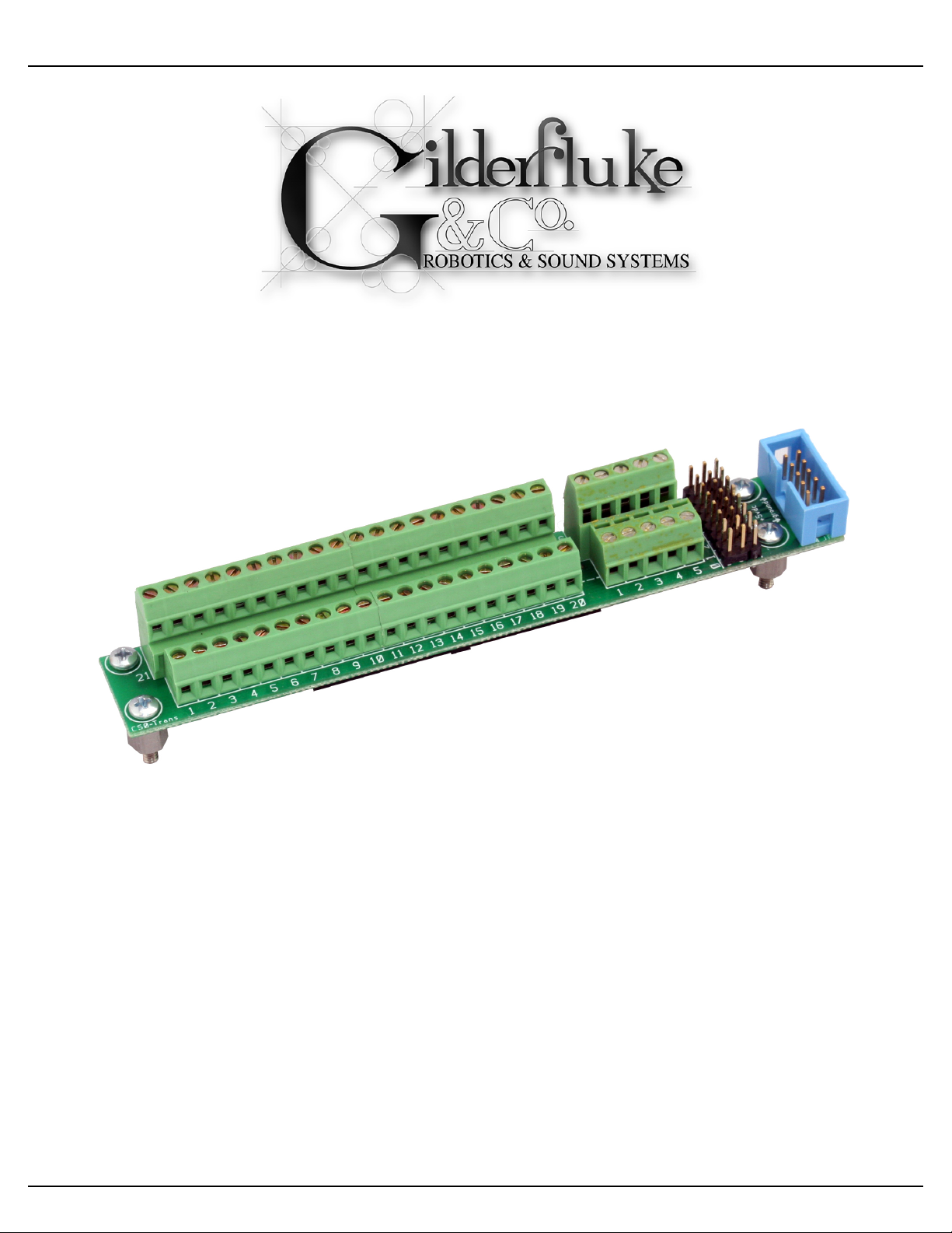
C-50Trans Transition Connector
(Sd-50/40)
The C-50Trans is a convenient way to attach discrete wires to a Sd-50/xx for the
forty digital (on/off) Show Control Outputs. It attaches right to the top of a Sd-50/40. It
also provides convenient connections for up to eight model airplane-style PWM ServoMotors.
You install a C-50Trans by:
1)! Locating the threaded mounting holes in the case top of the Sd-50/40. Position the C-
50Trans on the top of the case by plugging it into the forty position J-6 connector. It has
a polarizing ‘bump’ on one side, so it will only go in the correct way. Use a pin or other
pointy object to poke a hole through the Sd-50/40’s label at each of the four mounting
holes. Remove the C-50Trans from the Sd-50/40. Use an X-acto or other sharply
pointed knife to remove the label where it covers the threaded hole beneath. You only
need to expose the hole. No additional label material around the hole should be removed. Be careful not to damage the threads as you remove the label.
C-50Trans Manual / June 12, 2007 10:28 AM / page 1 of 2
Page 2

Gilderfluke & Co.• 205 South Flower Street • Burbank, California 91502 • 818/840–9484 • 800/776–5972 • fax 818/840–9485
East Coast/Florida Office • 7041 Grand National Drive • Suite 128d • Orlando, Fl. 32819 • 407/354–5954 • fax 407/354–5955
2)! Install the four 4–40 x ¼” tall male/female spacers into the four mounting holes in the
top of the Sd-50/40. To make them the required 5/16” tall, install two 1/32” thick washers
under each standoff before you screw it down.
3)! Plug the C-50Trans into the Sd-50/40. It has a polarizing ‘bump’ on one side, so it will
only go in the correct way.
4)! Screw the C-50Trans down using the four 4–40 x 3/16” screws.
5)! The ten position ribbon cable plugs into the ‘¼ J6’ connector on the end of the Sd-50/
40.
You can now terminate discrete wires into the C-50Trans. If you are attaching ServoMotors, just
switch the ‘¼ J6’ Internal/External Power to the ‘External’ power position. Attach your ServoMotors’
five vdc supply to screw terminals #1 (ground) and #10 (+5 vdc) of the ‘¼ J6’ screw terminal block.
Plug the servos into the headers and configure the appropriate outputs for ServoMotor PWM control.
C-50Trans Manual / June 12, 2007 10:28 AM / page 2 of 2
 Loading...