

Page 1
Gilderfluke & Co.• 205 South Flower Street • Burbank, California 91502 • 818/840-9484 • 800/776-5972 • fax 818/840-9485
Br-SDC8 & Br-SDC/09
Serial Device Controllers v4.nn
!The Br-SDC is a complete, stand-alone Serial Output
Controller. It is used whenever you need to control any
device that needs to be fed strings of RS-232 serial
data (optionally RS-422) in response to a switch clo-
sure input. It has been preprogrammed to work with
many LaserDisk and DVD players, but can be
used with any RS-232 controlled device.
The Br-SDC8 expands the single port Br-SDC/09,
by adding eight multiplexed RS-232 output ports. It also has
two dedicated input ports, one of which is RS-232, and the other is RS422, so the Br-SDC8 can double as a level converter allowing RS-422 devices to talk to
RS-232 controlled devices.
The Br-SDCs can be controlled from
any of Gilderfluke
& Co.ʼs Show
Control Systems, PLCs or
any other control systems.
Just attach
some buttons,
and you can
make your own
interactive video
kiosk.
Br-SDC Manual / December 30, 2013 9:24 AM / page 1 of 62
Page 2

Safety Disclaimer: Any electronic or mechanical sys-
tem has a potential to fail. Certain applications using
Gilderfluke & Company equipment may involve poten-
tial risks of death, personal injury, or severe property, or
environmental damage (“Critical Application”).
Gilderfluke & Company equipment is not designed, in-
tended, authorized, or warranted to be suitable in life
support applications, devices, or systems, or other
critical applications. Inclusion of Gilderfluke & Com-
pany products in such applications is understood to be
fully at the risk of the customer. In order to minimize
risks associated with the customer's applications, ade-
quate design and operating safeguards should be pro-
vided by the customer to minimize inherent or proce-
dural hazards.
Gilderfluke & Company assumes no liability for appli-
cations assistance, customer produced design, soft-
ware performance, or infringement of patents or copy-
rights. Nor does Gilderfluke & Company warrant or rep-
resent that any license, either express, or implied, is
granted under any patent right, copyright, mask work
right, or other intellectual property right of Gilderfluke &
Company covering or relating to any combination, ma-
chine, or process in which Gilderfluke & Company
products or services might be or are used.
Gilderfluke & Co.• 205 South Flower Street • Burbank, California 91502 • 818/840-9484 • 800/776-5972 • fax 818/840-9485
Br-SDC Manual / December 30, 2013 9:24 AM / page 2 of 62
Page 3

Gilderfluke & Co.• 205 South Flower Street • Burbank, California 91502 • 818/840-9484 • 800/776-5972 • fax 818/840-9485
..................................................................................Br-SDC Overview! 7
...............................Features of the Br-SDC/09, Br-SDC/422 or Br-SDC8 include:! 7
...........................................................Features exclusive to the Br-SDC8 include:! 8
........................................Br-SDC LEDs, Switches and Connections:! 9
..............................................................................................................Status LEDs:! 9
.........................................................................................ʻConfigure/Runʼ Switch:! 10
.............................................................................................................Serial Ports:! 10
.............................................................................................................1/4-J6 Input:! 12
.........................................................................................................ʻ8ʼ & ʻ9ʼ Inputs:! 13
.........................................................................................................Power Supply:! 13
........................................................Br-SDC Software Configuration! 15
................................................................................Entering Configuration Mode:! 16
..................................................................Br-SDC Input Setup Menu! 19
...................................................................................LaserDisk/DVD Player type:! 22
...............................................................................................................Baud Rate:! 22
.................................................................................Clear Configuration Memory:! 23
................................................................................................Save Configuration:! 24
.............................................................................................................Edit Strings:! 25
..............................................................................................................Frame Rate:! 26
........................................................................................................................Mode:! 26
..................................................................................................Edit Input Actions:! 30
..............................................................ʻStringʼ that will be sent on this closure:! 30
................................................................................................Delay Timer Length:! 30
...................................................................................LaserDisk/DVD Start frame:! 31
....................................................................................LaserDisk/DVD End Frame:! 31
...................................................................................String/Show to play at End:! 32
.............................................................................String/Show to play on Failure:! 32
........................................................................................................................Kopy:! 32
...........................................................................Br-SDC String Menu! 33
...................................................................................LaserDisk/DVD Player type:! 35
...............................................................................................................Baud Rate:! 36
.................................................................................Clear Configuration Memory:! 36
................................................................................................Save Configuration:! 37
.............................................................................................................Edit Strings:! 39
..............................................................................................................Frame Rate:! 39
........................................................................................................................Mode:! 39
............................................................................................................Edit String n:! 44
...........................................................................................................Edit Entry nn:! 45
..................................................................................................................Tx Value:! 45
..................................................................................................................Rx Value:! 45
........................................................................................................................Kopy:! 45
.....................................................................................................................Tx Text:! 45
....................................................................................................................Rx Text:! 46
.....................................................LaserDisc/DVD Search (displayed as ʻserchʼ):! 46
........................................................LaserDisk/DVD End (displayed as ʻLdEndʼ):! 47
Br-SDC Manual / December 30, 2013 9:24 AM / page 3 of 62
Page 4

Gilderfluke & Co.• 205 South Flower Street • Burbank, California 91502 • 818/840-9484 • 800/776-5972 • fax 818/840-9485
.........................................................................Start Timer (displayed as ʻtimerʼ):! 47
......................................................................Rx Anything (displayed as ʻ__?__ʼ):! 47
....................................................................End Of String (displayed as ʻ_end_ʼ):! 47
......................................................Eight Bit Binary value (displayed as ʻ_BIN_ʼ):! 47
...............................................Two character HEX value (displayed as ʻ_HEX_ʼ):! 47
...........................................Three character BCD value (displayed as ʻ_BCD_ʼ):! 48
........................................................................Transmit to ALL, Receive from #1:! 48
...........................................................................Transmit to #1, Receive from #1:! 48
...........................................................................Transmit to #2, Receive from #2:! 48
...........................................................................Transmit to #3, Receive from #3:! 48
...........................................................................Transmit to #4, Receive from #4:! 48
...........................................................................Transmit to #5, Receive from #5:! 48
...........................................................................Transmit to #6, Receive from #6:! 48
...........................................................................Transmit to #7, Receive from #7:! 48
...........................................................................Transmit to #8, Receive from #8:! 48
.................................................Pioneer LaserDisk/DVD Commands! 51
..............................................................Sony LaserDisk Commands! 57
...........................................HEXadecimal to Decimal to Percentage! 62
Br-SDC Manual / December 30, 2013 9:24 AM / page 4 of 62
Page 5

Gilderfluke & Co.• 205 South Flower Street • Burbank, California 91502 • 818/840-9484 • 800/776-5972 • fax 818/840-9485
this is a blank page
Br-SDC Manual / December 30, 2013 9:24 AM / page 5 of 62
Page 6
Gilderfluke & Co.• 205 South Flower Street • Burbank, California 91502 • 818/840-9484 • 800/776-5972 • fax 818/840-9485
A note about this manual:
This manual covers the specifics of the Br-
SDC. To configure the Br-SDC you will need a
simple serial terminal program. We provide one
called GilderTerm for free with our software.
GilderTerm can be downloaded from our web
site at:
http://www.gilderfluke.com
Br-SDC Manual / December 30, 2013 9:24 AM / page 6 of 62
Page 7

Gilderfluke & Co.• 205 South Flower Street • Burbank, California 91502 • 818/840-9484 • 800/776-5972 • fax 818/840-9485
Br-SDC Overview
The Br-SDCs are configured using the RS-232 serial port of any PC compatible
computer. The only software you need on your PC is a simple ʻterminalʼ program. Typical of these is HyperTerm. We recommend GilderTerm, which is available free from
Gilderfluke & Co..
Once a configuration is completed, serial strings are sent from the Br-SDC through
its standard RS-232 serial port to whatever it is controlling. Typically, the Br-SDC is attached right on the back of the controlled device.
Features of the Br-SDC/09, Br-SDC/422 or Br-SDC8 include:
Fifteen different serial strings of up to 127 characters each.
•
Unplug it from the device it normally controls and plug it into the serial port on
•
a PC to configure.
ʻWrite Protectʼ switch protects against accidental configuration changes. Con-
•
figurations should last about forty years.
Ten optoisolated inputs to synchronize Br-SDCs with pushbuttons, real-time
•
events and other control systems. Two of the inputs use screw terminals. The
other eight use a standard 1/4-J6 connector.
Different actions can take place on the opening and closing edges of any in-
•
put.
The Br-SDC can send a different string, or play a different show when it has
•
completed any string.
Strings can include ʻdelaysʼ of one frame to over nine hours.
•
It can send a different string, or play a different show if any string gets an in-
•
correct serial response from the device it is controlling.
Built in software to control Pioneer LaserDisk and DVD players, or Sony
•
LaserDisk players.
Supports both CAV (thirty minute) and CLV (one hour) LaserDisks.
•
Available with DE-09 female or DB-15 male (for Pioneer LaserDisks and
•
DVDs).
The Br-SDC runs on anything from 9-24 VDC. It includes a small 9 VDC
•
'wallwart' power supply. It can even be run from batteries.
Br-SDCs are often mounted by their connectors or by Velcro on their backs.
•
Br-SDC Manual / December 30, 2013 9:24 AM / page 7 of 62
Page 8

Gilderfluke & Co.• 205 South Flower Street • Burbank, California 91502 • 818/840-9484 • 800/776-5972 • fax 818/840-9485
Typically mounted right on whatever it is controlling.
Features exclusive to the Br-SDC8 include:
Adds eight downstream RS-232 serial ports for controlling multiple devices.
•
ʻConfig./Mux. RS-232 portʼ (female DE-09) or ʻMux./RS-422ʼ (female Rj-12)
•
upstream ports.
Strings can be sent to one or more of the serial outputs simultaneously.
•
Responses to serial strings can be received from the controlled devices one
•
at a time.
Can be used as a multiplexer to route serial data to and from a single serial
•
data source to one or more outputs simultaneously. Which serial outputs are
selected can be done using simple ʻAT+++ʼ commands as part of the strings
you send it, or using the switch closure inputs.
Br-SDC Manual / December 30, 2013 9:24 AM / page 8 of 62
Page 9

Gilderfluke & Co.• 205 South Flower Street • Burbank, California 91502 • 818/840-9484 • 800/776-5972 • fax 818/840-9485
Br-SDC LEDs, Switches and Connections:
There are only a small number of LEDs, connections and single configuration switch
on each Br-SDC.
Status LEDs:
On the Br-SDC/09, Br-SDC/422:
1) Green ʻHeartʼ LED. This is used so you can see that the Br-SDC is alive. If this
LED doesnʼt flash at least once per second, you should power down the Br-SDC
and check the power supply and connections to the Br-SDC. When in configuration mode, the Br-SDCʼs ʻheartʼ LED will flash at a far faster rate than normal.
2) Red LED attached to the serial data input line on the Br-SDC. Any time the Br-
SDC receives something through its serial port, you will see this LED flash.
3) Yellow LED attached to the serial data transmission line on the Br-SDC. Any time
the Br-SDC sends out something through its serial port, you will see this LED
flash.
On the Br-SDC8:
1) Yellow ʻHeartʼ LED. This is used so you can see that the Br-SDC8 is alive. If this
LED doesnʼt flash at least once per second, you should power down the Br-SDC8
and check the power supply and connections to the Br-SDC.When in configuration mode, the Br-SDCʼs ʻheartʼ LED will flash at a far faster than the normal
ʻRunningʼ rate.
2) Green LED attached to the serial data input on the Br-SDC8ʼs ʻConfig./Mux. RS-
232 portʼ (female DE-09) or ʻMux./RS-422ʼ (female Rj-12) ports. Any time the Br-
SDC8 receives something through this serial port, you will see this LED flash. You
will see this during configuration, or when operating in any of the multiplexer
modes.
3) Red LED attached to the serial data output on the Br-SDC8ʼs ʻConfig./Mux. RS232 portʼ (female DE-09) or ʻMux./RS-422ʼ (female Rj-12) ports. Any time the Br-
SDC8 sends something out through this serial port, you will see this LED flash.
You will see this during configuration, or when operating in any of the multiplexer
modes, when serial data received through one of the multiplexed serial ports 1-8
(male DE-09) is routed to the Br-SDC8ʼs ʻConfig./Mux. RS-232 portʼ (female DE-
09) or ʻMux./RS-422ʼ (female Rj-12) ports.
4) Green LED attached to the serial data output on the Br-SDC8ʼs multiplexed serial
ports 1-8 (male DE-09). Any time the Br-SDC8 sends out something through one
Br-SDC Manual / December 30, 2013 9:24 AM / page 9 of 62
Page 10

Gilderfluke & Co.• 205 South Flower Street • Burbank, California 91502 • 818/840-9484 • 800/776-5972 • fax 818/840-9485
or more of these serial ports, you will see the adjacent LED flash.
ʻConfigure/Runʼ Switch:
This switch must be in the ʻDisabledʼ position for the Br-SDC to receive and send
strings normally. When this switch is in the ʻDisabledʼ position, there is no possible way
for a Br-SDC to alter its memory and the Br-SDC operates normally, receiving charac-
ters and sending strings in response to inputs.
! With the switch in the ʻConfigureʼ position, the serial port is forced to 9600 baud,
and is put into ʻconfigurationʼ mode. The Br-SDCʼs built-in menu is displayed on a com-
puter attached to the female DE-09 serial port1 and configuration reads and writes can
take place normally.
When in configuration mode, the Br-SDCʼs ʻheartʼ LED will flash at a far faster than
the normal ʻRunningʼ rate.
! With the switch in the ʻDisabledʼ position, the Br-SDC should retain its configura-
tions for at least forty years. The serial port is returned to the baud rate selected during
setup, and the Br-SDC returns to ʻnormalʼ operation.
Serial Ports:
There are several different options available on the Br-SDCs for RS-232 or RS-422
Serial port connectors:
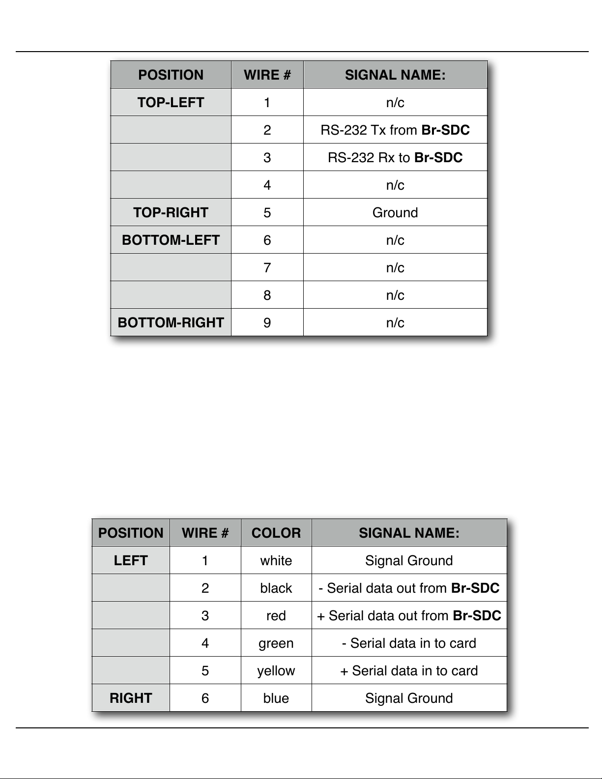
a) DE-09 Nine Position Female:
On the Br-SDC/09, this connection is used for both configuration and sending
strings to the devices the Br-SDC/09 controls. When connecting the Br-SDC/09 to
your controlled device, this may require a cable that flips pins #2 and #3.
On the eight port Br-SDC8, this female connection is used for configuration,
and for attaching the Br-SDC8 to the your PC, PLC, or other source of serial data.
The RS-232 serial port is paralleled with the RS-244 serial port. You can use either port interchangeably, but not at the same time. The eight male DE-09 connectors are used to attach the devices that receive the strings that the Br-SDC8 generates or reroutes.
A nine pin male to nine pin female serial cable with ʻstraight throughʼ wiring is
used to connect the Br-SDC to your PC or PLC. The pins that the Br-SDC uses
are:
1
The computer must be running a terminal program, such as GilderTerm, HyperTerm or others.
Br-SDC Manual / December 30, 2013 9:24 AM / page 10 of 62
Page 11
POSITION
WIRE #
SIGNAL NAME:
TOP-LEFT
TOP-RIGHT
BOTTOM-LEFT
BOTTOM-RIGHT
1
n/c
2
RS-232 Tx from Br-SDC
3
RS-232 Rx to Br-SDC
4
n/c
5
Ground
6
n/c7n/c8n/c9n/c
POSITION
WIRE #
COLOR
SIGNAL NAME:
LEFT
RIGHT
1
white
Signal Ground
2
black
- Serial data out from Br-SDC
3
red
+ Serial data out from Br-SDC
4
green
- Serial data in to card
5
yellow
+ Serial data in to card
6
blue
Signal Ground
Gilderfluke & Co.• 205 South Flower Street • Burbank, California 91502 • 818/840-9484 • 800/776-5972 • fax 818/840-9485
b) RS-422 (female Rj-12):
The single port Br-SDC/422 replaces the RS-232 port with a RS244 serial port.
On the eight port Br-SDC8, the RS-232 serial port is paralleled with the RS-244
serial port. You can use either port interchangeably, but not at the same time.
The serial data signals from the Br-SDC are brought out on a six position RJ12 (six position, six conductor modular telephone style connector) on the card
cage. Facing the end of the cable with the release latch upwards, its pin out is as
follows:
Br-SDC Manual / December 30, 2013 9:24 AM / page 11 of 62
Page 12
POSITION
WIRE #
SIGNAL NAME:
TOP-RIGHT
TOP-LEFT
BOTTOM-RIGHT
BOTTOM-LEFT
1
n/c
2
RS-232 Rx to Br-SDC8
3
RS-232 Tx from Br-SDC8
4
n/c
5
Ground
6
n/c7n/c8n/c9n/c
External Power
(Brown) PIN #1
(red) PIN #2
(orange) PIN #3
(yellow) PIN #4
(green) PIN #5
(blue) PIN #6
(violet) PIN #7
(grey) PIN #8
(white) PIN #9
(black) PIN #10
GROUND
DATA BIT 7
DATA BIT 6
DATA BIT 5
DATA BIT 4
DATA BIT 3
DATA BIT 2
DATA BIT 1
DATA BIT 0
+ 5 to 24 VDC SUPPLY
Gilderfluke & Co.• 205 South Flower Street • Burbank, California 91502 • 818/840-9484 • 800/776-5972 • fax 818/840-9485
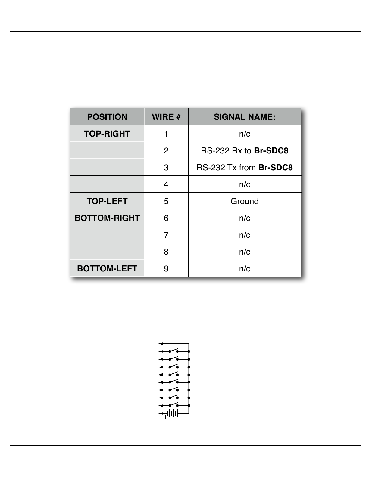
c) DE-09 Nine Position Male:
On the eight port Br-SDC8, these eight male connections are used to attach
the devices that receive the strings that the Br-SDC8 generates or reroutes.
A nine pin male to nine pin female serial cable with ʻstraight throughʼ wiring
should be used to connect the Br-SDC to your controlled devices. The pins that
the Br-SDC uses are:
1/4-J6 Input:
This connector has eight optically isolated inputs. It requires an external power
source. It is compatible with the digital outputs from any Gilderfluke & Company Show
Control Systems.
Br-SDC Manual / December 30, 2013 9:24 AM / page 12 of 62
Page 13

External Power
(+ 5-24 VDC supply)
terminal #1
terminal #2
terminal #3
terminal #4
DATA BIT 8
DATA BIT 9
Gilderfluke & Co.• 205 South Flower Street • Burbank, California 91502 • 818/840-9484 • 800/776-5972 • fax 818/840-9485
Any event can be triggered on either the ʻclosingʼ or ʻopeningʼ edge of any input. A
ʻclosingʼ is when you ground an input. An ʻopeningʼ is when that grounding is removed.
The inputs can be triggered on any voltage from 9 to 24 VDC. If you donʼt have an external source of power for these two inputs, you can ʻstealʼ some juice from the Br-
SDCʼs power supply.
ʻ8ʼ & ʻ9ʼ Inputs:
These are two optically isolated digital inputs. Unlike the 1/4-J6 inputs, these can be
wired to switch either side of the photo diode:
Versions of the Br-SDC 2.0 or later use a bipolar optoisolator on inputs 8 and 9. This
means that you can ignore the polarity markings shown in the above illustrations on all
versions of the Br-SDC 2.0 and later.
Any event can be triggered on either the ʻclosingʼ or ʻopeningʼ edge of either input. A
ʻclosingʼ is when you apply a voltage to an input. An ʻopeningʼ is when that voltage is
removed. The inputs can be triggered on any voltage from 5 to 24 VDC. If you donʼt
have an external source of power for these two inputs, you can ʻstealʼ some juice from
the Br-SDCʼs power supply.
Power Supply:
(5.5 mm O.D. / 2.1 mm I.D. power jack)
The Br-SDC can be run from any supply voltage from 9-24 VDC.
The outer ring is used for the ground, and the middle pin is used for the positive connection. This input is protected from reverse polarity connections. An idle Br-SDC draws
only about twenty-five milliamperes. It can run for days on just a single nine volt battery.
Br-SDC Manual / December 30, 2013 9:24 AM / page 13 of 62
Page 14

Gilderfluke & Co.• 205 South Flower Street • Burbank, California 91502 • 818/840-9484 • 800/776-5972 • fax 818/840-9485
this is not a blank page
Br-SDC Manual / December 30, 2013 9:24 AM / page 14 of 62
Page 15

Gilderfluke & Co.• 205 South Flower Street • Burbank, California 91502 • 818/840-9484 • 800/776-5972 • fax 818/840-9485
Br-SDC Software Configuration
The Br-SDC can be accessed through the serial port from any computer running just
about any modem or terminal program. We provide a free terminal program called GilderTerm that makes working with GilderGear through the serial port a little easier. The
computer you are using doesnʼt even need to have any PC•MACs software installed on
it.
Most Gilderfluke & Co. products can be controlled through their RS-232 or RS-422
Serial ports. The Br-SDC has a single RS-232 (Br-SDC/09) or RS-422 (Br-SDC/422)
serial port on it.
An RS-232 serial port typically controls a single device with a serial RS-232 port on it.
With an RS-422 serial port, many different cards and devices can be attached to the
same RS-422 serial lines to form an RS-422 ʻmulti Dropʼ network. Commands can be
addressed to a single card on the network, or all the cards simultaneously.
If you donʼt have access to GilderTerm, typical modem programs you can use are
Terminal.exe (which came with Windows 3.1) and HyperTerm.exe (which comes with
later versions of Windows).
GilderTerm is available free from Gilderfluke & Co. for use with all of our products. It
can be downloaded from our web page, and is included on all of our CD-ROMs. GilderTerm has been optimized for use with all Gilderfluke & Company equipment. All the
commands are built in, and it will even let you use your mouse to select commands by
clicking on the menus.
If you are using GilderTerm, all the settings are fixed at the appropriate settings. All
you will need to do is select the appropriate ʻCOMʼ port. To talk to the Br-SDC, just configure your terminal program for 9600 baud, no parity, eight data bits, one stop bit and
no flow control handshaking.
Computers donʼt normally come with serial ports on them anymore. Instead, you use
a USB-to-Serial (USB-RS232/422 or C-USB-RS232) adapter, BlueTooth-to-Serial (Bt-
Rs232Rx and Bt-USBTx), Ethernet-to-Serial (Modem-Internet) adapter, or WiFi-to-Serial
(Modem-Wi-Fly) adapter. For the Br-SDC you will need one that provides the more
common RS-232. These are available from a number of different sources, including
Gilderfluke & Company. Our part number is USB-RS232/422 for the USB-to-Serial
adapter that provides both RS-232 and RS-422 connections, or the simpler RS-232-only
adapter is the C-USB-RS232.
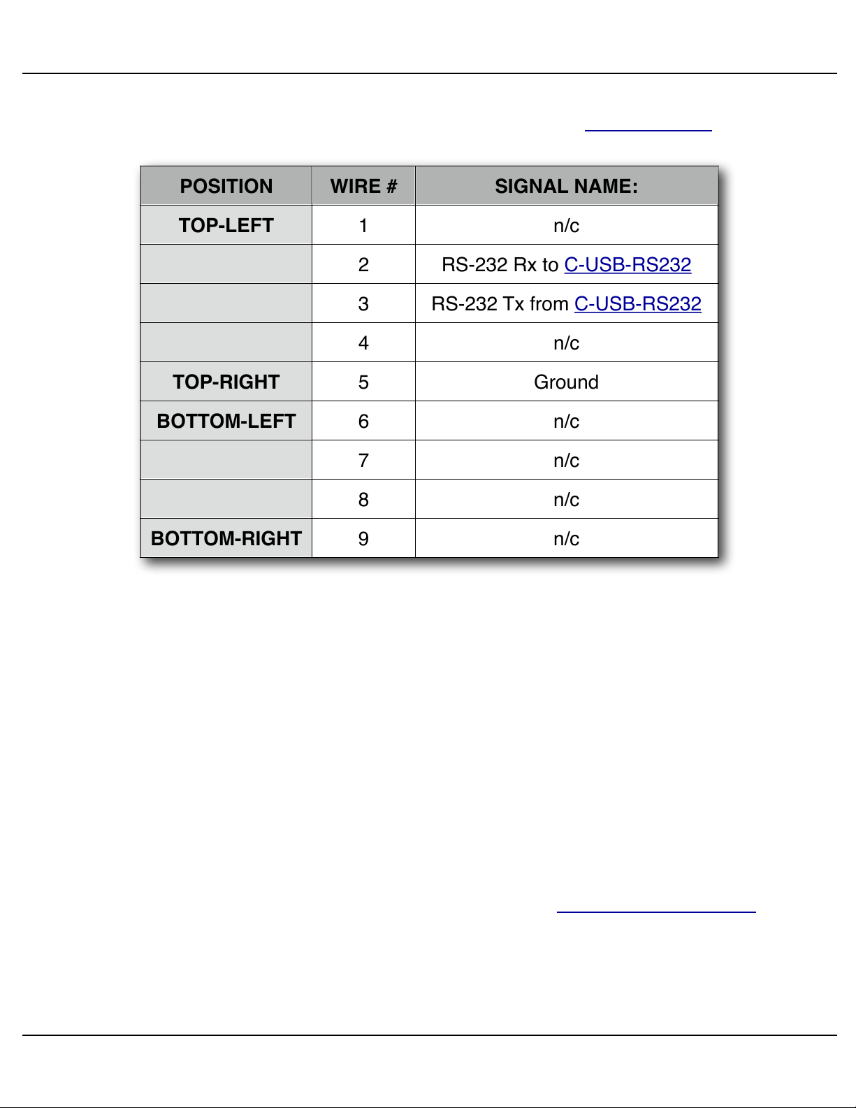
If you have hooked up the Br-SDC to your computer and it still doesn't seem to respond to the keyboard, the first thing to check is that you are attached to the right serial
port. The easiest way to do this is to disconnect the Br-SDC and short between the Tx
Br-SDC Manual / December 30, 2013 9:24 AM / page 15 of 62
Page 16
POSITION
WIRE #
SIGNAL NAME:
TOP-LEFT
TOP-RIGHT
BOTTOM-LEFT
BOTTOM-RIGHT1n/c
2
RS-232 Rx to C-USB-RS232
3
RS-232 Tx from C-USB-RS232
4
n/c
5
Ground
6
n/c7n/c8n/c9n/c
Gilderfluke & Co.• 205 South Flower Street • Burbank, California 91502 • 818/840-9484 • 800/776-5972 • fax 818/840-9485
data out and Rx data in pins on your USB-to-Serial converter. For an RS-232 port, this
means temporarily shorting pins #2 and #3 together. On the C-USB-RS232, the pinout
is as follows:
While still running the modem program, anything you type should be shown on the
screen while these jumpers are in place, while nothing will appear when you remove
them. If your computer passes this test, then you are using the right serial port and the
problem is most likely the baud rate setting or in your wiring to the Br-SDC. If you get
characters on the screen even with the jumpers removed from the serial port, it means:
a) You need to set the 'echo' mode to 'none' or 'full duplex' and try this test again,
or…
b) You are talking to a different serial port than the one you actually want.
3) String Setup: This screen is used to set up which characters are sent and received in each string.
Entering Configuration Mode:
To enter the configuration mode you need to move the ʻConfigure/Runʼ Switch to the
ʻconfigureʼ position. The ʻheartʼ LED will begin flashing at about four times per second,
instead of the usual twice per second. The Br-SDC will then send out its menu through
the main serial port. If you have a computer attached and running a terminal program
Br-SDC Manual / December 30, 2013 9:24 AM / page 16 of 62
Page 17

Gilderfluke & Co.• 205 South Flower Street • Burbank, California 91502 • 818/840-9484 • 800/776-5972 • fax 818/840-9485
set to the default 9600 baud, N, 8, 1, you will see the menu displayed on your computerʼs screen. There are two configuration screens in the Br-SDC:
1) Trigger Setup Screen: On this screen, you set which input sends out which string.
2) String Setup: This screen is used to set up which characters are sent and received in each string.
To redraw any screen at any time, just press the <ESC>ape key or <SPACE> bar.
All numeric values are entered in Decimal (0-9) or HEXadecimal (0-9, A-F) numbers.
Each number consist of one or more ASCII characters followed by a <RETURN> (<ENTER> on some keyboards). If more characters have been entered before the <RETURN> than are allowed, then the characters already entered will scroll to the left to
make room for the new entries. Once a command has been invoked, characters can be
erased one-by-one by using the <DELETE> key (<BACKSPACE> on some keyboards).
An entire entry can be erased by hitting the <ESC>ape key. A command can be canceled altogether by hitting the <RETURN> key (<ENTER> on some keyboards) or
<ESC>ape key after all the characters have been erased or before any have been entered.
Once you have configured a Br-SDC, you can ʻlockʼ the configuration by moving the
ʻConfigure/Runʼ Switch to the ʻrunʼ position. This should protect your configuration from
anything short of a lightning hit. The ʻHeartʼ LED will slow to the normal running rate,
and you can test your strings by triggering them through the 0-9 switch closure inputs.
Configuration changes can be re-enabled at any time by moving the switch back to the
ʻConfigureʼ position.
If you want to keep a hard copy printout of the current configuration of the Br-SDC,
you should use the <ESC>ape key to redraw the screen while ʻsaving to fileʼ in the modem program running on your computer. This file can be printed out at any time, or
spliced into the documentation package for your project.
Br-SDC Manual / December 30, 2013 9:24 AM / page 17 of 62
Page 18

Gilderfluke & Co.• 205 South Flower Street • Burbank, California 91502 • 818/840-9484 • 800/776-5972 • fax 818/840-9485
this page is not blank either
Br-SDC Manual / December 30, 2013 9:24 AM / page 18 of 62
Page 19
- Gilderfluke & Co. - Br-SDC Serial Device Controller - ver. 2.13 (c) 2014 DCM -
a) Pioneer CAV, b) 9600 baud, c) clear, d) save, e) string, f) 30 FPS, 9) mode
Input 2 close:1) string, 2) delay, 3) dvd start/end, 4) @end, 5) @fail, 6) kopy
g) 0 c:
h) 0 O:
i) 1 c:
j) 1 O:
K) 2 c: STRING-3 | DELAY-123,456 | DVD-123,456 / END-654,321 | @END-4 | @FAIL-5
l) 2 O:
m) 3 c:
n) 3 O:
o) 4 c:
p) 4 O:
q) 5 c:
r) 5 O:
s) 6 c:
t) 6 O:
u) 7 c:
v) 7 O:
w) 8 c:
x) 8 O:
y) 9 c:
z) 9 O:
Enter Command-
Gilderfluke & Co.• 205 South Flower Street • Burbank, California 91502 • 818/840-9484 • 800/776-5972 • fax 818/840-9485
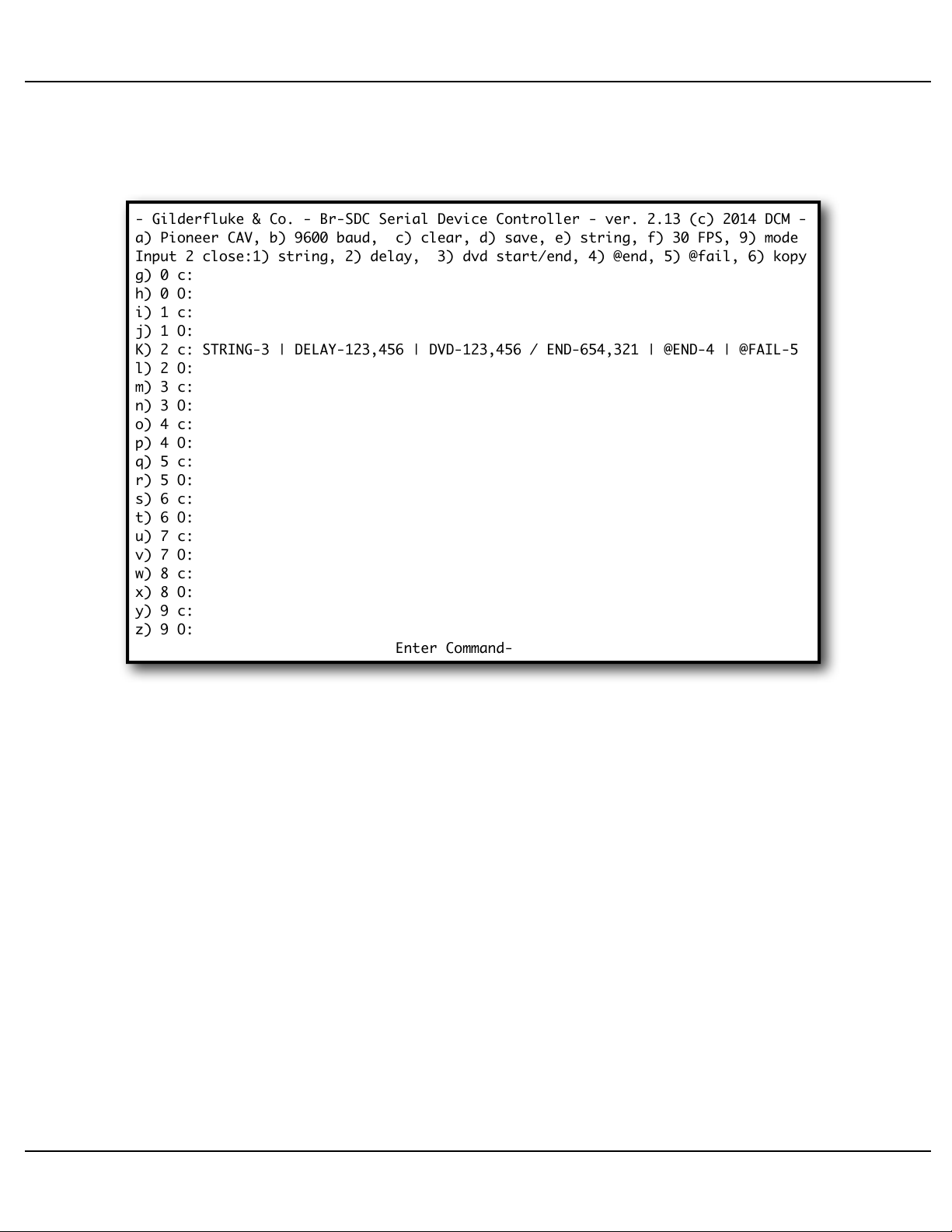
Br-SDC Input Setup Menu
The Trigger Setup menu will appear as follows (Br-SDC/09 shown):
This screen is used to set what happens on each of the ten switch closure inputs.
Different actions can be chosen for the opening or closing edge of each input. The options are:
that will take place one each of the ten optically isolated inputs. Each of these inputs
has both a ʻclosingʼ edge (shown by a ʻcʼ) and opening edge (shown by an ʻoʼ) action. If
1) Which of the fifteen possible strings (0=none, 1-F) will be sent on this input/
edge.
2) If a ʻDelayʼ marker (ʻTIMERʼ) is found in the string, how long (in 30 FPS or 25
FPS frames) the delay will be.
3) If a DVD ʻSearchʼ marker (ʻSERCHʼ) is found in the string, then what frame
number on the DVD will be searched for.
4) String to send at end of this string, if it completes successfully.
5) String to send at end of this string, if it encounters an error while sending this
string.
Several commands are shown at the top of the screen. Below this are the actions
Br-SDC Manual / December 30, 2013 9:24 AM / page 19 of 62
Page 20

Gilderfluke & Co.• 205 South Flower Street • Burbank, California 91502 • 818/840-9484 • 800/776-5972 • fax 818/840-9485
the input is currently closed, the small ʻcʼ will be printed as an upper case ʻCʼ. This allows you to see if the external connections to the Br-SDC are working properly. The
screen will not be updated until it redraws. You can force the screen to redraw by hitting
the <space bar> or <ESC>ape keys.
In most cases, strings used in the Br-SDC first search for a specific ʻLDP Startʼ frame
number on the LaserDisk/DVD. As soon as it finds this frame, the next characters in the
string tell it to start the player ʻplayingʼ. At this point, you can either start a timer or start
polling the LaserDisk/DVD for the end frame of the show. When the timer times out or
the LaserDisk/DVD end frame is found, then the next characters in the string tell the
LaserDisk/DVD to stop (or ʻstillʼ). If all of this has completed successfully, then the Br-
SDC will play whatever show/string has been set for the ʻ@endʼ. If there is a failure
anywhere in the string, then the ʻ@failʼ show/string will be played.
If you want to tell the Br-SDC to send out a string on power-up, then all you need to
do is set the action you want to happen on any unused ʻopeningʼ input. When power is
applied to the Br-SDC, it will see that this input has ʻjust openedʼ, and send the string
you have requested.
To loop a single string, all you need to do is tell any show to use the same string as it
does when it starts as the string to play ʻ@endʼ. It will then play this same string over
again each time it finishes. If you have an initialization that needs to be done to a serial
device before the first loop of the day, you can use a string that initializes the device as
the ʻnormalʼ triggered string, and then use the string that ʻplaysʼ the serial device as the
string ʻ@endʼ. It will play the ʻnormalʼ string once, and then loop the ʻ@endʼ string for the
rest of the day.
If you are synchronizing multiple LaserDisk/DVD players, you will probably want to
use a single input (wired in parallel on all of the Br-SDCs) to tell all of the LaserDisk/
DVD players to their respective start frames. A second input, wired in parallel to all of
the Br-SDCs, then is used to simultaneously tell all of the players to start ʻplayingʼ. You
can then either start a timer or start polling the LaserDisk/DVD for the end frame of the
show. When the timer times out or the LaserDisk/DVD end frame is found, then the next
characters in the frame tell the LaserDisk/DVD to stop (or ʻstillʼ).
If the Br-SDC has been set for binary mode, then the screen will appear as follows:
Br-SDC Manual / December 30, 2013 9:24 AM / page 20 of 62
Page 21

- Gilderfluke & Co. - Br-SDC Serial Device Controller - ver. 2.13 (c) 2014 DCM -
a) Pioneer CAV, b) 9600 baud, c) clear, d) save, e) string, f) 30 FPS, 9) mode
Input 0 close:1) string, 2) delay, 3) dvd start/end, 4) @end, 5) @fail, 6) kopy
G) 0 c: STRING-3 | DELAY-123,456 | DVD-123,456 / END-654,321 | @END-4 | @FAIL-5
h) 0 O:
Binary mode: 00000000b / 00h / __0
w) 8 c:
x) 8 O:
y) 9 c:
z) 9 O:
Enter Command-
Gilderfluke & Co.• 205 South Flower Street • Burbank, California 91502 • 818/840-9484 • 800/776-5972 • fax 818/840-9485
The inputs for individual inputs 1 though 7 have disappeared from the screen. Any 1/
4-J6 input change that does not equal zero is considered to be a ʻclosingʼ action, and
the string set for ʻbit 0 closingʼ, will take place. Any change in the 1/-J6 inputs which results in a ʻzeroʼ value will be treated as an ʻopeningʼ edge, and the actions set for ʻbit 0
closingʼ, will take place. The current status of the 1/4-J6 input is displayed one the menu
each time the screen is redrawn.
When a Br-SDC8 is in mode0, the entire string menu and all but four commands on
the Input Setup menu are disabled, and the trigger menu is drawn with instructions for
the multiplexer mode:
Br-SDC Manual / December 30, 2013 9:24 AM / page 21 of 62
Page 22

- Gilderfluke & Co. - Br-SDC8 Multiport Serial Controller - v2.11 (c) 2014 DCM -
b) 9600 baud, c) clear to default, d) save configuration thru serial, 9) mode 0
Serial Multiplexer (Mode 0) selected:
no strings or shows are available
use J6 bits 0, 1, 2 and 3 of J6 or AT+++ commands to select multiplexer channels
00000000b / 00h / __0
Enter Command-
Gilderfluke & Co.• 205 South Flower Street • Burbank, California 91502 • 818/840-9484 • 800/776-5972 • fax 818/840-9485
a) LaserDisk/DVD Player type:
This command is used to select which type of LaserDisk/DVD is going to be used
with the Br-SDC. Supported types are Pioneer or Sony. For each of these, you can also
select whether it will be using a standard CAV (thirty minutes maximum length) disk, or
an extended CLV (60 minutes maximum length) disk. DVDs all use frame references,
and numbers from 1 to 9,999,999 are valid (assuming there are that many frames recorded on your disk!).
CAV disks use frame number references between one and 54,000 frames. CLV disks
use time references between 0:00:00.01 and 9:59:59.29. The display on this screen will
be modified to show the appropriate numbering system for the LaserDisk/DVD selected.
You can switch back and forth between CAV and CLV disk formats to review the
frame numbers you have entered either in ʻframesʼ or ʻtimeʼ formats.
If using a Pioneer DVD-V7200, DVD-V7400 (or their PAL equivalents DVD-V7100 or
DVD-V7300), you should set the Br-SDC for ʻPioneer CAVʼ mode.
b) Baud Rate:
This command toggles among the eight supported baud rates:
1) 1200 baud
Br-SDC Manual / December 30, 2013 9:24 AM / page 22 of 62
Page 23

Gilderfluke & Co.• 205 South Flower Street • Burbank, California 91502 • 818/840-9484 • 800/776-5972 • fax 818/840-9485
2) 2400 baud
3) 4800 baud
4) 9600 baud (default)
5) 19,200 baud
6) 38,400 baud
7) 57,600 baud
8) 115,200 baud
No matter the baud rate chosen, configuration will always take place at 9600 baud.
The Br-SDC will only switch to another baud rate upon exiting configuration.
c) Clear Configuration Memory:
This command is used to reload the default configurations into the Br-SDC. Default
configuration loads a sequence into bit 0 closing edge that will access frame 1000 of a
Pioneer CAV LaserDisk/DVD player, play until frame 2000, delay for 500 frames, and
then repeat.
Six default strings are loaded in the Br-SDC. These are the most commonly used
strings. They can be used as-is, modified, or deleted altogether, depending on your application:
1) For Pioneer LaserDisk and DVD players. This string is used to loop a single video
sequence, with a delay between each iteration of the loop. It tells a Pioneer
LaserDisk/DVD player to:
a)! Search for a frame number.
b)! Start the Player playing once it is found.
c)! Search for an ending frame number.
c)! Stop when it is found.
d)! Delay for the amount of time entered in the ʻshow lengthʼ.
Note that because of the length of this string, it will not show in its entirety on an
eighty column wide display. You will need to scroll the screen to the right or use a screen
setting that is wider than eighty columns.
2) For Pioneer LaserDisk and DVD players. This string will tell a Pioneer LaserDisk/
DVD player to:
a) Search for a frame number.
b) Start the Player playing once it is found.
c) Search for an ending frame number.
3) For Pioneer LaserDisk and DVD players. This string will tell a Pioneer LaserDisk/
DVD player go to:
Br-SDC Manual / December 30, 2013 9:24 AM / page 23 of 62
Page 24

Gilderfluke & Co.• 205 South Flower Street • Burbank, California 91502 • 818/840-9484 • 800/776-5972 • fax 818/840-9485
a) Go to still mode.
4) For Sony LaserDisk players. This string is used to loop a single video sequence,
with a delay between each iteration of the loop. This string will tell a Sony
LaserDisk player to:
a) Search for a frame number.
b) Start the Player playing once it is found.
c) Search for an ending frame number.
d) Stop when it is found.
e) Delay for the amount of time entered in the ʻshow lengthʼ.
5) For Sony LaserDisk players. This string will tell a Sony LaserDisk player to:
a) Search for a frame number.
b) Start the Player playing once it is found.
c) Search for an ending frame number.
6) For Sony LaserDisk players. This string will tell a Sony LaserDisk player go to:
a) Go to still mode.
d) Save Configuration:
This command allows you to save a Br-SDC to the disk of your PC for archival pur-
poses, or to copy it into another Br-SDC. To use this command:
1) Press the ʻdʼ key. This will bring up an explanation of what you need to do:
Br-SDC Manual / December 30, 2013 9:24 AM / page 24 of 62
Page 25

- Gilderfluke & Co. - Br-SDC Serial Device Controller - ver. 2.13 (c) 2014 DCM -
Set your computer to save a stream of text to a file. The file should be 4095
bytes long. To reload this card, just send this file back to this screen.
Hit any key when ready.
Stop saving text and hit any key when the data has finished.
hit <ESC>ape key to cancel-
Gilderfluke & Co.• 205 South Flower Street • Burbank, California 91502 • 818/840-9484 • 800/776-5972 • fax 818/840-9485
2) Set your modem program to receive a string of text. Give the file a name of your
choosing. Hit ʻstartʼ to begin saving text.
3) Hit any key to start the download.
4) When the download has completed, the Br-SDC will give an extra line feed and
stop sending any more data.
5) Stop your computer from saving any more text.
6) Hit any key to redraw the Br-SDC menu.
To send a configuration file to a Br-SDC, all you need to do is ʻSend a Text fileʼ from
your modem program. Select a previously saved configuration and the Br-SDC will do
the rest. After the configuration has been sent, the Br-SDC will check to see if the data
arrived OK.
e) Edit Strings:
This toggles you between the menu where serial strings are edited, and the menu
where the trigger inputsʼ actions are configured.
Br-SDC Manual / December 30, 2013 9:24 AM / page 25 of 62
Page 26

Gilderfluke & Co.• 205 South Flower Street • Burbank, California 91502 • 818/840-9484 • 800/776-5972 • fax 818/840-9485
f) Frame Rate:
The standard frame rate is always thirty Frames Per Second in the parts of the world
that use NTSC video standards. In places where PAL video standards prevail, the standard frame rate is twenty-five Frames Per Second. This command allows you to select
which frame rate will be used by the Br-SDC.
Since delay times, LaserDisk and DVD player commands are all based on the frame
rate, changing this setting will affect all of these. A delay of 500 frames is 16.6 seconds
at thirty FPS. It changes to 20 seconds if the frame tare is lowered to twenty-five FPS.
9) Mode:
The 1/4-J6 input on a Br-SDC/09 or Br-SDC/422 can be switched between two
modes of operation. In the first of these, each of the eight inputs on the 1/4-J6 are used
individually to trigger strings on either the opening or closing edges of each input. In the
ʻBinaryʼ mode, the eight inputs are grouped together to form a binary value, which can
then be sent as part of a serial string. Any 1/4-J6 input change that does not equal zero
is considered to be a ʻclosingʼ action, and the string set for ʻbit 0 closingʼ, will take place.
Any change in the 1/4-J6 inputs which results in a ʻzeroʼ value will be treated as an
ʻopeningʼ edge, and the actions set for ʻbit 0 closingʼ, will take place.
When set for ʻBinaryʼ mode, a binary coded keypad (like the KP-200) can be attached to the 1/4-J6 input. A string set to be sent on the bit 0 closing edge will have the
binary value of the 1/4-J6 input inserted into it. This can be set to send a ʻshow requestʼ
and ʻplayʼ command to a Sd-50, Br-Brain4, Sd-25, Sd-10, Br-miniBrick8 or other controller.
On the Br-SDC8s, there are five modes of operation available, instead of the two on
the Br-SDC/09 or Br-SDC/422. The number of the mode is displayed on the menu next
to the ʻmodeʼ command:
1) Mode 0: This is the ʻmultiplexerʼ mode. Instead of sending strings in response to
the inputs, it simply routes the serial to/from on the Br-SDC8ʼs ʻConfig./Mux. RS232 portʼ (female DE-09) or ʻMux./RS-422ʼ (female Rj-12) ports to one or more of
the eight multiplexed male DE-09 plugs.
When a Br-SDC8 is in mode0, the string menu is disabled, and the trigger
menu is drawn with all but four commands disabled, with instructions for the multiplexer mode displayed:
Br-SDC Manual / December 30, 2013 9:24 AM / page 26 of 62
Page 27

String
Sent
Multiplexer
Selected
AT+++0 <CR>
AT+++1 <CR>
AT+++2 <CR>
AT+++3 <CR>
AT+++4 <CR>
AT+++5 <CR>
Tx = ALL, Rx = #1
Tx = #1, Rx = #1
Tx = #2, Rx = #2
Tx = #3, Rx = #3
Tx = #4, Rx = #4
Tx = #5, Rx = #5
- Gilderfluke & Co. - Br-SDC8 Multiport Serial Controller - v2.11 (c) 2014 DCM -
b) 9600 baud, c) clear to default, d) save configuration thru serial, 9) mode 0
Serial Multiplexer (Mode 0) selected:
no strings or shows are available
use J6 bits 0, 1, 2 and 3 of J6 or AT+++ commands to select multiplexer channels
00000000b / 00h / __0
Enter Command-
Gilderfluke & Co.• 205 South Flower Street • Burbank, California 91502 • 818/840-9484 • 800/776-5972 • fax 818/840-9485
Which ports are used are selected in one of two ways:
1) ATT+++ commands: Nine ʻspecialʼ strings will be intercepted by the Br-SDC8,
and not passed through to the outputs. When it receives one of these special
strings, instead of passing the string through to the currently selected male DE09 plug(s), the Br-SDC8 will use it to select a different port for sending and receiving serial data.
Br-SDC Manual / December 30, 2013 9:24 AM / page 27 of 62
Page 28

String
Sent
Multiplexer
Selected
AT+++6 <CR>
AT+++7 <CR>
AT+++8 <CR>
Tx = #6, Rx = #6
Tx = #7, Rx = #7
Tx = #8, Rx = #8
Binary
Number
Bit3
Pin #6
(+8)
Bit2
Pin #7
(+4)
Bit1
Pin #8
(+2)
Bit0
Pin #9
(+1)
Multiplexer
Selected
012345678
Off
Off
Off
Off
Tx = ALL, Rx = #1
Off
Off
Off
On
Tx = #1, Rx = #1
Off
OffOnOff
Tx = #2, Rx = #2
Off
OffOnOn
Tx = #3, Rx = #3
OffOnOff
Off
Tx = #4, Rx = #4
OffOnOff
On
Tx = #5, Rx = #5
OffOnOn
Off
Tx = #6, Rx = #6
OffOnOn
On
Tx = #7, Rx = #7
On
Off
Off
Off
Tx = #8, Rx = #8
Gilderfluke & Co.• 205 South Flower Street • Burbank, California 91502 • 818/840-9484 • 800/776-5972 • fax 818/840-9485
If more numbers (1-8) are received before the <CR> (0x0D), then you can
choose to route data to more than one of the multiplexed ports a the same time.
The first valid number between 1 and 8 sets the port that will be used of receiving
serial data and routing to the Br-SDC8ʼs ʻConfig./Mux. RS-232 portʼ (female DE-
09) or ʻMux./RS-422ʼ (female Rj-12) ports.
As an example, to send serial data out ports 3, 5, and 7, and listen to port 5 for
any serial data which is returned, you would send the string: ʻAT+++537 <CR>ʼ
2) ¼-J6 input bits 0, 1, 2 and 3: A binary pattern of bits presented on these four
input pins will select which multiplexer output is to be used:
This mode is often used with a PLC or other controller, where GPIOs are available for making the binary selections.
Br-SDC Manual / December 30, 2013 9:24 AM / page 28 of 62
Page 29

- Gilderfluke & Co. - Br-SDC8 Multiport Serial Controller - v2.13 (c) 2014 DCM -
a) Pioneer CAV, b) 9600 baud, c) clear, d) save, e) shows, f) 30 FPS, 9) mode2
h) edit string 1, i) edit entry __1, s) value to Send, g) value to Get, k) kopy
j) Tx Text, q) Rx text, l) dvd search, m) dvd End, T) start Timer, x) string end
0) Rx from one and Tx to all, 1-8) Select serial port for both Rx and Tx
|__1__|__2__|__3__|__4__|__5__|__6__|__7__|__8__|__9__|__10_|__11_|__12_
STRING1 |_MX0_|SERCH|_00H_|_'T'_|_52H_|('R')|(00H)|LDEND|_'R'_|_00H_|_F3H_|(12H)
string2 |_mx0_|serch|_0Dh_|_'u'_|_1Ah_|(16h)|(0Dh)|LdEnd|_end_|
string3 |_mx0_|_0Dh_|_0Dh_|_83h_|(02h)|(D0h)|_end_|
string4 |
string5 |
string6 |
string7 |
string8 |
string9 |
stringA |
stringB |
stringC |
stringD |
stringE |
stringF |
Enter Command-
Gilderfluke & Co.• 205 South Flower Street • Burbank, California 91502 • 818/840-9484 • 800/776-5972 • fax 818/840-9485
Note that when using the binary inputs, it is not possible to transmit through
more than one multiplexer output at one time, unless you want to transmit to all of
them simultaneously.
You donʼt want to switch between multiplexers in the middle of a message.
Make sure that the last serial message has completed transmission before you
change the selected multiplexer.
2) Mode 1: This mode of operation is combination of mode 0 and mode 2. Strings
can be triggered by the optically isolated inputs as with mode 2, but the multiplexed serial ports to sue for the strings can be selected either using the ʻAT+++ʼ
commands of mode 0, or the commands embedded in the strings that are to sent
from the internal memory of the Br-SDC8. The Br-SDC8 does not hear any of the
data returned through the multiplexed serial ports, as these are passed through to
the Br-SDC8ʼs ʻConfig./Mux. RS-232 portʼ (female DE-09) or ʻMux./RS-422ʼ (fe-
male Rj-12) ports. As with mode 2, mode 1 has the option of a ʻbinary modeʼ as
described above for the Br-SDC/09 and Br-SDC/422.
3) Mode 2: This mode is the closest in operation to the single port Br-SDC/09 and
Br-SDC/422 as described above. The only addition to the menus you will see is
the addition of the commands to select the multiplexed serial port on the string
menu:
Br-SDC Manual / December 30, 2013 9:24 AM / page 29 of 62
Page 30

Gilderfluke & Co.• 205 South Flower Street • Burbank, California 91502 • 818/840-9484 • 800/776-5972 • fax 818/840-9485
As with mode 2, mode 1 has the option of a ʻbinary modeʼ as described above for the
Br-SDC/09 and Br-SDC/422.
g) through z)
Edit Input Actions:
These commands are used to select and modify the twenty ʻshowsʼ that play when
the level of an input changes. When you have selected an input/edge, this line will be
displayed in UPPER CASE to make it easier to see. You can set:
1) ʻStringʼ that will be sent on this closure:
A string can be up to one hundred characters long, and can include commands
to:
a) Search for a specific frame on many LaserDisk/DVD players when a ʻserchʼ
marker is found in the string being sent.
b) Delay until a specific frame of a LaserDisk/DVD player has been played
when a ʻLdEndʼ marker is found in the string which is being sent.
c) Delay until a certain amount of time has passed when a ʻdelayʼ marker is
found in the string being sent.
d) Get a specific character, or any character through the serial port. These can
be entered as either HEXadecimal or ASCII text characters.
Valid string numbers are 1 through 9, A through F. A entry of ʻ0ʼ tells the Br-
SDC to not send any string on this input/edge. This disables this entire input/edge,
and the settings for that input/edge will no longer be displayed on the menu until it
is changed to a non-zero value.
2) Delay Timer Length:
This is the length that the internal timer will run for when a ʻStart Timerʼ (ʻdelayʼ)
command is found in the string that is being sent. The string will be paused until
this amount of time (in frames) has passed. The string will then continue with the
next character in the string.
Valid range of inputs for this timer are one frame to 99,999 frames. This translate into a potential time delay of over nine hours.
Br-SDC Manual / December 30, 2013 9:24 AM / page 30 of 62
Page 31

Gilderfluke & Co.• 205 South Flower Street • Burbank, California 91502 • 818/840-9484 • 800/776-5972 • fax 818/840-9485
3) LaserDisk/DVD Start frame:
This is the frame number that the Br-SDC will search for when a special ʻLaserSearchʼ (ʻserchʼ) command is found in the string that is being sent. The string
will be paused until the LaserDisk/DVD has completed the search command. The
string will then continue with the next character in the string. The ʻserchʼ command
will typically be followed by the commands to tell the LaserDisk/DVD to begin playing.
On CAV LaserDisks, the range of valid frame numbers is one to 54,000. Values
of zero will be ignored. Larger values will just confuse the LaserDisk/DVD player.
On CLV LaserDisks, the range of valid frame numbers is 0:00:00.01 to
0:59:59:29 (1 to 108,000 frames). LaserDisks are pressed with an ʻhourʼ programmed into them, typically hour ʻ0ʼ or hour ʻ1ʼ. You will need to add a value
equal to one hour worth of frames if your disk was encoded to use hour ʻ1ʼ 2.
Frame values of zero are also not allowed, and will not be sent.
LaserDisk/DVD End Frame:!
This is the frame number that the Br-SDC will poll the LaserDisk/DVD player
for when it encounters a ʻLaserDisk Endʼ (ʻLdEndʼ) command in the string being
sent. The string will be paused until the LaserDisk/DVD has passed this frame.
The string will then continue with the next entry.
DVD players respond slowly to any request for frame numbers. The Br-SDC
has code which specifically delays re-polling a LaserDisk/DVD player until it has
finished getting the last frameʼs frame number.
If the Br-SDC does not hear from the LaserDisk/DVD Player for a full second, it
will try resending the query command.
On CAV LaserDisks, the range of valid frame numbers is one to 54,000. Frame
values of zero will never be found. Larger values will just confuse the LaserDisk/
DVD player.
On CLV LaserDisks, the range of valid frame numbers is 0:00:00.01 to
0:59:59:29 (one to 108,000 frames). The Br-SDC ignores the ʻhourʼ when searching for the end of a show. Frame values of zero will never be found. Larger values
will just confuse things.
2
! 108,000 if operating at thirty FPS, 90,000 if operating at twenty-five FPS.
Br-SDC Manual / December 30, 2013 9:24 AM / page 31 of 62
Page 32

Gilderfluke & Co.• 205 South Flower Street • Burbank, California 91502 • 818/840-9484 • 800/776-5972 • fax 818/840-9485
4) String/Show to play at End:
This allows you to request that a specific show or string will be played at the
successful completion of the string that is being sent. This allows you to jump to
another show, or just send a different string when the main sequence has completed successfully. Valid input range for this setting is 0 (if no string or show is selected), 1 through 9, A through F (for strings to send), and ʻgʼ through ʻzʼ (for different shows to play).
5) String/Show to play on Failure:
This allows you to request that a specific show or string will be played at the
unsuccessful completion of the string that is being sent. String failures are when
you request that a specific character be returned by the device being controlled,
and a different character comes back. This allows you to jump to another show, or
just send a different string when the main sequence has completed failed. Valid
input range for this setting is 0 (if no string or show is selected), 1 through 9, A
through F (for strings to send), and ʻgʼ through ʻzʼ (for different shows to play).
6) Kopy:
This command asks you for the number of another input. When you enter it, the
entire contents of the requested line is copied to the currently selected line.
Br-SDC Manual / December 30, 2013 9:24 AM / page 32 of 62
Page 33

- Gilderfluke & Co. - Br-SDC Serial Device Controller - ver. 2.13+(c) 2014 DCM -
a) Pioneer CAV, b) 9600 baud, c) clear, d) save, e) shows, f) 30 FPS, 9) mode
h) edit string F, i) edit entry__1, s) Tx value, g) Rx value, u) Rx any, k) kopy
j) Tx Text, q) Rx text, l) dvd search, m) dvd End, T) start Timer, x) string end
|__1__|__2__|__3__|__4__|__5__|__6__|__7__|__8__|__9__|__10_|__11_|__12_
string1 |serch|_'P'_|_'L'_|_0Dh_|('R')|(0Dh)|LdEnd|_'S'_|_'T'_|_0Dh_|('R')|(0Dh)
string2 |serch|_'P'_|_'L'_|_0Dh_|('R')|(0Dh)|LdEnd|_end_|
string3 |_'S'_|_'T'_|_0Dh_|('R')|(0Dh)|_end_|
string4 |
string5 |
string6 |
string7 |
string8 |
string9 |
stringA |
stringB |
stringC |
stringD |
stringE |
STRINGF |
Enter Command-
Gilderfluke & Co.• 205 South Flower Street • Burbank, California 91502 • 818/840-9484 • 800/776-5972 • fax 818/840-9485
Br-SDC String Menu
Strings are the ASCII commands which you can tell the Br-SDC send. They are used
primarily for turning on and off video displays and projectors. They can also be used
with any other piece of show equipment that needs a serial input. Pressing the ʻeʼ command brings up the following screen (the default strings on a Br-SDC/09 are shown):
If the binary mode of operation has been selected, then the menu will add the commands to embed the value on the trigger inputs into the strings as a binary, Hexadecimal or BCD values:
Br-SDC Manual / December 30, 2013 9:24 AM / page 33 of 62
Page 34

- Gilderfluke & Co. - Br-SDC Serial Device Controller - ver. 2.13+(c) 2014 DCM -
a) Pioneer CAV, b) 9600 baud, c) clear, d) save, e) shows, f) 30 FPS, 9) mode
h) edit string F, i) edit entry__1, s) Tx value, g) Rx value, u) Rx any, k) kopy
j) Tx Text, q) Rx text, l) dvd search, m) dvd End, T) start Timer, x) string end
n) send eight bit binary, o) send two character HEX, p) send three character BCD
|__1__|__2__|__3__|__4__|__5__|__6__|__7__|__8__|__9__|__10_|__11_|__12_
string1 |serch|_'P'_|_'L'_|_0Dh_|('R')|(0Dh)|LdEnd|_'S'_|_'T'_|_0Dh_|('R')|(0Dh)
string2 |serch|_'P'_|_'L'_|_0Dh_|('R')|(0Dh)|LdEnd|_end_|
string3 |_'S'_|_'T'_|_0Dh_|('R')|(0Dh)|_end_|
string4 |
string5 |
string6 |
string7 |
string8 |
string9 |
stringA |
stringB |
stringC |
stringD |
stringE |
STRINGF |
Enter Command-
- Gilderfluke & Co. - Br-SDC8 Multiport Serial Controller - v2.13 (c) 2014 DCM -
a) Pioneer CAV, b) 9600 baud, c) clear, d) save, e) shows, f) 30 FPS, 9) mode
h) edit string F, i) edit entry__1, s) Tx value, g) Rx value, u) Rx any, k) kopy
j) Tx Text, q) Rx text, l) dvd search, m) dvd End, T) start Timer, x) string end
0) Rx from one and Tx to all, 1-8) Select serial port for both Rx and Tx
|__1__|__2__|__3__|__4__|__5__|__6__|__7__|__8__|__9__|__10_|__11_|__12_
string1 |serch|_'P'_|_'L'_|_0Dh_|('R')|(0Dh)|LdEnd|_'S'_|_'T'_|_0Dh_|('R')|(0Dh)
string2 |serch|_'P'_|_'L'_|_0Dh_|('R')|(0Dh)|LdEnd|_end_|
string3 |_'S'_|_'T'_|_0Dh_|('R')|(0Dh)|_end_|
string4 |
string5 |
string6 |
string7 |
string8 |
string9 |
stringA |
stringB |
stringC |
stringD |
stringE |
STRINGF |
Enter Command-
Gilderfluke & Co.• 205 South Flower Street • Burbank, California 91502 • 818/840-9484 • 800/776-5972 • fax 818/840-9485
If this is a Br-SDC8, the commands to select the multiplexed serial port have been
added to the menu:
Br-SDC Manual / December 30, 2013 9:24 AM / page 34 of 62
Page 35

- Gilderfluke & Co. - Br-SDC8 Multiport Serial Controller - v2.13 (c) 2014 DCM -
a) Pioneer CAV, b) 9600 baud, c) clear, d) save, e) shows, f) 30 FPS, 9) mode
h) edit string F, i) edit entry__1, s) Tx value, g) Rx value, u) Rx any, k) kopy
j) Tx Text, q) Rx text, l) dvd search, m) dvd End, T) start Timer, x) string end
n) 8 bit binary, o) two character HEX, p) three character BCD, 0-8) Select Mux.
|__1__|__2__|__3__|__4__|__5__|__6__|__7__|__8__|__9__|__10_|__11_|__12_
string1 |serch|_'P'_|_'L'_|_0Dh_|('R')|(0Dh)|LdEnd|_'S'_|_'T'_|_0Dh_|('R')|(0Dh)
string2 |serch|_'P'_|_'L'_|_0Dh_|('R')|(0Dh)|LdEnd|_end_|
string3 |_'S'_|_'T'_|_0Dh_|('R')|(0Dh)|_end_|
string4 |
string5 |
string6 |
string7 |
string8 |
string9 |
stringA |
stringB |
stringC |
stringD |
stringE |
STRINGF |
Enter Command-
Gilderfluke & Co.• 205 South Flower Street • Burbank, California 91502 • 818/840-9484 • 800/776-5972 • fax 818/840-9485
If the Br-SDC8 is also in a binary mode, then both the commands to embed the
markers into the strings to send a binary, Hexadecimal or BCD values and the commands to select the multiplexed serial port have been added to the menu:
On the String Setup menu, there are fifteen strings, numbered 1 through 9 and A
through F. Each string can hold up to one hundred characters (you will need to expand
your screen view beyond eighty columns or scroll to the right to see strings longer than
twelve characters). Characters are entered into the strings directly as HEXadecimal values using the ʻvalue to sendʼ and ʻvalue to getʼ commands. Any value between 00h to
FFh can be sent or received. As an example:
a) LaserDisk/DVD Player type:
To send a letter “a“, you enter the HEXadecimal value of 61h.
Values can also be entered as ascii characters by using the ʻTx Textʼ and ʻRx Textʼ
commands. This allows you to just ʻtypeʼ whatever characters need to go into your
string. Characters entered as ascii text will appear on the screen between single quotes.
Values to ʻgetʼ are also surrounded by parenthesis.
This command is used to select which type of LaserDisk/DVD is going to be used
with the Br-SDC. Supported types are Pioneer or Sony. For each of these, you can also
Br-SDC Manual / December 30, 2013 9:24 AM / page 35 of 62
Page 36

Gilderfluke & Co.• 205 South Flower Street • Burbank, California 91502 • 818/840-9484 • 800/776-5972 • fax 818/840-9485
select whether it will be using a standard CAV (thirty minutes maximum length) disk, or
an extended CLV (60 minutes maximum length) disk. DVDs all use frame references,
and numbers from 1 to 9,999,999 are valid (assuming there are that many frames recorded on your disk!).
CAV disks use frame number references between one and 54,000 frames. CLV disks
use time references between 0:00:00.01 and 9:59:59.29. The display on this screen will
be modified to show the appropriate numbering system for the LaserDisk/DVD selected.
You can switch back and forth between CAV and CLV disk formats to review the
frame numbers you have entered either in ʻframesʼ or ʻtimeʼ formats.
If using a Pioneer DVD-V7200, DVD-V7400 (or their PAL equivalents DVD-V7100 or
DVD-V7300), you should set the Br-SDC for ʻPioneer CAVʼ mode.
b) Baud Rate:
This command toggles among the eight supported baud rates:
1) 1200 baud
2) 2400 baud
3) 4800 baud
4) 9600 baud (default)
5) 19,200 baud
6) 38,400 baud
7) 57,600 baud
8) 115,200 baud
No matter the baud rate chosen, configuration will always take place at 9600 baud.
The Br-SDC will only switch to another baud rate upon exiting configuration.
c) Clear Configuration Memory:
This command is used to reload the default configurations into the Br-SDC. Default
configuration loads a sequence into bit 0 closing edge that will access frame 1000 of a
Pioneer CAV LaserDisk/DVD player, play until frame 2000, delay for 500 frames, and
then repeat.
Six default strings are loaded in the Br-SDC. These are the most commonly used
strings. They can be used as-is, modified, or deleted altogether, depending on your application:
1) For Pioneer LaserDisk and DVD players. This string is used to loop a single video
sequence, with a delay between each iteration of the loop. It tells a Pioneer
Br-SDC Manual / December 30, 2013 9:24 AM / page 36 of 62
Page 37

Gilderfluke & Co.• 205 South Flower Street • Burbank, California 91502 • 818/840-9484 • 800/776-5972 • fax 818/840-9485
LaserDisk/DVD player to:
a)! Search for a frame number.
b)! Start the Player playing once it is found.
c)! Search for an ending frame number.
c)! Stop when it is found.
d)! Delay for the amount of time entered in the ʻshow lengthʼ.
Note that because of the length of this string, it will not show in its entirety on an
eighty column wide display. You will need to scroll the screen to the right or use a screen
setting that is wider than eighty columns.
2) For Pioneer LaserDisk and DVD players. This string will tell a Pioneer LaserDisk/
DVD player to:
a) Search for a frame number.
b) Start the Player playing once it is found.
c) Search for an ending frame number.
3) For Pioneer LaserDisk and DVD players. This string will tell a Pioneer LaserDisk/
DVD player go to:
a) Go to still mode.
4) For Sony LaserDisk players. This string is used to loop a single video sequence,
with a delay between each iteration of the loop. This string will tell a Sony
LaserDisk player to:
a) Search for a frame number.
b) Start the Player playing once it is found.
c) Search for an ending frame number.
d) Stop when it is found.
e) Delay for the amount of time entered in the ʻshow lengthʼ.
5) For Sony LaserDisk players. This string will tell a Sony LaserDisk player to:
a) Search for a frame number.
b) Start the Player playing once it is found.
c) Search for an ending frame number.
6) For Sony LaserDisk players. This string will tell a Sony LaserDisk player go to:
a) Go to still mode.
d) Save Configuration:
This command allows you to save a Br-SDC to the disk of your PC for archival pur-
poses, or to copy it into another Br-SDC. To use this command:
Br-SDC Manual / December 30, 2013 9:24 AM / page 37 of 62
Page 38

- Gilderfluke & Co. - Br-SDC Serial Device Controller - ver. 2.13 (c) 2014 DCM -
Set your computer to save a stream of text to a file. The file should be 4095
bytes long. To reload this card, just send this file back to this screen.
Hit any key when ready.
Stop saving text and hit any key when the data has finished.
hit <ESC>ape key to cancel-
Gilderfluke & Co.• 205 South Flower Street • Burbank, California 91502 • 818/840-9484 • 800/776-5972 • fax 818/840-9485
1) Press the ʻdʼ key. This will bring up an explanation of what you need to do:
2) Set your modem program to receive a string of text. Give the file a name of your
choosing. Hit ʻstartʼ to begin saving text.
3) Hit any key to start the download.
4) When the download has completed, the Br-SDC will give an extra line feed and
stop sending any more data.
5) Stop your computer from saving any more text.
6) Hit any key to redraw the Br-SDC menu.
To send a configuration file to a Br-SDC, all you need to do is ʻSend a Text fileʼ from
your modem program. Select a previously saved configuration and the Br-SDC will do
the rest. After the configuration has been sent, the Br-SDC will check to see if the data
arrived OK.
Br-SDC Manual / December 30, 2013 9:24 AM / page 38 of 62
Page 39

Gilderfluke & Co.• 205 South Flower Street • Burbank, California 91502 • 818/840-9484 • 800/776-5972 • fax 818/840-9485
e) Edit Strings:
This toggles you between the menu where serial strings are edited, and the menu
where the trigger inputsʼ actions are configured.
f) Frame Rate:
The standard frame rate is always thirty Frames Per Second in the parts of the world
that use NTSC video standards. In places where PAL video standards prevail, the standard frame rate is twenty-five Frames Per Second. This command allows you to select
which frame rate will be used by the Br-SDC.
Since delay times, LaserDisk and DVD player commands are all based on the frame
rate, changing this setting will affect all of these. A delay of 500 frames is 16.6 seconds
at thirty FPS. It changes to 20 seconds if the frame tare is lowered to twenty-five FPS.
9) Mode:
The 1/4-J6 input on a Br-SDC/09 or Br-SDC/422 can be switched between two
modes of operation. In the first of these, each of the eight inputs on the 1/4-J6 are used
individually to trigger strings on either the opening or closing edges of each input. In the
ʻBinaryʼ mode, the eight inputs are grouped together to form a binary value, which can
then be sent as part of a serial string. Any 1/4-J6 input change that does not equal zero
is considered to be a ʻclosingʼ action, and the string set for ʻbit 0 closingʼ, will take place.
Any change in the 1/4-J6 inputs which results in a ʻzeroʼ value will be treated as an
ʻopeningʼ edge, and the actions set for ʻbit 0 closingʼ, will take place.
When set for ʻBinaryʼ mode, a binary coded keypad (like the KP-100 or KP-200) can
be attached to the 1/4-J6 input. A string set to be sent on the bit 0 closing edge will have
the binary value of the 1/4-J6 input inserted into it. This can be set to send a ʻshow requestʼ and ʻplayʼ command to a Sd-50, Br-Brain4, Sd-25, Sd-10, Br-miniBrick8 or
other controller.
On the Br-SDC8s, there are five modes of operation available, instead of the two on
the Br-SDC/09 or Br-SDC/422. The number of the mode is displayed on the menu next
to the ʻmodeʼ command:
1) Mode 0: This is the ʻmultiplexerʼ mode. Instead of sending strings in response to
the inputs, it simply routes the serial to/from on the Br-SDC8ʼs ʻConfig./Mux. RS232 portʼ (female DE-09) or ʻMux./RS-422ʼ (female Rj-12) ports to one or more of
the eight multiplexed male DE-09 plugs.
Br-SDC Manual / December 30, 2013 9:24 AM / page 39 of 62
Page 40

String
Sent
Multiplexer
Selected
AT+++0 <CR>
AT+++1 <CR>
AT+++2 <CR>
AT+++3 <CR>
Tx = ALL, Rx = #1
Tx = #1, Rx = #1
Tx = #2, Rx = #2
Tx = #3, Rx = #3
- Gilderfluke & Co. - Br-SDC8 Multiport Serial Controller - v2.11 (c) 2014 DCM -
b) 9600 baud, c) clear to default, d) save configuration thru serial, 9) mode 0
Serial Multiplexer (Mode 0) selected:
no strings or shows are available
use J6 bits 0, 1, 2 and 3 of J6 or AT+++ commands to select multiplexer channels
00000000b / 00h / __0
Enter Command-
Gilderfluke & Co.• 205 South Flower Street • Burbank, California 91502 • 818/840-9484 • 800/776-5972 • fax 818/840-9485
When a Br-SDC8 is in mode0, the string menu is disabled, and the trigger
menu is drawn with all but four commands disabled, with instructions for the multiplexer mode:
Which ports are used are selected in one of three ways:
1) ATT+++ commands: Nine ʻspecialʼ strings will be intercepted by the Br-SDC8,
and not passed through to the outputs. When it receives one of these special
strings, instead of passing the string through to the currently selected male DE-
09 plug(s), the Br-SDC8 will use it to select a different port for sending and re-
ceiving serial data.
Br-SDC Manual / December 30, 2013 9:24 AM / page 40 of 62
Page 41

String
Sent
Multiplexer
Selected
AT+++4 <CR>
AT+++5 <CR>
AT+++6 <CR>
AT+++7 <CR>
AT+++8 <CR>
Tx = #4, Rx = #4
Tx = #5, Rx = #5
Tx = #6, Rx = #6
Tx = #7, Rx = #7
Tx = #8, Rx = #8
Binary
Number
Bit3
Pin #6
(+8)
Bit2
Pin #7
(+4)
Bit1
Pin #8
(+2)
Bit0
Pin #9
(+1)
Multiplexer
Selected
01234567Off
Off
Off
Off
Tx = ALL, Rx = #1
Off
Off
Off
On
Tx = #1, Rx = #1
Off
OffOnOff
Tx = #2, Rx = #2
Off
OffOnOn
Tx = #3, Rx = #3
OffOnOff
Off
Tx = #4, Rx = #4
OffOnOff
On
Tx = #5, Rx = #5
OffOnOn
Off
Tx = #6, Rx = #6
OffOnOn
On
Tx = #7, Rx = #7
Gilderfluke & Co.• 205 South Flower Street • Burbank, California 91502 • 818/840-9484 • 800/776-5972 • fax 818/840-9485
If more numbers (1-8) are received before the <CR> (0x0D), then you can
choose to route data to more than one of the multiplexed ports a the same
time. The first valid number between 1 and 8 sets the port that will be used of
receiving serial data and routing to the Br-SDC8ʼs ʻConfig./Mux. RS-232 portʼ
(female DE-09) or ʻMux./RS-422ʼ (female Rj-12) ports.
As an example, to send serial data out ports 3, 5, and 7, and listen to port 5
for any serial data which is returned, you would send the string: ʻAT+++537
<CR>ʼ
2) ¼-J6 input bits 0, 1, 2 and 3: A binary pattern of bits presented on these four
input pins will select which multiplexer output is to be used:
Br-SDC Manual / December 30, 2013 9:24 AM / page 41 of 62
Page 42

Binary
Number
Bit3
Pin #6
(+8)
Bit2
Pin #7
(+4)
Bit1
Pin #8
(+2)
Bit0
Pin #9
(+1)
Multiplexer
Selected
8OnOff
Off
Off
Tx = #8, Rx = #8
String
Entry
Multiplexer
Selected
Mux0
Mux1
Mux2
Mux3
Mux4
Mux5
Mux6
Mux7
Mux8
Tx = ALL, Rx = #1
Tx = #1, Rx = #1
Tx = #2, Rx = #2
Tx = #3, Rx = #3
Tx = #4, Rx = #4
Tx = #5, Rx = #5
Tx = #6, Rx = #6
Tx = #7, Rx = #7
Tx = #8, Rx = #8
Gilderfluke & Co.• 205 South Flower Street • Burbank, California 91502 • 818/840-9484 • 800/776-5972 • fax 818/840-9485
This mode is often used with a PLC or other controller, where GPIOs are
available for making the binary selections.
Note that when using the binary inputs, it is not possible to transmit through
more than one multiplexer output at one time, unless you want to transmit to all
of them simultaneously.
You donʼt want to switch between multiplexers in the middle of a message.
Make sure that the last serial message has completed transmission before you
change the selected multiplexer.
3) (Available in mode #1 ONLY) Commands can be embedded into the strings
that select the following:
more than one multiplexer output at one time, unless you want to transmit to all
of them simultaneously.
2) Mode 1: This mode of operation is combination of mode 0 and mode 2. Strings
Note that when using the binary inputs, it is not possible to transmit through
Br-SDC Manual / December 30, 2013 9:24 AM / page 42 of 62
Page 43

- Gilderfluke & Co. - Br-SDC8 Multiport Serial Controller - v2.13 (c) 2014 DCM -
a) Pioneer CAV, b) 9600 baud, c) clear, d) save, e) shows, f) 30 FPS, 9) mode
h) edit string F, i) edit entry__1, s) Tx value, g) Rx value, u) Rx any, k) kopy
j) Tx Text, q) Rx text, l) dvd search, m) dvd End, T) start Timer, x) string end
0) Rx from one and Tx to all, 1-8) Select serial port for both Rx and Tx
|__1__|__2__|__3__|__4__|__5__|__6__|__7__|__8__|__9__|__10_|__11_|__12_
string1 |serch|_'P'_|_'L'_|_0Dh_|('R')|(0Dh)|LdEnd|_'S'_|_'T'_|_0Dh_|('R')|(0Dh)
string2 |serch|_'P'_|_'L'_|_0Dh_|('R')|(0Dh)|LdEnd|_end_|
string3 |_'S'_|_'T'_|_0Dh_|('R')|(0Dh)|_end_|
string4 |
string5 |
string6 |
string7 |
string8 |
string9 |
stringA |
stringB |
stringC |
stringD |
stringE |
STRINGF |
Enter Command-
Gilderfluke & Co.• 205 South Flower Street • Burbank, California 91502 • 818/840-9484 • 800/776-5972 • fax 818/840-9485
can be triggered by the optically isolated inputs as with mode 2, but the multiplexed serial ports to use for the strings can be selected either using the ʻAT+++ʼ
commands of mode 0, or the commands embedded in the strings that are to sent
from the internal memory of the Br-SDC8. The Br-SDC8 does not hear any of the
data returned through the multiplexed serial ports, as these are passed through to
the Br-SDC8ʼs ʻConfig./Mux. RS-232 portʼ (female DE-09) or ʻMux./RS-422ʼ (fe-
male Rj-12) ports. All of the commands to ʻRxʼ a character are not displayed if in
mode 1. As with mode 2, mode 1 has the option of a ʻbinary modeʼ as described
above for the Br-SDC/09 and Br-SDC/422.
3) Mode 2: This mode is the closest in operation to the single port Br-SDC/09 and
Br-SDC/422 as described above. The only addition to the menus you will see is
the addition of the commands to select the multiplexed serial port on the string
menu:
As with mode 2, mode 1 has the option of a ʻbinary modeʼ as described for the
Br-SDC/09 and Br-SDC/422. This will add the commands to set ʻbinary, hex or
BCD values to be embedded in the strings:
Br-SDC Manual / December 30, 2013 9:24 AM / page 43 of 62
Page 44

- Gilderfluke & Co. - Br-SDC8 Multiport Serial Controller - v2.13 (c) 2014 DCM -
a) Pioneer CAV, b) 9600 baud, c) clear, d) save, e) shows, f) 30 FPS, 9) mode
h) edit string F, i) edit entry__1, s) Tx value, g) Rx value, u) Rx any, k) kopy
j) Tx Text, q) Rx text, l) dvd search, m) dvd End, T) start Timer, x) string end
n) 8 bit binary, o) two character HEX, p) three character BCD, 0-8) Select Mux.
|__1__|__2__|__3__|__4__|__5__|__6__|__7__|__8__|__9__|__10_|__11_|__12_
string1 |serch|_'P'_|_'L'_|_0Dh_|('R')|(0Dh)|LdEnd|_'S'_|_'T'_|_0Dh_|('R')|(0Dh)
string2 |serch|_'P'_|_'L'_|_0Dh_|('R')|(0Dh)|LdEnd|_end_|
string3 |_'S'_|_'T'_|_0Dh_|('R')|(0Dh)|_end_|
string4 |
string5 |
string6 |
string7 |
string8 |
string9 |
stringA |
stringB |
stringC |
stringD |
stringE |
STRINGF |
Enter Command-
Gilderfluke & Co.• 205 South Flower Street • Burbank, California 91502 • 818/840-9484 • 800/776-5972 • fax 818/840-9485
Several ʻspecial charactersʼ can be embedded into these strings. These are:
LaserSearch (displayed as ʻserchʼ)
•
LaserDisk/DVD End (displayed as ʻLdEndʼ):
•
Start Timer (displayed as ʻtimerʼ):
•
Get anything (displayed as ʻ__?__ʼ):
•
h) Edit String n:
This is used to select the string to edit. The number of the currently selected string (19, A-F) is displayed. The Br-SDC will ask you for the string number to edit (1-9, A-F).
The selected string is printed in UPPER case letter to make it a little easier to see.
End Of String (displayed as ʻ_end_ʼ):
•
Eight Bit Binary value (displayed as ʻ_BIN_ʼ):
•
Two character HEX value (displayed as ʻ_HEX_ʼ):
•
Three character BCD value (displayed as ʻ_BCD_ʼ):
•
Br-SDC Manual / December 30, 2013 9:24 AM / page 44 of 62
Page 45

Gilderfluke & Co.• 205 South Flower Street • Burbank, California 91502 • 818/840-9484 • 800/776-5972 • fax 818/840-9485
i) Edit Entry nn:
This command displays the entry within the selected string (1-99) that will be
changed by the next string altering command (value to get, value to send, etc.). When a
new string is selected, this is reset back to the first entry in the selected string. Each
time you make an entry in a string, this value is automatically incremented to the next
entry. If you make a mistake in a string, you can use this command to go back a few entries and make your corrections.
s) Tx Value:
This adds an entry in the selected string (shown by ʻh) Edit String nʼ) at the entry
(shown by ʻi Edit Entry nnʼ). The Br-SDC will ask you for a Hexadecimal value (00-FF),
which will be sent out as part of the string. This will be displayed on this menu as a
hexadecimal value. You can make multiple entries, which will be added to consecutive
entries in the selected string. Enter an <Escape> when you are finished making entries.
g) Rx Value:
(Command NOT available if in Mode 1) This adds an entry in the selected string
(shown by ʻh) Edit String nʼ) at the entry (shown by ʻi Edit Entry nnʼ). The Br-SDC will
ask you for a Hexadecimal value (00-FF). This will be displayed on this menu as a
(hexadecimal value). The parenthesis show that this is a character that the Br-SDC will
pause until it is received. If a different character is received, this will generate an ʻerrorʼ.
A different string can be triggered if there is an error in a string. You can make multiple
entries, which will be added to consecutive entries in the selected string. Enter an <Escape> when you are finished making entries.
h) Kopy:
This command asks you for the number of another string. When you enter it, the entire contents of the requested string is copied to the currently selected string.
j) Tx Text:
This command is an alternative way to enter data to send as ASCII text (instead of
entering characters as hexadecimal values, as done in the ʻs) Send a Valueʼ command).
You simply type the ascii text to send. This will add a ʻtextʼ entry in the selected string
(shown by ʻh) Edit String nʼ) at the entry (shown by ʻi Edit Entry nnʼ). This will be displayed on this menu as an ascii text character, within a single pair of quotes. You can
Br-SDC Manual / December 30, 2013 9:24 AM / page 45 of 62
Page 46

Gilderfluke & Co.• 205 South Flower Street • Burbank, California 91502 • 818/840-9484 • 800/776-5972 • fax 818/840-9485
make multiple entries, which will be added to consecutive entries in the selected string.
Enter an <Escape> when you are finished making entries.
q) Rx Text:
(Command NOT available if in Mode 1) This command is an alternative way to enter
data to get as ASCII text (instead of entering characters as hexadecimal values, as
done in the ʻg) Value to Getʼ command). You simply type the ascii text to send. This
adds an entry in the selected string (shown by ʻh) Edit String nʼ) at the entry (shown by ʻi
Edit Entry nnʼ). This will be displayed on this menu an ascii text character, within a pair
of single quotes, within a single pair of parenthesis. The parenthesis show that this is a
character that the Br-SDC will pause until it is received. If a different character is received, this will generate an ʻerrorʼ. A different string can be triggered if there is an error
in a string. You can make multiple entries, which will be added to consecutive entries in
the selected string. Enter an <Escape> when you are finished making entries
l) LaserDisc/DVD Search (displayed as ʻserchʼ):
This tells the Br-SDC to search for the ʻLDPʼ frame number entered for the input/
edge on the input setup menu. The Br-SDC will use the commands that are appropriate
for the type of LaserDisk/DVD that has been selected. If it finds the drawer open, spindle stopped, or anything else amiss on the LaserDisk/DVD, it will try to correct the condition before continuing with the search.
When the search has completed, the Br-SDC will then continue with the next character in the string. Often these are the commands to tell the LaserDisk/DVD to start ʻplayingʼ.
If you are using a CAV disk, the maximum frame number you can enter is 54,000.
Any value larger than this is invalid, and will probably upset the LaserDisk/DVD. Frame
values of zero are also not allowed, and will not be sent.
If you are using a CLV disk, the range of valid frame numbers is 0:00:00.01 to
0:59:59:29 (1 to 108,000 frames). LaserDisk/DVDs are pressed with an ʻhourʼ programmed into them, typically hour ʻ0ʼ or hour ʻ1ʼ. You will need to add a value equal to
one hour worth of frames if your disk was encoded to use hour ʻ1ʼ 3. Frame values of
zero are not allowed, and will not be sent.
3
! 108,000 if operating at thirty FPS, 90,000 if operating at twenty-five FPS.
Br-SDC Manual / December 30, 2013 9:24 AM / page 46 of 62
Page 47

Gilderfluke & Co.• 205 South Flower Street • Burbank, California 91502 • 818/840-9484 • 800/776-5972 • fax 818/840-9485
m) LaserDisk/DVD End (displayed as ʻLdEndʼ):
This command tells the Br-SDC to go into a mode where it polls the attached
LaserDisk/DVD for the ʻLDP Endʼ frame that has been entered for the show that is playing. If the Br-SDC doesnʼt get a response from the LaserDisk/DVD within a second, it
will try to query it again.
Once the ʻend frameʼ (or any value larger than the ʻLDP end frameʼ) has been found,
the Br-SDC will then continue with the next character in the string.
t) Start Timer (displayed as ʻtimerʼ):
You can set a ʻlengthʼ for each of the shows. This command will start an internal timer
in the Br-SDC running for the number of frames that has been set for the show ʻlengthʼ.
Valid range of frames for this timer are one frame to 99,999 frames. This translates into
a potential time delay of over nine hours.
Once the delay time has passed, the Br-SDC will then continue with the next character in the string.
u) Rx Anything (displayed as ʻ__?__ʼ):
(Command NOT available if in Mode 1) There are times when you need to get a
character from the serially controlled device, but really just donʼt care what it is that is
returned. The string will be paused until any character is received. The string will then
continue with the next character.
v) End Of String (displayed as ʻ_end_ʼ):
This is used to mark the end of any string. When inserted into any string, the remainder of the string will not be displayed or sent. You can use this command to truncate a
string that is now longer than you need.
n) Eight Bit Binary value (displayed as ʻ_BIN_ʼ):
(Binary Mode only) This is used insert the binary value on the 1/4-J6 input into any
string. This is sent as a single 8 bit byte. The value can be anything from 0x00 to 0xFF.
o) Two character HEX value (displayed as ʻ_HEX_ʼ):
(Binary Mode only) This is used insert the HEXadecimal value on the 1/4-J6 input
into any string. This is sent as two 8 bit ascii bytes (0-9, A-F).
Br-SDC Manual / December 30, 2013 9:24 AM / page 47 of 62
Page 48

String
Entry
Multiplexer
Selected
Mux0
Mux1
Mux2
Mux3
Tx = ALL, Rx = #1
Tx = #1, Rx = #1
Tx = #2, Rx = #2
Tx = #3, Rx = #3
Gilderfluke & Co.• 205 South Flower Street • Burbank, California 91502 • 818/840-9484 • 800/776-5972 • fax 818/840-9485
If you are building a string to use with another piece of Gilderfluke equipment, this will
probably be the way you will want to send it a binary value from the 1/4-J6 port. A typical
string to select and loop a show looks like this:
|_2Ah_|_HEX_|_22h_|_end_|
The first character is the ʻ*ʼ (2Ah) that is used for the ʻglobal show selectʼ command.
The two digit HEXadecimal value from the 1/4-J6 is sent next (shown by the ʻ_HEX_ʼ).
The ʻglobal loopʼ command ʻ“ʻ (22h) is sent to start the selected show looping.
p) Three character BCD value (displayed as ʻ_BCD_ʼ):
(Binary Mode only) This is used insert the Binary Coded Decimal (BCD) value on the
1/4-J6 input into any string. This is sent as three 8 bit ascii bytes (0-9). Three characters
are always sent, so it is led by ʻ0ʼs if the value is less than 100. Two zeros lead values of
ʻ9ʼ and below.
o) Transmit to ALL, Receive from #1:
1) Transmit to #1, Receive from #1:
2) Transmit to #2, Receive from #2:
3) Transmit to #3, Receive from #3:
4) Transmit to #4, Receive from #4:
5) Transmit to #5, Receive from #5:
6) Transmit to #6, Receive from #6:
7) Transmit to #7, Receive from #7:
8) Transmit to #8, Receive from #8:
(Available in mode #1 ONLY) Commands can be embedded into the strings that select the following:
Br-SDC Manual / December 30, 2013 9:24 AM / page 48 of 62
Page 49

String
Entry
Multiplexer
Selected
Mux4
Mux5
Mux6
Mux7
Mux8
Tx = #4, Rx = #4
Tx = #5, Rx = #5
Tx = #6, Rx = #6
Tx = #7, Rx = #7
Tx = #8, Rx = #8
Gilderfluke & Co.• 205 South Flower Street • Burbank, California 91502 • 818/840-9484 • 800/776-5972 • fax 818/840-9485
Note that when using the embedded ʻMuxʼ commands, it is not possible to transmit
through more than one multiplexer output at one time, unless you want to transmit to all
of them simultaneously (Mux0).
Br-SDC Manual / December 30, 2013 9:24 AM / page 49 of 62
Page 50

Gilderfluke & Co.• 205 South Flower Street • Burbank, California 91502 • 818/840-9484 • 800/776-5972 • fax 818/840-9485
this page is a lot more blank than the last blank page
Br-SDC Manual / December 30, 2013 9:24 AM / page 50 of 62
Page 51

POSITION
WIRE #
SIGNAL NAME:
TOP-RIGHT
TOP-LEFT
BOTTOM-RIGHT
1
Ground
2
RS-232 Rx to Br-SDC
3
RS-232 Tx from Br-SDC
4
n/c5n/c6n/c7n/c8n/c9n/c10n/c11n/c
Gilderfluke & Co.• 205 South Flower Street • Burbank, California 91502 • 818/840-9484 • 800/776-5972 • fax 818/840-9485
Pioneer LaserDisk/DVD Commands
The Pioneer LaserDisk and DVD players all share a common command format. A full
description of the commands can be found in the technical publications available from
Pioneer Communications of America. They can be reached at (408) 988-1702. You can
also download their manuals from their web site.
LaserDisks used with the Br-SDC can be recorded in either the CAV or CLV format
disks. CLV disks can hold up to one hour per side. Not all players will support the commands needed for using CLV disks. The player must be able to position the disk to a
frame (and pause on that frame if it is to be used in a multiple LaserDisk/DVD installation).
The LaserDisk/DVD player must be configured for 9600 baud, eight bit data, and one
stop bit (2400 or 4800 baud can also work in some applications). On the LD-V8000, you
also must set the ʻTxD Terminatorʼ to ʻ<C/R>ʼ. Other data rates can be used, but lower
baud rates canʼt get the data across fast enough for the Br-SDC while a show is running. Whatever the data rate used, you must set the Br-SDC and LaserDisk/DVD player
to the same baud rate. Connections are made as follows:
The DB-15 female connector on a Pioneer LaserDisc/DVD player are:
Br-SDC Manual / December 30, 2013 9:24 AM / page 51 of 62
Page 52

POSITION
WIRE #
SIGNAL NAME:
BOTTOM-LEFT
12
n/c13n/c14n/c15n/c
Gilderfluke & Co.• 205 South Flower Street • Burbank, California 91502 • 818/840-9484 • 800/776-5972 • fax 818/840-9485
Pioneer LaserDisk/DVD DB-15 Female
The ground connections to pins #11 and #15 may need to be disconnected when
used with Pioneer DVD players. The usage of these pins are different from those of their
LaserDisk counterparts.
In general, you send a command to a Pioneer LaserDisk/DVD player as two ASCII
characters (with occasional variables), followed by a <carriage return> character (0Dh).
The LaserDisk/DVD player will then respond when it has completed the task with an upper case ʻRʼ followed by a <carriage return> character (0Dh). A number of different
commands can be stacked together and then followed by a single <carriage return>
character (0Dh) to get them all rolling. The LaserDisk/DVD player will go through all of
these commands in the order they were entered and then return an ʻRʼ followed by a
<carriage return> character (0Dh) when it has finished the last command. This can save
a lot of string space if you are sending complicated strings to the LaserDisk/DVD player.
The majority of commands which you might need to use are all pretty simple two or
three character ones. The one complicated ʻsearchʼ command is handled transparently
to you when you insert a LaserSearch character in the string being sent to the
LaserDisk/DVD player (the Br-SDC must first be told it is running a Pioneer player). This
string only performs a search for the starting frame of the show on the LaserDisk/DVD
player. For this reason it is normally followed by a ʻPLʼ (play) command in the same
string.
A typical start string for a LaserDisk/DVD show is:
! LaserSearch ʻPʼ ʻLʼ <CR> (ʻRʼ) (<CR>) end-o-string
Translated into HEX ASCII, this string would be displayed on the String Setup Menu
as:
! serch 50h 4Ch 0Dh (52h) (0Dh)
Notice that after the LaserSearch command we have to then tell the LaserDisk/DVD
to start playing, and that this command is followed by one <carriage return> character to
Br-SDC Manual / December 30, 2013 9:24 AM / page 52 of 62
Page 53

Gilderfluke & Co.• 205 South Flower Street • Burbank, California 91502 • 818/840-9484 • 800/776-5972 • fax 818/840-9485
be sent out. Following this we tell the Br-SDC to wait until it gets first an ʻRʼ, and then a
<CR> back from the LaserDisk/DVD player.
A typical end string for a LaserDisk/DVD show is:
! ʻSʼ ʻTʼ <CR> (ʻRʼ) (<CR>) end-o-string
Translated into HEX ASCII, this string would be displayed on the String Setup Menu
as:
! 53h 54h 0Dh (52h) (0Dh)
The format of this string is pretty much like that of the startup string, except that there
is no need to send the LaserSearch string as was done at the beginning of the show,
and the ʻPLʼ command has been replaced by a ʻSTʼ (still frame) command for the
LaserDisk/DVD player. This freezes the image to whatever the last image on the video
disk was. Other commands are available for blanking out the video, ejecting the disk, or
a variety of other things. You can even build up a string which will tell the LaserDisk/
DVD player to search for another frame on the disk and freeze or start playing from that
frame. If no command is given to the LaserDisk/DVD player at the end of a LaserDisk/
DVD show, then the player will continue playing along until the end of the disk is
reached or another command is received.
As an example of how you combine more than a single LaserDisk/DVD command in
the same string, we will now show a sample of a string which sends two commands at
the same time to the LaserDisk/DVD player.
A typical combined start string for a LaserDisk/DVD show is:
! LaserSearch ʻP ʻLʼ 1 ʻKʼ ʻPʼ <CR> (ʻRʼ) (<CR>) end-o-string
Translated into HEX ASCII, this string would be displayed on the String Setup Menu
as:
! serch 50h 4Ch 30h 4Bh 4Ch 0Dh (52h) (0Dh)
This string is just like the start string shown above, except that it sends a command
to disable the front panel keypad on the LaserDisk/DVD player after it sends the command to start the show playing, but before it sends the <carriage return> that tells the
LaserDisk/DVD player to start acting upon all the commands it has just received.
The following is a partial listing of the commands supported by Pioneer LaserDisk
and DVD players. It is by no means a complete list of all of the commands available to
you, but includes those common commands which you may actually need. Remember
that you only need to send the <carriage return> (0Dh) (shown as the last character of
all the commands) only if you arenʼt following the current command with any other
Br-SDC Manual / December 30, 2013 9:24 AM / page 53 of 62
Page 54

Gilderfluke & Co.• 205 South Flower Street • Burbank, California 91502 • 818/840-9484 • 800/776-5972 • fax 818/840-9485
command. The <carriage return> tells the LaserDisk/DVD player to start working on all
of the commands it has received since the last <carriage return> was received.
Please note that in many ways a LaserDisk/DVD player isnʼt very bright. If you send it
a command to do something that is already done, it will return an error message. As an
example, if you ask it to close the door and the door is already closed, it will return an
error message ʻE04 <CR>ʼ instead of the ʻR <CR>ʼ you are expecting.
Br-SDC Manual / December 30, 2013 9:24 AM / page 54 of 62
Page 55

Gilderfluke & Co.• 205 South Flower Street • Burbank, California 91502 • 818/840-9484 • 800/776-5972 • fax 818/840-9485
COMMAND! MNEMONIC! 1st! 2nd! 3rd! 4th! RESPONSE!2ND
OPEN DOOR! OP! 4Fh! 50h! 0Dh! ! 52h! 0Dh
Stops the player if it is running and opens the door.
REJECT! RJ! 52h! 4Ah! 0Dh! ! 52h! 0Dh
Stops the player motor if it is running.
PLAY! PL! 50h! 4Ch! 0Dh! ! 52h! 0Dh
Starts the LaserDisk/DVD playing from the current position on the disk.
PAUSE! PA! 50h! 41h! 0Dh! ! 52h! 0Dh
Stops the LaserDisk/DVD player and a blue (or black) screen appears.
STILL! ST! 53h! 54h !0Dh! ! 52h!0Dh
Freezes the output of the LaserDisk/DVD player at the current frame.
STEP FORWARD! SF! 53h! 46h! 0Dh! ! 52h! 0Dh
Steps the current video frame forward by one frame.
STEP BACKWARD!SB! 53h! 42h! 0Dh! ! 52h! 0Dh
Steps the current video frame backwards by one frame
VIDEO CONTROL!0VD ! 30h! 56h! 44h! 0Dh! 52h! 0Dh
Turns off the video output.
VIDEO CONTROL!1VD ! 31h! 56h! 44h! 0Dh! 52h! 0Dh
Turns on the video output (default condition).
CLOSE DOOR! CO! 43h! 4Fh! 0Dh! ! 52h! 0Dh
Closes the playerʼs door if it was open.
KEY LOCK! 0KL! 30h! 4Bh! 4Ch! 0Dh! 52h! 0Dh
Enables the buttons on the front panel of the LaserDisk/DVD player.
KEY LOCK! 1KL! 31h! 4Bh! 4Ch! 0Dh! 52h! 0Dh
Disables the buttons on the front panel of the LaserDisk/DVD player.
BEEP CONTROL! 0BP! 30h! 42h! 50h! 0Dh! 52h! 0Dh
Mix a 100 millisecond long 880 Hz beep into the audio channel at 6%.
BEEP CONTROL! 1BP! 31h! 42h! 50h! 0Dh! 52h! 0Dh
Mix a 100 millisecond long 880 Hz beep into the audio channel at 10%.
BEEP CONTROL! 2BP! 32h! 42h! 50h! 0Dh! 52h! 0Dh
Mix a 100 millisecond long 880 Hz beep into the audio channel at 20%.
BEEP CONTROL! 3BP! 33h! 42h! 50h! 0Dh! 52h! 0Dh
Mix a 100 millisecond long 880 Hz beep into the audio channel at 40%.
Br-SDC Manual / December 30, 2013 9:24 AM / page 55 of 62
Page 56

Gilderfluke & Co.• 205 South Flower Street • Burbank, California 91502 • 818/840-9484 • 800/776-5972 • fax 818/840-9485
feel the blankness
Br-SDC Manual / December 30, 2013 9:24 AM / page 56 of 62
Page 57

POSITION
WIRE #
SIGNAL NAME:
TOP-RIGHT1n/c
2
RS-232 Rx to Br-SDC
3
RS-232 Tx from Br-SDC
4
RTS (connect to CTS pin 5)
5
CTS (connect to RTS pin 4)
6
DSR (connect to DTR pin 20)
7
ground
8
n/c9n/c10n/c11n/c
Gilderfluke & Co.• 205 South Flower Street • Burbank, California 91502 • 818/840-9484 • 800/776-5972 • fax 818/840-9485
Sony LaserDisk Commands
The Sony LaserDisk players all share a more or less common command format. A full
description of the commands can be found in the technical publications available from
Sony or your Sony dealer. You should confirm the usage of these commands for the
specific player you are using.
LaserDisks used with the Br-SDC can be recorded in either CAV or CLV format. CLV
disks can hold up to one hour per side. Not all players will support the commands
needed for using CLV disks. The player must be able to position the disk to a frame (and
pause on that frame if it is to be used in a multiple LaserDisk installation). Many Sony
players can only position to a ʻchapterʼ when playing CLV disks. They can not be used
with CLV disks.
The LaserDisk player must be configured for 9600 baud, eight bit data, and one stop
bit (2400 or 4800 baud can also work in some applications). Other data rates can be
used, but lower baud rates canʼt get the data across fast enough for the Br-SDC while a
show is running. Whatever the data rate used, you must set the Br-SDC and LaserDisk
player to the same baud rate. Connections are made as follows:
The DB-15 female connector on a Pioneer LaserDisc/DVD player are:
Br-SDC Manual / December 30, 2013 9:24 AM / page 57 of 62
Page 58

POSITION
WIRE #
SIGNAL NAME:
TOP-LEFT
BOTTOM-RIGHT
BOTTOM-LEFT
12
n/c13n/c14n/c15n/c16n/c17n/c18n/c19n/c
20
DTR (connect to DSR pin 6)
21
n/c22n/c23n/c24n/c25n/c
Gilderfluke & Co.• 205 South Flower Street • Burbank, California 91502 • 818/840-9484 • 800/776-5972 • fax 818/840-9485
Sony LaserDisk/DVD DB-25 Female
In general, you send a command to the LaserDisk player as a single ASCII character.
The LaserDisk player will then respond that it has received the command with a ʻACKʼ
(0Ah). When it has completed the task it will sometimes respond with a ʻCOMPLETION
CODEʼ (01h, usually). Each command must be transmitted one at a time, after which
you must wait for a return code(s) before you can send any additional commands.
The majority of commands which you might need to use are all pretty simple ones.
The one complicated ʻsearchʼ command is handled transparently to you when you insert
a LaserSearch character in the string being sent to the LaserDisk player (the Br-SDC
must have been told it is running a Sony player). This string only performs a search for
the starting frame of the show on the LaserDisk player. For this reason it is normally followed by a ʻF-PLAYʼ (3Ah) command in the same string.
A typical start string for a LaserDisk would be displayed on the String Setup Menu as:
Br-SDC Manual / December 30, 2013 9:24 AM / page 58 of 62
Page 59

Gilderfluke & Co.• 205 South Flower Street • Burbank, California 91502 • 818/840-9484 • 800/776-5972 • fax 818/840-9485
! serch 3Ah (0Ah)
Notice that after the LaserSearch command we have to then tell the LaserDisk to
start playing, and that we tell the Br-SDC to wait until it gets an ʻACKʼ (0Ah) back from
the LaserDisk player so we know that the command has been accepted.
A typical end string for a Sony LaserDisk show is:
! STILL <ACK> end-o-string
Translated into HEX ASCII, this string would be displayed on the String Setup Menu
as:
! 4Fh (0Ah)
The format of this string is pretty much like that of the startup string, except that there
is no need to send the LaserSearch string as was done at the beginning of the show,
and the ʻF-Playʼ command has been replaced by a ʻStillʼ command for the LaserDisk
player. This freezes the image to whatever the last image on the video disk was. Other
commands are available for blanking out the video, ejecting the disk, or a variety of
other things. You can even build up a string which will tell the LaserDisk player to search
for another frame on the disk and freeze or start playing from that frame. If no command
is given to the LaserDisk player at the end of a LaserDisk show, then the player will continue playing along until the end of the disk is reached or another command is received.
The following is a partial listing of the commands supported by Sony LaserDisk players. It is by no means a complete list of all of the commands available to you, but includes those common commands which you may actually need. Not all Sony players
support this full range of commands or respond in the same way to the commands sent
to them. These particular commands are from a LDP-1500ʼs manual, and so may not be
applicable to all Sony players. The values shown are what you would actually enter into
the strings.
Br-SDC Manual / December 30, 2013 9:24 AM / page 59 of 62
Page 60

Gilderfluke & Co.• 205 South Flower Street • Burbank, California 91502 • 818/840-9484 • 800/776-5972 • fax 818/840-9485
COMMAND! HEX CHARACTER SENT! POSITIVE RESPONSE!
AUDIO MUTE ON
4
! 24h! (0Ah)
! Stops the audio output from the player.
AUDIO MUTE OFF 3 ! 25h! (0Ah)
! Enables the audio output from the player.
CH-1 ON! 46h! (0Ah)
! Turns on audio output from channel one to ʻLeftʼ audio output connector.
CH-1 OFF! 47h! (0Ah)
! Turns off audio output from channel one audio. channel two audio will go to both
outputs if it is still enabled.
CH-2 ON! 48h! (0Ah)
! Turns on audio output from channel two to ʻRightʼ audio output connector.
CH-2 OFF! 49h! (0Ah)
! Turns off audio output from channel two audio. Channel one audio will go to both
outputs if it is still enabled.
CLEAR ALL! 56h
! Stops any ongoing command and puts player into STILL mode.
EJECT 3! 2Ah! (0Ah) (03h)
! Opens the disk compartment. Returns (0Ah) immediately, (03h) when task is
completed.
EJECT ENABLE 3 ! 74h! (0Ah)
! Enables the ʻEjectʼ button on the front of the LaserDisk player.
EJECT DISABLE
3
! 75h! (0Ah)
! Disables the ʻEjectʼ button on the front of the LaserDisk player.
F-PLAY! 3Ah! (0Ah)
! Puts the player in normal play mode.
F-STEP and STILL 3 ! 2Bh! (0Ah)
! Steps the LaserDisk forward by one frame and display still frame.
R-STEP and STILL 3 ! 2Ch! (0Ah)
! Steps the LaserDisk backwards by one frame and display still frame.
FRAME # MODE! 55h! (0Ah)
! Sets the player to ʻframeʼ mode. This is the only mode which will work with the
Br-SDC.
4
Command not available on all Sony models
Br-SDC Manual / December 30, 2013 9:24 AM / page 60 of 62
Page 61

Gilderfluke & Co.• 205 South Flower Street • Burbank, California 91502 • 818/840-9484 • 800/776-5972 • fax 818/840-9485
MOTOR ON! 62h! (0Ah) (0Ah)
! Turns the motor on if it is stopped. Returns the first (0Ah) immediately, and the
second after the motor is up to speed. Returns one NAK if the motor was already
on.
MOTOR OFF! 63h! (0Ah) (8Ah)
! Turns the motor off if it is running. Returns the first (0Ah) immediately, and the
second after the motor has wound down. Returns one NAK if the motor was already off.
NAK! ! (0Bh)
! Code returned when the player doesnʼt like the command, as in the above two
examples.
STILL! 4Fh! (0Ah)
! Sets the player to display a frozen picture.
STOP! 3Fh! (0Ah)
! Stops all video and audio output.
VIDEO OFF
2
! 26h! (0Ah)
! Turns off video output.
VIDEO ON
2
! 27h! (0Ah)
! Turns on video output.
Br-SDC Manual / December 30, 2013 9:24 AM / page 61 of 62
Page 62

Gilderfluke & Co.• 205 South Flower Street • Burbank, California 91502 • 818/840-9484 • 800/776-5972 • fax 818/840-9485
HEXadecimal to Decimal to Percentage
The following chart shows decimal, HEXadecimal, and a few percentage equivalents to aid you when you
need to convert between numbering bases:
! decimal! HEX! ASCII! %! decimal! HEX!ASCII! %! decimal ! HEX!ASCII! % ! decimal! HEX!ASCII! %
! 00! 00! null! 0! 64! 40! @! 25%! 128! 80! (null)! 50%! 192! C0! (@)! 75%
! 1! 01! soh/^A! ! 65! 41! A! ! 129! 81! (soh)! ! 193! C1! (A)
! 2! 02! stx/^B! ! 66! 42! B! ! 130! 82! (stx)! ! 194! C2! (B)
! 3! 03! etx/^C! ! 67! 43! C! ! 131! 83! (etx/)! ! 195! C3! (C)
! 4! 04! eot/^D! ! 68! 44! D! ! 132! 84! (eot)! ! 196! C4! (D)
! 5! 05! eng/^E! ! 69! 45! E! ! 133! 85! (eng)! ! 197! C5! (E)
! 6! 06! ack/^F! ! 70! 46! F! ! 134! 86! (ack)! ! 198! C6! (F)
! 7! 07! bell/^G! ! 71! 47! G! ! 135! 87! (bell)! ! 199! C7! (G)
! 8! 08! bs/^H! ! 72! 48! H! ! 136! 88! (bs)! ! 200! C8! (H)
! 9! 09! ht/^I! ! 73! 49! I! ! 137! 89! (ht)! ! 201! C9! (I)
! 10! 0A! lf/^J! ! 74! 4A! J! ! 138! 8A! (lf)! ! 202! CA! (J)
! 11! 0B! vt/^K! ! 75! 4B! K! ! 139! 8B! (vt)! ! 203! CB! (K)
! 12! 0C! ff/^L! ! 76! 4C! L! ! 140! 8C! (ff)! ! 204! CC! (L)
! 13! 0D! cr/^M! ! 77! 4D! M! ! 141! 8D! (cr)! ! 205! CD! (M)
! 14! 0E! so/^N! ! 78! 4E! N! ! 142! 8E! (so)! ! 206! CE! (N)
! 15! 0F! si/^O! ! 79! 4F! O! ! 143! 8F! (si)! ! 207! CF! (O)
! 16! 10! dle/^P! ! 80! 50! P! ! 144! 90! (dls)! ! 208! D0! (P)
! 17! 11! dc1/^Q! ! 81! 51! Q! ! 145! 91! (dc1)! ! 209! D1! (Q)
! 18! 12! dc2/^R! ! 82! 52! R! ! 146! 92! (dc2)! ! 210! D2! (R)
! 19! 13! dc3/^S! ! 83! 53! S! ! 147! 93! (dc3)! ! 211! D3! (S)
! 20! 14! dc4/^T! ! 84! 54! T! ! 148! 94! (dc4)! ! 212! D4! (T)
! 21! 15! nak/^U! ! 85! 55! U! ! 149! 95! (nak)! ! 213! D5! (U)
! 22! 16! syn/^V! ! 86! 56! V! ! 150! 96! (syn)! ! 214! D6! (V)
! 23! 17! etb/^W! ! 87! 57! W! ! 151! 97! (etb)! ! 215! D7! (W)
! 24! 18! can/^X! ! 88! 58! X! ! 152! 98! (can)! ! 216! D8! (X)
! 25! 19! em/^Y! ! 89! 59! Y! ! 153! 99! (em)! ! 217! D9! (Y)
! 26! 1A! sub/^Z! ! 90! 5A! Z! ! 154! 9A! (sub)! ! 218! DA! (Z)
! 27! 1B! ESC! ! 91! 5B! [! ! 155! 9B! (ESC)! ! 219! DB! ([)
! 28! 1C! FS! ! 92! 5C! \! ! 156! 9C! (FS)! ! 220! DC! (\)
! 29! 1D! GS! ! 93! 5D! ]! ! 157! 9D! (GS)! ! 221! DD! (])
! 30! 1E! RS! ! 94! 5E! ^! ! 158! 9E! (RS)! ! 222! DE! (^)
! 31! 1F! VS! ! 95! 5F! ! ! 159! 9F! (VS)! ! 223! DF! ( )
! 32! 20! SP! 12.5%! 96! 60! `! 37.5%! 160! A0! (SP)! 62.5%! 224! E0! (`)! 87.5%
! 33! 21! !! ! 97! 61! a! ! 161! A1! (!)! ! 225! E1! (a)
! 34! 22! “! ! 98! 62! b! ! 162! A2! (“)! ! 226! E2! (b)
! 35! 23! #! ! 99! 63! c! ! 163! A3! (#)! ! 227! E3! (c)
! 36! 24! $! ! 100! 64! d! ! 164! A4! ($)! ! 228! E4! (d)
! 37! 25! %! ! 101! 65! e! ! 165! A5! (%)! ! 229! E5! (e)
! 38! 26! &! ! 102! 66! f! ! 166! A6! (&)! ! 230! E6! (f)
! 39! 27! ʻ! ! 103! 67! g! ! 167! A7! (ʻ)! ! 231! E7! (g)
! 40! 28! (! ! 104! 68! h! ! 168! A8! (()! ! 232! E8! (h)
! 41! 29! )! ! 105! 69! i! ! 169! A9! ())! ! 233! E9! (i)
! 42! 2A! *! ! 106! 6A! j! ! 170! AA! (*)! ! 234! EA! (j)
! 43! 2B! +! ! 107! 6B! k! ! 171! AB! (+)! ! 235! EB! (k)
! 44! 2C! ʻ! ! 108! 6C! l! ! 172! AC! (ʻ)! ! 236! EC! (l)
! 45! 2D! -! ! 109! 6D! m! ! 173! AD! (-)! ! 237! ED! (m)
! 46! 2E! •! ! 110! 6E! n! ! 174! AE! (•)! ! 238! EE! (n)
! 47! 2F! /! ! 111! 6F! o! ! 175! AF! (/)! ! 239! EF! (o)
! 48! 30! 0! ! 112! 70! p! ! 176! B0! (0)! ! 240! F0! (p)
! 49! 31! 1! ! 113! 71! q! ! 177! B1! (1)! ! 241! F1! (q)
! 50! 32! 2! ! 114! 72! r! ! 178! B2! (2)! ! 242! F2! (r)
! 51! 33! 3! ! 115! 73! s! ! 179! B3! (3)! ! 243! F3! (s)
! 52! 34! 4! ! 116! 74! t! ! 180! B4! (4)! ! 244! F4! (t)
! 53! 35! 5! ! 117! 75! u! ! 181! B5! (5)! ! 245! F5! (u)
! 54! 36! 6! ! 118! 76! v! ! 182! B6! (6)! ! 246! F6! (v)
! 55! 37! 7! ! 119! 77! w! ! 183! B7! (7)! ! 247! F7! (w)
! 56! 38! 8! ! 120! 78! x! ! 184! B8! (8)! ! 248! F8! (x)
! 57! 39! 9! ! 121! 79! y! ! 185! B9! (9)! ! 249! F9! (y)
! 58! 3A! :! ! 122! 7A! z! ! 186! BA! (:)! ! 250! FA! (z)
! 59! 3B! ;! ! 123! 7B! ! ! 187! BB! (;)! ! 251! FB! ( )
! 60! 3C! <! ! 124! 7C! ! ! 188! BC! (<)! ! 252! FC! ( )
! 61! 3D! =! ! 125! 7D! |! ! 189! BD! (=)! ! 253! FD! (|)
! 62! 3E! >! ! 126! 7E! ~! ! 190! BE! (>)! ! 254! FE! (~)
! 63! 3F! ?! ! 127! 7F! del! ! 191! BF! (/)! ! 255! FF! (del)! 100%
Br-SDC Manual / December 30, 2013 9:24 AM / page 62 of 62
 Loading...