

Page 1
ILDERFLUKE & CO .• 205 SOUTH FLOWER STREET • BURBANK , CALIFORNIA 91502 • 818/840-9484 • 800/776-5972 • FAX 818/840-9485
G
AST COAST /FLORIDA OFFICE • 7041 GRAND NATIONAL DRIVE • SUITE 128d • ORLANDO , FL. 32819 • 407/354-5954 • FAX 407/354-5955
E
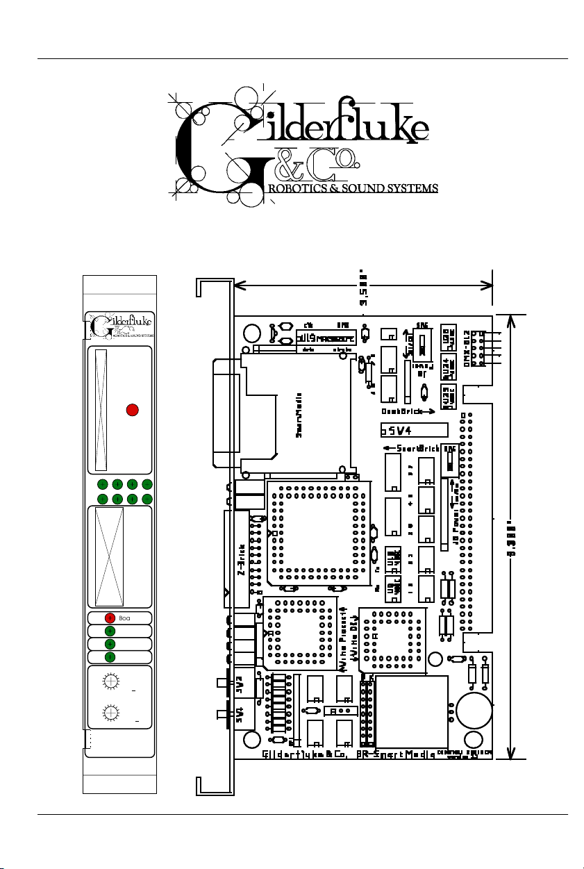
BR-SmartMedia
Printed June 22, 2003
SmartMedia
ABCD
EFGH
Z-Brick
Board Error
DMX-
512
Brain Heart/
Running
Heartbeat
C
D
B
E26A
F
9
MSB
08
1
7
x0h)
(
53
4
Addres
C
D
B
E26A
s
F
9
LSB
08
xh)
(0
1
7
53
4
BR-
SmartMedia
i of vii
Page 2

GILDERFLUKE & CO .• 205 SOUTH FLOWER STREET • BURBANK , CALIFORNIA 91502 • 818/840-9484 • 800/776-5972 • FAX 818/840-9485
AST COAST /FLORIDA OFFICE • 7041 GRAND NATIONAL DRIVE • SUITE 128d • ORLANDO , FL. 32819 • 407/354-5954 • FAX 407/354-5955
E
Safety Disclaimer: Any electronic or mechanical
system has the potential to fail. Certain applications using Gilderfluke & Company equipment may
involve potential risks of death, personal injury or
severe property or environmental damage
(“Critical Application”).
Gilderfluke & Company equipment is not designed, intended, authorized or warranted to be
suitable in life support applications, devices or
systems or other critical applications. Inclusion of
Gilderfluke & Company products in such applications is understood to be fully at the risk of the customer. In order to minimize risks associated with
the customer's applications, adequate design and
operating safeguards should be provided by the
customer to minimize inherent or procedural hazards.
Gilderfluke & Company assumes no liability for
applications assistance, customer produced design, software performance, or infringement of
patents or copyrights. Nor does Gilderfluke &
Company warrant or represent that any license, either express or implied, is granted under any
patent rights, copyright, mask work rights, or other
intellectual property rights of Gilderfluke &
Company covering or relating to any combination,
machine, or process in which Gilderfluke &
Company products or services might be or are
used.
ii of vii
Page 3

GILDERFLUKE & CO .• 205 SOUTH FLOWER STREET • BURBANK , CALIFORNIA 91502 • 818/840-9484 • 800/776-5972 • FAX 818/840-9485
AST COAST /FLORIDA OFFICE • 7041 GRAND NATIONAL DRIVE • SUITE 128d • ORLANDO , FL. 32819 • 407/354-5954 • FAX 407/354-5955
E
BR-SmartMedia Overview ................................... 1
MultiShow mode ................................................... 1
Serial mode ......................................................... 2
‘Dumb’ Brick ........................................................................... 3
Remote Terminal Unit (RTU) .................................... 5
DMX-512 Recorder mode ....................................... 6
On the Front of the BR-SmartMedia .................... 9
Show Running LEDs ............................................... 9
SmartMedia Activity LED ........................................ 9
Z-Brick Connector ................................................. 9
Board Error LED ................................................... 10
DMX-512 LED ...................................................... 10
Brain Heart/Running LED ....................................... 10
Heartbeat LED .................................................... 10
Address Switches ................................................ 10
On the Back of the BR-SmartMedia ................... 12
‘Smart’ Brick Network ........................................... 14
‘J6’ Inputs .......................................................... 14
‘J8’ Inputs .......................................................... 15
PC and Compatible Connections ........................................ 16
Apple Macintosh Connections ............................................. 17
DMX-512 Data In/Out ........................................... 18
Preparing Animation Data for AutoDownloads 19
Serial Port Commands ...................................... 23
Echo Commands ................................................ 24
Echo On .............................................................................. 24
Echo Off .............................................................................. 24
Card Reset ........................................................ 24
Card Status ....................................................... 25
Start Commands ................................................ 27
Start Track ............................................................................ 27
Start Global ......................................................................... 27
Stop Commands ................................................ 27
Stop Track ............................................................................ 27
iii of vii
Page 4

GILDERFLUKE & CO .• 205 SOUTH FLOWER STREET • BURBANK , CALIFORNIA 91502 • 818/840-9484 • 800/776-5972 • FAX 818/840-9485
AST COAST /FLORIDA OFFICE • 7041 GRAND NATIONAL DRIVE • SUITE 128d • ORLANDO , FL. 32819 • 407/354-5954 • FAX 407/354-5955
E
Stop Global ......................................................................... 27
Loop Commands ................................................ 28
Loop Track ........................................................................... 28
Loop Global ......................................................................... 28
Stop at End Commands ....................................... 28
Stop at End Track ................................................................. 28
Stop at End Global ............................................................... 28
Select Show Commands ...................................... 28
Select Show Track ................................................................ 28
Select Show Global .............................................................. 28
Show Pause Commands ...................................... 29
Pause Show ......................................................................... 29
Continue Show .................................................................... 29
AutoDownload .................................................... 29
RealTime Update ................................................ 30
BR-SmartMedia Hardware Configuration ......... 31
Address ............................................................. 31
BR-SmartMedia Software Configuration ........... 34
MultiShow Mode ................................................. 37
Numbering System .............................................................. 37
Input Commands ............................................................... 39
1/4 J6 Input bit 0 .............................................................39
1/4 J6 Input bit 1 .............................................................39
1/4 J6 Input bit 2 .............................................................39
1/4 J6 Input bit 3 .............................................................39
1/4 J6 Input bit 4 .............................................................39
1/4 J6 Input bit 5 .............................................................39
1/4 J6 Input bit 6 .............................................................39
1/4 J6 Input bit 7 .............................................................39
Green Input ....................................................................39
Blue Input ......................................................................39
Ease-In Speed: ..................................................................... 41
PowerOn/E-Stops Go To Show Number ................................. 42
Ease-In Channels ................................................................. 42
Information .......................................................................... 46
Reload Configuration: ......................................................... 46
MIDI Mode ......................................................... 53
DMX-512 ............................................................................. 53
Baud Rate ........................................................................... 53
iv of vii
Page 5

GILDERFLUKE & CO .• 205 SOUTH FLOWER STREET • BURBANK , CALIFORNIA 91502 • 818/840-9484 • 800/776-5972 • FAX 818/840-9485
AST COAST /FLORIDA OFFICE • 7041 GRAND NATIONAL DRIVE • SUITE 128d • ORLANDO , FL. 32819 • 407/354-5954 • FAX 407/354-5955
E
Numbering System .............................................................. 53
VT-52 Compatible Display .................................................... 53
Ease-In Speed ...................................................................... 53
Operating Mode .................................................................. 53
Monitor Channel ................................................................. 54
MIDI Keyboard Channels ...................................................... 54
Voice, Press Velocity, and Release Velocity .......................... 56
String Trigger Channel ......................................................... 56
Edit Strings..... ...................................................................... 56
Analogs to Ease-In: .............................................................. 57
Info ..................................................................................... 57
Reload Configuration: ......................................................... 57
Play a Show: ........................................................................ 57
Save Configuration: ............................................................. 57
Test Shows: .......................................................................... 57
eXit ..................................................................................... 57
Intelix Mode ....................................................... 58
DMX-512 ............................................................................. 58
Baud Rate ........................................................................... 58
Numbering System .............................................................. 58
VT-52 Compatible Display .................................................... 58
Ease-In Speed: ..................................................................... 58
Operating Mode .................................................................. 58
Monitor Channel ................................................................. 59
Intelix Strings ........................................................................ 59
String Trigger Channel ......................................................... 60
Edit Strings..... ...................................................................... 60
Analogs to Ease-In: .............................................................. 60
Info ..................................................................................... 60
Reload Configuration: ......................................................... 60
Play a Show: ........................................................................ 60
Save Configuration: ............................................................. 60
Test Shows: .......................................................................... 60
eXit ..................................................................................... 60
Rexroth Quick Write Mode .................................... 61
DMX-512 ............................................................................. 62
Baud Rate ........................................................................... 62
Numbering System .............................................................. 62
VT-52 Compatible Display .................................................... 62
Ease-In Speed: ..................................................................... 62
Operating Mode .................................................................. 62
Monitor Channel ................................................................. 62
v of vii
Page 6

GILDERFLUKE & CO .• 205 SOUTH FLOWER STREET • BURBANK , CALIFORNIA 91502 • 818/840-9484 • 800/776-5972 • FAX 818/840-9485
AST COAST /FLORIDA OFFICE • 7041 GRAND NATIONAL DRIVE • SUITE 128d • ORLANDO , FL. 32819 • 407/354-5954 • FAX 407/354-5955
E
Rexroth Channels.... ............................................................ 62
Analog Resolution ................................................................ 63
String Trigger Channel ......................................................... 64
Edit Strings..... ...................................................................... 64
Analogs to Ease-In: .............................................................. 64
Reload Configuration: ......................................................... 64
Play a Show: ........................................................................ 64
Save Configuration: ............................................................. 64
Test Shows: .......................................................................... 64
eXit ..................................................................................... 64
Orpan Modes ..................................................... 65
DMX-512 ............................................................................. 66
Baud Rate ........................................................................... 66
Numbering System .............................................................. 66
VT-52 Compatible Display .................................................... 66
Ease-In Speed: ..................................................................... 67
Operating Mode .................................................................. 67
Monitor Channel ................................................................. 67
String Trigger Channel ......................................................... 67
Edit Strings..... ...................................................................... 67
Analogs to Ease-In: .............................................................. 67
Info ..................................................................................... 67
Reload Configuration: ......................................................... 67
Play a Show: ........................................................................ 67
Save Configuration: ............................................................. 67
Test Shows: .......................................................................... 67
eXit ..................................................................................... 67
Moog Motion Base Modes .................................... 68
DMX-512 ............................................................................. 74
Baud Rate ........................................................................... 74
Numbering System .............................................................. 74
VT-52 Compatible Display .................................................... 74
Ease-In Speed ...................................................................... 74
Operating Mode .................................................................. 74
Motion Base ID ..................................................................... 74
Monitor Channel ................................................................. 74
Analog Resolutions .............................................................. 74
String Trigger Channel ......................................................... 75
Edit Strings..... ...................................................................... 75
Oversampling ...................................................................... 75
Analogs to Ease-In ............................................................... 75
Info ..................................................................................... 75
vi of vii
Page 7

GILDERFLUKE & CO .• 205 SOUTH FLOWER STREET • BURBANK , CALIFORNIA 91502 • 818/840-9484 • 800/776-5972 • FAX 818/840-9485
AST COAST /FLORIDA OFFICE • 7041 GRAND NATIONAL DRIVE • SUITE 128d • ORLANDO , FL. 32819 • 407/354-5954 • FAX 407/354-5955
E
Reload Configuration .......................................................... 75
Play a Show ......................................................................... 75
Save Configuration .............................................................. 75
Test Shows ........................................................................... 75
Serial RealTime Update Mode ............................... 76
DMX-512 ............................................................................. 77
Baud Rate ........................................................................... 77
Numbering System .............................................................. 77
VT-52 Compatible Display .................................................... 77
Ease-In Speed ...................................................................... 77
1st Channel Offset .............................................................. 77
Operating Mode .................................................................. 77
Analogs to Ease-In ............................................................... 77
Info ..................................................................................... 77
Reload Configuration .......................................................... 77
Play a Show ......................................................................... 77
Save Configuration .............................................................. 77
Test Shows ........................................................................... 77
eXit ..................................................................................... 77
DMX-512 Recorder Mode ..................................... 78
DMX-512 ............................................................................. 78
Numbering System .............................................................. 78
VT-52 Compatible Display .................................................... 78
Ease-In Speed ...................................................................... 78
Current Show ...................................................................... 78
Record Show ....................................................................... 78
Wipe Show ........................................................................... 79
Analogs to Ease-In ............................................................... 79
Info ..................................................................................... 79
Reload Configuration .......................................................... 79
Play a Show ......................................................................... 79
Save Configuration .............................................................. 79
Test Shows ........................................................................... 79
eXit ..................................................................................... 79
HEXadecimal to Decimal to Percentage ......... 80
vii of vii
Page 8

GILDERFLUKE & CO .• 205 SOUTH FLOWER STREET • BURBANK , CALIFORNIA 91502 • 818/840-9484 • 800/776-5972 • FAX 818/840-9485
AST COAST /FLORIDA OFFICE • 7041 GRAND NATIONAL DRIVE • SUITE 128d • ORLANDO , FL. 32819 • 407/354-5954 • FAX 407/354-5955
E
A note about this manual:
This manual covers the specifics of the BRSmartMedia. To program the BR-SmartMedia
you will also need the PC•MACs manual sections that cover PC•MACs software.
The BR-SmartMedia is often programmed
in ‘Software-only’ or ‘Hardwareless Realtime’
mode. If you are using the PC•MACs MACs-
SMP or MACs-USB for programming your BRSmartMedia through the DMX-512 input,
please refer to the PC•MACs ‘Unlimited’
mode.
The full PC•MACs manual can be downloaded from our web site at:
http:/ /www.gilderfluke.com
viii of viii
Page 9

GILDERFLUKE & CO .• 205 SOUTH FLOWER STREET • BURBANK , CALIFORNIA 91502 • 818/840-9484 • 800/776-5972 • FAX 818/840-9485
AST COAST /FLORIDA OFFICE • 7041 GRAND NATIONAL DRIVE • SUITE 128d • ORLANDO , FL. 32819 • 407/354-5954 • FAX 407/354-5955
E
BR-SmartMedia Overview
The BR-SmartMedia is a unique product in the Gilderfluke &
Company lines. It is a combination of several previous products:
BS-Serial, BS-DMX-Tx, and BR-MultiShow. In all modes, show data
is output through DMX-512 or the Z-Buss. In the ‘serial’ mode, the
card will also output data in a variety of serial formats through a
secondary RS-422 serial port. Built-in serial modes are available
that support MIDI, Moog motion bases, Intelix mixers, and Rexroth
feedback cards. More modes can be added if needed, or you
can write strings for controlling LaserDisks, DVDs, projectors, or
whatever.
BR-SmartMedia in MultiShow mode: Strictly speaking,
when in MultiShow mode, the BR-SmartMedia is neither a
'Smart' Brick nor a 'Dumb' Brick. It is a stand-alone DMX512 output show controller. The BR-SmartMedia can
have up to 265 shows loaded on it. Up to eight of these
shows can be played back at the same time, completely independently of the others. MultiShow mode is
used when:
1) You need ‘off-board’ or ‘centralized’ memory storage for a system that will be running multiple animation sequences simultaneously.
One way you might want to think of MultiShow mode
is as eight separate distributed 'Dumb' Brick systems,
which happen to share the same DMX-512 output
cable. All eight sequencers can run completely independently of the others. Each has its own inputs that tells
it when to start or stop. Each can be told to loop one or
more shows, or stop and wait for the next trigger at the
end of the show.
Using the serial port, up to 256 BR-SmartMedia cards
(or any other Gilderfluke & Co. cards) can share the
1 of 81
Page 10

GILDERFLUKE & CO .• 205 SOUTH FLOWER STREET • BURBANK , CALIFORNIA 91502 • 818/840-9484 • 800/776-5972 • FAX 818/840-9485
AST COAST /FLORIDA OFFICE • 7041 GRAND NATIONAL DRIVE • SUITE 128d • ORLANDO , FL. 32819 • 407/354-5954 • FAX 407/354-5955
E
same ‘multidrop’ RS-422 serial network. This can easily interface with commercially made touch screen operator
panels, PCs, or even Internet or telephone modems. The
latter two allow you to control and monitor the system
from around the block or from the other side of the world.
The data from these eight show sequencers are
combined into a single DMX-512 output stream. Up to
256 channels worth of analog or digital output cards,
dimmers and other DMX-512 compatible equipment
can be attached to the DMX-512 output. Any individual
DMX-512 channel can be controlled by any of the eight
sequencers. Its neighbors can be controlled by the
same, or any other sequencer. Even a single digital output bit within a channel can be controlled by a different
sequencer than its neighbors.
Whether any of the sequencers are running or not,
thirty times each second, all 256 channels of show data
are transmitted through the Z-Brick and DMX-512 data
outputs. The DMX-512 output can be used to control
light dimmers, automated spotlights, color changers,
fog and wind machines, or any other pieces of equipment which will accept standard DMX-512 inputs. The ZBrick output can be used for additional digital outputs
through one or more Z-Bricks.
All shows programmed for use in MultiShow mode
must be programmed at thirty frames per second.
BR-SmartMedia in Serial mode: When configured in Serial
mode, the BR-SmartMedia can be used as either a
‘Smart’ or ‘Dumb’ brick. It can be used when:
1) You need to add a DMX-512 or serial output to a
‘Smart’ or ‘Dumb’ Brick system.
2) You have exceeded the onboard flash memory
2 of 81
Page 11

GILDERFLUKE & CO .• 205 SOUTH FLOWER STREET • BURBANK , CALIFORNIA 91502 • 818/840-9484 • 800/776-5972 • FAX 818/840-9485
AST COAST /FLORIDA OFFICE • 7041 GRAND NATIONAL DRIVE • SUITE 128d • ORLANDO , FL. 32819 • 407/354-5954 • FAX 407/354-5955
E
capacity of another Brick card, and need to add
almost unlimited ‘off-board’ memory storage.
3) You want to have ‘centralized’ memory storage, but
only need to run a single sequencer at one time.
Animation and lighting data is stored on the
SmartMedia Flash Card and transmitted out in a DMX512 and/or secondary serial data port. The serial data
can be transmitted in a number of different formats. It
has dedicated modes for controlling MIDI devices,
Moog Motion Bases, Intelix matrix mixers, Rexroth DCC
Servo cards, and more. The second serial port can be
set to operate at baud rates from 2400 baud to 115
KBaud.
1) BR-SmartMedia as a ‘Dumb’ Brick: Switch #4
must be in the ‘Dumb’ Brick position to operate as a
‘Dumb’ Brick. There should never be both ‘Smart’
and ‘Dumb’ Bricks in the same card cage.
Damage may result if there are.
A ‘Dumb’ Brick is typically used in stand alone
applications, where the show runs continuously or
when triggered by an external event. Multiple
‘Dumb’ bricks can be triggered simultaneously, but
will not be automatically synchronized as the Bricks
in a ‘Smart’ Brick system are.
This BR-SmartMedia acts just like any other
Playback-Only 'Dumb' Brick, playing animation
data from the AutoDownload file found on the
SmartMedia Flash Card. The BR-SmartMedia can
be set to start and play a show at power up, or only
play when triggered. The start trigger can come
through the four optically isolated trigger inputs, or
the RS-422 serial port. The BR-SmartMedia then
3 of 81
Page 12

GILDERFLUKE & CO .• 205 SOUTH FLOWER STREET • BURBANK , CALIFORNIA 91502 • 818/840-9484 • 800/776-5972 • FAX 818/840-9485
AST COAST /FLORIDA OFFICE • 7041 GRAND NATIONAL DRIVE • SUITE 128d • ORLANDO , FL. 32819 • 407/354-5954 • FAX 407/354-5955
E
uses the show data stored in the AutoDownload file
on the SmartMedia Flash Card to update its outputs at the appropriate frame rate.
The animation sequence which is to be used on
the BR-SmartMedia is usually generated on a
PC•MACs Animation Control System. During programming, the DMX-512 input or RealTime updates through RS-422 serial port can be used so
that you can see the animation sequence as it is
programmed. Once programming is completed
and your show(s) saved to disk, the data is downloaded to the SmartMedia onboard the BRSmartMedia through the serial port.
2) BR-SmartMedia as a 'Smart' Brick: Switch #4 must
be in the ‘Smart’ Brick position to operate as a
‘Smart’ Brick. There should never be both ‘Smart’
and ‘Dumb’ Bricks in the same card cage.
Damage may result if there are.
A ‘Smart’ Brick system is used when you need to
synchronize any number of ‘Bricks’ together on a
‘Smart’ Brick Network under the control of a single
‘Smart’ Brick Brain. The Brain itself allows shows to be
triggered at specific times of the day using a real
time clock and the Brains’ 365 day schedule, and
locked (synchronized) to Smpte time code,
LaserDisks and DVDs, or the Brains’ own internal or
external clock. A single Brain and ‘Smart’ Brick network can run a single time line at one time.
This BR-SmartMedia acts just like any other
Playback-Only 'Smart' Brick, playing animation
data from a the AutoDownload file on the
SmartMedia Flash Card. As a 'Smart' Brick, it requires a 'Smart' Brick Brain to run. The 'Smart' Brick
4 of 81
Page 13

GILDERFLUKE & CO .• 205 SOUTH FLOWER STREET • BURBANK , CALIFORNIA 91502 • 818/840-9484 • 800/776-5972 • FAX 818/840-9485
AST COAST /FLORIDA OFFICE • 7041 GRAND NATIONAL DRIVE • SUITE 128d • ORLANDO , FL. 32819 • 407/354-5954 • FAX 407/354-5955
E
Brain tells all the 'Smart' Bricks attached to it (includ-
ing the BR-SmartMedia) where in the show it is. The
BR-SmartMedia then uses this information to access
the appropriate data in the AutoDownload file on
the SmartMedia Flash Card and update its out-
puts.
The animation sequence which is to be used on
the BR-SmartMedia is usually generated on a
PC•MACs Animation Control System. During programming, the DMX-512 input or RealTime updates through RS-422 serial port can be used so
that you can see the animation sequence as it is
programmed. Once programming is completed
and your show(s) saved to disk, the data is downloaded to the SmartMedia onboard the BRSmartMedia.
In all of the above modes, all 256 channels of
DMX-512 of the AutoDownload file on the
SmartMedia Flash Card are transmitted through
the Z-Brick and/or DMX-512 data outputs. The ZBrick output can be used for additional digital outputs through one or more Z-Bricks. The DMX-512
output can be used to control light dimmers, automated spotlights, color changers, fog and wind
machines, or any other pieces of equipment which
will accept standard DMX-512 inputs.
Using the serial port, up to 256 BR-SmartMedia
cards (or any other Gilderfluke & Co. cards) can
share the same ‘multidrop’ RS-422 serial network.
This can easily interface with commercially made
touch screen operator panels, PCs, or even
modems to control and monitor the system from
around the block or from the other side of the world.
5 of 81
Page 14

GILDERFLUKE & CO .• 205 SOUTH FLOWER STREET • BURBANK , CALIFORNIA 91502 • 818/840-9484 • 800/776-5972 • FAX 818/840-9485
AST COAST /FLORIDA OFFICE • 7041 GRAND NATIONAL DRIVE • SUITE 128d • ORLANDO , FL. 32819 • 407/354-5954 • FAX 407/354-5955
E
BR-SmartMedia as a Remote Terminal Unit (RTU): In this
mode the card receives up to 256 channels of DMX512 data transmitted by a PC•MACs Animation Control
System, or any other source of DMX-512 data. In a hardwareless RealTime PC•MACs system 1, up to sixteen
eight-bit wide channels of animation control data is received through the BR-SmartMedia’s RS-422 serial port. It
uses the DMX-512 or RealTime serial data to update its
outputs. The BR-SmartMedia will retransmit DMX-512
data from channels 0 to 255 (0 to 15 for RealTime serial
data). The DMX-512/RealTime serial inputs allow the BRSmartMedia to be used as a permanent output device
for a Control System, or the DMX-512/RealTime serial
data can be used temporarily until the SmartMedia is
programmed so the BR-SmartMedia can be used as a
'Smart' or ‘Dumb’ Brick.
BR-SmartMedia in DMX-512 Recorder mode: This is a
mode which is used to ‘capture’ an incoming stream of
DMX-512 data. This data can be saved into an
AutoDownload file that can then be used to play back
the sampled DMX-512 just as if it were generated using
a PC•MACs Show Control System. Typically this is used to
sample a lighting system’s output so that the rather expensive lighting board that the lighting designer knows
and loves can be returned to the rental house. The BRSmartMedia then takes the place of the lighting board
in the permanent installation.
A BR-SmartMedia is not normally left in Recorder
1
The ‘Hardwareless Realtime’ Mode of operation of PC•MACs requires a license be purchased to upgrade PC•MACs from ‘Software-Only’ mode. It
allows you to program and review your shows in Real-Time as they are
being programmed. This requires a security key to be entered and validated in the PC•MACs software. If you would like to use this feature but
do not have a security key, contact Gilderfluke & Company to have
your software upgraded.
6 of 81
Page 15

GILDERFLUKE & CO .• 205 SOUTH FLOWER STREET • BURBANK , CALIFORNIA 91502 • 818/840-9484 • 800/776-5972 • FAX 818/840-9485
AST COAST /FLORIDA OFFICE • 7041 GRAND NATIONAL DRIVE • SUITE 128d • ORLANDO , FL. 32819 • 407/354-5954 • FAX 407/354-5955
E
Mode after the data has been sampled. It is switched to
whatever other mode best suits the application.
The second reason you may need the Recorder
Mode menu is that this is where you will find the command to reformat a SmartMedia Flash Card. If the format of a SmartMedia Flash Card is damaged, or if the
Flash Card is reformatted in a PC, it will need to be reformatted. If you reformat a SmartMedia Flash Card on a
PC, it will work OK on a PC, but not in the BR-SmartMedia
until it has been reformatted. We have found that this will
even repair SmartMedia Flash Cards that have stopped
working in MP3 players and other devices that expect
the format to be in the SmartMedia Forum’s standard arrangement. PCs do not format Flash Cards to this standard.
The DMX-512 standard was developed by the United States
Institute for Theatrical Technology (USITT) for a high speed (250
KBaud) asynchronous serial data link. Although it was originally
designed for controlling light dimmers, it is now supported by
hundreds of suppliers throughout the world for controlling all kinds
of theatrical equipment.
Even though the DMX-512 standard calls for up to 512 channels of data, the DMX-512 transmission from PC•MACs is limited
to 256 eight bit wide channels. You can address your DMX-512
compatible output devices to respond to any address between
00 and 255. Addresses above the 256th are used in PC•MACs
for transmitting a checksum. The BR-SmartMedia can use this to
verify that the data received from PC•MACs has no transmission
errors in it. If you address a light dimmer or other DMX-512 device
to addresses 256 or 257, you will see this verification data displayed as a flickering pattern.
All 256 channels of data are also transmitted through the Z-
Brick port. Depending on the mode and data stored, 256 or 512
7 of 81
Page 16

GILDERFLUKE & CO .• 205 SOUTH FLOWER STREET • BURBANK , CALIFORNIA 91502 • 818/840-9484 • 800/776-5972 • FAX 818/840-9485
AST COAST /FLORIDA OFFICE • 7041 GRAND NATIONAL DRIVE • SUITE 128d • ORLANDO , FL. 32819 • 407/354-5954 • FAX 407/354-5955
E
channels of DMX-512 can be transmitted. The Z-Brick output can
be used for additional digital outputs through one or more ZBricks. The DMX-512 output can be used to control light dimmers,
automated spotlights, color changers, fog and wind machines,
or any other equipment which will accept standard DMX-512 inputs. Channels where no data is stored in SmartMedia are
cleared when operating as a 'Smart' or 'Dumb' Brick.
The BR-SmartMedia can be mounted in one 1” wide slot in
any of our Brick Card cages. The BR-SmartMedia can be used in
conjunction with any selection of 'Smart' Bricks, 'Smart' Brick Brains,
Electronic FeedBack (EFB) 'Smart' Bricks and Z-Bricks in the same
card cage. Card cages with one, two or sixteen slots are available. The card cages provide all the connections for power supply, control signals and outputs that any Brick card will need.
Several different styles of output connectors are available on the
one and two slot card cages. The sixteen slot card cage mounts
in seven inches of standard 19” rack space (4-1/2“ of space behind the panel). In some applications you may need to mount a
single BR-SmartMedia. This can be done by mounting the BRSmartMedia on standoffs, and connecting to the BRSmartMedia's edge connector with a mating connector. We usually recommend a card cage.
Power requirements for each BR-SmartMedia are 18 to 24
VDC. The BR-SmartMedia draws approximately 200 ma..
The BR-SmartMedia is a design upgrade from all earlier ver-
sions of the BR-MultiShow, BS-Serial, and BS-DMX-Tx. The chief differences are:
1) Combines the function of three different cards.
2) SmartMedia for show data storage instead of Eprom.
This allows shows to be programmed and downloaded
in seconds.
3) Operates as either a ‘Smart’ or ‘Dumb’ Brick
8 of 81
Page 17

GILDERFLUKE & CO .• 205 SOUTH FLOWER STREET • BURBANK , CALIFORNIA 91502 • 818/840-9484 • 800/776-5972 • FAX 818/840-9485
AST COAST /FLORIDA OFFICE • 7041 GRAND NATIONAL DRIVE • SUITE 128d • ORLANDO , FL. 32819 • 407/354-5954 • FAX 407/354-5955
E
4) Runs cooler with a switching power supply.
9 of 81
Page 18

GILDERFLUKE & CO .• 205 SOUTH FLOWER STREET • BURBANK , CALIFORNIA 91502 • 818/840-9484 • 800/776-5972 • FAX 818/840-9485
AST COAST /FLORIDA OFFICE • 7041 GRAND NATIONAL DRIVE • SUITE 128d • ORLANDO , FL. 32819 • 407/354-5954 • FAX 407/354-5955
E
On the Front of the BR-SmartMedia
A) Show Running LEDs: These eight LEDs are lit to show that a se-
quencer is running a show. In MultiShow mode, all eight of these
LEDs are used. In any of the single sequencer modes of opera-
tion, only the ‘Sequencer A’ LED will light to show that it is running
a show (or advancing frames if being operated from a Smart Brick
Brain as a ‘Smart’ Brick).
During ‘Ease-Ins’, these LEDs will flash to show that the se-
quencers are in the process of doing an Ease-In.
Some operations that monopolize the CPU on the BRSmartMedia will shut down all other normal operations. During
these times, these eight LEDs will flash in a circular chase pattern
to show the card is occupied. Some of the things that will cause
this condition are:
a) Doing initial mapping of the AutoDownload file on the
SmartMedia Flash Card the first time it is plugged in. The BR-
SmartMedia must read the entire AutoDownload file off the
SmartMedia Flash Card to find where Windows has hidden
all of its parts.
b) During AutoDownloads.
c) Configuration downloads.
d) Configuration uploads.
B) SmartMedia Activity LED: This LED lights when any extended
SmartMedia operation is going on. Just like the light on the front
of a floppy disk drive, you should not remove the SmartMedia
Flash Card or power down the BR-SmartMedia card while this LED
is lit.
C) Z-Brick Connector: This twenty pin IDS connector is used to con-
nect to one or more Z-Bricks. When enabled, the BR-SmartMedia
outputs data from the DMX-512 input or onboard SmartMedia to
this connector. The format of the data is as follows:
IDS pin # SIGNAL
1 Data bit 0
2 Data bit 1
3 Data bit 2
4 Data bit 3
5 Data bit 4
6 Data bit 5
10 of 81
Page 19

GILDERFLUKE & CO .• 205 SOUTH FLOWER STREET • BURBANK , CALIFORNIA 91502 • 818/840-9484 • 800/776-5972 • FAX 818/840-9485
AST COAST /FLORIDA OFFICE • 7041 GRAND NATIONAL DRIVE • SUITE 128d • ORLANDO , FL. 32819 • 407/354-5954 • FAX 407/354-5955
E
7 Data bit 6
8 Data bit 7
9 Address bit 0
10 Address bit 1
11 Address bit 2
12 Address bit 3
13 Address bit 4
14 Address bit 5
15 Address bit 6
16 Address bit 7
17 ground
18 ground
19 Strobe/
20 Reset/
When the address and data lines are valid, the rising edge of
the Strobe line will latch the data into the addressed outputs.
D) Board Error LED: This LED will flash when:
1) BR-SmartMedia has just booted
2) An error is found in the DMX-512 data checksum
3) An error is found in the 'Smart' Brick Network checksum
E) DMX-512 LED: This LED will be lit when the BR-SmartMedia is re-
ceiving DMX-512 or RealTime updates via the RS-422 serial port.
F) Brain Heart/Running LED: ‘Smart’ Brick mode: The heartbeat from
the 'Smart' Brick Brain is transmitted throughout the system over
the 'Smart' Brick Network. The presence of a healthy heartbeat
means that the data on the 'Smart' Brick Network is getting
through cleanly. If it ever stutters or flashes erratically (or not at
all), then there is a problem with the 'Smart' Brick Brain, the 'Smart'
Brick Network, or the BR-SmartMedia. As the DMX-512 takes precedence over the 'Smart' Brick Network, this LED will go dark whenever a DMX-512 signal is present.
G) Heartbeat LED: This LED Flashes continuously while the CPU is run-
ning. If it ever stops for more than a fraction of a second, the
'Deadman' circuit in the BR-SmartMedia will automatically reset
the CPU. While performing an Ease-In, the heart rate will double.
H) Address Switches: These two rotary switches on the front of the
BR-SmartMedia are used to set the address of the RS-422 serial
port where this card will be found. Normally, only one card is set
to use any one address. If more than one card is set to the same
11 of 81
Page 20

GILDERFLUKE & CO .• 205 SOUTH FLOWER STREET • BURBANK , CALIFORNIA 91502 • 818/840-9484 • 800/776-5972 • FAX 818/840-9485
AST COAST /FLORIDA OFFICE • 7041 GRAND NATIONAL DRIVE • SUITE 128d • ORLANDO , FL. 32819 • 407/354-5954 • FAX 407/354-5955
E
address, then the serial ports can not be attached to the same
RS-422 multidrop network at the same time.
The RS-422 serial address for the BR-SmartMedia is set using
Hexadecimal numbers on these switches. The first digit of the
Hexadecimal address is set on the upper of the two switches. The
second digit of the hexadecimal address is set on the lower of the
two switches. If you are not sure how these translate from decimal
numbers, a chart at the end of every Gilderfluke & Company
manual will show you the equivalent numbers.
12 of 81
Page 21

GILDERFLUKE & CO .• 205 SOUTH FLOWER STREET • BURBANK , CALIFORNIA 91502 • 818/840-9484 • 800/776-5972 • FAX 818/840-9485
AST COAST /FLORIDA OFFICE • 7041 GRAND NATIONAL DRIVE • SUITE 128d • ORLANDO , FL. 32819 • 407/354-5954 • FAX 407/354-5955
E
On the Back of the BR-SmartMedia
The BackPlane connections to the BR-SmartMedia is through a sixty posi-
tion double sided edge connector (thirty connections on each side on .1”
centers). This is normally plugged into a card cage, but can also be used
with an IDS or other discrete edge connectors.
The first ten positions are used for the ‘Smart’ Brick Network and J8 con-
nection ('Smart' Brick Network or optically isolated triggers, Depending on
the position of Switch #4 the ‘Smart/Dumb Brick Switch’) and the primary RS422 Serial Port (used for configuration and serial commands). They are normally bussed between all the cards in the card cage (although they can be
separated by cutting the lines if desired).
The next forty positions are used to connect the majority of the BR-
SmartMedia signals to the output cabling.
The last ten positions are used to provide power to the BR-SmartMedia.
Five pins are used for the positive connection and five are used for ground.
This provides a higher current capacity than single pins would.
The pinout of this connector is as follows:
output wire # Edge pin # color wire function
J8/BrickNet Black 1 brown J8 Common (black)/Smart BrickNet Data -
J8/BrickNet White 2 red J8 ‘D’ (white) input/'Smart' BrickNet Data +
J8/BrickNet Red 3 orange J8 ‘B’ (red) input/'Smart' BrickNet Clock +
Serial Port red #3 4 yellow TxD + out from BR-SmartMedia
J8/BrickNet Green 5 green J8 ‘A’ (green) input/'Smart' BrickNet Clock -
Serial Port Black #2 6 blue TxD - out from BR-SmartMedia
J8/BrickNet Yellow 7 violet J8 Status (yellow) out/'Smart' Brick Strobe +
Serial Port Yellow #5 8 gray Rx + in to BR-SmartMedia
J8/BrickNet Blue 9 white J8 ‘C’ (blue) input/'Smart' BrickNet Strobe -
Serial Port green #4 10 black Rx -in to BR-SmartMedia
Ribbon cable #1 11 brown 1/4 J6 in Ground
Ribbon cable #2 12 red 1/4 J6 in bit 7
Ribbon cable #3 13 orange 1/4 J6 in bit 6
Ribbon cable #4 14 yellow 1/4 J6 in bit 5
Ribbon cable #5 15 green 1/4 J6 in bit 4
Ribbon cable #6 16 blue 1/4 J6 in bit 3
Ribbon cable #7 17 violet 1/4 J6 in bit 2
Ribbon cable #8 18 gray 1/4 J6 in bit 1
Ribbon cable #9 19 white 1/4 J6 in bit 0
Ribbon cable #10 2 0 black 1/4 J6 in + Supply
13 of 81
Page 22

GILDERFLUKE & CO .• 205 SOUTH FLOWER STREET • BURBANK , CALIFORNIA 91502 • 818/840-9484 • 800/776-5972 • FAX 818/840-9485
AST COAST /FLORIDA OFFICE • 7041 GRAND NATIONAL DRIVE • SUITE 128d • ORLANDO , FL. 32819 • 407/354-5954 • FAX 407/354-5955
E
Ribbon cable #11 2 1 brown secondary RS-422 ground
Ribbon cable #12 2 2 red secondary RS-422 Serial Rx - data into card
Ribbon cable #13 2 3 orange secondary RS-422 Serial Rx + data into card
Ribbon cable #14 2 4 yellow secondary RS-422 Serial Tx - data out of card
Ribbon cable #15 2 5 green secondary RS-422 Serial Tx + data out of card
Ribbon cable #16 26 blue secondary RS-422 ground
Ribbon cable #17 2 7 violet Green Input negative
Ribbon cable #18 28 gray Green Input positive
Ribbon cable #19 2 9 white Blue Input negative
Ribbon cable #20 3 0 black Blue Input positive
Ribbon cable #21 3 1 brown MIDI n/c (MIDI DIN pin #3)
Ribbon cable #22 32 red MIDI Tx - (MIDI DIN pin #5)
Ribbon cable #23 33 orange MIDI ground (MIDI DIN pin #2)
Ribbon cable #24 3 4 yellow MIDI Tx + (MIDI DIN pin #4)
Ribbon cable #25 3 5 green secondary RS-422 TxD - out from card (ver. 1.1+)
Ribbon cable #26 3 6 blue ground
Ribbon cable #27 3 7 violet secondary RS-422 TxD + out from card (ver. 1.1+)
Ribbon cable #28 3 8 gray ground
Ribbon cable #29 3 9 white secondary RS-422 Serial Rx - in to card (ver. 1.1+)
Ribbon cable #30 4 0 black ground
Ribbon cable #31 4 1 brown secondary RS-422 Serial Rx + in to card (ver. 1.1+)
Ribbon cable #32 4 2 red ground
Ribbon cable #33 4 3 orange
Ribbon cable #34 4 4 yellow
Ribbon cable #35 4 5 green
Ribbon cable #36 4 6 blue
Ribbon cable #37 4 7 violet
Ribbon cable #38 4 8 gray
Ribbon cable #39 4 9 white
Ribbon cable #40 5 0 black
n/a 51 black power supply ground
n/a 52 black power supply ground
n/a 53 black power supply ground
n/a 54 black power supply ground
n/a 55 black power supply ground
n/a 56 red + power supply input
n/a 57 red + power supply input
n/a 58 red + power supply input
n/a 59 red + power supply input
n/a 60 red + power supply input
14 of 81
Page 23

GILDERFLUKE & CO .• 205 SOUTH FLOWER STREET • BURBANK , CALIFORNIA 91502 • 818/840-9484 • 800/776-5972 • FAX 818/840-9485
AST COAST /FLORIDA OFFICE • 7041 GRAND NATIONAL DRIVE • SUITE 128d • ORLANDO , FL. 32819 • 407/354-5954 • FAX 407/354-5955
E
Note that on BR-SmartMedia cards revision 1.1 and later the
secondary serial port is also brought out on the edge connector
on pins #35 through #41. This matches the pinout for the secondary serial port on the BS-BRN-CRD Smart Brick Brain. This allows
you to use the secondary serial port connector found on the first
slot of our BR-CC10 and BR-CC11 three slot card cages for the
secondary serial port.
To simplify wiring to any MACs Animation Control System, the
connectors used on our card cages are what are called 'insulation displacement connectors'. These simply snap on to an entire
cable, automatically 'displacing' the wire insulation and making
contact with the wires within. This means that an entire forty wire
cable can be terminated in seconds. All connectors are polarized, to keep them from being plugged in backwards.
‘Smart’ Brick Network: If Switch #4 is in the ‘Smart’ Brick position, the
BR-SmartMedia will be operating as a ‘Smart’ Brick. The ‘Smart’ Brick
Network normally found on a ‘Smart’ Brick is brought out on the
edge connector. When plugged into any Gilderfluke & Co. Brick
card cage, this will be brought out on a RJ-12 connector on the
card cage. There should never be both ‘Smart’ and ‘Dumb’ Bricks
in the same card cage. They share the same pins on the edge
connector and backplane. Damage may result if both are installed in the same card cage.
The ‘Smart’ Brick Network signals to the BR-SmartMedia are
brought in through a six position RJ-12 (six position, six conductor
modular telephone style connector) on the card cage. Facing
the end of the cable with the release latch upwards, its pin out is
as follows:
COLOR SIGNAL NAME:
LEFT #1 white Smart Brick Net Data +
#2 black Smart Brick Net Data -
#3 red Smart Brick Net Clock +
#4 green Smart Brick Net Clock #5 yellow Smart Brick Net Strobe +
RIGHT #6 blue Smart Brick Net Strobe -
‘J6’ Inputs: If the BR-SmartMedia is acting as a 'Dumb' Brick, then
Switch 5 is used to select whether the ‘J6’ power for the optoisolators is provided by the same power supply as the BR-SmartMedia,
or is provided by an external isolated source. When operating as a
'Smart' Brick, this switch has no effect.
15 of 81
Page 24
)
(
(
2
4
(g
6
7
(grey)
9
)
(
(
(g
6
7
(grey)
9
GILDERFLUKE & CO .• 205 SOUTH FLOWER STREET • BURBANK , CALIFORNIA 91502 • 818/840-9484 • 800/776-5972 • FAX 818/840-9485
AST COAST /FLORIDA OFFICE • 7041 GRAND NATIONAL DRIVE • SUITE 128d • ORLANDO , FL. 32819 • 407/354-5954 • FAX 407/354-5955
E
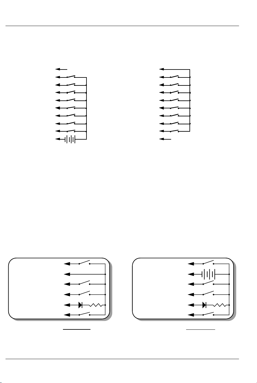
The 1/4 J6 Input is optically isolated. It can be set to run from
an external power source (default configuration) or the same
power as the Rack Smart Brick Brain. This is selected by moving
Switch 5 as shown on the board.
Brown) PIN #1
red) PIN #
(orange) PIN #3
(yellow) PIN #
reen) PIN #5
(blue) PIN #
(violet) PIN #
PIN #8
(white) PIN #
(black) PIN #10
+
xternal Power
GROUND (not used
DATA BIT 7
DATA BIT 6
DATA BIT 5
DATA BIT 4
DATA BIT 3
DATA BIT 2
DATA BIT 1
DATA BIT 0
+ 5 to 24 VDC SUPPLY
Brown) PIN #1
red) PIN #2
(orange) PIN #3
(yellow) PIN #4
reen) PIN #5
(blue) PIN #
(violet) PIN #
PIN #8
(white) PIN #
(black) PIN #10
GROUND
DATA BIT 7
DATA BIT 6
DATA BIT 5
DATA BIT 4
DATA BIT 3
DATA BIT 2
DATA BIT 1
DATA BIT 0
SUPPLY (not used
Internal Power
‘J8’ Inputs: If Switch #4 is in the ‘Dumb’ Brick position, the BR-
SmartMedia will be operating as a ‘Dumb’ Brick. The trigger inputs
and status output normally found on a ‘Dumb’ Brick are brought
out on the edge connector. When plugged into any Gilderfluke &
Co. Brick card cage, this will be brought out on a RJ-12 connector on the card cage. There should never be both ‘Smart’ and
‘Dumb’ Bricks in the same card cage. They share the same pins
on the edge connector and backplane. Damage may result if
both are installed in the same card cage.
There are four optically isolated digital inputs which can be
used to start, stop, pause or select specific show sequences to
play. Facing the end of the wire, with the latch upwards, the
pinout of a standard ‘J8’ cable is as follows.
WHITE #1 (Input 'D')
BLACK #2 (common)
RED #3 (Input 'B')
GREEN #4 (Input 'A')
LED
2.2K-4.7k
YELLOW #5 (status out)
BLUE #6 (Input 'C')
J8 with Sw8 set for INTERNAL power
Any event can be triggered on either the ‘closing’ or ‘opening’
edge of any input. A ‘closing’ is when you apply a voltage to an
16 of 81
WHITE #1 (Input 'D')
BLACK #2 (common)
RED #3 (Input 'B')
GREEN #4 (Input 'A')
YELLOW #5 (status out)
BLUE #6 (Input C')
J8 with Sw8 set for
+ 12 to 24 VDC SUPPLY
+
LED
2.2K-4.7k
EXTERNAL power
Page 25

GILDERFLUKE & CO .• 205 SOUTH FLOWER STREET • BURBANK , CALIFORNIA 91502 • 818/840-9484 • 800/776-5972 • FAX 818/840-9485
AST COAST /FLORIDA OFFICE • 7041 GRAND NATIONAL DRIVE • SUITE 128d • ORLANDO , FL. 32819 • 407/354-5954 • FAX 407/354-5955
E
input. An ‘opening’ is when that voltage is removed. The inputs
can be triggered on any voltage from 12 to 24 VDC. If you don’t
have an external source of power for these two inputs, you can
‘steal’ some juice from the BR-SmartMedia’s power supply connec-
tions. Just put the ‘J8 Power’ switch in the ‘Internal’ position.
Power Supply: The last ten contacts of the BR-SmartMedia’s edge
connector are used for the power supply connections. The BR-
SmartMedia can be run from any supply voltage from 9 to 24
VDC.
The power supply input is protected from reversed polarity. An
idle BR-SmartMedia draws only about 150 milliamperes. The LEDs
on its face will usually draw far more current than the BRSmartMedia itself.
Primary RS-422 Serial Port: This is used for configuration, uploading
a n d d o w n l o a d i n g c o n f i g u r a t i o n s , s t a t u s i n q u i r i e s ,
AutoDownloading show data to SmartMedia, and serial port
RealTime updates. It is compatible with all the RS-422 Serial Ports
and protocols used on Gilderfluke & Company products.
The four active lines on this connector are bussed to the
backplane of the card cage. This allows you to communicate to a
whole card cage full of BR-SmartMedia, 'Smart' Brick Brains,
Electronic FeedBack (EFB) 'Smart' Bricks and other cards through
the connector on the card cage. They just need to be set to different addresses.
The serial data signals from the BR-SmartMedia are brought
out on a six position RJ-12 (six position, six conductor modular
telephone style connector) on the card cage. Facing the end of
the cable with the release latch upwards, its pin out is as follows:
COLOR SIGNAL NAME:
LEFT #1 white Signal Ground
#2 black - Serial data out from card
#3 red + Serial data out from card
#4 green - Serial data in to card
#5 yellow + Serial data in to card
RIGHT #6 blue Signal Ground
PC and Compatible Connections: If you are only talking to a
single BR-SmartMedia and your wire length is short, you may be
able to simply cross wire the RS-232 serial port on your PC to talk
to the BR-SmartMedia. This does not work on all PCs, as some
don’t swing their RS-232 outputs as far as they should. If it does
17 of 81
Page 26
t
GILDERFLUKE & CO .• 205 SOUTH FLOWER STREET • BURBANK , CALIFORNIA 91502 • 818/840-9484 • 800/776-5972 • FAX 818/840-9485
AST COAST /FLORIDA OFFICE • 7041 GRAND NATIONAL DRIVE • SUITE 128d • ORLANDO , FL. 32819 • 407/354-5954 • FAX 407/354-5955
E
not work with your PC, you may need to get a RS-232 to RS-422
converter to talk to the BR-SmartMedia. To cross wire the RS422/RS-485 signals from the BR-SmartMedia to the RS-232 serial
port of an IBM compatible, cross connect the signals as follows:
DB-25 DE-9 Signal Signal from/to BR-SmartMedia
2 3 DATA OUT - Serial data into card (#4 green)
3 2 DATA IN - Serial data out from card (#2 black)
7 5 GROUND Signal Ground (#1 white or #6 blue)
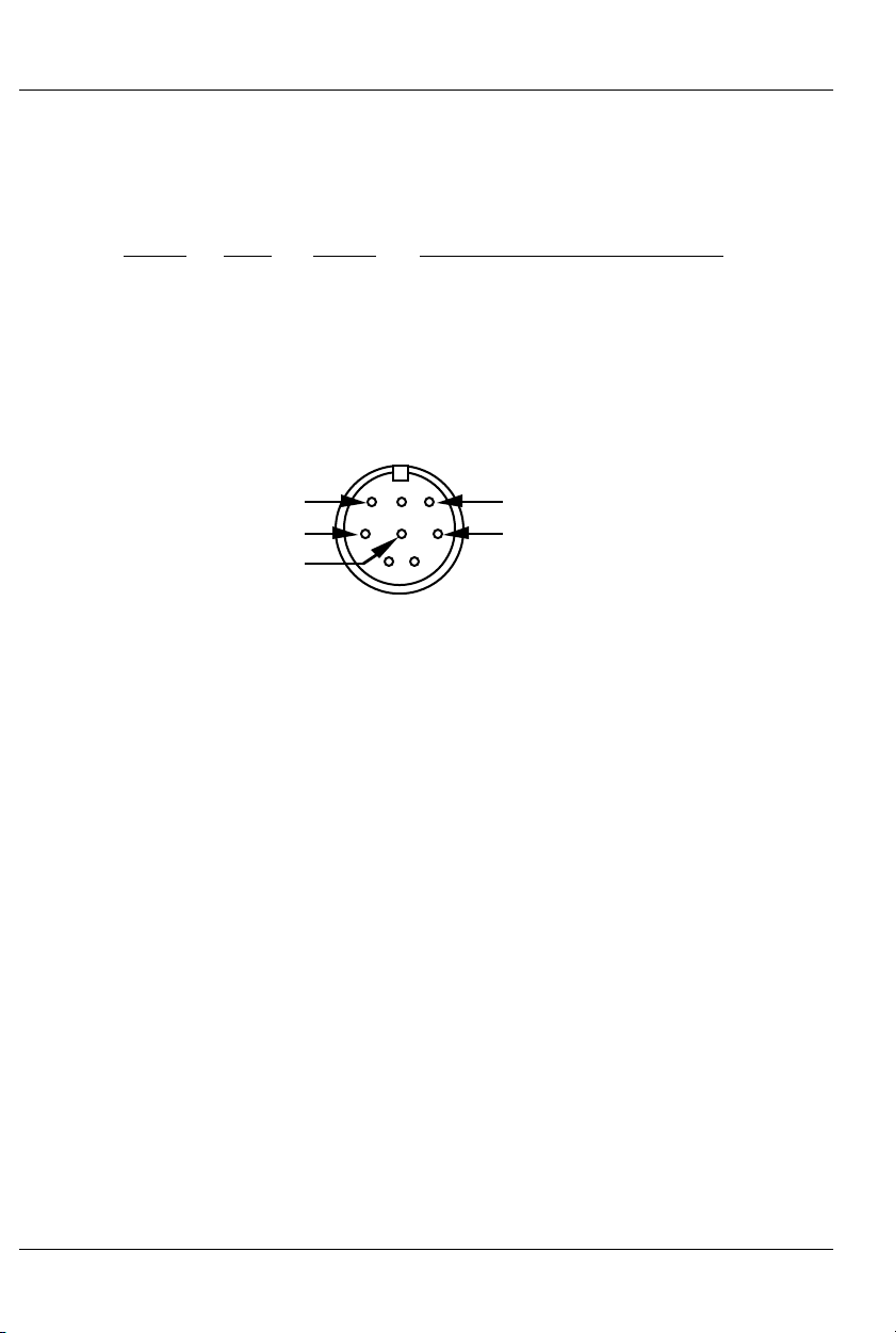
Apple Macintosh Connections: Apple Macintosh computers
have true RS-422 serial ports built in. To connect to the BRSmartMedia, the pin out is as follows (view is of male connector
facing the end of the cable):
o + serial data in to card (#5 yellow)
to - serial data in to card (#4 green)
signal ground (#1 blue or #6 white)
678
345
12
from + serial data out from card (#3 red)
from - serial data out from card (#2 black)
The BR-SmartMedia expects to see the serial data in the fol-
lowing format:
ONE START BIT
EIGHT DATA BITS
ONE STOP BIT
BR-SmartMedia responds appropriately to all commands
which are used by other Gilderfluke & Co. serially controlled devices. These are used for configuration, uploading and downloading configurations, status inquiries, AutoDownloading show data
to SmartMedia, and serial port RealTime updates. It will ignore all
commands which are not addressed to it, or not appropriate for it
to respond to. This allows it to share the same RS-422 serial buss
with additional BR-SmartMedia, Digital Audio Repeaters, 'Smart'
Brick Brains and any other serially controlled devices. The only requirement is that each unit be addressed to a different location.
Secondary RS-422 Serial Port: This is used for sending serial data
from the BR-SmartMedia while it is in any of the ‘Serial’ modes. It is
compatible with all the RS-422 Serial Ports and protocols used on
Gilderfluke & Company products.
The serial data signals from the BR-SmartMedia are brought
out on the edge connector. In a three slot card cage, hardware
18 of 81
Page 27

GILDERFLUKE & CO .• 205 SOUTH FLOWER STREET • BURBANK , CALIFORNIA 91502 • 818/840-9484 • 800/776-5972 • FAX 818/840-9485
AST COAST /FLORIDA OFFICE • 7041 GRAND NATIONAL DRIVE • SUITE 128d • ORLANDO , FL. 32819 • 407/354-5954 • FAX 407/354-5955
E
versions 1.1 and later will also bring out the secondary serial port
on the ‘aux.’ serial port from card cage slot #1. This is a six position RJ-12 (six position, six conductor modular telephone style
connector) on the card cage. Facing the end of the cable with
the release latch upwards, its pin out is as follows:
COLOR SIGNAL NAME:
LEFT #1 white Signal Ground
#2 black - Serial data out from card
#3 red + Serial data out from card
#4 green - Serial data in to card
#5 yellow + Serial data in to card
RIGHT #6 blue Signal Ground
DMX-512 Data In/Out: Ten pin Male header connector. The BR-
SmartMedia will stop listening to the 'Smart' Brick network whenever there is a DMX-512 signal present on this input.
The DMX-512 standard was developed by the United States
Institute for Theatrical Technology (USITT) for a high speed (250
KBaud) asynchronous serial data link. Although it was originally designed for controlling light dimmers, it is now supported by hundreds of suppliers throughout the world for controlling all kinds of
theatrical equipment.
Even though the DMX-512 standard calls for 512 channels of
data, the DMX-512 transmission from PC•MACs is limited to 256
eight bit wide channels. You can address your DMX-512 compatible output devices to respond to any address between 00 and
255. Addresses above the 256th are used in PC•MACs for transmitting a checksum. The BR-SmartMedia can use this to verify that
the data received from PC•MACs has no transmission errors in it. If
you address a light dimmer or other DMX-512 device to addresses
256 or 257, you will see this verification data displayed as a flickering pattern. Note that at frame rates higher than sixty FPS, not
all 256 channels can be transmitted through the DMX-512 output.
The DMX-512 standard calls out a 5 pin XLR connector or
screw terminals for all connections. All card cages will provide either screw terminals or other appropriate connection for attaching the DMX-512 input and output.
19 of 81
Page 28

GILDERFLUKE & CO .• 205 SOUTH FLOWER STREET • BURBANK , CALIFORNIA 91502 • 818/840-9484 • 800/776-5972 • FAX 818/840-9485
AST COAST /FLORIDA OFFICE • 7041 GRAND NATIONAL DRIVE • SUITE 128d • ORLANDO , FL. 32819 • 407/354-5954 • FAX 407/354-5955
E
Preparing Animation Data for AutoDownloads
The Eprom Memories used for the original 'Brick' products manufactured
by Gilderfluke & Company each contained one channel (eight bits) worth
of data. Later products used Eproms which contained several channels
each. The Flash Memories used on the BR-MiniBrick8, BR-MultiBrick32, BRANA, BR-EFB and BR-SmartMedia use a MultiChannel format with a complex
header to allow them to be AutoDownloaded from PC•MACs. The following
instructions apply to all of our cards that use AutoDownload files.
After you have finished programming your show(s), files are
AutoDownloaded from PC•MACs by:
1) Selecting the 'Save as AutoDownload...' command from the 'File'
pulldown.
2) Use the ‘Add’ button to select any additional show(s) you would
like to be saved into this AutoDownload file.
3) Use the ‘Promote’ and ‘Demote’ buttons to move selected show(s)
into the order you would like to save them in the AutoDownload
file on the SmartMedia Flash Card.
4) Select the ‘first show’ and what will happen to the BR-SmartMedia
on power up. If you will be operating the BR-SmartMedia as a
'Smart' Brick, then set the power up action to ‘wait’. If you have set
the BR-SmartMedia to ‘wait’ at power up, then the first frame of
the show you have selected will be output on the DMX-512 and
Z-Brick outputs. This setting is not needed if operating the BRSmartMedia in MultiShow mode, as these settings are made for
each sequencer in the MultiShow setup menus.
5) Set what will happen on each of the four ‘J8’ optoisolated inputs if
you will be operating the BR-SmartMedia as a 'Dumb' Brick or in
MultiShow mode. You can ignore these settings if you will be running it as a 'Smart' Brick. This setting is not needed if operating the
BR-SmartMedia in MultiShow mode. In MultiShow mode, there are
ten inputs that are set up in the MultiShow setup menus.
6) Select each show to be downloaded one at a time and set:
a) what will happen at the end of each show.
b) Whether it can be ‘stepped on’.
if you will be operating the BR-SmartMedia as a 'Dumb' Brick or
in MultiShow mode. You can ignore these settings if you will be
running it as a 'Smart' Brick, because the Smart Brick Brain determines what happens at the end of each show. When operating
20 of 81
Page 29

GILDERFLUKE & CO .• 205 SOUTH FLOWER STREET • BURBANK , CALIFORNIA 91502 • 818/840-9484 • 800/776-5972 • FAX 818/840-9485
AST COAST /FLORIDA OFFICE • 7041 GRAND NATIONAL DRIVE • SUITE 128d • ORLANDO , FL. 32819 • 407/354-5954 • FAX 407/354-5955
E
as a ‘Dumb’ Brick, any show which
can
be stepped upon can be
interrupted mid-show by a new show start coming in. Any show
which
can not
be stepped upon will ignore all additional start
commands while it is still playing. This setting is not needed if operating the BR-SmartMedia in MultiShow mode.
7) Set the ‘Brick Serial Address’ to send the AutoDownload file to. This
is the serial address of the BR-SmartMedia you want it to be received by. All other cards will ignore the data being sent to this
one card. The address is often the same as the ‘start’ channel set
in the next step.
8) Set the 'first channel' and 'last channel' boxes to set the number
channels you want to go into this AutoDownload file. Be sure to
allow for enough extra channels for any Z-Bricks or DMX-512 lighting channels that might be attached to the BR-SmartMedia.
9) The ‘Calculate Brick Start Frames’ checkbox must always be
checked.
10) The ‘Save Brick Start’ checkbox should not be checked.
11) You can quickly test if the BR-SmartMedia is attached to the serial
port properly by hitting the ‘Reset BR-MiniBrick8’ button. Of course,
this will also erase any show data that was already in the BRSmartMedia’s memory. PC•MACs will report if the Reset was successful or not. You don’t need to worry about this if you are going
to ‘drag & drop’ program the SmartMedia on your computer.
12) Press the ‘Build’ or ‘Download’ button to begin the saving process.
a) ‘Build’ will just save the AutoDownload file to your disk, with-
out sending it to the BR-SmartMedia. This is used if you are
going to then drag the AutoDownload file to a SmartMedia
Flash Card that is inserted into your computer (or an external SmartMedia reader/writer).
b) ‘Download’ will save the file to disk and send it to the BR-
SmartMedia Flash Card.
In either case, a standard file save dialog will open. Double
check the Directory location and name the file as desired. It defaults to the name of the first show in the list. You can tell
Windows to save the file to a different directory, if needed.
PC•MACs will warn you if a file already exists in this location with
this same name. Hit OK to save the data to a file, or change the
name & hit OK if you want to preserve the older file.
After doing an AutoDownload, if you press the ‘Report’ button, PC•MACs
21 of 81
Page 30

GILDERFLUKE & CO .• 205 SOUTH FLOWER STREET • BURBANK , CALIFORNIA 91502 • 818/840-9484 • 800/776-5972 • FAX 818/840-9485
AST COAST /FLORIDA OFFICE • 7041 GRAND NATIONAL DRIVE • SUITE 128d • ORLANDO , FL. 32819 • 407/354-5954 • FAX 407/354-5955
E
will display the information about the AutoDownload file you just saved. This
information is also saved in a text file with the same name as the Flash
Memories, but with the extension of ‘.set’. You can open this file with any
text editor (like Notepad or Wordpad). The numbers shown for ‘Brick start’
and ‘Brick end’ are what you need to enter into the 'Smart' Brick Brain to
set the start and end of each show (If you will be running the BRSmartMedia as a 'Smart' Brick). The ‘Eprom Memory start’ and ‘Eprom
Memory end’ are the actual locations of the shows in the AutoDownload
file on the SmartMedia Flash Card. The number shown for the ‘Eprom
Memory End’ for the last show in this file set is the last byte which will be
saved into the AutoDownload file on the SmartMedia Flash Card. If your
SmartMedia is smaller than this number, you will need to use a larger Flash
Card.
The AutoDownload file that PC•MACs automatically generates will have
the extension of filename.Ann. The 'A' in the extension flags it as a
'AutoDownload' file. The 'nn' is the HEXadecimal address of the first channel
in the AutoDownload set. If you are AutoDownloading to a number of different cards, you can use the same name for all of them without fear of overwriting the others since they will automatically have different ‘extensions’.
This file can be sent to any other BR-SmartMedia at any time using a computer and a terminal program like terminal.exe or our GilderTerm.
HyperTerm.exe will not work for this, because it randomly alters values
above 128 in the AutoDownload file.
If you are programming a BR-SmartMedia, you will probably be creating
the AutoDownload file as described above. Instead of downloading it serially to the BR-SmartMedia card, which can take tens of minutes, you will just
drag and drop program it on your PC. This is done just like copying any PC
file from one disk to another.
The SmartMedia Flash Card is inserted into your computer for programming. If you have a PCMCIA slot on your laptop computer, you will probably
be using a ‘PCMCIA to SmartMedia’ adapter. If you have a desktop machine, you will probably use a ‘USB to SmartMedia’ adapter.
In either case, once the SmartMedia Flash Card is inserted, it is mounted just like any other removable disk drive (Windows will spin for a bit and
say it has ‘found new hardware’ the first time a new brand or size of Flash
Card is inserted). You grab the AutoDownload file, and drop it onto the
SmartMedia Flash Card. Even a multi megabyte file will only take a few seconds to copy. Make sure that you don’t just move a ‘shortcut’ if you are on
a Windows machine. The BR-SmartMedia needs the actual file and not just
its name.
One VERY IMPORTANT precaution you must take with removable media
22 of 81
Page 31

GILDERFLUKE & CO .• 205 SOUTH FLOWER STREET • BURBANK , CALIFORNIA 91502 • 818/840-9484 • 800/776-5972 • FAX 818/840-9485
AST COAST /FLORIDA OFFICE • 7041 GRAND NATIONAL DRIVE • SUITE 128d • ORLANDO , FL. 32819 • 407/354-5954 • FAX 407/354-5955
E
(like SmartMedia Flash Cards) on PCs is that you CAN NOT just eject a
SmartMedia Flash Card. You must first tell the PC to ‘turn off’ or ‘stop’ the
SmartMedia Flash Card. Once the PC says it is OK, then you can eject your
SmartMedia Flash Card. If you do not, you will find that the end of your file
was never written. If you are on a Macintosh, just eject the SmartMedia
Flash Card as you would any other media.
One precaution you will have to take when programming SmartMedia
Flash Cards on a PC is DO NOT REFORMAT them. The formatter on a PC will
format the Flash Card with in a way which does not comply with the
SmartMedia standards (it ignores the physical layout of the SmartMedia
Flash Card sectors). If you have a Flash Card that has been formatted on a
PC, the BR-SmartMedia WILL NOT be able to recognize it. To properly reformat a SmartMedia Flash Card, you will need to use the ‘format’ command
available on the BR-SmartMedia’s ‘DMX-512 Recorder’ menu. This will format
a SmartMedia Flash Card back to the factory standards.
23 of 81
Page 32

GILDERFLUKE & CO .• 205 SOUTH FLOWER STREET • BURBANK , CALIFORNIA 91502 • 818/840-9484 • 800/776-5972 • FAX 818/840-9485
AST COAST /FLORIDA OFFICE • 7041 GRAND NATIONAL DRIVE • SUITE 128d • ORLANDO , FL. 32819 • 407/354-5954 • FAX 407/354-5955
E
Serial Port Commands
The BR-SmartMedia can be accessed through the serial port from any
computer running just about any modem or terminal program. The computer you are using doesn’t even need to have any PC•MACs software installed on it.
Most Gilderfluke & Co. products can be controlled through their RS-422
Serial ports. Up to 256 different cards and devices can be attached to the
same serial lines, to form a complete RS-422 ‘MultiDrop’ network. Operator
panels can be attached anywhere on this network to access and control it,
or you can use a telephone or Internet modem. The latter two allow a system to be accessed from around the block or around the world.
Commands can be addressed to a single card on the network, or all the
cards simultaneously.
One of the easiest and most flexible types of operator interfaces for ac-
cessing the serial network are the many touch screen operator panels.
These are available from a number of different suppliers, and most of them
will easily attach right to our MultiDrop serial network. Most of these allow
you to ‘draw’ whatever buttons and user interface icons on their screens
(using a provided Windows program), attach ASCII strings to these ‘buttons’,
and then download the final configuration to the operator panel so the PC
can be taken away.
Typical modem programs you can use with Gilderfluke & Co. equip-
ment are Terminal.exe (which came with Windows 3.1) and HyperTerm.exe
(which comes with later versions of Windows), or GilderTerm. The shareware
Z-Term or earlier releases of AppleWorks (which included a terminal program) can be used on Macintosh computers.
GilderTerm is available free from Gilderfluke & Co. for use with all of our
products. It can be downloaded from our web page, and is included on all
of our CD-ROMs. GilderTerm has been optimized for use with all Gilderfluke
& Company equipment. All the commands are built in, and it will even let
you use your mouse to select commands.
To use the BR-SmartMedia with a terminal program, just configure it for
9600 baud, no parity, eight data bits, one stop bit and ‘xon/xoff’ handshaking. If you are using GilderTerm, all the settings are preset. All you will need
to do is select the appropriate ‘COM’ port.
24 of 81
Page 33

GILDERFLUKE & CO .• 205 SOUTH FLOWER STREET • BURBANK , CALIFORNIA 91502 • 818/840-9484 • 800/776-5972 • FAX 818/840-9485
AST COAST /FLORIDA OFFICE • 7041 GRAND NATIONAL DRIVE • SUITE 128d • ORLANDO , FL. 32819 • 407/354-5954 • FAX 407/354-5955
E
Echo Commands:
“a”(card address) Echo On:
“b” Echo Off:
The ‘Echo ON’ command will turn on a special mode that will
cause all of the other serial port commands to echo on the selected card. This used when you are setting up serial commands
so you can verify all the commands you are issuing are being received correctly. If the card is operating in MultiShow mode, the
sequencer number (‘A’ through ‘H’) will be included in most of the
echo responses. If you are in any other mode, the sequencer
number will be omitted. In the following examples, the ‘echo’ responses are shown in
If you send “a00”, the echo mode will be turned ON:
card 00h/__0, echo mode on
If you send “*03” to request a specific show on all cards:
card 00h/__0, Sequencer A, requested show 03h/__3 ShoName3
If you send “t00” to start the requested show playing on a specific
card:
card 00h/__0, Sequencer A, starting show 03h/__3 ShoName3
If you send “!00” to start a show looping on a specific card:
card 00h/__0, Sequencer A, looping show 04h/__4 ShoName4
If you send “u” to stop all shows playing on all cards:
card 00h/__0, Sequencer A, stopped show 05h/__5 ShoName5
If you send “u” to stop a card that is already stopped, it will give
you an error message:
card 00h/__0, Sequencer A, not playing or looping __8 ShoName8
Similar error messages will be returned whenever you ask the
card to do something that it can not do at the current time.
The ‘Echo OFF’ command turn off the echo mode on all the
cards in the system.
bold italics
:
“j5AA5” (card address) Card Reset:
This command will erase the AutoDownload file on the
SmartMedia Flash Card on the BR-SmartMedia. Needless to say,
this command is only rarely used in a completed installation.
25 of 81
Page 34

GILDERFLUKE & CO .• 205 SOUTH FLOWER STREET • BURBANK , CALIFORNIA 91502 • 818/840-9484 • 800/776-5972 • FAX 818/840-9485
AST COAST /FLORIDA OFFICE • 7041 GRAND NATIONAL DRIVE • SUITE 128d • ORLANDO , FL. 32819 • 407/354-5954 • FAX 407/354-5955
E
“i” (card address) Card Status:
The status screen is a snapshot image of the current status of
the BR-SmartMedia. If you want to update the status information
displayed, you must hit the ‘Card Status’ command a second
time.
When the BR-SmartMedia receives this command, it will re-
spond with the following information:
a) Company: Gilderfluke & Co.
b) Product name: BR-SmartMedia
c) Current mode of operation
d) Firmware revision number and copyright.
e) Information on the currently loaded AutoDownload file:
1) AutoDownload file name (in DOS 8.3 format).
2) Number of channels in the AutoDownload file.
3) Number of shows in the AutoDownload file.
f) Card serial address.
g) If it is a ‘MultiShow’ Brick:
1) Whether each of the eight sequencers is running,
stopped, looping, paused or E-Stopped.
2) The current status of the ten optically isolated inputs.
h) If it is a 'Smart' Brick:
1) The frame number currently being accessed by the
'Smart' Brick Network.
i) If it is a ‘Dumb’ Brick:
1) Whether the BR-SmartMedia is running, stopped, loop-
ing or paused.
2) The current status of the four optically isolated inputs.
The following shows a BR-SmartMedia information status re-
sponse for a BR-SmartMedia card which is receiving DMX-512. The
‘MultiShow’ and ‘Serial’ modes are identical in operation when receiving DMX-512:
Gilderfluke & Company
BR-SmartMedia in Multi-Show Mode
version 1.22 - copyright 2003 DCM__9 shows with 232 channels @ __0 Offset / Set FileName is CROOM1__.A00
Card Address- __0
Receiving DMX-512
26 of 81
Page 35

GILDERFLUKE & CO .• 205 SOUTH FLOWER STREET • BURBANK , CALIFORNIA 91502 • 818/840-9484 • 800/776-5972 • FAX 818/840-9485
AST COAST /FLORIDA OFFICE • 7041 GRAND NATIONAL DRIVE • SUITE 128d • ORLANDO , FL. 32819 • 407/354-5954 • FAX 407/354-5955
E
The following shows a BR-SmartMedia information status response for a card which is operating in ‘MultiShow’ mode:
Gilderfluke & Company
BR-SmartMedia in Multi-Show Mode
version 1.22 - copyright 2003 DCM__9 shows with 232 channels @ __0 Offset / Set FileName is CROOM1__.A00
Card Address- __0
Sequencer a show #__1 CRoom1_A looping @ frame 000421h / 1057
Sequencer b show #__2 CRoom1_B looping @ frame 0003C2h / 962
Sequencer c show #__3 CRoom1_C looping @ frame 0002F7h / 759
Sequencer d show #__4 CRoom1_D looping @ frame 00029Fh / 671
Sequencer e show #__5 CRoom1_E looping @ frame 00024Dh / 589
Sequencer f show #__6 CRoom1_F looping @ frame 00020Bh / 523
Sequencer g show #__7 CRoom1_G looping @ frame 0001CCh / 460
Sequencer h show #__8 CRoom1_H looping @ frame 000172h / 370
input 0: open
input 1: open
input 2: open
input 3: open
input 4: open
input 5: closed
input 6: open
input 7: open
Blue input: open
Green input: open
(Sample data: Your show data will differ from what is shown.)
The following shows a BR-SmartMedia information status response for a
card which is operating in one of the ‘serial’ modes as a 'Smart' Brick:
Gilderfluke & Company
BR-SmartMedia in BR-Serial Moog 2000 / length Mode
version 1.22 - copyright 2003 DCM__9 shows with 232 channels @ __0 Offset / Set FileName is CROOM1__.A00
Card Address- __0
BrickNet Active @ frame 000445h / 1093
(Sample data: Your show data will differ from what is shown.)
The following shows a BR-SmartMedia information status response for a card which is operating as a ‘Dumb’ Brick:
Gilderfluke & Company
BR-SmartMedia in BR-Serial Moog 2000 / length Mode
version 1.22 - copyright 2003 DCM__9 shows with 232 channels @ __0 Offset / Set FileName is CROOM1__.A00
Card Address- __0
Sequencer a show #__1 CRoom1_A looping @ frame 000421h / 1057
Green input: open
Red input: open
Blue input: open
White input: open
(Sample data: Your show data will differ from what is shown.)
27 of 81
Page 36

GILDERFLUKE & CO .• 205 SOUTH FLOWER STREET • BURBANK , CALIFORNIA 91502 • 818/840-9484 • 800/776-5972 • FAX 818/840-9485
AST COAST /FLORIDA OFFICE • 7041 GRAND NATIONAL DRIVE • SUITE 128d • ORLANDO , FL. 32819 • 407/354-5954 • FAX 407/354-5955
E
Start Commands:
“t” (card address) (sequencer #) Start Track:
“u” (sequencer #) Start Global:
These commands are available ONLY on BR-SmartMedia
cards which are being operated as ‘Dumb’ Bricks or in MultiShow
mode. Appending the sequencer number (‘A’ through ‘H’) to the
command is only needed for cards in MultiShow mode. If your
system has a 'Smart' Brick Brain, then these commands should be
addressed to the Brain.
These commands start the animation playing on the BR-
SmartMedia(s) addressed by the command. The shows will always
start from the beginning. If an addressed BR-SmartMedia is looping shows, it will have the ‘LOOPING SHOWS’ flag reset.
If the BR-SmartMedia receives a start command after it has re-
ceived a request for a specific show, it will play that show.
Otherwise it will play the show that has been set as the ‘next’ show
for the show which is currently playing (or most recently played
show if it is not currently playing). If this is the first show played
after a BR-SmartMedia is reset, it will play the show which has
been set as the ‘first’ show during the AutoDownload. Requests for
specific shows can come only from the serial port.
When shows are downloaded to the BR-SmartMedia, they can
be set to ignore additional start commands while they are playing. This allows individual shows to be ‘stepped’ upon or not. If the
BR-SmartMedia is already playing a show which has this option
set, it will ignore this command.
Stop Commands:
“x” (card address) (sequencer #) Stop Track:
“y” (sequencer #) Stop Global:
These commands are available ONLY on BR-SmartMedia
cards which are being operated as ‘Dumb’ Bricks or in MultiShow
mode. Appending the sequencer number (‘A’ through ‘H’) to the
command is only needed for cards in MultiShow mode. If your
system has a 'Smart' Brick Brain, then these commands should be
addressed to the Brain.
These commands stop the selected BR-SmartMedia(s) uncon-
ditionally. The stop takes place at the current frame being played.
28 of 81
Page 37

GILDERFLUKE & CO .• 205 SOUTH FLOWER STREET • BURBANK , CALIFORNIA 91502 • 818/840-9484 • 800/776-5972 • FAX 818/840-9485
AST COAST /FLORIDA OFFICE • 7041 GRAND NATIONAL DRIVE • SUITE 128d • ORLANDO , FL. 32819 • 407/354-5954 • FAX 407/354-5955
E
Loop Commands:
“!” (card address) (sequencer #) Loop Track:
“ “ ” (sequencer #) Loop Global:
These commands are available ONLY on BR-SmartMedia
cards which are being operated as ‘Dumb’ Bricks or in MultiShow
mode. Appending the sequencer number (‘A’ through ‘H’) to the
command is only needed for cards in MultiShow mode. If your
system has a 'Smart' Brick Brain, then these commands should be
addressed to the Brain.
These command acts much like the START commands, except
that they also set the ‘LOOPING SHOWS’ flag. With the this flag
set, it is possible to set a sequence of shows playing in any order.
Since the ‘next’ show can be any show you ask for, one show can
be played over and over again, or you can set up a sequence of
shows which will be repeated until the BR-SmartMedia is told to
stop.
Stop at End Commands:
“%” (card address) (sequencer #) Stop at End Track:
“&” Stop at End Global:
These commands are available ONLY on BR-SmartMedia
cards which are being operated as ‘Dumb’ Bricks or in MultiShow
mode. Appending the sequencer number (‘A’ through ‘H’) to the
command is only needed for cards in MultiShow mode. If your
system has a 'Smart' Brick Brain, then these commands should be
addressed to the Brain.
These commands reset the ‘LOOPING SHOWS’ flag in the selected BR-SmartMedia(s). What this does is to stop them playing
when the end of the current show is reached. These commands
are used when you want the shows to finish gracefully. The STOP
commands are used when you want to stop a show immediately.
Select Show Commands:
“)” (card address) (show#) (sequencer #) Select Show Track:
“*” (show#) (sequencer #) Select Show Global:
These commands are available ONLY on BR-SmartMedia
cards which are being operated as ‘Dumb’ Bricks or in MultiShow
mode. Appending the sequencer number (‘A’ through ‘H’) to the
command is only needed for cards in MultiShow mode. If your
system has a 'Smart' Brick Brain, then these commands should be
29 of 81
Page 38

GILDERFLUKE & CO .• 205 SOUTH FLOWER STREET • BURBANK , CALIFORNIA 91502 • 818/840-9484 • 800/776-5972 • FAX 818/840-9485
AST COAST /FLORIDA OFFICE • 7041 GRAND NATIONAL DRIVE • SUITE 128d • ORLANDO , FL. 32819 • 407/354-5954 • FAX 407/354-5955
E
addressed to the Brain.
Up to two hundred fifty-five different animated shows can be
stored on a single BR-SmartMedia. These commands can be used
to select an individual show on the selected BR-SmartMedia(s).
Individual shows can be requested with a range of 01 to FFH.
Once a show is selected, it will be played on the next serial port
START or LOOP command.
If a show selection has been made inadvertently, it can be
cleared by sending a request for show number 00.
Show Pause Commands:
“<” (card address) (sequencer #) Pause Show:
“>” (card address) (sequencer #) Continue Show:
These commands are available ONLY on BR-SmartMedia
cards which are being operated as ‘Dumb’ Bricks or in MultiShow
mode. Appending the sequencer number (‘A’ through ‘H’) to the
command is only needed for cards in MultiShow mode. If your
system has a 'Smart' Brick Brain, then these commands should be
addressed to the Brain.
Any show can be paused at any point during its playback. The
outputs are frozen at the ‘levels they were at the instant the
PAUSE command is received.
The CONTINUE command will resume any show playing which
has previously been PAUSED.
“sA5A5” (card address) AutoDownload:
This is the format of the file that the BR-SmartMedia will re-
ceive and load into its SmartMedia Flash Card.
An AutoDownload file is a binary file. Any AutoDownload file
that has previously been saved can be sent to a BR-SmartMedia
by selecting the ‘send binary file’ on your modem program and
selecting the AutoDownload for sending. You must be sure that
the modem program has not been set to ‘gobble’ any special
characters (carriage returns, line feeds, etc.).
The Hyper Terminal program that comes with Windows ‘95 and
‘98 will not work for sending AutoDownloads. For some strange
reason it has been written to randomly change any binary value
that is larger than one hundred twenty-seven.
30 of 81
Page 39

GILDERFLUKE & CO .• 205 SOUTH FLOWER STREET • BURBANK , CALIFORNIA 91502 • 818/840-9484 • 800/776-5972 • FAX 818/840-9485
AST COAST /FLORIDA OFFICE • 7041 GRAND NATIONAL DRIVE • SUITE 128d • ORLANDO , FL. 32819 • 407/354-5954 • FAX 407/354-5955
E
“~” RealTime Update:
This command sets the BR-SmartMedia into a mode where it
will update the outputs in RealTime from the data received
through the serial port. The BR-SmartMedia uses this command to
update the outputs in real time.
The maximum frame rate supported by this function is thirty
frames per second. Any faster than this just won’t fit through the
PC’s serial port.
31 of 81
Page 40

GILDERFLUKE & CO .• 205 SOUTH FLOWER STREET • BURBANK , CALIFORNIA 91502 • 818/840-9484 • 800/776-5972 • FAX 818/840-9485
AST COAST /FLORIDA OFFICE • 7041 GRAND NATIONAL DRIVE • SUITE 128d • ORLANDO , FL. 32819 • 407/354-5954 • FAX 407/354-5955
E
BR-SmartMedia Hardware Configuration
There are only a hand full of switches which can be used to configure
the BR-SmartMedia. Once these are set, you will probably never need to
adjust them again. Most of the configuration is done through the Software
Configuration, which is described in the following section.
1) Address: These two rotary switches on the front of the BRSmartMedia are used to set the address for the RS-422 serial port.
Normally, only one BR-SmartMedia card is set to use any one address. If more than one card is set to the same address, then the
serial ports can not be attached to the same RS-422 multidrop
network at the same time.
The RS-422 serial address for the BR-SmartMedia is set using
Hexadecimal numbers on these switches. The first digit of the
Hexadecimal address is set on the upper of the two switches. The
second digit of the hexadecimal address is set on the lower of the
two switches. If you are not sure how these translate from decimal
numbers, a chart at the end of every Gilderfluke & Company
manual will show you the equivalent numbers.
2) Write Protect Switch: When this switch is ‘Write Protect’ position,
the BR-SmartMedia will protect the onboard configuration EEprom
from accidental alterations. With the switch in the ‘Write OK’ position, reads and writes can take place normally. With the memory
write protected, the BR-SmartMedia should retain whatever has
been configured into it for at least forty years.
3) 'Smart' Brick/'Dumb' Brick Select: (Serial modes Only) This switch
tells the BR-SmartMedia whether the BR-SmartMedia is going to be
acting like a ‘Dumb’ Brick or a ‘'Smart' Brick’. When acting as a
‘Dumb’ Brick, the BR-SmartMedia will be triggered to play shows by
the four optically isolated ‘J8’ trigger inputs. When acting as a
‘Smart’ Brick, The BR-SmartMedia will lock to and follow time code
information send to it through the 'Smart' Brick Network from the
'Smart' Brick Brian.
A single card cage should not have both ‘Smart’ and ‘Dumb’
Bricks installed in it. Damage may result if there are.
This switch actually switches the six wires that connect to the
backplane of the BR-SmartMedia between the optoisolators used
for 'Dumb' Bricks and the RS-422 receivers used for 'Smart' Bricks.
If you plug in a BR-SmartMedia which has been configured to act
as a 'Smart' Brick into a slot that has been configured for a 'Dumb'
Brick, you risk damaging the RS-422 receivers.
32 of 81
Page 41

GILDERFLUKE & CO .• 205 SOUTH FLOWER STREET • BURBANK , CALIFORNIA 91502 • 818/840-9484 • 800/776-5972 • FAX 818/840-9485
AST COAST /FLORIDA OFFICE • 7041 GRAND NATIONAL DRIVE • SUITE 128d • ORLANDO , FL. 32819 • 407/354-5954 • FAX 407/354-5955
E
The BR-SmartMedia doesn’t actually believe that it has been
set to act as a 'Smart' Brick until it receives a valid message
through the 'Smart' Brick Network. In the unlikely event that you
switch from 'Smart' Brick to 'Dumb' Brick mode while a BRSmartMedia is running, there will be a delay of ten seconds or so
before it starts acting as a 'Dumb' Brick.
4) J8 Power: If the BR-SmartMedia is acting as a 'Dumb' Brick, then
this switch is used to select whether the ‘J8’ power for the optoisolators is provided by the same power supply as the BRSmartMedia, or is provided by an external isolated source. When
operating as a 'Smart' Brick, this switch has no effect.
When plugged into any Gilderfluke & Co. Brick card cage, this
will be brought out on a RJ-12 connector on the card cage.
There should never be both ‘Smart’ and ‘Dumb’ Bricks in the same
card cage. They share the same pins on the edge connector and
backplane. Damage may result if both are installed in the same
card cage.
There are four optically isolated digital inputs which can be
used to start, stop, pause or select specific show sequences to
play. Facing the end of the wire, with the latch upwards, the
pinout of a standard ‘J8’ cable is as follows.
WHITE #1 (Input 'D')
BLACK #2 (common)
RED #3 (Input 'B')
GREEN #4 (Input 'A')
YELLOW #5 (status out)
BLUE #6 (Input 'C')
LED
2.2K-4.7k
J8 with Sw8 set for INTERNAL power
Any event can be triggered on either the ‘closing’ or ‘opening’
edge of any input. A ‘closing’ is when you apply a voltage to an
input. An ‘opening’ is when that voltage is removed. The inputs
can be triggered on any voltage from 12 to 24 VDC. If you don’t
have an external source of power for these two inputs, you can
‘steal’ some juice from the BR-SmartMedia’s power supply connections. Just put the ‘J8 Power’ switch in the ‘Internal’ position.
5) J6 Power: If the BR-SmartMedia is acting as a 'Dumb' Brick, then
this switch is used to select whether the ‘J6’ power for the optoiso-
33 of 81
WHITE #1 (Input 'D')
BLACK #2 (common)
RED #3 (Input 'B')
GREEN #4 (Input 'A')
YELLOW #5 (status out)
BLUE #6 (Input C')
J8 with Sw8 set for
+ 12 to 24 VDC SUPPLY
+
LED
2.2K-4.7k
EXTERNAL power
Page 42

)
(
(
(
(
(
(
GILDERFLUKE & CO .• 205 SOUTH FLOWER STREET • BURBANK , CALIFORNIA 91502 • 818/840-9484 • 800/776-5972 • FAX 818/840-9485
AST COAST /FLORIDA OFFICE • 7041 GRAND NATIONAL DRIVE • SUITE 128d • ORLANDO , FL. 32819 • 407/354-5954 • FAX 407/354-5955
E
lators is provided by the same power supply as the BRSmartMedia, or is provided by an external isolated source. When
operating as a 'Smart' Brick, this switch has no effect.
The 1/4 J6 Input is optically isolated. It can be set to run from
an external power source (default configuration) or the same
power as the Rack Smart Brick Brain. This is selected by moving
Switch 5 as shown on the board.
(Brown) PIN #1
red) PIN #2
(orange) PIN #3
(yellow) PIN #4
(green) PIN #5
(blue) PIN #6
(violet) PIN #7
(grey) PIN #8
white) PIN #9
black) PIN #10
GROUND (not used)
DATA BIT 7
DATA BIT 6
DATA BIT 5
DATA BIT 4
DATA BIT 3
DATA BIT 2
DATA BIT 1
DATA BIT 0
+
+ 5 to 24 VDC SUPPLY
(Brown) PIN #1
red) PIN #2
(orange) PIN #3
(yellow) PIN #4
(green) PIN #5
(blue) PIN #6
(violet) PIN #7
(grey) PIN #8
white) PIN #9
black) PIN #10
Internal PowerExternal Power
GROUND
DATA BIT 7
DATA BIT 6
DATA BIT 5
DATA BIT 4
DATA BIT 3
DATA BIT 2
DATA BIT 1
DATA BIT 0
SUPPLY (not used
34 of 81
Page 43

GILDERFLUKE & CO .• 205 SOUTH FLOWER STREET • BURBANK , CALIFORNIA 91502 • 818/840-9484 • 800/776-5972 • FAX 818/840-9485
AST COAST /FLORIDA OFFICE • 7041 GRAND NATIONAL DRIVE • SUITE 128d • ORLANDO , FL. 32819 • 407/354-5954 • FAX 407/354-5955
E
BR-SmartMedia Software Configuration
The BR-SmartMedia can be accessed through the serial port from any
computer running just about any modem or terminal program. The computer you are using doesn’t even need to have any Gilderfluke & Co. software installed on it.
Most Gilderfluke & Co. products can be controlled through their RS-422
Serial ports. Up to 256 different cards and devices can be attached to the
same serial lines, to form a complete RS-422 ‘MultiDrop’ network. You can
attach operator panels anywhere on the network to access and control it,
or you can use a telephone or Internet modem so that it can be accessed
from around the block or around the world. Commands can be addressed
to a single card on the network, or all the cards simultaneously.
If you are using a PC, typical modem programs are Terminal.exe (which
came with Windows 3.1) and HyperTerm.exe (which comes with later versions of Windows), or GilderTerm.
GilderTerm is available free from Gilderfluke & Co. for use with all of our
products. It can be downloaded from our web page, and is included on all
of our CD-ROMs. GilderTerm has been optimized for use with all Gilderfluke
& Company equipment. All of the commands are built in, and it will even
let you use your mouse to select commands.
To use the BR-SmartMedia with a terminal program, just configure it for
9600 baud, no parity, eight data bits, one stop bit and ‘xon/xoff’ handshaking. If you are using GilderTerm, all the settings are fixed at the appropriate
settings. All you will need to do is select the appropriate ‘COM’ port.
Some newer computer designs, like the Apple Macintosh, come with serial ports which are directly compatible with the RS-422/RS-485 signal levels
the BR-SmartMedia wants to see. These signal levels are close enough to be
used with the RS-232 signal levels found on most older computers (like most
IBMs and compatibles) with only a simple adapter cable, so long as the wire
isn't too long. To gain the full advantage of the RS-422/RS-485 signal levels
you will need to use a signal level adapter like our 232conv-09.
If your terminal emulation program supports VT-52 terminal emulation
(they all do!), you should enable it on the BR-SmartMedia. This will allow
faster screen redraws. You should set your program NOT to insert an extra
LineFeed (LF) character after each Carriage Return (CR) it receives. You
should also tell it NOT to scroll automatically after the eightieth column is
filled. If either of these are on, the screen will be displayed 'double spaced'.
This won't cause any problem, but will make it hard to see the whole screen
at one time.
35 of 81
Page 44

GILDERFLUKE & CO .• 205 SOUTH FLOWER STREET • BURBANK , CALIFORNIA 91502 • 818/840-9484 • 800/776-5972 • FAX 818/840-9485
AST COAST /FLORIDA OFFICE • 7041 GRAND NATIONAL DRIVE • SUITE 128d • ORLANDO , FL. 32819 • 407/354-5954 • FAX 407/354-5955
E
If you have hooked up the BR-SmartMedia to your computer and it still
doesn't seem to respond to the keyboard, the first thing to check is that you
are attached to the right serial port. The easiest way to do this is to disconnect the BR-SmartMedia and short between the Tx data out and Rx data in
pins on the serial port connector on the back of your computer. On all IBMs
and compatibles this means sticking a piece of wire, paper clip, or similar
‘tool’ between pins 2 and 3 on the computer’s 'Com.' connector. While still
running the modem program, anything you type should be shown on the
screen while this paper clip is in place, while nothing will appear when you
remove it. If your computer passes this test, then you are using the right serial port and the problem is most likely the baud rate setting or in your wiring
to the BR-SmartMedia. If you get characters on the screen even with the
paper clip removed from the serial port, it means you probably need to set
the 'echo' mode to 'none' or 'full duplex' and try this test again.
While in configuration, all numeric values are entered in HEXadecimal
(0-9, A through F) or Decimal numbers (0-9), as selected on the menu.
Each number consist of one or more ASCII characters followed by a <RETURN> (<ENTER> on some keyboards). If more characters have been entered before the <RETURN> than are allowed, then the characters already
entered will scroll to the left to make room for the new entries. Once a
command has been invoked, characters can be erased one-by-one by
using the <DELETE> key (<BACKSPACE> on some keyboards). An entire
entry can be erased by hitting the <ESC>ape key. A command can be
canceled altogether by hitting the <RETURN> key (<ENTER> on some keyboards) or <ESC>ape key after all the characters have been erased or before any have been entered.
Once you have configured a BR-SmartMedia, you can ‘lock’ the config-
uration by moving the ‘Write Protect’ switch to the ‘Write Protected’ position
from the ‘Write Enabled’ position. This should protect your configuration
from anything short of a lightning hit. The menu will change to show that
the configuration EEprom has been protected and warn you that you can
no longer make any changes. Configuration changes can be re-enabled
at any time by moving the switch back to the ‘Enabled’ position.
If you want to keep a hard copy printout of the current configuration of
the BR-SmartMedia, you should use the <ESC>ape key to redraw the
screen while saving the print in the modem program running on your computer. This file can then be printed out at any time.
To enter the configuration mode you need to type the following. The
(address) is replaced by the HEX value set on the ADDRESS switches on the
front of the BR-SmartMedia:
36 of 81
Page 45

GILDERFLUKE & CO .• 205 SOUTH FLOWER STREET • BURBANK , CALIFORNIA 91502 • 818/840-9484 • 800/776-5972 • FAX 818/840-9485
AST COAST /FLORIDA OFFICE • 7041 GRAND NATIONAL DRIVE • SUITE 128d • ORLANDO , FL. 32819 • 407/354-5954 • FAX 407/354-5955
E
m5AA5(address)
If any other card is in configuration mode (or even if it just thinks another card is in configuration), the BR-SmartMedia won't be able to enter configuration mode. To exit any other card from configuration type 'XN'. You
can then try entering configuration again.
37 of 81
Page 46

GILDERFLUKE & CO .• 205 SOUTH FLOWER STREET • BURBANK , CALIFORNIA 91502 • 818/840-9484 • 800/776-5972 • FAX 818/840-9485
AST COAST /FLORIDA OFFICE • 7041 GRAND NATIONAL DRIVE • SUITE 128d • ORLANDO , FL. 32819 • 407/354-5954 • FAX 407/354-5955
E
MultiShow Mode:
The menu will appear as follows when in MultiShow mode. In this case,
decimal values have been selected for the numbers. At the top of the
screen the size of the AutoDownload file found on the SmartMedia Flash
Card (if any) is shown. If the AutoDownload file isn't found, then 'not found'
will appear in this space.
-Gilderfluke & Company - BR-SmartMedia in Multi-Show Mode - v1.22 - [c]2003 DCM__9 shows with 232 channels @ __0 Offset / Set FileName is CROOM1__.A00
a) numbers- decimal | b) Boot check- no | c) DMX- Tx & Rx w/CS | d) VT52- no
0) input 0: close loops __1 CRoom1_A a_______ | open not used...
1) input 1: close loops __2 CRoom1_B _b______ | open not used...
2) input 2: close loops __3 CRoom1_C __c_____ | open not used...
3) input 3: close loops __4 CRoom1_D ___d____ | open not used...
4) input 4: close loops __5 CRoom1_E ____e___ | open not used...
5) input 5: close loops __6 CRoom1_F _____f__ | open not used...
6) input 6: close loops __7 CRoom1_G ______g_ | open not used...
7) input 7: close loops __8 CRoom1_H _______h | open not used...
8) blue : close E-stops shows seq. abcdefgh | open clears E-stops seq abcdefgh
9) green : close pauses show on seq abcdefgh | open continues shows on abcdefgh
e) Ease-In speed [in seconds]: |_0.5_|_1.0_|_2.1_|_4.2_|_8.5_|_17._|_8.5_|_4.2_|
f) PowerOn/EStops go to show # |___1_|___2_|___3_|___4_|___5_|___6_|___7_|___8_|
g) analogs to EaseIn | h) operating mode | i) Info | o) reload config.
p) Play a show | r) save config. | t) Test shows | x) eXit
All EEprom writes are disabled. Card Address- __0
sequencer numbers: a b c d e f g h
Enter Command-
(Sample data: Your show data will differ from what is shown.)
a) Numbering System: This toggle is used to select between
HEXadecimal and Decimal numbering systems for display and entries. When percentage is selected, all entries are still made in
Decimal numbers.
b) Boot Check: This toggle is used to tell the BR-SmartMedia to
check its inputs for changes when power is first applied to the
card. In the single sequencer modes, the AutoDownload file tells
the BR-SmartMedia what to do at startup. In the MultiShow mode,
we must tell it in this way.
If this toggle is off (‘no’), then the BR-MultiShow will simply sit
and wait for a command to come in through the serial port or
switch closure inputs before it will do anything.
38 of 81
Page 47

GILDERFLUKE & CO .• 205 SOUTH FLOWER STREET • BURBANK , CALIFORNIA 91502 • 818/840-9484 • 800/776-5972 • FAX 818/840-9485
AST COAST /FLORIDA OFFICE • 7041 GRAND NATIONAL DRIVE • SUITE 128d • ORLANDO , FL. 32819 • 407/354-5954 • FAX 407/354-5955
E
If this toggle is on (‘yes’), then the inputs will be read and inverted during the boot sequence. If you want the BR-SmartMedia
to start playing show(s) on one or more sequencers, you simply
set up one or more inputs to start or loop show(s) on the ‘opening’
edge of one or more inputs. On bootup, the BR-SmartMedia will
see the input as an ‘opening’, even if there is nothing attached to
it, and performs the appropriate action.
c) DMX-512: This toggle is used to enable and disable the DMX-512
in and out of the card, and the DMX-512 error checking.
You may need to disable the reception or transmission of
DMX-512 in some applications. The most common reason for disabling reception is when a BR-SmartMedia card is installed in a sixteen slot card cage and its DMX-512 is used to feed the other
cards in that cage. Because the DMX-512 lines are bussed across
the whole card cage, the BR-SmartMedia would hear its own
DMX-512 transmission. An external DMX-512 source takes precedence over the on-board animation on a BR-SmartMedia, so it
would immediately stop reading data from the AutoDownload file
on the SmartMedia Flash Card and use the incoming DMX-512
for its data source. Since it is its own data source, this doesn’t work
too well. Disabling the DMX-512 reception fixes this situation.
Note that version 1.0 of the BR-SmartMedia hardware does
not physically disconnect the DMX-512 transmission lines from the
DMX-512 terminals. It just stops transmission of data. Version 1.1
and beyond puts the transmitter into a high impedance state, effectively disconnecting it from the DMX-512 output pins when it is
disabled.
The options for the DMX-512 input and output are:
1) 'Tx & Rx w/CS 'DMX-512 Transmission (Tx) and reception
(Rx) WITH checksums (Default).
2) 'Tx & Rx wo/CS': DMX-512 transmission (Tx) and reception
(Rx) without checksums.
3) 'Tx only w/CS': DMX-512 transmission (Tx) only with check-
sums
4) 'Tx only wo/CS': DMX-512 transmission (Tx) only without
checksums
5) 'Rx only w/CS': DMX-512 reception (Rx) only with check-
sums.
6) 'Rx only wo/CS': DMX-512 reception (Rx) only without
39 of 81
Page 48

GILDERFLUKE & CO .• 205 SOUTH FLOWER STREET • BURBANK , CALIFORNIA 91502 • 818/840-9484 • 800/776-5972 • FAX 818/840-9485
AST COAST /FLORIDA OFFICE • 7041 GRAND NATIONAL DRIVE • SUITE 128d • ORLANDO , FL. 32819 • 407/354-5954 • FAX 407/354-5955
E
checksums.
7) 'disabled': DMX-512 transmission (Tx) and reception (Rx) disabled.
The checksum is used to ensure veracity in data transmitted
or received by the BR-SmartMedia. Without it, the BR-SmartMedia
won't be able to recognize errors in the incoming data, and may
update the outputs with this bad data. It should be left ON whenever running from a PC•MACs or other DMX-512 source that supports this checksum. Sending the checksum out does not affect
any devices that don’t support it, so it is always best to leave the
Tx checksums ON for the benefit of the devices which do.
d) VT-52 Compatible Display: When this toggle is enabled, the BR-
SmartMedia will use special escape sequences to clear the
screen (<ESC>ape 'E'), clear the current line (<ESC>ape 'l'), or
position the cursor (<ESC>ape 'Y' ROW COLUMN). When disabled,
the BR-SmartMedia has to redraw the entire screen to change
any value, so it can save a good deal of screen redraw time if
you have a compatible display.
Input Commands:
0) 1/4 J6 Input bit 0:
1) 1/4 J6 Input bit 1:
2) 1/4 J6 Input bit 2:
3) 1/4 J6 Input bit 3:
4) 1/4 J6 Input bit 4:
5) 1/4 J6 Input bit 5:
6) 1/4 J6 Input bit 6:
7) 1/4 J6 Input bit 7:
8) Green Input:
9) Blue Input:
These are used to set what action will happen on each edge
of each input. You can set a different action on the opening and
closing edge of each input. The options are:
a) Do Nothing: This input/edge will not be used.
b) Start: One or more sequencers are started on this edge.
You can specify which sequencer(s) are to be started, as
well as which show. If you are starting more than a single
sequencer, you should select ‘whatever is next’ instead of
specifying a specific show. Otherwise, the same show will
40 of 81
Page 49

GILDERFLUKE & CO .• 205 SOUTH FLOWER STREET • BURBANK , CALIFORNIA 91502 • 818/840-9484 • 800/776-5972 • FAX 818/840-9485
AST COAST /FLORIDA OFFICE • 7041 GRAND NATIONAL DRIVE • SUITE 128d • ORLANDO , FL. 32819 • 407/354-5954 • FAX 407/354-5955
E
be started on more than one sequencer simultaneously.
The only difference between this command and the
‘Loop’ command is: If you ‘Start’ a show, then the BRSmartMedia will NOT check for another show to run at the
end of the show you are starting.
If another show was already running on a sequencer
and another is started (the show that is running was set to
allow others to step on it), an Ease-In will smooth out any
jumps that might otherwise be created on the analog channels.
c) Stop Immediately: One or more sequencers are stopped
immediately on this edge. The data levels will be frozen at
the current levels until another shoe is started. You can
specify which sequencer(s) are to be stopped. Stopping a
sequencer which is not running will have no effect.
d) Loop: This command is identical to the Start command
above, except that at the end of the show which was started, the BR-SmartMedia will check for a ‘jump immediately
to next show’ programmed into the show data. If there is
one, the BR-SmartMedia will start the next show.
e) Stop at End: At the end of the currently looping show(s), the
BR-SmartMedia will NOT check for another show to run. This
command only affects sequencers that were started with
the ‘Loop’ command. You can specify which sequencer(s)
are to be affected by this command.
f) Pause Sequencer: This command will temporarily stop any
show that is running on a sequencer. Show data will freeze
at the current levels until the show is ‘continued’ or another
show is started. You can specify which sequencer(s) are to
be affected by this command. Pausing a sequencer which
is not running will have no effect.
g) Continue Sequencer: This command will restart any show
that has been paused. Show data will continue from the
frame upon which the show was paused, so no Ease-In will
be needed. You can specify which sequencer(s) are to be
affected by this command. Continuing a sequencer which
has not been paused will have no effect.
h) E-Stop Sequencer: This command will:
1) Immediately stop the affected sequencer(s).
41 of 81
Page 50

GILDERFLUKE & CO .• 205 SOUTH FLOWER STREET • BURBANK , CALIFORNIA 91502 • 818/840-9484 • 800/776-5972 • FAX 818/840-9485
AST COAST /FLORIDA OFFICE • 7041 GRAND NATIONAL DRIVE • SUITE 128d • ORLANDO , FL. 32819 • 407/354-5954 • FAX 407/354-5955
E
2) Load the shows that have been selected for the
‘PowerUp/E-Stop Shows’. Show data will be output from
the first frame of these shows.
3) An Ease-In will be performed to smooth out any possible jumps in the analog outputs.
4) Lock the effected sequencers to keep them from starting any other show until the E-Stop is cleared by a
‘Clear E-Stop’ command.
You can specify which sequencer(s) are to be af-
fected by this command.
i) Clear E-Stop: This command unlocks the selected sequencers so
that they may once again accept commands to play other
shows. Clearing an E-Stop on a sequencer which hasn’t been EStopped will have no effect.
e) Ease-In Speed: Ease-Ins perform a cross fade from the current
values for all analog channels towards the new values that are
being updated on that sequencer. If the target is moving, then
the analog output will start at the previous values and start to follow the new commands more and more as the Ease-In times out.
This command is used to set how long an Ease-In will take for
each of the eight sequencers. The speeds available are:
a) .5 seconds
b) 1.0_seconds
c) 2.1 seconds
d) 4.2 second
e) 8.5 second
f) 17 seconds
An ease-In will be triggered whenever:
1) Any show is started on a sequencer that already has a show
running on it. Because the sequencer is in the midst of a
show, the analog values probably aren’t at the default positions for the sequencer.
2) A show is started on a sequencer which had the last show
stopped before it reached its end. Since the sequencer was
stopped before it reached the end of a show, the analog
values probably aren’t at the default positions for the sequencer.
3) An E-Stop is triggered for a sequencer. This causes the
42 of 81
Page 51

GILDERFLUKE & CO .• 205 SOUTH FLOWER STREET • BURBANK , CALIFORNIA 91502 • 818/840-9484 • 800/776-5972 • FAX 818/840-9485
AST COAST /FLORIDA OFFICE • 7041 GRAND NATIONAL DRIVE • SUITE 128d • ORLANDO , FL. 32819 • 407/354-5954 • FAX 407/354-5955
E
analog values to jump to the first frame of the PowerOn/E-
Stop show(s).
4) When DMX-512 is first received and it is transitioning from
the data stored in the onboard SmartMedia Flash Card.
5) When DMX-512 reception is lost and the BR-SmartMedia is
transitioning back to data stored on the onboard
SmartMedia Flash Card.
6) (Smart Brick modes only) When Smart Brick net data is first
acquired.
7) (Smart Brick modes only) When the frame being accessed
by the Smart Brick net jumps backwards by one or more
frames or forward by more than five frames.
While any sequencer is performing an Ease-In, the ‘Show run-
ning’ LED on the front of the BR-SmartMedia will flash.
f) PowerOn/E-Stops Go To Show Number: This command allows
you to select which show each individual sequencer should go to
when:
a) Power is first applied to the BR-SmartMedia
b) An E-Stop condition is triggered.
In the single sequencer modes, the AutoDownload file tells
the BR-SmartMedia what to do at startup. In the MultiShow mode,
we must tell it in this way.
The shows that are selected for the PowerOn/E-Stop should
have their first frames programmed with the default analog values
for the individual sequencers.
g) Ease-In Channels: Ease-Ins perform a cross fade from the current
values for all analog channels towards the new values that are
being updated on that sequencer. If the target is moving, then
the analog output will start at the previous values and start to follow the new commands more and more as the Ease-In times out.
This command is used to set which channels are considered
to be analogs for each of the eight sequencers. If you have
analogs that use more than eight bits of resolution, only select
the channel’s most significant byte (MSB) as an analog. The LSBs
will jump to the new values.
This command first asks for the sequencer number you are
setting the analog channels for. It then brings up a screen showing which channels are set as analogs:
43 of 81
Page 52

GILDERFLUKE & CO .• 205 SOUTH FLOWER STREET • BURBANK , CALIFORNIA 91502 • 818/840-9484 • 800/776-5972 • FAX 818/840-9485
AST COAST /FLORIDA OFFICE • 7041 GRAND NATIONAL DRIVE • SUITE 128d • ORLANDO , FL. 32819 • 407/354-5954 • FAX 407/354-5955
E
-Gilderfluke & Company - BR-SmartMedia in BR-Serial Mode - v1.22 - [c]2003 DCM__9 shows with 232 channels @ __0 Offset / Set FileName is CROOM1__.A00
Enter all analog channels for sequencer 'h'. These channels will be eased-in.
__0: |___|___|___|___|___|___|___|___|_a_|_a_|_a_|_a_|_a_|_a_|_a_|___|
_16: |___|_a_|_a_|_a_|_a_|_a_|_a_|_a_|___|___|___|___|_a_|_a_|_a_|_a_|
_32: |_a_|_a_|_a_|_a_|_a_|_a_|_a_|_a_|_a_|_a_|_a_|_a_|___|___|___|___|
_48: |_a_|_a_|_a_|_a_|_a_|_a_|_a_|_a_|_a_|_a_|_a_|_a_|_a_|_a_|_a_|_a_|
_64: |___|___|___|___|_a_|_a_|_a_|_a_|_a_|_a_|_a_|_a_|_a_|_a_|_a_|_a_|
_80: |_a_|_a_|_a_|_a_|___|___|___|___|___|___|___|___|___|___|___|___|
_96: |___|___|___|___|___|___|___|___|___|___|___|___|_a_|_d_|_d_|_d_|
112: |_d_|_d_|_d_|_d_|_d_|_d_|_d_|_d_|_d_|_d_|_d_|_d_|_d_|_d_|_d_|_d_|
128: |_d_|_d_|_d_|_d_|_d_|_d_|_d_|_d_|_d_|_d_|_d_|_d_|_d_|_d_|_d_|_d_|
144: |_d_|_d_|_d_|_d_|_d_|_d_|_d_|_d_|_d_|_d_|_d_|_d_|_d_|_a_|_a_|_a_|
160: |_a_|_a_|_a_|_d_|_d_|_d_|_d_|___|_e_|_e_|_e_|_e_|_e_|_e_|_e_|_e_|
176: |_e_|_e_|_e_|_e_|_e_|_e_|_e_|_e_|_e_|_e_|_e_|_e_|_e_|_e_|___|_f_|
192: |_f_|_f_|_f_|_f_|_f_|_f_|_f_|_f_|_f_|___|_f_|_f_|_f_|_f_|_g_|_g_|
208: |_e_|_e_|_a_|_e_|_a_|_e_|_a_|___|_a_|_a_|_a_|_a_|_a_|_a_|_a_|_a_|
224: |_a_|_a_|___|227|228|229|___|___|...|...|...|...|...|...|...|...|
240: |...|...|...|...|...|...|...|...|...|...|...|...|...|...|...|...|
Enter DMX channel to toggle EaseIns [<ESC>ape to end] [0-231]-
Card Address- __0
(Sample data: Your show data will differ from what is shown.)
Analog channels that will be eased in are shown by:
1) Sequencer letter (‘a’ through ‘h’) for analog channels assigned to other sequencers
2) Channel number for the sequencer we are configuring.
3) Channel numbers which are too big (i.e.: larger than the
number of channels in the current AutoDownload file on
the SmartMedia Flash Card) are shown as ‘...’. You can not
change these.
In the example screen above, most of the channels are bring
used by sequencers ‘a’, ‘d’, ‘e’ and ‘f’. Only a few channels towards the end are being used by sequencer 'h’, which happens
to be the one being configured.
To toggle any analog channel on or off, just enter the num-
ber of the channel. Analog channels can only be associated to
only ONE sequencer at a time. If you attempt to assign an analog
channel which has previously been assigned to another sequencer, the BR-SmartMedia will first confirm that this is what you
indeed want to do. It will then remove the analog channel from
44 of 81
Page 53

GILDERFLUKE & CO .• 205 SOUTH FLOWER STREET • BURBANK , CALIFORNIA 91502 • 818/840-9484 • 800/776-5972 • FAX 818/840-9485
AST COAST /FLORIDA OFFICE • 7041 GRAND NATIONAL DRIVE • SUITE 128d • ORLANDO , FL. 32819 • 407/354-5954 • FAX 407/354-5955
E
the other sequencer if you answer ‘yes’.
Analog channels will be Eased-In whenever:
1) Any show is started on a sequencer that already has a show
running on it. Because the sequencer is in the midst of a
show, the analog values probably aren’t at the default positions for the sequencer.
2) A show is started on a sequencer which had the last show
stopped before it reached its end. Since the sequencer was
stopped before it reached the end of a show, the analog
values probably aren’t at the default positions for the sequencer.
3) An E-Stop is triggered for a sequencer. This causes the
analog values to jump to the first frame of the PowerOn/E-
Stop show(s).
4) When DMX-512 is first received and it is transitioning from
the data stored in the onboard SmartMedia Flash Card.
5) When DMX-512 reception is lost and the BR-SmartMedia is
transitioning back to data stored on the onboard
SmartMedia Flash Card.
6) (Smart Brick modes only) When Smart Brick net data is first
acquired.
7) (Smart Brick modes only) When the frame being accessed
by the Smart Brick net jumps backwards by one or more
frames or forward by more than five frames.
While any sequencer is performing an Ease-In, the ‘Show run-
ning’ LED on the front of the BR-SmartMedia will flash.
h) Operating Mode: This command is used to toggle through all the
modes that are available to you on the BR-SmartMedia. The
MultiShow mode is the only one that will allow more than one sequencer to be played at the same time. The other modes allow
the secondary serial port and ‘Dumb’ or ‘Smart’ Brick modes to be
used.
If you are just using the BR-SmartMedia for sending serial
strings or DMX-512 data, just leave the card in Intelix mode and
don’t set up any of the Intelix-Specific commands. Most of the
other serial modes could be used, but they force the secondary
serial port to a fixed baud rate that may not the one you need.
Intelix mode allows the baud rate to be set anywhere between
45 of 81
Page 54

GILDERFLUKE & CO .• 205 SOUTH FLOWER STREET • BURBANK , CALIFORNIA 91502 • 818/840-9484 • 800/776-5972 • FAX 818/840-9485
AST COAST /FLORIDA OFFICE • 7041 GRAND NATIONAL DRIVE • SUITE 128d • ORLANDO , FL. 32819 • 407/354-5954 • FAX 407/354-5955
E
2400 and 115 KBaud.
As of this writing, the modes available on the BR-SmartMedia are:
1) MultiShow mode: Allows up to eight independent sequencers to play at the same time.
2) MIDI: Sends MIDI key on and key off commands
3) Intelix: Sends strings to control Intelix brand matrix mixers
4) Rexroth quick write: Supports serial control of Mannesmann
Rexroth DCC Servo cards
5) Orpan (LSB first): One of two modes to support serial control
of Orpan motion bases
6) Orpan (MSB first): One of two modes to support serial control
of Orpan motion bases
7) Moog 2000 / DOF mode: One of four modes to support serial control of Moog electric motion bases
8) Moog 2000 / length mode: One of four modes to support
serial control of Moog electric motion bases
9) Moog 5000 / DOF mode: One of four modes to support serial control of Moog electric motion bases
10) Moog 5000 / length mode: One of four modes to support
serial control of Moog electric motion bases
11) DMX-512 Recorder mode: This is a mode which is used to
sample incoming DMX-512 data, and record it to an
AutoDownload file on the SmartMedia Flash Card. This
AutoDownload file can then be used to play shows in any of
the above modes. This is also where you will find the command to reformat your SmartMedia Flash Card, should this
become necessary.
46 of 81
Page 55

GILDERFLUKE & CO .• 205 SOUTH FLOWER STREET • BURBANK , CALIFORNIA 91502 • 818/840-9484 • 800/776-5972 • FAX 818/840-9485
AST COAST /FLORIDA OFFICE • 7041 GRAND NATIONAL DRIVE • SUITE 128d • ORLANDO , FL. 32819 • 407/354-5954 • FAX 407/354-5955
E
i) Information: This will display a status report for the BR-SmartMedia.
The status for each of the eight sequencers are displayed, as are
the current states of the ten optoisolated inputs.
-Gilderfluke & Company - BR-SmartMedia in Multi-Show Mode - v1.17 - [c]2002 DCM__9 shows with 232 channels @ __0 Offset / Set FileName is CROOM1__.A00
Sequencer a show #__1 CRoom1_A looping @ frame 000421h / 1057
Sequencer b show #__2 CRoom1_B looping @ frame 0003C2h / 962
Sequencer c show #__3 CRoom1_C looping @ frame 0002F7h / 759
Sequencer d show #__4 CRoom1_D looping @ frame 00029Fh / 671
Sequencer e show #__5 CRoom1_E looping @ frame 00024Dh / 589
Sequencer f show #__6 CRoom1_F looping @ frame 00020Bh / 523
Sequencer g show #__7 CRoom1_G looping @ frame 0001CCh / 460
Sequencer h show #__8 CRoom1_H looping @ frame 000172h / 370
i) to redraw, n) any other key to return to main menu -
Card Address- __0
input 0: open
input 1: open
input 2: open
input 3: open
input 4: open
input 5: open
input 6: open
input 7: open
Blue input: open
Green input: open
(Sample data: Your show data will differ from what is shown.)
This is a snapshot view of the status of the card. To get anoth-
er snapshot, just hit the command again.
o) Reload Configuration: This command gives you the option of:
1) Reloading the default configuration into the BRSmartMedia’s configuration EEprom.
2) Loading a previously saved configuration file to the BRSmartMedia’s configuration EEprom. (This option is only
available if there is a SmartMedia Flash Card installed on
the BR-SmartMedia)
47 of 81
Page 56

GILDERFLUKE & CO .• 205 SOUTH FLOWER STREET • BURBANK , CALIFORNIA 91502 • 818/840-9484 • 800/776-5972 • FAX 818/840-9485
AST COAST /FLORIDA OFFICE • 7041 GRAND NATIONAL DRIVE • SUITE 128d • ORLANDO , FL. 32819 • 407/354-5954 • FAX 407/354-5955
E
If the second option is available, then the following screen will
appear to allow you to choose between the two options.
-Gilderfluke & Company - BR-SmartMedia in Multi-Show Mode - v1.22 - [c]2003 DCM__9 shows with 232 channels @ __0 Offset / Set FileName is CROOM1__.A00
Card Address- __0
Load Configuration
a) Load from SmartMedia card.
b) Load Defaults.
a or b? [ESC to cancel] -
If you choose option ‘a’, the BR-SmartMedia will give you one
more chance to bail out without clearing your configuration
EEprom. If you enter ‘Y’ or ‘y’, the entire configuration EEprom will
be cleared.
48 of 81
Page 57

GILDERFLUKE & CO .• 205 SOUTH FLOWER STREET • BURBANK , CALIFORNIA 91502 • 818/840-9484 • 800/776-5972 • FAX 818/840-9485
AST COAST /FLORIDA OFFICE • 7041 GRAND NATIONAL DRIVE • SUITE 128d • ORLANDO , FL. 32819 • 407/354-5954 • FAX 407/354-5955
E
If you choose option ‘b’, then the following screen will appear:
-Gilderfluke & Company - BR-SmartMedia in Multi-Show Mode - v1.22 - [c]2003 DCM__9 shows with 232 channels @ __0 Offset / Set FileName is CROOM1__.A00
Card Address- __0
This will restore the EEPROM configuration from the SmartMedia card.
Don't remove the SmartMedia card or power this unit down while the
The backup file is saved as: CONFIG.SM
card access LED is lit.
Hit any key when ready.
hit <ESC>ape key to cancel-
If you now hit any key OTHER than the ‘Escape’ key, the BRSmartMedia will attempt to open a file named ‘CONFIG.SM’ on
the SmartMedia Flash Card. If it is found, then its contents will be
put into the configuration EEprom. Any configuration that had
been in the EEprom will be overwritten.
The ‘CONFIG.SM’ file can come from either doing a ‘configuration save’ to the SmartMedia Flash Card, or a serial configuration save to a file named ‘CONFIG.SM’.
p) Play: This command allows you to pick and loop any show on any
of the eight sequencers. Although there is nothing to keep you
from doing so, you should only play shows on the sequencer
upon which they are normally played. If there is already one show
playing an Ease-In will take place at the start of the new show. If
the show which was playing ‘can’t’ be stepped on, then the BRSmartMedia will ask you if you would like to override the lockout or
not. If the sequencer you are trying to start is in an E-Stop condition, then the BR-SmartMedia will ask you if you would like to override the E-Stop or not.
r) Download configuration: This command is used to save the cur-
49 of 81
Page 58

GILDERFLUKE & CO .• 205 SOUTH FLOWER STREET • BURBANK , CALIFORNIA 91502 • 818/840-9484 • 800/776-5972 • FAX 818/840-9485
AST COAST /FLORIDA OFFICE • 7041 GRAND NATIONAL DRIVE • SUITE 128d • ORLANDO , FL. 32819 • 407/354-5954 • FAX 407/354-5955
E
rent configuration of the BR-SmartMedia through the serial port to
a file on your computer, or to a file on the SmartMedia Flash
Card. This file can then be reloaded into this, or any other BRSmartMedia.
-Gilderfluke & Company - BR-SmartMedia in Multi-Show Mode - v1.22 - [c]2003 DCM__9 shows with 232 channels @ __0 Offset / Set FileName is CROOM1__.A00
Card Address- __0
Save Configuration
a) Save to SmartMedia card.
b) Save as serial download.
a or b? [ESC to cancel] -
50 of 81
Page 59

GILDERFLUKE & CO .• 205 SOUTH FLOWER STREET • BURBANK , CALIFORNIA 91502 • 818/840-9484 • 800/776-5972 • FAX 818/840-9485
AST COAST /FLORIDA OFFICE • 7041 GRAND NATIONAL DRIVE • SUITE 128d • ORLANDO , FL. 32819 • 407/354-5954 • FAX 407/354-5955
E
If you choose option ‘a’, the following screen will appear:
-Gilderfluke & Company - BR-SmartMedia in Multi-Show Mode - v1.22 - [c]2003 DCM__9 shows with 232 channels @ __0 Offset / Set FileName is CROOM1__.A00
This will dump the contents of the EEPROM through the serial port.
Set your computer to save a stream of text to a file. The file should be 2055
bytes long. To reload this card, just send this file back to this screen.
Stop saving text and hit any key when the data has finished.
Card Address- __0
Hit any key when ready.
hit <ESC>ape key to cancel-
Following the instructions, you set your computer to save a
string of ASCII characters to a file
BEFORE
pressing ANY key.
When you press a key but ‘Escape’, the BR-SmartMedia will
send out the entire contents of its configuration EEprom through
the serial port. When it has finished, you then tell your computer
to stop saving characters, and then hit any key to tell the BRSmartMedia to redraw the screen.
51 of 81
Page 60

GILDERFLUKE & CO .• 205 SOUTH FLOWER STREET • BURBANK , CALIFORNIA 91502 • 818/840-9484 • 800/776-5972 • FAX 818/840-9485
AST COAST /FLORIDA OFFICE • 7041 GRAND NATIONAL DRIVE • SUITE 128d • ORLANDO , FL. 32819 • 407/354-5954 • FAX 407/354-5955
E
If you choose option ‘b’, the following screen will appear:
-Gilderfluke & Company - BR-SmartMedia in Multi-Show Mode - v1.22 - [c]2003 DCM__9 shows with 232 channels @ __0 Offset / Set FileName is CROOM1__.A00
This will create a backup of the EEPROM on the SmartMedia card.
The backup file is saved as: CONFIG.SM
Card Address- __0
Don't remove the SmartMedia card or power this unit down while the
card access LED is lit.
Hit any key when ready.
hit <ESC>ape key to cancel-
Whether the backup file was saved through a serial download
or written directly to the SmartMedia Flash Card, it can be restored using the ‘Restore Configuration’ command.
t) Test: This command checks the veracity of the AutoDownload file
on the SmartMedia from stem to stern. It then reports if the file
was good or corrupted.
x) eXit: This exits the configuration mode and returns the BR-
SmartMedia to the command mode. When exiting you must enter
a ‘y’ or ‘n’, to preserve compatibility with some other Gilderfluke &
Company cards.
s) Upload configuration: This command (which doesn't appear on
the menu) is the complement of the Download Configuration
command. To invoke it, all you need to do is tell your modem program to send the file saved by the 'download' command back to
the BR-SmartMedia. This will automatically invoke the upload command and store the incoming data.
+) Data Dump: This command (which doesn't appear on the menu)
dumps out the DMX-512 output buffer and the configuration
52 of 81
Page 61

GILDERFLUKE & CO .• 205 SOUTH FLOWER STREET • BURBANK , CALIFORNIA 91502 • 818/840-9484 • 800/776-5972 • FAX 818/840-9485
AST COAST /FLORIDA OFFICE • 7041 GRAND NATIONAL DRIVE • SUITE 128d • ORLANDO , FL. 32819 • 407/354-5954 • FAX 407/354-5955
E
memory onto the screen. This started as some developmental
routines, and there was plenty of space available, so what the
heck.
53 of 81
Page 62

GILDERFLUKE & CO .• 205 SOUTH FLOWER STREET • BURBANK , CALIFORNIA 91502 • 818/840-9484 • 800/776-5972 • FAX 818/840-9485
AST COAST /FLORIDA OFFICE • 7041 GRAND NATIONAL DRIVE • SUITE 128d • ORLANDO , FL. 32819 • 407/354-5954 • FAX 407/354-5955
E
BR-SmartMedia in MIDI Mode
For a BR-SmartMedia in MIDI mode, the menu will appear as follows. At
the top of the screen the size of the AutoDownload file found on the
SmartMedia Flash Card (if any) is shown. If the AutoDownload file isn't
found, then 'not found' will appear in this space
-Gilderfluke & Company - BR-SmartMedia in BR-Serial Mode - v1.22 - [c]2003 DCM__9 shows with 232 channels @ __0 Offset / Set FileName is CROOM1__.A00
Card Address- __0
a) DMX- Tx & Rx w/CS
b) baud rate- forced to MIDI baud
c) numbering system- decimal
d) VT-52 display- no
e) EaseIn speed- 2.1 seconds
h) operating mode- MIDI
v) monitor channel- _10
u) MIDI keyboard channels- _11 thru _26
k) voice- 01, press vel- _64, release vel- _64
l) string trigger channel- none
m) edit strings....
g) analogs to EaseIn | h) operating mode | i) Info | o) reload config.
p) Play a show | r) save config. | t) Test shows | x) eXit
Enter Command-
a) DMX-512: Please refer to the MultiShow section of this manual.
b) Baud Rate: While using the BR-SmartMedia in MIDI mode, the sec-
ondary serial port is forced to the MIDI baud rate of 31,250 bits
per second. Please refer to the MultiShow section of the manual
for additional information on this command.
c) Numbering System: Please refer to the MultiShow section of this
manual.
d) VT-52 Compatible Display: Please refer to the MultiShow section
of this manual.
e) Ease-In Speed: Please refer to the MultiShow section of this man-
ual.
h) Operating Mode: Please refer to the MultiShow section of this
manual.
54 of 81
Page 63

GILDERFLUKE & CO .• 205 SOUTH FLOWER STREET • BURBANK , CALIFORNIA 91502 • 818/840-9484 • 800/776-5972 • FAX 818/840-9485
AST COAST /FLORIDA OFFICE • 7041 GRAND NATIONAL DRIVE • SUITE 128d • ORLANDO , FL. 32819 • 407/354-5954 • FAX 407/354-5955
E
v) Monitor Channel: This command is used to select a channel that
is used to build up a serial string byte-by-byte from the animation
data, and then send it out at the appropriate time. It can be used
to send any ‘special’ commands you might need to send to the
equipment being controlled by the BR-SmartMedia. Any string of
any length up to 256 bytes can be built up and sent using this
feature. It is typically used to send commands to the serially controlled equipment that doesn’t need to be sent regularly. Typical
of these commands are initialization and de-initialization strings.
This command asks for the address of an eight bit value in the
animation data. If you enter an address of 255/0FFh, this feature
will be disabled. Once set (and configuration mode exited), the
BR-SmartMedia will begin monitoring this location for any non-zero
values. Once it finds one non-zero value, it starts buffering whatever values it finds in this location in each subsequent frame of
animation data into a buffer. If it then finds two consecutive
frames of animation data with a zero value in them, it will then immediately send out the entire string that has been built up.
The advantage of using this mode of sending strings is that
any string can be built up and sent from the animation data. The
disadvantage of this feature is that it takes as one frame of time
for each entry ion the string to be buffered in before it can be
sent. A 200 character long string will take 202 frames of data to
build up and send out. This translates to almost seven seconds at
30 FPS.
Data for these strings is typically hand entered using
PC•MACs’ OffLine editing tools. The target channel may be defined as either a single eight bit analog or as eight separate digital
functions within the same byte. If it is defined as an analog, you
can use the ‘Set to a Value...’ commands to enter each frame of
the string (be sure to turn off the ‘Cut/Paste’ options under the
‘Preferences’ pulldown). If it is defined as eight digital channels,
you can just draw in the binary data as needed.
j) MIDI Keyboard Channels: This is a MIDI Mode specific command.
MIDI was designed for sending data from electronic keyboards
and instruments to one another. This feature allows you to define
sixteen consecutive bytes of animation data (128 digital bits) to
emulate a MIDI keyboard. This command sets the address of the
first byte used in this way. The other fifteen bytes follow immediately. If you set this value to 255/0FFh, this feature is disabled.
Once the address is set using this command and the configu-
55 of 81
Page 64

GILDERFLUKE & CO .• 205 SOUTH FLOWER STREET • BURBANK , CALIFORNIA 91502 • 818/840-9484 • 800/776-5972 • FAX 818/840-9485
AST COAST /FLORIDA OFFICE • 7041 GRAND NATIONAL DRIVE • SUITE 128d • ORLANDO , FL. 32819 • 407/354-5954 • FAX 407/354-5955
E
ration mode exited, the BR-SmartMedia will start monitoring for
any changes in these sixteen bytes. Any bit that goes high will trigger a MIDI ‘key down’ string to be sent. Any bit that was high and
goes low will trigger a MIDI ‘key up’ string.
Normal keyboards only have 88 keys. The 128 digitals moni-
tored by the BR-SmartMedia are mapped with a standard keyboard right in the middle. Middle ‘C’ is found on the 60th digital.
This translates to bit four of the seventh byte that is being monitored.
Each of the MIDI key up/key down strings is three bytes long.
At the relatively slow 31,250 baud rate MIDI uses (3125 bytes per
second), it is possible to overrun the 256 byte long buffer used for
sending data from the BR-SmartMedia. Be aware that the low
speed of a MIDI serial stream means that it will take almost 1/10 of
a second to send out 256 bytes of data. The following are the
rules for MIDI:
1) Don’t make more than 85 key changes on any one frame
of animation data. The last bits won’t be turned on or off
until almost 1/10th of a second later (3 frames after the first
bit changed, at thirty FPS).
2) You can not send more than 1041 MIDI key up/key down
sequences per second.
3) At thirty FPS, the average number of changes on each
frame should not exceed 34.
4) MIDI has no error detection or correction built in. There is no
guarantee that any command will ever reach the device
that the BR-SmartMedia is controlling through a MIDI output.
If a MIDI ‘key down’ sequence is missed, the output will remain off until another MIDI ‘key down’ is received for the
same output. If a MIDI ‘key up’ sequence is missed, the output will remain stuck on until another MIDI ‘key up’ is received for the same output. Do not use MIDI for any safety
related equipment.
5) MIDI wiring standards allow for a MAXIMUM wire length of
fifty feet. The longer the wire, the better are the chances
that MIDI messages will be missed or garbled. A MIDI receiver can’t tell a garbled MIDI message from a perfectly
good one.
The above are all shortcomings in the design of any MIDI sys-
56 of 81
Page 65

GILDERFLUKE & CO .• 205 SOUTH FLOWER STREET • BURBANK , CALIFORNIA 91502 • 818/840-9484 • 800/776-5972 • FAX 818/840-9485
AST COAST /FLORIDA OFFICE • 7041 GRAND NATIONAL DRIVE • SUITE 128d • ORLANDO , FL. 32819 • 407/354-5954 • FAX 407/354-5955
E
tem. They come directly from the MIDI standards. These are the
reasons why MIDI is not used for any professional animation control systems.
Just for some contrast, at the typical thirty frames per second
that a Gilderfluke Animation Control System operates at, there is
no limitation to the number of digital functions that turn on or off
at one time. With 2048 digitals controls, there can be 2048 on
and off events per frame, or 61,440 on and off events per second. If there is any error in the data stream, the outputs will not
be updated with this bad data and the corrected data will be output on the next frame (typically 1/30th of a second later).
Recommended wire length without any additional hardware is
one mile.
k) Voice, Press Velocity, and Release Velocity: This is a MIDI Mode
specific command. This command is used to set which of sixteen
possible MIDI ‘instruments’ the key commands are sent to, and the
‘speed’ that is used for the MIDI ‘key down’ and ‘key up’ commands. The default MIDI ‘speed’ is 64. A value of one is the slowest possible key up or down speed. A value of 127 gives the
fastest possible key speed. A ‘speed’ value of zero will turn off a
note, even on a MIDI ‘key down’ message.
l) String Trigger Channel: This command is used to set the address
of the eight bit channel that is used to trigger the strings which
are entered using the next command. Setting this value to
255/0FFh will disable this feature.
Any eight bit channel of animation data can be used to trigger the sending of the strings which are entered using the next
command. There are a total of sixteen strings available. Each bit
triggers one string to be sent on the rising edge, and a second
completely different string on the falling edge. This feature is typically used to send strings that need to be sent too regularly for
using the ‘Monitor Channel’ feature.
m) Edit Strings.....: This command brings up the following menu. It is
used to enter the strings that are sent when using the ‘String
Trigger’ feature. There are sixteen possible strings. Each string can
be up to eighteen characters long. One is sent on the rising, and
a different one is sent on the falling edge of each of the eight bits
in the String Trigger channel.
57 of 81
Page 66

GILDERFLUKE & CO .• 205 SOUTH FLOWER STREET • BURBANK , CALIFORNIA 91502 • 818/840-9484 • 800/776-5972 • FAX 818/840-9485
AST COAST /FLORIDA OFFICE • 7041 GRAND NATIONAL DRIVE • SUITE 128d • ORLANDO , FL. 32819 • 407/354-5954 • FAX 407/354-5955
E
-Gilderfluke & Company - BR-SmartMedia in BR-Serial Mode - v1.22 - [c]2003 DCM__9 shows with 232 channels @ __0 Offset / Set FileName is CROOM1__.A00
input 01 02 03 04 05 06 07 08 09 10 11 12 13 14 15 16 17 18
0) 0 ^ |_10|_13|_30|_82|105|115|105|110|103|___|___|___|___|___|___|___|___|___|
1) 1 ^ |_10|_13|_31|_82|105|115|105|110|103|___|___|___|___|___|___|___|___|___|
2) 2 ^ |_10|_13|_32|_82|105|115|105|110|103|___|___|___|___|___|___|___|___|___|
3) 3 ^ |_10|_13|_33|_82|105|115|105|110|103|___|___|___|___|___|___|___|___|___|
4) 4 ^ |_10|_13|_34|_82|105|115|105|110|103|___|___|___|___|___|___|___|___|___|
5) 5 ^ |_10|_13|_35|_82|105|115|105|110|103|___|___|___|___|___|___|___|___|___|
6) 6 ^ |_10|_13|_36|_82|105|115|105|110|103|___|___|___|___|___|___|___|___|___|
7) 7 ^ |_10|_13|_37|_82|105|115|105|110|103|___|___|___|___|___|___|___|___|___|
8) 0 v |_10|_13|_30|_70|_97|108|108|105|110|103|___|___|___|___|___|___|___|___|
9) 1 v |_10|_13|_31|_70|_97|108|108|105|110|103|___|___|___|___|___|___|___|___|
A) 2 v |_10|_13|_32|_70|_97|108|108|105|110|103|___|___|___|___|___|___|___|___|
B) 3 v |_10|_13|_33|_70|_97|108|108|105|110|103|___|___|___|___|___|___|___|___|
C) 4 v |_10|_13|_34|_70|_97|108|108|105|110|103|___|___|___|___|___|___|___|___|
D) 5 v |_10|_13|_35|_70|_97|108|108|105|110|103|___|___|___|___|___|___|___|___|
E) 6 v |_10|_13|_36|_70|_97|108|108|105|110|103|___|___|___|___|___|___|___|___|
F) 7 v |_10|_13|_37|_70|_97|108|108|105|110|103|___|___|___|___|___|___|___|___|
enter number of string to edit, or <ESC>ape to return to main menu (0-F)-
Card Address- __0
(Sample data: Your show data will differ from what is shown.)
In the example above, the strings have been set to display
the bit number and the word ‘Rising’ or ‘Falling’.
g) Analogs to Ease-In: Please refer to the MultiShow section of this
manual.
i) Info: Please refer to the MultiShow section of this manual.
o) Reload Configuration: Please refer to the MultiShow section of
this manual.
p) Play a Show: Please refer to the MultiShow section of this manual.
r) Save Configuration: Please refer to the MultiShow section of this
manual.
t) Test Shows: Please refer to the MultiShow section of this manual.
x) eXit: Please refer to the MultiShow section of this manual.
58 of 81
Page 67

GILDERFLUKE & CO .• 205 SOUTH FLOWER STREET • BURBANK , CALIFORNIA 91502 • 818/840-9484 • 800/776-5972 • FAX 818/840-9485
AST COAST /FLORIDA OFFICE • 7041 GRAND NATIONAL DRIVE • SUITE 128d • ORLANDO , FL. 32819 • 407/354-5954 • FAX 407/354-5955
E
BR-SmartMedia in Intelix Mode
For a BR-SmartMedia in Intelix mode, the menu will appear as follows. At
the top of the screen the size of the AutoDownload file found on the
SmartMedia Flash Card (if any) is shown. If the AutoDownload file isn't
found, then 'not found' will appear in this space
-Gilderfluke & Company - BR-SmartMedia in BR-Serial Mode - v1.22 - [c]2003 DCM__9 shows with 232 channels @ __0 Offset / Set FileName is CROOM1__.A00
Card Address- __0
a) DMX- Tx & Rx w/CS
b) baud rate- 38.4 KBaud
c) numbering system- decimal
d) VT-52 display- no
e) EaseIn speed- 2.1 seconds
h) operating mode- Intelix
v) monitor channel- none
u) Intelix strings....
l) string trigger channel- none
m) edit strings....
g) analogs to EaseIn | h) operating mode | i) Info | o) reload config.
p) Play a show | r) save config. | t) Test shows | x) eXit
Enter Command-
a) DMX-512: Please refer to the MultiShow section of this manual.
b) Baud Rate: While using the BR-SmartMedia in Intelix mode, the
secondary serial port can be set to any of the available baud
rates. Please refer to the MultiShow section of the manual for additional information on this command.
c) Numbering System: Please refer to the MultiShow section of this
manual.
d) VT-52 Compatible Display: Please refer to the MultiShow section
of this manual.
e) Ease-In Speed: Please refer to the MultiShow section of this man-
ual.
h) Operating Mode: Please refer to the MultiShow section of this
manual.
59 of 81
Page 68

GILDERFLUKE & CO .• 205 SOUTH FLOWER STREET • BURBANK , CALIFORNIA 91502 • 818/840-9484 • 800/776-5972 • FAX 818/840-9485
AST COAST /FLORIDA OFFICE • 7041 GRAND NATIONAL DRIVE • SUITE 128d • ORLANDO , FL. 32819 • 407/354-5954 • FAX 407/354-5955
E
v) Monitor Channel: Please refer to the MIDI section of this manual.
j) Intelix Strings: This is a Intelix Mode specific command. This com-
mand is used to set up the commands that the Intelix Matrix mixer
will respond to. The format of all Intelix strings is pretty similar. The
typical string to use with the BR-SmartMedia is the one that adjusts
the level of a single matrix mixer cross point in real time.
-Gilderfluke & Company - BR-SmartMedia in BR-Serial Mode - v1.22 - [c]2003 DCM__9 shows with 232 channels @ __0 Offset / Set FileName is CROOM1__.A00
Channel 1 2 3 4 5 6 7 8 9
0) _20 |251|__0|__5|__2|_14|__4|__5|__0|__0|
1) xxx |___|___|___|___|___|___|___|___|___|
2) xxx |___|___|___|___|___|___|___|___|___|
3) xxx |___|___|___|___|___|___|___|___|___|
4) xxx |___|___|___|___|___|___|___|___|___|
5) xxx |___|___|___|___|___|___|___|___|___|
6) xxx |___|___|___|___|___|___|___|___|___|
7) xxx |___|___|___|___|___|___|___|___|___|
8) xxx |___|___|___|___|___|___|___|___|___|
9) xxx |___|___|___|___|___|___|___|___|___|
A) xxx |___|___|___|___|___|___|___|___|___|
B) xxx |___|___|___|___|___|___|___|___|___|
C) xxx |___|___|___|___|___|___|___|___|___|
D) xxx |___|___|___|___|___|___|___|___|___|
E) xxx |___|___|___|___|___|___|___|___|___|
F) xxx |___|___|___|___|___|___|___|___|___|
Card Address- __0
enter number of string to edit, or <ESC>ape to return to main menu (0-F)-
(Sample data: Your show data will differ from what is shown.)
In this example, the audio which is present on input number
four is being sent to output number five. The level of the mix is set
by animation channel twenty.
‘251’ (header for all commands), ‘0’ (MSB of command
length), ‘5’ (LSB of command length), ‘2’ (class), ‘14 (message
I.D.)’, 4 (input number), 5 (output number)
Consult the Intelix programming manual for specifics on all
other Intelix serial commands.
The Intelix mixer currently supports baud rates of 9600, 19.2
KBaud and 38.4 KBaud. There is no reason to use anything but
the highest rate available. The maximum string length for the matrix mix commands is eleven bytes. The maximum number of ma-
60 of 81
Page 69

GILDERFLUKE & CO .• 205 SOUTH FLOWER STREET • BURBANK , CALIFORNIA 91502 • 818/840-9484 • 800/776-5972 • FAX 818/840-9485
AST COAST /FLORIDA OFFICE • 7041 GRAND NATIONAL DRIVE • SUITE 128d • ORLANDO , FL. 32819 • 407/354-5954 • FAX 407/354-5955
E
trix points you should try to control is eleven when using 38.4
KBaud and thirty FPS.
l) String Trigger Channel: Please refer to the MIDI section of this
manual.
m) Edit Strings.....: Please refer to the MIDI section of this manual.
g) Analogs to Ease-In: Please refer to the MultiShow section of this
manual.
i) Info: Please refer to the MultiShow section of this manual.
o) Reload Configuration: Please refer to the MultiShow section of
this manual.
p) Play a Show: Please refer to the MultiShow section of this manual.
r) Save Configuration: Please refer to the MultiShow section of this
manual.
t) Test Shows: Please refer to the MultiShow section of this manual.
x) eXit: Please refer to the MultiShow section of this manual.
61 of 81
Page 70

GILDERFLUKE & CO .• 205 SOUTH FLOWER STREET • BURBANK , CALIFORNIA 91502 • 818/840-9484 • 800/776-5972 • FAX 818/840-9485
AST COAST /FLORIDA OFFICE • 7041 GRAND NATIONAL DRIVE • SUITE 128d • ORLANDO , FL. 32819 • 407/354-5954 • FAX 407/354-5955
E
BR-SmartMedia in Rexroth Quick Write Mode
For a BR-SmartMedia in Rexroth Quick Write mode, the menu will appear
as follows. At the top of the screen the size of the AutoDownload file found
on the SmartMedia Flash Card (if any) is shown. If the AutoDownload file
isn't found, then 'not found' will appear in this space
-Gilderfluke & Company - BR-SmartMedia in BR-Serial Mode - v1.22 - [c]2003 DCM__9 shows with 232 channels @ __0 Offset / Set FileName is CROOM1__.A00
Card Address- __0
a) DMX- Tx & Rx w/CS
b) baud rate- 38.4 KBaud
c) numbering system- decimal
d) VT-52 display- no
e) EaseIn speed- 2.1 seconds
h) operating mode- Rexroth quick write
v) monitor channel- none
u) Rexroth channels....
k) analog resolutions- 12 bits
l) string trigger channel- none
m) edit strings....
g) analogs to EaseIn | h) operating mode | i) Info | o) reload config.
p) Play a show | r) save config. | t) Test shows | x) eXit
Enter Command-
Before you can use a Rexroth DCC card with the BR-SmartMedia card,
you must first configure it. You will probably want to wire any DCC card(s) to
the BR-SmartMedia so that you can unplug their serial line from the BRSmartMedia and plug it into your PC for doing configuration. Most of the
configuration is the same as you would use for any DCC card application
(consult the Rexroth DCC card documentation for this information). The
only specifics that the DCC needs to operate with the BR-SmartMedia are:
1) Card address. Each DCC card must have a unique address
assigned to it. Available addresses are 0 through 9, and A
through Z. Cards must be powered up one by one and assigned if using the Rexroth configuration software for doing
this. This is set on the ‘Parameters’ screen on Rexroth’s setup
program. The address can also be set using the front panel
buttons and display.
62 of 81
Page 71

GILDERFLUKE & CO .• 205 SOUTH FLOWER STREET • BURBANK , CALIFORNIA 91502 • 818/840-9484 • 800/776-5972 • FAX 818/840-9485
AST COAST /FLORIDA OFFICE • 7041 GRAND NATIONAL DRIVE • SUITE 128d • ORLANDO , FL. 32819 • 407/354-5954 • FAX 407/354-5955
E
2) The Quick Write ‘Command Address’ must be set to C038
on all DCC Cards. This is set on the ‘Parameters’ screen on
Rexroth’s setup program.
3) All DCC cards must be set for Serial control. This is set on
the ‘Control Word’ under the ‘Edit’ menu on Rexroth’s setup
program.
4) Both the ‘Run’ and ‘Enable’ bits must be brought to 24 VDC
before the DCC cards will run.
a) DMX-512: Please refer to the MultiShow section of this manual.
b) Baud Rate: While using the BR-SmartMedia in Rexroth quick write
mode, the secondary serial port can be set to any of the available baud rates. Please refer to the MultiShow section of the manual for additional information on this command.
c) Numbering System: Please refer to the MultiShow section of this
manual.
d) VT-52 Compatible Display: Please refer to the MultiShow section
of this manual.
e) Ease-In Speed: Please refer to the MultiShow section of this man-
ual.
h) Operating Mode: Please refer to the MultiShow section of this
manual.
v) Monitor Channel: Please refer to the MIDI section of this manual.
u) Rexroth Channels....: This is a Rexroth Mode specific command.
This command is used to set up which animation channels are
sent to which Rexroth DCC cards. These channels must be legal
addresses for the resolution that has been set for the BRSmartMedia card.
8) Eight bit resolution outputs can be set to any address.
12) Twelve bit resolution outputs can not be set to any address
that can evenly be divided by three (0, 3, 6, & 9 are examples of illegal 12 bit resolution addresses). If the first twelve
bit resolution output is addressed at a value which when divided by three yields a remainder of one, then you must set
the ‘first channel’ when saving the AutoDownload file from
PC•MACs and setting the AutoDownload offset (command
‘a’ above) to the channel’s address MINUS ONE. If the first
twelve bit resolution output is addressed at a value which
when divided by three yields a remainder of two, then you
63 of 81
Page 72

GILDERFLUKE & CO .• 205 SOUTH FLOWER STREET • BURBANK , CALIFORNIA 91502 • 818/840-9484 • 800/776-5972 • FAX 818/840-9485
AST COAST /FLORIDA OFFICE • 7041 GRAND NATIONAL DRIVE • SUITE 128d • ORLANDO , FL. 32819 • 407/354-5954 • FAX 407/354-5955
E
must set the ‘first channel’ when saving the AutoDownload
file from PC•MACs and setting the AutoDownload offset) to
the channel’s address MINUS TWO.
16) Sixteen bit resolution outputs can be set to any even number address. Examples of these are 0, 2, 4, 8 & 10.
The Rexroth DCC cards currently support baud rates of 9600,
19.2 KBaud and 38.4 KBaud. There is no reason to use anything
but the highest rate available. The maximum string length for a
Rexroth quick write command is eight bytes. The maximum number of DCC cards you should try to control is fifteen when using
thirty FPS and 38.4 KBaud.
-Gilderfluke & Company - BR-SmartMedia in BR-Serial Mode - v1.22 - [c]2003 DCM__9 shows with 232 channels @ __0 Offset / Set FileName is CROOM1__.A00
enter number of string to edit, or <ESC>ape to return to main menu (0-9, a-z)-
Card Address- __0
Card Channel | Card Channel
0) ___ 1) ___
2) ___ 3) ___
4) ___ 5) ___
6) ___ 7) ___
8) ___ 9) ___
a) _12 b) ___
c) _13 d) ___
e) _14 f) ___
g) _15 h) ___
i) _16 j) ___
k) _17 l) ___
m) _18 n) ___
o) _19 p) ___
q) ___ r) ___
s) ___ t) ___
u) ___ v) ___
w) ___ x) ___
y) ___ z) ___
(Sample data: Your show data will differ from what is shown.)
k) Analog Resolution: This is a Rexroth Mode specific command.
This command is used to toggle between eight, twelve and sixteen bit resolution analog values to be sent to the Rexroth DCCs.
The resolution does not affect the time it takes to send messages
to the DCCs. You will need to make sure that when you save the
AutoDownload file from PC•MACs and set the AutoDownload offset that enough channels are saved.
64 of 81
Page 73

GILDERFLUKE & CO .• 205 SOUTH FLOWER STREET • BURBANK , CALIFORNIA 91502 • 818/840-9484 • 800/776-5972 • FAX 818/840-9485
AST COAST /FLORIDA OFFICE • 7041 GRAND NATIONAL DRIVE • SUITE 128d • ORLANDO , FL. 32819 • 407/354-5954 • FAX 407/354-5955
E
l) String Trigger Channel: Please refer to the MIDI section of this
manual.
m) Edit Strings.....: Please refer to the MIDI section of this manual.
g) Analogs to Ease-In: Please refer to the MultiShow section of this
manual.
i) Info: Please refer to the MultiShow section of this manual.
o) Reload Configuration: Please refer to the MultiShow section of
this manual.
p) Play a Show: Please refer to the MultiShow section of this manual.
r) Save Configuration: Please refer to the MultiShow section of this
manual.
t) Test Shows: Please refer to the MultiShow section of this manual.
x) eXit: Please refer to the MultiShow section of this manual.
65 of 81
Page 74

GILDERFLUKE & CO .• 205 SOUTH FLOWER STREET • BURBANK , CALIFORNIA 91502 • 818/840-9484 • 800/776-5972 • FAX 818/840-9485
AST COAST /FLORIDA OFFICE • 7041 GRAND NATIONAL DRIVE • SUITE 128d • ORLANDO , FL. 32819 • 407/354-5954 • FAX 407/354-5955
E
BR-SmartMedia in Orpan Modes
For a BR-SmartMedia in Orpan (LSB first) mode, the menu will appear as
follows. At the top of the screen the size of the AutoDownload file found on
the SmartMedia Flash Card (if any) is shown. If the AutoDownload file isn't
found, then 'not found' will appear in this space.
-Gilderfluke & Company - BR-SmartMedia in BR-Serial Mode - v1.22 - [c]2003 DCM__9 shows with 232 channels @ __0 Offset / Set FileName is CROOM1__.A00
Card Address- __0
a) DMX- Tx & Rx w/CS
b) baud rate- 9600 baud
c) numbering system- decimal
d) VT-52 display- no
e) EaseIn speed- 2.1 seconds
h) operating mode- Orpan [LSB first]
v) monitor channel- none
l) string trigger channel- none
m) edit strings....
g) analogs to EaseIn | h) operating mode | i) Info | o) reload config.
p) Play a show | r) save config. | t) Test shows | x) eXit
Enter Command-
66 of 81
Page 75

GILDERFLUKE & CO .• 205 SOUTH FLOWER STREET • BURBANK , CALIFORNIA 91502 • 818/840-9484 • 800/776-5972 • FAX 818/840-9485
AST COAST /FLORIDA OFFICE • 7041 GRAND NATIONAL DRIVE • SUITE 128d • ORLANDO , FL. 32819 • 407/354-5954 • FAX 407/354-5955
E
For a BR-SmartMedia in Orpan (MSB first) mode, the menu will appear as
follows:
-Gilderfluke & Company - BR-SmartMedia in BR-Serial Mode - v1.22 - [c]2003 DCM__9 shows with 232 channels @ __0 Offset / Set FileName is CROOM1__.A00
g) analogs to EaseIn | h) operating mode | i) Info | o) reload config.
p) Play a show | r) save config. | t) Test shows | x) eXit
Card Address- __0
a) DMX- Tx & Rx w/CS
b) baud rate- 9600 baud
c) numbering system- decimal
d) VT-52 display- no
e) EaseIn speed- 2.1 seconds
h) operating mode- Orpan [MSB first]
v) monitor channel- none
l) string trigger channel- none
m) edit strings....
Enter Command-
In either of the Orpan modes, the first six axis of twelve bit analog data
are sent out through the serial port. This transmission is continuous, so this
mode is not suitable for general purpose serial communications applications.
The address of the first analog is always ‘01’. When you save the
AutoDownload files for using Orpan mode, always start with channel ‘00’
and use a ‘00’ AutoDownload offset. The difference between the two
modes is the order in which the bytes are sent.
a) DMX-512: Please refer to the MultiShow section of this manual.
b) Baud Rate: While using the BR-SmartMedia in Rexroth quick write
mode, the secondary serial port can be set to any of the available baud rates. Please refer to the MultiShow section of the manual for additional information on this command.
c) Numbering System: Please refer to the MultiShow section of this
manual.
d) VT-52 Compatible Display: Please refer to the MultiShow section
of this manual.
67 of 81
Page 76

GILDERFLUKE & CO .• 205 SOUTH FLOWER STREET • BURBANK , CALIFORNIA 91502 • 818/840-9484 • 800/776-5972 • FAX 818/840-9485
AST COAST /FLORIDA OFFICE • 7041 GRAND NATIONAL DRIVE • SUITE 128d • ORLANDO , FL. 32819 • 407/354-5954 • FAX 407/354-5955
E
e) Ease-In Speed: Please refer to the MultiShow section of this man-
ual.
h) Operating Mode: Please refer to the MultiShow section of this
manual.
v) Monitor Channel: Please refer to the MIDI section of this manual.
l) String Trigger Channel: Please refer to the MIDI section of this
manual.
m) Edit Strings.....: Please refer to the MIDI section of this manual.
g) Analogs to Ease-In: Please refer to the MultiShow section of this
manual.
i) Info: Please refer to the MultiShow section of this manual.
o) Reload Configuration: Please refer to the MultiShow section of
this manual.
p) Play a Show: Please refer to the MultiShow section of this manual.
r) Save Configuration: Please refer to the MultiShow section of this
manual.
t) Test Shows: Please refer to the MultiShow section of this manual.
x) eXit: Please refer to the MultiShow section of this manual.
68 of 81
Page 77

GILDERFLUKE & CO .• 205 SOUTH FLOWER STREET • BURBANK , CALIFORNIA 91502 • 818/840-9484 • 800/776-5972 • FAX 818/840-9485
AST COAST /FLORIDA OFFICE • 7041 GRAND NATIONAL DRIVE • SUITE 128d • ORLANDO , FL. 32819 • 407/354-5954 • FAX 407/354-5955
E
BR-SmartMedia in Moog Motion Base Modes
For a BR-SmartMedia that is in Moog 2000 DOF mode, the menu will appear as follows. At the top of the screen the size of the AutoDownload file
found on the SmartMedia Flash Card (if any) is shown. If the AutoDownload
file isn't found, then 'not found' will appear in this space
-Gilderfluke & Company - BR-SmartMedia in BR-Serial Mode - v1.22 - [c]2003 DCM__9 shows with 232 channels @ __0 Offset / Set FileName is CROOM1__.A00
Card Address- __0
a) DMX- Tx & Rx w/CS
b) baud rate- forced to 57.6Kbaud
c) numbering system- decimal
d) VT-52 display- no
e) EaseIn speed- 2.1 seconds
h) operating mode- Moog 2000 / DOF
q) motion base ID- 1
v) monitor channel- none
u) min/max limits- 0/32767 | heave- 6550/29000
k) analog resolutions- 12 bits
l) string trigger channel- none
m) edit strings....
w) oversampling- 2x
g) analogs to EaseIn | h) operating mode | i) Info | o) reload config.
p) Play a show | r) save config. | t) Test shows | x) eXit
Enter Command-
69 of 81
Page 78

GILDERFLUKE & CO .• 205 SOUTH FLOWER STREET • BURBANK , CALIFORNIA 91502 • 818/840-9484 • 800/776-5972 • FAX 818/840-9485
AST COAST /FLORIDA OFFICE • 7041 GRAND NATIONAL DRIVE • SUITE 128d • ORLANDO , FL. 32819 • 407/354-5954 • FAX 407/354-5955
E
For a BR-SmartMedia in Moog 2000 Length mode, the menu will appear
as follows:
-Gilderfluke & Company - BR-SmartMedia in BR-Serial Mode - v1.22 - [c]2003 DCM__9 shows with 232 channels @ __0 Offset / Set FileName is CROOM1__.A00
g) analogs to EaseIn | h) operating mode | i) Info | o) reload config.
p) Play a show | r) save config. | t) Test shows | x) eXit
Card Address- __0
a) DMX- Tx & Rx w/CS
b) baud rate- forced to 57.6Kbaud
c) numbering system- decimal
d) VT-52 display- no
e) EaseIn speed- 2.1 seconds
h) operating mode- Moog 2000 / length
q) motion base ID- 1
v) monitor channel- none
u) min/max limits- 1024/23142
k) analog resolutions- 12 bits
l) string trigger channel- none
m) edit strings....
w) oversampling- 2x
Enter Command-
70 of 81
Page 79

GILDERFLUKE & CO .• 205 SOUTH FLOWER STREET • BURBANK , CALIFORNIA 91502 • 818/840-9484 • 800/776-5972 • FAX 818/840-9485
AST COAST /FLORIDA OFFICE • 7041 GRAND NATIONAL DRIVE • SUITE 128d • ORLANDO , FL. 32819 • 407/354-5954 • FAX 407/354-5955
E
For a BR-SmartMedia in Moog 5000 DOF mode, the menu will appear
as follows:
-Gilderfluke & Company - BR-SmartMedia in BR-Serial Mode - v1.22 - [c]2003 DCM__9 shows with 232 channels @ __0 Offset / Set FileName is CROOM1__.A00
g) analogs to EaseIn | h) operating mode | i) Info | o) reload config.
p) Play a show | r) save config. | t) Test shows | x) eXit
Card Address- __0
a) DMX- Tx & Rx w/CS
b) baud rate- forced to 115.2Kbaud
c) numbering system- decimal
d) VT-52 display- no
e) EaseIn speed- 2.1 seconds
h) operating mode- Moog 5000 / DOF (NO Moog file!)
v) monitor channel- none
u) min/max limits- 0/65535
k) analog resolutions- 12 bits
l) string trigger channel- none
m) edit strings....
w) oversampling- 2x
Enter Command-
71 of 81
Page 80

GILDERFLUKE & CO .• 205 SOUTH FLOWER STREET • BURBANK , CALIFORNIA 91502 • 818/840-9484 • 800/776-5972 • FAX 818/840-9485
AST COAST /FLORIDA OFFICE • 7041 GRAND NATIONAL DRIVE • SUITE 128d • ORLANDO , FL. 32819 • 407/354-5954 • FAX 407/354-5955
E
For a BR-SmartMedia in Moog 5000 Length mode, the menu will appear
as follows:
-Gilderfluke & Company - BR-SmartMedia in BR-Serial Mode - v1.22 - [c]2003 DCM__9 shows with 232 channels @ __0 Offset / Set FileName is CROOM1__.A00
g) analogs to EaseIn | h) operating mode | i) Info | o) reload config.
p) Play a show | r) save config. | t) Test shows | x) eXit
Card Address- __0
a) DMX- Tx & Rx w/CS
b) baud rate- forced to 115.2Kbaud
c) numbering system- decimal
d) VT-52 display- no
e) EaseIn speed- 2.1 seconds
h) operating mode- Moog 5000 / length (NO Moog file!)
v) monitor channel- none
u) min/max limits- 0/65535
k) analog resolutions- 12 bits
l) string trigger channel- none
m) edit strings....
w) oversampling- 2x
Enter Command-
Moog Motion bases accept a stream of serial data with a very specific
format and then respond with a status message that the BR-SmartMedia
card must pay a good bit of attention to determine what mode the Motion
base is in. The Moog Motion bases must be updated at sixty times per second, no matter what (it puts the motion base into an error mode if a single
update is missed).
The Moog Motion bases have two operating modes. In ‘DOF’ mode, the
data is stored in ‘Degrees of Freedom’. The PC that is located under the
motion base translates these values to the actual leg lengths that are needed to get the motion base to the desired position. Channels are used as follows:
Channel 0: Roll
Channel 1: Pitch
Channel 2: Heave (all axis up/down)
Channel 3: Surge
Channel 4: Yaw
Channel 5: Sway
In ‘Length’ mode, the six axis of control are applied directly to the six
72 of 81
Page 81

GILDERFLUKE & CO .• 205 SOUTH FLOWER STREET • BURBANK , CALIFORNIA 91502 • 818/840-9484 • 800/776-5972 • FAX 818/840-9485
AST COAST /FLORIDA OFFICE • 7041 GRAND NATIONAL DRIVE • SUITE 128d • ORLANDO , FL. 32819 • 407/354-5954 • FAX 407/354-5955
E
legs of the motion base. No translation is needed by the PC under the mo-
tion base.
If the Moog motion base is in the wrong mode (Length or DOF), the BR-
SmartMedia will send the commands to put it into the appropriate mode.
In all cases the analog axis are addressed starting at ‘00’. Following the
analog data is a digital byte which contains several commands that the
Moog Motion Bases will respond to. For the three possible resolutions, the
following addresses must be used:
Eight Bit Resolution: Analogs at 0, 1, 2, 3, 4, 5. Digital control word at 6
Twelve Bit Resolution: Analogs at 1, 2, 4, 5, 7, 8. Digital control word at 9
Sixteen Bit Resolution: Analogs at 0, 2, 4, 6, 8, 10. Digital control word at 12
In Sixteen bit mode, a 2000 series Moog Motion Base will only follow resolutions to fifteen bits. For this reason, the BR-SmartMedia code has been
written to divide the sixteen bit values in half before they are sent to the
motion base. In all resolutions, the AutoDownload file should be saved starting with address ‘00’, and the ‘First Address in Eprom’ should be set to ‘00’.
You must use the connect through the edge connector to the card
cage to connect to the serial port of a Moog motion base. The connections
are used as follows:
BR-SM BR-SM Moog Moog Moog
RJ-12 Card Cage Signal DE-9 Female Signal Signal from/to BR-SM
1 white 11 brown ground 5 ground ground
2 black 15 green Tx + 2 Rx - - Serial data out from BR-SM
3 red 14 yellow Tx - 1 Rx + + Serial data out from BR-SM
4 green 12 red Rx - 3 Tx - - Serial data in to BR-SM
5 yellow 13 orange Rx + 4 Tx + + Serial data in to BR-SM
6 blue 16 blue Config. n/c n/a ground
The bits within the Moog Control Word are used as follows:
Bit 0 = E-Stop: When this bit is active, it forces the Moog Motion Base
into the E-Stop condition. As this is pretty drastic for a Moog
Motion Base (it requires the PC under it to be rebooted), the use
of this bit should be strictly limited. It is valid in all motion base
states except ‘disabled’, when the motion base stops listening to
the serial port altogether.
Bit 1 = Park: This command is valid only when the Moog Motion Base
is in either Engaged or Standby modes. When this bit goes active,
the motion base will return to the ‘parked’ position and enter ‘Idle’
mode. This command is usually programmed into the end of a
73 of 81
Page 82

GILDERFLUKE & CO .• 205 SOUTH FLOWER STREET • BURBANK , CALIFORNIA 91502 • 818/840-9484 • 800/776-5972 • FAX 818/840-9485
AST COAST /FLORIDA OFFICE • 7041 GRAND NATIONAL DRIVE • SUITE 128d • ORLANDO , FL. 32819 • 407/354-5954 • FAX 407/354-5955
E
show to bring the motion base home for loading/unloading. Once
a park command is issued, the motion profile data is ignored by
the motion base as it heads to its home position.
Bit 2 = Engage: This command is valid only when the Moog Motion
Base is in Idle mode and operating with sixteen bit resolutions. This
command is used to move the motion base from the home position to the ‘flying’ position and enter the ‘Engaged’ mode. During
the time after this command is issued until the motion base enters
the ‘Engaged’ mode it is in what is called ‘Standby’ mode. During
Standby mode you must hold all the position values at the following levels. If you do not, then the motion base will enter a fault
mode and not Engage again until you have issued a ‘Reset’ command. Be aware that there is an anomaly in the Moog 2000 software that will cause it to fault out at least once the first time you
try to Engage it. You will then need to issue a ‘Reset’ command
and try again.
DOF mode:All axis but Heave = 32,767
Heave = 58,000
Length Mode: All axis = 2048
Bit 3 = Start: This command is valid only when the Moog Motion Base
is in Idle mode. This command is just like the ‘Engage’ command
above, except that it allows you to define the starting position for
the ride vehicle. It can be used if you are using eight, twelve or
sixteen bit resolution position commands. You set the starting position by sending any legal position commands to the motion base
and issuing this command. During the time after this command is
issued until the motion base enters the ‘Engaged’ mode it is in
what is called ‘Standby’ mode. During Standby mode the positions
must not change until the motion base has entered the
‘Engaged’ mode.
Bit 4 = Reset: This command is valid only when the Moog Motion
Base is in either Fault or Inhibit modes. This command is used to
reset low level error conditions in the Moog Motion Base. Examples
of errors that this command will reset are those ‘position errors’
that are caused when you try to ‘Engage’ the Motion Base without
sending it the appropriate position data.
Bit 5 = Inhibit: This command is valid only when the Moog Motion
Base is in either Power Up or Idle modes. This is a temporary
method of deactivating the motion base. When ‘Inhibited’, the
motion base will ignore further commands until it receives a
74 of 81
Page 83

GILDERFLUKE & CO .• 205 SOUTH FLOWER STREET • BURBANK , CALIFORNIA 91502 • 818/840-9484 • 800/776-5972 • FAX 818/840-9485
AST COAST /FLORIDA OFFICE • 7041 GRAND NATIONAL DRIVE • SUITE 128d • ORLANDO , FL. 32819 • 407/354-5954 • FAX 407/354-5955
E
‘Reset’ Command.
a) DMX-512: Please refer to the MultiShow section of this manual.
b) Baud Rate: While using the BR-SmartMedia in any Moog mode,
the secondary serial port is forced to 57.6 KBaud (Moog 2000
bases) or 115 KBaud (Moog 5000 series bases). Please refer to the
MultiShow section of the manual for additional information on this
command.
c) Numbering System: Please refer to the MultiShow section of this
manual.
d) VT-52 Compatible Display: Please refer to the MultiShow section
of this manual.
e) Ease-In Speed: Please refer to the MultiShow section of this man-
ual.
h) Operating Mode: Please refer to the MultiShow section of this
manual.
q) Motion Base ID: This is a Moog 2000 Mode specific command.
Moog Motion bases can be assigned an identification number of
between 0 and 32,768. This command is used to set the ID number that the BR-SmartMedia will send its data to. This number
should be set to the same ID as the motion base you are working
with. The default is ‘1’.
v) Monitor Channel: Please refer to the MIDI section of this manual.
u) Min/Max Limits: This is a Moog 2000/5000 Mode specific com-
mand. This command is used to set up the movement limits for
commands sent to the Moog Motion Base. In DOF mode, the motion limits are from 0 to 32,767 for all axis but ‘heave’. The heave
axis is limited to 6550 to 29,000. In Length mode, all axis are limited between 1024 and 23,142. Any position command that exceeds these limit will be clipped by the BR-SmartMedia to them to
keep a ‘fault’ from being generated by the motion base.
k) Analog Resolutions: This is a Moog 2000/5000 Mode specific
command. This command is used to toggle between eight,
twelve and sixteen bit resolution analog values to be sent to the
Moog Motion bases. The resolution does not affect the time it
takes to send messages to the Moog Motion bases. You will need
to make sure that when you save the AutoDownload file from
PC•MACs the ‘start address’ is ‘00’ and the AutoDownload offset
(command ‘a’ above) has been set to ‘00’.
75 of 81
Page 84

GILDERFLUKE & CO .• 205 SOUTH FLOWER STREET • BURBANK , CALIFORNIA 91502 • 818/840-9484 • 800/776-5972 • FAX 818/840-9485
AST COAST /FLORIDA OFFICE • 7041 GRAND NATIONAL DRIVE • SUITE 128d • ORLANDO , FL. 32819 • 407/354-5954 • FAX 407/354-5955
E
Eight Bit Resolution: Analogs at 0, 1, 2, 3, 4, 5. Digital control word at 6
Twelve Bit Resolution: Analogs at 1, 2, 4, 5, 7, 8. Digital control word at 9
Sixteen Bit Resolution: Analogs at 0, 2, 4, 6, 8, 10. Digital control word at 12
l) String Trigger Channel: Please refer to the MIDI section of this
manual.
m) Edit Strings.....: Please refer to the MIDI section of this manual.
w) Oversampling: This is a Moog Mode specific command. The
Moog Motion bases must be updated through their serial ports at
sixty times per second. Animation systems typically are updated at
thirty times per second. Normally the same data is sent to the
Motion Base twice on each frame. When this toggle is ON, the BRSmartMedia will interpolate the incoming data from thirty frames
per second to sixty frames per second for the Moog Motion Base.
This makes for a much smoother ride, and there is no reason to
ever turn this off if you are running a Moog motion Base.
g) Analogs to Ease-In: Please refer to the MultiShow section of this
manual.
i) Info: Please refer to the MultiShow section of this manual.
o) Reload Configuration: Please refer to the MultiShow section of
this manual.
p) Play a Show: Please refer to the MultiShow section of this manual.
r) Save Configuration: Please refer to the MultiShow section of this
manual.
t) Test Shows: Please refer to the MultiShow section of this manual.
x) eXit: Please refer to the MultiShow section of this manual.
76 of 81
Page 85

GILDERFLUKE & CO .• 205 SOUTH FLOWER STREET • BURBANK , CALIFORNIA 91502 • 818/840-9484 • 800/776-5972 • FAX 818/840-9485
AST COAST /FLORIDA OFFICE • 7041 GRAND NATIONAL DRIVE • SUITE 128d • ORLANDO , FL. 32819 • 407/354-5954 • FAX 407/354-5955
E
BR-SmartMedia in Serial RealTime Update Mode
For a BR-SmartMedia that is in Serial RealTime Update mode, the menu
will appear as follows. At the top of the screen the size of the AutoDownload
file found on the SmartMedia Flash Card (if any) is shown. If the
AutoDownload file isn't found, then 'not found' will appear in this space
-Gilderfluke & Company - BR-SmartMedia in BR-Serial Mode - v1.22 - [c]2003 DCM__9 shows with 232 channels @ __0 Offset / Set FileName is CROOM1__.A00
Card Address- __0
a) DMX- Tx & Rx w/CS
b) baud rate- forced to 9600 baud
c) numbering system- decimal
d) VT-52 display- yes
e) EaseIn speed- 2.1 seconds
h) operating mode- Serial RealTime Updates
u) 1st channel offset- __0
g) analogs to EaseIn | h) operating mode | i) Info | o) reload config.
p) Play a show | r) save config. | t) Test shows | x) eXit
Enter Command-
Serial RealTime Update mode from a PC running our PC•MACs software
sends out the first sixteen 8 bit wide channels of data through the PC’s serial
port. This mode allows a BR-SmartMedia to send out this same data. This
can be sent to any equipment which supports Serial RealTime Updates.
You must use the connect to the serial port through the edge connector via the card cage for the serial port. The connections are as follows:
RJ-12 Card Cage Signal Signal from/to BR-SM
1 white 11 brown ground ground
2 black 15 green Tx + - Serial data out from BR-SM
3 red 14 yellow Tx - + Serial data out from BR-SM
4 green 12 red Rx - - Serial data in to BR-SM
5 yellow 13 orange Rx + + Serial data in to BR-SM
6 blue 16 blue Config. ground
77 of 81
Page 86

GILDERFLUKE & CO .• 205 SOUTH FLOWER STREET • BURBANK , CALIFORNIA 91502 • 818/840-9484 • 800/776-5972 • FAX 818/840-9485
AST COAST /FLORIDA OFFICE • 7041 GRAND NATIONAL DRIVE • SUITE 128d • ORLANDO , FL. 32819 • 407/354-5954 • FAX 407/354-5955
E
a) DMX-512: Please refer to the MultiShow section of this manual.
b) Baud Rate: While using the BR-SmartMedia in Serial RealTime
Update mode, the secondary serial port is forced to 9600 baud.
c) Numbering System: Please refer to the MultiShow section of this
manual.
d) VT-52 Compatible Display: Please refer to the MultiShow section
of this manual.
e) Ease-In Speed: Please refer to the MultiShow section of this man-
ual.
u) 1st Channel Offset: The serial data output from PC•MACs usually
starts with the data addressed at zero. This allows you to offset to
a higher address when needed.
h) Operating Mode: Please refer to the MultiShow section of this
manual.
g) Analogs to Ease-In: Please refer to the MultiShow section of this
manual.
i) Info: Please refer to the MultiShow section of this manual.
o) Reload Configuration: Please refer to the MultiShow section of
this manual.
p) Play a Show: Please refer to the MultiShow section of this manual.
r) Save Configuration: Please refer to the MultiShow section of this
manual.
t) Test Shows: Please refer to the MultiShow section of this manual.
x) eXit: Please refer to the MultiShow section of this manual.
78 of 81
Page 87

GILDERFLUKE & CO .• 205 SOUTH FLOWER STREET • BURBANK , CALIFORNIA 91502 • 818/840-9484 • 800/776-5972 • FAX 818/840-9485
AST COAST /FLORIDA OFFICE • 7041 GRAND NATIONAL DRIVE • SUITE 128d • ORLANDO , FL. 32819 • 407/354-5954 • FAX 407/354-5955
E
BR-SmartMedia in DMX-512 Recorder Mode
For a BR-SmartMedia in Intelix mode, the menu will appear as follows. At the top
of the screen the size of the AutoDownload file found on the SmartMedia Flash
Card (if any) is shown. If the AutoDownload file isn't found, then 'not found' will appear in this space. If now AutoDownload file is found, then many of the following
DMX-512 Recorder Mode commands will be unavailable:
-Gilderfluke & Company - BR-SmartMedia in BR-Serial Mode - v1.22 - [c]2003 DCM_11 shows with _27 channels @ __0 Offset / Set FileName is TEST____.A00
Card Address- __0
a) DMX- Tx & Rx w/CS
b) baud rate- forced to 9600 baud
c) numbering system- decimal
d) VT-52 display- yes
e) EaseIn speed- 2.1 seconds
h) operating mode- Serial RealTime Updates
v) monitor channel- none
u) 1st channel offset- __0
l) string trigger channel- none
m) edit strings....
g) analogs to EaseIn | h) operating mode | i) Info | o) reload config.
p) Play a show | r) save config. | t) Test shows | x) eXit
Enter Command-
a) DMX-512: Please refer to the MultiShow section of this manual.
b) Numbering System: Please refer to the MultiShow section of this
manual.
c) VT-52 Compatible Display: Please refer to the MultiShow section
of this manual.
e) Ease-In Speed: Please refer to the MultiShow section of this man-
ual.
f) Current Show: This is a DMX-512 Recorder Mode specific com-
mand. It is used to pick which show in the current AutoDownload
file on the BR-SmartMedia will be recorded over or erased.
r) Record Show: This is a DMX-512 Recorder Mode specific com-
mand. This begins the process of sampling DMX-512 data into the
show specified by the command above. If the BR-SmartMedia is
79 of 81
Page 88

GILDERFLUKE & CO .• 205 SOUTH FLOWER STREET • BURBANK , CALIFORNIA 91502 • 818/840-9484 • 800/776-5972 • FAX 818/840-9485
AST COAST /FLORIDA OFFICE • 7041 GRAND NATIONAL DRIVE • SUITE 128d • ORLANDO , FL. 32819 • 407/354-5954 • FAX 407/354-5955
E
receiving BrickNet, then the recorder’s clock will be locked to the
Smart Brick Brain’s frame rate. If the BR-SmartMedia is operating as
a ‘Dumb’ brick, it will sample the incoming DMX-512 data at the
frame rate set by the show which has been selected above. At
the end of the recording session, the BR-SmartMedia will report if it
has successfully recorded the show or not.
w) Wipe Show: This is a DMX-512 Recorder Mode specific com-
mand. It erases all the data in the show selected above.
g) Analogs to Ease-In: Please refer to the MultiShow section of this
manual.
i) Info: Please refer to the MultiShow section of this manual.
o) Reload Configuration: Please refer to the MultiShow section of
this manual.
p) Play a Show: Please refer to the MultiShow section of this manual.
r) Save Configuration: Please refer to the MultiShow section of this
manual.
t) Test Shows: Please refer to the MultiShow section of this manual.
x) eXit: Please refer to the MultiShow section of this manual.
80 of 81
Page 89

GILDERFLUKE & CO .• 205 SOUTH FLOWER STREET • BURBANK , CALIFORNIA 91502 • 818/840-9484 • 800/776-5972 • FAX 818/840-9485
AST COAST /FLORIDA OFFICE • 7041 GRAND NATIONAL DRIVE • SUITE 128d • ORLANDO , FL. 32819 • 407/354-5954 • FAX 407/354-5955
E
HEXadecimal to Decimal to Percentage
This chart shows decimal, HEXadecimal, and a few percentage equiva-
lents to aid you when you need to convert between numbering bases:
decimal HEX ASCII % decimal HEX ASCII % decimal HEX ASCII % decimal HEX ASCII %
00 00h null 0% 64 40h @ 25% 128 80h (null) 50% 192 C0h (@) 75%
1 01h soh/^A 65 41h A 129 81h (soh) 193 C1h (A)
2 02h stx/^B 66 42h B 130 82h (stx) 194 C2h ( B)
3 03h etx/^C 67 43h C 131 83h (etx/) 195 C3h (C)
4 04h eot/^D 68 44h D 132 84h (eot) 196 C4h (D)
5 05h eng/^E 69 45h E 133 85h (eng) 197 C5h (E)
6 06h ack/^F 70 46h F 134 86h (ack) 198 C6h (F)
7 07h bell/^G 71 47h G 135 87h (bell) 199 C7h (G)
8 08h bs/^H 72 48h H 136 88h (bs) 200 C8h ( H)
9 09h ht/^I 73 49h I 137 89h (ht) 201 C9h (I)
10 0Ah lf/^J 74 4Ah J 138 8Ah (lf) 202 CAh (J)
11 0Bh vt/^K 75 4Bh K 139 8Bh (vt) 203 CBh (K)
12 0Ch ff/^L 76 4Ch L 140 8Ch (ff) 204 CCh (L)
13 0Dh cr/^M 77 4Dh M 141 8Dh (cr) 205 CDh (M)
14 0Eh so/^N 78 4Eh N 142 8Eh (so) 206 CEh (N)
15 0Fh si/^O 79 4Fh O 143 8Fh (si) 207 CFh ( O)
16 10h dle/^P 80 50h P 144 90h (dls) 208 D0h (P)
17 11h dc1/^Q 81 51h Q 145 91h (dc1) 209 D1h (Q)
18 12h dc2/^R 82 52h R 146 92h (dc2) 210 D2h (R)
19 13h dc3/^S 83 53h S 147 93h (dc3) 211 D3h ( S)
20 14h dc4/^T 84 54h T 148 94h (dc4) 212 D4h (T)
21 15h nak/^U 85 55h U 149 95h (nak) 213 D5h (U)
22 16h syn/^V 86 56h V 150 96h (syn) 214 D6h (V)
23 17h etb/^W 87 57h W 151 97h (etb) 215 D7h (W)
24 18h can/^X 88 58h X 152 98h (can) 216 D8h (X)
25 19h em/^Y 89 59h Y 153 99h (em) 217 D9h (Y)
26 1Ah sub/^Z 90 5Ah Z 154 9Ah (sub) 218 DAh ( Z )
27 1Bh ESC 91 5Bh [ 155 9Bh (ESC) 219 DBh ([ )
28 1Ch FS 92 5Ch \ 156 9Ch (FS) 220 DCh (\ )
29 1Dh GS 93 5Dh ] 157 9Dh (GS) 221 DDh (])
30 1Eh RS 94 5Eh ^ 158 9Eh (RS) 222 DEh (^)
31 1Fh VS 95 5Fh 159 9Fh (VS) 223 DFh ( )
32 20h S P 12.5% 96 60h ` 37.5% 160 A0h (SP) 62.5% 224 E0h (` ) 87.5%
33 21h ! 97 61h a 161 A1 h ( ! ) 225 E1h ( a )
34 22h “ 98 62h b 162 A2 h ( “ ) 226 E2 h ( b )
35 23h # 99 63h c 163 A3 h ( # ) 227 E3h ( c )
36 24h $ 100 64h d 164 A 4h ( $ ) 228 E4h ( d )
37 25h % 101 65h e 165 A5 h ( %) 229 E5h ( e )
38 26h & 102 66h f 166 A6 h ( & ) 230 E6 h ( f )
39 27h ‘ 103 67h g 167 A7 h ( ‘ ) 231 E7 h ( g )
40 28h ( 104 68h h 168 A8 h ( ( ) 232 E8h ( h )
41 29h ) 105 69h i 169 A 9h ( ) ) 233 E9h ( i )
42 2A h * 106 6 Ah j 170 A A h ( * ) 234 EA h ( j )
43 2B h + 107 6B h k 171 AB h ( + ) 235 E Bh ( k)
44 2C h ‘ 108 6 Ch l 172 A C h ( ‘ ) 236 E C h ( l)
45 2Dh - 109 6D h m 173 A Dh ( - ) 237 ED h ( m )
46 2Eh • 110 6Eh n 174 A E h ( •) 238 EE h (n )
47 2 Fh / 111 6Fh o 175 A F h ( / ) 239 EF h ( o )
48 30h 0 112 70h p 176 B 0h ( 0 ) 240 F0h ( p )
49 31h 1 113 71h q 177 B 1h ( 1 ) 241 F1h ( q )
50 32h 2 114 72h r 178 B2 h ( 2) 242 F2h ( r )
51 33h 3 115 73h s 179 B3h ( 3 ) 243 F3h ( s )
52 34h 4 116 74h t 180 B4h ( 4 ) 244 F4h ( t )
53 35h 5 117 75h u 181 B5h ( 5 ) 245 F5h ( u )
54 36h 6 118 76h v 182 B6h ( 6) 246 F6h ( v )
55 37h 7 119 77h w 183 B7h ( 7 ) 247 F7h ( w )
56 38h 8 120 78h x 184 B8h ( 8) 248 F8 h ( x )
57 39h 9 121 79h y 185 B9h ( 9) 249 F9 h ( y )
58 3A h : 122 7A h z 186 BA h ( : ) 250 F A h (z )
59 3B h ; 123 7Bh 187 BB h (; ) 251 FB h ( )
60 3C h < 124 7Ch 188 B C h ( < ) 252 FCh ( )
61 3Dh = 125 7Dh | 189 BDh ( = ) 253 F Dh ( | )
62 3E h > 126 7 Eh ~ 190 B Eh ( > ) 254 FE h ( ~ )
63 3Fh ? 127 7Fh del 191 BFh (/) 255 FFh (del) 100%
81 of 81
 Loading...