

Page 1

GILDERFLUKE & CO .• 205 SOUTH FLOWER STREET • BURBANK , CALIFORNIA 91502 • 818/840-9484 • 800/776-5972 • FAX 818/840-9485
E
AST COAST /FLORIDA O FFICE • 7041 GRAND NATIONAL DRIVE • SUITE 128d • ORLANDO , FL. 32819 • 407/354-5954 • FAX 407/354-5955
BR-MultiBrick32
Thirty-Two Output Show Control System
printed May 3, 2002
The BR-MultiBrick32 is a complete, stand-alone Show Control
System. All you need to add is a 9-24 VDC power supply and
whatever you want to control. It also can be used as a digital
output card in any DMX-512, ‘Dumb’ or 'Smart' Brick environment.
i of v
Page 2

GILDERFLUKE & CO .• 205 SOUTH FLOWER STREET • BURBANK , CALIFORNIA 91502 • 818/840-9484 • 800/776-5972 • FAX 818/840-9485
E
AST COAST /FLORIDA O FFICE • 7041 GRAND NATIONAL DRIVE • SUITE 128d • ORLANDO , FL. 32819 • 407/354-5954 • FAX 407/354-5955
Safety Disclaimer: Any electronic or mechanical
system has the potential to fail. Certain applications using Gilderfluke & Company equipment may
involve potential risks of death, personal injury or
severe property or environmental damage (“Critical Application”).
Gilderfluke & Company equipment is not designed, intended, authorized or warranted to be
suitable in life support applications, devices or
systems or other critical applications. Inclusion of
Gilderfluke & Company products in such applications is understood to be fully at the risk of the customer. In order to minimize risks associated with
the customer's applications, adequate design and
operating safeguards should be provided by the
customer to minimize inherent or procedural hazards.
Gilderfluke & Company assumes no liability for
applications assistance, customer produced design, software performance, or infringement of
patents or copyrights. Nor does Gilderfluke &
Company warrant or represent that any license, either express or implied, is granted under any
patent right, copyright, mask work right, or other intellectual property right of Gilderfluke & Company
covering or relating to any combination, machine,
or process in which Gilderfluke & Company products or services might be or are used.
ii of v
Page 3

GILDERFLUKE & CO .• 205 SOUTH FLOWER STREET • BURBANK , CALIFORNIA 91502 • 818/840-9484 • 800/776-5972 • FAX 818/840-9485
E
AST COAST /FLORIDA O FFICE • 7041 GRAND NATIONAL DRIVE • SUITE 128d • ORLANDO , FL. 32819 • 407/354-5954 • FAX 407/354-5955
BR-MultiBrick32 Overview .................................... 1
Features of the BR-MultiBrick32 .......................... 1
BR-MultiBrick32 Indicators ................................... 4
Heartbeat .............................................................................. 4
'Smart' Brick Heart/Brick Running ......................................... 4
DMX-512 .............................................................................. 5
Board Error ........................................................................... 5
Record .................................................................................. 6
Output LEDs .......................................................................... 6
Fuses .................................................................................... 6
BR-MultiBrick32 Connections .............................. 7
RS-422 Serial Port ................................................................. 7
PC and Compatible Connections .................................... 7
Apple Macintosh Connections ......................................... 7
DMX-512 Data In/Out ........................................................... 8
‘Smart’ Brick Network ......................................................... 10
‘J8’ Inputs ........................................................................... 10
Power Supply ...................................................................... 11
Digital Outputs ................................................................... 11
Edge Connector ................................................................. 16
Preparing Animation Data for AutoDownloads 18
BR-MultiBrick32 Serial Port Commands ............ 21
Echo Commands ................................................................ 21
Echo On ........................................................................ 21
Echo Off ........................................................................ 21
Card Status ......................................................................... 22
Card Reset ......................................................................... 24
Start Commands ................................................................. 24
Start Track ...................................................................... 24
Start Global ................................................................... 24
Stop Commands ................................................................. 25
Stop Track ...................................................................... 25
Stop Global ................................................................... 25
Loop Commands ................................................................ 25
Loop Track ..................................................................... 25
Loop Global ................................................................... 25
Stop at End Commands ...................................................... 26
Stop at End Track ........................................................... 26
Stop at End Global ......................................................... 26
iii of v
Page 4

GILDERFLUKE & CO .• 205 SOUTH FLOWER STREET • BURBANK , CALIFORNIA 91502 • 818/840-9484 • 800/776-5972 • FAX 818/840-9485
E
AST COAST /FLORIDA O FFICE • 7041 GRAND NATIONAL DRIVE • SUITE 128d • ORLANDO , FL. 32819 • 407/354-5954 • FAX 407/354-5955
Select Show Commands ..................................................... 26
Select Show Track .......................................................... 26
Select Show Global ........................................................ 26
Show Pause Commands ..................................................... 26
Pause Show ................................................................... 26
Continue Show .............................................................. 26
AutoDownload .................................................................... 27
RealTime Update ................................................................. 27
BR-MultiBrick32 Hardware Configuration ......... 28
Address .............................................................................. 28
Record Enable .................................................................... 28
Dipswitch ........................................................................... 28
DMX-512 Forever! .......................................................... 28
Disable When Stopped ................................................... 29
Use DMX-512 Checksum ............................................... 29
Record Forever! ............................................................. 29
Dipsw5 .......................................................................... 29
Dipsw6 .......................................................................... 29
Dipsw7 .......................................................................... 29
Write Protect Switch ....................................................... 29
'Smart' Brick/'Dumb' Brick Select ....................................... 29
J8 Power ............................................................................ 30
BR-MultiBrick32 Software Configuration ........... 31
HEXadecimal to Decimal to Percentage ......... 36
iv of v
Page 5

GILDERFLUKE & CO .• 205 SOUTH FLOWER STREET • BURBANK , CALIFORNIA 91502 • 818/840-9484 • 800/776-5972 • FAX 818/840-9485
E
AST COAST /FLORIDA O FFICE • 7041 GRAND NATIONAL DRIVE • SUITE 128d • ORLANDO , FL. 32819 • 407/354-5954 • FAX 407/354-5955
v of v
Page 6

GILDERFLUKE & CO .• 205 SOUTH FLOWER STREET • BURBANK , CALIFORNIA 91502 • 818/840-9484 • 800/776-5972 • FAX 818/840-9485
E
AST COAST /FLORIDA O FFICE • 7041 GRAND NATIONAL DRIVE • SUITE 128d • ORLANDO , FL. 32819 • 407/354-5954 • FAX 407/354-5955
A note about this manual:
This manual covers the specifics of the BRMultiBrick32. To program the BR-MultiBrick32
you will need to also need the PC•MACs manual sections that cover the PC•MACs software.
The BR-MultiBrick32 is typically programmed in ‘Software-only’ or ‘Hardwareless
Realtime’ mode. If you are using the PC•MACs
MACs-SMP for programming your BRMultiBrick32 through the DMX-512 input,
please refer to the PC•MACs ‘Unlimited’
mode.
The full PC•MACs manual can be downloaded from our web site at:
http:/ /www.gilderfluke.com
vi of vi
Page 7

GILDERFLUKE & CO .• 205 SOUTH FLOWER STREET • BURBANK , CALIFORNIA 91502 • 818/840-9484 • 800/776-5972 • FAX 818/840-9485
E
AST COAST /FLORIDA O FFICE • 7041 GRAND NATIONAL DRIVE • SUITE 128d • ORLANDO , FL. 32819 • 407/354-5954 • FAX 407/354-5955
BR-MultiBrick32 Overview
The BR-MultiBrick32 is a complete stand-alone Show Control
System. The BR-MultiBrick32 can be used singly, or in combination with additional BR-MultiBrick32s, BS-BRN-CRDs, BRSmartMedia cards or any Gilderfluke & Co. Digital Audio Repeater. It can be used to control animated shows and displays,
fountains, fireworks, lighting, sound systems, simulators, slide and
movie projectors, fiber optics, window displays, motors, pneumatic and hydraulic systems, neon special effects, signs, machines and machine tools in process control, or anything else that
can be controlled by an electrical signal.
The BR-MultiBrick32 is programmed using our PC•MACs Show
Control software. While programming, data can be sent to the
BR-MultiBrick32 through its DMX-512 input or RS-422 serial port.
Once programed, data is sent to the BR-MultiBrick32 through the
PC’s serial port for permanent storage. The BR-MultiBrick32 can
then be disconnected from the PC and it will run all by itself.
When used with a ‘Hardwareless RealTime’ licensed copy of
PC•MACs software, up to four BR-MultiBrick32s can have their outputs programmed and updated in real time with just a PC and
a serial connection. When used with the PC•MACs hardware
(MACs-SMP or MACs-USB Smpte Card), up to sixty-four BRMultiBrick32s can be updated in realtime through the DMX-512
port.
Features of the BR-MultiBrick32 include:
• Automatic ‘program in place’ download through the serial port on
your PC. There are no Eproms to program or install! The amount
of time it takes to download shows the BR-MultiBrick32 depends on
the length of the show(s). Short shows take only seconds. Shows
that fill the entire BR-MultiBrick32s memory will take about ten minutes to download.
• Each BR-MultiBrick32 comes with a minimum of four MBytes of
nonvolatile memory. This gives a show capacity of over seventytwo minutes at thirty frames per second! Once downloaded, show
1 of 36
Page 8

GILDERFLUKE & CO .• 205 SOUTH FLOWER STREET • BURBANK , CALIFORNIA 91502 • 818/840-9484 • 800/776-5972 • FAX 818/840-9485
E
AST COAST /FLORIDA O FFICE • 7041 GRAND NATIONAL DRIVE • SUITE 128d • ORLANDO , FL. 32819 • 407/354-5954 • FAX 407/354-5955
data is retained for approximately forty years, with or without
power applied. You can rewrite the memory about fifty thousand
times. A ‘Write Protect’ switch can protect the show data from accidental or unauthorized changes. Memory can be expanded to
up to sixteen MBytes if needed. This translates into almost five
hours of show data at thirty frames per second!
• When operated as a ‘Dumb’ Brick, four optoisolated inputs to synchronize BR-MultiBrick32s with pushbuttons or other real-time
events. Multiple BR-MultiBrick32s can be triggered simultaneously
or sequentially. Each BR-MultiBrick32 input can be set to start,
stop, pause, continue, or directly select and play a specific show.
Different actions can be requested on each inputs’ opening or
closing edges.
• When programming, or when installed as a permanent part of a
larger control system, the BR-MultiBrick32 accepts data through its
DMX-512 and RS-422 serial port. This data is used to update the
outputs, and takes precedence over the on board Flash memory.
• When operated as a ‘Smart’ Brick, the BR-MultiBrick32 acts just like
any other Playback-Only 'Smart' Brick, playing animation data
from an on-board Flash Memory. As a 'Smart' Brick, it requires a 'Smart' Brick Brain to run. The 'Smart' Brick Brain tells all of the 'Smart'
Bricks attached to it (including the BR-MultiBrick32) where in the
show it is. The BR-MultiBrick32 then uses this information to access
the appropriate data in the Flash Memory and update its outputs.
• Two hundred fifty-five shows can be loaded onto a BR-MultiBrick32
at one time. Shows can be accessed sequentially or directly using
the four optoisolated inputs or serial commands sent through the
RS-422 serial port. The ‘Next’ show can be set for the end of any
show, allowing you to loop a single show or build ‘chains’ of
shows.
• The BR-MultiBrick32 supports update rates from one frame per
second to a maximum of one hundred frames per second. Different shows can each be programmed at different frame rates. This
allows you to program a ‘delay’ show that ticks along at a low
frame rate between your main shows, and uses little memory.
• The outputs from a BR-MultiBrick32 can be fed to Digital to Analog
converters (like our single channel DAC-08 or four channel DACQUAD) wherever you need 0-10 volt analog control signals.
• Each of the thirty-two outputs is rated for a continuous load of
150 ma., or 500 ma. peak. This is enough to drive small solenoid
2 of 36
Page 9

GILDERFLUKE & CO .• 205 SOUTH FLOWER STREET • BURBANK , CALIFORNIA 91502 • 818/840-9484 • 800/776-5972 • FAX 818/840-9485
E
AST COAST /FLORIDA O FFICE • 7041 GRAND NATIONAL DRIVE • SUITE 128d • ORLANDO , FL. 32819 • 407/354-5954 • FAX 407/354-5955
valves, relays, LEDs and similar loads. Relays can be used to control higher current or voltage loads. If more than thirty-two outputs
are needed, additional BR-MultiBrick32s can be added to give you
as many outputs as you need.
• The BR-MultiBrick32 runs on anything from 9-24 VDC. BR-
MultiBrick32s can even be run from batteries.
• BR-MultiBrick32s mount in standard Brick card cages. These are
available with one, two, or sixteen slots. Styles are available for
mounting in 19” racks or independently. If space or budget considerations require, the BR-MultiBrick32 can be mounted on screw
standoffs and connected using a sixty position IDS ribbon cable
connector.
A ‘Dumb’ Brick is typically used in stand alone applications,
where the show runs continuously or when triggered by an external event. Multiple ‘Dumb’ bricks can be triggered simultaneously, but will not be automatically synchronized as the Bricks in a
‘Smart’ Brick system are. Because each ‘Brick’ can be run completely independently, each can be running its own time line
from its own trigger inputs.
A ‘Smart’ Brick system is used when you need to synchronize
any number of ‘Bricks’ together on a ‘Smart’ Brick Network under
the control of a single ‘Smart’ Brick Brain. The Brain itself allows
shows to be triggered at specific times of the day using a real
time clock and the Brains’ 365 day schedule, and locked (synchronized) to Smpte time code, LaserDisks and DVDs, or the
Brains’ own internal or external clock. A single Brain and ‘Smart’
Brick network can run a single time line at one time.
3 of 36
Page 10
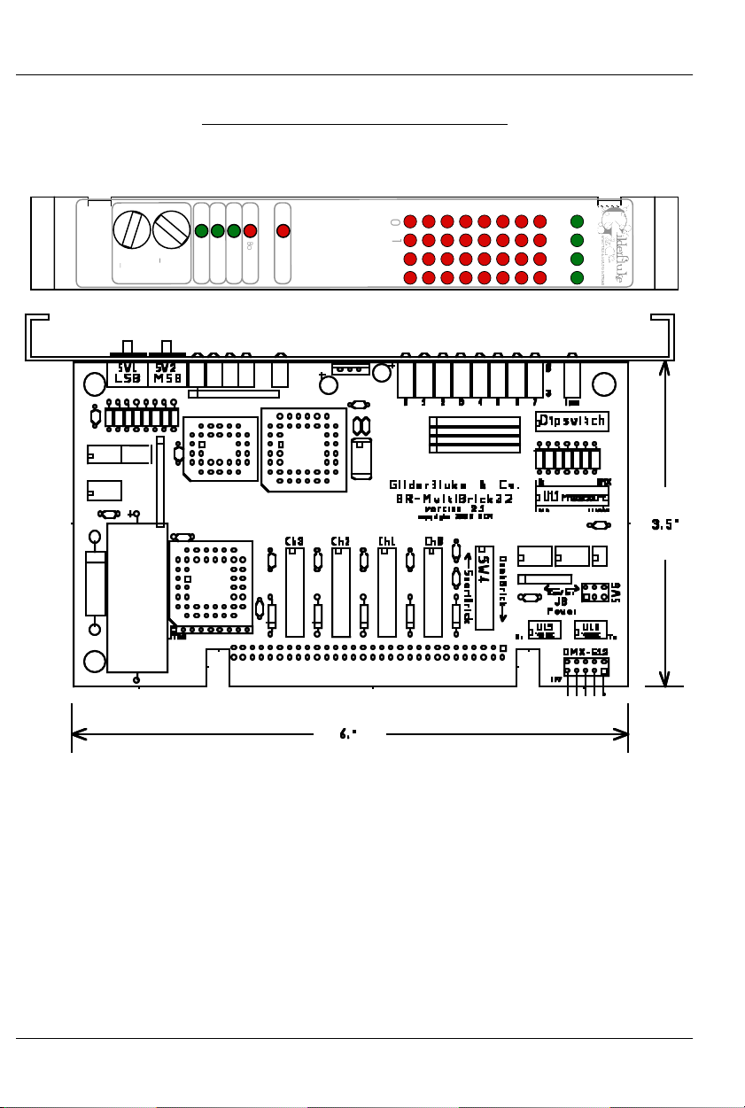
Board Error
DMX-
512
Brain Heart/
Running
Heartbeat
Addres
s
BR-Multi-
Brick32
Record
MSB
(
x0h)
0
1
2
3
4
5
6
7
Outputs
0
1
2
3
Fuse
s
LSB
(0
xh)
C
4
0
8
E
2
6
A
D
F
1
B
9
7
5
3
C
4
0
8
E
2
6
A
D
F
1
B
9
7
5
3
0
1
2
3
GILDERFLUKE & CO .• 205 SOUTH FLOWER STREET • BURBANK , CALIFORNIA 91502 • 818/840-9484 • 800/776-5972 • FAX 818/840-9485
E
AST COAST /FLORIDA O FFICE • 7041 GRAND NATIONAL DRIVE • SUITE 128d • ORLANDO , FL. 32819 • 407/354-5954 • FAX 407/354-5955
BR-MultiBrick32 Indicators
There are only a small number of connections, indicators, and configuration dip-
switches on each BR-MultiBrick32.
There are five Status LEDs on the BR-MultiBrick32:
1) Heartbeat: The ‘heartbeat’ will always flash so that you can see
that the BR-MultiBrick32 is alive. If this LED doesn’t flash at least
twice per second, you should power down the BR-MultiBrick32
and check the power supply and connections to the BRMultiBrick32. If this output ever stops flashing, a special circuit on
the BR-MultiBrick32 will reset and restart the microcontroller in less
than a second.
2) 'Smart' Brick Heart/Brick Running: Depending on the mode of
operation the BR-MultiBrick32 is in, this LED has several different
functions:
4 of 36
Page 11

GILDERFLUKE & CO .• 205 SOUTH FLOWER STREET • BURBANK , CALIFORNIA 91502 • 818/840-9484 • 800/776-5972 • FAX 818/840-9485
E
AST COAST /FLORIDA O FFICE • 7041 GRAND NATIONAL DRIVE • SUITE 128d • ORLANDO , FL. 32819 • 407/354-5954 • FAX 407/354-5955
a) When operating as a 'Smart' Brick: This LED will display the
'Smart' Brick Brain’s heartbeat. This is transmitted from the 'Smart' Brick Brain through the 'Smart' Brick Network that interconnects all of the 'Smart' Bricks. If this LED is not flashing,
then you need to check your 'Smart' Brick Network connections or your 'Smart' Brick Brain.
b) When operating as a 'Dumb' Brick: This LED will be ON
whenever a show is running. It will be off when no shows are
running. This output is also sent out the ‘Yellow’ status output
on the ‘J8’ connection on the backplane.
c) When receiving data download for permanent storage in
Flash memory (Revision 1.nn Cards Only): This LED will
flash to show that data is being received.
3) DMX-512: This LED will light to show you that the BR-MultiBrick32 is
receiving realtime updates through either the DMX-512 or RS-422
serial ports.
4) Board Error: This LED will flash to show you that the BR-MultiBrick32
has sensed one of the following errors:
a) Just booted: Lights for a short period each time the BR-
MultiBrick32’s microcontroller starts up.
b) 'Smart' Brick Network Error: Flashes if an error is received
in a 'Smart' Brick Network packet from the 'Smart' Brick Brain.
c) Realtime DMX-512 Update Error: The optional checksum in
the DMX-512 realtime update didn’t agree with the data received.
d) Realtime Serial Update Error: The checksum in the RS-422
serial port realtime update didn’t agree with the data received.
e) Download Error: There was an error in the data being
downloaded to the BR-MultiBrick32.
f) Download Timeout: If the data being downloaded to the
BR-MultiBrick32 stops mid-stream, this LED will flash as the BRMultiBrick32 returns itself to normal operating mode.
g) Data Verification Failure: If you ask the BR-MultiBrick32 to
verify the data in its flash memory, and it finds an error, it
will flash this LED as well as displaying an error message on
your computer screen.
h) Memory locked: If you try to clear the flash memory or
5 of 36
Page 12

GILDERFLUKE & CO .• 205 SOUTH FLOWER STREET • BURBANK , CALIFORNIA 91502 • 818/840-9484 • 800/776-5972 • FAX 818/840-9485
E
AST COAST /FLORIDA O FFICE • 7041 GRAND NATIONAL DRIVE • SUITE 128d • ORLANDO , FL. 32819 • 407/354-5954 • FAX 407/354-5955
send a show to the BR-MultiBrick32 while the Write Protect
switch is in the ‘locked’ position.
5) Record: This LED is turned on whenever a revision 1.nn BRMultiBrick32 has had its ‘Record Enable’ button pushed. It indicates that the BR-MultiBrick32 has had its DMX-512 and 'Smart'
Brick Network ports disabled and the RS-422 port enabled. This LED
must be ON to talk to the BR-MultiBrick32 through the RS-422 serial port.
In revision 2.00 and later BR-MultiBrick32 hardware there is no
‘Record Enable’ button. The RS-422 port, BrickNet, and DMX-512
ports are always available. This LED will light whenever the card is
being configured and flash when it is receiving an AutoDownload
file.
6) Output LEDs (Revision 2.00 and Later Cards Only): These thirtytwo LEDs show the current status of the thirty-two digital outputs. If
a LED is lit, then that output is ‘ON’. Because the outputs of a BRMultiBrick32 are ‘Open Collector, Switch To Ground’, you can
ground out any output pin, and the appropriate LED will light. This
can be useful when diagnosing output wiring problems. If you are
commanding ‘on’ an output and you don’t see a LED, then the
output is probably drawing too much current and the output is
‘self protecting’. Disconnect the load and see if the LED now
lights. If it does, then it definitely is an overload problem. If it does
not, then try turning ‘on’ some of the other outputs. if they light
OK, then the output driver might be damaged. If they do not,
then verify your addressing and retest.
7) Fuses (Revision 2.00 and Later Cards Only): The thirty-two outputs of the BR-MultiBrick32 are divided into four, eight-bit ‘channels’. Each of these channels is fused for approximately one Amp
of continuous current. These four LEDs light to show if the four
fuses are OK. If any are out, then a short circuit (or too heavy of a
load) is dragging the outputs down and causing the fuse to open.
The fuses are actually ‘PTC fuses’, which act more like circuit
breakers. Once the overload is removed, they reset.
6 of 36
Page 13

GILDERFLUKE & CO .• 205 SOUTH FLOWER STREET • BURBANK , CALIFORNIA 91502 • 818/840-9484 • 800/776-5972 • FAX 818/840-9485
E
AST COAST /FLORIDA O FFICE • 7041 GRAND NATIONAL DRIVE • SUITE 128d • ORLANDO , FL. 32819 • 407/354-5954 • FAX 407/354-5955
BR-MultiBrick32 Connections
RS-422 Serial Port (Revision 1.nn Cards Only): This is used to config-
ure the BR-MultiBrick32. It is compatible with all of the RS-422 Serial Ports used on Gilderfluke & Company products.
As a convenience, the four active lines on this connector are
bussed to the backplane of the card cage. This allows you to
communicate to a whole card cage full of BR-MultiBrick32, BSANAs, 'Smart' Brick Brains, Electronic FeedBack (EFB) 'Smart' Bricks
and other cards through the connector on any single card. They
just need to be set to different addresses. If desired, permanent
connections can be made on the back of a card cage.
Revision 2.00 and later BR-MultiBrick32 cards have only the
backplane serial port connections.
The serial data signals from the 1.nn revision BR-MultiBrick32s
are brought out on a six position RJ-12 (six position, six conductor
modular telephone style connector). Facing the end of the cable
with the release latch upwards, its pin out is as follows:
COLOR SIGNAL NAME:
LEFT #1 white Signal Ground
#2 black - Serial data out from card
#3 red + Serial data out from card
#4 green - Serial data in to card
#5 yellow + Serial data in to card
RIGHT #6 blue Signal Ground
PC and Compatible Connections: If you are only talking to a
single BR-MultiBrick32 and your wire length is short, you may be
able to simply cross wire the RS-232 serial port on your PC to talk
to the BR-MultiBrick32. This does not work on all PCs, as some
don’t swing their RS-232 outputs as far as they should. If it does
not work with your PC, you may need to get a RS-232 to RS-422
converter (like our 232conv-09) to talk to the BR-MultiBrick32. To
cross wire the RS-422 / RS-485 signals from the BR-MultiBrick32 to
the RS-232 serial port of an IBM compatible, cross connect the
signals as follows:
DB-25 DE-9 Signal Signal from/to BR-MultiBrick32
2 3 DATA OUT - Serial data into card (#4 green)
3 2 DATA IN - Serial data out from card (#2 black)
7 5 GROUND Signal Ground (#1 white or #6 blue)
Apple Macintosh Connections: Apple Macintosh computers
7 of 36
Page 14

t
GILDERFLUKE & CO .• 205 SOUTH FLOWER STREET • BURBANK , CALIFORNIA 91502 • 818/840-9484 • 800/776-5972 • FAX 818/840-9485
E
AST COAST /FLORIDA O FFICE • 7041 GRAND NATIONAL DRIVE • SUITE 128d • ORLANDO , FL. 32819 • 407/354-5954 • FAX 407/354-5955
have true RS-422 serial ports built in. To connect to the BRMultiBrick32, the pin out is as follows (view is of male connector
facing the end of the cable):
o + serial data in to card (#5 yellow)
to - serial data in to card (#4 green)
signal ground (#1 blue or #6 white)
678
345
12
from + serial data out from card (#3 red)
from - serial data out from card (#2 black)
The BR-MultiBrick32 expects to see the serial data in the follow-
ing format:
ONE START BIT
EIGHT DATA BITS
ONE STOP BIT
Unlike many of the products manufactured by Gilderfluke &
Company, the 1.nn revision BR-MultiBrick32s respond only to the
commands to enter the configuration mode, download/upload
configuration and status inquiries. It will ignore all other commands, which allows it to share the same RS-422 serial line with
additional BR-MultiBrick32s, BS-ANAs, Digital Audio Repeaters, 'Smart' Brick Brains and other serially controlled devices. The only requirement is that each unit be addressed to a different location.
Starting with revision 2.00 BR-MultiBrick32s, the RS-422 serial
port is available full-time. As a multidrop Serial network, it can be
used to select and play shows, check the status of a card, or
AutoDownload shows from any point on the network. Since it is
100% compatible with the RS-422 serial ports on all other Gilderfluke & Company equipment, a multidrop network can consist of
up to 256 other Gilderfluke & Company devices.
Since this is probably the most widely used of industrial data
networks, a myriad of other pieces of equipment are available
which will also work with the RS-422 serial buss. A typical application is to use a touch screen operator interface to access and
play shows. These generally use a user definable graphical interface. You pretty much draw a button, and then attach a string to
it. When this on-screen button is pushed, this string is sent out to
control the downstream equipment.
DMX-512 Data In/Out: Five pin MiniDIN connector (revision 1.nn
cards only). Revision 2.0 and later BR-MultiBrick32 have only the
8 of 36
Page 15

GILDERFLUKE & CO .• 205 SOUTH FLOWER STREET • BURBANK , CALIFORNIA 91502 • 818/840-9484 • 800/776-5972 • FAX 818/840-9485
E
AST COAST /FLORIDA O FFICE • 7041 GRAND NATIONAL DRIVE • SUITE 128d • ORLANDO , FL. 32819 • 407/354-5954 • FAX 407/354-5955
ten pin header for DMX-512 input and output through the backplane.
The BR-MultiBrick32 will stop listening to the 'Smart' Brick network whenever there is a DMX-512 signal present on this input.
The DMX-512 data lines on this connector will be attached to the
backplane DMX-512 header. This allows the DMX-512 signals to
be bussed between cards within a card cage.
The DMX-512 standard was developed by the United States Institute for Theatrical Technology (USITT) for a high speed (250
KBaud) asynchronous serial data link. Although it was originally designed for controlling light dimmers, it is now supported by hundreds of suppliers throughout the world for controlling all kinds of
theatrical equipment.
Even though the DMX-512 standard calls for 512 channels of
data, the DMX transmission from PC•MACs is limited to 256 eightbit wide channels. You can address your DMX-512 compatible
output devices to respond to any address between 0 and 255.
Addresses above the 256th are used in PC•MACs for transmitting
a checksum. The BR-MultiBrick32 can use this to verify that the
data received from PC•MACs has no transmission errors in it. If
you address a light dimmer or other DMX-512 device to addresses
256 or 257, you will see this verification data displayed as a flickering pattern. Note that at frame rates higher than forty FPS, not
all 256 channels can be transmitted through the DMX-512 output.
The DMX-512 standard calls out a 5 pin XLR connector for all
cabling. Unfortunately these connectors won't fit on a 1” wide
card. For this reason we chose a 5 pin MiniDIN connector for this
signal. the pinout is as follows:
MiniDIN pin # SIGNAL
1
1 Signal Common (shield)
2 Dimmer Drive compliment (Rx Data -)
3 Dimmer Drive True (Rx Data +)
4 Data In True (Tx Data +)
5 Data In compliment (Tx Data -)
Facing the end of the male end of a cable, the pins are located as shown:
1
Don't blame us for these names. These are directly from the USITT.
9 of 36
Page 16

GILDERFLUKE & CO .• 205 SOUTH FLOWER STREET • BURBANK , CALIFORNIA 91502 • 818/840-9484 • 800/776-5972 • FAX 818/840-9485
E
AST COAST /FLORIDA O FFICE • 7041 GRAND NATIONAL DRIVE • SUITE 128d • ORLANDO , FL. 32819 • 407/354-5954 • FAX 407/354-5955
Data In True (Tx Data +)
Dimmer Drive Compliment (Rx Data -)
signal ground
Data from a PC•MACs should be fed into pins #2 (-RxD) and
#3 (+RxD). The shield should be connected to pin #1.
‘Smart’ Brick Network: If Switch #4 is in the ‘Smart’ Brick position, the
BR-MultiBrick32 will be operating as a ‘Smart’ Brick. The ‘Smart’ Brick
Network normally found on a ‘Smart’ Brick is brought out on the
edge connector. When plugged into any Gilderfluke & Co. Brick
card cage, this will be brought out on a RJ-12 connector on the
card cage. A card cage should not have both ‘Smart’ and ‘Dumb’
Bricks in the same card cage. They share the same pins on the
edge connector and backplane. Damage may result if both are
installed in the same card cage.
The ‘Smart’ Brick Network signals to the BR-MultiBrick32 are
brought in through a six position RJ-12 (six position, six conductor
modular telephone style connector) on the card cage. Facing
the end of the cable with the release latch upwards, its pin out is
as follows:
COLOR SIGNAL NAME:
LEFT #1 white Smart Brick Net Data +
#2 black Smart Brick Net Data -
#3 red Smart Brick Net Clock +
#4 green Smart Brick Net Clock #5 yellow Smart Brick Net Strobe +
RIGHT #6 blue Smart Brick Net Strobe -
‘J8’ Inputs: If Switch #4 is in the ‘Dumb’ Brick position, the BR-
MultiBrick32 will be operating as a ‘Dumb’ Brick. The trigger inputs
and status output normally found on a ‘Dumb’ Brick are brought
out on the edge connector. When plugged into any Gilderfluke &
Co. Brick card cage, this will be brought out on a RJ-12 connector on the card cage. A card cage should not have both ‘Smart’
and ‘Dumb’ Bricks in the same card cage. They share the same
pins on the edge connector and backplane. Damage may result
if both are installed in the same card cage.
These are four optically isolated digital inputs which can be
used to start, stop, pause or select specific show sequences to
4
23
5
1
Data In Compliment (Tx Data -)
Dimmer Drive True (Rx Data +)
10 of 36
Page 17

GILDERFLUKE & CO .• 205 SOUTH FLOWER STREET • BURBANK , CALIFORNIA 91502 • 818/840-9484 • 800/776-5972 • FAX 818/840-9485
E
AST COAST /FLORIDA O FFICE • 7041 GRAND NATIONAL DRIVE • SUITE 128d • ORLANDO , FL. 32819 • 407/354-5954 • FAX 407/354-5955
play. Facing the end of the wire, with the latch upwards, the
pinout of a standard ‘J8’ cable is as follows.
WHITE #1 (Input 'D')
BLACK #2 (common)
RED #3 (Input 'B')
GREEN #4 (Input 'A')
YELLOW #5 (status out)
BLUE #6 (Input 'C')
LED
2.2K-4.7k
J8 with Sw8 set for INTERNAL power
Any event can be triggered on either the ‘closing’ or ‘opening’
edge of any input. A ‘closing’ is when you apply a voltage to an
input. An ‘opening’ is when that voltage is removed. The inputs
can be triggered on any voltage from 12 to 24 VDC. If you don’t
have an external source of power for these two inputs, you can
‘steal’ some juice from the BR-MultiBrick32’s power supply connections by putting the ‘J8 Power’ switch in the ‘Internal’ position.
Power Supply: The last ten contacts of the BR-MultiBrick32’s edge
connector are used for the power supply connections. The BRMultiBrick32 can be run from any supply voltage from 9-24 VDC.
The outputs are powered from this supply connection as well. If
you are driving 24 VDC loads, then run the BR-MultiBrick32 on 24
VDC. If your loads require 12 VDC, then run the BR-MultiBrick32
on 12 VDC.
This input is protected from reversed polarity. An idle BRMultiBrick32 draws only about 200 milliamperes. The loads which
the BR-MultiBrick32 is controlling will usually draw far more current
than the BR-MultiBrick32 itself.
Digital Outputs: Each BR-MultiBrick32 has thirty-two outputs
(hence, the name). These are just like the standard outputs used
on all Gilderfluke & Company Show Control Systems. Card cages
to hold the BR-MultiBrick32s are available with screw terminals or
ribbon cable connections.
The Output connections for all Gilderfluke & Company Show
Control Systems are through ‘J-6’ output cables. These are forty
wire ribbon cables which are made up of four identical eight-bit
wide ‘channels’. A J-6 cable is often split up into four individual
channels. Each ‘1/4 J-6’ ribbon cable is made up of ten wires,
WHITE #1 (Input 'D')
BLACK #2 (common)
RED #3 (Input 'B')
GREEN #4 (Input 'A')
YELLOW #5 (status out)
BLUE #6 (Input C')
J8 with Sw8 set for
+ 12 to 24 VDC SUPPLY
+
LED
2.2K-4.7k
EXTERNAL power
11 of 36
Page 18

GILDERFLUKE & CO .• 205 SOUTH FLOWER STREET • BURBANK , CALIFORNIA 91502 • 818/840-9484 • 800/776-5972 • FAX 818/840-9485
E
AST COAST /FLORIDA O FFICE • 7041 GRAND NATIONAL DRIVE • SUITE 128d • ORLANDO , FL. 32819 • 407/354-5954 • FAX 407/354-5955
and can be used to control eight individual ‘digital’ (off/on) devices, or one eight-bit wide ‘analog’ device. Each group of ten
wires also includes a common power supply and ground wire.
To simplify wiring to any Gilderfluke animation system, the
connectors used on the 1/4 J-6 cables are what are called ‘insulation displacement’ (IDS) connectors. These simply snap on to an
entire cable, automatically ‘displacing’ the wire insulation and
making contact with the wires within. This means that an entire
ten wire cable can be terminated in seconds. All connectors are
polarized, to keep them from being plugged in backwards. Although there are tools made specifically for installing these connectors, the tool we find works best is a small bench vise.
Each J-6 cable is arranged in the following order:
wire number color wire function
1 brown circuit ground
2 red channel 0 data bit 7
3 orange channel 0 data bit 6
4 yellow channel 0 data bit 5
5 green channel 0 data bit 4
6 blue channel 0 data bit 3
7 violet channel 0 data bit 2
8 gray channel 0 data bit 1
9 white channel 0 data bit 0
10 black + VDC unregulated power supply
11 brown circuit ground
12 red channel 1 data bit 7
13 orange channel 1 data bit 6
14 yellow channel 1 data bit 5
15 green channel 1 data bit 4
16 blue channel 1 data bit 3
17 violet channel 1 data bit 2
18 gray channel 1 data bit 1
19 white channel 1 data bit 0
20 black + VDC unregulated power supply
21 brown circuit ground
22 red channel 2 data bit 7
23 orange channel 2 data bit 6
24 yellow channel 2 data bit 5
25 green channel 2 data bit 4
26 blue channel 2 data bit 3
27 violet channel 2 data bit 2
12 of 36
Page 19

k
GILDERFLUKE & CO .• 205 SOUTH FLOWER STREET • BURBANK , CALIFORNIA 91502 • 818/840-9484 • 800/776-5972 • FAX 818/840-9485
E
AST COAST /FLORIDA O FFICE • 7041 GRAND NATIONAL DRIVE • SUITE 128d • ORLANDO , FL. 32819 • 407/354-5954 • FAX 407/354-5955
28 gray channel 2 data bit 1
29 white channel 2 data bit 0
30 black + VDC unregulated power supply
31 brown circuit ground
32 red channel 3 data bit 7
33 orange channel 3 data bit 6
34 yellow channel 3 data bit 5
35 green channel 3 data bit 4
36 blue channel 3 data bit 3
37 violet channel 3 data bit 2
38 gray channel 3 data bit 1
39 white channel 3 data bit 0
40 black + VDC unregulated power supply
Any eight digital devices or one eight-bit analog device can
be connected to any 1/4 J-6 cable as shown. The LED between
the ground (pin #1 brown) wire and supply (pin #10 black) wire
acts as an indicator that is lit if the fuse for that channel is OK.
All outputs are open collector switches to ground. Flyback
diodes are included in the outputs for driving inductive loads.
Power is supplied through a diode and a solid state circuit breaker
to the common pin(s) on the connector. A safe level of current is
150 milliamperes simultaneously on each output. This is sufficient
to drive most small relays, valves and other similar loads directly. If
fewer than eight outputs are on at one time, then the outputs are
rated as follows.
fuse
flybac
supply supply
diode
typical output
typical input
The supply line for each 1/4 J-6 is PTC fused for 1 amp. You
should treat each 1/4 J-6 as an individual, and not cross the outputs or supply lines from one channel to the lines from any other
13 of 36
Page 20

O
%
y
GILDERFLUKE & CO .• 205 SOUTH FLOWER STREET • BURBANK , CALIFORNIA 91502 • 818/840-9484 • 800/776-5972 • FAX 818/840-9485
E
AST COAST /FLORIDA O FFICE • 7041 GRAND NATIONAL DRIVE • SUITE 128d • ORLANDO , FL. 32819 • 407/354-5954 • FAX 407/354-5955
channel. Doing this won’t cause any damage, but can reduce
the protection for the outputs that the fuses normally provide.
The current Output Capacity of each output is as shown in
the following chart:
Peak Collector Current as a function
600ma.
500ma.
400ma.
of Output Duty Cycle
2
300ma.
200ma.
Allowable Peak Collector Current @ 70ºC
100ma.
4
5
6
7
8
Number of outputs
conducting
simultaneousl
10% 20% 30% 40% 50% 60% 70% 80% 90%
utput Duty Cycle
Since it is unusual to have more than 50% of the outputs on
at any one time, you can usually assume the system has a 250
ma output current capacity. If you are going to be turning on lots
of heavy loads at the same time, you should derate this to 150
ma.. This is sufficient to drive the majority of loads which will be directly connected to the outputs of the animation system. If additional current capacity is needed, or if you need to drive higher
voltage loads, you can connect relays as needed to the outputs
of the animation system. Coincidentally, boards for doing this are
available from Gilderfluke & Company. These include:
DPDT relay board: A set of eight electromechanical relays with
double pole/double throw contacts rated at 5 amps each.
Reed relay board: A set of eight small electromechanical relays
with normally open contacts rated at 150 ma each.
I/O module: A set of eight small solid state relays with normally
open contacts rated at 3.5 amps each (alternating current
100
14 of 36
Page 21

GILDERFLUKE & CO .• 205 SOUTH FLOWER STREET • BURBANK , CALIFORNIA 91502 • 818/840-9484 • 800/776-5972 • FAX 818/840-9485
E
AST COAST /FLORIDA O FFICE • 7041 GRAND NATIONAL DRIVE • SUITE 128d • ORLANDO , FL. 32819 • 407/354-5954 • FAX 407/354-5955
and direct current relays available).
Solid State Relay Fanning Strip: For connecting up to eight
popular ‘hockey puck’ style relays to a 1/4 J-6 output cable.
These are available with capacities of up to 75 amps each.
15 of 36
Page 22

GILDERFLUKE & CO .• 205 SOUTH FLOWER STREET • BURBANK , CALIFORNIA 91502 • 818/840-9484 • 800/776-5972 • FAX 818/840-9485
E
AST COAST /FLORIDA O FFICE • 7041 GRAND NATIONAL DRIVE • SUITE 128d • ORLANDO , FL. 32819 • 407/354-5954 • FAX 407/354-5955
Edge Connector: All of the connections to and from BR-MultiBrick32
Cards are available on the 60 position edge connector. You can
use an Insulation Displacement Edge (IDE) connector if you aren’t
going to be using one of our card cages:
output wire # Edge pin #color wire function
J8 Black (common) 1 brown J8 Common (black)/'Smart' Brick Net Data-
J8 White (Reset) 2 red J8 ‘D’ (white) input/'Smart' Brick Net Data +
J8 Red (Stop) 3 orange J8 ‘B’ (red) input/'Smart' Brick Net Clk +
Serial Port red #3 4 yellow TxD + out from BR-MultiBrick32
J8 Green (Start) 5 green J8 ‘A’ (green) input/'Smart' Brick Net Clk -
Serial Port Black #2 6 blue TxD - out from BR-MultiBrick32
J8 Yellow (Status Out) 7 violet J8 Status (yellow) out/'Smart' Brick Strobe +
Serial Port Yellow #5 8 gray Rx + in to BR-MultiBrick32
J8 Blue (Clock/Dbl. Show) 9 white J8 ‘C’ (blue) input/'Smart' Brick Net Strobe -
Serial Port green #4 10 black Rx -in to BR-MultiBrick32
#1 11 brown J6 out channel 0 Ground
#2 12 red J6 out channel 0 bit 7
#3 13 orange J6 out channel 0 bit 6
#4 14 yellow J6 out channel 0 bit 5
#5 15 green J6 out channel 0 bit 4
#6 16 blue J6 out channel 0 bit 3
#7 17 violet J6 out channel 0 bit 2
#8 18 gray J6 out channel 0 bit 1
#9 19 white J6 out channel 0 bit 0
#10 2 0 black J6 out channel 0 + Supply
#11 21 brown J6 out channel 1 Ground
#12 22 red J6 out channel 1 bit 7
#13 23 orange J6 out channel 1 bit 6
#14 24 yellow J6 out channel 1 bit 5
#15 25 green J6 out channel 1 bit 4
#16 26 blue J6 out channel 1 bit 3
#17 27 violet J6 out channel 1 bit 2
#18 28 gray J6 out channel 1 bit 1
#19 29 white J6 out channel 1 bit 0
#20 3 0 black J6 out channel 1 + Supply
#21 31 brown J6 out channel 2 Ground
#22 32 red J6 out channel 2 bit 7
#23 33 orange J6 out channel 2 bit 6
#24 34 yellow J6 out channel 2 bit 5
16 of 36
Page 23

GILDERFLUKE & CO .• 205 SOUTH FLOWER STREET • BURBANK , CALIFORNIA 91502 • 818/840-9484 • 800/776-5972 • FAX 818/840-9485
E
AST COAST /FLORIDA O FFICE • 7041 GRAND NATIONAL DRIVE • SUITE 128d • ORLANDO , FL. 32819 • 407/354-5954 • FAX 407/354-5955
#25 35 green J6 out channel 2 bit 4
#26 36 blue J6 out channel 2 bit 3
#27 37 violet J6 out channel 2 bit 2
#28 38 gray J6 out channel 2 bit 1
#29 39 white J6 out channel 2 bit 0
#30 4 0 black J6 out channel 2 + Supply
#31 41 brown J6 out channel 3 Ground
#32 42 red J6 out channel 3 bit 7
#33 43 orange J6 out channel 3 bit 6
#34 44 yellow J6 out channel 3 bit 5
#35 45 green J6 out channel 3 bit 4
#36 46 blue J6 out channel 3 bit 3
#37 47 violet J6 out channel 3 bit 2
#38 48 gray J6 out channel 3 bit 1
#39 49 white J6 out channel 3 bit 0
#40 5 0 black J6 out channel 3 + Supply
black 51 brown power supply ground
black 52 red power supply ground
black 53 orange power supply ground
black 54 yellow power supply ground
black 55 green power supply ground
red 56 blue + power supply input
red 57 violet + power supply input
red 58 gray + power supply input
red 59 white + power supply input
red 6 0 black + power supply input
17 of 36
Page 24

GILDERFLUKE & CO .• 205 SOUTH FLOWER STREET • BURBANK , CALIFORNIA 91502 • 818/840-9484 • 800/776-5972 • FAX 818/840-9485
E
AST COAST /FLORIDA O FFICE • 7041 GRAND NATIONAL DRIVE • SUITE 128d • ORLANDO , FL. 32819 • 407/354-5954 • FAX 407/354-5955
Preparing Animation Data for AutoDownloads
The Eprom Memories used for the original 'Brick' products manufactured
by Gilderfluke & Company each contained one channel (eight-bits) worth
of data. Later products used Eproms which contained several channels
each. The Flash Memories used on the BR-MultiBrick32, BR-ANA, BR-EFB and
BR-SmartMedia use a MultiChannel format with a complex header to allow
them to be AutoDownloaded from PC•MACs.The following instructions apply
to all of cards that use AutoDownload files.
After you have finished programming your show(s), files are AutoDownloaded from PC•MACs by:
1) Selecting the 'Save as AutoDownload...' command from the 'File'
pulldown.
2) Use the ‘Add’ button to select any additional show(s) you would
like to be saved into this AutoDownload file.
3) Use the ‘Promote’ and ‘Demote’ buttons to move selected show(s)
into the order you would like to save them in the Flash Memory.
4) Select the ‘first show’ and what will happen to the BR-MultiBrick32
on power up. If you will be operating the BR-MultiBrick32 as a 'Smart' Brick, then set the power up action to ‘wait’. If you have set
the BR-MultiBrick32 to ‘wait’ at power up, then the first frame of
the show you have selected will be output as soon as power is applied to the BR-MultiBrick32.
5) Set what will happen on each of the four ‘J8’ optoisolated inputs if
you will be operating the BR-MultiBrick32 as a 'Dumb' Brick. You
can ignore these settings if you will be running it as a 'Smart' Brick.
6) Select each show to be downloaded one at a time and set what
will happen at the end of each show and whether it can be
‘stepped on’ if you will be operating the BR-MultiBrick32 as a 'Dumb' Brick. You can ignore these settings if you will be running it as a
'Smart' Brick. When operating as a ‘Dumb’ Brick, any show which
can be stepped upon can be interrupted mid-show by a new
show start coming in. Any show which can not be stepped upon
will ignore all additional start commands while it is still playing.
7) Set the ‘Brick Serial Address’ to send the AutoDownload file to. This
is the serial address of the card you want it to be received by. All
other cards will ignore the data being sent to this one card. With
BR-MultiBrick32s, the address is usually the same as the ‘start’
channel set in the next step.
18 of 36
Page 25

GILDERFLUKE & CO .• 205 SOUTH FLOWER STREET • BURBANK , CALIFORNIA 91502 • 818/840-9484 • 800/776-5972 • FAX 818/840-9485
E
AST COAST /FLORIDA O FFICE • 7041 GRAND NATIONAL DRIVE • SUITE 128d • ORLANDO , FL. 32819 • 407/354-5954 • FAX 407/354-5955
8) Set the 'first channel' and 'last channel' boxes to set the number
channels you want to go into this AutoDownload file. A BRMultiBrick32 holds four channels worth of data. If this is the first (or
only) BR-MultiBrick32 in the system, the addresses are typically set
for ‘0’ to ‘3’.
9) The ‘Calculate Brick Start Frames’ checkbox must always be
checked.
10) The ‘Save Brick Starts’ checkbox should not be checked.
11) You can quickly test if the BR-MultiBrick32 is attached to the serial
port properly by hitting the ‘Reset MiniBrick’ button. Of course, this
will also erase any show data that was already in the BRMultiBrick32’s flash memory. PC•MACs will report if the Reset was
successful or not.
12) Press the ‘Build’ or ‘Download’ button to begin the saving process.
A ‘Build’ will just save the AutoDownload file to your disk, without
sending it to the BR-MultiBrick32. A ‘Download’ will save the file to
disk and send it to the BR-MultiBrick32. A standard file save dialog
will open. Double check the Directory location and name the file
as desired. (it defaults to the name of the first show in the list). You
can tell Windows to save the file to a different directory, if needed. PC•MACs will warn you if a file already exists in this location
with this same name. Hit OK (or change the name & hit OK if you
want to preserve the older file) to save the data to a file.
After doing an AutoDownload, if you press the ‘Report’ button, PC•MACs
will display the information about the AutoDownload file you just saved. This
information is also saved in a text file with the same name as the Flash
Memories, but with the extension of ‘.set’. You can open this file with any
text editor (like Notepad or Wordpad). The numbers shown for ‘Brick start’
and ‘Brick end’ are what you need to enter into the 'Smart' Brick Brain to set
the start and end of each show (If you will be running the BR-MultiBrick32 as
a 'Smart' Brick). The ‘Eprom Memory start’ and ‘Eprom Memory end’ are
the actual locations of the shows in the Flash Memory set. The number
shown for the ‘Eprom Memory End’ for the last show in this file set is the last
byte which will be saved into the Flash Memory. If your Flash Memory is
smaller than this number, you will need to use external show data storage
(such as a BR-SmartMedia) or have your BR-MultiBrick32 retrofitted with a
larger Flash memory. Contact Gilderfluke & Co. if you need to have your
flash memory expanded.
The AutoDownload file that PC•MACs automatically generates will have
the extension of filename.Ann. The 'A' in the extension flags it as a
19 of 36
Page 26

GILDERFLUKE & CO .• 205 SOUTH FLOWER STREET • BURBANK , CALIFORNIA 91502 • 818/840-9484 • 800/776-5972 • FAX 818/840-9485
E
AST COAST /FLORIDA O FFICE • 7041 GRAND NATIONAL DRIVE • SUITE 128d • ORLANDO , FL. 32819 • 407/354-5954 • FAX 407/354-5955
'AutoDownload' file. The 'nn' is the HEXadecimal address of the first channel
in the AutoDownload set. If you are AutoDownloading to a number of different cards, you can use the same name for all of them without fear of overwriting the others since they will automatically have different ‘extensions’.
This file can be sent to any other BR-MultiBrick32 at any time using a computer and a terminal program like terminal.exe or our GilderTerm. HyperTerm.exe will not work for this, because it randomly alters values above 128
in the AutoDownload file.
The address of the data sent out from Flash memory may be different
from what you saw when programming through the DMX-512 or serial
input. This is a question of the address selected for the BR-MultiBrick32 and
address range selected for the data when sending the AutoDownload file.
The BR-MultiBrick32 always uses the address saved in the AutoDownload file
for its outputs. This is normally what you want to do.
20 of 36
Page 27

GILDERFLUKE & CO .• 205 SOUTH FLOWER STREET • BURBANK , CALIFORNIA 91502 • 818/840-9484 • 800/776-5972 • FAX 818/840-9485
E
AST COAST /FLORIDA O FFICE • 7041 GRAND NATIONAL DRIVE • SUITE 128d • ORLANDO , FL. 32819 • 407/354-5954 • FAX 407/354-5955
BR-MultiBrick32 Serial Port Commands:
The BR-MultiBrick32 can be accessed through the serial port from any
computer running just about any modem or terminal program. The computer you are using doesn’t even need to have any PC•MACs software installed on it.
Most Gilderfluke & Co products can be controlled through their RS-422
Serial ports. Up to 256 different cards and devices can be attached to the
same serial lines, to form a complete RS-422 ‘multi Drop’ network. Anywhere
on this network you can attach operator panels to access and control it, or
you can use a telephone or Internet modem so that it can be accessed
from around the block or around the world. Commands can be addressed
to a single card on the network, or all of the cards simultaneously.
One of the easiest and most flexible types of operator interfaces for accessing the serial network are the many touch screen operator panels.
These are available from a number of different suppliers, and most of them
will easily attach right to our serial network. Most of these allow you to ‘draw’
whatever buttons and user interface icons on their screens (using a provided Windows program), attach ASCII strings to these ‘buttons’, and then
download the final configuration to the operator panel so the PC can be
taken away.
Typical modem programs you can use are Terminal.exe (which came
with Windows 3.1) and HyperTerm.exe (which comes later versions of Windows), or GilderTerm.
GilderTerm is available free from Gilderfluke & Co. for use with all of our
products. It can be downloaded from our web page, and is included on all
of our CD-ROMs. GilderTerm has been optimized for use with all Gilderfluke
& Company equipment. All of the commands are built in, and it will even
let you use your mouse to select commands.
To use the BR-MultiBrick32 with a terminal program, just configure it for
9600 baud, no parity, eight data bits, one stop bit and ‘xon/xoff’ handshaking. If you are using GilderTerm, all of the settings are fixed at the appropriate settings. All you will need to do is select the appropriate ‘COM’ port.
Echo Commands:
“a” [nn] (card address) Echo On:
“b” Echo Off:
The ‘Echo ON’ command will turn on a special mode that will
cause all of the other serial port commands to echo on the selected card. This used when you are setting up serial commands
21 of 36
Page 28

GILDERFLUKE & CO .• 205 SOUTH FLOWER STREET • BURBANK , CALIFORNIA 91502 • 818/840-9484 • 800/776-5972 • FAX 818/840-9485
E
AST COAST /FLORIDA O FFICE • 7041 GRAND NATIONAL DRIVE • SUITE 128d • ORLANDO , FL. 32819 • 407/354-5954 • FAX 407/354-5955
so you can verify all the commands you are issuing are being received correctly (the ‘echo’ responses are shown in
italics
):
If you send “a00”, the echo mode will be turned ON:
card 00h/__0, echo mode on
If you send “*03” to request a specific show:
card 00h/__0, requested show 03h/__3 CHEEBURG
If you send “t00” to start the requested show playing on a specific
card:
card 00h/__0, starting show 03h/__3 CHEEBURG
If you send “!00” to start a show looping on a specific card:
card 00h/__0, looping show 04h/__4 FRUTCAKE
If you send “u” to stop a show playing:
card 00h/__0, stopped show 05h/__5 IGETARND
If you send “u” to stop a card that is already stopped, it will give
you an error message:
card 00h/__0, error: not playing or looping 05h/__5 IGETARND
Similar error messages will be returned whenever you ask the card
to do something that it can not do at the current time.
The ‘Echo OFF’ command will turn off the echo mode on all
the cards in the system.
“i” [nn] (card address) Card Status:
When the BR-MultiBrick32 receives this command, it will re-
spond with the following information:
a) Gilderfluke & Company, product name, Firmware revision
number and copyright.
b) Card serial address and if the Flash is write protected.
c) Amount of Flash memory installed.
d) Whether or not the Flash memory is enabled for writing.
e) If it is operating as a 'Smart' Brick:
1) The frame number currently being accessed by the
'Smart' Brick Network.
f) If it is operating as a ‘Dumb’ Brick:
22 of 36
Page 29

GILDERFLUKE & CO .• 205 SOUTH FLOWER STREET • BURBANK , CALIFORNIA 91502 • 818/840-9484 • 800/776-5972 • FAX 818/840-9485
E
AST COAST /FLORIDA O FFICE • 7041 GRAND NATIONAL DRIVE • SUITE 128d • ORLANDO , FL. 32819 • 407/354-5954 • FAX 407/354-5955
1) Whether the card is running, stopped, looping or
paused.
2) The current status of the four optically isolated inputs.
g) Information on the currently loaded AutoDownload file:
1) AutoDownload file name (in DOS 8.3 format).
2) Number of channels in the AutoDownload file.
3) Number of shows in the AutoDownload file.
4) AutoDownload file Header information.
5) Individual show information with
a) Show number in the AutoDownload file.
b) The offset to the start of the show data.
c) How long the show is (in frames).
d) The show flag (which sets frame rate and step-
pability).
e) Which show is defined as ‘next’. If no specific
show number as entered, a ‘00’ means ‘whatever is next in list’.
f) The name of the show (in DOS 8.3 format).
The following shows a BR-MultiBrick32 information status response for a
card which is operating as a 'Smart' Brick:
Gilderfluke & Co. MultiBrick32
firmware revision 2.10
copyright 2002 DCM
Card addressed at 01h/__1
4 Mbits (512KBytes) memory installed
Writing to Flash is Enabled
Smart Brick @ frame 00D86h/___3462
AutoDownload FileName: TEST.A00
Number of channels: 04h/__4
Number of shows: 06h/__6
00 B0 A1 01 04 06 01 01 08 00 01 00 04 00 01 00 08 01 01 00 20 04 40 00
01h/__1 st:00000h/______0 len:0122Ah/___4650 fl:EDh nxt:01h/__1 KOKIMO.SHO
02h/__2 st:0122Ah/___4650 len:01374h/___4980 fl:CDh nxt:00h/__0 MARGVILL.SHO
03h/__3 st:0259Eh/___9630 len:01248h/___4680 fl:CDh nxt:00h/__0 CHEEBURG.SHO
04h/__4 st:037E6h/__14310 len:0122Ah/___4650 fl:CDh nxt:00h/__0 FRUTCAKE.SHO
05h/__5 st:04A10h/__18960 len:00EA6h/___3750 fl:CDh nxt:00h/__0 IGETARND.SHO
06h/__6 st:058B6h/__22710 len:00F96h/___3990 fl:CDh nxt:00h/__0 409.SHO
(Sample data: Your show data will differ from what is shown.)
The status screen is a snapshot image of the current status of
the BR-MultiBrick32. If you want to update the status information
displayed, you must hit the ‘Card Status’ command a second
time.
23 of 36
Page 30

GILDERFLUKE & CO .• 205 SOUTH FLOWER STREET • BURBANK , CALIFORNIA 91502 • 818/840-9484 • 800/776-5972 • FAX 818/840-9485
E
AST COAST /FLORIDA O FFICE • 7041 GRAND NATIONAL DRIVE • SUITE 128d • ORLANDO , FL. 32819 • 407/354-5954 • FAX 407/354-5955
The following shows a BR-MultiBrick32 information status re-
sponse for a card which is operating as a 'Dumb' Brick:
Gilderfluke & Co. MultiBrick32
firmware revision 2.10
copyright 2002 DCM
Card addressed at 00h/__0
4 Mbits (512KBytes) memory installed
Writing to Flash is Enabled
Input A/Green now Open
Input B/Red now Open
Input C/Blue now Open
Input D/White now Open
Dumb Brick show 01h/__1 KOKIMO looping @ frame 00F27h/___3879
AutoDownload FileName: TEST.A00
Number of channels: 04h/__4
Number of shows: 06h/__6
00 B0 A1 01 04 06 01 01 08 00 01 00 04 00 01 00 08 01 01 00 20 04 40 00
01h/__1 st:00000h/______0 len:0122Ah/___4650 fl:EDh nxt:01h/__1 KOKIMO.SHO
02h/__2 st:0122Ah/___4650 len:01374h/___4980 fl:CDh nxt:00h/__0 MARGVILL.SHO
03h/__3 st:0259Eh/___9630 len:01248h/___4680 fl:CDh nxt:00h/__0 CHEEBURG.SHO
04h/__4 st:037E6h/__14310 len:0122Ah/___4650 fl:CDh nxt:00h/__0 FRUTCAKE.SHO
05h/__5 st:04A10h/__18960 len:00EA6h/___3750 fl:CDh nxt:00h/__0 IGETARND.SHO
06h/__6 st:058B6h/__22710 len:00F96h/___3990 fl:CDh nxt:00h/__0 409.SHO
(Sample data: Your show data will differ from what is shown.)
“j5AA5” [nn] (card address) Card Reset:
This command will erase the 'Flash' memory on the BR-
MultiBrick32. The BR-MultiBrick32 will also determine the type and
quantity of memory chips installed and report this and the software revision number when it accepts this command.
Start Commands:
“t” [nn] (card address) Start Track:
“u” Start Global:
These commands are available ONLY on 2.0 or later revision
cards which are being operated as ‘Dumb’ Bricks. If your system
has a 'Smart' Brick Brain, then these commands should be addressed to the 'Brain'.
These commands start the animation playing on the BR-
MultiBrick32(s) addressed by the command. The shows will always
start from the beginning. If an addressed BR-MultiBrick32 is looping
shows, it will have the ‘LOOPING SHOWS’ flag reset.
If the BR-MultiBrick32 receives a start command after it has re-
ceived a request for a specific show, it will play that show. Other-
24 of 36
Page 31

GILDERFLUKE & CO .• 205 SOUTH FLOWER STREET • BURBANK , CALIFORNIA 91502 • 818/840-9484 • 800/776-5972 • FAX 818/840-9485
E
AST COAST /FLORIDA O FFICE • 7041 GRAND NATIONAL DRIVE • SUITE 128d • ORLANDO , FL. 32819 • 407/354-5954 • FAX 407/354-5955
wise it will play the show that has been set as the ‘next’ show for
the show which is currently playing (or most recently played show
if it is not currently playing). If this is the first show played after a
BR-MultiBrick32 is reset, it will play the show which has been set as
the ‘first’ show during the AutoDownload. Requests for specific
shows can come only from the serial port.
When shows are downloaded to the BR-MultiBrick32, they can
can be set to ignore additional start commands while they are
playing. This allows individual shows to be ‘stepped’ upon or not. If
the BR-MultiBrick32 is already playing a show which has this option
set, it will ignore this command.
Stop Commands:
“x” [nn] (card address) Stop Track:
“y” Stop Global:
These commands are available ONLY on 2.0 or later revision
cards which are being operated as ‘Dumb’ Bricks. If your system
has a Smart Brick Brain, then these commands should be addressed to the 'Brain'.
These commands stop the selected BR-MultiBrick32(s) unconditionally. The stop takes place at the current frame being played.
Loop Commands:
“!” [nn] (card address) Loop Track:
““” Loop Global:
These commands are available ONLY on 2.0 or later revision
cards which are being operated as ‘Dumb’ Bricks. If your system
has a Smart Brick Brain, then these commands should be addressed to the 'Brain'.
These command acts much like the START commands, except
that they also set the ‘LOOPING SHOWS’ flag. With this flag set, it is
possible to set a sequence of shows playing in any order. Since
the ‘next’ show can be any show you ask for, one show can be
played over and over again, or you can set up a sequence of
shows which will be repeated until the BR-MultiBrick32 is told to
stop.
Stop at End Commands:
“%” [nn] (card address) Stop at End Track:
“&” Stop at End Global:
25 of 36
Page 32

GILDERFLUKE & CO .• 205 SOUTH FLOWER STREET • BURBANK , CALIFORNIA 91502 • 818/840-9484 • 800/776-5972 • FAX 818/840-9485
E
AST COAST /FLORIDA O FFICE • 7041 GRAND NATIONAL DRIVE • SUITE 128d • ORLANDO , FL. 32819 • 407/354-5954 • FAX 407/354-5955
These commands are available ONLY on 2.0 or later revision
cards which are being operated as ‘Dumb’ Bricks. If your system
has a Smart Brick Brain, then these commands should be addressed to the 'Brain'.
These commands reset the ‘LOOPING SHOWS’ flag in the se-
lected BR-MultiBrick32(s). What this does is to stop them playing
when the end of the current show is reached. These commands
are used when you want the shows to finish gracefully. The STOP
commands are used when you want to stop a show immediately.
Select Show Commands:
“)” [nn] (Card Address) [nn] (show#) Select Show Track:
“*” [nn] (show#) Select Show Global:
These commands are available ONLY on 2.0 or later revision
cards which are being operated as ‘Dumb’ Bricks. If your system
has a Smart Brick Brain, then these commands should be addressed to the 'Brain'.
Up to two hundred fifty-five different animated shows can be
stored on a single BR-MultiBrick32. These commands can be used
to select an individual show on the selected BR-MultiBrick32(s). Individual shows can be requested with a range of 01 to FFH. Once
a show is selected, it will be played on the next serial port START or
LOOP command.
If a show selection has been made inadvertently, it can be
cleared by sending a request for show number 00.
Show Pause Commands:
“<” [nn] (card address) Pause Show:
“>” [nn] (card address) Continue Show:
These commands are available ONLY on 2.0 or later revision
cards which are being operated as ‘Dumb’ Bricks. If your system
has a Smart Brick Brain, then these commands should be addressed to the 'Brain'.
Any show can be paused at any point during its playback. The
outputs are frozen at the levels they were at the instant the PAUSE
command is received.
The CONTINUE command will resume any show playing which
has previously been PAUSED.
26 of 36
Page 33

GILDERFLUKE & CO .• 205 SOUTH FLOWER STREET • BURBANK , CALIFORNIA 91502 • 818/840-9484 • 800/776-5972 • FAX 818/840-9485
E
AST COAST /FLORIDA O FFICE • 7041 GRAND NATIONAL DRIVE • SUITE 128d • ORLANDO , FL. 32819 • 407/354-5954 • FAX 407/354-5955
“sA5A5” [nn] (card address) AutoDownload:
This is the format of the file that the BR-MultiBrick32 will receive
and load into its 'Flash' memory.
An AutoDownload file is a binary file. Any AutoDownload file
that has previously been saved can be sent to a BR-MultiBrick32
by selecting the ‘send binary file’ on your modem program and
selecting the AutoDownload file for sending. You must be sure
that the modem program has not been set to ‘gobble’ any special characters (carriage returns, line feeds, etc.).
The Hyper Terminal program that comes with Windows ‘95 and
‘98 will not work for sending AutoDownloads. For some strange
reason it has been written to randomly change any binary value
that is larger than one hundred twenty-seven.
“~” RealTime Update:
This command sets the BR-MultiBrick32 into a mode where it
will update the outputs in realtime from the data received
through the serial port. The BR-MultiBrick32 uses this command to
update the outputs in real time.
The maximum frame rate supported by this function is thirty
frames per second. Any faster than this just won’t fit through the
PC’s serial port.
27 of 36
Page 34

GILDERFLUKE & CO .• 205 SOUTH FLOWER STREET • BURBANK , CALIFORNIA 91502 • 818/840-9484 • 800/776-5972 • FAX 818/840-9485
E
AST COAST /FLORIDA O FFICE • 7041 GRAND NATIONAL DRIVE • SUITE 128d • ORLANDO , FL. 32819 • 407/354-5954 • FAX 407/354-5955
BR-MultiBrick32 Hardware Configuration
BR-MultiBrick32 hardware configuration is done using a pair of address
switches, an eight position DipSwitch, and two slide switches:
a) Address: These two rotary switches on the front of the BR-
MultiBrick32 are used to set the RS-422 serial port address where
this card will be found. Normally, only one BR-MultiBrick32 card is
set to use any one address. If more than one card is set to the
same address, then only one card should have the ‘Record En-
able’ turned on at one time. BR-MultiBrick32 cards after revision
2.0 don’t have a ‘Record Enable’ switch, so shouldn’t be set to
the same addresses if they are on the same multidrop RS-422 serial port network.
The RS-422 serial address for the BR-MultiBrick32 is set using
Hexadecimal numbers on these switches. The first digit of the Hexadecimal address is set on the upper of the two switches. The
second digit of the hexadecimal address is set on the lower of the
two switches. If you are not sure how these translate from decimal
numbers, a chart at the end of every Gilderfluke & Company
manual will show you the equivalent numbers.
b) Record Enable (Revision 1.nn Cards Only): Pressing this switch
on pre- 2.0 revision cards turns off the DMX-512 and 'Smart' Brick
Network for this card and enables the RS-422 Serial Port. This must
be done to talk to the BR-MultiBrick32 through the serial port, or to
download shows to it from PC•MACs.
Pressing this button a second time or powering the BR-
MultiBrick32 down and then back up again will reset the card to
normal operation.
BR-MultiBrick32 cards after revision 2.00 don’t have a ‘Record
Enable’ switch. The RS-422 serial port, DMX-512 port and BrickNet
is active at all times for receiving AutoDownload files, RealTime
updates, and commands.
c) Eight Position Dipswitch: This is used as follows:
1) DMX-512 Forever!: When this switch is ON, the BR-
MultiBrick32 will only use the RealTime data received
through the DMX-512 port or RS-422 serial port for updating
its outputs. It will never use data from the onboard Flash
memory for output information. This is used if you will ONLY
be using the BR-MultiBrick32 as a DMX-512 (or serially) controlled card.
28 of 36
Page 35

GILDERFLUKE & CO .• 205 SOUTH FLOWER STREET • BURBANK , CALIFORNIA 91502 • 818/840-9484 • 800/776-5972 • FAX 818/840-9485
E
AST COAST /FLORIDA O FFICE • 7041 GRAND NATIONAL DRIVE • SUITE 128d • ORLANDO , FL. 32819 • 407/354-5954 • FAX 407/354-5955
2) Disable When Stopped: When this switch is ON, then all
of the outputs will be returned to an ‘off’ state when a show
is not being run. If this switch is OFF, then the last frame of
data will be retained on the outputs until a new show is run
or the BR-MultiBrick32 is reset.
3) Use DMX-512 Checksum: When this switch is ON, this
switch tells the BR-MultiBrick32 to use the optional checksum
transmitted from all Gilderfluke & Company equipment be-
fore updating the outputs. This will keep any outputs from
being updated with data that has been corrupted in any
way. You should always leave this switch ON if operating
from Gilderfluke & Company equipment.
4) Record Forever! (Revision 1.03 to 1.99 Firmware Only):
When ON, this switch forces the BR-MultiBrick32 permanent-
ly into ‘Record’ Mode. Use this switch in applications where
you need the BR-MultiBrick32 to boot up listening to data
coming into it on the RS-422 Port.
5) Dipsw5: off on off on off on off on
6) Dipsw6: off off on on off off on on
7) Dipsw7: off off off off on on on on
9600 2400 4800 9600 19.2K 38.4K 57.6K 115K
Baud Baud Baud Baud Baud Baud Baud Baud
2.00 and later revision BR-MultiBrick32s will allow you to
change the baud rate used for the RS-422 serial port using
Dipswitches 5 through 7. Only baud rates of 2400, 4800
and 9600 are valid at this time. If you want to use the BRMultiBrick32 with PC•MACs or GilderTerm, you must leave
the baud rate set to the default 9600 baud.
8) Write Protect Switch: When this switch is ON, the BR-
MultiBrick32 will protect the onboard flash memory from accidental alterations. With the switch in the ‘off’ position,
reads and writes can take place normally.
This switch must
be in the ‘off’ position for shows to be downloaded to the
BR-MultiBrick32.
With the memory write protected, the BRMultiBrick32 should retain whatever has been programmed
into it for at least forty years.
d) 'Smart' Brick/'Dumb' Brick Select: This switch tells the BR-
MultiBrick32 whether the BR-MultiBrick32 is going to be acting like
a ‘Dumb’ Brick or a ‘'Smart' Brick’. When acting as a ‘Dumb’ Brick,
29 of 36
Page 36

GILDERFLUKE & CO .• 205 SOUTH FLOWER STREET • BURBANK , CALIFORNIA 91502 • 818/840-9484 • 800/776-5972 • FAX 818/840-9485
E
AST COAST /FLORIDA O FFICE • 7041 GRAND NATIONAL DRIVE • SUITE 128d • ORLANDO , FL. 32819 • 407/354-5954 • FAX 407/354-5955
the BR-MultiBrick32 will be triggered to play shows by the four optically isolated ‘J8’ trigger inputs. When acting as a ‘Smart’ Brick, The
BR-MultiBrick32 will lock to and follow time code information send
to it through the 'Smart' Brick Network from the 'Smart' Brick Brian.
A ‘Smart’ Brick system is used when you need to synchronize
any number of ‘Bricks’ together on a ‘Smart’ Brick Network under
the control of a single ‘Smart’ Brick Brain. The Brain itself allows
shows to be triggered at specific times of the day using a real
time clock and the Brains’ 365 day schedule, and locked (synchronized) to Smpte time code, LaserDisks and DVDs, or the Brains’ internal or external clock. A single Brain and ‘Smart’ Brick network
can run a single time line at one time.
A ‘Dumb’ Brick is typically used in stand alone applications,
where the show runs continuously or when triggered by an external event. Multiple ‘Dumb’ bricks can be triggered simultaneously,
but will not be automatically synchronized as the Bricks in a
‘Smart’ Brick system are.
This switch actually switches the six wires that connect to the
backplane of the BR-MultiBrick32 between the optoisolators used
for 'Dumb' Bricks and the RS-422 receivers used for 'Smart' Bricks.
If you plug a BR-MultiBrick32 which has been configured to act as
a 'Smart' Brick into a slot that has been configured for a 'Dumb'
Brick, you risk damaging the RS-422 receivers.
The BR-MultiBrick32 doesn’t actually believe that it has been
set to act as a 'Smart' Brick until it receives a valid message
through the 'Smart' Brick Network. In the unlikely event that you
switch from 'Smart' Brick to 'Dumb' Brick mode while a BRMultiBrick32 is running, there will be a delay of ten seconds or so
before it starts acting as a 'Dumb' Brick. During any time that the
Record Enable LED is on, the 'Smart' Brick Network will be disabled.
Even so, it the BR-MultiBrick32 was in 'Smart' Brick Mode when the
card had the Record Enabled button pressed, then it will remain a
'Smart' Brick until the Record Enabled button is pressed again.
e) J8 Power: If the BR-MultiBrick32 is acting as a 'Dumb' Brick, then
this switch is used to select whether the ‘J8’ power for the optoisolators is provided by the same power supply as the BRMultiBrick32, or is provided by an external isolated source. When
operating as a 'Smart' Brick, this switch has no effect.
30 of 36
Page 37

GILDERFLUKE & CO .• 205 SOUTH FLOWER STREET • BURBANK , CALIFORNIA 91502 • 818/840-9484 • 800/776-5972 • FAX 818/840-9485
E
AST COAST /FLORIDA O FFICE • 7041 GRAND NATIONAL DRIVE • SUITE 128d • ORLANDO , FL. 32819 • 407/354-5954 • FAX 407/354-5955
BR-MultiBrick32 Software Configuration
The BR-MultiBrick32 can be accessed through the serial port from any
computer running just about any modem or terminal program. The computer you are using doesn’t even need to have any PC•MACs software installed on it.
Most Gilderfluke & Co products can be controlled through their RS-422
Serial ports. Up to 256 different cards and devices can be attached to the
same serial lines, to form a complete RS-422 ‘multi Drop’ network. Anywhere
on this network you can attach operator panels to access and control it, or
you can use an telephone or Internet modem so that it can be accessed
from around the block or around the world. Commands can be addressed
to a single card on the network, or all of the cards simultaneously.
Typical modem programs you can use are Terminal.exe (which came
with Windows 3.1) and HyperTerm.exe (which comes with later versions of
Windows), or GilderTerm.
GilderTerm is available free from Gilderfluke & Co. for use with all of our
products. It can be downloaded from our web page, and is included on all
of our CD-ROMs. GilderTerm has been optimized for use with all Gilderfluke
& Company equipment. All of the commands are built in, and it will even
let you use your mouse to select commands.
To use the BR-MultiBrick32 with a terminal program, just configure it for
9600 baud, no parity, eight data bits, one stop bit and ‘xon/xoff’ handshaking. If you are using GilderTerm, all of the settings are fixed at the appropriate settings. All you will need to do is select the appropriate ‘COM’ port.
Some newer computer designs, like the Apple Macintosh, come with se-
rial ports which are directly compatible with the RS-422 / RS-485 signal levels the BR-MultiBrick32 wants to see. These signal levels are close enough to
be used with the RS-232 signal levels found on most older computers (like
most IBMs and compatibles) with only a simple adapter cable, so long as
the wire isn't too long. To gain the full advantage of the RS-422 / RS-485 signal levels you will need to use a signal level adapter like our 232conv-09.
If your terminal emulation program supports VT-52 terminal emulation
(they all do!), you should enable it on the BR-MultiBrick32. This will allow
faster screen redraws. You should set your program NOT to insert an extra
LineFeed (LF) character after each Carriage Return (CR) it receives. You
should also tell it NOT to scroll automatically after the eightieth column is
filled. If either of these are on, the screen will be displayed 'double spaced'.
This won't cause any problem, but will make it hard to see the whole screen
at one time.
31 of 36
Page 38

GILDERFLUKE & CO .• 205 SOUTH FLOWER STREET • BURBANK , CALIFORNIA 91502 • 818/840-9484 • 800/776-5972 • FAX 818/840-9485
E
AST COAST /FLORIDA O FFICE • 7041 GRAND NATIONAL DRIVE • SUITE 128d • ORLANDO , FL. 32819 • 407/354-5954 • FAX 407/354-5955
If you have hooked up the BR-MultiBrick32 to your computer and it still
doesn't seem to respond to the keyboard, the first thing to check is that you
are attached to the right serial port. The easiest way to do this is to disconnect the BR-MultiBrick32 and short between the Tx data out and Rx data in
pins on the serial port connector on the back of your computer. On all IBMs
and compatibles this means sticking a piece of wire, paper clip, or similar
tool between pins 2 and 3 on the 'Com.' connector. While still running the
modem program, anything you type should be shown on the screen while
this paper clip is in place, while nothing will appear when you remove it. If
your computer passes this test, then you are using the right serial port and
the problem is most likely the baud rate setting or in your wiring to the BRMultiBrick32. If you get characters on the screen even with the paper clip
removed from the serial port, it means you probably need to set the 'echo'
mode to 'none' or 'full duplex' and try this test again.
To enter the configuration mode you need to type the following. The
(address) is replaced by the HEX value set on the ADDRESS switches on the
front of the BR-MultiBrick32:
m5AA5(Card Address)
If any other card is in configuration mode (or even if it just thinks another card is in configuration), the BR-MultiBrick32 won't be able to enter configuration mode. To exit any other card from configuration type 'XN'. You
can then try entering configuration again.
Most of the configuration of a BR-MultiBrick32 is done using the address
and dipswitches. When you enter configuration, if the BR-MultiBrick32 is operating as a 'Smart' Brick, it will display the following screen:
32 of 36
Page 39

GILDERFLUKE & CO .• 205 SOUTH FLOWER STREET • BURBANK , CALIFORNIA 91502 • 818/840-9484 • 800/776-5972 • FAX 818/840-9485
E
AST COAST /FLORIDA O FFICE • 7041 GRAND NATIONAL DRIVE • SUITE 128d • ORLANDO , FL. 32819 • 407/354-5954 • FAX 407/354-5955
Gilderfluke & Co. MultiBrick32
firmware revision 2.10
copyright 2002 DCM
Card addressed at 01h/__1
4 Mbits (512KBytes) memory installed
Writing to Flash is Enabled
Smart Brick @ frame 00D86h/___3462
AutoDownload FileName: TEST.A00
Number of channels: 04h/__4
Number of shows: 06h/__6
00 B0 A1 01 04 06 01 01 08 00 01 00 04 00 01 00 08 01 01 00 20 04 40 00
01h/__1 st:00000h/______0 len:0122Ah/___4650 fl:EDh nxt:01h/__1 KOKIMO.SHO
02h/__2 st:0122Ah/___4650 len:01374h/___4980 fl:CDh nxt:00h/__0 MARGVILL.SHO
03h/__3 st:0259Eh/___9630 len:01248h/___4680 fl:CDh nxt:00h/__0 CHEEBURG.SHO
04h/__4 st:037E6h/__14310 len:0122Ah/___4650 fl:CDh nxt:00h/__0 FRUTCAKE.SHO
05h/__5 st:04A10h/__18960 len:00EA6h/___3750 fl:CDh nxt:00h/__0 IGETARND.SHO
06h/__6 st:058B6h/__22710 len:00F96h/___3990 fl:CDh nxt:00h/__0 409.SHO
v) Verify flash
x) Exit configuration
Enter Command-
(Sample data: Your show data will differ from what is shown.)
As you can see, your only option is to test the show data which has
been downloaded to the BR-MultiBrick32. This will take anywhere from a few
seconds to several minutes, depending of the size of the AutoDownload file
that must be tested.
To redraw the screen at any time, just press the <ESC>ape key or
<SPACE> bar.
If the BR-MultiBrick32 is operating as a ‘Dumb’ Brick, the options to start,
loop, or stop a show are also added to the menu.
33 of 36
Page 40

GILDERFLUKE & CO .• 205 SOUTH FLOWER STREET • BURBANK , CALIFORNIA 91502 • 818/840-9484 • 800/776-5972 • FAX 818/840-9485
E
AST COAST /FLORIDA O FFICE • 7041 GRAND NATIONAL DRIVE • SUITE 128d • ORLANDO , FL. 32819 • 407/354-5954 • FAX 407/354-5955
Gilderfluke & Co. MultiBrick32
firmware revision 2.10
copyright 2002 DCM
Card addressed at 00h/__0
4 Mbits (512KBytes) memory installed
Writing to Flash is Enabled
Input A/Green now Open
Input B/Red now Open
Input C/Blue now Open
Input D/White now Open
Dumb Brick show 01h/__1 KOKIMO looping @ frame 00F27h/___3879
AutoDownload FileName: TEST.A00
Number of channels: 04h/__4
Number of shows: 06h/__6
00 B0 A1 01 04 06 01 01 08 00 01 00 04 00 01 00 08 01 01 00 20 04 40 00
01h/__1 st:00000h/______0 len:0122Ah/___4650 fl:EDh nxt:01h/__1 KOKIMO.SHO
02h/__2 st:0122Ah/___4650 len:01374h/___4980 fl:CDh nxt:00h/__0 MARGVILL.SHO
03h/__3 st:0259Eh/___9630 len:01248h/___4680 fl:CDh nxt:00h/__0 CHEEBURG.SHO
04h/__4 st:037E6h/__14310 len:0122Ah/___4650 fl:CDh nxt:00h/__0 FRUTCAKE.SHO
05h/__5 st:04A10h/__18960 len:00EA6h/___3750 fl:CDh nxt:00h/__0 IGETARND.SHO
06h/__6 st:058B6h/__22710 len:00F96h/___3990 fl:CDh nxt:00h/__0 409.SHO
e) stop at End
l) Loop a show
p) Play a show
s) Stop playing
v) Verify flash
x) Exit configuration
Enter Command-
(Sample data: Your show data will differ from what is shown.)
34 of 36
Page 41

GILDERFLUKE & CO .• 205 SOUTH FLOWER STREET • BURBANK , CALIFORNIA 91502 • 818/840-9484 • 800/776-5972 • FAX 818/840-9485
E
AST COAST /FLORIDA O FFICE • 7041 GRAND NATIONAL DRIVE • SUITE 128d • ORLANDO , FL. 32819 • 407/354-5954 • FAX 407/354-5955
35 of 36
Page 42

GILDERFLUKE & CO .• 205 SOUTH FLOWER STREET • BURBANK , CALIFORNIA 91502 • 818/840-9484 • 800/776-5972 • FAX 818/840-9485
E
AST COAST /FLORIDA O FFICE • 7041 GRAND NATIONAL DRIVE • SUITE 128d • ORLANDO , FL. 32819 • 407/354-5954 • FAX 407/354-5955
HEXadecimal to Decimal to Percentage
This chart shows decimal, HEXadecimal, and a few percentage equiva-
lents to aid you when you need to convert between numbering bases:
decimal HEX ASCII % decimal HEX ASCII % decimal HEX ASCII % decimal HEX ASCII %
00 00h null 0% 64 40h @ 25% 128 80h (null) 50% 192 C0h (@ ) 75%
1 01h soh/^A 65 41h A 129 81h (soh) 193 C1h (A )
2 02h stx/^B 66 42h B 130 82h (stx) 194 C2h ( B)
3 03h etx/^C 67 43h C 131 83h (etx/) 195 C3h (C )
4 04h eot/^D 68 44h D 132 84h (eot) 196 C4h (D)
5 05h eng/^E 69 45h E 133 85h (eng) 197 C5h (E)
6 06h ack/^F 70 46h F 134 86h (ack) 198 C6h (F)
7 07h bell/^G 71 47h G 135 87h (bell) 199 C7h (G)
8 08h bs/^H 72 48h H 136 88h (bs) 200 C8h (H )
9 09h ht/^I 73 49h I 137 89h (ht) 201 C9h (I)
10 0Ah lf/^J 74 4Ah J 138 8Ah (lf) 202 CAh (J)
11 0Bh vt/^K 75 4Bh K 139 8Bh (vt) 203 CBh (K)
12 0Ch ff/^L 76 4Ch L 140 8Ch (ff) 204 CCh (L)
13 0Dh cr/^M 77 4Dh M 141 8Dh (cr) 205 CDh (M)
14 0Eh so/^N 78 4Eh N 142 8Eh (so) 206 CEh (N)
15 0Fh si/^O 79 4Fh O 143 8Fh (si) 207 CFh (O )
16 10h dle/^P 80 50h P 144 90h (dls) 208 D0h (P)
17 11h dc1/^Q 81 51h Q 145 91h (dc1) 209 D1h (Q)
18 12h dc2/^R 82 52h R 146 92h (dc2) 210 D2h (R)
19 13h dc3/^S 83 53h S 147 93h (dc3) 211 D3h (S)
20 14h dc4/^T 84 54h T 148 94h (dc4) 212 D4h (T)
21 15h nak/^U 85 55h U 149 95h (nak) 213 D5h (U)
22 16h syn/^V 86 56h V 150 96h (syn) 214 D6h (V)
23 17h etb/^W 87 57h W 151 97h (etb) 215 D7h (W)
24 18h can/^X 88 58h X 152 98h (can) 216 D8h (X)
25 19h em/^Y 89 59h Y 153 99h (em) 217 D9h (Y)
26 1Ah sub/^Z 90 5Ah Z 154 9Ah (sub) 218 DAh ( Z)
27 1Bh ESC 91 5Bh [ 155 9Bh (ESC) 219 DBh ([)
28 1Ch FS 92 5Ch \ 156 9Ch (FS) 220 DCh (\)
29 1Dh GS 93 5Dh ] 157 9Dh (GS) 221 DDh (])
30 1Eh RS 94 5Eh ^ 158 9Eh (RS) 222 DEh (^)
31 1Fh VS 95 5Fh 159 9Fh (VS) 223 DFh ( )
32 20h S P 12.5% 96 60h ` 37.5% 160 A0h (SP) 62.5% 224 E0h (` ) 87.5%
33 21h ! 97 61h a 161 A1 h ( ! ) 225 E1h ( a )
34 22h “ 98 62h b 162 A2h ( “ ) 226 E2h ( b )
35 23h # 99 63h c 163 A3 h ( # ) 227 E3h ( c )
36 24h $ 100 64h d 164 A4 h ( $ ) 228 E 4h ( d )
37 25h % 101 65h e 165 A5 h ( % ) 229 E5h ( e )
38 26h & 102 66h f 166 A6h ( & ) 230 E6h ( f )
39 27h ‘ 103 67h g 167 A 7h ( ‘) 231 E7 h ( g )
40 28h ( 104 68h h 168 A 8h ( ( ) 232 E8h ( h)
41 29h ) 105 69h i 169 A 9h ( ) ) 233 E9h ( i )
42 2 Ah * 106 6 Ah j 170 AA h (* ) 234 E A h ( j )
43 2B h + 107 6Bh k 171 A Bh ( + ) 235 E Bh (k )
44 2 Ch ‘ 108 6 Ch l 172 A C h ( ‘ ) 236 E Ch ( l )
45 2D h - 109 6Dh m 173 AD h ( - ) 237 EDh ( m )
46 2Eh • 110 6Eh n 174 A Eh ( •) 238 EE h ( n )
47 2F h / 111 6Fh o 175 A Fh ( / ) 239 EF h ( o )
48 30h 0 112 70h p 176 B0h (0 ) 240 F0 h ( p )
49 31h 1 113 71h q 177 B1h (1 ) 241 F1 h ( q )
50 32h 2 114 72h r 178 B 2h ( 2 ) 242 F 2h ( r )
51 33h 3 115 73h s 179 B3 h ( 3) 243 F 3h ( s )
52 34h 4 116 74h t 180 B4h ( 4) 244 F 4h ( t )
53 35h 5 117 75h u 181 B 5h ( 5 ) 245 F 5h ( u )
54 36h 6 118 76h v 182 B6h (6 ) 246 F6h ( v )
55 37h 7 119 77h w 183 B7h (7 ) 247 F7h ( w )
56 38h 8 120 78h x 184 B8h ( 8) 248 F 8h ( x )
57 39h 9 121 79h y 185 B9h (9 ) 249 F9 h ( y )
58 3 Ah : 122 7Ah z 186 B Ah ( : ) 250 FA h ( z )
59 3Bh ; 123 7Bh 187 B Bh ( ; ) 251 F Bh ( )
60 3Ch < 124 7 Ch 188 B C h ( <) 252 FC h ( )
61 3D h = 125 7Dh | 189 BDh ( = ) 253 FDh ( | )
62 3E h > 126 7Eh ~ 190 BEh ( > ) 254 FEh ( ~ )
63 3Fh ? 127 7Fh del 191 BFh (/ ) 255 FFh (del) 100%
36 of 36
 Loading...