

Page 1

Gilderfluke & Co.• 205 South Flower Street • Burbank, California 91502 • 818/840-9484 • 800/776-5972 • fax 818/840-9485
Br-miniBrick8
ServoMotor & Digital Output Show Control System
The Br-miniBrick8 is a complete, stand-alone Show Control System. It features
Eight Digital (on/off) outputs, two model airplane-style ServoMotor outputs, and two
trigger inputs. It can run from onboard nonvolatile memory, RS-232 serial port, or
industry-standard DMX-512 input. All you need to add is a 9-24 VDC power supply and
whatever you want to control.
The Br-miniBrick8 is programmed using the buttons on its top or our PC•MACs
Show Control software. Once a program is ʻdrawnʼ using the PC•MACs software, data
is sent to the Br-miniBrick8 through the PCʼs standard RS-232 serial port. The Br-
miniBrick8 can then be disconnected from the PC, and it will run all by itself.
Br-miniBrick8 v3.+ Manual / 8/17/12
Page 2

Gilderfluke & Co.• 205 South Flower Street • Burbank, California 91502 • 818/840-9484 • 800/776-5972 • fax 818/840-9485
Safety Disclaimer: Any electronic or mechanical sys-
tem has a potential to fail. Certain applications using
Gilderfluke & Company equipment may involve potential
risks of death, personal injury, or severe property, or en-
vironmental damage (“Critical Application”). Gilderfluke
& Company equipment is not designed, intended,
authorized, or warranted to be suitable in life support
applications, devices, or systems, or other critical appli-
cations. Inclusion of Gilderfluke & Company products in
such applications is understood to be fully at the risk of
the customer. In order to minimize risks associated with
the customer's applications, adequate design and oper-
ating safeguards should be provided by the customer to
minimize inherent or procedural hazards.
Gilderfluke & Company assumes no liability for appli-
cations assistance, customer produced design, software
performance, or infringement of patents or copyrights.
Nor does Gilderfluke & Company warrant or represent
that any license, either express, or implied, is granted
under any patent right, copyright, mask work right, or
other intellectual property right of Gilderfluke & Com-
pany covering or relating to any combination, machine,
or process in which Gilderfluke & Company products or
services might be or are used.
Br-miniBrick8 v3.+ Manual / 8/17/12
Page 3

Gilderfluke & Co.• 205 South Flower Street • Burbank, California 91502 • 818/840-9484 • 800/776-5972 • fax 818/840-9485
Br-miniBrick8 Overview! 1
Br-miniBrick8 LEDs, Switches and Connections! 4
LEDs:! 4
Red ʻRecordʼ button:! 4
Green ʻGoʼ button:! 5
Blue ʻDataʼ button:! 5
RS-232 Serial Port:! 5
DMX-512 Input/Output:! 5
ʻAʼ & ʻBʼ Trigger Inputs:! 6
Power Supply:! 7
ServoMotor Power Supply:! 7
ServoMotor Outputs:! 7
Digital Outputs:! 8
Configuration Menu! 11
Set DMX-512 Address! 11
Set ServoMotor Endpoints! 12
DMX-512! 13
Exit Configuration! 13
Br-miniBrick8 Serial Port Commands! 14
Reset ʻj5AA5ʼ! 14
Status ʻiʼ! 14
AutoDownload ʻsA5A5ʼ nn! 14
Start Global ʻuʼ! 15
Stop Global ʻyʼ! 15
Loop Global ʻ”ʼ! 15
Select Show Global ʻ*ʼ [nn] (show#)! 15
Pause Show ʻ<00ʼ! 16
Continue Show ʻ>00ʼ! 16
Programming the Br-miniBrick8 without a Computer! 17
To enter programming mode:! 17
ʻClear Allʼ mode:! 17
ʻRecord Oneʼ mode:! 17
Setting Operating Modes:! 18
Programming the Br-miniBrick8 with a Computer! 19
Install the Software........! 19
Getting started........! 19
Select the serial port........! 20
Starting a new show........! 20
Creating some figures........! 20
Creating some output channels........! 21
Name those channels........! 21
Saving your show........! 21
Editing your show........! 21
Moving channels to the OffLine Editing window........! 22
Where in the show are we?........! 22
Change the amount of show you see.........! 22
Which channel is which?........! 22
Rules to remember........! 23
Selecting one or more channels for modification........! 23
Br-miniBrick8 v3.+ Manual / 8/17/12
Page 4

Gilderfluke & Co.• 205 South Flower Street • Burbank, California 91502 • 818/840-9484 • 800/776-5972 • fax 818/840-9485
Changing the channels you selected........! 23
Another way to change the channels you selected........! 23
Changing the amount of time selected........! 23
Modifying digitals with a right mouse click........! 23
Modifying analogs with a right mouse click........! 24
Cut, Copy and Paste, just like a word processor........! 24
Paste something a bunch of times........! 24
Cut, Copy and Paste to a file........! 24
Reverse events in time........! 24
Stretch and compress time........! 25
Adding and subtracting time........! 25
Generating a ramp between two points........! 25
More ways to modify a digital channel........! 25
More ways to modify an analog channel........! 25
Save your show (again)........! 26
AutoDownload your show........! 26
Programming a Br-miniBrick8 with a RealTime License! 27
Register your PC•MACs Software........! 27
Install MACs USB RealTime Dongle........! 27
Select the serial port........! 28
Plug in the Bricks........! 28
Assigning programming console inputs........! 28
Trying out your outputs........! 29
Saving console presets........! 29
Recording in RealTime........! 29
Playing it back........! 29
Saving your show (again)........! 30
One step forward, three steps back........! 30
Editing your show........! 30
Reviewing the changes you have made........! 30
Changing the playback start point........! 30
Single Step Playback........! 31
Save your show (again)........! 31
AutoDownload your show........! 31
AutoDownloading Your Shows to your Br-miniBrick8! 32
Select the serial port........! 32
Downloading to the Bricks........! 32
Plug in the Bricks........! 32
Reset the Br-miniBrick8........! 32
Choose the shows to go into the Br-miniBrick8........! 32
How many channels to send to the Bricks?........! 33
Where to send the file........! 33
What will happen when the Brick is powered up?........! 33
What will happen on each Brick input?........! 33
What will happen at the end of each show?........! 34
Do the deed........! 34
Enjoy the results........! 34
Did it all fit?........! 34
Rinse and repeat........! 34
FCC and CE Compliance:! 35
Br-miniBrick8 v3.+ Manual / 8/17/12
Page 5

Gilderfluke & Co.• 205 South Flower Street • Burbank, California 91502 • 818/840-9484 • 800/776-5972 • fax 818/840-9485
EC DECLARATION OF CONFORMITY! 35
HEXadecimal to Decimal to ASCII to Percentage! 36
Br-miniBrick8 v3.+ Manual / 8/17/12
Page 6

Gilderfluke & Co.• 205 South Flower Street • Burbank, California 91502 • 818/840-9484 • 800/776-5972 • fax 818/840-9485
A note about this manual:
This manual covers the specifics of the Br-
miniBrick8. To program the Br-miniBrick8 you
will also want to refer to the PC•MACs manual
sections that cover the PC•MACs software.
The Br-miniBrick8 is typically programmed in
ʻSoftware-onlyʼ or ʻHardwareless Realtimeʼ mode.
If you are using the PC•MACs MACs-USB for pro-
gramming your Br-miniBrick8 through the DMX-
512 inputs, please refer to the PC•MACs ʻUnlim-
itedʼ mode.
The full PC•MACs manual can be downloaded
from our web site at:
http:/ /www.gilderfluke.com
Br-miniBrick8 v3.+ Manual / 8/17/12
Page 7
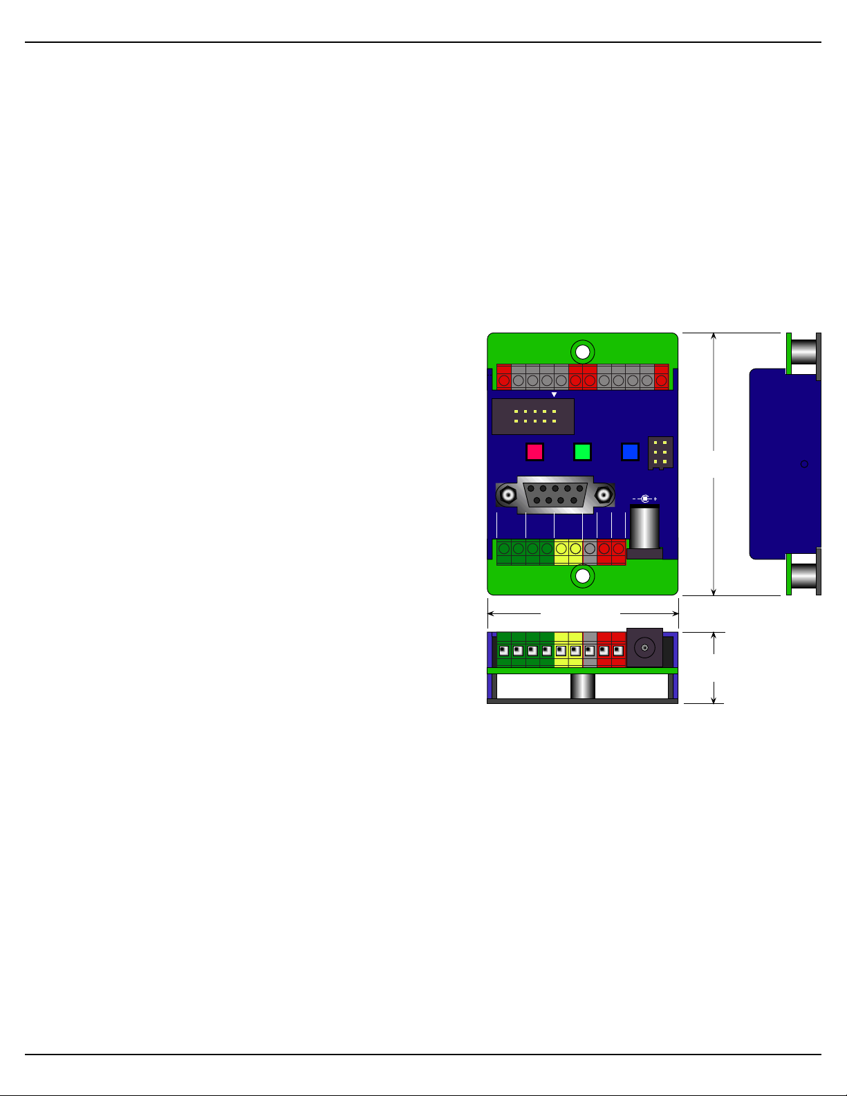
Gilderfluke & Co.• 205 South Flower Street • Burbank, California 91502 • 818/840-9484 • 800/776-5972 • fax 818/840-9485
2.75"
2.00"
0+1 2 3
+ +
4 5 6 7
+
+
-
S
Record
RS-232
1/4 J6
Go Data
TriggerATrigger
B
DMX-512
- in +
Servo
Power
Ground
9-24
vdc
9–24 vdc
1 2
Servos
Outputs
Br-miniBrick8
Gilderfluke & Company
Burbank, California
.75"
Br-miniBrick8 Overview
The Br-miniBrick8 can be used to control animated shows and displays, fountains,
fireworks, lighting, sound systems, simulators, slide and movie projectors, fiber optics,
window displays, motors, pneumatic and hydraulic systems, special effects, signs, machines and machine tools in process control, or anything else that can be controlled by
an electrical signal.
The Br-miniBrick8 is a complete stand-alone Show Control System. It can be used
singly, or in combination with additional Br-miniBrick8s, Smart Bricks, Dumb Bricks or
Digital Audio Repeaters. To add sound, use a Sd-10 or Sd-25 Audio Repeaters. If you
need fewer outputs, consider our Br-miniBrick4.
For more i/o, use the Br-MultiBrick32. For built
in animation and lighting control, audio repeaters,
and amplification, use our Sd-50 series of controllers. The Sd-50s are even available with
ʻAtomicʼ clock or GPS-based triggering based
upon time or position on the globe.
You can program the digital outputs of a Br-
miniBrick8 without a computer. Press and hold
the red ʻRecordʼ button until the first output
flashes. Press again to step to the output you
want to record. When you are ready to record,
press the green ʻGoʼ button. While you press
(and hold!) the red ʻRecordʼ button, anything you
do on the blue ʻDataʼ button is recorded on this
one output. Anything previously recorded on the
other outputs will play back as you record this
output. The Br-miniBrick8 will remember exactly
what you do and precisely when you did it. You repeat this until you have all eight outputs programmed just the way you want them.
To program the Br-miniBrick8 using a computer, you can ʻdrawʼ the sequence you
need on the screen of your computer using our included PC•MACs software. When
you have all of your shows completed (or just want to take a look at them), you can
download them to a Br-miniBrick8 in about twenty seconds through the standard RS-
232 serial port on your PC. You can then make additional changes and download again
and again until you are completely satisfied with your show. Once your show is perfect,
the PC can then go away. The Br-miniBrick8 will run by itself.
With the optional PC•MACs ʻRealTimeʼ license or PC•MACs hardware (MACs-USB
Smpte Card and a programming console), you can program in RealTime. PC•MACs
will remember exactly what you do and precisely when you did it. You can then use
Br-miniBrick8 v3.+ Manual / 8/17/12 / page 1 of 36
Page 8

Gilderfluke & Co.• 205 South Flower Street • Burbank, California 91502 • 818/840-9484 • 800/776-5972 • fax 818/840-9485
PC•MACsʼ editing tools to perfect the sequences you have programmed in RealTime.
When you have all of your shows completed, you can download them to a Br-
miniBrick8 through the standard RS-232 serial port on your PC. You can then make
additional changes and download again and again until your show is perfect. The PC
can then go away. The Br-miniBrick8 will run by itself.
Features of the Br-miniBrick8 include:
Automatic ʻprogram in placeʼ download through the standard serial port on your
•
PC. It takes about twenty seconds to download a fifteen minute show.
Digital outputs can be programmed without any computer using the three but-
•
tons on the front of the Br-miniBrick8.
Eight digital outputs rated for a continuous load of 150 ma., or 500 ma. peak.
•
This is enough to drive small solenoid valves, relays, LEDs and similar loads.
LEDs show all output activity. If more than eight outputs are needed, additional
Br-miniBrick8s can be stacked to give you as many outputs as you need.
Two outputs for controlling airplane-style ServoMotors. Endpoints are adjust-
•
able through the serial port. This allows up to 180º rotation on a standard Ser-
voMotor.
Input for standard DMX-512 data from light boards, Br-SmartMedia, MACs-
•
USB, Sd-50s, or any other source of standard DMX-512. DMX-512 is the stan-
dard protocol used for controlling all theatrical lighting equipment.
ʻRecordʼ, ʻgoʼ and ʻdataʼ buttons for programming digital data in RealTime with-
•
out any computer at all.
Each Br-miniBrick8 comes with a minimum of sixty-four KBytes of nonvolatile
•
memory. This gives a single channel show capacity of over thirty-six minutes at
thirty Frames Per Second! With eight digitals and one servo, you get more than
eighteen minutesʼ capacity. With eight digitals and both servos, you get about
twelve minutes of capacity at 30 Frames Per Second.
Once downloaded, show data is retained for approximately forty years, with or
•
without power applied.
You can rewrite the memory approximately fifty thousand times.
•
Two non-polarized optoisolated inputs to synchronize Br-miniBrick8s with
•
pushbuttons or other real-time events.
Multiple Br-miniBrick8s can be triggered simultaneously or sequentially.
•
Each Br-miniBrick8 input can be set to start, stop, pause, continue, or directly
•
select a specific show. LEDs show all input activity.
Two hundred fifty-five shows can be loaded onto a Br-miniBrick8 at one time
•
when using the PC•MACs software.
Shows can be accessed sequentially or directly using the two optoisolated in-
•
puts. Supports foreground/background shows.
The ʻnextʼ show can be set for the end of any show, allowing you to loop a sin-
•
gle show or build ʻchainsʼ of shows.
Br-miniBrick8 v3.+ Manual / 8/17/12 / page 2 of 36
Page 9

Gilderfluke & Co.• 205 South Flower Street • Burbank, California 91502 • 818/840-9484 • 800/776-5972 • fax 818/840-9485
The Br-miniBrick8 supports update rates from one frame per second to a
•
maximum of one hundred frames per second when using the PC•MACs soft-
ware. Different shows can each be programmed at different frame rates. This
allows you to program a ʻdelayʼ show that ticks along at a low frame rate between your main shows.
The eight digital outputs from a single Br-miniBrick8 can be fed to a Digital to
•
Analog converter (like our DAC-08) wherever you need a programmable 0-10
volt analog control signal.
The Br-miniBrick8 runs on anything from 9-24 VDC . Br-miniBrick8s can
•
even be run from batteries or solar cells.
Sturdy 2.75” x 2” x .75” aluminum case.
•
Br-miniBrick8s mount in standard Augat 2.75” ʻSnap Trackʼ, velcro, or using a
•
pair of screws.
Br-miniBrick8 v3.+ Manual / 8/17/12 / page 3 of 36
Page 10

Gilderfluke & Co.• 205 South Flower Street • Burbank, California 91502 • 818/840-9484 • 800/776-5972 • fax 818/840-9485
Br-miniBrick8 LEDs, Switches and Connections
There are only a small number of connections on each Br-miniBrick8. You will
need to attach a power supply, whatever you are controlling, and (optionally) a switch
(or two) to start the Br-miniBrick8:
LEDs:
1. Eight red LEDs show the status of the eight outputs. They also flash in a fast, very
bright ʻdouble flashʼ to indicate that an individual channel is enabled for programming
using the buttons on the Br-miniBrick8. These eight LEDs flash in a back-and-forth
chase to indicate that the Br-miniBrick8 is in the ʻclear allʼ mode, and that the buttons will be used to clear the memory of the Br-miniBrick8. During serial downloads, these eight LEDs will chase in a sequential pattern.
2. Two green LEDs show the status of the two optically isolated inputs. These LEDs
are located on the ʻinsideʼ of the optical isolators. They will operate if the input is receiving a signal, and it is getting to the Br-miniBrick8ʼs microprocessor. While setting the ʻoperating modeʼ for the Br-miniBrick8 using the buttons on its front, these
LEDs will flash in the same quick double-flash pattern as the red ʻoutputʼ LEDs.
When receiving DMX-512 or serial RealTime data, the Br-miniBrick8 no longer
needs the two trigger inputs or their indicator LEDs:
a. The ʻAʼ inputʼs LED is borrowed to toggle on each frame received. If receiving
DMX-512 data at 30 FPS, the LED will be flashing at 15 Hz.
b. The ʻBʼ inputʼs LED is borrowed to flash each time there is an error in the re-
ceived DMX-512 or Serial RealTime data. If you see this flashing any more
than occasionally, check your DMX-512 wiring. You may need to terminate
the DMX-512 data lines with a 120Ω resistor.
3. One LED is attached to the serial data transmission line on the Br-miniBrick8. The
Tx LED is used as a ʻheartbeatʼ so that you can see that the Br-miniBrick8 is alive.
If the RS-232 serial port is attached to a PC, then the flash will be very short and
quick, as the Br-miniBrick8 sends out a ʻfʼ to mark a frame, or a ʻ.ʼ if it is not currently running a show. When the RS-232 cable is disconnected, then this LED will
flash with a 50%/50% duty cycle. If this LED doesnʼt flash at least once per second,
you should power down the Br-miniBrick8 and check the power supply and connec-
tions to the Br-miniBrick8.
4. One LED is attached to the serial data received line on the Br-miniBrick8. If the RS232 serial port is attached to a PC, you will see this LED flash each time a data is
received through the serial port. If the RS-232 serial cable is disconnected, then the
LED will flash at a high rate of speed as DMX-512 data is being received.
Red ʻRecordʼ button:
The red ʻrecordʼ button is used for programming the Br-miniBrick8 without a com-
puter. See the ʻProgramming without a Computerʼ section of the manual for details on
the use of this button. The red ʻRecordʼ button electronically locks the Br-miniBrick8ʼs
nonvolatile EEprom memory whenever it is released. Nothing in the programming can
change unless this button is being held down. With the memory write protected, it
should retain whatever has been programmed into the Br-miniBrick8 for at least forty
years.
Br-miniBrick8 v3.+ Manual / 8/17/12 / page 4 of 36
Page 11

Gilderfluke & Co.• 205 South Flower Street • Burbank, California 91502 • 818/840-9484 • 800/776-5972 • fax 818/840-9485
Green ʻGoʼ button:
The green ʻgoʼ button is used for programming the Br-miniBrick8 without a com-
puter. See the ʻProgramming without a Computerʼ section of the manual for details on
the use of this button. The green ʻgoʼ button will start the Br-miniBrick8 as though the
trigger input ʻaʼ had been activated. Typically, this will start the first show playing.
Blue ʻDataʼ button:
The blue ʻdataʼ button is used for programming the Br-miniBrick8 without a com-
puter. See the ʻProgramming without a Computerʼ section of the manual for details on
the use of this button. If not actually recording a show using the buttons on the Br-
miniBrick8, this button can be used to cancel ʻrecordʼ mode, or to stop a show which is
playing by pressing it three times quickly.
RS-232 Serial Port:
This is a standard nine position PC-AT serial port connection. A nine pin male to nine
pin female serial cable (with ʻstraight throughʼ wiring!) should be used to connect the Br-
miniBrick8 to your PC. The only pins that the Br-miniBrick8 actually uses are the Txd,
Rxd and ground (pins #2, #3 and #5). This connection is used to download data to the
Br-miniBrick8. It can also be used with any GilderTerm or any standard modem program to talk to the Br-miniBrick8.
DMX-512 Input/Output:
The DMX-512 input/output on the Br-miniBrick8 is active ONLY when the RS-232
serial cable is not connected.
Note that DMX-512 output is available only on hardware versions 3.1 or greater and
firmware revisions 3.07 and later of the Br-miniBrick8. Version 3.0 Br-miniBrick8s can
be modified to output DMX at the Gilderfluke factory by updating the firmware and adding two wire jumpers.
DMX-512 is the serial data standard used to control ALL professional theatrical light-
ing equipment.
When used as an input, The DMX-512 terminals accept standard DMX-512 data
from any source of DMX-512 data. This DMX-512 can come from a lighting control
board, Br-SmartMedia, Br-Brain4, Sd-50, or any other source of DMX-512. The Br-
miniBrick8 will accept data with or without GilderChecksums. If receiving GidlerChecksums, the Br-miniBrick8 will not update its outputs on any DMX-512 packet that contains an error.
When used as an output, the Br-miniBrick8 can send up to sixty-four channels
worth of DMX-512 data to control dimmers, wiggle lights, smog machines, strobe lights,
or any other devices which accept DMX-512 data.
If used to send DMX-512 data to any Gilderfluke devices (other Br-miniBrick8s,
SER-DMX, etc.), the GilderChecksums can be enabled to assure that the data is received perfectly before it is used.
When GilderChecksums are not enabled, DMX-packets will be 512 channels in
length. This will allow frame rates up to about 40 FPS. If GilderChecksums are enabled,
the the DMX-512 packets will normally be limited to 256 channels (plus two channels for
the GilderChecksums) unless the data stored on the eeprom extends past the 256th
channel. This will cause the packets to be 512 channels in length.
To connect the Br-miniBrick8 to another DMX-512 device, wire the screw terminals
as follows:
Br-miniBrick8 v3.+ Manual / 8/17/12 / page 5 of 36
Page 12
Gilderfluke & Co.• 205 South Flower Street • Burbank, California 91502 • 818/840-9484 • 800/776-5972 • fax 818/840-9485
0+1 2 3
+ +
4 5 6 7
+
+
-
S
Record
RS-232
1/4 J6
Go Data
TriggerATrigger
B
DMX-512
- in +
Servo
Power
Ground
9-24
vdc
9–24 vdc
1 2
Servos
Outputs
Br-miniBrick8
Gilderfluke & Company
Burbank, California
Switch
Switch
Battery or Power Supply
MiniBrick8
Input 'A'
or 'B'
2.2 KΩ
Switch or Button
+ -
9 to 24 VDC
-
+
OptoIsolator
1. Connect the DMX-512 shield to the Br-miniBrick8 power supply ʻgroundʼ. This sig-
nal is normally found on pin #1 of a standard DMX-512 XLR-5 connector.
2. Connect the DMX-512 negative data to the DMX-512 ʻ-ʼ input. This signal is normally
found on pin #2 of a standard DMX-512 XLR-5 connector.
3. Connect the DMX-512 positive data to the DMX-512 ʻ+ʼ input. This signal is normally
found on pin #3 of a standard DMX-512 XLR-5 connector.
The Br-miniBrick8 uses a maximum of three data channels from the DMX-512. The
first channel is used for the eight digital outputs. The next consecutive DMX-512 channel is used for the first ServoMotor output. The next consecutive output is used for the
second ServoMotor output. The base address used for the DMX-512 and serial RealTime data is set using the configuration menu, or by sending an AutoDownload file to
the Br-miniBrick8 with the desired base address offset.
When receiving DMX-512 data, the Br-miniBrick8 no longer needs the two trigger
inputs or their indicator LEDs. They are used as follows:
a. The ʻAʼ inputʼs LED is borrowed to toggle on each frame received. If receiving
DMX-512 data at 30 FPS, the LED will be flashing at 15 Hz.
b. The ʻBʼ inputʼs LED is borrowed to flash each time there is an error in the re-
ceived DMX-512 or Serial RealTime data. If you see this flashing any more
than occasionally, check your DMX-512 wiring. You may need to terminate
the DMX-512 data lines with a 120Ω resistor.
If the Br-MiniBrick8 receives a DMX-512 signal on this input, or even spurious noise
that sounds to it a lot like DMX-512, it will stop running any animation sequence and
stop to listen for valid DMX-512 data. If no DMX-512 is received, then the animation sequence can be restarted by whatever means it has been configured to use (trigger or
power-up).
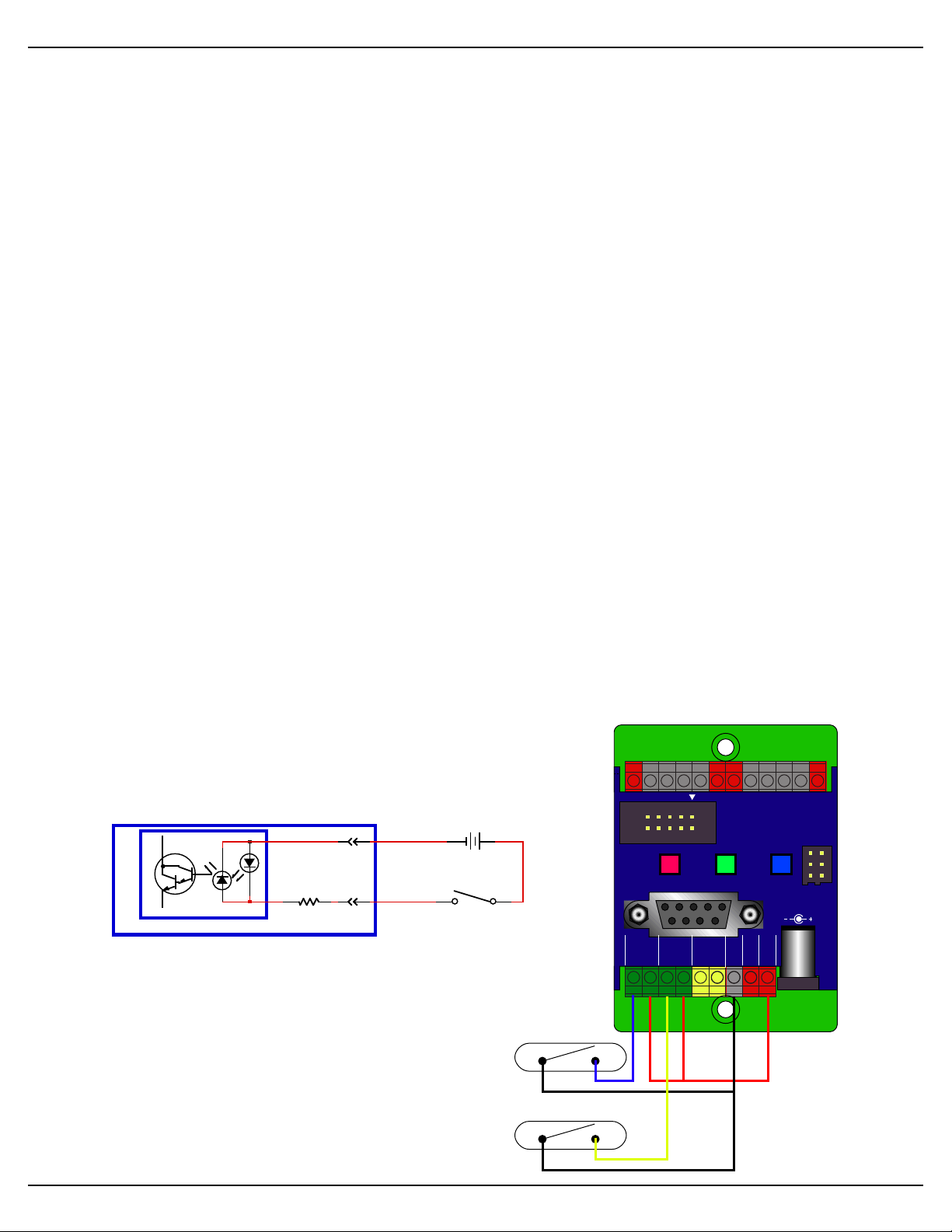
ʻAʼ & ʻBʼ Trigger Inputs:
The trigger inputs can be used to start, stop, pause or
select specific show sequences to play from any switch.
This can be a pushbutton, motion detector, IR beam, step
mat, or anything else that will give you a ʻswitch closureʼ.
The trigger input is non-polarized and optoisolated. You
must feed a voltage in to trigger it. You can ʻborrowʼ power
that is running the Br-MiniBrick8. The green LED lights
when a trigger input is active.
Any event can be triggered on either the
ʻclosingʼ or ʻopeningʼ edge of either input. A
ʻclosingʼ is when you apply a voltage to an in-
put. An ʻopeningʼ is when that voltage is removed. The inputs can be triggered on any
voltage from 9 to 24 VDC. If you donʼt have an
Br-miniBrick8 v3.+ Manual / 8/17/12 / page 6 of 36
Page 13
Gilderfluke & Co.• 205 South Flower Street • Burbank, California 91502 • 818/840-9484 • 800/776-5972 • fax 818/840-9485
0+1 2 3
+ +
4 5 6 7
+
+
-
S
Record
RS-232
1/4 J6
Go Data
TriggerATrigger
B
DMX-512
- in +
Servo
Power
Ground
9-24
vdc
9–24 vdc
1 2
Servos
Outputs
Br-miniBrick8
Gilderfluke & Company
Burbank, California
Servo Power Supply
(5 volts typically)
Main Power Supply
(9 to 24 volts)
or
external source of power for these two inputs, you can ʻstealʼ some juice from the BrminiBrick8ʼs power supply connections.
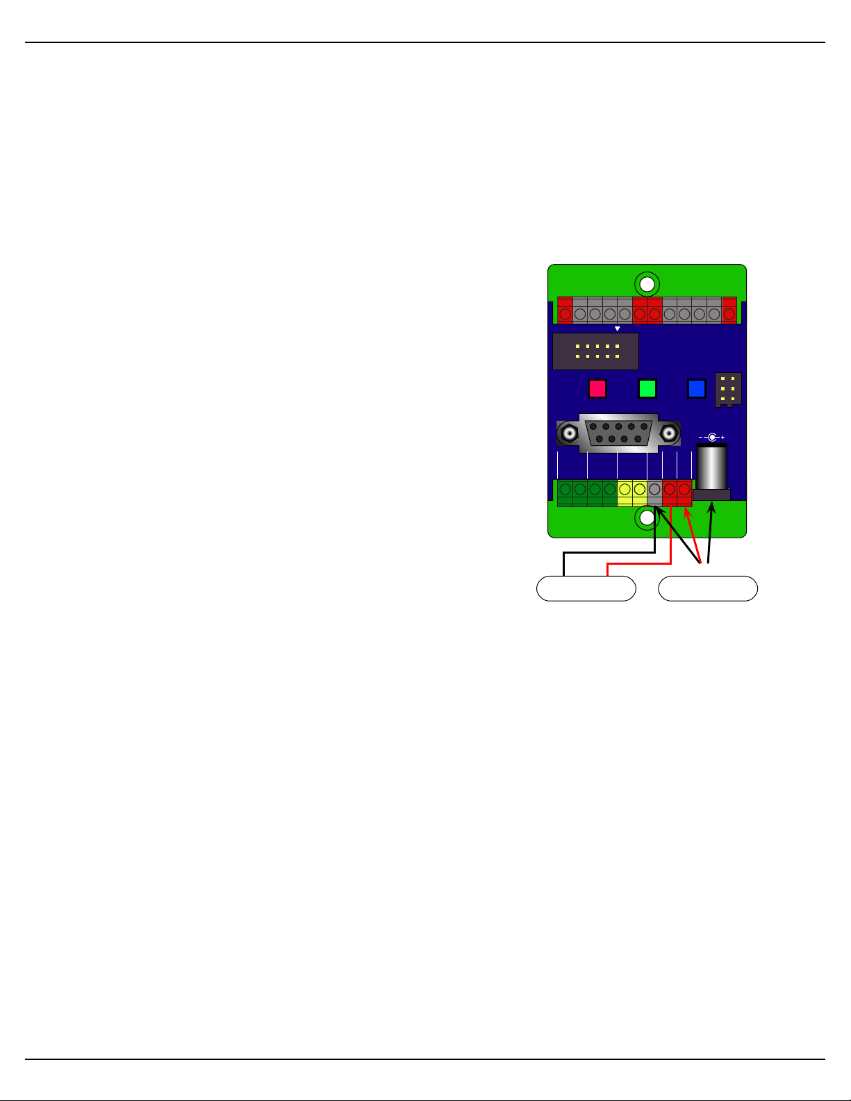
Power Supply:
The Br-MiniBrick8 will run on any voltage from 9 through 24 VDC. Whatever volt-
age you use will also be used to run the relays, valves and whatever you will be controlling. If you are controlling 24 VDC loads, you will want to use a 24 VDC power supply.
For 12 volt loads, use a 12 VDC supply. The Br-MiniBrick8 itself uses very little current.
Size your power supply so it will provide enough current to run all of your loads.
You can supply the power to the Br-miniBrick8 through
the 2.1 mm power jack, or through the screw terminals.
These connections are paralleled internally.
The power supply connection is protected from re-
verse polarity connections. An idle Br-miniBrick8 draws
only about twenty-five milliamperes. It can run for up to a
day on just a single nine volt battery even when it is running. The loads that the Br-miniBrick8 is controlling will
usually draw far more current than the Br-miniBrick8 itself.
ServoMotor Power Supply:
If you are using airplane-style ServoMotors with the
Br-MiniBrick8, you will need to provide a separate power
supply for your ServoMotors. Most ServoMotors will need
a power supply with a voltage rating of somewhere between four and six volts DC. Five volts DC is typical. You
should allow about an amp of current supply for each
typical ServoMotor motor being controlled. Larger ServoMotors may need a larger power supply.
The ServoMotor power input will accept any voltage up to 24 vdc, but this would fry
most ServoMotors. The ServoMotor power is attached directly to the two ServoMotor
connectors on the Br-miniBrick8. The Br-miniBrick8 makes no other use of the ServoMotor power.
ServoMotor Outputs:
Each Br-miniBrick8 has two outputs which can be used to control up to two model
airplane-style ServoMotors. To use these outputs, just plug in the ServoMotors and apply the appropriate voltage to the ServoMotor Power input (typically 5 vdc at 2 amps).
The two ServoMotors will be addressed with with the second and third channels of
data that the Br-miniBrick8 receives. With a typical base address of ʻ0ʼ, the first Ser-
voMotor will be addressed at ʻ1ʼ, and the second ServoMotor will be addressed at ʻ2ʼ.
The default pulse width on the Br-miniBrick8 is 1 to 2 ms. With most servoMotors,
this will rotate the shaft about 90º. The retract position and fully extended (maximum)
can be adjusted on the Br-miniBrick8 to give most ServoMotors the ability to rotate approximately 180º. See the Configuration Menu for instructions on adjusting the retract
position and fully extended (maximum) position of the ServoMotor outputs. Each ServoMotor output can be adjusted individually.
The Br-miniBrick8ʼs case will make it difficult to plug in most ServoMotors back-
wards, but not all brands of ServoMotors use the same polarization ʻbumpsʼ on their
connectors. If your ServoMotors donʼt have polarizing ʻbumpsʼ, then use the color code
Br-miniBrick8 v3.+ Manual / 8/17/12 / page 7 of 36
Page 14

MiniBrick8
Input 'A'
or 'B'
Self-Protecting
MOSFET
-
+
PTC Fuse
Relay/Solenoid
Output
Positive Common9 to 24 vdc
Gilderfluke & Co.• 205 South Flower Street • Burbank, California 91502 • 818/840-9484 • 800/776-5972 • fax 818/840-9485
0+1 2 3
+ +
4 5 6 7
+
+
-
S
Record
RS-232
1/4 J6
Go Data
TriggerATrigger
B
DMX-512
- in +
Servo
Power
Ground
9-24
vdc
9–24 vdc
1 2
Servos
Outputs
Br-miniBrick8
Gilderfluke & Company
Burbank, California
Relay or Solenoid
valve coils
Relay or Solenoid
valve coils
Relay or Solenoid
valve coils
Relay or Solenoid
valve coils
Relay or Solenoid
valve coils
Relay or Solenoid
valve coils
Relay or Solenoid
valve coils
Relay or Solenoid
valve coils
on the wires to determine the proper orientation for these connectors: The ʻ-ʼ wire is
usually brown or black. Note that most ServoMotors wonʼt be damaged by temporarily
being plugged in with the wrong orientation.
Digital Outputs:
Each Br-miniBrick8 has eight
digital outputs (hence, the name).
You can connect eight things to
the Br-MiniBrick8. These can be
LEDs, small motors, Solenoid
valves, relays, small lamps, or
anything else that needs 9 to 24
VDC, at less than 1/2 amp peak.
The outputs are just like the
standard outputs used on all Gilderfluke &
Company Show Control Systems. We switch
the negative sides of the outputs. You connect
the positive sides (usually the red wires) of the
eight things you controlling to either of the four
positive ʻcommonʼ terminals. The ʻnegativeʼ
sides of the eight things you are controlling
(usually the black wires) are connected individually to the eight outputs. These are numbered 0 through 7.
There is no ʻgroundʼ screw terminal on the
output ʻendʼ of the Br-miniBrick8. You can
pick up the ground at the power supply connection if needed.
The output connections for all Gilderfluke & Company Show Control Systems is
through ʻJ-6ʼ output cables. These are forty wire ribbon cables which are made up of
four identical eight bit wide ʻchannelsʼ. A J-6 cable is often split up into four individual
channels. Each ʻ1/4 J-6ʼ ribbon cable is made up of ten wires, and can be used to control eight individual ʻdigitalʼ (off/on) devices, or one eight bit wide ʻanalogʼ device. This is
what is found on a Br-miniBrick8
in addition to the screw terminal
connectors. Each group of ten
wires also includes a common
power supply and ground wire.
To s im p li f y w i ri n g t o a n y
Gilderfluke & Company animation system, the connectors used
mentʼ (IDS) connectors. These simply snap on to an entire cable, automatically ʻdisplacingʼ the wire insulation and making contact with the wires within. This means that an entire ten wire cable can be terminated in seconds. All connectors are polarized, to keep
them from being plugged in backwards. Although there are tools made specifically for
installing these connectors, the tool we find works best is a small bench vise.
Each 1/4 J-6 cable is arranged in the following order:
on the 1/4 J-6 cables are what
are called ʻinsulation displace-
Br-miniBrick8 v3.+ Manual / 8/17/12 / page 8 of 36
Page 15

Wire #
Color
Function
1
Brown
Circuit Ground
2
Red
Data bit 7
3
Orange
Data bit 6
4
Yel low
Data bit 5
5
Green
Data bit 4
6
Blue
Data bit 3
7
Violet
Data bit 2
8
Gray
Data bit 1
9
White
Data bit 0
10
Black
9-24 vdc Power
(PTC fused for 1 Amp)
Gilderfluke & Co.• 205 South Flower Street • Burbank, California 91502 • 818/840-9484 • 800/776-5972 • fax 818/840-9485
Any eight digital devices or one eight bit analog device can be connected to any 1/4
J-6 cable as shown. The LED between the ground (pin #1 brown) wire and supply (pin
#10 black) wire acts as an indicator which is lit if the fuse for that channel is OK.
All outputs are open collector switches to ground. Flyback diodes are included in the
outputs for driving inductive loads. Power is supplied through a diode and a solid state
circuit breaker to the common pin(s) on the connector. A safe level of current is 150 milliamperes simultaneously on each output. This is sufficient to drive most small relays,
valves and other similar loads directly. If fewer than eight outputs are on at one time,
then the outputs are rated as follows.
The supply line for each 1/4 J-6 is PTC fused for 1 amp. You should treat each 1/4 J-
6 as an individual, and not cross the outputs or supply lines from one channel to the
lines from any other channel. Doing this wonʼt cause any damage, but can reduce the
protection for the outputs that the fuses normally provide.
The current Output Capacity of each output is as shown in the following chart.
Since it is unusual to have more than 50% of the outputs on at any one time, you
can usually assume the system has at least a 250 ma output current capacity. If you are
going to be turning on lots of heavy loads at the same time, you should derate this to
150 ma.. This is sufficient to drive the majority of loads which will be directly connected
to the outputs of the animation system. If additional current capacity is needed, or if you
need to drive higher voltage loads, you can connect relays as needed to the outputs of
the animation system. Coincidentally, boards for doing this are available from
Gilderfluke & Company. These include:
1. DPDT relay board: A set of eight electromechanical relays with double pole/double
throw contacts rated at 5 amps each.
2. DRV-03: This is an eight channel, solid state relay board. Each output is PTC fuse
protected for up to 9 Amps of continuous current flow. It will work with DC voltages
between 9 and 24 volts.
Br-miniBrick8 v3.+ Manual / 8/17/12 / page 9 of 36
Page 16

Gilderfluke & Co.• 205 South Flower Street • Burbank, California 91502 • 818/840-9484 • 800/776-5972 • fax 818/840-9485
3. DRV-05: This is a specialty solid state driver board for use with up to eight PEM
Leapfrog Fountain jets. It has eight outputs, each rated for up to 5 amps at 24 vdc. It
runs on 9-24 VDC, and reverses the flow of current at the output when each is activated. It can also be used to reverse the running direction of small DC motors.
4. Reed relay board: A set of eight small electromechanical relays with normally open
contacts rated at 150 ma each.
5. I/O module: A set of eight small solid state relays with normally open contacts rated
at 3.5 amps each (alternating current and direct current relays available). Mounting
boards for I/O modules are available in 8, 16, 24 and 32 relay position modules.
6. Solid State Relay Fanning Strip: For connecting up to eight popular ʻhockey puckʼ
style relays to a 1/4 J-6 output cable. These are available with capacities of up to 75
amps each.
Br-miniBrick8 v3.+ Manual / 8/17/12 / page 10 of 36
Page 17

Gilderfluke & Co. Burbank, California * Br-miniBrick8 * v3.20 copyright 2009 DCM
a) Address- __0
1) Servo 1 endpoints (min: 128 | max: 130)
2) Servo 2 endpoints (min: 128 | max: 140)
b) DMX-512 Receive
c) use standard Digital Gilder-DMX
x) eXit
enter command-
Gilderfluke & Co.• 205 South Flower Street • Burbank, California 91502 • 818/840-9484 • 800/776-5972 • fax 818/840-9485
Configuration Menu
If you arenʼt using the ServoMotor outputs, you will not need to configure the Br-
miniBrick8. Even if you are using the ServoMotor outputs, you will only rarely need any
changes to the configuration. Using GIlderTerm, plug in the serial cable to the BrminiBrick8. Press the ʻconfigureʼ button to bring up the following menu:
As you can see, there arenʼt too many options available on this menu.
Set DMX-512 Address
This command is used to set the offset address for the Br-miniBrick8. By default
the Br-miniBrick8 uses DMX-512 or Serial RealTIme data addressed at zero for the
digital outputs, one as the first ServoMotor, and two as the second ServoMotor. This
command is one of two ways to set these offsets to any other address. No matter what
the base address is set to, all three data channels the Br-miniBrick8 will use are consecutive.
If using Serial RealTime data, keep in mind that there are only sixteen channels of
data being transmitted. If the address is set above sixteen, then the Br-miniBrick8 will
never see that data, as they are above its maximum address range.
If using DMX-512 data, feel free to set the address to anywhere between 0 and 511.
Keep in mind that most lighting boards and dimmers now number the DMX-512 addresses between 1 and 512 (our address ʻ0ʼ is their address ʻ1ʼ). If sending data from a
non-Gilderfluke system, you will need to offset the address of either the Br-miniBrick8
or the device which is sending the DMX-512 data by one address.
Br-miniBrick8 v3.+ Manual / 8/17/12 / page 11 of 36
Page 18

Gilderfluke & Co. Burbank, California * Br-miniBrick8 * v3.20 copyright 2009 DCM
use keypad as shown:
adjust--> min max position
|-----------------------|
Up--> | 7 | 8 | 9 |
|-----------------------|
middle--> | 4 | 5 | 6 |
|-----------------------|
Down--> | 1 | 2 | 3 |
|-----------------------|
1, 4, 7, - also set position to minimum
2, 5, 8, + also set position to maximum
<CR> to save, <Esc> to bail
original:
min | max |
128 | 130 |
new:
min.| max |position
128 | 130 | 123
Gilderfluke & Co.• 205 South Flower Street • Burbank, California 91502 • 818/840-9484 • 800/776-5972 • fax 818/840-9485
Set ServoMotor Endpoints
These two commands are used to set the endpoints for the two ServoMotor outputs.
By adjusting the endpoints, you can set how far the horn of your ServoMotor will rotate.
These commands will bring up the following menu:
Use the ʻ1ʼ, ʻ4ʼ and ʻ7ʼ keys to adjust the minimum position the ServoMotor will ever
go to. This will automatically force the output to the ʻzeroʼ position, and you can adjust
the ServoMotor to the spot where you would like to to be when fully retracted.
Use the ʻ2ʼ, ʻ5ʼ and ʻ8ʼ keys to adjust the maximum for the ServoMotor. This will
automatically force the output to the ʻfull scaleʼ position, and you can adjust the ServoMotor to the spot where you would like to to to be when fully extended.
You can then use the ʻ3ʼ, ʻ6ʼ and ʻ9ʼ keys to move the ServoMotor over the full range
of motion that will be available from the ServoMotor.
When you are satisfied with your adjustments, just hit the <Carriage Return> or ʻ0ʼ
key. If you donʼt want to save your settings, hit the <ESC>ape key to restore the original
values.
Typical RC radio rigs limit the pulses sent to the ServoMotors so that they have a
maximum travel of only about 90º. These are the default endpoint settings for the ServoMotor travel in the on the Br-miniBrick8. The Br-miniBrick8 will allow you to adjust
the pulses sent to the ServoMotors to a point beyond which most ServoMotors will follow. Most ServoMotors will go up as far as a 180º of movement. If your ServoMotor
starts to jitter, or looses all of its strength, then the pulse is probably set too long or too
short for the ServoMotor to follow.
Br-miniBrick8 v3.+ Manual / 8/17/12 / page 12 of 36
Page 19

Gilderfluke & Co.• 205 South Flower Street • Burbank, California 91502 • 818/840-9484 • 800/776-5972 • fax 818/840-9485
DMX-512
The DMX-512 input on the Br-miniBrick8 is active ONLY when the RS-232 serial
cable is not connected. The DMX-512 output is disabled if the RS-232 serial cable is
attached AND you send any serial command to the Br-miniBrick8 that generates a serial
response (requesting ʻstatusʼ or entering configuration). Sending show requests and
most other commands donʼt affect the DMX-512 output.
Note that DMX-512 output is available only on hardware versions 3.1 or greater and
firmware revisions 3.07 and later of the Br-miniBrick8. Version 3.0 Br-miniBrick8s can
be modified to output DMX at the Gilderfluke factory by updating the firmware and adding two wire jumpers.
DMX-512 is the serial data standard used to control ALL professional theatrical light-
ing equipment.
Press the ʻbʼ key to select the mode of operation for the DMX-512 port. Your choices
are:
1. DMX-512 Receive
2. DMX-512 Transmit (PCB version 3.1 or later only)
3. DMX-512 Transmit (w/checksums) (PCB version 3.1 or later only)
When used as an input, The DMX-512 terminals accept standard DMX-512 data
from any source of DMX-512 data. This DMX-512 can come from a lighting control
board, Br-SmartMedia, BsBrain4, Sd-50, or any other source of DMX-512. The Br-
miniBrick8 will accept data with or without GilderChecksums. If receiving GidlerChecksums, the Br-miniBrick8 will not update its outputs on any DMX-512 packet that contains an error.
When used as an output, the Br-miniBrick8 can send up to sixty-four channels
worth of DMX-512 data to control dimmers, wiggle lights, smog machines, strobe lights,
or any other devices which accept DMX-512 data.
If used to send DMX-512 data to any Gilderfluke devices (other Br-miniBrick8s,
SER-DMX, etc.), the GilderChecksums can be enabled to assure that the data is received perfectly before it is used.
When GilderChecksums are not enabled, DMX-packets will be 512 channels in
length. This will allow frame rates up to about 40 FPS. If GilderChecksums are enabled,
the the DMX-512 packets will normally be limited to 256 channels (plus two channels for
the GilderChecksums) unless the data stored on the eeprom extends past the 256th
channel. This will cause the packets to be 512 channels in length.
Firmware revisions 3.20 and later of the Br-miniBrick8:
All GilderGear uses the eight individual bits in a channel of DMX-512 data as eight
digital outputs. Lighting boards canʼt do this. They can only send analog values in each
DMX-512 channel. They have to use a whole DMX-512 channel to do just one digital.
Values above 50% turn the output ʻONʼ. Press the ʻcʼ key to toggle between the
Gilderfluke-style digitals and ʻanalogʼ style digitals that lighting boards use. The digitals
will be assigned to the eight consecutive DMX-512 channels after the ʻDMX addressʼ
(set above). The two ServoMotor outputs will be on the next two DMX-512 channels.
Exit Configuration
Press the ʻxʼ key, or the ʻConfig Doneʼ button on GilderTerm to exit configuration.
Br-miniBrick8 v3.+ Manual / 8/17/12 / page 13 of 36
Page 20

Gilderfluke & Co.• 205 South Flower Street • Burbank, California 91502 • 818/840-9484 • 800/776-5972 • fax 818/840-9485
Br-miniBrick8 Serial Port Commands
The Br-miniBrick8 can be accessed through the serial port from any computer running just
about any modem program. The computer you are using doesnʼt even need to have any
PC•MACs software installed on it. This is a feature that most users should never need to use.
We prefer to use our own ʻmodemʼ program, GilderTerm. If you donʼt have or canʼt download a copy of GilderTerm, then you can use just about any other terminal program. Typical
modem programs you can use are Terminal.exe (which comes with Windows 3.1) and Hyper
Terminal.exe (which comes with Windows ʼ95, ʼ98, W2K and XP). If you can, find a copy of
Terminal.exe, as it is a better program than the later Hyper Terminal. You can not download
files to a Br-miniBrick8 when using Hyper Terminal.
To use the Br-miniBrick8 with a terminal program, just connect it as you would normally
with a straight nine position male to nine position female cable. Configure your terminal program for 9600 baud, no parity, eight data bits, one stop bit and ʻxon/xoffʼ handshaking. GilderTerm defaults to these settings.
If the Br-miniBrick8 is not currently running a show, it will be printing the character ʻ.ʼ about
once a second. This is the ʻheartbeatʼ that you can see on the ʻheartʼ LED on the Br-
miniBrick8. When running a show, it will print the name of each show as it is started, and the
frame number on each frame update. If you do not see any of these characters, then there is a
problem with your physical connection or configuration.
Reset ʻj5AA5ʼ
This command will erase the EEprom on the Br-miniBrick8. The Br-miniBrick8 will
also determine the type and quantity of memory chips installed and report this and the
software revision number when it accepts this command.
Status ʻiʼ
When it receives this command, the Br-miniBrick8 will respond with the following
information on the Br-miniBrick8 (It will also print this information out when the Br-
miniBrick8 is first powered up or after a successful AutoDownload):
a) Firmware revision number and copyright.
b) Running status: Whether the Br-miniBrick8 is running, looping or stopped. What
show it is (or was) playing and the frame number into that show the Br-miniBrick8
is on.
c) Input status: Whether each input is opened (ʻOʼ) or closed (ʻCʼ).
d) Thirty-two byte header and name of the AutoDownload file that has been down-
loaded to the Br-miniBrick8.
e) One sixteen byte show header for each show that is loaded in the Br-miniBrick8.
AutoDownload ʻsA5A5ʼ nn
This is the format of the file that the Br-miniBrick8 will receive and load into its EEprom memory.
An AutoDownload file is a binary file. Any AutoDownload file that has previously
been saved can be sent to a Br-miniBrick8 by selecting the ʻsend binary fileʼ on your
modem program and selecting the AutoDownload for sending. You must be sure that
the modem program has not been set to ʻgobbleʼ any special characters (carriage returns, line feeds, etc.).
Br-miniBrick8 v3.+ Manual / 8/17/12 / page 14 of 36
Page 21

Gilderfluke & Co.• 205 South Flower Street • Burbank, California 91502 • 818/840-9484 • 800/776-5972 • fax 818/840-9485
The Hyper Terminal program that comes with Windows ʼ95, ʼ98, W2K and XP will not
work for sending AutoDownloads. For some strange reason it has been written to randomly change any binary value that is larger than one hundred twenty-seven.
Start Global ʻuʼ
This command is available ONLY firmware revisions 3.07 and later of the BrminiBrick8.
This command starts the animation playing on the Br-miniBrick8. The shows will
always start from the beginning. If the Br-miniBrick8 was previously looping shows, it
will have the ʻLOOPING SHOWSʼ flag reset.
At the end of a show which has been started using this command, the Br-
miniBrick8 will simply stop. If you need the Br-miniBrick8 to pay attention the ʻat endʼ
actions which were set when the show was downloaded, then you should use the ʻloopʼ
command instead.
If the Br-miniBrick8 receives a start command after it has received a request for a
specific show, it will play that show. Otherwise, it will play the show that has been set as
the ʻnextʼ show for the show which is currently playing (or most recently played show if it
is not currently playing). If this is the first show played after a Br-miniBrick8 is reset, it
will play the show which has been set as the ʻfirstʼ show during the AutoDownload. Requests for specific shows can come only from the serial port.
When shows are downloaded to the Br-miniBrick8, they can be set to ignore additional start commands while they are playing. This allows individual shows to be
ʻsteppedʼ upon or not. If the Br-miniBrick8 is already playing a show which has this op-
tion set, it will ignore this command.
Stop Global ʻyʼ
This command is available ONLY firmware revisions 3.07 and later of the BrminiBrick8.
This command unconditionally stops the Br-miniBrick8. The stop happens at the
current frame being played, and the outputs are frozen in the condition they were in
when the stop was received
Loop Global ʻ”ʼ
This command is available ONLY firmware revisions 3.07 and later of the BrminiBrick8.
These command acts much like the START commands, except they also set the
ʻLOOPING SHOWSʼ flag. At the end of the show, the Br-miniBrick8 will check for what
was set as the ʻat endʼ functions for the show which just completed, and take those actions. With this flag set, it is possible to set a sequence of shows playing in any order.
Since the ʻnextʼ show can be any show you ask for, one show can be played over and
over again, or you can set up a sequence of shows which will be repeated until the Br-
miniBrick8 is told to stop.
Select Show Global ʻ*ʼ [nn] (show#)
This command is available ONLY firmware revisions 3.07 and later of the BrminiBrick8.
Up to two hundred fifty-five different animated shows can be stored on a single BrminiBrick8. This command can be used to select an individual show on the selected
Br-miniBrick8. Individual shows can be requested using Hexadecimal numbers with a
range of 01 to FF. Once a show is selected, it will be played on the next serial port
Br-miniBrick8 v3.+ Manual / 8/17/12 / page 15 of 36
Page 22

Gilderfluke & Co.• 205 South Flower Street • Burbank, California 91502 • 818/840-9484 • 800/776-5972 • fax 818/840-9485
START or LOOP command. If a show is currently ʻloopingʼ, the requested show will be
played at the end of the next ʻloopʼ.
If a show selection has been made inadvertently, it can be cleared by sending a request for show number ʻ00ʼ.
Pause Show ʻ<00ʼ
Continue Show ʻ>00ʼ
These commands are available ONLY firmware revisions 3.07 and later of the BrminiBrick8.
Any show can be paused at any point during its playback. The outputs are frozen at
the levels they were at the instant the PAUSE command is received.
The CONTINUE command will resume playing any show playing which has previously been PAUSED.
Br-miniBrick8 v3.+ Manual / 8/17/12 / page 16 of 36
Page 23

Gilderfluke & Co.• 205 South Flower Street • Burbank, California 91502 • 818/840-9484 • 800/776-5972 • fax 818/840-9485
Programming the Br-miniBrick8 without a Computer
The digital outputs of the Br-miniBrick8 can be ʻProgrammed in Placeʼ using only
the three buttons on its top, or by connecting a RS-232 serial port and using Gilderfluke
& Co.ʼs PC•MACs software. The instructions in this section cover ʻPrograming-In-Placeʼ
using the buttons on the top of the Br-miniBrick8.
To enter programming mode:
Press and hold the red ʻRecordʼ button for three seconds. On the first press, the first
output (Output ʻ0ʼ) will begin flashing with a quick ʻdouble flashʼ pattern. This indicates
that only this one output is active for programming.
If the Br-miniBrick8 immediately starts a ʻback and forthʼ chase, it indicates that the
Br-miniBrick8 has had its memory cleared, and it has jumped right into the ʻclear allʼ
mode (see below).
On the next seven presses of the red ʻRecordʼ button, outputs ʻ1ʼ, through ʻ7ʼ are selected in turn.
On the eighth press, the ʻclear allʼ mode is selected. This is indicated by a ʻback-andforthʼ chase on all eight red output LEDs.
On the next four presses of the red ʻRecordʼ button, the ʻoperating modeʼ mode is
selected. This is indicated by a two short / one long flash pattern on one of the output
LEDs and the green ʻtriggerʼ LEDs. This mode is used to select whether the Br-
miniBrick8 is going to play the show once or loop, and whether the show can be
ʻstepped uponʼ once running.
On the next press, ʻprogrammingʼ mode is exited.
ʻClear Allʼ mode:
This is normally done as the first step in programming a show. This is how you set
the length of the show. Press and hold the red ʻRecordʼ button. Momentarily pressing
the green ʻGoʼ button (or if an external trigger is received) starts the Br-miniBrick8 run-
ning (yellow LED flashes quickly). The length of the show is set by the length of time
you hold down the red ʻRecordʼ button. When you release the red ʻRecordʼ button, the
show length will be set. While in this mode, outputs ʻ1ʼ through ʻ3ʼ are cleared. Bit ʻ0ʼ can
be programmed by pressing the blue ʻDataʼ button. By default, a new show is set to play
once when triggered, and canʼt be stepped on.
ʻRecord Oneʼ mode:
Once in ʻRecordʼ mode (entered by pressing the red ʻRecordʼ button until the first
output LED starts doing the ʻdouble flash. Press and release the red ʻRecordʼ button up
to seven more times, until you see the LED for the output you want to program doing
the ʻdouble flash.) Momentarily pressing the green ʻGoʼ button (or if an external trigger is
received) starts the Br-miniBrick8 running (yellow LED flashes quickly). Any outputs
which have previously been recorded will be played back. If the red ʻRecordʼ button is
pressed and held, it will clear the selected output. Pressing the blue ʻDataʼ button while
the red ʻRecordʼ button is held down will record new data on the selected channel.
If a portion of your show is perfect, and you only want to re-record a small section,
this is easily done with the Br-miniBrick8. Just release the red ʻRecordʼ button during
the sections of the show you want to keep. The data will not be altered. When the red
ʻRecordʼ button is pressed during the portions of the show you want to change, you can
alter the data by pressing (or not) blue ʻDataʼ button.
Br-miniBrick8 v3.+ Manual / 8/17/12 / page 17 of 36
Page 24

Gilderfluke & Co.• 205 South Flower Street • Burbank, California 91502 • 818/840-9484 • 800/776-5972 • fax 818/840-9485
Setting Operating Modes:
Press and hold the red ʻRecordʼ button. Press the red ʻRecordʼ button nine to twelve
more times, until you see the green ʻtriggerʼ LED and one of the four output indicators
flashing a two short / one long pattern:
a. Output 0 & ʻtriggerʼ LEDs: Play once, no step
b. Output 1 & ʻtriggerʼ LEDs: Play once, steppable
c. Output 2 & ʻtriggerʼ LEDs: looping, no step
d. Output 3 & ʻtriggerʼ LEDs: looping, steppable
Press and hold the red ʻRecordʼ button for three seconds to lock in the desired operating mode.
A show that is set to ʻplay onceʼ will only play when triggered, and then stop and wait
for the next trigger. A ʻloopingʼ show will start playing at PowerUp, and loop back to itself
at its end. It loops until powered down.
A show that is set to ʻno stepʼ will not allow another show to be started once it has
been started. This is used to keep shows from being retriggered repeatedly. It is used if
your show is started by a step pad, motion sensor, or other device which will send additional ʻstartʼ pulses before the show has run its course.
A shortcut to stop the Br-miniBrick8 playing or exit any ʻprogrammingʼ mode is to
release the red ʻRecordʼ button and quickly press the blue ʻDataʼ button three times.
This stops any show which was playing.
Br-miniBrick8 v3.+ Manual / 8/17/12 / page 18 of 36
Page 25

Gilderfluke & Co.• 205 South Flower Street • Burbank, California 91502 • 818/840-9484 • 800/776-5972 • fax 818/840-9485
Programming the Br-miniBrick8 with a Computer
This section of the manual is for those of you who arenʼt installing the MACs-USB Smpte
Card in their computer. If you do have a MACs-USB Smpte Card installed in your computer,
please refer to the appropriate sections of this or the PC•MACs manual. All of the real-time
features of PC•MACs are covered there.
The Br-miniBrick8 can be ʻProgrammed in Placeʼ using only the three buttons on its top,
or by connecting a RS-232 serial port and using Gilderfluke & Co.ʼs PC•MACs software. The
instructions in this section cover ʻPrograming-In-Placeʼ using our free PC•MACs software.
If you have ever drawn a ʻtiming chartʼ or schedule, this is exactly what you will be doing to
program the Br-miniBrick8. ʻTimeʼ is shown along the top of the page, and you draw in an
output where you want it ʻonʼ, and donʼt draw it in where you want it ʻoffʼ. All of the outputs can
change on every single update (typically there are 30 updates each second). The Br-
miniBrick8 just doesnʼt care if an output changes or not.
The next section of the manual gives an overview of programming using the PC•MACs Re-
alTime License. It assumes that you have already completed this section of the manual to
learn how to install the PC•MACs software, create a show, populate it with figures and channels, and perform rudimentary editing functions on the OffLine Editing Screen.
This section of this manual is excerpted from the (much larger) PC•MACs manual. Even
more commands and more details on the following commands can be found in other sections
of the PC•MACs manual. It can be downloaded from the Gilderfluke & Co. website.
Install the Software........
If the PC•MACs software has already been installed on the computer you are using,
you can skip this step.
PC•MACs is usually distributed on a CD-ROM, downloaded from our web page, or
received as a file attached to an Email. If you have the CD-ROM, just insert it in the appropriate receptacle in your computer. The CD will bring up a menu which will allow you
to install PC•MACs and other Gilderfluke & Co. software. All Gilderfluke & Co.ʼs manuals are also on this disk, and can be read using the included Acrobat PDF reader.
If you have downloaded or received the PC•MACs software via Email, it will probably be compressed into a ʻ.zipʼ file. You will first need to decompress this file. Your
browser or Email program may do this for you automatically. If not, you will need a program like unzip.exe or Win Zip to decompress them. Once this is done, just run the
ʻSetup.exeʼ program and follow the steps as it installs PC•MACs on your computer.
Getting started........
If the PC•MACs software is already running on the computer you are using, you can
skip this step.
The installation process will have left a shortcut to PC•MACs under the Windows
Start/Programs/Gilderfluke pulldown or on the desktop of your computer. You can start
PC•MACs by double clicking on either of these aliases, or navigating directly to the
PC•MACs.exe file and double clicking directly on it. If you tell the Windows registry
about PC•MACs, then it can start automatically any time you double click on a show or
site file.
Without the MACs-USB installed in your PC, you will be running in 'Software-Only'
mode. When you start the PC•MACs software, it will display the ʻmainʼ window, with a
message at its bottom that the Smpte Card hasn't been found, and the program is operating in ʻHardwarelessʼ mode.
Br-miniBrick8 v3.+ Manual / 8/17/12 / page 19 of 36
Page 26

Gilderfluke & Co.• 205 South Flower Street • Burbank, California 91502 • 818/840-9484 • 800/776-5972 • fax 818/840-9485
You will be able to access every feature of the PC•MACs program except for the
real-time commands (Play, Record, Rehearse, Single Step, etc.).
Select the serial port........
If a serial port has already been selected, or you arenʼt going to be downloading anything, you can skip this step.
If this is the first time that you have used PC•MACs, you will need to select the serial
port you are using. You can do this by opening the dialog under the Preferences
pulldown/Hardware/MiniBrick Interface.... Select the serial port you are going to be us-
ing. This serial port must not already be in use by any other function on your computer.
If it is, PC•MACs will give you a nasty message when you try to do an AutoDownload.
The selected serial port is stored as part of the Gilder.ini file. If it is an actual serial
port built in to your computer you will probably never need to select it again. If it is a
USB-to-Serial adapter, you may need to repeat this selection process every time Windows looses the USB serial port connection. Windows does this fairly regularly.
Starting a new show........
If you want to use a show that has already been created, just select the ʻFile
pulldown/Open...ʼ command to select and open an existing show. You can skip down to
the ʻEditing your show.....…ʼ paragraph below.
To start a new Show and Site File, select File pulldown/ʻNew...'. This opens the Show
Information dialog. For now, all we will do is create a new Site File, but this is where you
will normally set the length, frame rate and time code used with your show. All of these
can be changed at any time, so donʼt worry about them too much
When using Hardwareless RealTime mode, the only valid choices for Timecode are
ʻInternalʼ and ʻAudioʼ. In this case, we will choose ʻAudioʼ, so we can see a waveform
displayed graphically on the editing screen a little later. Select the radio button next to
the ʻAudioʼ selection. To actually select the audio or video file that you will be locking to,
press the ʻLoad Media Fileʼ button. You can select the ʻFiles of Typeʼ popup and select
either ʻAudio Filesʼ (any .wav, .mpa, mp2, mp3, .au or .aif file) or ʻVideo Filesʼ (any .avi,
.qt, .mov, .mpg or .mpeg file) to use. In this case, select ʻAudio Filesʼ and pick any
audio file to use.
If the length of the audio file you selected is different from what you have set for the
show length, PC•MACs will give you the opportunity of modifying the length. You can
leave the length unchanged, or automatically match the length of the audio or video file.
New shows default to using the ʻPC•MACsʼ Site File. To create a new Site File, select ʻNew...' from the Site File popup. Give it a simple name like ʻTestʼ when it asks for
one. If you had already created your own Site File and wanted to use it again for your
next show, you would just select it from the Site File popup.
Click the 'OK' button to close the Show Information dialog. At this point you have
created a blank show and a ʻnewʼ blank Site File. You will now need to create some outputs so that you can program them.
Creating some figures........
Open the Channels pulldown/Channels List dialog. At this point this list should be
pretty darned empty. After all, this is a brand new show!
FigureNames are used like a ʻfolderʼ on your computerʼs disk. You can put movement names into them to organize them and make them easier to manage. You can
create a FigureName by using the Channels pulldown/ʻCreate figure' command.
Br-miniBrick8 v3.+ Manual / 8/17/12 / page 20 of 36
Page 27

Gilderfluke & Co.• 205 South Flower Street • Burbank, California 91502 • 818/840-9484 • 800/776-5972 • fax 818/840-9485
You can modify any FigureName by selecting it and choosing Channels pulldown/
ʻModify' command or by simply double clicking on the FigureName you want to change.
Creating some output channels........
If you donʼt foresee ever using analog functions, then only create the digitals. If you
donʼt foresee ever using digital functions, then only create the analogs.
Open the Channels pulldown/Channels List dialog (if it isnʼt already opened).
First select (highlight) one of the figures that you have created. As a shortcut we will
then create eight digital channels followed by two analog channels by using the Channels pulldown/ʻCreate Multiple...'. This command will ask you for the number of analog
and digital channels you want to create. To keep things simple, select ʻzeroʼ analog and
ʻeightʼ digitals. Repeat the same steps but now select two analogs (eight bit resolution)
and zero digitals to be created.
This should have resulted in eight digital output channels addressed at 0.0 through
0.7, and two 8 bit resolution analog channels addressed at ʻ1ʼ and ʻ2ʼ. The analog channels will be used for the two ServoMotor outputs. They will all have the ʻdefaultʼ names.
The channels you have created are inside the ʻfigureʼ folders you previously created
(you did highlight the figures before creating the channels, didnʼt you?) To see the
channels you need to ʻopenʼ the FigureName. Left mouse click on the '>' at the left of
one of the FigureNames. This will open up the FigureName (the '>' turns into a 'V') so
you can see the channels within it. You can ʻcloseʼ a FigureName by clicking on the 'V'.
You can also create analog and digital channels one at a time by using the Channels
pulldown/ʻCreate Analog' or Channels pulldown/ʻCreate Digital'. If you select one of the
FigureNames you have already created, any output channels you create will be added
to this folder.
Name those channels........
You can modify any figure or channel by selecting it and choosing Channels
pulldown/ʻModify' command or by simply double clicking on it. You can then set the default levels for analogs (or ʻonʼ or ʻoffʼ for digitals), and the FigureName and figure assignment for a channel. PC•MACs wonʼt let you change an address to overlap with any
other existing channel. Leave the analog resolution at eight bits and donʼt modify the
address or bit number (digitals functions only) just yet.
You can use the ʻNextʼ/ʼLastʼ Buttons to view and edit the next or previous output
channel.
Close the Channels List by using the ʻCloseʼ box in the upper right corner or Channels pulldown/ʻHide Channels List' command.
Saving your show........
At this point it is time to save the work you have done so far. Because this is a new
show, the show remains ʻUntitledʼ. You can find the ʻSaveʼ command under the File
pulldown/ʻSave'. The first time you save a show, it will ask you for a ShowName. If you
want to save any show under a different name, you can always use the File pulldown/
ʻSave as...' command.
You should save the show often enough that you wonʼt get really pissed off if the
computer was to crash.
Editing your show........
If you have already moved the channels you want to edit over to the OffLine window,
you can skip the next step and open the OffLine window directly. Do this by pressing the
Br-miniBrick8 v3.+ Manual / 8/17/12 / page 21 of 36
Page 28

Gilderfluke & Co.• 205 South Flower Street • Burbank, California 91502 • 818/840-9484 • 800/776-5972 • fax 818/840-9485
OffLine button on the main window, or using the OffLine pulldown/ʻShow OffLine...'
command. PC•MACs will always remember the last channels that were edited for a
given site file.
Moving channels to the OffLine Editing window........
Now that we have some channels created, we can start editing them. Open the
OffLine pulldown/ʻMove to OffLine...' dialog. This dialog has two columns on it. In the left
column are all the figures and channels you have created. In the right column are the
channels you will be editing
You can select whole figures, or just some of the channels for editing by highlighting
them and pressing the ʻMove' button between the two columns. For this demo we have
only created two analogs and eight digitals. We might as well move them all over for editing. Press the 'OK' button when you are done. This will open the OffLine editing button.
On the OffLine Editing Window, you will see the analog functions displayed in the
upper pane. Since nothing has been programmed on the one analog functions yet, they
should appear as a horizontal colored line along the 50% mark at the middle of the analog pane.
Behind the analog functions is the waveform of the audio file you selected. If the
sound you selected has a good ʻbeatʼ, you will see regular pulses in it. The sound waveform is used as an editing aide to synchronize your sounds and movements. You can
also ʻpasteʼ a sound waveform into an analog or digital animation function using the
ʻYakʼ function.
The digital functions are shown in the lower pane. With nothing programmed into
them, the eight digitals will appear as eight light blue lines running horizontally along the
bottom of the digital window pane.
Where in the show are we?........
ʻShowʼ Time is displayed along the top of the window.
The time shown at the lower left corner of the screen is the time at the left side of the
window. The time shown at the lower right corner of the screen is the time at the right
side of the window. The time shown at the bottom center of the screen is the time at the
center of the window.
You can use the slider at the bottom of the screen to move to a different point in the
show, or modify any of these times to move to a different part of the show.
Change the amount of show you see.........
You can zoom in to see just a few frames of your show, or zoom all of the way out to
see the entire show at once. You can do this using the OffLine pulldown/Time Scale
commands, or Zoom time In, Zoom Time Out buttons on the pulldown at the top of the
screen.
You probably donʼt want to zoom in or out too far. If you zoom in too far you will only
see a tiny piece of your show. If you zoom too far out, you may not be able to see short
events. By default, PC•MACs will display two to four seconds of a show (depending on
screen resolution).
Which channel is which?........
As you move the cursor over any analog or digital function, you will see its name
displayed in the lower right corner of the window. This is how you can tell one channel
from another. The names of the digital functions are also displayed in little tiny type at
the left of the digital window pane.
Br-miniBrick8 v3.+ Manual / 8/17/12 / page 22 of 36
Page 29

Gilderfluke & Co.• 205 South Flower Street • Burbank, California 91502 • 818/840-9484 • 800/776-5972 • fax 818/840-9485
Rules to remember........
a. Channels are selected by clicking with the left mouse button.
b. If you left-click ON a channel, that ONE channel will be selected. If you click any
where BUT on a channel, ALL of the channels on the OffLine Window will be se-
lected.
c. Channels are modified by using the right mouse button.
d. Only the selected channels will be affected by any editing command. Channels that
are not being displayed on the OffLine Screen, or channels that are not selected, will
never be affected by anything that you do on the OffLine screen.
Selecting one or more channels for modification........
You can select a single channel for a stretch of time by left-clicking on that channel
and sliding the mouse to the left or right before releasing the mouse button. You can select all the channels that are being displayed by left-clicking anywhere on the screen but
on a channel and sliding left or right before releasing the mouse button. You can see
what channel(s) are selected by the width of the lines they are drawn with. When a
channel is selected, the lines get fatter.
Changing the channels you selected........
Individual channels can be selected or deselected by <shift>+left clicking anywhere
ON the channel you want to select or deselect. The channel will fatten or thin up to
show that it has been selected or deselected.
Another way to change the channels you selected........
You can double check which channels are selected by clicking on the ʻSelected
Channels' button at the bottom middle of the OffLine screen. This will bring up the ʻMove
to OffLine...' dialog again. Any channels that are selected will be highlighted in the right
column. You can change which channels are selected by highlighting and unhighlighting
channels in the right column of this dialog before you close it and go back to the OffLine
Window.
You can also use this dialog to move channels on or off the OffLine Editing window.
In general, you want to keep the OffLine Editing window as clear as possible. Display
only the channels you are going to be modifying.
Changing the amount of time selected........
Once you have one or more channels selected, you can change the amount of time
selected by modifying the times displayed at the bottom of the window. The entries that
are used for ʻfromʼ and ʻtoʼ times, and the ʻamount of time selectedʼ are the main ones
you might want to try changing. You can type in numbers, right-click or left-click, or click
and slide up and down or use the up down buttons on the keyboard to modify these
times. These numbers can be copied to other locations in the program, or copied from
other locations using the little ʻclock faceʼ popups next to each entry.
A second way to change the amount of time selected is to <shift>+left click anywhere in the white background area of the window (anywhere but on a channel). The
selected area will extend to the new click point.
Modifying digitals with a right mouse click........
You can draw or undraw any digital function by right-clicking on it and sliding the
mouse left or right. If you start on a point where the digital function is 'Off' (only a thin
line is showing), it will be drawn in. If you click on a spot where the digital is 'On' (where
the line is already fat), it will be turned 'Off' as you drag the mouse.
Br-miniBrick8 v3.+ Manual / 8/17/12 / page 23 of 36
Page 30

Gilderfluke & Co.• 205 South Flower Street • Burbank, California 91502 • 818/840-9484 • 800/776-5972 • fax 818/840-9485
If you press down the <shift> on your keyboard and right mouse click on a digital,
you can then ʻshiftʼ it left or right without changing its length.
Modifying analogs with a right mouse click........
Before trying this, make sure that the Preferences pulldown/Rubberbanding.... dialog
is set for ʻSplineʼ, with a default number of frames set to twenty.
Move the mouse over an analog function. Right Click on it and slide the mouse up or
down. When you release the button, the wave shape will be modified. If a range of time
has been selected, then that area will be Rubberbanded (instead of the default selection
you made for twenty frames).
Spline is the most commonly used tool. You can go to the Preferences pulldown/
Rubberbanding.... dialog and try out some of the other tools. The ʻ Pencilʼ tool requires
that a range of time be selected for it to work.
Cut, Copy and Paste, just like a word processor........
Once one or more channels have been selected, you can use the standard cut/copy/
paste functions that are used in every word processor known to mankind. The only difference is that here you are editing movements instead of sentences. These commands
are all found under the Edit pulldown.
Just like your work processor, if you cut out a paragraph, all the text after it will slide
forward in your document to fill the void. The same thing happens when you cut out a
stretch of one or more movements. Conversely, if you paste a sentence into a document, all the text after it will have to slide backwards to make room for it. The same
thing happens when you edit movement(s) in PC•MACs too. If you select a paragraph
in word processor and paste in a different paragraph that is exactly the same length, all
the text after will not need to move. Again, PC•MACs works in exactly the same way.
Paste something a bunch of times........
Something fun to try: Use the OffLine pulldown/ʻMove to OffLine...' command to
leave only three or four digital functions in the right column. Click ʻOK'. Now use the
right mouse button to draw in a chase pattern on these digitals. You should end up with
a pattern that looks something like a staircase. It can be an up or down staircase, at
your option. The steps can overlap or not. Now use the left button to click in the white
background of the window and select your staircase. Select the ʻCopy' command under
the Edit pulldown. Now select any single point on the OffLine Editing Window by clicking
on it with the left mouse button. Now select the Edit pulldown/ʻPaste Multiple...' command. Enter in the number of times you would like to see this chase pattern repeat and
click ʻOK'.
Cut, Copy and Paste to a file........
All of the cut, copy and paste commands you tried out in the last two sections can be
used to save one or more movements to files instead of the ʻclipboardʼ. Instead of using
the standard editing commands, select the File pulldown/ʻSave Macro...', File pulldown/
ʻInsert Macro...' and File pulldown/ʻInsert Multiple Macros...' commands. This allows you
to ʻpasteʼ in a movement that you ʻcopiedʼ months ago. The only limitation to the number
of Macro files you can save is the capacity of your hard disk.
Reverse events in time........
Now that you have a bunch of staircases, select one or more of them by left-clicking
anywhere except on the channels. Slide to the left or right until you have a complete sequence of steps selected and release the left mouse button. This selects all of the
channels that are currently displayed on the OffLine screen. Now select and Edit
Br-miniBrick8 v3.+ Manual / 8/17/12 / page 24 of 36
Page 31

Gilderfluke & Co.• 205 South Flower Street • Burbank, California 91502 • 818/840-9484 • 800/776-5972 • fax 818/840-9485
pulldown/ʻReverse' command. The selected stairway will now be reversed. This is useful
for programming chase sequences.
Stretch and compress time........
With one or more channel selected, you can then change the amount of time it takes
for the movement to take place. To do this, move the cursor up into the time bar. As you
do, you will see the cursor change into an ʻIʼ beam. If you right-click and slide the mouse
to the left or right, the selected channels will be compressed or stretched when you release the button. The data after the edit will slide forward or back in time to make room
for your changes.
Analog functions are interpolated when you stretch or compress them, so they come
out fairly cleanly. There arenʼt a lot of points between 'On' and 'Off' on a digital function,
so you may see some rounding errors on the digital functions. You can minimize this by
changing the new time to an even multiple of the original time.
Adding and subtracting time........
If a function happens too soon or late, you may need to shift it in time. Select one or
more channels for one or more frames worth of time. Use the Edit pulldown/ʻAdd time' to
move actions to a later time. Use the Edit pulldown/ʻDelete time' if you need the actions
to happen sooner. The selected movement(s) will shift by the number of frames you
have selected.
Generating a ramp between two points........
If you are only using digital channels, you should skip this step.
Select one or more analog channels for one or more frames worth of time. Select the
Edit pulldown/Inbetween command or <F10>. A ramp will be generated from whatever
levels the analogs are at the beginning of the selected area to whatever level they are at
the end of the selected area. The type of curve used for the ramp is set on the Preferences pulldown/Inbetweening dialog.
More ways to modify a digital channel........
If you are only using analog channels, you may want to skip this step.
Select one or more digital channels for one or more frames worth of time. Under the
Edit pulldown you can select the following commands to:
a. 'Clear to Default Values':! Sets any selected digital(s) back to their default values
(set for each channel under the Channels List). You can also use the ʻDeleteʼ key on
your keyboard as a shortcut to this command.
b. 'Fill with First Value':! The value at the start of the selected area is used to fill in the
rest of it.
c. 'Invert Valuesʼ: Where the digital was 'On', it is turned 'Off'. Where it was 'Off', it is
tuned 'On'.
d. 'Reverse Valuesʼ: The selected digital(s) are reversed in time.
e. 'Set to Yak...': Only if a .WAV file is used for audio synchronization. The audio wave-
form is transferred into the digital function(s).
f. 'Set Digitals Off': The selected digital function(s) are turned 'Off' in the selected area.
g. 'Set Digitals On': The selected digital function(s) are turned 'On' in the selected area.
More ways to modify an analog channel........
If you are only using digital channels, you may want to skip this step.
Br-miniBrick8 v3.+ Manual / 8/17/12 / page 25 of 36
Page 32

Gilderfluke & Co.• 205 South Flower Street • Burbank, California 91502 • 818/840-9484 • 800/776-5972 • fax 818/840-9485
Select one or more analog channels for one or more frames worth of time. Under the
Edit pulldown you can select the following commands to:
a. 'Clear to Default Values':! Sets any selected analog(s) back to their default values
(set for each channel under the Channels List). You can also use the ʻDeleteʼ key on
your keyboard as a shortcut to this command.
b. 'Fill with First Value':! The value at the start of the selected area is used to fill in the
rest of it.
c. 'Invert Valuesʼ: The selected analog channels(s) are inverted. As an example, a
value that was at 25% will be inverted to 75%.
d. 'Reverse Valuesʼ: The selected analog(s) are reversed in time.
e. 'Set to Yak...': Only if a .WAV file is used for audio synchronization. The audio wave-
form is transferred into the digital function(s).
f. 'Set Analogs to a Value...': You can enter a value for the selected analog(s).
g. 'Ramp to a value...': You enter the ending value for a ramp. A ramp is generated from
the existing value at the start of the selected area to the value you enter at the end
of the selected area.
h. 'Scale by Percentage...': The value you entered is added or subtracted from the se-
lected analog channel(s).
i. 'Smooth': This command applies a filter to the selected analog channel(s). This will
remove any jitter, and smooth out the highs and lows in an analog channel. The
value of this filter is set under the Preferences pulldown/ʻSmoothing' dialog. A larger
value will filter more. Each time you apply the filter to the same analog, it will be fil-
tered more. Eventually, you will end up with a flat line.
Save your show (again)........
Now that you have something programmed, you can now download it to the Bricks
you are using. You should save your work using the File pulldown/ʻSave' command. If
you donʼt, PC•MACs will not let you download the show in the next step.
AutoDownload your show........
If you have a Br-miniBrick8 attached to your PC, you will now want to try out the
AutoDownload functions of PC•MACs. Jump forward to the ʻAutoDownload Quick Startʼ
section of this manual to give it a try!
Br-miniBrick8 v3.+ Manual / 8/17/12 / page 26 of 36
Page 33

Gilderfluke & Co.• 205 South Flower Street • Burbank, California 91502 • 818/840-9484 • 800/776-5972 • fax 818/840-9485
Programming a Br-miniBrick8 with a RealTime License
This part of the manual is for those of you who arenʼt installing the MACs-USB Smpte Card
in their computer, but will be licensing the ʻHardwareless RealTimeʼ mode. If you do have a
MACs-USB Smpte Card installed in your computer or arenʼt licensing ʻHardwareless Real-
Timeʼ, you can skip reading this section of the manual.
This section of this manual assumes that you have already gone through the previous sec-
tion of this manual, where you learned how to create a show, and make the figures and output
channels you will be programming, and edit them using the OffLine Editing Window.
This is excerpted from the (much larger) PC•MACs manual. Even more commands and
more details on the following commands can be found in other sections of the PC•MACs manual. It can be downloaded from the Gilderfluke & Co. website.
Register your PC•MACs Software........
If the PC•MACs software has already been registered on the computer you are us-
ing, or you already have a MACs USB RealTime Dongle installed, you can skip this
step.
The MACs USB RealTime Dongle is the permanent license for the RealTime fea-
tures of PC•MACs. Gilderfluke & Co. can issue a temporary RealTime License number
as a temporary license, while the MACs USB RealTime Dongle is shipped to you. This
will enable the RealTime features of PC•MACs for fourteen days.
To obtain the temporary license for the Realtime features of PC•MACs, you will need
to register it with Gilderfluke & Co.. You can do this by opening the dialog under the
Preferences pulldown/Hardware/MiniBrick Security Key.... This shows a sixteen digit
ʻSystem Serial Numberʼ based upon your systemʼs hard disk drive, Windows, and the
date and time.
Contact Gilderfluke & Company with this number by phone, fax or Email, and we
will return a eight to ten digit long ʻSecurity Keyʼ. When you enter this ʻkeyʼ and press
the ʻValidateʼ button, all of PC•MACs RealTime features will be unlocked for fourteen
days. During this time, a MACs USB RealTime Dongle will be sent to you. Once the
MACs USB RealTime Dongle has arrived, it can be plugged into any PC that has our
software installed to permanently enable RealTime programming.
Install MACs USB RealTime Dongle........
If the PC•MACs software has already been registered on the computer you are us-
ing, or you already have a MACs USB RealTime Dongle installed, you can skip this
step.
Exit PC•MACs before beginning this procedure. It will not recognize the MACs USB
RealTime Dongle unless it was in place before it has started running.
The first time a MACs USB RealTime Dongle is plugged into a computer, Widows
will proudly announce that it has found new hardware, and hasnʼt a clue where to find
the appropriate drivers.
You will need to navigate Windows over to the C:/Programs/Gilderfluke/USB_Install
to find the appropriate driver. Being Windows, you will probably have to do this twice.
Now if you look under the Preferences pulldown/Hardware/MiniBrick Security Key....
Dialog, it will show that the MACs USB RealTime Dongle has been installed.
Note that this installation process will need to be repeated for any other computers
you want to install the PC•MACs software and Hardwareless Realtime programming.
Br-miniBrick8 v3.+ Manual / 8/17/12 / page 27 of 36
Page 34

Gilderfluke & Co.• 205 South Flower Street • Burbank, California 91502 • 818/840-9484 • 800/776-5972 • fax 818/840-9485
The MACs USB RealTime Dongle can freely be moved between any number of
computers. Only the computer that has the MACs USB RealTime Dongle installed at
the time will have access to the RealTime features of PC•MACs.
Select the serial port........
If a serial port has already been selected, you can skip this step.
If this is the first time that you have used PC•MACs, you will need to select the serial
port you are using. You can do this by opening the dialog under the Preferences
pulldown/Hardware/MiniBrick Interface.... Select the serial port you are going to be us-
ing. This serial port must not already be in use by any other function on your computer.
If it is, PC•MACs will give you a nasty message when you try to do an AutoDownload.
The selected serial port is stored as part of the Gilder.ini file. If it is an actual serial
port built in to your computer you will probably never need to select it again. If it is a
USB-to-Serial adapter, you may need to repeat this selection process every time Windows looses the USB serial port connection. Windows does this fairly regularly.
You are going to be updating your outputs through the serial port. You will need to
click ON the ʻRealTime MiniBrick Updatesʼ checkbox.
Plug in the Bricks........
If you have already plugged in your Pb-DMX/32 to the serial port, you can skip this
step.
It is now time to plug the Pb-DMX/32 into the serial port of your computer and power
it up. To connect the Pb-DMX/32 you will need a need a straight nine pin male to 1/8”
stereo plug cable.
Power up the Pb-DMX/32. For testing purposes, your power supply can be as simple as a couple of nine volt transistor radio batteries wired in series.
Assigning programming console inputs........
If you havenʼt done so already, open PC•MACs and the show you created in the
previous section of the manual.
Now that we have created some outputs in the previous section of this manual, we
need to assign them to the programming console so we can start RealTIme programming. When operating in Hardwareless Realtime Mode, your only choice for a programming console is the ʻSoft Consoleʼ.
Open the Soft Console using the RealTime pulldown/Show Soft Console command
or press the <F5> hot key shortcut. The Soft Console supports up to eight digital functions and two analogs at one time. Outputs are assigned by popping up the ʻAssignʼ
popups. This will display a list of the first sixteen eight bit wide channels you have created. Analog functions are shown by name. Digital functions are shown as ʻDigitals @
nnʼ. There are also entries in the popups to ʻUnassignʼ inputs.
Popup the digital ʻassignʼ popup and select one of the digital channels you created. If
you have something attached to the outputs, you probably want to pick a channel that
will be displayed on the outputs. The names of the individual digital bits will appear adjacent to each button on the Soft Console. You can then check the adjacent checkboxes
for the channels you want to make active. Any bits that are left unchecked will be left in
ʻplaybackʼ and the data will not be changed. You can press the digital function buttons
with the mouse on the screen, or use the number buttons ʻ1ʼ through ʻ8ʼ on your PCʼs
keyboard. Note that not all PC keyboards will let you press all eight number keys at the
same time. This is a limitation of the keyboards, and not PC•MACs.
Br-miniBrick8 v3.+ Manual / 8/17/12 / page 28 of 36
Page 35

Gilderfluke & Co.• 205 South Flower Street • Burbank, California 91502 • 818/840-9484 • 800/776-5972 • fax 818/840-9485
Popup the analog ʻassignʼ popup and select one of the analog channels you created.
Repeat this for the second analog input. If you have ServoMotors attached to the outputs, you probably want to pick a channel that will be displayed on the outputs. The
analogs can be moved by clicking anywhere on the Soft Console and sliding the mouse
left and right, up and down.
The ʻPunch Outʼ buttons allow you to temporarily place an input into ʻplaybackʼ (they
wonʼt alter the data) without unassigning them. The Momentary/Alternate button make
the digital inputs alternate action (push on/push off) or momentary. The Forward/
Reversed buttons allow you to reverse the sense of the two analog inputs.
Trying out your outputs........
If you havenʼt already, turn on ʻManual Modeʼ by pressing <F3> so that PC•MACs
starts updating the outputs. If 'Manual' mode is 'On', then whatever you do on the console will be sent out through the serial port. If you have any output devices attached,
you will see them change as you move the controls and/or push the digital buttons on
the console.
Press the digital function buttons with the mouse on the screen, or use the number
buttons ʻ1ʼ through ʻ8ʼ on your PCʼs keyboard. Move the analog functions by moving the
mouse to anywhere on the screen Soft Console Window and pressing the left mouse
button. The analogs will remain active for as long as you keep this button depressed.
The ʻPunch Outʼ buttons allow you to temporarily place an input into ʻplaybackʼ (they
wonʼt alter the data) without unassigning them. The Momentary/Alternate button make
the digital inputs alternate action (push on/push off) or momentary. The Forward/
Reversed buttons allow you to reverse the sense of the two analog inputs.
Saving console presets........
If you want to save the assignments you just made on your console, you can save a
ʻConsole Preset'. This takes a snapshot of everything you have assigned on the console. Select RealTime pulldown/ʻSave Console Preset...'. Give the Console Preset a
name or use the list of 'Standard Console names' popup to use one that has already
been saved. Once a Console Preset has been saved, it can instantly be recalled by the
popup in the middle of the PC•MACs Main Window or by the RealTime pulldown/ʻLoad
Console Preset....' dialog.
Now that some channel(s) have been assigned to the console, we can start programming.
Recording in RealTime........
Press the ʻRecord' button on the Main PC•MACs window (or use the Realtime
Pulldown/Record command or or <control>+<F1> on the keyboard). PC•MACs will start
advancing frames. Switch back to the Soft Console Window (if it got covered up) As you
move the analog controls (press and click the left mouse button) and press the digital
buttons you have assigned, whatever you do is being recorded as it is sent out the PCʼs
serial port. You can stop at any time by pressing the ʻStop' button on the screen or
<space bar> on the keyboard.
Playing it back........
To see what you just did, you can press the ʻPlay' button on the screen or <F1> on
the keyboard. PC•MACs will then play back what you just recorded. You can stop the
playback just as you stopped the Record, by pressing the ʻStop' button on the screen or
<space bar> on the keyboard.
Br-miniBrick8 v3.+ Manual / 8/17/12 / page 29 of 36
Page 36

Gilderfluke & Co.• 205 South Flower Street • Burbank, California 91502 • 818/840-9484 • 800/776-5972 • fax 818/840-9485
Saving your show (again)........
At this point it is time to save the work you have done so far. Use the File pulldown/
ʻSave' command. If you want to save any show under a different name, you can just use
the File pulldown/ʻSave as...' dialog.
One step forward, three steps back........
Now that you have done a pass or two, you can move on to programming some
other output channels.
You are going to go back a few steps to change the assignments on the console (optionally saving this as a new console preset) and record some data onto these other
channels too. You will see that as you record onto these new channels, the data you
programmed into the previous channels will be played back as well.
This is how a show is programmed. You typically program a channel or two at one
time, and then move on the next channels. Repeat these steps for as many channels as
you want to record.
Editing your show........
The last few steps of this ʻQuickStartʼ jump you back into the OffLine editing screen
from the last section of the manual. With RealTime features enabled, you can now review any changes you make instantaneously……….
If you have already moved the channels you want to edit over to the OffLine window,
you can skip the next step and open the OffLine window directly. Do this by pressing the
OffLine button on the main window, or using the OffLine pulldown/ʻShow OffLine...'
command. PC•MACs will always remember the last channels that were edited for a
given site file.
If you are running a show, pressing the OffLine button will open the OffLine Window
in ʻSingle Step Modeʼ. This is a shortcut that you may want to use later.
Reviewing the changes you have made........
After you make any edits, you can instantly review the changes you have made. You
will want to try this after many of the following steps.
You can start a show playing at any time by selecting Realtime pulldown/Play, or hitting the <F1> shortcut. As the show plays, you will hear the .wav audio file you selected
and see a ʻtime barʼ sweep across the screen to show where in time the show is. If the
OffLine pulldown/Auto Scroll check is ON, the OffLine Window will scroll to follow the
show as it plays.
You can stop a playback just as before, by selecting the Realtime pulldown/Stop, or
hitting the <Space> shortcut.
Changing the playback start point........
Unless you moved the ʻStartʼ slider on the main PC•MACs window, playback will begin at the start of the show. You can always go back to the main window to change the
start or stop sliders, but there are shortcuts to change them from the OffLine Window.
Position the OffLine window so you can see the part of the show you would like to
review. Pop up the ʻclockʼ shortcut at the lower left corner of the OffLine Window. Slide
down to the command to ʻPaste to Start Timeʼ. This pastes the time at the left side of the
screen into the ʻStartʼ slider on the main window. Now click on the ʻclockʼ shortcut at the
lower right corner of the screen. Slide down to the command to ʻPaste to Stop Timeʼ.
This pastes the time at the right side of the screen into the ʻStopʼ slider on the main win-
Br-miniBrick8 v3.+ Manual / 8/17/12 / page 30 of 36
Page 37

Gilderfluke & Co.• 205 South Flower Street • Burbank, California 91502 • 818/840-9484 • 800/776-5972 • fax 818/840-9485
dow. Now when you start a ʻPlayʼ, PC•MACs will playback the area displayed on the
OffLine window and then stop.
Single Step Playback........
You can enable Single Step Playback or Single Step Record using the commands
found under the OffLine pulldown.
When in Single Step Mode, the frame at the center of the OffLine Editing Window is
highlighted, and you can step your show forwards or backwards one frame at a time by
using the left and right arrow keys on your keyboard. You can move the cursor more tan
a single frame by editing any of the ʻtimeʼ numbers on the screen, or by dragging the
screenʼs scroll bar to another point in the show. The show will run at ʻsingle step speedʼ
to the newly selected point. (You can hit the <space bar> to cancel a long series of single Steps.)
Single Step Record Mode works identically, except that the programming console is
ʻactiveʼ, and any data on it will be recorded as you step forward through your show. This
is an easy way to define ʻkeyʼ frames in your show, that you can easily InBetween towards.
Single Step Playback can also be started at any time from the main window by hitting the ʻOffLineʼ button in the middle of a playback. This bounces you over to the
OffLine Editing Window with the frame that was playing at the center of the screen and
highlighted. This allows you to single step backwards and forwards to find any glitches
that may have been present in your show.
Save your show (again)........
Now that you have something programmed, you can now download it to the Bricks
you are using. You should save your work using the File pulldown/ʻSave' command. If
you donʼt, PC•MACs will not let you download the show in the next step.
AutoDownload your show........
If you have a Br-miniBrick8 attached to your PC, you will now want to try out the
AutoDownload functions of PC•MACs. Jump forward to the ʻAutoDownload Quick Startʼ
section of this manual to give it a try!
Br-miniBrick8 v3.+ Manual / 8/17/12 / page 31 of 36
Page 38

Gilderfluke & Co.• 205 South Flower Street • Burbank, California 91502 • 818/840-9484 • 800/776-5972 • fax 818/840-9485
AutoDownloading Your Shows to your Br-miniBrick8
This section of the manual is for those of you who are downloading your show(s) to a Br-
miniBrick8 for the first time. It will lead you through all of the steps necessary to send your
show(s) through the serial port for permanent storage on a ʻBrickʼ. You may need to refer to the
manuals for the specific ʻBrickʼ you are going to be downloading to
Your shows can have been programmed using PC•MACs in ʻSoftware-Onlyʼ, ʻHardwareless
Realtimeʼ, or with a MACs-USB Smpte card installed in your PC.
This section of this manual is excerpted from the (much larger) PC•MACs manual. Even
more commands and more details on the following commands can be found in other sections
of the PC•MACs manual. It can be downloaded from the Gilderfluke & Co. website.
Select the serial port........
If a serial port has already been selected, you can skip this step.
If this is the first time that you have used PC•MACs, you will need to select the serial
port you are using. You can do this by opening the dialog under the Preferences
pulldown/Hardware/MiniBrick Interface.... Select the serial port you are going to be us-
ing. This serial port must not already be in use by any other function on your computer.
If it is, PC•MACs will give you a nasty message when you try to do an AutoDownload.
The selected serial port is stored as part of the Gilder.ini file so you will never need
to select it again. If you canʼt connect with the Br-miniBrick8 through the serial ports,
you may need to try a different one.
Downloading to the Bricks........
Select the File pulldown/ʻSave as AutoDownload.....' command. This will bring up the
AutoDownload dialog. If this selection is grayed out on the pulldown menu, it means that
the serial port needs to be selected. See the previous step to set the serial port.
Plug in the Bricks........
If you have already plugged in your Br-miniBrick8 to the serial port, you can skip
this step.
It is now time to plug the Br-miniBrick8 into the serial port of your computer and
power it up. Br-miniBrick8 need a straight nine pin male to nine pin female cable.
Power up the Br-miniBrick8. For testing a Br-miniBrick8, your power supply can
be as simple as a nine volt transistor radio battery.
Reset the Br-miniBrick8........
To test if everything is hooked up OK, just press the ʻReset MiniBrickʼ button. A confirmation of the reset should appear on your screen (the ʻHeartʼ LED on the Br-
miniBrick8 should also flash).
Choose the shows to go into the Br-miniBrick8........
The show you have been working on will already appear on the list of shows to be
Auto Downloaded. If you want to download more than one show to the Br-miniBrick8,
just select the ʻAddʼ button and you can select additional shows. If more than a single
show is to be downloaded, you can use the ʻPromoteʼ and ʻDemoteʼ buttons to move selected file(s) up or down within the list.
If the same show is added to the list two or more times, only the first instance will
actually use up memory space. All subsequent instances of the show will only generate
a small header, which will refer to the data stored in the original instance.
Br-miniBrick8 v3.+ Manual / 8/17/12 / page 32 of 36
Page 39

Gilderfluke & Co.• 205 South Flower Street • Burbank, California 91502 • 818/840-9484 • 800/776-5972 • fax 818/840-9485
At this point you probably only have one show to download. This would be the one
you have been working on. Just leave this one show on the list of shows to be Auto
Downloaded to the Br-miniBrick8.
How many channels to send to the Bricks?........
You can now select the number of the channel to be downloaded to the Bricks. The
Br-miniBrick8 holds only a single channel for the digitals, or three channels if you are
using both of the ServoMotor outputs too. You can download more channels to the
Bricks, but this will just fill up the space in their memory needlessly.
The ʻFirst Channelʼ and ʻLast Channelʼ fields show the range channels to be downloaded.
Because a Br-miniBrick8 holds only a single channel if you are only using the digital outputs, both the ʻFirst Channelʼ and ʻLast Channelʼ values are set to ʻ0ʼ if you arenʼt
using the ServoMotor outputs. To download the digital AND the analog channels to a
Br-miniBrick8, set the ʻFirst Channelʼ to ʻ0ʼ and ʻLast Channelʼ values to ʻ2ʼ.
Where to send the file........
In most cases, you will want to set the ʻBrick Serial Addressʼ to zero when working
with Br-miniBrick8s. Because only one Br-miniBrick8s can be installed on the RS-
232 port at one time, they donʼt pay any attention to the ʻBrick Serial Addressʼ setting.
What will happen when the Brick is powered up?........
What will happen when the Br-miniBrick8s are first powered up (and right after an
AutoDownload). Touch the popup with the left mouse click and select the ʻloop from first
showʼ option. You can also select any show that is on the AutoDownload file list as the
first show that will be played.
Note that there is a subtle, yet very important difference between a ʻplayʼ and a ʻloopʼ
command. Both the ʻplayʼ and ʻloopʼ will start a show. The difference is at the end of the
show. A ʻplayʼ will simply get to the end of the show and do absolutely nothing. A ʻloopʼ
command will get the end of the show and then look around for what options have been
set for the end of the particular show which just finished. This can be to ʻdo nothingʼ, or
to jump to another show. When in doubt, it is always safer to use a ʻloopʼ command.
What will happen on each Brick input?........
You can select what will happen on the two optically isolated inputs by selecting either the ʻAʼ, ʻBʼ, ʻCʼ or ʻDʼ ʻradio buttonsʼ and using the popups to select what happens
on each edge of each input. You can also set specific shows to be played on any edge
of either input. A ʻclosingʼ is when you apply a voltage to an input. An ʻopeningʼ is when
that voltage is removed.
The Br-miniBrick8 has only two inputs. The ʻCʼ and ʻDʼ input selections are used for
configuring inputs for BR-MultiBrick32, Sd-50s and other devices made by Gilderfluke
& Company that have up to four inputs. Although any settings you make in the ʻCʼ and
ʻDʼ inputs will be downloaded to the Br-miniBrick8, it wonʼt do anything with them.
Note that there is a subtle, yet very important difference between a ʻplayʼ and a ʻloopʼ
command. Both the ʻplayʼ and ʻloopʼ will start a show. The difference is at the end of the
show. A ʻplayʼ will simply get to the end of the show and do absolutely nothing. A ʻloopʼ
command will get the end of the show and then look around for what options have been
set for the end of the particular show which just finished. This can be to ʻdo nothingʼ, or
to jump to another show. When in doubt, it is always safer to use a ʻloopʼ command.
Br-miniBrick8 v3.+ Manual / 8/17/12 / page 33 of 36
Page 40

Gilderfluke & Co.• 205 South Flower Street • Burbank, California 91502 • 818/840-9484 • 800/776-5972 • fax 818/840-9485
What will happen at the end of each show?........
Select any file in the list of shows to be Auto Downloaded. You can then use the
popup at the bottom of the AutoDownload window to set what will happen at the end of
each show. If you set it to jump immediately back to itself, the show will loop back on
itself until another show is started. You can also select whether another show can step
on the one that is currently running.
Do the deed........
Press the ʻDownloadʼ button. This will open a standard Mac/Windows ʻfile saveʼ dialog. The default name will be the name of the first show on the AutoDownload list. You
can change the FileName to any other legal name you wish. Press ʻOKʼ to start the
download. If this FileName has been used previously, then PC•MACs will ask if it is OK
to overwrite the older file. Go ahead and overwrite it.
A dialog with a progress bar will show the download taking place. You can cancel it if
you like, but if you do stop the download mid way you may need to power down the Br-
miniBrick8 and reset it before it can be talked to again..
An AutoDownload to a Br-miniBrick8 should take about twenty seconds at most. If
you AutoDownload takes more than a minute, it probably means that you are sending
more channels to the Br-miniBrick8 than you should. Go ahead and cancel, power
down and reset the Br-miniBrick8. Select the appropriate number of channels and try it
again.
Enjoy the results........
Because we set the Brick to play on power up, it will begin playing the show as soon
as the AutoDownload finishes. You should also get a confirmation of the AutoDownloadʼs success. If you selected any actions to take place on the two inputs, you can test
these as well.
Did it all fit?........
The Br-miniBrick8s have what is for most applications lots of extra memory space.
Now that you have downloaded the shows, you can check on how much space they
really occupy. Press the ʻReportʼ button. This will open up a report that is generated at
the same time as the AutoDownload file. This report is also saved to your disk under the
same FileName as the AutoDownload file, but with the extension ʻ.setʼ. You can open
this with Windows Notepad.
The value shown as the ʻEprom Endʼ for the last show in the set is the actual last
byte of data sent to the EEprom of the Br-miniBrick8. This will have to be well below
65,536.
Rinse and repeat........
If you want to make any changes in your show, you can close the AutoDownload dialog and use PC•MACs to make any more changes in the show. You can then AutoDownload again at any time. All the settings on the AutoDownload window will be saved
so that you donʼt need to enter them again on the next AutoDownload. The EEprom
memory on the Br-miniBrick8 is rated for at least fifty thousand downloads.
Br-miniBrick8 v3.+ Manual / 8/17/12 / page 34 of 36
Page 41

Gilderfluke & Co.• 205 South Flower Street • Burbank, California 91502 • 818/840-9484 • 800/776-5972 • fax 818/840-9485
Connect the equipment into an outlet on a circuit different
FCC and CE Compliance:
Br-miniBrick8s which are hardware revision 3.0 or later have
been tested to comply with FCC and CE requirements. Revisions earlier than this may have passed testing, but were not
certified at the time of manufacture.
Because Br-miniBrick8s are low voltage DC devices, neither
UL or CE require safety testing.
For fireproofing or additional radio frequency interference
shielding, Br-miniBrick8s can be mounted in a fire rated metallic case. Typically, this would be a NEMA-rated electrical
enclosure or 19” electrical rack.
•
from that to which the receiver is connected.
Consult the dealer or an experienced radio/TV technician for
•
help.
This equipment has been verified to comply with the limits for a
class B computing device, pursuant to FCC Rules. In order to
maintain compliance with FCC regulations, shielded cables
must be used with this equipment. Operation with nonapproved equipment or unshielded cables is likely to result in
interference to radio and TV reception. The user is cautioned
that changes and modifications made to the equipment without
the approval of manufacturer could void the user's authority to
operate this equipment.
FCC Instruction to User:
This equipment has been tested and found to comply with the
limits for a class B digital device, pursuant to part 15 of the
FCC Rules. These limits are designed to provide reasonable
protection against harmful interference in a residential installation. This equipment generates, uses and can radiate radio
frequency energy and if not installed and used in accordance
with the instructions, may cause harmful interference to radio
communications. However, there is no guarantee that interference will not occur in a particular installation. If this equipment
does cause harmful interference to radio or television reception, which can be determined by turning the equipment off and
on, the user is encouraged to try to correct the interference by
one or more of the following measures:
Reorient or relocate the receiving antenna.
•
Increase the separation between the equipment and re-
•
ceiver.
This device complies with Part 15 of the FCC
Rules. Operation is subject to the following two
conditions: (1) This device may not cause harmful
interference and (2) this device must accept any
interference received, including interference that
may cause undesired operation.
This Class B digital apparatus meets all requirements of the Canadian Interference-Causing
Equipment Regulations.
Cet appareil numerique de la classe B respecte
toutes les exigences du Reglement sur le
materiel brouilleur du Canada.
EC DECLARATION OF CONFORMITY
Friday, August 17, 2012
Application of Council Directives:! ! ! ! EMC Directive, 89/336/EEC
Manufacturer's Name:! ! ! ! ! Gilderfluke & Co., Inc.
Manufacturerʼs Address:! ! ! ! ! 205 South Flower St., Burbank, California 91502 USA
Importerʼs Name:! ! ! ! ! ! !!!!!!!
Importerʼs Address:! ! ! ! ! ! !!!!!!!
Type of Equipment:! ! ! ! ! ! Entertainment and Lighting Control
Equipment Class:! ! ! ! ! ! Commercial and Light Industrial
Model:! ! ! ! ! ! ! Br-miniBrick8
Conforms to the following Standards:! ! ! EN 55103-1: 1996 and EN 55103-2: 1996
Year of Manufacture:! ! ! ! ! 2006
I the undersigned, hereby declare that the equipment specified above conforms to the above directive(s)
and standard(s).
Place:!Burbank, California! ! ! ! ! Signature:! (signed)! ! ! !
Date: August 1, 2006! ! ! ! ! Full Name:! Doug Mobley
! ! ! ! ! ! ! ! Position:! CEO
Br-miniBrick8 v3.+ Manual / 8/17/12 / page 35 of 36
Page 42

Gilderfluke & Co.• 205 South Flower Street • Burbank, California 91502 • 818/840-9484 • 800/776-5972 • fax 818/840-9485
HEXadecimal to Decimal to ASCII to Percentage
This chart shows decimal, HEXadecimal, and a few percentage equivalents to aid you
when you need to convert between numbering bases:
! decimal! HEX!ASCII! %! decimal! HEX!ASCII! %! decimal! HEX!ASCII! % ! decimal! HEX!ASCII! %
! 00! 00h! null! 0%! 64! 40h! @! 25%! 128! 80h! (null)! 50%! 192! C0h! (@)! 75%
! 1! 01h! soh/^A! ! 65! 41h! A! ! 129! 81h! (soh)! ! 193! C1h! (A)
! 2! 02h! stx/^B! ! 66! 42h! B! ! 130! 82h! (stx)! ! 194! C2h! (B)
! 3! 03h! etx/^C! ! 67! 43h! C! ! 131! 83h! (etx/)! ! 195! C3h! (C)
! 4! 04h! eot/^D! ! 68! 44h! D! ! 132! 84h! (eot)! ! 196! C4h! (D)
! 5! 05h! eng/^E! ! 69! 45h! E! ! 133! 85h! (eng)! ! 197! C5h! (E)
! 6! 06h! ack/^F! ! 70! 46h! F! ! 134! 86h! (ack)! ! 198! C6h! (F)
! 7! 07h! bell/^G! ! 71! 47h! G! ! 135! 87h! (bell)! ! 199! C7h! (G)
! 8! 08h! bs/^H! ! 72! 48h! H! ! 136! 88h! (bs)! ! 200! C8h! (H)
! 9! 09h! ht/^I! ! 73! 49h! I! ! 137! 89h! (ht)! ! 201! C9h! (I)
! 10! 0Ah! lf/^J! ! 74! 4Ah! J! ! 138! 8Ah! (lf)! ! 202! CAh! (J)
! 11! 0Bh! vt/^K! ! 75! 4Bh! K! ! 139! 8Bh! (vt)! ! 203! CBh! (K)
! 12! 0Ch! ff/^L! ! 76! 4Ch! L! ! 140! 8Ch! (ff)! ! 204! CCh! (L)
! 13! 0Dh! cr/^M! ! 77! 4Dh! M! ! 141! 8Dh! (cr)! ! 205! CDh! (M)
! 14! 0Eh! so/^N! ! 78! 4Eh! N! ! 142! 8Eh! (so)! ! 206! CEh! (N)
! 15! 0Fh! si/^O! ! 79! 4Fh! O! ! 143! 8Fh! (si)! ! 207! CFh! (O)
! 16! 10h! dle/^P! ! 80! 50h! P! ! 144! 90h! (dls)! ! 208! D0h! (P)
! 17! 11h! dc1/^Q! ! 81! 51h! Q! ! 145! 91h! (dc1)! ! 209! D1h! (Q)
! 18! 12h! dc2/^R! ! 82! 52h! R! ! 146! 92h! (dc2)! ! 210! D2h! (R)
! 19! 13h! dc3/^S! ! 83! 53h! S! ! 147! 93h! (dc3)! ! 211! D3h! (S)
! 20! 14h! dc4/^T! ! 84! 54h! T! ! 148! 94h! (dc4)! ! 212! D4h! (T)
! 21! 15h! nak/^U! ! 85! 55h! U! ! 149! 95h! (nak)! ! 213! D5h! (U)
! 22! 16h! syn/^V! ! 86! 56h! V! ! 150! 96h! (syn)! ! 214! D6h! (V)
! 23! 17h! etb/^W! ! 87! 57h! W! ! 151! 97h! (etb)! ! 215! D7h! (W)
! 24! 18h! can/^X! ! 88! 58h! X! ! 152! 98h! (can)! ! 216! D8h! (X)
! 25! 19h! em/^Y! ! 89! 59h! Y! ! 153! 99h! (em)! ! 217! D9h! (Y)
! 26! 1Ah! sub/^Z! ! 90! 5Ah! Z! ! 154! 9Ah! (sub)! ! 218! DAh! (Z)
! 27! 1Bh! ESC! ! 91! 5Bh! [! ! 155! 9Bh! (ESC)! ! 219! DBh! ([)
! 28! 1Ch! FS! ! 92! 5Ch! \! ! 156! 9Ch! (FS)! ! 220! DCh! (\)
! 29! 1Dh! GS! ! 93! 5Dh! ]! ! 157! 9Dh! (GS)! ! 221! DDh! (])
!30!1Eh!RS! ! 94!5Eh!^! ! 158!9Eh!(RS)!! 222!DEh!(^)
! 31! 1Fh! VS! ! 95! 5Fh! ! ! 159! 9Fh! (VS)! ! 223! DFh! ( )
! 32! 20h! SP! 12.5%! 96! 60h! `! 37.5%! 160! A0h! (SP)! 62.5%! 224! E0h! (`)! 87.5%
! 33! 21h! !! ! 97! 61h! a! ! 161! A1h! (!)! ! 225! E1h! (a)
!34!22h!“! ! 98!62h!b! ! 162!A2h!(“)! ! 226!E2h!(b)
!35!23h!#! ! 99! 63h!c! ! 163!A3h!(#)! ! 227!E3h!(c)
!36!24h!$! ! 100!64h!d! ! 164!A4h!($)! ! 228!E4h!(d)
! 37! 25h! %! ! 101! 65h! e! ! 165! A5h! (%)! ! 229! E5h! (e)
! 38! 26h! &! ! 102! 66h! f! ! 166! A6h! (&)! ! 230! E6h! (f)
!39!27h!‘! ! 103!67h!g! ! 167!A7h!(‘)! ! 231!E7h!(g)
!40!28h!(! ! 104!68h!h! ! 168!A8h!(()! ! 232!E8h!(h)
!41!29h!)! ! 105!69h!i! ! 169!A9h!())! ! 233!E9h!(i)
!42!2Ah!*! ! 106!6Ah!j! ! 170!AAh!(*)! ! 234!EAh!(j)
! 43! 2Bh! +! ! 107! 6Bh! k! ! 171! ABh! (+)! ! 235! EBh! (k)
!44!2Ch!‘! ! 108!6Ch!l! ! 172!ACh!(‘)! ! 236!ECh!(l)
!45!2Dh!-! ! 109!6Dh!m! ! 173!ADh!(-)! ! 237!EDh!(m)
!46!2Eh!! ! 110!6Eh!n! ! 174!AEh!(•)! ! 238!EEh!(n)
! 47! 2Fh! /! ! 111! 6Fh! o! ! 175! AFh! (/)! ! 239! EFh! (o)
! 48! 30h! 0! ! 112! 70h! p! ! 176! B0h! (0)! ! 240! F0h! (p)
! 49! 31h! 1! ! 113! 71h! q! ! 177! B1h! (1)! ! 241! F1h! (q)
! 50! 32h! 2! ! 114! 72h! r! ! 178! B2h! (2)! ! 242! F2h! (r)
! 51! 33h! 3! ! 115! 73h! s! ! 179! B3h! (3)! ! 243! F3h! (s)
! 52! 34h! 4! ! 116! 74h! t! ! 180! B4h! (4)! ! 244! F4h! (t)
! 53! 35h! 5! ! 117! 75h! u! ! 181! B5h! (5)! ! 245! F5h! (u)
! 54! 36h! 6! ! 118! 76h! v! ! 182! B6h! (6)! ! 246! F6h! (v)
! 55! 37h! 7! ! 119! 77h! w! ! 183! B7h! (7)! ! 247! F7h! (w)
! 56! 38h! 8! ! 120! 78h! x! ! 184! B8h! (8)! ! 248! F8h! (x)
! 57! 39h! 9! ! 121! 79h! y! ! 185! B9h! (9)! ! 249! F9h! (y)
! 58! 3Ah! :! ! 122! 7Ah! z! ! 186! BAh! (:)! ! 250! FAh! (z)
! 59! 3Bh! ;! ! 123! 7Bh! ! ! 187! BBh! (;)! ! 251! FBh! ( )
! 60! 3Ch! <! ! 124! 7Ch! ! ! 188! BCh! (<)! ! 252! FCh! ( )
! 61! 3Dh! =! ! 125! 7Dh! |! ! 189! BDh! (=)! ! 253! FDh! (|)
! 62! 3Eh! >! ! 126! 7Eh! ~! ! 190! BEh! (>)! ! 254! FEh! (~)
! 63! 3Fh! ?! ! 127! 7Fh! del! ! 191! BFh! (/)! ! 255! FFh! (del)! 100%
Br-miniBrick8 v3.+ Manual / 8/17/12 / page 36 of 36
 Loading...