

Page 1

Gilderfluke & Co.• 205 South Flower Street • Burbank, California 91502 • 818/840-9484 • 800/776-5972 • fax 818/840-9485
Br-ANA
Sixteen Output Analog Card v4.nn
! The Br-ANA is used when you need to control anything that needs
a 0-10 vdc analog control voltage. These include animated shows,
lighting, motion base simulators, pneumatic and hydraulic systems,
special effects, signs, fountains, and more.
A Digital device is either on or off, like a light switch. An Analog device
is on, off, or at any point between, like a light dimmer. The speed of the
change is set by how fast you turn the knob. In animation, analog
movements give the fluid, lifelike movements needed to bring an ani-
mated figure to life. They can move fast, slow or anywhere in between.
! Br-ANA is a controller with sixteen 0-10 volt analog outputs, a full
512 channel universe of DMX-512 input and output and a legacy port for
attaching Z-Bricks. The analog outputs are oversampled at four times the
showʼs frame rate, so they are typically updated at 120 Hz for ultra
smooth analog outputs.
! For storing shows, the Br-ANA uses any standard Sd or
SdHC flash card. These can hold months worth of shows! For
triggering those shows, there are four optically isolated inputs, or
the RS-422 networkable serial port can be used.
Br-ANAs can be used as standalone show controllers, as a ʻmasterʼ, controlling slaves attached to a DMX-512 network, or they themselves can be
ʻslavesʼ, following data sent to them through a DMX-512 network.
! The Br-ANA can also be used a as ʻSmartʼ Brick, receiving time code
information from a ʻSmartʼ Brick Brain, and using this time code to access
the shows stored on its local Sd- or SdHC flash card to update its outputs.
Br-ANA Manual / December 18, 2012 10:21 AM / page 1 of 60
Page 2

Safety Disclaimer: Any electronic or mechanical sys-
tem has a potential to fail. Certain applications using
Gilderfluke & Company equipment may involve poten-
tial risks of death, personal injury, or severe property, or
environmental damage (“Critical Application”).
Gilderfluke & Company equipment is not designed, in
-
tended, authorized, or warranted to be suitable in life
support applications, devices, or systems, or other
critical applications. Inclusion of Gilderfluke & Com-
pany products in such applications is understood to be
fully at the risk of the customer. In order to minimize
risks associated with the customer's applications, ade-
quate design and operating safeguards should be pro-
vided by the customer to minimize inherent or proce-
dural hazards.
Gilderfluke & Company assumes no liability for appli-
cations assistance, customer produced design, soft-
ware performance, or infringement of patents or copy-
rights. Nor does Gilderfluke & Company warrant or rep-
resent that any license, either express, or implied, is
granted under any patent right, copyright, mask work
right, or other intellectual property right of Gilderfluke &
Company covering or relating to any combination, ma-
chine, or process in which Gilderfluke & Company
products or services might be or are used.
Gilderfluke & Co.• 205 South Flower Street • Burbank, California 91502 • 818/840-9484 • 800/776-5972 • fax 818/840-9485
Br-ANA Manual / December 18, 2012 10:21 AM / page 2 of 60
Page 3

Gilderfluke & Co.• 205 South Flower Street • Burbank, California 91502 • 818/840-9484 • 800/776-5972 • fax 818/840-9485
..................................................................................Br-ANA Overview! 7
....................................................................Br-ANA Panel Indicators! 11
.....................................................................................Output Fuse Indicators! 11
.....................................................................................Output Level Indicators! 11
.....................................................................................................J8 Input LEDs! 11
............................................................................................................Busy LED! 11
..........................................................................................................Read LEDs! 12
................................................................................................Board Error LED! 13
.....................................................................................................DMX-512 LED! 13
..................................................................................Brain Heart/Running LED! 13
....................................................................................................Heartbeat LED! 14
............................................................................Br-ANA Connectors! 15
................................................................................................................Z-Brick ! 15
...................................................................Sd/SdHC Flash Memory Card Slot! 16
........................................................................................Backplane Connector! 16
............................................................ʻSmartʼ Brick Network (on Card Cage)! 19
................................................................................ʻJ8ʼ Inputs (on Card Cage)! 20
..........................................................................Power Supply (on Card Cage)! 22
...................................................................RS-422 Serial Port (on Card Cage)! 23
..............................................................DMX-512 Data In/Out (on Card Cage)! 24
.......................................................Br-ANA Hardware Configuration! 27
..............................................................................................................Address! 27
..........................................................................................Write Protect Switch! 27
.....................................................................Smart' Brick/'Dumb' Brick Select! 28
.............................................................................................................J8 Power! 28
................................................................................................Full Scale Adjust! 29
........................................................Br-ANA Software Configuration! 31
.....................................................................................................First Address:! 34
.........................................................................................twelve bit resolution:! 34
..........................................................................................Sequencer Enabled:! 35
..................................................................................................DMX-512 mode:! 35
........................................................^d) DMX-512 Zero-Based or One-Based:! 35
......................................................................................................Auto Ease-In:! 36
...........................................................................................Numbering System:! 37
....................................................................................Output to Test & Adjust:! 37
........................................................................................................Test Output:! 37
......................................Set Minimum, Maximum and Forced using Keypad:! 38
.................................................................................Force Outputs to a Value:! 40
............................................................................................Power On Defaults:! 40
......................................................................................Set Analog Endpoints:! 41
....................................................................................................................Next:! 41
....................................................................................................................Last:! 41
........................................................................................................Card Status:! 42
................................................................................................Reload Defaults:! 44
...........................................................................................................Play/Loop:! 44
Br-ANA Manual / December 18, 2012 10:21 AM / page 3 of 60
Page 4

Gilderfluke & Co.• 205 South Flower Street • Burbank, California 91502 • 818/840-9484 • 800/776-5972 • fax 818/840-9485
.....................................................................................................................Halt:! 44
.....................................................................................................Save Configs:! 45
..................................................................................................................Verify:! 45
.....................................................................................................................eXit:! 46
...........................................Optically Isolated Trigger Input Actions! 47
.............................................................................................................not used:! 48
.........................................................................................................Start Show:! 48
.........................................................................................................Stop Show:! 48
.......................................................................................................Stop At End:! 48
......................................................................................................Pause Show:! 48
..................................................................................................Continue Show:! 49
......................................................................................................E-stop Show:! 49
......................................................................................................Clear E-stop:! 49
........................................................................................Sequential From List:! 50
............................................................................................Random From List:! 50
....................................................................................................Reshuffle List:! 51
......................................................................................................Analog Limit:! 51
...........................................................................................................Binary Bit:! 51
.......................................................................Serial Port Commands! 53
..............................................................................................Echo Commands:! 54
.........................................................................................................Card Reset:! 55
........................................................................................................Card Status:! 55
...............................................................................................Start Commands:! 56
...............................................................................................Stop Commands:! 57
..............................................................................................Loop Commands:! 57
...................................................................................Stop at End Commands:! 57
..................................................................................Select Show Commands:! 58
..................................................................................Show Pause Commands:! 58
.................................................................Br-ANA Firmware Updates! 59
...........................................HEXadecimal to Decimal to Percentage! 60
Br-ANA Manual / December 18, 2012 10:21 AM / page 4 of 60
Page 5

Gilderfluke & Co.• 205 South Flower Street • Burbank, California 91502 • 818/840-9484 • 800/776-5972 • fax 818/840-9485
this page is not blank
Br-ANA Manual / December 18, 2012 10:21 AM / page 5 of 60
Page 6
Gilderfluke & Co.• 205 South Flower Street • Burbank, California 91502 • 818/840-9484 • 800/776-5972 • fax 818/840-9485
A note about this manual:
This manual covers the specifics of the Br-ANA. To
program the Br-ANA you will also want to refer to the
PC•MACs manual sections that cover the PC•MACs
software.
The Br-ANA is typically programmed in ‘Software-only’
or ‘Hardwareless RealTime’ mode. If you are using the USB-
DMX for programming your Br-ANA through the DMX-512
inputs, please refer to the PC•MACs ‘Unlimited’ mode.
The full PC•MACs manual can be downloaded from our
web site at:
http://www.gilderfluke.com
Br-ANA Manual / December 18, 2012 10:21 AM / page 6 of 60
Page 7

Gilderfluke & Co.• 205 South Flower Street • Burbank, California 91502 • 818/840-9484 • 800/776-5972 • fax 818/840-9485
Br-ANA Overview
The Br-ANA is an output card which has sixteen 0-10 volt analog outputs, DMX-512
input and output and a legacy port for attaching Z-Bricks
it uses any standard Sd or SdHC flash card. For triggering those shows, there are four
optically isolated inputs, or the RS-422 networkable serial port can be used.
The outputs on the Br-ANA can be set to use either eight or twelve bits of resolution.
They are designed to be used as stand-alone show controllers, as a ʻmasterʼ sending
data to other devices that act as ʻslavesʼ on a DMX-512 network, or as ʻslavesʼ themselves, receiving DMX-512 data from a ʻmasterʼ elsewhere on the DMX-512 network:
1) Br-ANA running standalone or acting as a ʻMasterʼ: In this mode of op-
eration, data for the outputs is stored in the standard Sd or SdHC flash card.
! The Br-ANA when running standalone or acting as a ʻMasterʼ can use one
of two sources for the frame rate clock:
a) Br-ANA in ʻDumbʼ Brick Mode:
1
. For storing up to 255 shows,
Switch #4 must be in the ʻDumbʼ Brick position to operate as a ʻDumbʼ
Brick. There should never be both ʻSmartʼ and ʻDumbʼ Bricks in the same
card cage. Damage may result if there are.
When in ʻDumbʼ Brick mode, the shows can be triggered by the four
switch closure inputs, low speed RS-422 serial port inputs, or shows can
be set to run continuously. The clock source for all shows once they are
started is the high accuracy crystal oscillator (+/- 25 PPM) on the Br-ANA.
Multiple ʻDumbʼ bricks can be triggered simultaneously, but this is not
generally recommended as a way to synchronize multiple units. The far
better way of synchronizing is by sending data stored on the designated
ʻmasterʼ to all the ʻslavesʼ attached to a DMX-512 network.
This Br-ANA acts just like any other Playback-Only 'Dumb' Brick, playing animation data from the Sd Flash card. The Br-ANA can be set to
start and play a show at power up, or only play when triggered to do so.
The Br-ANA then uses the show data stored in the Flash Memory to update its analog and DMX-512 outputs at the appropriate frame rate.
b) Br-ANA in ʻSmartʼ Brick Mode:
Switch #4 must be in the ʻSmartʼ Brick position to operate as a ʻSmartʼ
1
The Z-Brick connector is a legacy connection. It is there just for backwards-compatibility on existing systems. It is highly recommended that you do not use the Z-Brick connector for attaching Z-Bricks. Instead, just send DMX-512 to them just as you would for
any other GilderGear. The Z-Brick connector will likely not be installed unless specifically requested on new builds of Br-ANAs.
Br-ANA Manual / December 18, 2012 10:21 AM / page 7 of 60
Page 8

Gilderfluke & Co.• 205 South Flower Street • Burbank, California 91502 • 818/840-9484 • 800/776-5972 • fax 818/840-9485
Brick. There should never be both ʻSmartʼ and ʻDumbʼ Bricks in the same
card cage. Damage may result if there are.
A ʻSmartʼ Brick system is used when you need to synchronize any
number of ʻBricksʼ together on a ʻSmartʼ Brick Network under the control
of a single ʻSmartʼ Brick Brain. The Brain itself allows shows to be triggered at specific times of the day using a real time clock and the Brainsʼ
365 day schedule, and locked (synchronized) to Smpte time code,
LaserDisks and DVDs, or the Brainsʼ own internal or external clock. A
single Brain and ʻSmartʼ Brick network can run a single time line at one
time.
This Br-ANA acts just like any other Playback-Only 'Smart' Brick, playing animation data from Sd or SdHC flash cards. As a 'Smart' Brick, it requires a 'Smart' Brick Brain to run. The 'Smart' Brick Brain tells all the
'Smart' Bricks attached to it (including the Br-ANA) where in the show it
is. The Br-ANA then uses this information to access the AutoDownload
file stored on the Sd or SdHC flash card and play back the show.
2) Br-ANA as a ʻSlaveʼ: In this mode the Br-ANA receives data from and ex-
ternal source and uses this data to update its outputs. Data can come from:
a) RealTime serial updates from a Pc•MACs programming system
through the RS-422 serial port. Up to sixteen eight-bit wide channels of
animation control data can be received through the serial port at 9600
baud. The Br-ANA can be addressed to use any address from 0 to 15
for RealTime serial data.
b) DMX-512 data from a Pc•MACs programming system (or any other
source of DMX-512). Up to 512 eight-bit wide channels of animation
control data can be received through the DMX-512 port. The Br-ANA
can be addressed to use any DMX-512 address from 0 to 511. The
DMX-512 input allows the Br-ANA to be used as a permanent ʻslaveʼ
as a part of a larger Control System. If the incoming DMX-512 contains
GilderChecksums, the Br-ANA will automatically update only on valid
data packets, and reject any frames with bad or missing checksums in
it.
The animation sequence which is to be used on the Br-ANA is generated on a
PC•MACs Animation Control System. During programming, the DMX-512 or serial port
RealTime updates can be used so that you can see the animation sequence as it is programmed. Once programming is completed and your show(s) are saved to disk, the
data is downloaded to the Sd/SdHC onboard the Br-ANA. If the shows are small, you
Br-ANA Manual / December 18, 2012 10:21 AM / page 8 of 60
Page 9

Gilderfluke & Co.• 205 South Flower Street • Burbank, California 91502 • 818/840-9484 • 800/776-5972 • fax 818/840-9485
may choose to download your shows through the serial port. If your shows are large, it
is generally much faster and easier to drag-n-drop the completed showsʼ AutoDownload
file onto the Sd/SdHC flash card that is then plugged into the Br-ANA.
On the Br-ANA, sixteen channels of data are converted to the individual 0-10 volt
analog outputs. If twelve bit resolution has been selected for the outputs, then twentyfour channels of DMX-512 data are converted to individual 0-10 volt analog values. The
first 256 channels of data are also transmitted through the Z-Brick output
2
.
The analog outputs of the Br-ANA are oversampled for ultra-smooth outputs, typically
to four times the current frame rate. This means that even with eight bit resolution data
arriving at 30 FPS, the outputs will have four sub-frame outputs at 12 bit resolution at
120 Hz between each full frame of data that arrives.
The analog and PCM outputsʼ range can be scaled or even reversed without affecting
the resolution of the outputs. For the analog outputs, this means that each end of the
analog output can be limited to anywhere between zero and ten volts. This allows you to
limit the range of travel of an analog movement, usually without losing any resolution on
the output.
All 512 channels of data are transmitted through the DMX-512 output on a Br-ANA,
including those channels it is using for its own analog outputs. The DMX-512 output can
be used to control other GilderGear, light dimmers, automated spotlights, color changers, fog and wind machines, or any other pieces of equipment which will accept standard DMX-512. If there are less than 512 channels of data in the shows, channels past
the last channel are sent as ʻzerosʼ. If you are transmitting DMX-512 data with GilderChecksums, you will want to avoid addressing dimmers and other devices to the same
addresses that are used for the checksums (257 and 258).
The Br-ANA can be mounted in one 1” wide slot in any of our Brick Card cages. The
Br-ANA can be used in conjunction with any selection of 'Smart' Bricks, 'Smart' Brick
Brains, Electronic FeedBack (EFB) 'Smart' Bricks and Z-Bricks in the same card cage.
Card cages with one, two, three or sixteen slots are available. The card cages provide
all the connections for power supply, control signals and outputs that any Brick card will
need. Several different styles of output connectors are available on the one and two slot
card cages. The sixteen slot card cage mounts in seven inches of standard 19” rack
space (4-1/2 “ of space behind the panel). In some applications you may need to mount
a single Br-ANA. This can be done by mounting the Br-ANA on standoffs, and connect-
2
The Z-Brick connector is a legacy connection. It is there just for backwards-compatibility on existing systems. It is highly recommended that you do not use the Z-Brick connector for attaching Z-Bricks. Instead, just send DMX-512 to them just as you would for
any other GilderGear. The Z-Brick connector will likely not be installed unless specifically requested on new builds of Br-ANAs.
Br-ANA Manual / December 18, 2012 10:21 AM / page 9 of 60
Page 10

Gilderfluke & Co.• 205 South Flower Street • Burbank, California 91502 • 818/840-9484 • 800/776-5972 • fax 818/840-9485
ing to the Br-ANA's edge connector with a mating connector. We usually recommend a
sixty position insulation displacement connector for this type of installation.
Power requirements for Br-ANAs are 15 to 24 VDC. This is needed to allow some
ʻhead roomʼ for the circuitry to output the 0-10 volt levels. The actual current requirements are determined by the loads attached to the unit (up to 50 ma. per output). The
Br-ANA itself draws approximately 200 ma..
The revision 4.nn Br-ANA$ is an upgrade from all earlier version of the Bs-ANA and
Br-ANA. The chief differences are:
1) Standard removable Sd or SdHC flash cards are now used for show data
storage.
2) Supports a full 512 channel DMX-512 universe on input or output
3) Supports v1.1 AutoDownload files
4) Automatic recognition and support for GilderChecksums
5) Field upgradable firmware. Updates can be installed by just putting the firmware file onto the Sd card and inserting it into the Br-ANA
Customized front panel artwork is available on all GilderGear, including the Br-ANA.
These can be custom branded, or labeled for specific installation names. Please contact
the Gilderfluke & Company factory for details on generating custom Br-ANA labels.
Br-ANA Manual / December 18, 2012 10:21 AM / page 10 of 60
Page 11

Gilderfluke & Co.• 205 South Flower Street • Burbank, California 91502 • 818/840-9484 • 800/776-5972 • fax 818/840-9485
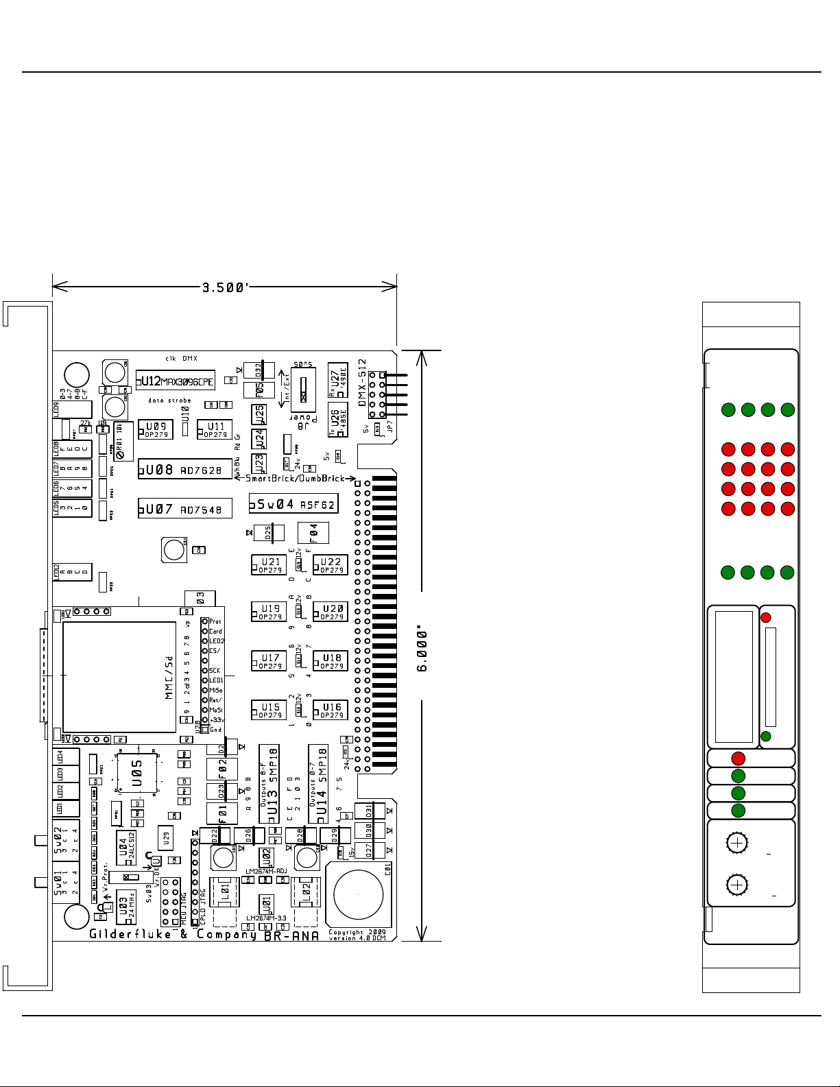
Br-ANA Panel Indicators
There are forty-six LED indicators on the front of the Br-ANA. They are used as fol-
lows:
A) Output Fuse Indicators
(Four Green LEDs)
These four LEDs are lit unless one of the four PTC fuses has been
tripped by an overload on the J6/A output cable.
B) Output Level Indicators
(Sixteen Red LEDs)
! These sixteen red LEDs show the output level on all sixteen of the 010 volt outputs. You will see these LEDs fade in and out as the signals on
the outputs change.
! Very low levels may not be indicated accurately on the LEDs:
a) If the negative reference is tied to ground, the LEDs will not
b) If the negative reference is not grounded, there may be a
C) J8 Input LEDs
(Four Green LEDs)
These LEDs indicate the status of the four optically isolated trigger inputs
on the Br-ANA. They are on the isolated side of the optoisolators. If they are
not on when you send a trigger to the Br-ANA, then there is an external wiring problem, the ʻinternal/externalʼ power switch needs to be changed for
your wiring setup, or the optoisolator has been damaged.
begin to glow until the output gets above about 1.75 volts.
slight glow even when the outputs are sending out a zero
voltage signal. There can also be a slight crosstalk in the
LEDs as their neighbors brighten and dim. This is only on the
indicators. The actual outputs do not cross talk.
D) Busy LED
(One Red LED)
Br-ANA Manual / December 18, 2012 10:21 AM / page 11 of 60
Page 12
Gilderfluke & Co.• 205 South Flower Street • Burbank, California 91502 • 818/840-9484 • 800/776-5972 • fax 818/840-9485
Board Error
Busy
Read
DMX-512
Running
Brain Heart/
Sd / Sd-HC
to Z-Bricks
Heartbeat
Address
Br-ANA
MSB
(
x0h)
0-3 4-7 8-B C-F
Fuse Status
LSB
(0
xh)
F E D C
B A 9 8
7 6 5 4
3 2 1 0
A B C D
Analog Outputs
J8 Inputs
C
4
08
E
26
A
D
F
1
B
9
7
5 3
C
4
08
E
26
A
D
F
1
B
9
7
5 3
This LED turns on when the Br-ANA is writing to the Sd card. The Sd
card, or power to the Br-ANA should not be removed if this LED is lit.
During firmware updates, the Read LED and Busy LED flash back and
forth. The first stage is comparing the BRANA400.FRM file on the Sd card. It
then flashes a little slower as it reads the BRANA400.FRM file in from the Sd
card. It then flashes back and forth much more quickly as it reprograms the
microcontroller in the Br-ANA. Under no circumstances remove power from
the Br-ANA while firmware is being updated. A partial firmware
update may ʻbrickʼ the BrANA, and then it will need
to be returned to the factory for reprogramming.
E)Read LEDs
(One green LED)
! This LED turns on when
the Br-ANA is reading data
from the Sd card. If you
have an AutoDownload file
stored on the Sd card, this
LED will be lit even when
no shows are running. This
is because there are always updates being made
on the outputs, even when
the shows are stopped.
! During firmware updates,
the Read LED and Busy
LED flash back and forth.
The first stage is comparing the BRANA400.FRM
file on the Sd card. It then
flashes a little slower as it
reads the BRANA400.FRM
file in from the Sd card. It
then flashes back and forth
much more quickly as it
Br-ANA Manual / December 18, 2012 10:21 AM / page 12 of 60
Page 13

Gilderfluke & Co.• 205 South Flower Street • Burbank, California 91502 • 818/840-9484 • 800/776-5972 • fax 818/840-9485
reprograms the microcontroller in the Br-ANA. Under no circumstances remove power from the Br-ANA while firmware is being updated. A partial
firmware update may ʻbrickʼ the Br-ANA, and then it will need to be returned
to the factory for reprogramming.
F) Board Error LED
(One Red LED)
This LED will flash when:
a) Br-ANA just booted (it stays on for a few seconds after booting
as a ʻlamp testʼ.
b) An error is found in the DMX-512 data checksum
c) An error is found in the 'Smart' Brick Network checksum
G) DMX-512 LED
(One Green LED)
This LED will be lit when the Br-ANA is receiving DMX-512 or RealTime
updates via the RS-422 serial port.
During AutoDownloads of show data to the Br-ANA, this LED will flash alternately with the Brain Heart/Running LED to show that a AutoDownload is
in process.
H) Brain Heart/Running LED
(One Green LED)
a) ʻSmartʼ Brick mode: The heartbeat from the 'Smart' Brick Brain is
transmitted throughout the system over the 'Smart' Brick Network.
The presence of a healthy heartbeat means that the data on the
'Smart' Brick Network is getting through cleanly. If it ever stutters
or flashes erratically (or not at all), then there is a problem with the
'Smart' Brick Brain, the 'Smart' Brick Network, or the Br-ANA. As
the DMX-512 takes precedence over the 'Smart' Brick Network,
this LED will go dark whenever a DMX-512 signal is present.
b) ʻDumbʼ Brick mode: This LED will be lit when the Br-ANA is run-
ning a show from its internal clock and Flash memory.
During AutoDownloads of show data to the Br-ANA, this LED will flash alternately with the DMX-512 LED to show that a AutoDownload is in process.
Br-ANA Manual / December 18, 2012 10:21 AM / page 13 of 60
Page 14

Gilderfluke & Co.• 205 South Flower Street • Burbank, California 91502 • 818/840-9484 • 800/776-5972 • fax 818/840-9485
I) Heartbeat LED
(One Blue LED)
a) This LED Flashes continuously while the CPU is running. If it
ever stops for more than a fraction of a second, the 'Deadman'
circuit in the Br-ANA will automatically reset the CPU. While performing an Ease-In, the heart rate will double.
Br-ANA Manual / December 18, 2012 10:21 AM / page 14 of 60
Page 15
IDS pin #
SIGNAL
1
Data bit 0
2
Data bit 1
3
Data bit 2
4
Data bit 3
5
Data bit 4
6
Data bit 5
7
Data bit 6
8
Data bit 7
9
Address bit 0
10
Address bit 1
11
Address bit 2
12
Address bit 3
13
Address bit 4
14
Address bit 5
15
Address bit 6
16
Address bit 7
17
ground
18
ground
19
Strobe/
20
Reset/
Gilderfluke & Co.• 205 South Flower Street • Burbank, California 91502 • 818/840-9484 • 800/776-5972 • fax 818/840-9485
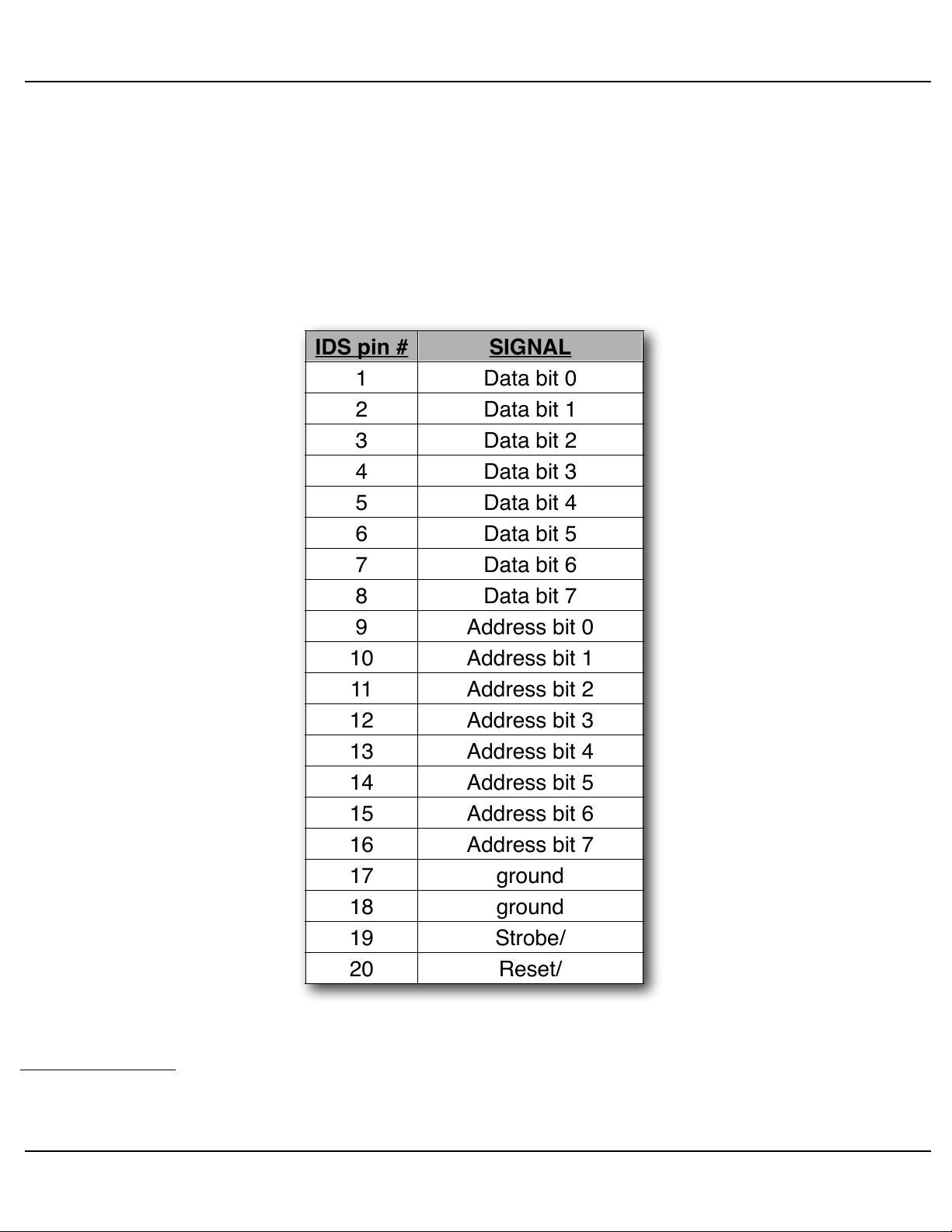
Br-ANA Connectors
A) Z-Brick
(One Twenty Pin IDS Header)
the Br-ANA outputs data from the DMX-512 input or onboard Flash Memory
to this connector. The format of the data is as follows:
3
This connector is used to control one or more Z-Bricks. When enabled,
When the address and data lines are valid, the rising edge of the Strobe
line will latch the data into the addressed outputs.
3
The Z-Brick connector is a legacy connection. It is there just for backwards-compatibility on existing systems. It is highly recommended that you do not use the Z-Brick connector for attaching Z-Bricks. Instead, just send DMX-512 to them just as you would for
any other GilderGear. The Z-Brick connector will likely not be installed unless specifically requested on new builds of Br-ANAs.
Br-ANA Manual / December 18, 2012 10:21 AM / page 15 of 60
Page 16

Gilderfluke & Co.• 205 South Flower Street • Burbank, California 91502 • 818/840-9484 • 800/776-5972 • fax 818/840-9485
B) Sd/SdHC Flash Memory Card Slot
(One Sd/SdHC compatible socket)
This socket is compatible with both standard Sd flash cards and SdHC
flash cards. It will support flash cards up to 32 GBytes in size. It will not currently support SdXC cards (64 GBytes and larger, as these require licensing
from Microsoft).
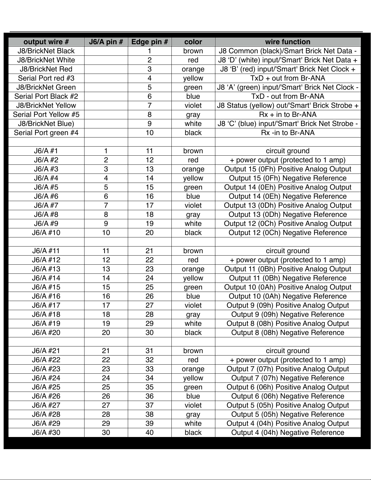
C) Backplane Connector
(60 Position Edge Connector)
The BackPlane connection is through a sixty position double sided edge
connector (thirty connections on each side on .1” centers). This is normally
plugged into a card cage which brings out all the backplane connections to
screw terminals, ribbon cable connectors, and other connectors. If needed,
an Insulation Displacement Edge (IDE) connector or other discrete edge
connector can be used to plug in the Br-ANA instead of one of our card
cages.
The first ten positions of the sixty position backplane connector are used
for the ʻSmartʼ Brick Network and J8 connection ('Smart' Brick Network or
optically isolated triggers, Depending on the position of Switch #4 the
ʻSmart/Dumb Brick Switchʼ) and RS-422 Serial Port. They are normally
bussed between all the cards in the card cage (although they can be separated by cutting the lines if desired). The card cages all bring the first ten positions of the 60 position backplane connector out to Rj-12/Rj-45 connectors.
The majority of connections are on the center forty pins of the backplane
connector. What these are used for depends on the type of card that is
plugged into the card cage slot. A Z-Brick or Br-MultiBrick32 uses them for
ʻJ6ʼ digital outputs. A Br-ANA uses these pins for its ʻJ6/Aʼ analog outputs. A
Br-ANA uses them for a combination of inputs and outputs. The card cages
bring out these forty connections to either a forty position screw terminal
block, a forty position ribbon cable connector, or both.
The last ten positions are used to provide power to the Br-ANA. These
wires are ganged to provide a higher current carrying capacity, and brought
out to screw terminals and/or 2.1mm power jacks on the card cages.
The pinout of the sixty position backplane connector is as follows:
Br-ANA Manual / December 18, 2012 10:21 AM / page 16 of 60
Page 17
output wire #
J6/A pin #
Edge pin #
color
wire function
J8/BrickNet Black
1
brown
J8 Common (black)/Smart Brick Net Data -
J8/BrickNet White
2
red
J8 ʻDʼ (white) input/'Smart' Brick Net Data +
J8/BrickNet Red
3
orange
J8 ʻBʼ (red) input/'Smart' Brick Net Clock +
Serial Port red #3
4
yellow
TxD + out from Br-ANA
J8/BrickNet Green
5
green
J8 ʻAʼ (green) input/'Smart' Brick Net Clock -
Serial Port Black #2
6
blue
TxD - out from Br-ANA
J8/BrickNet Yellow
7
violet
J8 Status (yellow) out/'Smart' Brick Strobe +
Serial Port Yellow #5
8
gray
Rx + in to Br-ANA
J8/BrickNet Blue)
9
white
J8 ʻCʼ (blue) input/'Smart' Brick Net Strobe -
Serial Port green #4
10
black
Rx -in to Br-ANA
J6/A #1
111brown
circuit ground
J6/A #2
212red
+ power output (protected to 1 amp)
J6/A #3
3
13
orange
Output 15 (0Fh) Positive Analog Output
J6/A #4
414yellow
Output 15 (0Fh) Negative Reference
J6/A #5
515green
Output 14 (0Eh) Positive Analog Output
J6/A #6
616blue
Output 14 (0Eh) Negative Reference
J6/A #7
717violet
Output 13 (0Dh) Positive Analog Output
J6/A #8
818gray
Output 13 (0Dh) Negative Reference
J6/A #9
919white
Output 12 (0Ch) Positive Analog Output
J6/A #10
10
20
black
Output 12 (0Ch) Negative Reference
J6/A #11
11
21
brown
circuit ground
J6/A #12
1222red
+ power output (protected to 1 amp)
J6/A #13
13
23
orange
Output 11 (0Bh) Positive Analog Output
J6/A #14
14
24
yellow
Output 11 (0Bh) Negative Reference
J6/A #15
15
25
green
Output 10 (0Ah) Positive Analog Output
J6/A #16
1626blue
Output 10 (0Ah) Negative Reference
J6/A #17
17
27
violet
Output 9 (09h) Positive Analog Output
J6/A #18
1828gray
Output 9 (09h) Negative Reference
J6/A #19
19
29
white
Output 8 (08h) Positive Analog Output
J6/A #20
20
30
black
Output 8 (08h) Negative Reference
J6/A #21
21
31
brown
circuit ground
J6/A #22
2232red
+ power output (protected to 1 amp)
J6/A #23
23
33
orange
Output 7 (07h) Positive Analog Output
J6/A #24
24
34
yellow
Output 7 (07h) Negative Reference
J6/A #25
25
35
green
Output 6 (06h) Positive Analog Output
J6/A #26
2636blue
Output 6 (06h) Negative Reference
J6/A #27
27
37
violet
Output 5 (05h) Positive Analog Output
J6/A #28
2838gray
Output 5 (05h) Negative Reference
J6/A #29
29
39
white
Output 4 (04h) Positive Analog Output
J6/A #30
30
40
black
Output 4 (04h) Negative Reference
Gilderfluke & Co.• 205 South Flower Street • Burbank, California 91502 • 818/840-9484 • 800/776-5972 • fax 818/840-9485
Br-ANA Manual / December 18, 2012 10:21 AM / page 17 of 60
Page 18
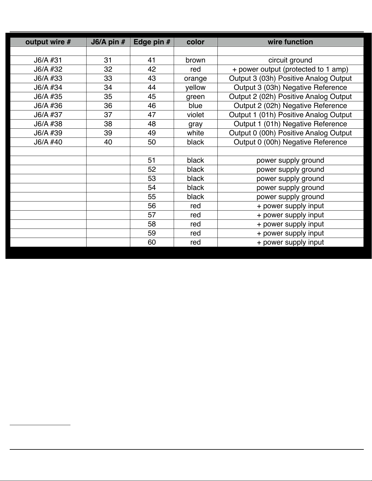
output wire #
J6/A pin #
Edge pin #
color
wire function
J6/A #31
31
41
brown
circuit ground
J6/A #32
3242red
+ power output (protected to 1 amp)
J6/A #33
33
43
orange
Output 3 (03h) Positive Analog Output
J6/A #34
34
44
yellow
Output 3 (03h) Negative Reference
J6/A #35
35
45
green
Output 2 (02h) Positive Analog Output
J6/A #36
3646blue
Output 2 (02h) Negative Reference
J6/A #37
37
47
violet
Output 1 (01h) Positive Analog Output
J6/A #38
3848gray
Output 1 (01h) Negative Reference
J6/A #39
39
49
white
Output 0 (00h) Positive Analog Output
J6/A #40
40
50
black
Output 0 (00h) Negative Reference
51
black
power supply ground
52
black
power supply ground
53
black
power supply ground
54
black
power supply ground
55
black
power supply ground
56
red
+ power supply input
57
red
+ power supply input
58
red
+ power supply input
59
red
+ power supply input
60
red
+ power supply input
Gilderfluke & Co.• 205 South Flower Street • Burbank, California 91502 • 818/840-9484 • 800/776-5972 • fax 818/840-9485
The card cages from Gilderfluke & Company are available in a variety of
sizes to hold between one to sixteen cards. Some of these card cages are
designed to be mounted in standard 19” electronics racks. Others are designed to be mounted standalone, on DIN rail or in Augat SnapTrak. The
smaller card cages bring out the center forty connections of the sixty position
backplane connector to either a forty position screw terminal block, a forty
position ribbon cable connector, or both. The Br-CC16 (sixteen slot) and BrCC09 (two slot) rack mounted card cages have only ribbon cable connectors
on them, but we have cc-BR16BO spring blocks that can mount directly to
the back of these card cages for attaching discrete wires. More commonly
the ribbon cables are run to a rail at the back of the rack or a nearby ʻbreak
out boxʼ, and c-40trans ribbon cable-to-screw terminal connectors are
mounted there allow discrete wires to be attached.
In all the animation systems made by Gilderfluke & Company, all Analog
input and output cabling is through what we call 'J6/A' standard output ribbon cables
4
Please note that the pinout of a J6 Digital output cable and a J6/A Analog output cable is completely different. Do not cross con-
nect any analog and digital cables. Damage can (and probably will) result.
4
. These are forty wire ribbon cables which are made up of four
Br-ANA Manual / December 18, 2012 10:21 AM / page 18 of 60
Page 19

Gilderfluke & Co.• 205 South Flower Street • Burbank, California 91502 • 818/840-9484 • 800/776-5972 • fax 818/840-9485
identical four channel wide cables of ten wire each. These split individual
cables called 1/4 J6/A. Each 1/4 J6/A also includes a common power supply
and ground wire which allow it to provide power for analog output accessories like Electronic FeedBack (EFB) controllers (these cards require a power
supply of 18 volts be used for the Br-ANA).
To simplify wiring to any MACs Animation Control System, the connectors
used on the J6/A cables are what are called 'insulation displacement connectors'. These simply snap on to an entire cable, automatically 'displacing'
the insulation and making contact with the wires within. This means that an
entire forty wire cable can be terminated in seconds. All connectors are polarized, to keep them from being plugged in backwards.
Analog loads are connected between each of the Positive outputs and its
associated Negative reference. The output capacity of each output is 50 ma.
The output voltage range can be adjusted from the Br-ANA to anywhere between 0 and 10 volts.
The negative reference is at a voltage of approximately 1.6 volts above
the circuit ground. The negative references are all connected on the Br-ANA,
but not to ground. On versions of the BS-ANA prior to 3.0, there could be no
direct connections made between any of the negative references and the
circuit grounds anywhere in the animation system. Starting with version 3.0
of the Br-ANA, connecting ground to the negative references is recommended unless you have an older EFB-Quad or PID-Quad that requires the
negative reference.
The '+ unregulated power output' for each 1/4 J6/A is protected by a solid
state circuit breaker (PTC Fuse) rated for 1 amp. You should treat each 1/4
J6/A as an individual, and not cross the outputs or power output lines from
one 1/4 J6/A to the lines from another. Doing this won't cause any damage,
but can reduce the protection for the outputs that the circuit breakers normally provide. The 'Output Fuse' LEDs on the front of the Br-ANA show the
condition of each of the PTC fuses. Each of these is a LED and resistor between the ground (pin #1 brown) wire and power output (pin #2 red) wire.
Each of these will be lit if the corresponding circuit breaker is OK. The resistor is 4.7 Kohms.
D) ʻSmartʼ Brick Network (on Card Cage)
(RJ-12 or RJ-45 Connector)
If Switch #4 is in the ʻSmartʼ Brick position, the Br-ANA will be operating
Br-ANA Manual / December 18, 2012 10:21 AM / page 19 of 60
Page 20

POSITION
WIRE #
COLOR
SIGNAL NAME:
LEFT
RIGHT
1
white
Smart Brick Net Data +
2
black
Smart Brick Net Data -
3
red
Smart Brick Net Clock +
4
green
Smart Brick Net Clock -
5
yellow
Smart Brick Net Strobe +
6
blue
Smart Brick Net Strobe -
Gilderfluke & Co.• 205 South Flower Street • Burbank, California 91502 • 818/840-9484 • 800/776-5972 • fax 818/840-9485
as a ʻSmartʼ Brick. The ʻSmartʼ Brick Network normally found on a ʻSmartʼ
Brick is brought out on the edge connector. When plugged into any
Gilderfluke & Co. Brick card cage, this will be brought out on a RJ-12 (or RJ-
5
45
) connector on the card cage. There should never be both ʻSmartʼ and
ʻDumbʼ Bricks in the same card cage. They share the same pins on the edge
connector and backplane. Damage may result if both are installed in the
same card cage.
The ʻSmartʼ Brick Network signals to the Br-ANA are brought in through a
six position RJ-12 (six position, six conductor modular telephone style connector) on the card cage. Facing either end of the cable with the release
latch upwards, its pin out is as follows:
E) ʻJ8ʼ Inputs (on Card Cage)
(RJ-12 or RJ-45 Connector)
If Switch #4 is in the ʻDumbʼ Brick position, the Br-ANA will be operating
as a ʻDumbʼ Brick. The trigger inputs and status output normally found on a
ʻDumbʼ Brick are brought out on the edge connector. When plugged into any
Gilderfluke & Co. Brick card cage, this will be brought out on a RJ-12 (or RJ-
6
45)
connector on the card cage. There should never be both ʻSmartʼ and
ʻDumbʼ Bricks in the same card cage. They share the same pins on the edge
connector and backplane. Damage may result if both are installed in the
same card cage.
5
If the card cage has a RJ-45 connector, just ignore the outer two wires. The center six wires are wired as shown for the RJ-12
connector.
6
If the card cage has a RJ-45 connector, just ignore the outer two wires. The center six wires are wired as shown for the RJ-12
connector.
Br-ANA Manual / December 18, 2012 10:21 AM / page 20 of 60
Page 21

POSITION
WIRE #
COLOR
SIGNAL NAME:
LEFT
RIGHT
1
white
Input ʻDʼ
2
black
Common
3
red
Input ʻBʼ
4
green
Input ʻBʼ
5
yellow
Status Out
6
blue
Input ʻCʼ
Gilderfluke & Co.• 205 South Flower Street • Burbank, California 91502 • 818/840-9484 • 800/776-5972 • fax 818/840-9485
There are four optically isolated digital inputs which can be used to start,
stop, pause or select specific show sequences to play. Facing the end of the
wire, with the latch upwards, the pinout of a standard ʻJ8ʼ cable is as follows:
Any event can be triggered on either the ʻclosingʼ or ʻopeningʼ edge of any
input. A ʻclosingʼ is when a current starts flowing out of an input. An ʻopeningʼ
is when that current stops. The inputs can be triggered on any voltage from
5 to 24 VDC. Although a battery is shown in the following drawing, you can
use any type of power supply.
Br-ANA Manual / December 18, 2012 10:21 AM / page 21 of 60
Page 22

Gilderfluke & Co.• 205 South Flower Street • Burbank, California 91502 • 818/840-9484 • 800/776-5972 • fax 818/840-9485
J8 with External Power
If you donʼt have an external source of power for these two inputs, you
can ʻstealʼ some juice from the Br-ANAʼs power supply connections by putting the ʻJ8 Powerʼ switch in the ʻInternalʼ position.
J8 with Internal Power
F) Power Supply (on Card Cage)
(Two Position Screw Terminals and/or 2.1mm Power Connector)
The last ten contacts of the Br-ANAʼs edge connector are used for the
power supply connections. The Br-ANA can be run from any supply voltage
from 17-24 VDC. Any lower than this and the card will not have the headroom when the outputs to reach all the way to 10 Volts. You can see the effects of a too low voltage power supply if the outputs do not reach all the
way to 10 volts, or have an excessive ripple in them when they get near to
10 volts.
This input is protected from reversed polarity. An idle Br-ANA draws only
about 150 milliamperes. The loads which the Br-ANA is controlling and the
LEDs on its face will usually draw far more current than the Br-ANA itself.
Br-ANA Manual / December 18, 2012 10:21 AM / page 22 of 60
Page 23

POSITION
WIRE #
COLOR
SIGNAL NAME:
LEFT
RIGHT
1
white
Signal Ground
2
black
- Serial data out from card
3
red
+ Serial data out from card
4
green
- Serial data in to card
5
yellow
+ Serial data in to card
6
blue
Ground
Gilderfluke & Co.• 205 South Flower Street • Burbank, California 91502 • 818/840-9484 • 800/776-5972 • fax 818/840-9485
G) RS-422 Serial Port (on Card Cage)
(RJ-12 or RJ-45 Connector)
This is used for configuration, uploading and downloading configurations,
status enquiries, AutoDownloading show data to Flash memory, and serial
port RealTime updates. It is compatible with all the RS-422 Serial Ports and
protocols used on Gilderfluke & Company products.
The four active lines on this connector are bussed to the backplane of the
card cage. This allows you to communicate to a whole card cage full of BrANAs, 'Smart' Brick Brains, Electronic FeedBack (EFB) 'Smart' Bricks and
other cards through the connector on the card cage. They just need to be
set to different addresses.
The serial data signals from the Br-ANA are brought out on a six position
RJ-12 (six position, six conductor modular telephone style connector) on the
card cage. Facing the end of the cable with the release latch upwards, its pin
out is as follows:
Computers donʼt normally come with serial ports on them anymore. Instead, you use a USB-to-Serial (USB-RS232/422
BlueTooth-to-Serial (Bt-Rs232Rx
(Modem-Internet
Br-ANA you will need one that provides a RS-422 connection, instead of the
more common RS-232. These are available from a number of different
sources, including Gilderfluke & Company. Our part number is USB-RS232/
422 for the USB-to-Serial adapter. It provides both RS-232 and RS-422 con-
nections.
The Br-ANA expects to see the serial data in the following format:
or C-USB-RS232) adapter,
and Bt-USBTx), Ethernet-to-Serial
) adapter, or WiFi-to-Serial (Modem-Wi-Fly) adapter. For the
Br-ANA Manual / December 18, 2012 10:21 AM / page 23 of 60
Page 24

Gilderfluke & Co.• 205 South Flower Street • Burbank, California 91502 • 818/840-9484 • 800/776-5972 • fax 818/840-9485
ONE START BIT
EIGHT DATA BITS
ONE STOP BIT
Br-ANA responds appropriately to all commands which are used by other
Gilderfluke & Co. serially controlled devices. These are used for configuration, uploading and downloading configurations, status enquiries, AutoDownloading show data to Flash memory, and serial port RealTime updates. It will
ignore all commands which are not addressed to it, or not appropriate for it
to respond to. This allows it to share the same RS-422 serial buss with additional Br-ANAs, Digital Audio Repeaters, 'Smart' Brick Brains and any other
serially controlled devices. The only requirement is that each unit be addressed to a unique serial address. On the Br-ANA, the serial address is set
using the two rotary switches on its front.
H) DMX-512 Data In/Out (on Card Cage)
(Ten pin Male header on Br-ANA)
(Five Position Screw Terminal)
DMX-512 is received through the ten pin male header on the Br-ANA.
The card cage will route this from the five position screw terminal(s) on the
card cage. This is identical to the DMX-512 reception on all other Gilderfluke
& Company card cage mounted controllers.
The Br-ANA will stop listening to the 'Smart' Brick network and stop playing shows from the onboard Sd card memory whenever there is a DMX-512
signal present on this input. The DMX-512 input takes precedence over all
other connections on the Br-ANA.
The DMX-512 standard was developed by the United States Institute for
Theatrical Technology (USITT) for a high speed (250 KBaud) asynchronous
serial data link. Although it was originally designed for controlling light dimmers, it is now supported by hundreds of suppliers throughout the world for
controlling all kinds of theatrical equipment.
All of the equipment on the DMX-512 network can be in one cabinet or
control room, but are more commonly distributed throughout the installation.
This allows the individual controllers to be prewired to whatever they are
controlling and completely pretested before the installation even starts. During installation, instead of running hundreds (or thousands) of wires to each
control point, a single DMX-512 network is daisy-chained through each local
controller.
Br-ANA Manual / December 18, 2012 10:21 AM / page 24 of 60
Page 25

Manufacturer
Part #
Gauge
Wire Stranding
Belden
3105A
22 AWG
7 x 30
Belden
3106A
22 AWG
7 x 30
Belden
9841
24 AWG
7 x 32
Belden
7200A
24 AWG
41 x 40 (high flexibility)
Proplex
PC222P
22 AWG
19 x 34
Dataplex
WDP222TBK
22 AWG
16 x 0.2mm
Gilderfluke & Co.• 205 South Flower Street • Burbank, California 91502 • 818/840-9484 • 800/776-5972 • fax 818/840-9485
A DMX-512 network can be as long as a mile, or as short as a few
inches. The DMX-512 network needs to be one long line, with no long side
branches. If the network is longer than a few feet, you may need to provide a
terminating resistor at the two far ends of the network (120Ω, ½ Watt is typically used). The resistors suppress ʻechosʼ on the DMX-512 wires.
If the network runs throughout a facility, it is prudent to use a some isolated splitters. These will keep an electrostatic zap or lightning hit on the
network from damaging the entire network. An isolated splitter also allows
you to run side branches on the network, since each isolated branch is
treated as a separate DMX-512 network (daisy chained from DMX-512
ʻSlaveʼ to ʻSlaveʼ, it can be run up to a mile, and may need its own termination resistors).
Addresses 256 and 257 are optionally used in GilderGear for transmitting
a checksum. The Br-ANA can use this to verify that the data received from
PC•MACs has no transmission errors in it. If you address a light dimmer or
other DMX-512 device to addresses 256 or 257, you will see this verification
data displayed as a flickering pattern. Most GilderGear will automatically
start requiring GilderChecksums after receiving DMX-512 that has GilderChecksums in it. Once it starts requiring GilderChecksums, the only way to
get the Br-ANA to stop requiring it is to cycle power on the Br-ANA.
Note that at higher frame rates, not all 512 channels can be transmitted
through DMX-512. This is why it is unusual to run shows over 30 FPS.
The typical wires used for carrying a DMX-512 network are a single
shielded twisted pair or wires. For short runs, just about any ʻmicrophone
cableʼ can be used. For longer runs, a low capacitance twisted pair is recommended. Recommended wires include:
Br-ANA Manual / December 18, 2012 10:21 AM / page 25 of 60
Page 26

Pair
Wire #
Color
Function
DMX-512 Pin
Pair 2
1
White / Orange
Data 1+
DMX-512 Pin 3
2
Orange
Data 1-
DMX-512 Pin 2
Pair 3
3
White / Green
no connection
no connection
6
Green
Pair 1
4
Blue
5
White / Blue
Pair 4
7
White / Brown
Signal Common
DMX-512 Pin 1
8
Brown
Shield
Drain
Gilderfluke & Co.• 205 South Flower Street • Burbank, California 91502 • 818/840-9484 • 800/776-5972 • fax 818/840-9485
Recent revisions of the DMX-512 standards have included specifications
for running raw DMX-512 signals through standard Cat-5 (or better) ethernet
cables. The recommended pinout is as follows:
The DMX-512 standard calls out a 5 pin XLR connector or screw terminals for all connections. All card cages will provide either screw terminals or
other appropriate connection for attaching the DMX-512 input and output.
Br-ANA Manual / December 18, 2012 10:21 AM / page 26 of 60
Page 27

Gilderfluke & Co.• 205 South Flower Street • Burbank, California 91502 • 818/840-9484 • 800/776-5972 • fax 818/840-9485
Br-ANA Hardware Configuration
There are only a hand full of switches and a single trimpot which can be used to configure the Br-ANA. Once these are set, you will probably never need to adjust them
again. Most of the configuration is done through the Software Configuration, which is
described in the following section.
A) Address
(Two Rotary Switches)
These two rotary switches on the front of the Br-ANA are used to set the
DMX-512 address for the outputs and the location on the RS-422 serial port
where this card will be found. Normally, only one Br-ANA (or other) card is
set to use any one address. If more than one card is set to the same address, then the serial ports cannot be attached to the same RS-422 multidrop network at the same time. Overlapping addresses wonʼt cause any
damage, but you will get garbled data as both cards try to respond to the
same configuration commands.
If no AutoDownload file has been sent to the Br-ANA, then the Br-ANA
will default to using the address set by these switches as the DMX-512/
Serial RealTime address for the outputs as well as the RS-422 serial address. Normally the DMX-512/Serial RealTime address of the outputs is set
by the AutoDownload file which has been sent to the card.
An option under the configuration menu allows you to choose these
switches, the address found in the AutoDownload file, or an arbitrary address you set for the address of the first output of the Br-ANA.
The RS-422 serial address for the Br-ANA is set using Hexadecimal
numbers on these switches. The first digit of the Hexadecimal address is set
on the upper of the two switches. The second digit of the hexadecimal address is set on the lower of the two switches. If you are not sure how these
translate from decimal numbers, a chart at the end of every Gilderfluke &
Company manual will show you the equivalent numbers.
B) Write Protect Switch
(Slide Switch)
When this switch is ʻWrite Protectʼ position, the Br-ANA will protect the
onboard flash memory and configuration EEprom from accidental altera-
Br-ANA Manual / December 18, 2012 10:21 AM / page 27 of 60
Page 28

Gilderfluke & Co.• 205 South Flower Street • Burbank, California 91502 • 818/840-9484 • 800/776-5972 • fax 818/840-9485
tions. With the switch in the ʻWrite OKʼ position, reads and writes can take
place normally. This switch must be in the ʻWrite OKʼ position for shows to
be downloaded via the serial port to the Br-ANA. With the memory write protected, the Br-ANA should retain whatever has been programmed into it for
at least forty years.
C) Smart' Brick/'Dumb' Brick Select
(Slide Switch)
This switch tells the Br-ANA whether the Br-ANA is going to be acting like
a ʻDumbʼ Brick or a ʻ'Smart' Brickʼ. When acting as a ʻDumbʼ Brick, the BrANA will be triggered to play shows by the four optically isolated ʻJ8ʼ trigger
inputs. When acting as a ʻSmartʼ Brick, The Br-ANA will lock to and follow
time code information send to it through the 'Smart' Brick Network from the
'Smart' Brick Brian.
A single card cage should not have both ʻSmartʼ and ʻDumbʼ Bricks installed in the same card cage. Damage may result if there are.
of the Br-ANA between the optoisolators used for 'Dumb' Bricks and the RS422 receivers used for 'Smart' Bricks. If you plug a Br-ANA which has been
configured to act as a 'Smart' Brick into a slot that has been configured for a
'Dumb' Brick, you risk damaging the RS-422 receivers.
'Smart' Brick until it receives a valid message through the 'Smart' Brick
Network. In the unlikely event that you switch from 'Smart' Brick to 'Dumb'
Brick mode while a Br-ANA is running, there will be a delay of ten seconds
or so before it starts acting as a 'Dumb' Brick.
D) J8 Power
(Slide Switch)
whether the ʻJ8ʼ power for the optoisolators is provided by the same power
supply as the Br-ANA, or is provided by an external isolated source. When
operating as a 'Smart' Brick, this switch has no effect. See the ʻJ8ʼ instruc
tions
This switch actually switches the six wires that connect to the backplane
The Br-ANA doesnʼt actually believe that it has been set to act as a
If the Br-ANA is acting as a 'Dumb' Brick, then this switch is used to select
-
for more details on this.
Br-ANA Manual / December 18, 2012 10:21 AM / page 28 of 60
Page 29

Gilderfluke & Co.• 205 South Flower Street • Burbank, California 91502 • 818/840-9484 • 800/776-5972 • fax 818/840-9485
E) Full Scale Adjust
(Ten Turn Trimpot)
The ten turn pot R1 is the one adjustment on the Br-ANA. It sets the gain
for the Digital to Analog (D/A) converters on the board. It is set at the factory,
and should never need any adjustment after that. To set it, pick any output
and set the minimum and maximum scaling to their minimums and maximums through the configuration screen. When you send a full scale output
command to this output, you should then be able to adjust it for 10.00 volts
using The 10 turn pot R1. The adjustments for the endpoints on each of the
sixteen outputs are individually set through the setup screen.
Br-ANA Manual / December 18, 2012 10:21 AM / page 29 of 60
Page 30

Gilderfluke & Co.• 205 South Flower Street • Burbank, California 91502 • 818/840-9484 • 800/776-5972 • fax 818/840-9485
this page is not blank
Br-ANA Manual / December 18, 2012 10:21 AM / page 30 of 60
Page 31

Gilderfluke & Co.• 205 South Flower Street • Burbank, California 91502 • 818/840-9484 • 800/776-5972 • fax 818/840-9485
Br-ANA Software Configuration
The Br-ANA can be accessed through the serial port from any computer running just
about any modem or terminal program. We provide a free terminal program called GilderTerm that makes working with GilderGear through the serial port a little easier. The
computer you are using doesnʼt even need to have any PC•MACs software installed on
it.
Most Gilderfluke & Co products can be controlled through their RS-232 or RS-422
Serial ports. The Br-ANA has a single RS-422 serial port on it. Up to 256 different cards
and devices can be attached to the same serial lines, to form a complete RS-422 ʻmulti
Dropʼ network. Anywhere on this network you can attach operator panels to access and
control it, or you can use an WiFi or Ethernet modem so that it can be accessed from
around the block or around the world. Commands can be addressed to a single card on
the network, or all the cards simultaneously.
If you donʼt have access to GilderTerm, typical modem programs you can use are
Terminal.exe (which came with Windows 3.1) and HyperTerm.exe (which comes with
later versions of Windows). The terminal program must support VT-52 commands to position the cursor and clear the screen.
GilderTerm is available free from Gilderfluke & Co. for use with all of our products. It
can be downloaded from our web page, and is included on all of our CD-ROMs. GilderTerm has been optimized for use with all Gilderfluke & Company equipment. All the
commands are built in, and it will even let you use your mouse to select commands by
clicking on the menus.
If you are using GilderTerm, all the settings are fixed at the appropriate settings. All
you will need to do is select the appropriate ʻCOMʼ port. To talk to the Br-ANA, just configure your terminal program for 9600 baud, no parity, eight data bits, one stop bit and
no flow control handshaking.
Computers donʼt normally come with serial ports on them anymore. Instead, you use
a USB-to-Serial (USB-RS232/422
Rs232Rx and Bt-USBTx), Ethernet-to-Serial (Modem-Internet) adapter, or WiFi-to-Serial
(Modem-Wi-Fly
connection, instead of the more common RS-232. These are available from a number of
different sources, including Gilderfluke & Company. Our part number is USB-RS232/422
for the USB-to-Serial adapter. It provides both RS-232 and RS-422 connections.
If not using GilderTerm, your terminal emulation program must support VT-52 terminal emulation to do cursor positioning, clearing the screen, and a handful of other functions. You should set your program NOT to insert an extra LineFeed (LF) character after
) adapter. For the Br-ANA you will need one that provides a RS-422
or C-USB-RS232) adapter, BlueTooth-to-Serial (Bt-
Br-ANA Manual / December 18, 2012 10:21 AM / page 31 of 60
Page 32

POSITION
WIRE #
COLOR
SIGNAL NAME:
LEFT
RIGHT
1
white
Signal Ground
2
black
Rx- data in to Converter
3
red
Rx+ data in to Converter
4
green
Tx- data out of Converter
5
yellow
Tx+ data out of Converter
6
blue
Ground
Gilderfluke & Co.• 205 South Flower Street • Burbank, California 91502 • 818/840-9484 • 800/776-5972 • fax 818/840-9485
each Carriage Return (CR) it receives. You should also tell it NOT to scroll automatically
after the eightieth column is filled. If either of these are on, the screen will be displayed
'double spaced'. This won't cause any problem, but will make it hard to see the whole
screen at one time.
If you have hooked up the Br-ANA to your computer and it still doesn't seem to respond to the keyboard, the first thing to check is that you are attached to the right serial
port. The easiest way to do this is to disconnect the Br-ANA and short between the Tx
data out and Rx data in pins on your USB-to-Serial converter. For a RS-422 port, this
means temporarily shorting the Rx+ to the Tx+, and Rx- to the Tx-, so two jumpers will
be needed. On the USB-Rs232/422, the pinout is as follows:
While still running the modem program, anything you type should be shown on the
screen while these jumpers are in place, while nothing will appear when you remove
them. If your computer passes this test, then you are using the right serial port and the
problem is most likely the baud rate setting or in your wiring to the Br-ANA. If you get
characters on the screen even with the jumpers removed from the serial port, it means
you probably need to set the 'echo' mode to 'none' or 'full duplex' and try this test again.
To enter the configuration mode you need to press the ʻconfigureʼ button on GilderTerm, or type the following if you are not using GilderTerm. The (address) is replaced
by the HEX value set on the ADDRESS switches on the front of the Br-ANA:
m5AA5(address)
If any other card is in configuration mode (or even if it just thinks another card is in
configuration), the Br-ANA won't be able to enter configuration mode. To exit any other
card from configuration type 'XN'. You can then try entering configuration again.
For eight bit resolution outputs, the menu will appear as follows. Decimal values have
been selected for the numbers. At the top of the screen the size of the Animation Data
Br-ANA Manual / December 18, 2012 10:21 AM / page 32 of 60
Page 33

Gilderfluke & Co., Inc. - BR-ANA Analog Card - version 4.10 - copyright 2012 DCM
Shows: 8, Ch: 123 @___0, ADL: AutoDownload_Filename
Serial Address- __0
__1 Show_FileName.sho looping @ frame ____1363
inputs: a/green: Y | b/red: Y MSB E minimum maximum "forced" PowerOn
c/blue: Y | d/white: Y address I scale scale position default
a) 1st addr: __0 (Autodownload) 0 (0) |_|____0__|__255__|_______|____0__|
b) twelve bit resolution- no -> 1 (1) |Y|____0__|__255__|_______|____0__|
c) sequencer enabled- yes 2 (2) |Y|____0__|__255__|_______|____0__|
d) DMX: Tx & Rx wo/CS, ^d) 1-based 3 (3) |Y|____0__|__255__|_______|____0__|
e) auto EaseIn- 1.00 seconds 4 (4) |Y|____0__|__255__|_______|____0__|
f) numbering- decimal/millisecond 5 (5) |_|____0__|__255__|_______|____0__|
6 (6) |_|____0__|__255__|_______|____0__|
j) address to test & adjust- __1 7 (7) |Y|____0__|__255__|_______|____0__|
k) test output- none 8 (8) |Y|____0__|__255__|_______|____0__|
FigureName 9 (9) |Y|____0__|__255__|_______|____0__|
OutputName 10 (A) |Y|____0__|__255__|_______|____0__|
11 (B) |Y|____0__|__255__|_______|____0__|
u) set min/max/forced using keypad 12 (C) |Y|____0__|__255__|_______|____0__|
q) force output to a value 13 (D) |_|____0__|__255__|_______|____0__|
t) set PowerOn defaults 14 (E) |_|____0__|__255__|_______|____0__|
w) set analog endpoints 15 (F) |_|____0__|__255__|_______|____0__|
n) Next, l) Last, i) info, o) def., p) looP, h) Halt, r) save, v) Verify, x) Xit
Command-
Gilderfluke & Co.• 205 South Flower Street • Burbank, California 91502 • 818/840-9484 • 800/776-5972 • fax 818/840-9485
Flash Memory installed (if any) is shown. If the Animation Data Flash Memory isn't
found, then 'not found' will appear in this space at the top of the screen.
To redraw the screen at any time, just press the <ESC>ape key or <SPACE> bar.
All numeric values are entered in HEXadecimal (0-9, A through F) or Decimal numbers (0-9), as selected on the menu. Each number consist of one or more ASCII characters followed by a <RETURN> (<ENTER> on some keyboards). If more characters have
been entered before the <RETURN> than are allowed, then the characters already entered will scroll to the left to make room for the new entries. Once a command has been
invoked, characters can be erased one-by-one by using the <DELETE> key (<BACKSPACE> on some keyboards). An entire entry can be erased by hitting the <ESC>ape
key. A command can be canceled altogether by hitting the <RETURN> key (<ENTER>
on some keyboards) or <ESC>ape key after all the characters have been erased or before any have been entered.
Once you have configured a Br-ANA, you can ʻlockʼ the configuration by moving the
ʻWrite Protectʼ switch to the ʻWrite Protectedʼ position from the ʻWrite Enabledʼ position.
This should protect your configuration from anything short of a lightning hit. The menu
will change to show that the Flash Memory has been protected and warn you that you
Br-ANA Manual / December 18, 2012 10:21 AM / page 33 of 60
Page 34

Gilderfluke & Co.• 205 South Flower Street • Burbank, California 91502 • 818/840-9484 • 800/776-5972 • fax 818/840-9485
can no longer make any changes. Configuration changes can be re-enabled at any time
by moving the switch back to the ʻEnabledʼ position.
If you want to keep a hard copy printout of the current configuration of the Br-ANA,
you should use the <ESC>ape key to redraw the screen while ʻsaving to fileʼ in the modem program running on your computer. This file can be printed out at any time, or
spliced into the documentation package for your project.
A) First Address:
The front panel switches are always used for the RS-422 Serial Port Ad-
dress. This toggle selects whether the outputsʼ address is set from:
1) Address stored in the AutoDownload file. This is the Default.
2) Address from the Serial Port Address switches on the front of
the Br-ANA. This is the default if no AutoDownload file is
loaded.
3) Addressed at a location you specify.
If twelve bit resolution has been selected, then any ʻillegalʼ
dress will be skipped.
B) Twelve Bit Resolution:
If using a v1.1 AutoDownload file generated with Pc•MACs version
2.02.212.xxx or later, this will be set automatically for you from data in the
AutoDownload file.
When toggled ON, the output resolution will be twelve bits. This works out
to a resolution of one part in 4096. With a 0-10 volt output, each step will be
.00244 volts. If you are using 12 bit resolution analogs, you must carefully
account for the locations and number of output channels you are using.
Each 12 bit resolution input takes 1-1/2 eight bit channels. The Br-ANA wonʼt
let you set the first address for a 12 bit analog channel to any address that
can be evenly divided by three (0, 3, 6, 9, etc.). This is because it uses these
bytes for storing the least significant four bits of the next two 12 bit resolution
channels. Any 12 bit resolution channel that is addressed at an address that
can be divided evenly by three plus one (addresses 1, 4, 7, 10, etc.) will
need to have the previous address sent (or burnt into the Flash Memory) so
that its lowest four bit nibble isnʼt lobbed off. Any 12 bit resolution channel
that is addressed at an address that can be divided evenly by three plus two
7
twelve bit ad-
7
A twelve bit value cannot be addressed at any address that can evenly be divided by three (0, 3, 6, etc.).
Br-ANA Manual / December 18, 2012 10:21 AM / page 34 of 60
Page 35

Gilderfluke & Co.• 205 South Flower Street • Burbank, California 91502 • 818/840-9484 • 800/776-5972 • fax 818/840-9485
(addresses 2, 5, 8, 11, etc.) will need to have the previous two addresses
sent (or burnt into the Flash Memory) so that its lowest four bit nibble isnʼt
lobbed off.
C) Sequencer Enabled:
This toggle enables and disables the Br-ANA to use the Animation Data
Flash Memory. When it is OFF, nothing will be output from the AutoDownload file stored on the micro Sd/SdHC flash card. Any output data must
come from either the DMX-512 or Serial Port inputs. If it is ON, then the data
from the AutoDownload file on the micro Sd/SdHC flash card will be sent
out.
D) DMX-512 mode:
If using a v1.1 AutoDownload file generated with Pc•MACs version
2.02.212.xxx or later, this will be set automatically for you from data in the
AutoDownload file.
If there isnʼt a v1.1 AutoDownload file being used, this command is a toggle which can be used to enable and disable the DMX-512 reception and
transmission, as well as the GilderChecksums.
The GilderChecksums allow GilderGear to recognize errors in DMX-512
data. With GilderChecksums, the outputs wonʼt be updated when a bad data
packet is received. GilderChecksums should be left ON whenever sending
DMX-512 to other GilderGear.
The Br-ANA, and most other GilderGear will automatically sense when it
is receiving GilderCheckSums. Once it does this, the GilderGear will have to
be reset before it will accept DMX-512 data without GilderCheckSums.
^d) DMX-512 Zero-Based or One-Based:
If using a v1.1 AutoDownload file generated with Pc•MACs version
2.02.212.xxx or later, this will be set automatically for you from data in the
AutoDownload file.
If there isnʼt a v1.1 AutoDownload file being used, this command is a toggle between displaying DMX-512 addresses as 0-511 numbers, or as 1-512
numbers.
Br-ANA Manual / December 18, 2012 10:21 AM / page 35 of 60
Page 36

Gilderfluke & Co.• 205 South Flower Street • Burbank, California 91502 • 818/840-9484 • 800/776-5972 • fax 818/840-9485
E) Auto Ease-In:
If using a v1.1 AutoDownload file generated with Pc•MACs version
2.02.212.xxx or later, this will be set automatically for you from data in the
AutoDownload file.
When enabled, this feature will keep all the selected channels from jump-
ing at a high rate of speed if:
1) Incoming frame number received through the 'Smart' BrickNet
jumps more than five frames. (This is typically caused by discontinuous time code being received by the 'Smart' Brick Brain,
or when the 'Smart' Brick Brain jumps to a different show.)
2) The DMX-512 data starts being received.
3) The DMX-512 signal drops out for more than a second.
4) An output is forced to a specific value.
5) One or more outputs are put into or taken out of the internal
test mode.
6) At boot up as the outputs assume their default values.
This command allows you to select the amount of time any output will
take to ramp from one extreme to the other and which outputs will be using
the Ease-In feature. The range of time available is:
1) Ease-In is disabled
2) ¼ second
3) ½ second
4) ¾ second
5) 1 second
6) 1-½ seconds
7) 2 seconds
8) 2-½ seconds
9) 3 seconds
10) 4 seconds
11) 5 seconds
12) 6 seconds
13) 7 seconds
14) 8 seconds
15) 9 seconds
16) 10 seconds
Br-ANA Manual / December 18, 2012 10:21 AM / page 36 of 60
Page 37

Gilderfluke & Co.• 205 South Flower Street • Burbank, California 91502 • 818/840-9484 • 800/776-5972 • fax 818/840-9485
You can tell when an Ease-In is being performed by the Heartbeat jumping to a speed twice normal. Once all outputs have dropped out of Ease-In
mode, the heartbeat will return to its regular rate.
Which outputs have been set to use the Ease-In Feature is shown under
the column labeled ʻEIʼ. Outputs which will be Eased In are shown by the letter ʻYʼ. All other channels will be unaffected by the Ease-In.
The Ease-In only affects the sixteen on-board analog outputs from the BrANA. All the data output on DMX-512 or Z-Buss port to the Z-Bricks are unaffected.
F) Numbering System:
This toggle is used to select between HEXadecimal, Decimal or percentage numbering systems for display and entries. When the Br-ANA prompts
you for a numeric entry, you will need to enter a HEXadecimal or Decimal
number, depending on this setting.
J) Output to Test & Adjust:
This command is used to set the output address that will be used by the
'Test Output', 'Set Analog Endpoints', 'Force output to a Value', ʻset Min/Max/
forced using keypadʼ, and 'set PowerOn Defaults' commands. If the output
address selected is one of the sixteen on the Br-ANA, then an arrow will appear to the left of it on the screen. In the eight bit resolution example screen
above you can see this arrow pointing to output #1, which happens to be
addressed at address ʻ001ʼ. Since some of the adjustments can affect channels that are only transmitted through the DMX-512 and Z-Brick outputs, the
address can be set to anywhere between 0 and 511 (or 1-512).
If the AutoDownload file is a v1.1 or later, the FigureName and OutputName will be displayed just below the ʻTest Outputʼ command.
K) Test Output:
When toggled to ʻTest One Outputʼ, the single output selected by the
'Output to Test & Adjust' command will be ramped up and down. The ramp
time is about 5 seconds. The time the output dwells at each extreme is
about one second.
When pressed a second time, this command will toggle to ʻTest All Outputsʼ. All the outputs will be ramped between their two extremes. The ramp
Br-ANA Manual / December 18, 2012 10:21 AM / page 37 of 60
Page 38

Gilderfluke & Co., Inc. - BR-ANA Analog Card - version 4.10 - copyright 2012 DCM
Shows: 8, Ch: 123 @___0, ADL: AutoDownload_Filename
Serial Address- __0
__1 Show_FileName.sho looping @ frame ____1363
inputs: a/green: Y | b/red: Y MSB E minimum maximum "forced" PowerOn
c/blue: Y | d/white: Y address I scale scale position default
minimum maximum "forced" 0 (0) |_|____0__|__255__|_______|____0__|
adjust--> scale scale position-> 1 (1) |_|____0__|__255__|_______|____0__|
|-----------------------| 2 (2) |_|____0__|__255__|_______|____0__|
Up--> | 7 | 8 | 9 | 3 (3) |_|____0__|__255__|_______|____0__|
|-----------------------| 4 (4) |_|____0__|__255__|_______|____0__|
middle--> | 4 | 5 | 6 | 5 (5) |_|____0__|__255__|_______|____0__|
|-----------------------| 6 (6) |_|____0__|__255__|_______|____0__|
Down--> | 1 | 2 | 3 | 7 (7) |_|____0__|__255__|_______|____0__|
|-----------------------| 8 (8) |_|____0__|__255__|_______|____0__|
9 (9) |_|____0__|__255__|_______|____0__|
10 (A) |_|____0__|__255__|_______|____0__|
11 (B) |_|____0__|__255__|_______|____0__|
a) toggle Auto force to 0% or 100% 12 (C) |_|____0__|__255__|_______|____0__|
1, 4, 7, -) sets "forced" to 0% 13 (D) |_|____0__|__255__|_______|____0__|
2, 5, 8, +) sets "forced" to 100% 14 (E) |_|____0__|__255__|_______|____0__|
Hit <CR> to save, <Esc> to bail out 15 (F) |_|____0__|__255__|_______|____0__|
n) Next, l) Last, i) info, o) def., p) looP, h) Halt, r) save, v) Verify, x) Xit
Command-
Gilderfluke & Co.• 205 South Flower Street • Burbank, California 91502 • 818/840-9484 • 800/776-5972 • fax 818/840-9485
time is still about 5 seconds. The time the output dwells at each extreme is
about one second.
U) Set Minimum, Maximum and Forced using Keypad:
This is the easiest way to adjust the endpoints of the analog outputs to
prevent a mechanical movement from over traveling. The normal range of
the outputs is 0 to 10 volts DC. If your analog movement is hitting the ends
of travel, you can reduce this range until it doesnʼt hit the mechanical ends of
travel.
Selecting his command redraws the left side of the screen. The drawing
shows the numeric keypad found on most keyboards. The ʻarrowʼ points to
the output which has been selected. You can select a different output by
pressing the ʻN) Nextʼ or ʻL) Lastʼ commands.
Use the ʻ1ʼ, ʻ4ʼ and ʻ7ʼ keys to adjust the ʻminimumʼ position the for the se-
lected analog output. This sets the voltage that will be sent out from the BrANA when you give it a ʻzeroʼ position command through the DMX-512 or
AutoDownload file. The default analog output (when set to 0/0h) is 0 vdc.
Br-ANA Manual / December 18, 2012 10:21 AM / page 38 of 60
Page 39

Gilderfluke & Co.• 205 South Flower Street • Burbank, California 91502 • 818/840-9484 • 800/776-5972 • fax 818/840-9485
This will automatically force the output to the ʻzeroʼ position 8. For cylinders
and electric actuators, this is usually the fully retracted position. You can adjust the analog output to anywhere between 0 and 10 volts. If you adjust the
ʻminimumʼ to a voltage that is higher than the ʻmaximumʼ, this is perfectly ac-
ceptable, and is the easiest way to reverse the motion of an actuator.
The keys are used as follows:
1) decrements the ʻminimumʼ position value
4) sets the ʻminimumʼ position value to 128 (50%)
7) increments the ʻminimumʼ position value
Use the ʻ2ʼ, ʻ5ʼ and ʻ8ʼ keys to adjust the ʻmaximumʼ position the for the
selected analog output. This sets the voltage that will be sent out from the
Br-ANA when you give it a ʻ100%ʼ position command through the DMX-512
or AutoDownload file. The default analog output (when set to 255/0FFh) is
10 vdc. This will automatically force the output to the ʻ100%ʼ position
9
. For
cylinders and electric actuators, this is usually the fully extended position.
You can adjust the analog output to anywhere between 0 and 10 volts. If you
adjust the ʻmaximumʼ to a voltage that is lower than the ʻminimumʼ, this is
perfectly acceptable, and is the easiest way to reverse the motion of an actuator.
The keys are used as follows:
2) decrements the ʻmaximumʼ position value
5) sets the ʻmaximumʼ position value to 128 (50%)
8) increments the ʻmaximumʼ position value
You can then use the ʻ-ʼ, ʻ+ʼ, ʻ3ʼ, ʻ6ʼ and ʻ9ʼ keys to move the analog output
over the full range of output (the full range is set by the values in the ʻminimumʼ and ʻmaximumʼ columns). You can use these keys to test your adjustments. The Br-ANA does this by using these keys to adjust the ʻforcedʼ
value. When you are done adjusting this output, you will want to make sure
you clear the ʻforcedʼ value, or the analog output will remain locked at the
last value set in the ʻforcedʼ column. You can do this by hitting the ʻ-ʼ key
twice, or hitting the ʻ3ʼ (decrement forced value) one more time after it is already at zero.
8
This ʻforcingʼ feature can be toggled on and off using the command ʻa) toggle Auto force to 0% or 100%ʼ, or if you entered this
mode while holding down the <control> key while you pressed the ʻuʼ key.
9
This ʻforcingʼ feature can be toggled on and off using the command ʻa) toggle Auto force to 0% or 100%ʼ, or if you entered this
mode while holding down the <control> key while you pressed the ʻuʼ key.
Br-ANA Manual / December 18, 2012 10:21 AM / page 39 of 60
Page 40

Gilderfluke & Co.• 205 South Flower Street • Burbank, California 91502 • 818/840-9484 • 800/776-5972 • fax 818/840-9485
If you have console or other way of moving the channel you are adjusting,
you will probably not use this feature and use the console instead.
The keys are used as follows:
ʻ-ʼ)!sets the ʻforcedʼ position value to zero (a 2nd time clears ʻforcedʼ)
ʻ+ʼ or ʻ=ʼ)!sets the ʻforcedʼ position value to 100%
2) decrements the ʻforcedʼ position value
5) sets the ʻforcedʼ position value to 128 (50%)
8) increments the ʻforcedʼ position value
When you are satisfied with your adjustments, just hit the <Carriage Return>. If you donʼt want to save your settings, hit the <ESC>ape key to restore the original values.
Q) Force Outputs to a Value:
This command is used to force an output to any value. This value can be
written into EEprom Memory so that the output will never leave this value,
even after the Br-ANA is reset. It can be used to 'lock down' a movement
that has malfunctioned or needs to be positioned for servicing or adjustment.
Any outputs which have been forced will be displayed in the 'Forced Output'
column on the display.
Only the on-board 0-10 volt analog outputs can be forced. A new output
address will be requested if the currently selected 'Output to Test & Adjust' is
not one of the on-board ones.
T) Power On Defaults:
The Power On defaults are used by the Br-ANA only if there is no AutoDownload file found. If there is a AutoDownload file on the Sd/SdHC flash
card in the Br-ANA, the first frame of the first show will automatically be
loaded at power up. The power On defaults will have no effect.
This command allows you to set the value that will be output on any one
of the 256 possible output addresses. This value will be sent out when the
Br-ANA is first powered up. This command gives you the option of:
a)! Capturing the current value as the default value for the currently selected output.
b)! Capturing the current values as the default value for all outputs.
Br-ANA Manual / December 18, 2012 10:21 AM / page 40 of 60
Page 41

Gilderfluke & Co.• 205 South Flower Street • Burbank, California 91502 • 818/840-9484 • 800/776-5972 • fax 818/840-9485
c)! Entering a value as the default value for the currently selected output.
The PowerOn value for all outputs is displayed in the 'PowerOn Default'
column on the display.
W)Set Analog Endpoints:
This command is used to adjust the endpoints of the sixteen analog outputs. The ʻSet Min/Max/Forced using Keypadʼ is a much easier way of setting these values. Use it if you can.
The analog outputs normally sweep between 0 and 10 Volts DC. By using
these commands you can set either endpoint to anywhere between 0 and 10
volts for a reduced or reversed analog output swing. If you want to invert the
voltage swing of any output, all you need to do is set the lower limit to a
higher level than the upper limit. The endpoints for all sixteen outputs is displayed in the 'Minimum Scale'/'Maximum Scale' columns on the display.
N) Next:
As an example of the use of the analog endpoint adjustments, if you
wanted to set the voltages on a channel to sweep from 2.5 volts to 7.5 volts:
Looking at the chart at the end of this manual, you can see that this would
be from approximately 25% to 75% of full scale. From the chart you would
see that the values that should be entered would be 64 (40h) and 192 (C0h).
To set the endpoints, first clear the endpoints to the two extremes (0%/0/
00h). Then use a Togglodyte, Programming Console, or the 'Force Output to
a Value' command to find what values set the proper endpoints for the output. You can then enter these numbers into the endpoints for this output.
The endpoints can only be set for the on-board 0-10 volt analog outputs.
A new output address will be requested if the currently selected 'Output to
Test & Adjust' is not one of the on-board ones.
This moves the ʻOutput to test & Adjustʼ arrow down by one line.
L) Last:
This moves the ʻOutput to test & Adjustʼ arrow up by one line.
Br-ANA Manual / December 18, 2012 10:21 AM / page 41 of 60
Page 42

Gilderfluke & Co.• 205 South Flower Street • Burbank, California 91502 • 818/840-9484 • 800/776-5972 • fax 818/840-9485
I) Card Status:
This command displays information on the currently loaded AutoDown-
load file:
a) FileName of this AutoDownload file (this is set during the AutoDownload
process when you save the file to disk)
b) Name of the Br-ANA card that this AutoDownload is intended for. This is
set on the ʻDevice Settingsʼ dialog. The ʻDevice Settingsʼ dialog is accessed either by:
1) Opening the Channels List, changing the ʻShow byʼ to ʻShow by Devicesʼ, and double clicking on the Br-ANA you will be downloading to
2) Clicking on the ʻDevice Settingsʼ button at the top of the AutoDownload
dialog (next to where you select the target device)
c) AutoDownload file version number (as of this writing, this will be ʻv1.1ʼ)
d) The number of sequencers in this AutoDownload file (this is set on the ʻ
Device Settingsʼ dialog, where between one and eight sequencers can be
assigned to a single Br-ANA. The ʻDevice Settingsʼ dialog is accessed either by:
1) Opening the Channels List, changing the ʻShow byʼ to ʻShow by Devicesʼ, and double clicking on the Br-ANA you will be downloading to
2) Clicking on the ʻDevice Settingsʼ button at the top of the AutoDownload
dialog (next to where you select the target device)
e) The date and time when this AutoDownload file was created
f) Number of DMX-512 channels per universe. This will normally be 512,
unless the frame rate is set above 32 frames per second. Above about 44
frames per second, there is not enough time to send out all 512 channels.
Higher speeds are not recommended for large shows on the Br-ANA
without consulting Gilderfluke & Co. first.
g) Range of DMX-512 channels in the AutoDownload file. This will normally
start with universe ʻaʼ channels, unless the ʻfirst channelʼ on the Auto-
Download has been offset to begin beyond the first universe.
h) Smpte Error Count. This is the number of good consecutive frames of
Smpte that the Br-ANA must receive before it believes it. Typically this set
to around five. This is set on the ʻDevice Settingsʼ dialog. The ʻDevice
Settingsʼ dialog is accessed either by:
Br-ANA Manual / December 18, 2012 10:21 AM / page 42 of 60
Page 43

Gilderfluke & Co.• 205 South Flower Street • Burbank, California 91502 • 818/840-9484 • 800/776-5972 • fax 818/840-9485
1) Opening the Channels List, changing the ʻShow byʼ to ʻShow by Devicesʼ, and double clicking on the Br-ANA you will be downloading to
2) Clicking on the ʻDevice Settingsʼ button at the top of the AutoDownload
dialog (next to where you select the target device)
i) The name of each sequencer, along with the show that each loads at
startup and if it waits or plays the show. This is set for each sequencer
during the AutoDownload
j) The EaseIn Speed and EaseIn Threshold for each sequencer. These are
set on the ʻSequencer Settingsʼ dialog. The ʻSequencer Settingsʼ dialog is
accessed by:
1) Opening the Channels List, changing the ʻShow byʼ to ʻShow by Sequencersʼ, and double clicking on the sequencer you want to change
2) Selecting the sequencer you would like to modify and clicking on the
ʻSequencer Settingsʼ button on the AutoDownload dialog (next to
where you select the sequencer for the startup and input actions)
3) Opening the ʻDevice Settingsʼ dialog and pressing the ʻSequencer Settingsʼ buttons
k) If there is an attempt to start a show while another show which is unstep-
pable
10
is already running, these ʻearlyʼ starts can be ʻbankedʼ. This setting shows how deeply stored starts can be ʻbankedʼ. These are set on
the ʻSequencer Settingsʼ dialog. The ʻSequencer Settingsʼ dialog is accessed by:
1) Opening the Channels List, changing the ʻShow byʼ to ʻShow by Se-
quencersʼ, and double clicking on the sequencer you want to change
2) Selecting the sequencer you would like to modify and clicking on the
ʻSequencer Settingsʼ button on the AutoDownload dialog (next to
where you select the sequencer for the startup and input actions)
3) Opening the ʻDevice Settingsʼ dialog and pressing the ʻSequencer Set-
tingsʼ buttons
l) Show Names. This displays both the ʻshortʼ (DOS 8.3) names and the
longer names saved in the v1.1 AutoDownload extended header
m)v1.0 AutoDownload file header
n) Each of the shows including:
10
Uninterruptible if a new show request arrives while this show is playing
Br-ANA Manual / December 18, 2012 10:21 AM / page 43 of 60
Page 44

Gilderfluke & Co.• 205 South Flower Street • Burbank, California 91502 • 818/840-9484 • 800/776-5972 • fax 818/840-9485
1) Showʼs numeric position in the AutoDownload file
2) Showʼs ʻshortʼ (DOS 8.3) name
3) Offset to the ʻstartʼ of the show
4) Length of the show (in frames)
5) Under the ʻSʼ, whether the show is
1) ʻSteppableʼ (interruptible if a new show request arrives while this
show is playing) is shown by a ʻYʼ
2) ʻnon-Steppableʼ (uninterruptible if a new show request arrives
while this show is playing) is shown by a ʻNʼ
6) Under the ʻLʼ, whether the show is
1) ʻLoopableʼ (Plays to the end of the show, then performs the ʻat
endʼ actions as set on the AutoDownload dialog) is shown by a
ʻYʼ
2) ʻnon-Loopableʼ (Plays to the end of the show, and stops and
7) The frame rate for the show
8) The ʻnextʼ show defined for the show during the AutoDownload
o) the current output level of each analog/ServoMotor output:
O) Reload Defaults:
This command sets all the settings of the Br-ANA back to factory defaults.
It asks you an extra time if you are really sure you want to do this before it
does.
P) Play/Loop:
If operating as a ʻDumbʼ Brick, allows you to select and play a show.
waits for the next start command) is shown by a ʻNʼ
H) Halt:
If operating as a ʻDumbʼ Brick, allows you to stop the currently playing
show.
Br-ANA Manual / December 18, 2012 10:21 AM / page 44 of 60
Page 45

Gilderfluke & Co., Inc. - BR-ANA Analog Card - version 4.10 - copyright 2012 DCM
Shows: 8, Ch: 123 @___0, ADL: AutoDownload_Filename
Serial Address- __0
__1 Show_FileName.sho looping @ frame ____1363
Set your computer to save a stream of text to a file. The file should be 1043
bytes long. To reload this card, just send this file back to this screen.
Hit any key when ready.
Stop saving text and hit any key when the data has finished.
hit <ESC>ape key to cancel-
Enter Command-
Gilderfluke & Co.• 205 South Flower Street • Burbank, California 91502 • 818/840-9484 • 800/776-5972 • fax 818/840-9485
R) Save Configs:
This command is used to save the current configuration of the Br-ANA
through the serial port to a file on your computer. This file can then be reloaded into this, or any other Br-ANA. To use this command, you first invoke
it, then following the instructions, you set your computer to receive a string of
ASCII characters.
You then press any key to tell the Br-ANA to send out it's configuration.
When it has finished, you then tell your computer to stop saving characters,
and then hit any key to tell the Br-ANA to redraw the screen.
V) Verify:
This command verifies the data stored in the Br-ANAʼs flash memory.
This will take anywhere from a few seconds to several minutes, depending
of the size of the AutoDownload file that must be tested.
Br-ANA Manual / December 18, 2012 10:21 AM / page 45 of 60
Page 46

Gilderfluke & Co.• 205 South Flower Street • Burbank, California 91502 • 818/840-9484 • 800/776-5972 • fax 818/840-9485
X) eXit:
This exits the configuration mode and returns the Br-ANA to the command mode. When exiting you must enter a ʻyʼ or ʻnʼ, to preserve compatibility with some other Gilderfluke & Company cards.
Br-ANA Manual / December 18, 2012 10:21 AM / page 46 of 60
Page 47

Gilderfluke & Co.• 205 South Flower Street • Burbank, California 91502 • 818/840-9484 • 800/776-5972 • fax 818/840-9485
Optically Isolated Trigger Input Actions
The following Input Actions are used to start, stop, and generally control the Br-ANA
through its four optically isolated trigger inputs. The optically isolated trigger inputs can
be used as the sole method to control the Br-ANA, or as an adjunct to the Br-ANAʼs
primary serial port.
You set what each of the Trigger Inputs will do on the AutoDownload dialog, (usually)
after you have finished programming all of your shows and are ready to send them to
the Br-ANA.
The Br-ANA has four Trigger Inputs. You can set different Input Actions for the ʻclosing Edgeʼ
ʻpauseʼ a show on a closure of an input, and then ʻcontinueʼ it on the opening of the
same input.
11
on the input and the ʻopening Edgeʼ 12.This allows you to do things like
Pc•MACs uses the ʻTarget Deviceʼ to know what options are available for the Trigger
Inputs, number of sequencers available, and even the size of the AutoDownload memory available. It looks this up from the GilderGearList each time you do an AutoDownload, so if new features have been added to the Br-ANA since your last AutoDownload,
you will be able to access them.
Some of the Input Actions require you to enter a second or third value from the drop
downs just to their right. Typically these will be a show, or range of shows for the Input
Action to use.
11
The ʻclosing edgeʼ is when current starts flowing through the optically isolated input, which is usually when an attached switch
ʻclosesʼ. The status of all the Trigger Inputs can be seen on the Br-ANAʼs ʻstatusʼ command and ʻmainʼ menu.
12
The ʻopening edgeʼ is when current stops flowing through the optically isolated input, which is usually when an attached switch
ʻopensʼ. The status of all the Trigger Inputs can be seen on the Br-ANAʼs ʻstatusʼ command and ʻmainʼ menu.
Br-ANA Manual / December 18, 2012 10:21 AM / page 47 of 60
Page 48

Gilderfluke & Co.• 205 South Flower Street • Burbank, California 91502 • 818/840-9484 • 800/776-5972 • fax 818/840-9485
A) not used:
This is the default setting for all inputs. Leave any unused inputs as ʻnot
usedʼ
B) Start Show:
This is the most commonly used trigger input command. It tells the BrANA to start the selected show with the ʻloopingʼ flag set. On the LCD display and Br-ANAʼs menus, the show status will be shown as ʻloopingʼ, to indicate that the show will check the ʻat endʼ actions that have been set for the
show when it completes playing.
Use the drop down to the right of the Input Action to select whether this
Input Action will start playing ʻwhatever is nextʼ in the AutoDownload list of
shows, or a specific show. All the shows in the AutoDownload list will be
shown in the drop down, and you can select the specific one you would like
to start.
C) Stop Show:
This tells the Br-ANA to stop playing a show on a sequencer immediately.
The show is frozen at the current frame, as are the analog and digital outputs. On the LCD display and Br-ANAʼs menus, the show status will be
shown as ʻSTOPPEDʼ, to indicate that the show was not allowed to play to
completion. On starting another show on this sequencer, all the analogs will
be EasedIn to the new show.
D) Stop At End:
This is the Input Action you use when you want to stop a show which is
playing on a sequencer, but allow it to play through to its natural end. On the
LCD display and Br-ANAʼs menus, the show status will be shown as ʻplayingʼ, to indicate that the show will NOT check the ʻat endʼ actions that have
been set for the show.
E) Pause Show:
This pauses the show playing on the selected sequencer immediately.
The analog and digital outputs are frozen at their current states. On the LCD
display and Br-ANAʼs menus, the show status will be shown as ʻpausedʼ.
Br-ANA Manual / December 18, 2012 10:21 AM / page 48 of 60
Page 49

Gilderfluke & Co.• 205 South Flower Street • Burbank, California 91502 • 818/840-9484 • 800/776-5972 • fax 818/840-9485
F) Continue Show:
The opposite of the ʻPauseʼ Input Action, this will allow a paused show to
return to playing. On the LCD display and Br-ANAʼs menus, the show status
will be shown as ʻloopingʼ or ʻplayingʼ, depending on what its status was before the ʼpauseʼ.
G) E-stop Show:
This stops a sequencer playing immediately, and prevents the sequencer
from being restarted until the ʻClear E-Stopʼ input action is received, or the
Br-ANA is reset.
Use the drop down to the right of the Input Action to select whether this
Input Action will freeze the outputs at the ʻCurrent Frameʼ or outputs the first
frame of a specific show (Analog outputs will be EasedIn so they donʼt
jump). All the shows in the AutoDownload list will be shown in the drop
down, and you can select the specific one you would like to use for E-Stops.
Freezing at the current frame is used when additional movements on the
analog outputs is more hazardous than leaving them right where they are
(which is often the case on motion bases).
Jumping to the first frame of a specified show allows you to define the EStop output levels for all analogs and digitals. Use this to turn on emergency
lighting, open doors, and return all outputs to a safe ʻhomeʼ position.
The E-Stop Input Action is most commonly used on the ʻopeningʼ edge
input. This is so a wire break or other fault between the Br-ANA and an EStop button will ʻfail safeʼ on the Br-ANA.
On the LCD display and Br-ANAʼs menus, the show status will be shown
as ʻE-Stopʼ, to indicate that the sequencer has been locked up and will not
be allowed to start any other shows until the E-Stop is E-Cleared.
H) Clear E-stop:
This just clears the lock that the E-Stop puts on a sequencer. This lock
prevents it from starting any other shows until it has been cleared.
The ʻClear E-Stopʼ Input Action is most commonly used on the closing
edge of the same input that triggers the E-Stop. This is so that pulling the EStop mushroom switch back to itʼs ʻreadyʼ position will also clear the E-Stop
lockout.
Br-ANA Manual / December 18, 2012 10:21 AM / page 49 of 60
Page 50

Gilderfluke & Co.• 205 South Flower Street • Burbank, California 91502 • 818/840-9484 • 800/776-5972 • fax 818/840-9485
I) Sequential From List:
This input action can only be selected for the ʻClosingʼ edge on an input.
It allows you to define a range of shows that will be played when the input
closes. The range can be as short as two shows up to all the shows that are
loaded on the Br-ANA.
Use both of the drop downs to the right of the Input Action to select the
ʻfirstʼ and ʻlastʼ show to play from this Input
13
. On the first activation of this
input, the Br-ANA will play the ʻfirstʼ show you selected. On subsequent activations it will select and play the shows until it plays the ʻlastʼ show you selected. On the next activation, it will start over by playing the ʻfirstʼ show
again.
It is possible to use the ʻSequential from Listʼ and ʻRandom from Listʼ Input Actions with overlapping ranges for multiple inputs. This is all legal to do,
but there is only one ʻalready playedʼ flag for each show. If one input has already played a show that is in a range that overlaps with another input, that
other input will consider that show as ʻalready playedʼ too.
You can tell the Br-ANA to reshuffle this list at any time by using the ʻReshuffle Listʼ input action.
J) Random From List:
This input action can only be selected for the ʻClosingʼ edge on an input.
It allows you to define a range of shows that will be played when the input
closes. The range can be as short as two shows up to all the shows that are
loaded on the Br-ANA.
Use both of the drop downs to the right of the Input Action to select the
ʻfirstʼ and ʻlastʼ show to play from this Input
put, the Br-ANA will pick at random a show that falls between the shows you
defined as ʻfirstʼ and ʻlastʼ and play it. When it has played all the shows in
this range (including the ʻfirstʼ and ʻlastʼ), it will ʻreshuffleʼ the list. On the next
activation it will pick and play any show except the most recently played
show.
It is possible to use the ʻSequential from Listʼ and ʻRandom from Listʼ Input Actions with overlapping ranges for multiple inputs. This is all legal to do,
but there is only one ʻalready playedʼ flag for each show. If one sequencer or
14
. On each activation of this in-
13
The range of shows shown on the drop downs will change to limit your selection to ʻlegalʼ ranges of shows.
14
The range of shows shown on the drop downs will change to limit your selection to ʻlegalʼ ranges of shows.
Br-ANA Manual / December 18, 2012 10:21 AM / page 50 of 60
Page 51

Gilderfluke & Co.• 205 South Flower Street • Burbank, California 91502 • 818/840-9484 • 800/776-5972 • fax 818/840-9485
input has already played a show that is in a range that overlaps with another
input or sequencer, that other input or sequencer will consider that show as
ʻalready playedʼ too.
You can tell the Br-ANA to reshuffle this list at any time by using the ʻRe-
shuffle Listʼ input action.
K) Reshuffle List:
This input action can only be selected for the ʻClosingʼ edge on an input.
It is used in conjunction with the ʻSequential from Listʼ and ʻRandom from
Listʼ Input Actions to reset the ʻalready playedʼ flags for a range of shows.
The range can be as short as two shows up to all the shows that are loaded
on the Br-ANA. The two drop downs to the right of the Input Action are used
to select the ʻfirstʼ and ʻlastʼ show have their ʻalready playedʼ flags reset.
L) Analog Limit:
Normally the anlaog outputs will follow the complete range of motion you
programmed in your shows, only limited by the analog endpoints you set on
the Br-ANA ʻminimumʼ and ʻmaximumʼ settings.
This feature can be used if you want to scale the analog outputs to limit
them to a lower level when a switch is thrown. This is most commonly used
to connect the switched ʻthresholdʼ outputs of anemometers used with fountain shows. If the wind level gets to the preset ʻthresholdʼ, the anemometer
ʻclosesʼ this input. This tells the Br-ANA to scale the analog outputs, and
thereby the height that the fountain will squirt the water. When the wind level
drops below the ʻthreshold, the anemometer opens this output and a ʻAnalog
Limitʼ action on the ʻopeningʼ edge of the same input tells the Br-ANA to
scale the outputs to 100%, and return the fountain to normal operation.
Use the drop down to the right of the Input Action to select the desired
scaling value to use. A ʻzeroʼ value sets all of the outputs to the voltage set in
the ʻminimumʼ endpoint column. A value of 100% returns the Br-ANA to normal operation.
M) Binary Bit:
This Input Action allows you to use as many as four of the trigger inputs
to select and play shows using a binary pattern of bits. This allows you to select and play up to 15 shows through the Optically Isolated Trigger Inputs. It
is often used with our Kp-200 keypads.
Br-ANA Manual / December 18, 2012 10:21 AM / page 51 of 60
Page 52

Gilderfluke & Co.• 205 South Flower Street • Burbank, California 91502 • 818/840-9484 • 800/776-5972 • fax 818/840-9485
You can define any of the inputs to any of the binary bits zero through
seven. Each of the binary bits should only be used once.
When any of the inputs that are assigned as a binary bit changes, the entire binary byte is scanned. If the result is non-zero, the binary value is used
to select and play a show. Care must be taken that all the binary bits are
switched simultaneously. Some PLCs have an output update rate which is
slower than the Br-ANAʼs input scan rate, which can result in unexpected
shows being selected and played.
Br-ANA Manual / December 18, 2012 10:21 AM / page 52 of 60
Page 53

Gilderfluke & Co.• 205 South Flower Street • Burbank, California 91502 • 818/840-9484 • 800/776-5972 • fax 818/840-9485
Serial Port Commands
The following commands are used to start, stop, and generally control the Br-ANA
through its primary serial port. The serial port commands can be used as the sole
method to control the Br-ANA, or as an adjunct to the Br-ANAʼs four optically isolated
trigger inputs.
The Br-ANAʼs serial port can be accessed from any computer running just about any
modem or terminal program. The computer you are using doesnʼt even need to have
any PC•MACs software installed on it.
One of the easiest and most flexible types of operator interfaces for accessing the
serial port are the many touch screen operator panels. These can be a part of an existing PLC or room automation system (including AMX
screen operator panels with serial port outputs are available from a number of different
suppliers (Maple Systems
Br-ANAʼs (and other GilderGearʼs) four wire RS-422 serial network. Most of touch
screens are sold with a Windows program that will allow you to ʻdrawʼ buttons and user
interface icons on their screens, attach ASCII strings to these ʻbuttonsʼ, and then download the final configuration to the operator panel. They need no PC or other hardware
once they are programmed.
and QSI Corp., etc.). These will easily attach directly to the
, Crestron, etc.). Stand-alone touch
Typical modem programs you can use with Gilderfluke & Co. equipment are
Terminal.exe (which came with Windows 3.1) and HyperTerm.exe (which comes with
later versions of Windows), or GilderTerm. The shareware Z-Term can be used on Macintosh computers.
GilderTerm is available free from Gilderfluke & Co. for use with all of our products. It
can be downloaded from our web page, and is included on all of our CD-ROMs. GilderTerm has been optimized for use with all Gilderfluke & Company equipment. All the
commands are built in, and it will even let you use your mouse to select commands.
To use the Br-ANA with a terminal program, just configure it for 9600 baud, no parity,
eight data bits, one stop bit and no handshaking. If you are using GilderTerm, all the settings are preset. All you will need to do is select the appropriate ʻCOMʼ port.
In all the following commands, the command (shown in “quotes”) is the ASCII command. You can type these from your keyboard. The commands are all UPPER/lower
case sensitive.
The “(card address)” is the serial address of the single card that the will respond to
the command. In the Br-ANA, the serial address for a card is set using the two hexadecimal rotary switches on the Br-ANAʼs front. The ʻ(card address)ʼ for a Br-ANA represents a two digit ASCII hexadecimal number for the desired card. Valid characters are
Br-ANA Manual / December 18, 2012 10:21 AM / page 53 of 60
Page 54

Gilderfluke & Co.• 205 South Flower Street • Burbank, California 91502 • 818/840-9484 • 800/776-5972 • fax 818/840-9485
“0” through “9”, and “A” through “F”. The chart on the back page of this manual will help
you translate decimal card addresses into hexadecimal card addresses.
The “(show #)” is the desired showʼs position in the AutoDownload list when the
AutoDownload file is saved. The ʻ(show #)ʼ represents a two digit ASCII hexadecimal
number for the desired show. Valid characters are “0” through “9”, and “A” through “F”.
The chart on the back page of this manual will help you translate decimal show numbers
into hexadecimal show numbers.
1) Echo Commands:
! “a”(card address)! ! ! ! ! ! ! Echo On:
! “b”! ! ! ! ! ! ! ! ! ! ! ! Echo Off:
The ʻEcho ONʼ command will turn on a special mode that will cause all
the other serial port commands to echo on the selected card. This used
when you are setting up serial commands so you can verify all the commands you are issuing are being received correctly. In the following examples, the ʻechoʼ responses are shown in bold italics:
If you send “a00”, on the card addressed at 00h the echo mode will be
turned ON:
“card __0, echo mode”
If you send “*03A” to request a specific show on all cards:
“card __0, requested show __3 ShowName3”
If you send “t00A” to start the requested show playing on a specific card:
“card __0, starting show __3 ShowName3”
If you send “!00A” to start a show looping on a specific card:
“card __0, looping show __4 ShowName4”
If you send “uA” to stop all shows playing on all cards:
“card __0, stopped show __5 ShowName5”
Error messages will be returned whenever you ask the card to do something that it cannot do at the current time.
The ʻEcho OFFʼ command turn off the echo mode on all the cards in the
system. It does not echo anything.
Br-ANA Manual / December 18, 2012 10:21 AM / page 54 of 60
Page 55

Gilderfluke & Co.
Br-ANA
v3.10 - copyright 2012 DCM
Shows: 2, Ch: 123 @ ___0, ADL: AutoDownload_Filename
Br-ANA Name @ Serial Address: __0
show #__1 Show_FileName looping @ frame ______38
input A: open
input B: open
input C: open
input D: open
Gilderfluke & Co.• 205 South Flower Street • Burbank, California 91502 • 818/840-9484 • 800/776-5972 • fax 818/840-9485
2) Card Reset:
“j5AA5” (card address)
This command will erase the AutoDownload file on the Sd Flash Card on
the Br-ANA. Needless to say, this command is only rarely used in a completed installation.
3) Card Status:
“i” (card address)
The status screen is a snapshot image of the current status of the BrANA. If you want to update the status information displayed, you must hit the
ʻCard Statusʼ command again.
When the Br-ANA receives this command, it will respond with the following:
Status Dump
The Status Dump shows:
a) number of shows in the AutoDownload file
b) number of channels in the AutoDownload file
Br-ANA Manual / December 18, 2012 10:21 AM / page 55 of 60
Page 56

Gilderfluke & Co.• 205 South Flower Street • Burbank, California 91502 • 818/840-9484 • 800/776-5972 • fax 818/840-9485
c) address offset of the first channel in the AutoDownload file
d) name of the AutoDownload file
e) name of the AutoDownload target device
f) serial address of the AutoDownload target device
g) for the show which is loaded:
a) show number the Br-ANA is playing
b) name of the show
c) playing status (looping, playing, stopped, paused, E-Stopped,
etc.)
d) frame number into the current show
e) Total number of times each show has been played
h) Status of both of the optically isolated trigger inputs
4) Start Commands:
“t” (card address)! ! ! ! ! ! ! Start Track:
! “u” ! ! ! ! ! ! ! ! ! ! ! ! Start Global:
Instead of the ʻstartʼ commands, the ʻloopʼ commands are generally a better choice. The difference between the ʻstartʼ and ʻloopʼ commands are that
at the end of a show which is started with a ʻloopʼ, it will check to see if any
actions were set for the end of the show. A show that is started with the
ʻstartʼ command will play to the end and then just stop and wait for the next
command.
These commands start the animation playing on the Br-ANA(s) addressed by the command. The shows will always start from the beginning
(frame zero). If an addressed Br-ANA is looping shows, it will have the
ʻLOOPING SHOWSʼ flag reset.
If the Br-ANA receives a start command after it has received a request for
a specific show, it will play that show. Otherwise it will play the show that has
been set as the ʻnextʼ show for the show which is currently playing (or most
recently played show if it is not currently playing). If this is the first show
played after a Br-ANA is reset, it will play the show which has been set as
the ʻfirstʼ show during the AutoDownload. Requests for specific shows can
come only from the serial port.
Br-ANA Manual / December 18, 2012 10:21 AM / page 56 of 60
Page 57

Gilderfluke & Co.• 205 South Flower Street • Burbank, California 91502 • 818/840-9484 • 800/776-5972 • fax 818/840-9485
When shows are downloaded to the Br-ANA, they can be set to ignore
additional start commands while they are playing. This allows individual
shows to be ʻsteppedʼ upon or not. If the Br-ANA is already playing a show
which has this option set, it will ignore this command.
5) Stop Commands:
“x” (card address)!! ! ! ! ! ! Stop Track:
! “y”! ! ! ! ! ! ! ! ! ! ! ! Stop Global:
These commands stop the selected Br-ANA(s) unconditionally. The
stop takes place at the current frame being played.
6) Loop Commands:
“!” (card address)! ! ! ! ! ! ! Loop Track:
! “ “ ” !! ! ! ! ! ! ! ! ! ! ! Loop Global:
Instead of using the ʻstartʼ commands, the ʻloopʼ commands are generally
a better choice. The difference between the ʻstartʼ and ʻloopʼ commands are
that at the end of a show which is started with a ʻloopʼ, it will check to see if
any actions were set for the end of the show. A show that is started with the
ʻstartʼ command will play to the end and then just stop and wait for the next
command.
These command acts much like the START commands, except that they
also set the ʻLOOPING SHOWSʼ flag. With the this flag set, it is possible to
set a sequence of shows playing in any order. Since the ʻnextʼ show can be
any show you ask for, one show can be played over and over again, or you
can set up a sequence of shows which will be repeated until the Br-ANA is
told to stop.
7) Stop at End Commands:
“%” (card address)! ! ! ! ! ! Stop at End Track:
! “&”! ! ! ! ! ! ! ! ! ! ! ! Stop at End Global:
These commands reset the ʻLOOPING SHOWSʼ flag in the selected BrANA(s). What this does is to stop them playing when the end of the current
show is reached. These commands are used when you want the shows to
finish gracefully, instead of stopping in the middle. The STOP commands are
used when you want to stop a show immediately.
Br-ANA Manual / December 18, 2012 10:21 AM / page 57 of 60
Page 58

Gilderfluke & Co.• 205 South Flower Street • Burbank, California 91502 • 818/840-9484 • 800/776-5972 • fax 818/840-9485
8) Select Show Commands:
“)” (card address) (show#)!! ! Select Show Track:
! “*” (show#)! ! ! ! ! ! ! ! Select Show Global:
Up to two hundred fifty-five different animated shows can be stored on a
single Br-ANA. These commands can be used to select an individual show
on the selected Br-ANA(s). Individual shows can be requested with a range
of 01 to FFH. Once a show is selected, it will be played on the next serial
port START or LOOP command.
If a show selection has been made inadvertently, it can be cleared by
sending a request for show number 00.
9) Show Pause Commands:
“<” (card address)!! ! ! ! ! Pause Show:
! “>” (card address)!! ! ! ! ! Continue Show:
Any show can be paused at any point during its playback. The outputs
are frozen at the ʻlevels they were at the instant the PAUSE command is received.
The CONTINUE command will resume any show playing which has previously been PAUSED.
Br-ANA Manual / December 18, 2012 10:21 AM / page 58 of 60
Page 59

Gilderfluke & Co.• 205 South Flower Street • Burbank, California 91502 • 818/840-9484 • 800/776-5972 • fax 818/840-9485
Br-ANA Firmware Updates
The firmware in a Br-ANA can easily be upgraded at any time. To update the firm-
ware:
1) Download the BRANA400.FRM file from the Gilderfluke & Co.
2) Unzip the file (if needed)
3) Place the BRANA400.FRM file onto a formatted Sd/SdHC flash card
4) Power down (or disable) whatever the Br-ANA is controlling. You donʼt want
your show to do anything unexpected during the update
5) While the Br-ANA is running, remove the Sd/SdHC flash card it is using
6) Replace it with the Sd/SdHC flash card that holds the BRANA400.FRM file
7) The Br-ANA will update itself
8) Once the firmware update has completed, remove the Sd/SdHC flash card
that has the BRANA400.FRM file on it
9) Insert the the Sd/SdHC flash card with your shows on it
10)Power back up (or enable) whatever the Br-ANA is controlling.
During firmware updates, the Read LED and Busy LED flash back and forth.
website
The first stage is comparing the BRANA400.FRM file on the Sd card. It then flashes a
little slower as it reads the BRANA400.FRM file in from the Sd card. It then flashes back
and forth much more quickly as it reprograms the microcontroller in the Br-ANA.
Under no circumstances remove power from the Br-ANA while firmware is being updated. A partial firmware update may ʻbrickʼ the Br-ANA, and then it will need to be re-
turned to the factory for reprogramming.
Br-ANA Manual / December 18, 2012 10:21 AM / page 59 of 60
Page 60

Gilderfluke & Co.• 205 South Flower Street • Burbank, California 91502 • 818/840-9484 • 800/776-5972 • fax 818/840-9485
HEXadecimal to Decimal to Percentage
The following chart shows decimal, HEXadecimal, and a few percentage equivalents to aid you when you
need to convert between numbering bases:
! decimal! HEX! ASCII! %! decimal! HEX!ASCII! %! decimal! HEX!ASCII! % ! decimal! HEX!ASCII! %
! 00! 00! null! 0! 64! 40! @! 25%! 128! 80! (null)! 50%! 192! C0! (@)! 75%
! 1! 01! soh/^A! ! 65! 41! A! ! 129! 81! (soh)! ! 193! C1! (A)
! 2! 02! stx/^B! ! 66! 42! B! ! 130! 82! (stx)! ! 194! C2! (B)
! 3! 03! etx/^C! ! 67! 43! C! ! 131! 83! (etx/)! ! 195! C3! (C)
! 4! 04! eot/^D! ! 68! 44! D! ! 132! 84! (eot)! ! 196! C4! (D)
! 5! 05! eng/^E! ! 69! 45! E! ! 133! 85! (eng)! ! 197! C5! (E)
! 6! 06! ack/^F! ! 70! 46! F! ! 134! 86! (ack)! ! 198! C6! (F)
! 7! 07! bell/^G! ! 71! 47! G! ! 135! 87! (bell)! ! 199! C7! (G)
! 8! 08! bs/^H! ! 72! 48! H! ! 136! 88! (bs)! ! 200! C8! (H)
! 9! 09! ht/^I! ! 73! 49! I! ! 137! 89! (ht)! ! 201! C9! (I)
! 10! 0A! lf/^J! ! 74! 4A! J! ! 138! 8A! (lf)! ! 202! CA! (J)
! 11! 0B! vt/^K! ! 75! 4B! K! ! 139! 8B! (vt)! ! 203! CB! (K)
! 12! 0C! ff/^L! ! 76! 4C! L! ! 140! 8C! (ff)! ! 204! CC! (L)
! 13! 0D! cr/^M! ! 77! 4D! M! ! 141! 8D! (cr)! ! 205! CD! (M)
! 14! 0E! so/^N! ! 78! 4E! N! ! 142! 8E! (so)! ! 206! CE! (N)
! 15! 0F! si/^O! ! 79! 4F! O! ! 143! 8F! (si)! ! 207! CF! (O)
! 16! 10! dle/^P! ! 80! 50! P! ! 144! 90! (dls)! ! 208! D0! (P)
! 17! 11! dc1/^Q! ! 81! 51! Q! ! 145! 91! (dc1)! ! 209! D1! (Q)
! 18! 12! dc2/^R! ! 82! 52! R! ! 146! 92! (dc2)! ! 210! D2! (R)
! 19! 13! dc3/^S! ! 83! 53! S! ! 147! 93! (dc3)! ! 211! D3! (S)
! 20! 14! dc4/^T! ! 84! 54! T! ! 148! 94! (dc4)! ! 212! D4! (T)
! 21! 15! nak/^U! ! 85! 55! U! ! 149! 95! (nak)! ! 213! D5! (U)
! 22! 16! syn/^V! ! 86! 56! V! ! 150! 96! (syn)! ! 214! D6! (V)
! 23! 17! etb/^W! ! 87! 57! W! ! 151! 97! (etb)! ! 215! D7! (W)
! 24! 18! can/^X! ! 88! 58! X! ! 152! 98! (can)! ! 216! D8! (X)
! 25! 19! em/^Y! ! 89! 59! Y! ! 153! 99! (em)! ! 217! D9! (Y)
! 26! 1A! sub/^Z! ! 90! 5A! Z! ! 154! 9A! (sub)! ! 218! DA! (Z)
! 27! 1B! ESC! ! 91! 5B! [! ! 155! 9B! (ESC)! ! 219! DB! ([)
! 28! 1C! FS! ! 92! 5C! \! ! 156! 9C! (FS)! ! 220! DC! (\)
! 29! 1D! GS! ! 93! 5D! ]! ! 157! 9D! (GS)! ! 221! DD! (])
! 30! 1E! RS! ! 94! 5E! ^! ! 158! 9E! (RS)! ! 222! DE! (^)
! 31! 1F! VS! ! 95! 5F! ! ! 159! 9F! (VS)! ! 223! DF! ( )
! 32! 20! SP! 12.5%! 96! 60! `! 37.5%! 160! A0! (SP)! 62.5%! 224! E0! (`)! 87.5%
! 33! 21! !! ! 97! 61! a! ! 161! A1! (!)! ! 225! E1! (a)
! 34! 22! “! ! 98! 62! b! ! 162! A2! (“)! ! 226! E2! (b)
! 35! 23! #! ! 99! 63! c! ! 163! A3! (#)! ! 227! E3! (c)
! 36! 24! $! ! 100! 64! d! ! 164! A4! ($)! ! 228! E4! (d)
! 37! 25! %! ! 101! 65! e! ! 165! A5! (%)! ! 229! E5! (e)
! 38! 26! &! ! 102! 66! f! ! 166! A6! (&)! ! 230! E6! (f)
! 39! 27! ʻ! ! 103! 67! g! ! 167! A7! (ʻ)! ! 231! E7! (g)
! 40! 28! (! ! 104! 68! h! ! 168! A8! (()! ! 232! E8! (h)
! 41! 29! )! ! 105! 69! i! ! 169! A9! ())! ! 233! E9! (i)
! 42! 2A! *! ! 106! 6A! j! ! 170! AA! (*)! ! 234! EA! (j)
! 43! 2B! +! ! 107! 6B! k! ! 171! AB! (+)! ! 235! EB! (k)
! 44! 2C! ʻ! ! 108! 6C! l! ! 172! AC! (ʻ)! ! 236! EC! (l)
! 45! 2D! -! ! 109! 6D! m! ! 173! AD! (-)! ! 237! ED! (m)
! 46! 2E! •! ! 110! 6E! n! ! 174! AE! (•)! ! 238! EE! (n)
! 47! 2F! /! ! 111! 6F! o! ! 175! AF! (/)! ! 239! EF! (o)
! 48! 30! 0! ! 112! 70! p! ! 176! B0! (0)! ! 240! F0! (p)
! 49! 31! 1! ! 113! 71! q! ! 177! B1! (1)! ! 241! F1! (q)
! 50! 32! 2! ! 114! 72! r! ! 178! B2! (2)! ! 242! F2! (r)
! 51! 33! 3! ! 115! 73! s! ! 179! B3! (3)! ! 243! F3! (s)
! 52! 34! 4! ! 116! 74! t! ! 180! B4! (4)! ! 244! F4! (t)
! 53! 35! 5! ! 117! 75! u! ! 181! B5! (5)! ! 245! F5! (u)
! 54! 36! 6! ! 118! 76! v! ! 182! B6! (6)! ! 246! F6! (v)
! 55! 37! 7! ! 119! 77! w! ! 183! B7! (7)! ! 247! F7! (w)
! 56! 38! 8! ! 120! 78! x! ! 184! B8! (8)! ! 248! F8! (x)
! 57! 39! 9! ! 121! 79! y! ! 185! B9! (9)! ! 249! F9! (y)
! 58! 3A! :! ! 122! 7A! z! ! 186! BA! (:)! ! 250! FA! (z)
! 59! 3B! ;! ! 123! 7B! ! ! 187! BB! (;)! ! 251! FB! ( )
! 60! 3C! <! ! 124! 7C! ! ! 188! BC! (<)! ! 252! FC! ( )
! 61! 3D! =! ! 125! 7D! |! ! 189! BD! (=)! ! 253! FD! (|)
! 62! 3E! >! ! 126! 7E! ~! ! 190! BE! (>)! ! 254! FE! (~)
! 63! 3F! ?! ! 127! 7F! del! ! 191! BF! (/)! ! 255! FF! (del)! 100%
Br-ANA Manual / December 18, 2012 10:21 AM / page 60 of 60
 Loading...