

Page 1
GILDERFLUKE & CO. • 205 SOUTH FLOWER STREET • BURBANK, CALIFORNIA91502 • 818/840-9484 • 800/776-5972 • FAX 818/840-9485
EAST COAST/FLORIDA OFFICE • 7041 GRAND NATIONAL DRIVE • SUITE 128d • ORLANDO , FL 32819 • 407/354-5954 • FAX407/354-5955
- BACK TO THE FUTURE JAPAN DASHBOARD -
The Back to the Future Japan dashboard printed circuit boards are based on the
retrofit we did for the Back to the Future Dashboard computers at Universal Studios,
Hollywood. In the case of the Hollywood installation, we only replaced the CPU and connected via two existing cables to the existing dashboard time display. In this case, we
are providing the time display, Electronic Speedometer (E-Speedo) and miscellaneous
connector boards as well as the CPU. All wiring uses standard RJ- IDS connectors.
6 pos.
RJ12
6 pos.
RJ12
6 pos.
RJ12
4 pos.
RJ08
(by others)
8 pos.
RJ45
6 pos.
RJ12
Flux Cap
8 pos.
RJ45
15 VDC
Supply
1
Page 2
GILDERFLUKE & CO. • 205 SOUTH FLOWER STREET • BURBANK, CALIFORNIA91502 • 818/840-9484 • 800/776-5972 • FAX 818/840-9485
EAST COAST/FLORIDA OFFICE • 7041 GRAND NATIONAL DRIVE • SUITE 128d • ORLANDO , FL 32819 • 407/354-5954 • FAX407/354-5955
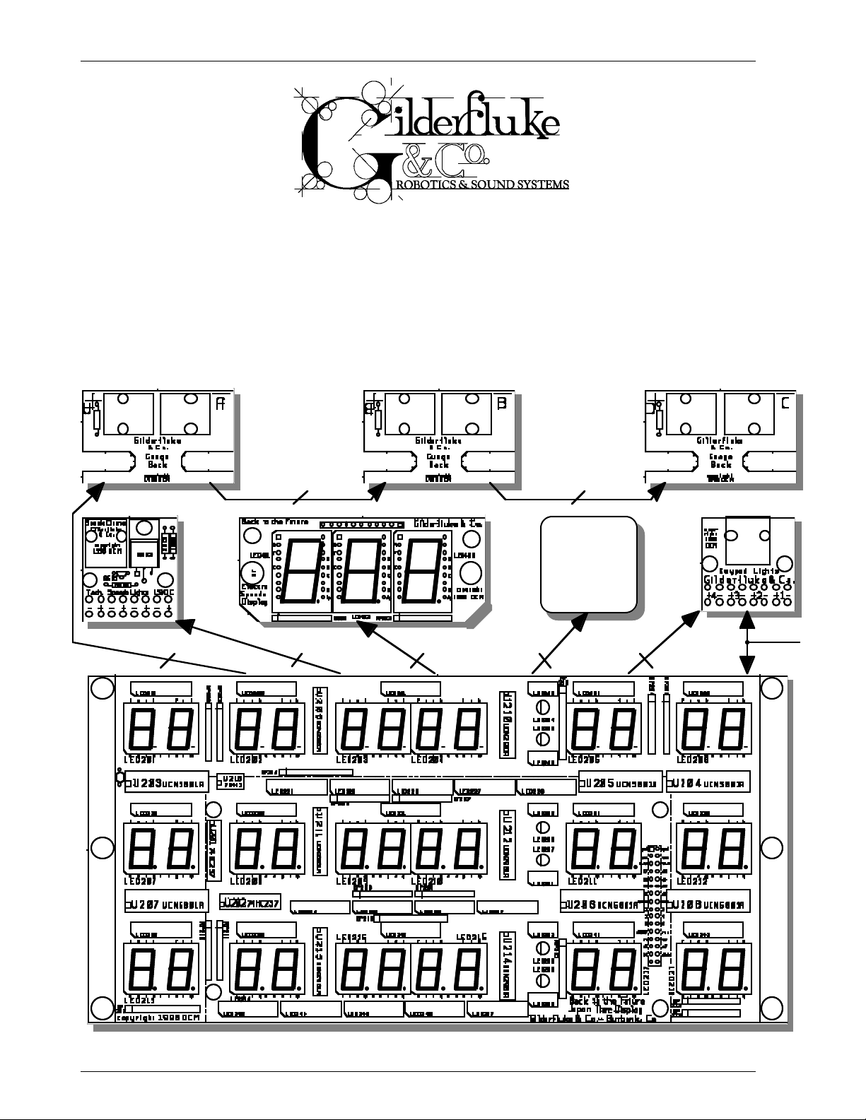
The mounting holes and printed circuit board outlines are identical to those used in
both California and Florida attractions to allow for easy retrofits. The Back to the Future
Japan dashboard consists of nine printed circuit boards:
1) Time display. Similar to the Hollywood and Florida installations, but also included on this print-
ed circuit board are the drivers and decoding logic which had been on a second circuit
board in the original attractions.
The original Back to the Future attractions used cheap low output seven segment displays
and LEDs which were scanned at a one of thirteen rate. This new version uses an optimum
one of six multiplexing and LEDs and much higher quality (Hewlet-Packard) displays. These are
rated for a light output of three to four times those that were used in the original attractions.
The net result of this is an output level which will is potentially six to eight times brighter than
was possible on the original attractions.
The display printed circuit board is currently configured for operating the displays and a
small number of LEDs from the regulated five volt supply. This will reduce heat dissipation to
less than 1/8 watt per resistor. The LED bars which are used for backlighting the silkscreened
overlay will be run from the unregulated fifteen volt supplied to the the Time Display. This is
because with four LEDs in series in each LED assembly, a five volt supply simply won’t allow for
enough of a forward voltage drop (2 volts x 4 = 8 volts). The ground side of the back lights is
switched through a 75451 to allow for dimming the back lights.
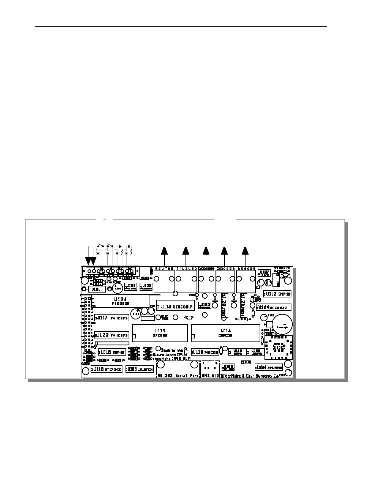
2) CPU: This is a 3.25” x 6.15” printed circuit board that attaches to the back of the time display.
It contains the DS87C520 microcontroller that runs the whole dashboard.
15 VDC
Start Show 1
Status 1
Start Show 2
Status 2
Four
Digitals
RJ-45
Serial Port
for setting
Digitals
Clock
Three
RJ-45
two
analogs/
Serial
RS-422
data
RJ-08
DMX-512 for
Programming
and testing
one
PWM
RJ-12
Three
analogs
RJ-12
The 32 MHz oscillator runs the microcontroller and baud clock for the DMX-512 input. The
1.8432 MHz oscillator provides the time base for the show playback (at 30 FPS), low speed serial port, and display multiplexing. All socketed ICs are held in place by pull ties.
Show memory is contained in a single thirty-two pin Eprom (27C040). The show data is
based on the program we created for Universal Studios, Hollywood. Several channels have
been added for the additional analog and digital channels used on the Back to the Future
2
Page 3
GILDERFLUKE & CO. • 205 SOUTH FLOWER STREET • BURBANK, CALIFORNIA91502 • 818/840-9484 • 800/776-5972 • FAX 818/840-9485
EAST COAST/FLORIDA OFFICE • 7041 GRAND NATIONAL DRIVE • SUITE 128d • ORLANDO , FL 32819 • 407/354-5954 • FAX407/354-5955
Japan dashboards. These are organized to retain compatibility with the California dashboards.
A Real Time Clock chip which has been laser trimmed for an accuracy of +/-10 PPM provides the clock data for the display. A battery retains RTC data when the car is powered
down. The firmware we have written will automatically adjust the clock to daylight savings time
if desired and the turn of the millennium after 1999. In the last three years, the California installation has only rarely needed to adjust the clocks in their retrofitted attraction.
The two eight position RJ-45 connectors provide the digital outputs needed to run the
lights on the keypad (four digital outputs) and LEDs in the Flux Capacitor (three digital
outputs). The output capacity of these eight outputs is 150 ma continuous, 500 ma peak.
These outputs are powered by the fifteen VDC that runs the dashboard.
The two six position RJ-12 connectors provide the 0-10 volt analog outputs needed to run
the meters on the speedometer (one PWM backlighting brightness and two analog outputs)
and Roentgen Gauges (three analog outputs). Five analog outputs are needed in total. A 2.5
volt, thermally stable reference is generated in the LM336-2.5. This is buffered and sent
through the DAC. The outputs of the DAC is amplified to 0-10 volt levels and sampled (and
held) in the SMP-18. The final outputs is then buffered by the two LM324s before sending the
voltages out to the gauges.
Four eight bit channels of animation data (three seven segment displays and one brightness command) are transmitted serially through the four position RJ-08 connector for use by
the E-Speedo display. This data is transmitted at 9600 baud using RS-422 signal levels.
A RS-232 port is provided for configuring the BttF2. Connection is via a standard DE-09
connector that extends from the bottom of the time display assembly.
The DMX-512 port is used to receive data from PC•MACs animation control systems for
programming the Back to the Future Japan CPU. It can also be used to receive animation
data from a Togglodyte test tool for field servicing the display and attached components.
Connection is via a standard miniature five position Mini-DIN connector that extends from the
bottom of the time display assembly.
Two optically isolated inputs are provided. A dipswitch can select between Japan and
California/Florida style starts. These inputs have resistors in series with them to be used with the
24 VDC inputs from the PLC.
Two optically isolated outputs are provided. These output animation data from the shows
that can be used as hearts or running status indicators. Currently, one is programmed to flash
at 2 Hz during the main show, and the other flashes at 2 Hz during the load/unload show.
The BttF2 design uses a 3 amp rated integrated switching regulator for powering both the
LED displays and the CPU printed circuit boards.
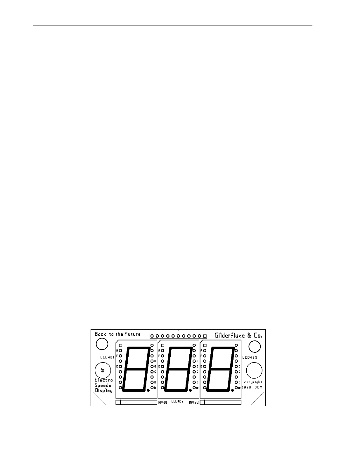
3) E-Speedo Display: This printed circuit board has three .8” tall yellow seven segment displays on
it. As with the time display printed circuit board, much higher quality displays are being used
for a potentially much brighter display than in either of the original attractions.
3
Page 4

GILDERFLUKE & CO. • 205 SOUTH FLOWER STREET • BURBANK, CALIFORNIA91502 • 818/840-9484 • 800/776-5972 • FAX 818/840-9485
EAST COAST/FLORIDA OFFICE • 7041 GRAND NATIONAL DRIVE • SUITE 128d • ORLANDO , FL 32819 • 407/354-5954 • FAX407/354-5955
4) E-Speedo CPU: This is a small printed circuit board that mounts directly behind the E-Speedo
display printed circuit board.
This printed circuit board receives the data for displaying via the RS-422 9600 baud serial
link from the main dashboard CPU printed circuit board. A Z8 microcontroller on this printed
circuit board decodes this data and multiplexes it (one of three) to the the displays. A five volt
integrated switching regulator on this printed circuit board provides both logic and display
power. All socketed ICs are held in place by pull ties.
5, 6, & 7) Roentgen Gauge Breakouts: Three small circuit printed circuit boards that attach di-
rectly to the back of the 0-10 volt Roentgen Gauge meter movements to ease attaching
them to the BttF2. Two of the gauges are Simpson 08890 2.5” gauges. The last gauge is a
Simpson 07660 4.5” gauge. Unlike the original installations, each gauge gets one of three
separate analog signals in the six position RJ-12 cable that daisy chains from the BttF2
through all three of these cards. Each card is labeled ‘A’, ‘B’, or ‘C’ to indicate which of the
analog signals will be used on that gauge. The polarity and identity of these cards is clearly
marked on each. Card ‘A’ is shown below.
8) Keypad Breakout: This small printed circuit board breaks out the eight position RJ-45 to discrete wire connections for each of the lights on the keypad assembly. There are no connections to the keypad itself, as it is purely decorative. On the original attractions, the four lights
were controlled on just two circuits (three of the four lights were hardwired together). The BttF2
provides individual programmed controls to each light. The polarity of each connection is
clearly marked on this card.
4
Page 5

GILDERFLUKE & CO. • 205 SOUTH FLOWER STREET • BURBANK, CALIFORNIA91502 • 818/840-9484 • 800/776-5972 • FAX 818/840-9485
EAST COAST/FLORIDA OFFICE • 7041 GRAND NATIONAL DRIVE • SUITE 128d • ORLANDO , FL 32819 • 407/354-5954 • FAX407/354-5955
9) Speedometer Cluster Breakout: This small printed circuit board breaks out the six position RJ-12
to discrete wires for connection to the speedometer and tachometer motors.
The speedometer and tachometer motors are 0-10 volt input Beede 9303430991. They
rotate approximately 270 degrees, based on the voltage input with no additional support circuitry.
The last signal to this breakout is used for dimming the speedometer cluster backlighting.
A 2N3906 bipolar transistor inverts this signal and feeds it to the input of a IRFZ44N ‘N’ channel FET power transistor for controlling the incandescent light bulbs used for the speedometer
cluster backlighting. With heat sinking, this FET is rated at over 40 amps continuous capacity.
Fifteen VDC power for the back lights must be run from the power supply to this card. The polarity of each connection is clearly marked on this card.
5
Page 6

GILDERFLUKE & CO. • 205 SOUTH FLOWER STREET • BURBANK, CALIFORNIA91502 • 818/840-9484 • 800/776-5972 • FAX 818/840-9485
EAST COAST/FLORIDA OFFICE • 7041 GRAND NATIONAL DRIVE • SUITE 128d • ORLANDO , FL 32819 • 407/354-5954 • FAX407/354-5955
- BTTF2 SERIAL PORTHOOKUP-
You can use just about any computer or terminal which has a serial port on it communicate with
the BttF2 through its RS-232 serial port.
If you are using a computer as a terminal you will need to run a modem or terminal emulation
program. These will send everything you type on the keyboard out the serial port on your computer
while printing on the screen anything that comes in from the BttF2 through the serial port. A modem
program will usually have the advantage over a terminal emulation program in that it will allow you to
save data to your computer's disk drives and restore it later. The BttF2 uses no screen control codes or
ESCape sequences, so it should work on any machine with a 80 column by 24 line display. Machines
with other display formats will work, but may not look so neat on the screen.
Typical modem programs you can use are Terminal.exe (which comes with Windows 3.1) and
Hyper Terminal.exe (which comes with Windows ‘95 and ‘98). If you can, find a copy of Terminal.exe,
as it is a better program than the later Hyper Terminal.
When configuring your modem program, you should set it for 9600 baud, 8 data bits, one stop
bit, and no parity. You should set your program not to insert an extra LineFeed (LF) character after
each Carriage Return (CR) it receives, or else the menus will print ‘double spaced’.
If you have hooked up the BttF2 to your computer and it still doesn’t seem to respond to the key-
board, the first thing to check is that you are attached to the right serial port. The easiest way to do
this is to disconnect the BttF2 and short between the Tx data out and Rx data in pins on the serial port
connector on the back of your computer. On all IBMs and compatibles this means sticking a paper
clip or similar tool between pins 2 and 3 on the ‘Com.’ connector. While still running the modem program, anything you type should appear on the screen while this paper clip is in place, while nothing
will appear when you remove it. If your computer passes this test, then you are using the right serial
port and the problem is most likely the baud rate setting or in your wiring to the BttF2. If you get characters on the screen even with the paper clip removed from the serial port, it means you probably
need to set the ‘echo’ mode to ‘none’ or ‘full duplex’. Then you should repeat this test.
The serial data signals from the BttF2 are brought out on a standard nine position PC-AT serial port
connection. A nine pin male to nine pin female serial cable with ‘straight through’ wiring should be
used to connect the BttF2 to your PC. The only pins that the BttF2 actually uses are the Txd, Rxd and
ground (pins #2, #3 and #5).
The BttF2 expects to see the serial data in the following format:
ONE START BIT
EIGHT DATA BITS
ONE BIT
6
Page 7

GILDERFLUKE & CO. • 205 SOUTH FLOWER STREET • BURBANK, CALIFORNIA91502 • 818/840-9484 • 800/776-5972 • FAX 818/840-9485
EAST COAST/FLORIDA OFFICE • 7041 GRAND NATIONAL DRIVE • SUITE 128d • ORLANDO , FL 32819 • 407/354-5954 • FAX407/354-5955
- BTTF2 COMMANDS-
The screen that the BttF2 will send to your computer looks like this:
- Gilderfluke & Co. - Back to the Future Japan - ver 1.01 - copyright 1998 DCM -
EPROM: _56 channels @ 30 FPS / first show is 07305 frames long
a) set time....
c) Start Inputs (Dipsw #1) - Japan
d) Automatic Daylight Savings Time (Dipsw #2) - no
e) numbering system (Dipsw #3) - Decimal
f) VT-52 Compatible terminal (Dipsw #4) - yes
g) play on every full hour (Dipsw #5) - no
h) play on every quarter hour (Dipsw #6) - yes
i) play every five minutes (Dipsw #7) - no
p) play main show now....
(12) 12:19:00pm Tuesday January 26, 1999 command-
•••••••••••••••••••••••••••••••••••••••••••••••••••••••••••••••••••••••••••••••••••••••••••••••••••••••••••••••••••••••••••••••••••••••••••••••••••••••••••••••
"a" Set Time:
This command will prompt you for the current date and time to be set on the Time/Date display. If you
would like the BttF2 to adjust automatically to daylight savings time, turn on Dipswitch #2.
•••••••••••••••••••••••••••••••••••••••••••••••••••••••••••••••••••••••••••••••••••••••••••••••••••••••••••••••••••••••••••••••••••••••••••••••••••••••••••••••
"c" Start Inputs (Dipsw #1):
When this dipswitch is OFF, the BttF2 will use the starts as specified in the Japanese Back to the Future
attraction (one input starts the main show, the other input starts the load/unload show). When this
switch is ON, the BttF2 will use the start signals as found in the California and Florida installations
(bizarre).
•••••••••••••••••••••••••••••••••••••••••••••••••••••••••••••••••••••••••••••••••••••••••••••••••••••••••••••••••••••••••••••••••••••••••••••••••••••••••••••••
"d" Automatic Daylight Savings Time (Dipsw #2):
When this dipswitch is ON, the BttF2 will use Daylight Savings time at the appropriate time of year.
7
Page 8

GILDERFLUKE & CO. • 205 SOUTH FLOWER STREET • BURBANK, CALIFORNIA91502 • 818/840-9484 • 800/776-5972 • FAX 818/840-9485
EAST COAST/FLORIDA OFFICE • 7041 GRAND NATIONAL DRIVE • SUITE 128d • ORLANDO , FL 32819 • 407/354-5954 • FAX407/354-5955
•••••••••••••••••••••••••••••••••••••••••••••••••••••••••••••••••••••••••••••••••••••••••••••••••••••••••••••••••••••••••••••••••••••••••••••••••••••••••••••••
"e" Numbering System (Dipsw #3):
When this dipswitch is OFF, the BttF2 will use decimal numbering for the show length display on this
screen. When this dipswitch is ON, the BttF2 will use Hexadecimal numbering for the show length display on this screen.
•••••••••••••••••••••••••••••••••••••••••••••••••••••••••••••••••••••••••••••••••••••••••••••••••••••••••••••••••••••••••••••••••••••••••••••••••••••••••••••••
"f" VT-52 Display (Dipsw #4):
When this dipswitch is ON, the BttF2 will use special screen codes to randomly position the cursor on
the screen. There is very little reason to ever turn this switch ON.
•••••••••••••••••••••••••••••••••••••••••••••••••••••••••••••••••••••••••••••••••••••••••••••••••••••••••••••••••••••••••••••••••••••••••••••••••••••••••••••••
"g" Play on every Full Hour (Dipsw #5):
"h" Play on every Quarter Hour (Dipsw #6):
"i" Play on every Five Minutes (Dipsw #7):
When any of these dipswitches are ON, the BttF2 will automatically play the main show every hour, fifteen minutes or five minutes. These can be used for cycle testing the BttF2 or to use the BttF2 as a
lovely office clock.
•••••••••••••••••••••••••••••••••••••••••••••••••••••••••••••••••••••••••••••••••••••••••••••••••••••••••••••••••••••••••••••••••••••••••••••••••••••••••••••••
"p" Play Main Show Now:
This command is used to start the main show playing from the serial port of the BttF2.
•••••••••••••••••••••••••••••••••••••••••••••••••••••••••••••••••••••••••••••••••••••••••••••••••••••••••••••••••••••••••••••••••••••••••••••••••••••••••••••••
<space bar> or <ESC>ape key Redraw Screen:
Pressing either the <space bar> or <ESC>ape key will tell the BttF2 to redraw the screen. Changes in
the dipswitches will not be reflected on the screen until it is redrawn.
•••••••••••••••••••••••••••••••••••••••••••••••••••••••••••••••••••••••••••••••••••••••••••••••••••••••••••••••••••••••••••••••••••••••••••••••••••••••••••••••
8
Page 9

GILDERFLUKE & CO. • 205 SOUTH FLOWER STREET • BURBANK, CALIFORNIA91502 • 818/840-9484 • 800/776-5972 • FAX 818/840-9485
EAST COAST/FLORIDA OFFICE • 7041 GRAND NATIONAL DRIVE • SUITE 128d • ORLANDO , FL 32819 • 407/354-5954 • FAX407/354-5955
- DECIMAL TO HEXADECIMAL TO ASCII TO PERCENTAGE -
The following chart shows decimal, HEXadecimal, ASCII and a few percentage equivalents to aid
you when you need to convert between numbering bases. Also shown are the ‘special’ characters
used by PC•MACs and Smart Brick Animation Control Systems. ASCII values that have their uppermost
bit set (bit 7) are shown in parenthesis:
decimal HEX ASCII % decimal HEX ASCII % decimal HEX ASCII % decimal HEX ASCII %
0 0 00 h null 0 6 4 40 h @ 2 5% 1 2 8 80 h (null)50% (don’t care) 19 2 C0h (@) 75%
1 01h soh/^A 6 5 41h A 129 81h (soh) 193 C1h (A)
2 02h stx/^B 6 6 42h B 13 0 82h (stx) 19 4 C2h (B)
3 03h etx/^C 6 7 43h C 131 83h (etx/) 1 9 5 C3h (C)
4 04h eot/^D 6 8 44h D 13 2 84h (eot) 196 C4h (D)
5 05h eng/^E 69 45h E 1 3 3 85h (eng) 197 C5h (E)
6 06h ack/^F 70 46h F 1 34 86h (ack) 198 C6h (F)
7 0 7h bell/^G 71 47h G 135 87h (bell) 1 9 9 C7h (G)
8 08h bs/^H 72 48h H 13 6 88h (bs) 2 0 0 C8h (H)
9 09h ht/^I 7 3 49h I 137 89h (ht) 20 1 C9h (I)
1 0 0Ah lf/^J 7 4 4Ah J 1 38 8Ah (lf) 20 2 CAh (J)
1 1 0Bh vt/^K 7 5 4Bh K 1 3 9 8Bh (vt) 203 CBh (K)
1 2 0Ch ff/^L 7 6 4Ch L 1 4 0 8Ch (ff) 20 4 CCh (L)
13 0Dh cr/^M 77 4Dh M 141 8Dh (cr) 205 CDh (M)
1 4 0Eh so/^N 78 4Eh N 14 2 8Eh (so) 2 0 6 CEh (N)
1 5 0Fh si/^O 79 4Fh O 14 3 8Fh (si) 2 07 CFh (O)
1 6 10h dle/^P 80 50h P 1 44 90h (dls) 2 0 8 B0h (P)
17 11h dc1/^Q 81 51h Q 1 4 5 91h (dc1) 209 B1h (Q)
18 12h dc2/^R 82 52h R 14 6 92h (dc2) 210 B2h (R)
19 13h dc3/^S 83 53h S 147 93h (dc3) 211 B3h (S)
20 14h dc4/^T 8 4 54h T 148 94h (dc4) 21 2 B4h (T)
2 1 15h nak/^U 8 5 55h U 149 95h (nak) 2 13 B5h (U)
2 2 16h syn/^V 86 56h V 1 50 96h (syn) 21 4 B6h (V)
23 17h etb/^W 87 57h W 1 5 1 97h (etb) 215 B7h (W)
24 18h can/^X 8 8 58h X 152 98h (can) 2 16 B8h (X)
2 5 19h em/^Y 8 9 59h Y 15 3 99h (em) 2 1 7 B9h (Y)
2 6 1Ah sub/^Z 90 5Ah Z 1 5 4 9Ah (sub) 2 18 BAh (Z)
27 1Bh ESC 9 1 5Bh [ 155 9Bh (ESC) 2 1 9 BBh ([)
28 1Ch FS 92 5Ch \ 156 9Ch (FS) 22 0 BCh (\)
2 9 1Dh GS 9 3 5Dh ] 15 7 9Dh (GS) 22 1 BDh (])
3 0 1Eh RS 94 5Eh ^ 1 5 8 9Eh (RS) 2 2 2 BEh (^)
3 1 1Fh VS 95 5Fh 15 9 9Fh (VS) 2 2 3 BFh ( )
32 20h SP 12.5% 96 60h ` 37.5% 160 A0h (SP) 62.5% 224 E0h (`) 87.5%
33 21h ! 97 61h a 16 1 A1h (!) 225 E1h (a)
34 22h “ 98 62h b 162 A2h (“) 226 E2h (b)
35 23h # 99 63h c 163 A3h (#) 22 7 E3h (c)
36 24h $ 100 64h d 164 A4h ($) 228 E4h (d)
37 25h % 101 65h e 165 A5h (%) 229 E5h (e)
38 26h & 102 66h f 166 A6h (&) 230 E6h (f)
39 27h ‘ 103 67h g 167 A7h (‘) 231 E7h (g)
40 28h ( 104 68h h 168 A8h (() 232 E8h (h)
41 29h ) 105 69h i 169 A9h ()) 233 E9h (i)
42 2Ah * 106 6Ah j 170 AAh (*) 234 EAh (j)
43 2Bh + 107 6Bh k 171 ABh (+) 235 EBh (k)
44 2Ch ‘ 108 6Ch l 172 ACh (‘) 236 ECh (l)
45 2Dh - 109 6Dh m 173 ADh (-) 237 EDh (m)
46 2Eh • 110 6Eh n 174 AEh (•) 238 EEh (n)
47 2Fh / 111 6Fh o 175 AFh (/) 239 EFh (o)
48 30h 0 112 70h p 176 B0h (0) 240 F0h (p)
49 31h 1 113 71h q 177 B1h (1) 241 F1h (q)
50 32h 2 114 72h r 178 B2h (2) 242 F2h (r)
51 33h 3 115 73h s 179 B3h (3) 243 F3h (s)
52 34h 4 116 74h t 180 B4h (4) 244 F4h (t)
53 35h 5 117 75h u 181 B5h (5) 245 F5h (u)
54 36h 6 118 76h v 182 B6h (6) 246 F6h (v)
55 37h 7 119 77h w 183 B7h (7) 247 F7h (w)
56 38h 8 120 78h x 184 B8h (8) 248 F8h (x)
57 39h 9 121 79h y 185 B9h (9) 249 F9h (y)
58 3Ah : 122 7Ah z 186 BAh (:) 250 FAh (z)
59 3Bh ; 123 7Bh 187 BBh (;) 251 FBh ( )
60 3Ch < 124 7Ch 188 BCh (<) 252 FCh ( )
61 3Dh = 125 7Dh | 189 BDh (=) 253 FDh (|)
62 3Eh > 126 7Eh ~ 190 BEh (>) 254 FEh (~)
63 3Fh ? 127 7Fh del 191 BFh (/) 255 FFh (del) 100%
9
 Loading...