

Page 1
GILDERFLUKE & CO.¥ 205 S. FLOWER ST. ¥ BURBANK, CA 91502 ¥ 818/840-9484 ¥ 800/776-5972 ¥ FAX 818/840-9485
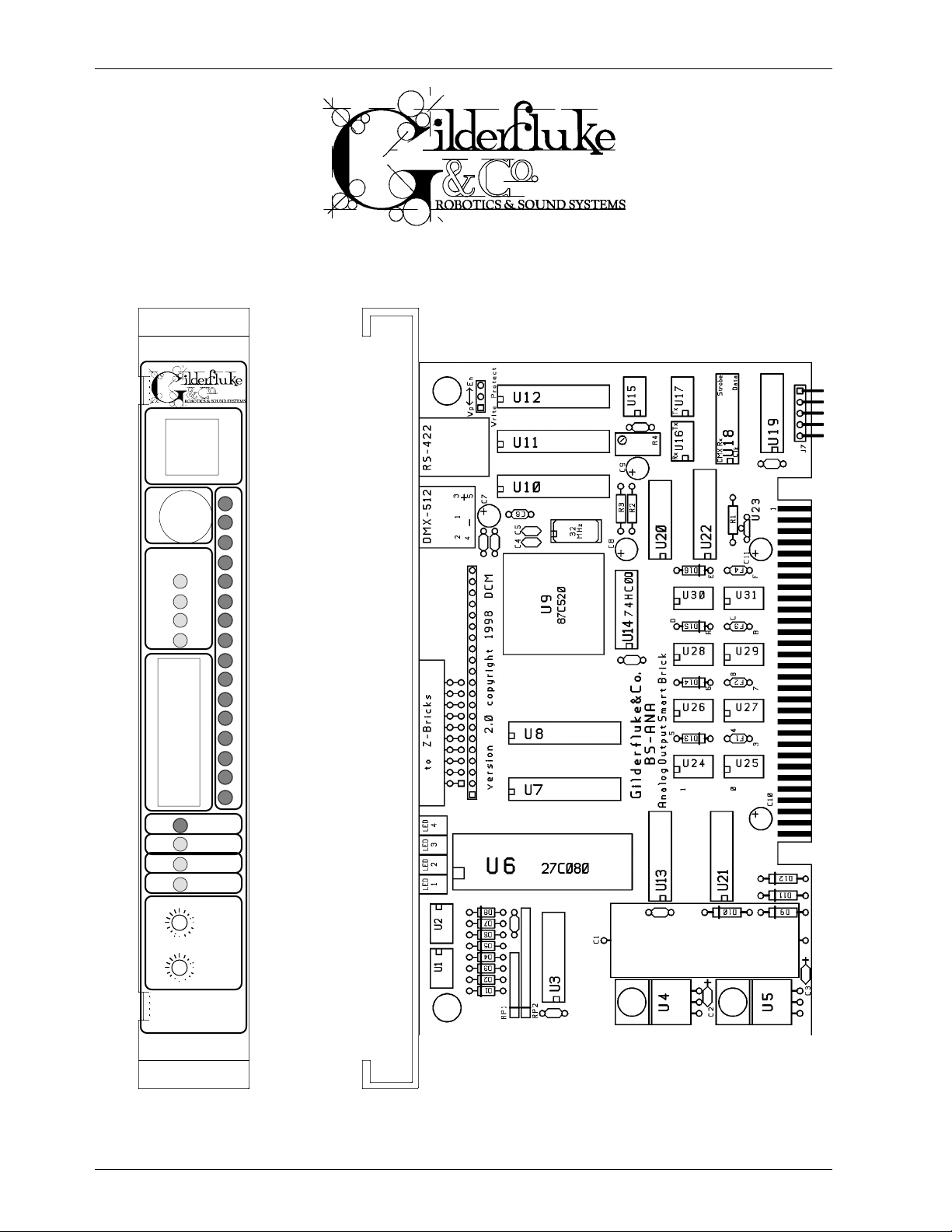
Analog Output Smart Brick
Printed July 19, 1999
RS-422 Serial Port
F
C-F
8-B
4-7
0-3
Z-Bricks
Board Error
DMX-512
Brick Heart
Heartbeat
E0
0080
2060
Address
0E
0008
0206
E
D
C
B
A
9
8
7
6
5
4
3
2
1
0
DMX-512
Output Fuses
C0
A0
40
0C
0A
04
Smart
Analog
i of iii
Page 2

GILDERFLUKE & CO.¥ 205 S. FLOWER ST. ¥ BURBANK, CA 91502 ¥ 818/840-9484 ¥ 800/776-5972 ¥ FAX 818/840-9485
This page left blank
ii of iii
Page 3

GILDERFLUKE & CO.¥ 205 S. FLOWER ST. ¥ BURBANK, CA 91502 ¥ 818/840-9484 ¥ 800/776-5972 ¥ FAX 818/840-9485
Overview .............................................................................................. 1
BS-ANA as a Remote Terminal Unit (RTU) ........................................................................... 1
BS-ANA as a Smart Brick ................................................................................................... 1
Front of the Analog Smart Brick ................................................................ 3
RS-422 Serial Port ............................................................................................................ 3
PC and Compatible Connections ................................................................................ 3
Apple Macintosh Connections ..................................................................................... 3
DMX-512 Data In/Out ....................................................................................................... 3
Output Fuse Indicators ..................................................................................................... 4
Output Level Indicators .................................................................................................... 4
Z-Brick .............................................................................................................................. 4
Board Error LED ................................................................................................................5
DMX-512 LED ....................................................................................................................5
Brick Heart ....................................................................................................................... 5
Heartbeat ......................................................................................................................... 5
Address ............................................................................................................................ 5
BackPlane Connections ........................................................................ 5
Animation Data Eproms ......................................................................... 9
Serial Port Commands ......................................................................... 11
To enter the configuration mode .................................................................................... 11
To display the status of this card .................................................................................... 11
To download the configuration of this card ................................................................... 11
To reload saved configuration ....................................................................................... 11
Analog Smart Brick Configuration .......................................................... 12
Use Front Panel Address ................................................................................................ 14
First Output Addressed At ............................................................................................... 14
DMX Rx Checksum ......................................................................................................... 14
Over Sampling enabled ................................................................................................. 14
Sequencer Enabled ........................................................................................................ 14
sequencer frame rate /2 ................................................................................................ 14
Numbering System ......................................................................................................... 14
VT-52 Compatible Display .............................................................................................. 15
twelve bit resolution ...................................................................................................... 15
Output to Test & Adjust ................................................................................................... 15
Test Output ..................................................................................................................... 15
Test One Output ........................................................................................................ 15
Test All Outputs .......................................................................................................... 15
auto Ease-In ...................................................................................................................15
Set Analog Endpoints ...................................................................................................... 16
Force Output to a Value ................................................................................................. 16
set Min/Max/forced using keypad .................................................................................. 16
PowerOn Defaults .......................................................................................................... 18
Download configuration ................................................................................................ 18
Reload Default Configuration ........................................................................................ 18
eXit ................................................................................................................................. 18
Upload configuration ..................................................................................................... 19
+ .................................................................................................................................... 19
Data Dump ..................................................................................................................... 19
Using Z-Bricks with a BS-ANA .................................................................. 20
Output Capacity ....................................................................................................... 22
Decimal to HEXadecimal to ASCII to Percentage ...................................... 24
iii of iii
Page 4

GILDERFLUKE & CO.¥ 205 S. FLOWER ST. ¥ BURBANK, CA 91502 ¥ 818/840-9484 ¥ 800/776-5972 ¥ FAX 818/840-9485
iv of iv
Page 5

GILDERFLUKE & CO.¥ 205 S. FLOWER ST. ¥ BURBANK, CA 91502 ¥ 818/840-9484 ¥ 800/776-5972 ¥ FAX 818/840-9485
Overview:
This is an output card which has sixteen 0-10 volt analog outputs, a single DMX-512 output and a port for attaching Z-Bricks. The analog outputs can be set to use either eight or
twelve bits of resolution. It is designed to be used as an output card for use in a PC¥MACs
system, or as a playback only Smart Brick in a Smart Brick installation. It can be used in two
different ways:
1) BS-ANA as a Remote Terminal Unit (RTU): In this mode the card receives up to
256 channels of DMX-512 data transmitted by a PC¥MACs Animation Control
System, or any other source of DMX-512 data, and uses this to update its outputs. The BS-ANA can be addressed to use any DMX-512 address from 0 to 255.
The DMX-512 input allows the BS-ANA to be used as a permanent output device
for a PC¥MACs or other Animation or Lighting Control System, or the DMX-512
input can be used temporarily until an Eprom is programmed so the card can
be used as a Smart Brick.
2) BS-ANA as a Smart Brick: This card acts just like any other Playback-Only Smart
Brick, playing animation data from an on-board Eprom. As a Smart Brick, it requires a Smart Brick Brain to run. The Smart Brick Brain tells all of the Smart bricks
attached to it (including the BS-ANA) where in the show it is. The BS-ANA then uses
this information to access the appropriate data in the Eprom and update its outputs. The animation sequence which is to be is used on the Analog Output Smart
Brick is usually generated on a PC¥MACs Animation Control System. While it is
being generated, the DMX-512 input mode is used so that you can see the animation data.
In either of the above modes, the first sixteen channels of data addressed are converted to individual 0-10 volt analog outputs. If twelve bit resolution has been selected for the
outputs, then the first 24 channels of data are converted to individual 0-10 volt analog values. If the Z-Brick and/or DMX-512 outputs are enabled, all 256 channels of DMX-512 or
Eprom data are also retransmitted through the Z-Brick and/or DMX-512 data outputs. The ZBrick output can be used for additional digital outputs through one or more Z-Bricks. The
DMX-512 output can be used to control light dimmers, automated spotlights, color changers, fog and wind machines, or any other pieces of equipment which will accept standard
DMX-512 inputs.
The BS-ANA can be mounted in one 1Ó wide slot in any of our Brick Card cages. The BSANA can be used in conjunction with any selection of Smart Bricks, Smart Brick Brains,
Electronic FeedBack (EFB) Smart Bricks and Z-Bricks in the same card cage. Card cages
with one, two or sixteen slots are available. The card cages provide all of the connections
for power supply, control signals and outputs that any Brick card will need. Several different
styles of output connectors are available on the one and two slot card cages. The sixteen
slot card cage mounts in seven inches of standard 19Ó rack space (4-1/2 Ò of space behind the panel). In some applications you may need to mount a single Smart Brick. This
can be done by mounting the Brick on standoffs, and connecting to the card's edge connector with a mating connector. We usually recommend a sixty position insulation displacement connector for this type of installation.
1 of 24
Page 6

GILDERFLUKE & CO.¥ 205 S. FLOWER ST. ¥ BURBANK, CA 91502 ¥ 818/840-9484 ¥ 800/776-5972 ¥ FAX 818/840-9485
Power requirements for each BS-ANA are 18 to 24 VDC. The actual current requirements
are determined by the loads attached to the unit (up to 20 ma. per output). The Smart
Analog Brick itself draws approximately 200 ma..
2 of 24
Page 7

GILDERFLUKE & CO.¥ 205 S. FLOWER ST. ¥ BURBANK, CA 91502 ¥ 818/840-9484 ¥ 800/776-5972 ¥ FAX 818/840-9485
On the Front of the Analog Smart Brick:
A) RS-422 Serial Port: This is used to configure the BS-ANA. It is compatible with all of the RS-422
Serial Ports used on Gilderfluke & Company products.
As a convenience, the four active lines on this connector are bussed to the backplane of
the card cage. This allows you to communicate to a whole card cage full of BS-ANAs, Smart
Brick Brains, Electronic FeedBack (EFB) Smart Bricks and other cards through the connector on
any single card. They just need to be set to different addresses. If desired, permanent connections can be made on the back of a card cage.
The serial data signals from the BS-ANA are brought out on a six position RJ-11 (modular
telephone style connector). Facing the end of the cable with the release latch upwards, its
pin out is as follows:
COLOR SIGNAL NAME:
LEFT #1 white Signal Ground
#2 black - Serial data out from card
#3 red + Serial data out from card
#4 green - Serial data in to card
#5 yellow + Serial data in to card
RIGHT #6 blue Signal Ground
PC and Compatible Connections: If you are only talking to a single BS-ANA and your wire
length is short, you may be able to simply cross wire the RS-232 serial port on your PC to talk
to the BS-ANA. This does not work on all PCs, as some donÕt swing their RS-232 outputs as far as
they should. If it does not work with your PC, you may need to get a RS-232 to RS-422 converter to talk to the BS-ANA. To cross wire the RS-422 / RS-485 signals from the BS-ANA to the
RS-232 serial port of an IBM compatible, cross connect the signals as follows:
DB-25 DE-9 Signal Signal from/to BS-ANA
2 3 DATA OUT - Serial data into card (#4 green)
3 2 DATA IN - Serial data out from card (#2 black)
7 5 GROUND Signal Ground (#1 white or #6 blue)
Apple Macintosh Connections: Apple Macintosh computers have true RS-422 serial ports
built in. To connect to the BS-ANA, the pin out is as follows (view is of male connector facing
the end of the cable):
to + serial data in to card (#5 yellow)
to - serial data in to card (#4 green)
signal ground (#1 blue or #6 white)
The BS-ANA expects to see the serial data in the following format:
678
345
12
from + serial data out from card (#3 red)
from - serial data out from card (#2 black)
ONE START BIT
EIGHT DATA BITS
ONE STOP BIT
Unlike many of the products manufactured by Gilderfluke & Company, the BS-ANA responds only to the command to enter the configuration mode, download/upload configuration and status enquiries. It will ignore all other commands, which allows it to share the same
RS-422 serial line with additional BS-ANAs, Digital Audio Repeaters, Smart Brick Brains and other
serially controlled devices. The only requirement is that each unit be addressed to a different
location.
B) DMX-512 Data In/Out: Five pin MiniDIN connector. The BS-ANA will stop listening to the Smart
Brick network whenever there is a DMX-512 signal present on this input. If JP-1 is in the 'DMX'
position, then the two received data lines on this connector will be attached to pins 11 and
3 of 24
Page 8
GILDERFLUKE & CO.¥ 205 S. FLOWER ST. ¥ BURBANK, CA 91502 ¥ 818/840-9484 ¥ 800/776-5972 ¥ FAX 818/840-9485
12 on the backplane. This allows the DMX-512 signals to be bussed between cards within a
card cage. The default position for JP-1 is ÔneitherÕ.
The DMX-512 standard was developed by the United States Institute for Theatrical
Technology (USITT) for a high speed (250 KBaud) asynchronous serial data link. Although it was
originally designed for controlling light dimmers, it is now supported by hundreds of suppliers
throughout the world for controlling all kinds of theatrical equipment.
Even though the DMX-512 standard calls for 512 channels of data, the DMX transmission
from PC¥MACs is limited to 256 eight bit wide channels. You can address your DMX-512 compatible output devices to respond to any address between 00 and 255. Addresses above the
256th are used in PC¥MACs for transmitting a checksum. The BS-ANA can use this to verify that
the data received from PC¥MACs has no transmission errors in it. If you address a light dimmer
or other DMX-512 device to addresses 256 or 257, you will see this verification data displayed
as a flickering pattern. Note that at frame rates higher than forty FPS, not all 256 channels can
be transmitted through the DMX-512 output.
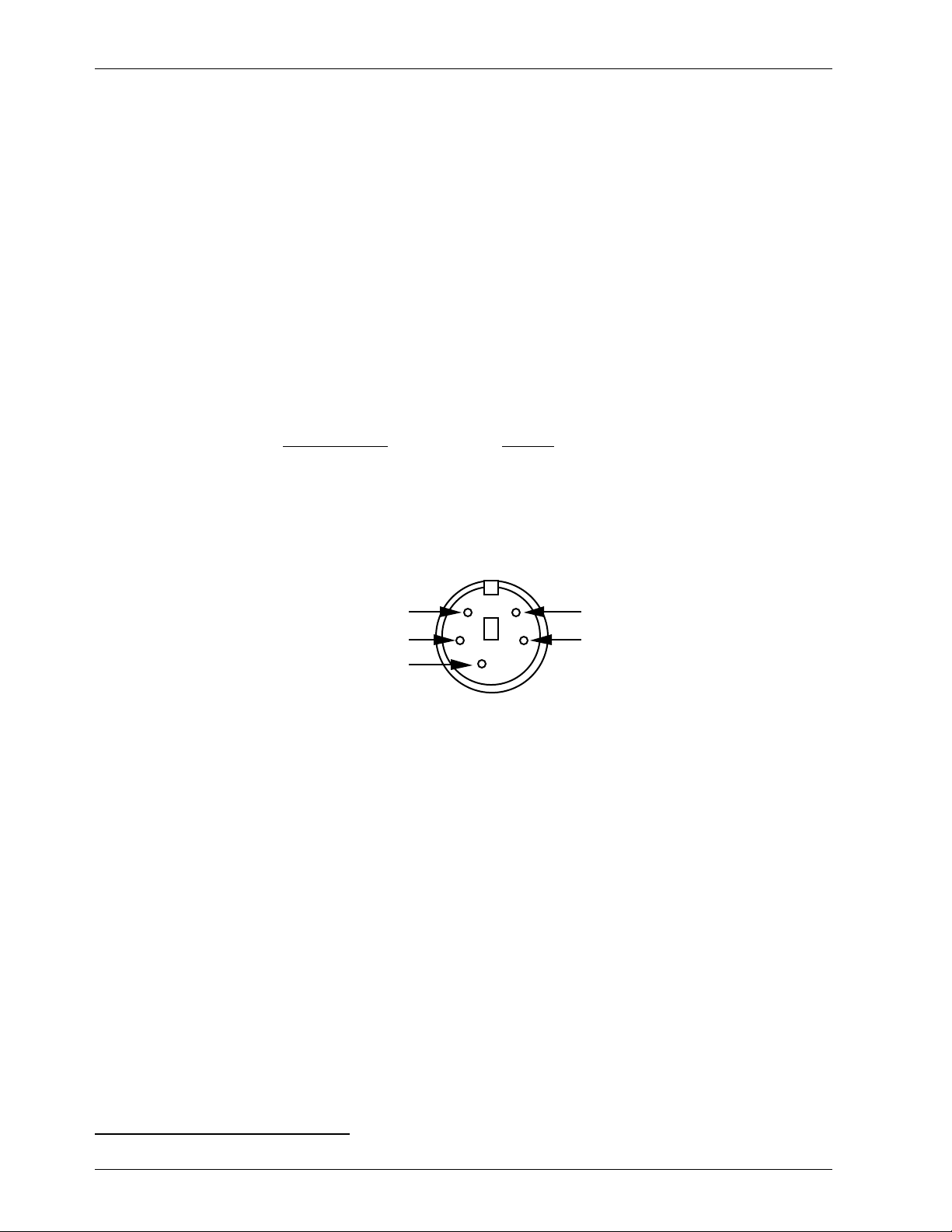
The DMX-512 standard calls out a 5 pin XLR connector for all cabling. Unfortunately these
connectors won't fit on a 1Ó wide card. For this reason we chose a 5 pin MiniDIN connector for
this signal. the pinout is as follows:
MiniDIN pin # SIGNAL
1
1 Signal Common (shield)
2 Dimmer Drive compliment (Rx Data -)
3 Dimmer Drive True (Rx Data +)
4 Data In True (Tx Data +)
5 Data In compliment (Tx Data -)
Facing the end of the male end of a cable, the pins are located as shown:
Data In True (Tx Data +)
Dimmer Drive Compliment (Rx Data -)
signal ground
4
23
5
1
Data In Compliment (Tx Data -)
Dimmer Drive True (Rx Data +)
Data from a PC¥MACs should be fed into pins #2 (-RxD) and #3 (+RxD). The shield should
be connected to pin #1.
Only 256 channels of data are transmitted from the BS-ANA. Since the 256th and 257th
bytes are not transmitted, the checksum is not sent. The transmitted data will also pause when
the BS-ANA is busy as it redraws the screen in configuration mode. For this reason it should
only be used to control lighting and other equipment that doesn't mind an occasional pause
or data error.
C) Output Fuse Indicators: These four LEDs are lit unless one of the four PTC fuses has been
tripped by an overload on the J6/A output cable.
D) Output Level Indicators: These sixteen red LEDs show the current output level on all of the 0-
10 volt outputs. You will see these LEDs fade in and out as the signals on the outputs change.
E) Z-Brick: This twenty pin IDS connector is used to connect to one or more Z-Bricks. When en-
abled, the BS-ANA puts out data from the DMX-512 input or onboard Eprom to this connector.
The format of the data is as follows:
1
Don't blame us for these names. These are directly from the USITT.
4 of 24
Page 9

GILDERFLUKE & CO.¥ 205 S. FLOWER ST. ¥ BURBANK, CA 91502 ¥ 818/840-9484 ¥ 800/776-5972 ¥ FAX 818/840-9485
IDS pin # SIGNAL
1 Data bit 0
2 Data bit 1
3 Data bit 2
4 Data bit 3
5 Data bit 4
6 Data bit 5
7 Data bit 6
8 Data bit 7
9 Address bit 0
10 Address bit 1
11 Address bit 2
12 Address bit 3
13 Address bit 4
14 Address bit 5
15 Address bit 6
16 Address bit 7
17 ground
18 ground
19 Strobe/
20 Reset/
When the address and data lines are valid, the rising edge of the Strobe line will latch the
data into the addressed outputs.
F) Board Error LED: This LED will flash when:
1) Smart Analog Card just booted
2) An error is found in the DMX-512 data checksum
3) An error is found in the Smart Brick Network checksum
G) DMX-512 LED: This LED will be lit when the BS-ANA is receiving DMX-512 data.
H) Brick Heart: The heartbeat from the Smart Brick Brain is transmitted throughout the system
over the Smart Brick Network. The presence of a healthy heartbeat means that the data on
the Smart Brick Network is getting through cleanly. If it ever stutters or flashes erratically (or not
at all), then there is a problem with the Smart Brick Brain, the Smart Brick Network, or the BSANA. As the DMX-512 takes precedence over the Smart Brick Network, this LED will go dark
whenever a DMX-512 signal is present.
I) Heartbeat: This LED Flashes continuously while the CPU is running. If it ever stops for more than
a fraction of a second, the 'Deadman' circuit in the BS-ANA will automatically reset the CPU.
While performing an Ease-In, the heart rate will double.
J) Address: Two HEXadecimal switches that are used to set the base address for the card. This
address is always used to access the BS-ANA through the serial port. It is also normally the first
DMX-512 address used (data at this DMX-512 address will be output through output #0). The
DMX-512 address can also be set through the configuration screen. This will override the DMX512 address set by these switches.
5 of 24
Page 10

GILDERFLUKE & CO.¥ 205 S. FLOWER ST. ¥ BURBANK, CA 91502 ¥ 818/840-9484 ¥ 800/776-5972 ¥ FAX 818/840-9485
BackPlane Connections:
The BackPlane connection is through a sixty position double sided edge connector (thirty connections
on each side on .1Ó centers). This normally is plugged into a card cage, but can also be used with an IDS
or other discrete edge connector. We recommend an Insulation Displacement (IDE) connector for the latter.
The first ten positions are used for the Smart Brick network and RS-422 Serial Port. They are normally
bussed between all of the cards in the card cage (although they can be separated by cutting the lines if
desired).
The next forty positions are used to connect the J6/A signals to the output cabling.
The last ten positions are used to provide power to the BS-ANA. These wires are ganged to provide a
higher current carrying capacity. The pinout of this connector is as follows:
output wire # Edge pin # color wire function
Smart Brick net #2 1 black Smart Brick Network Data/ into BS-ANA
Smart Brick net #1 2 white Smart Brick Network Data into BS-ANA
Smart Brick net #3 3 red Smart Brick Network Clock into BS-ANA
Serial Port #3 4 red TxD + out from BS-ANA
Smart Brick net #4 5 green Smart Brick Network Clock/ into BS-ANA
Serial Port #2 6 black TxD - out from BS-ANA
Smart Brick net #5 7 yellow Smart Brick Network Strobe into BS-ANA
Serial Port #5 8 yellow Rx + into BS-ANA
Smart Brick net #6 9 blue Smart Brick Network Strobe into BS-ANA
Serial Port #4 10 green Rx -into BS-ANA
J6/A #1 11 brown circuit ground
J6/A #2 12 red + unregulated power output (protected to 1 amp)
J6/A #3 13 orange Output 15 (0Fh) Positive Analog Output
J6/A #4 14 yellow Output 15 (0Fh) Negative Reference
J6/A #5 15 green Output 14 (0Eh) Positive Analog Output
J6/A #6 16 blue Output 14 (0Eh) Negative Reference
J6/A #7 17 violet Output 13 (0Dh) Positive Analog Output
J6/A #8 18 gray Output 13 (0Dh) Negative Reference
J6/A #9 19 white Output 12 (0Ch) Positive Analog Output
J6/A #10 20 black Output 12 (0Ch) Negative Reference
J6/A #11 21 brown circuit ground
J6/A #12 22 red + unregulated power output (protected to 1 amp)
J6/A #13 23 orange Output 11 (0Bh) Positive Analog Output
J6/A #14 24 yellow Output 11 (0Bh) Negative Reference
J6/A #15 25 green Output 10 (0Ah) Positive Analog Output
J6/A #16 26 blue Output 10 (0Ah) Negative Reference
J6/A #17 27 violet Output 9 (09h) Positive Analog Output
J6/A #18 28 gray Output 9 (09h) Negative Reference
J6/A #19 29 white Output 8 (08h) Positive Analog Output
J6/A #20 30 black Output 8 (08h) Negative Reference
J6/A #21 31 brown circuit ground
J6/A #22 32 red + unregulated power output (protected to 1 amp)
J6/A #23 33 orange Output 7 (07h) Positive Analog Output
J6/A #24 34 yellow Output 7 (07h) Negative Reference
J6/A #25 35 green Output 6 (06h) Positive Analog Output
J6/A #26 36 blue Output 6 (06h) Negative Reference
J6/A #27 37 violet Output 5 (05h) Positive Analog Output
J6/A #28 38 gray Output 5 (05h) Negative Reference
J6/A #29 39 white Output 4 (04h) Positive Analog Output
J6/A #30 40 black Output 4 (04h) Negative Reference
6 of 24
Page 11

GILDERFLUKE & CO.¥ 205 S. FLOWER ST. ¥ BURBANK, CA 91502 ¥ 818/840-9484 ¥ 800/776-5972 ¥ FAX 818/840-9485
J6/A #31 41 brown circuit ground
J6/A #32 42 red + unregulated power output (protected to 1 amp)
J6/A #33 43 orange Output 3 (03h) Positive Analog Output
J6/A #34 44 yellow Output 3 (03h) Negative Reference
J6/A #35 45 green Output 2 (02h) Positive Analog Output
J6/A #36 46 blue Output 2 (02h) Negative Reference
J6/A #37 47 violet Output 1 (01h) Positive Analog Output
J6/A #38 48 gray Output 1 (01h) Negative Reference
J6/A #39 49 white Output 0 (00h) Positive Analog Output
J6/A #40 50 black Output 0 (00h) Negative Reference
n/a 51 black power supply ground
n/a 52 black power supply ground
n/a 53 black power supply ground
n/a 54 black power supply ground
n/a 55 black power supply ground
n/a 56 red + power supply input
n/a 57 red + power supply input
n/a 58 red + power supply input
n/a 59 red + power supply input
n/a 60 red + power supply input
In all the animation systems made by Gilderfluke & Company, all Analog input and output
cabling is through what we call 'J6/A' standard output cables. These are forty wire cables
which are made up of four identical four channel wide cables. A J6/A cable is often split up
into four individual cables called a 1/4 J6/A. Each 1/4 J6/A also includes a common power
supply and ground wire which allow it to provide power for analog output accessories like
Electronic FeedBack (EFB) controllers and Sixteen Channel Servo Controllers (both of these
cards require a power supply of 18 volts be used for the BS-ANA).
To simplify wiring to any MACs Animation Control System, the connectors used on the J6/A
cables are what are called 'insulation displacement connectors'. These simply snap on to an
entire cable, automatically 'displacing' the wire insulation and making contact with the wires
within. This means that an entire forty wire cable can be terminated in seconds. All connectors
are polarized, to keep them from being plugged in backwards.
Analog loads are connected between each of the Positive outputs and its associated
Negative reference. The output capacity of each output is 20 ma. The output voltage range
can be adjusted from the BS-ANA to anywhere between 0 and 10 volts. Current amplifiers are
available if additional current capacity is required for your application.
The negative reference is at a voltage of approximately 1.6 volts above the circuit ground.
The negative references are all connected on the BS-ANA, but there must be no direct
connections made between any of the negative references and the circuit
grounds anywhere in the animation system.
The '+ unregulated power output' for each 1/4 J6/A is protected by a solid state circuit
breaker (PTC Fuse) rated for 1 amp. You should treat each 1/4 J6/A as an individual, and not
cross the outputs or power output lines from one 1/4 J6/A to the lines from another. Doing this
won't cause any damage, but can reduce the protection for the outputs that the circuit
breakers normally provide. The 'Output Fuse' LEDs on the front of the BS-ANA show the condition of each of the PTC fuses. Each of these is a LED and resistor between the ground (pin #1
brown) wire and power output (pin #2 red) wire. Each of these will be lit if the corresponding
circuit breaker is OK. The resistor is 4.7 Kohms.
R4 is the one adjustment on the BS-ANA. It sets the gain for the Digital to Analog (D/A) converters on the board. To set it, pick any output and set the minimum and maximum scaling to
their minimums and maximums through the configuration screen. When you send a full scale
7 of 24
Page 12

GILDERFLUKE & CO.¥ 205 S. FLOWER ST. ¥ BURBANK, CA 91502 ¥ 818/840-9484 ¥ 800/776-5972 ¥ FAX 818/840-9485
output command to this output, you should then be able to adjust it for 10.00 volts using R4.
The adjustments for the endpoints on each of the sixteen outputs are individually set through
the setup screen.
8 of 24
Page 13

GILDERFLUKE & CO.¥ 205 S. FLOWER ST. ¥ BURBANK, CA 91502 ¥ 818/840-9484 ¥ 800/776-5972 ¥ FAX 818/840-9485
Animation Data Eproms:
The Eproms used for all all of the 'Brick' products manufactured by Gilderfluke & Company have traditionally each contained one channel (eight bits) worth of data. The Eproms used on the BS-ANA, EFB Smart
Brick and RTU/FSK Units for storing animation data each carry a number of channel's worth of data. The first
four bytes also contain the frame rate, number of channels and the length of the first show in the Eprom.
These are generated on a PC¥MACs system by:
1) Selecting the 'Save as Eprom...' command from the 'File' pulldown.
2) Check on the 'Multi Channel' checkbox
3) Set the 'start' and 'end' boxes to set the number channels you want to go into this multiple
Eprom file. A BS-ANA with all sixteen channels set to eight bit resolution, this will be sixteen
channels. A BS-ANA with all sixteen channels set to twelve bit resolution, this will be twenty-four
channels. If you are saving a twelve bit resolution Eprom, you must set the ÔstartÕ address (and
the BS-ANA address) to a multiple of three (or zero). Be sure to allow for enough extra channels
for any Z-Bricks that might be attached to the BS-ANA.
4) Use the ÔAddÕ button to select any additional show you would like to be saved into this Eprom
file set.
5) Use the ÔPromoteÕ and ÔDemoteÕ buttons to move selected show(s) into the order you would like
to save them in the Eprom.
6) Normally you will want to select the ÔCalculate Brick Start FramesÕ checkbox to allow PC¥MACs
to automatically calculate the offset into the Eproms needed for the shows you are saving. If
you would like to preserve the ÔStart frameÕ values in the show files, also check the ÔSave Brick
StartsÕ checkbox.
7) If you are not using the PC¥MACs calculated ÔBrick StartsÕ, you will have had to set these individually for each show under its File/Show Information dialog. If they are set improperly,
PC¥MACs will tell you if any of the shows are overlapping during the build. When using ÔBrick
StartsÕ that you have entered, PC¥MACs can pad the space between the shows with the default values for the movements if you have checked the ÔPad With Default ValuesÕ checkbox.
8) Press the ÔBuildÕ button to begin the saving process. A standard file save dialog will open.
Name the file as desired. (it defaults to the name of the first show in the list). PC¥MACs will
warn you if a file already exists with this name. Hit OK to save the data to a file.
Once the shows have been saved to the multiple show file, you can burn them into an Eprom using
any Eprom programmer that supports 27C010 through 27C080 Eproms.
If you press the ÔReportÕ button, PC¥MACs will display the information about the Eprom set you just
saved. This information is also saved in a text file with the same name as the Eproms, but with the extension of Ô.setÕ. You can open this file with any text editor like Notepad or Wordpad. The numbers shown for
ÔBrick startÕ and ÔBrick endÕ are what you need to enter into the Smart Brick Brain to set the start and end of
each show. The ÔEprom startÕ and ÔEprom endÕ are the actual locations of the shows in the Eprom set. The
number shown for the ÔEprom EndÕ for the last show in this file set is the last byte which will be saved into
the Eprom. If your Eprom is smaller than this number, you will need to use more than a single Eprom and a
memory expansion board for the BS-ANA. The capacities of all of the large Eproms are as follows:
Eprom type Total number of bytes
27C010 131,072
27C020 262,144
27C040 524,288
27C080 1,048,576
If additional capacity is needed, then a memory expansion board can increase the capacity of the BSANA to eight 27C080Õs (8,388,608 byte capacity).
Note that at least one show must be loaded starting at a 'Brick Start' of 0, even if it is only a frame or
two long. PC¥MACs will use this first show to set the frame rate and number of channels stored in the multiple channel Eprom. The BS-ANAs need this information to index into the Eprom.
9 of 24
Page 14

GILDERFLUKE & CO.¥ 205 S. FLOWER ST. ¥ BURBANK, CA 91502 ¥ 818/840-9484 ¥ 800/776-5972 ¥ FAX 818/840-9485
The Eprom file that PC¥MACs generates will have the extension of filename.Mnn. The 'M' in the extension flags it as a 'multiple channel' Eprom file. The 'nn' is the HEXadecimal address of the first channel in
the Eprom set. Once saved, this file can be burnt into any Eprom from 1 Mbit (27C010) to 8 Mbits
(27C080). The BS-ANA supports all four standard thirty-two pin Eproms.
The address of the data sent out from an Eprom may be different from what you saw when programming through the DMX-512 input. This is a question of the address selected for the BS-ANA and whether it
is addressed via the front panel switches or the software. Data sent out from the Eprom will be sent out
starting at DMX-512 and Z-Brick outputs 00h. The BS-ANA DMX-512 address should be addressed at 00h
(either using the front panel dipswitch or software address setting) to make sure the addresses are the
same when running from DMX or the on-board Eprom.
10 of 24
Page 15

GILDERFLUKE & CO.¥ 205 S. FLOWER ST. ¥ BURBANK, CA 91502 ¥ 818/840-9484 ¥ 800/776-5972 ¥ FAX 818/840-9485
Serial Port Commands:
The following commands are used to communicate with BS-ANAs and just about any other piece of
equipment manufactured by Gilderfluke & Company. Just by attaching the serial port of your PC, PLC or
terminal to the serial port of the Smart Brick, you can access these commands.
To enter the configuration mode: Type the following. The (address) is replaced by the HEX value
set when the BS-ANA is configured.
m5AA5(address)
If any other card is in configuration mode (or even if it just thinks another card is in configuration), the BS-ANA won't be able to enter configuration mode. To exit any other card from
configuration type 'XN'. You can then try entering configuration again.
To display the status of this card: Send the card an Ôi(address)Õ. The (address) is replaced by the
HEX value set when the BS-ANA is configured.
To download the configuration of this card: Prepare your computer to receive and save a
stream of ascii characters. Send the card a Ôr(address)Õ. The (address) is replaced by the HEX
value set when the BS-ANA is configured. The card will respond with a stream of 1043 bytes of
ascii data. Any number of additional cards (either more BS-ANAs or any other card made by
Gilderfluke & Company) can also have their configuration downloaded into the same file by
giving them the same command with the appropriate addresses appended on. When you are
done downloading configurations, you can tell your computer to stop saving received ascii to
a file.
To reload saved configuration: All you need to do is send this file back to the cards through your
computerÕs serial port. All cards that were addressed will hear their address in the data stream
and load in the configuration data.
11 of 24
Page 16

GILDERFLUKE & CO.¥ 205 S. FLOWER ST. ¥ BURBANK, CA 91502 ¥ 818/840-9484 ¥ 800/776-5972 ¥ FAX 818/840-9485
Analog Smart Brick Configuration:
To communicate with the BS-ANA through the serial port, you can use just about any computer or terminal which has a serial port on it. Some newer computer designs, like the Apple Macintosh, come with
serial ports which are directly compatible with the RS-422 / RS-485 signal levels the BS-ANA wants to see.
These signal levels are close enough to be used with the RS-232 signal levels found on most older computers (like most IBMs and compatibles) with only a simple adapter cable, so long as the wire isn't too long.
To gain the full advantage of the RS-422 / RS-485 signal levels you will need to use a signal level adapter
like our 232conv-09.
If you are using a computer as a terminal you will need to run a modem or terminal emulation program. These will send everything you type on the keyboard out the serial port on your computer while
printing on the screen anything which comes in from the BS-ANA through the serial port. Every copy of
Windows comes with HyperTerm or Terminal.EXE, which are just such programs. Z-Term is available as
shareware (free) from most Bulletin Board Systems and users groups for Macintosh computers. A modem
program will usually have the advantage over a terminal emulation program in that it will allow you to save
data to your computer's disk drives and then send it back to the BS-ANA at a later date. The BS-ANA uses
no screen control codes or ESCape sequences (unless VT-52 compatible mode has been enabled), so it
should work on any machine with an eighty column by twenty-four line display. Machines with other display formats will work, but may not look so neat on the screen.
When configuring your modem program, you should set it for 9600 baud, 8 data bits, one stop bit and
no parity. You should set handshaking to ÔXon/XoffÕ. Hardware handshaking must be turned off. If your terminal emulation program supports VT-52 terminal emulation (they all do!), you should enable it. This will
allow faster screen redraws if 'VT-52 compatible' mode is enabled on the BS-ANA. You should set your program NOT to insert an extra LineFeed (LF) character after each Carriage Return (CR) it receives. You
should also tell it NOT to scroll automatically after the eightieth column is filled. If either of these are on,
the screen will be displayed 'double spaced'. This won't cause any problem, but will make it hard to see
the whole screen at one time.
If you have hooked up the BS-ANA to your computer and it still doesn't seem to respond to the keyboard, the first thing to check is that you are attached to the right serial port. The easiest way to do this is
to disconnect the BS-ANA and short between the Tx data out and Rx data in pins on the serial port connector on the back of your computer. On all IBMs and compatibles this means sticking a piece of wire,
paper clip, or similar tool between pins 2 and 3 on the 'Com.' connector. While still running the modem
program, anything you type should be shown on the screen while this paper clip is in place, while nothing
will appear when you remove it. If your computer passes this test, then you are using the right serial port
and the problem is most likely the baud rate setting or in your wiring to the BS-ANA. If you get characters
on the screen even with the paper clip removed from the serial port, it means you probably need to set
the 'echo' mode to 'none' or 'full duplex' and try this test again.
To enter the configuration mode you need to type the following. The (address) is replaced by the HEX
value set on the ADDRESS switches on the front of the BS-ANA:
m5AA5(address)
If any other card is in configuration mode (or even if it just thinks another card is in configuration), the
BS-ANA won't be able to enter configuration mode. To exit any other card from configuration type 'XN'.
You can then try entering configuration again.
To redraw the screen at any time, just press the <ESC>ape key or <SPACE> bar. The BS-ANA will display the following screen:
12 of 24
Page 17

GILDERFLUKE & CO.¥ 205 S. FLOWER ST. ¥ BURBANK, CA 91502 ¥ 818/840-9484 ¥ 800/776-5972 ¥ FAX 818/840-9485
Configuration Screen:
For eight bit resolution outputs, the menu will appear as follows. Percentage values have been selected for the numbers. At the top of the screen the size of the Animation Data Eprom installed (if any) is
shown. If the Animation Data Eprom isn't found, then 'not found' will appear in this space.
-Gilderfluke & Company - Analog Smart Brick - version 2.02 - copyright 1998 DCM-
EPROM: _16 channels @ 30 FPS / first show is 06450 frames long
a) use front panel address- yes MSB E minimum maximum forced PowerOn
b) first output addressed at __0 address I scale scale output default
c) DMX Rx checksum enabled- yes 0 (0) |Y|___0%__|__100__|_______|___0%__|
d) OverSampling enabled- yes 1 (1) |Y|___0%__|__100__|_______|___0%__|
e) sequencer enabled- yes 2 (2) |Y|___0%__|__100__|_______|___0%__|
f) sequencer frame rate /2- no -> 3 (3) |Y|___0%__|__100__|_______|___0%__|
g) numbering system- HEX 4 (4) |Y|___0%__|__100__|_______|___0%__|
h) VT-52 compatible display- yes 5 (5) |Y|___0%__|__100__|_______|___0%__|
i) twelve bit resolution- no 6 (6) |Y|___0%__|__100__|_______|___0%__|
j) address to test & adjust- _03 7 (7) |Y|___0%__|__100__|_______|___0%__|
k) test output- none 8 (8) |Y|___0%__|__100__|_______|___0%__|
l) auto Ease-In- 5 seconds 9 (9) |Y|___0%__|__100__|_______|___0%__|
p) set analog endpoints 10 (A) |Y|___0%__|__100__|_______|___0%__|
q) force Output to a value 11 (B) |Y|___0%__|__100__|_______|___0%__|
r) set Min/Max/forced using keypad 12 (C) |Y|___0%__|__100__|_______|___0%__|
t) set PowerOn defaults 13 (D) |Y|___0%__|__100__|_______|___0%__|
u) download configuration 14 (E) |Y|___0%__|__100__|_______|___0%__|
o) reload defaults 15 (F) |Y|___0%__|__100__|_______|___0%__|
x) eXit and save
Enter Command-
If you have selected twelve bits resolution for the outputs, then the values will be displayed as follows.
Note that addresses that canÕt be used for twelve bit vales are skipped in the ÔMSB addressÕ column. In this
case the value scale being used is Hex:
-Gilderfluke & Company - Analog Smart Brick - version 2.02 - copyright 1998 DCM-
EPROM: 10h channels @ 30 FPS / first show is 0F96h frames long
a) use front panel address- yes MSB E minimum maximum forced PowerOn
b) first output addressed at 00h address I scale scale output default
c) DMX Rx checksum enabled- yes 01h (0) |Y|__00h__|__FFh__|_______|__000h_|
d) OverSampling enabled- yes 02h (1) |Y|__00h__|__FFh__|_______|__000h_|
e) sequencer enabled- yes 04h (2) |Y|__00h__|__FFh__|_______|__000h_|
f) sequencer frame rate /2- no ->05h (3) |Y|__08h__|__F3h__|__070h_|__070h_|
g) numbering system- HEX 07h (4) |Y|__00h__|__FFh__|_______|__000h_|
h) VT-52 compatible display- yes 08h (5) |Y|__00h__|__FFh__|_______|__000h_|
i) twelve bit resolution- yes 0Ah (6) |Y|__00h__|__FFh__|_______|__123h_|
j) address to test & adjust- 05h 0Bh (7) |Y|__00h__|__FFh__|_______|__456h_|
k) test output- none 0Dh (8) |Y|__00h__|__FFh__|_______|__000h_|
l) auto Ease-In- 5 seconds 0Eh (9) |Y|__00h__|__FFh__|_______|__000h_|
p) set analog endpoints 10h (A) |Y|__00h__|__FFh__|_______|__000h_|
q) force Output to a value 11h (B) |Y|__00h__|__FFh__|_______|__000h_|
r) set Min/Max/forced using keypad 13h (C) |Y|__00h__|__FFh__|_______|__000h_|
t) set PowerOn defaults 14h (D) |Y|__00h__|__FFh__|_______|__000h_|
u) download configuration 16h (E) |Y|__00h__|__FFh__|_______|__000h_|
o) reload defaults 17h (F) |Y|__00h__|__FFh__|_______|__000h_|
x) eXit and save
Enter Command-
All numeric values are entered in HEXadecimal (0-9, A through F)or Decimal numbers (0-9), as selected on the menu. Each number consist of one or more ASCII characters followed by a <RETURN>
13 of 24
Page 18

GILDERFLUKE & CO.¥ 205 S. FLOWER ST. ¥ BURBANK, CA 91502 ¥ 818/840-9484 ¥ 800/776-5972 ¥ FAX 818/840-9485
(<ENTER> on some keyboards). If more characters have been entered before the <RETURN> than are allowed, then the characters already entered will scroll to the left to make room for the new entries. Once a
command has been invoked, characters can be erased one-by-one by using the <DELETE> key
(<BACKSPACE> on some keyboards). An entire entry can be erased by hitting the <ESC>ape key. A command can be canceled altogether by hitting the <RETURN> key (<ENTER> on some keyboards) or
<ESC>ape key after all of the characters have been erased or before any have been entered.
Once you have configured a BS-ANA, you can ÔlockÕ the configuration by moving the ÔWrite ProtectÕ
jumper to the ÔWpÕ (Write Protect) position from the ÔEnÕ (Enable) position. This should protect your configuration from anything short of a lightning hit. The menu will change to show that the Eprom has been protected and warn you that you can no longer make any changes. Configuration changes can be reenabled at any time by moving the jumper back to the ÔEnabledÕ position.
If you want to keep a hard copy printout of the current configuration of the BS-ANA, you should use
the <ESC>ape key to redraw the screen while saving the print in the modem program running on your
computer. This file can then be printed out at any time.
a) Use Front Panel Address: The front panel switches are always used for the RS-422 Serial Port
Address. This toggle selects whether the DMX-512 address is set from the front panel switches
or from the address set by the 'First Output Addressed At' command. No matter which is
source for the address is selected, the address for each individual output is shown in the
'Output Address' column. If twelve bit resolution has been selected, then any ÔillegalÕ 2twelve
bit address will be skipped.
b) First Output Addressed At: The front panel switches are always used for the RS-422 Serial Port
Address. This command is used to set the BS-ANA to a DMX-512 address other than the one
from the front panel address switches. Entering an address here will force the command
above to 'NO'. The address for each individual output is shown in the 'output address' column.
If twelve bit resolution has been selected, the BS-ANA wonÕt allow you to address it at any ÔillegalÕ 3twelve bit address.
c) DMX Rx Checksum: This toggle is used to enable and disable the error checking in data re-
ceived through the DMX-512 data input. Without it, the BS-ANA won't be able to recognize errors in the incoming data, and may update the outputs with this bad data. It should be left ON
whenever running from a PC¥MACs or other DMX-512 source that supports this checksum.
d) Over Sampling enabled: This toggle enables and disables the automatic Over Sampling fea-
ture of 2.0+ BS-ANA cards. With this feature off, the outputs will be updated at the same rate
and resolution as the card is receiving data from the on-board Eprom and SmartBrickNet or
through the DMX-512 connection. With this feature ON, the outputs will always be updated at
120 Hz and twelve bit resolution, no matter what the incoming data frame rate and resolution.
What this means is that instead of the outputs doing one big step at each incoming frame,
the BS-ANA divides this big step into two, four or eight smaller steps. With higher performance
servo loops, this feature means that the outputs will be smoother with this feature ON. The default condition for this toggle is ON. In most cases there is no reason to ever turn this feature
OFF.
e) Sequencer Enabled: This toggle enables and disables the BS-ANA to use the Animation Data
Eprom. When it is OFF, nothing will be output even when the Smart Brick Network is active. If it
is ON, then the data from the Animation Data Eprom will be sent out when the Smart Brick
Network is active.
f) sequencer frame rate /2: This toggle is used to drop the frame rate of the data being played
back from the Eproms by half. This allows the same sized Eprom to hold twice the time as it
otherwise could. This is typically used when the main part of the show is running at 30 FPS and
the lighting which is coming from this BS-ANA (from the DMX-512 or analog outputs) doesn't
need to be run at such a high frame rate. The show that is used to generate the Eprom data
for this BS-ANA should be programmed at half the rate of the rest of the show.
g) Numbering System: This toggle is used to select between HEXadecimal, Decimal, or
2
A twelve bit value can not be addressed at any address that can evenly be divided by three.
3
A twelve bit value can not be addressed at any address that can evenly be divided by three.
14 of 24
Page 19

GILDERFLUKE & CO.¥ 205 S. FLOWER ST. ¥ BURBANK, CA 91502 ¥ 818/840-9484 ¥ 800/776-5972 ¥ FAX 818/840-9485
Percentage numbering systems for display and entries. When percentage is selected, all entries are still made in Decimal numbers.
h) VT-52 Compatible Display: When this toggle is enabled, the BS-ANA will use special escape
sequences to clear the screen (<ESC>ape 'E'), clear the current line (<ESC>ape 'l'), or position the cursor (<ESC>ape 'Y' ROW COLUMN). When disabled, the BS-ANA has to redraw the
entire screen to change any value, so it can save a good deal of screen redraw time if you
have a compatible display.
i) twelve bit resolution: When toggled ON, the output resolution will be twelve bits. This works
out to a resolution of one part in 4096. With a 0-10 volt output, each step will be .00244 volts.
If you are using 12 bit resolution analogs, you must carefully account for the locations and
number of output channels you are using. Each 12 bit resolution input takes 1-1/2 eight bit
channels. The BS-ANA wonÕt let you set the first address for a 12 bit analog to any address that
can be evenly divided by three (0, 3, 6, 9, etc.). This is because it uses these bytes for storing
the least significant four bits of the next two 12 bit resolution channels. Any 12 bit resolution
channel that is addressed at an address that can be divided evenly by three plus one (addresses 1, 4, 7, 10, etc.) will need to have the previous address sent (or burnt into the Eprom)
so that its lowest four bit nibble isnÕt lobbed off. Any 12 bit resolution channel that is addressed
at an address that can be divided evenly by three plus two (addresses 2, 5, 8, 11, etc.) will
need to have the previous two addresses sent (or burnt into the Eprom) so that its lowest four
bit nibble isnÕt lobbed off.
j) Output to Test & Adjust: This command is used to set the output address that will be used by
the 'Test Output', 'Set Analog Endpoints', 'Force output to a Value', Ôset Min/Max/forced
using keypadÕ, and 'set PowerOn Defaults' commands. If the output address selected is one
of the sixteen on the BS-ANA, then an arrow will appear next to it on the screen. In the example screen above you can see this arrow pointing to output #7, which happens to be addressed at address 8. Since some of the adjustments can affect channels that are only transmitted through the DMX-512 and Z-Brick outputs, the address can be set to anywhere between 0 and 255.
k) Test Output: When toggled to ÔTest One OutputÕ, the single output selected by the 'Output to
Test & Adjust' command will be ramped up and down. The ramp time is about 5 seconds. The
time the output stays at each extreme is set by the 'Test Dwell Time' command. When tog-
gled to ÔTest All OutputsÕ, all of the outputs will be ramped between their two extremes. The
ramp time is still about 5 seconds. The time the output stays at each extreme is set by the 'Test
Dwell Time' command.
l) auto Ease-In: When enabled, this feature will keep all of the selected channels from jumping
at a high rate of speed if:
a) Incoming frame number received through the SmartBrickNet jumps more than five
frames. (This is typically caused by discontinuous time code being received by the
Smart Brick Brain, or when the Smart Brick Brain jumps to a different show.)
b) The DMX-512 data starts being received.
c) The DMX-512 signal drops out for more than a second.
d) An output is forced to a specific value.
e) One or more outputs are put into or taken out of the internal test mode.
f) At boot up as the outputs assume their default values.
This command allows you to select the amount of time any output will take to ramp from
one extreme to the other and which outputs will be using the Ease-In feature. The range of
time available is:
0) Ease-In is disabled
1) 1/4 second
2) 1/2 second
3) 1 second
4) 1-1/2 seconds
5) 2 seconds
6) 2-1/2 seconds
15 of 24
Page 20

GILDERFLUKE & CO.¥ 205 S. FLOWER ST. ¥ BURBANK, CA 91502 ¥ 818/840-9484 ¥ 800/776-5972 ¥ FAX 818/840-9485
7) 5 seconds
8) 7.5 seconds
9) 10 seconds
If any output crosses or reaches the level it is being commanded to, it will drop out of
Ease-In mode and begin following the command normally. You can tell when an Ease-In is
being performed by the Heartbeat jumping to a speed twice normal. Once all outputs have
dropped out of Ease-In mode, the heartbeat will return to its regular rate.
Which outputs have been set to use the Ease-In Feature is shown under the column labeled ÔEIÕ. Outputs which will be Eased In are shown by the letter ÔYÕ. All other channels will be
unaffected by the Ease-In.
The Ease-In only affects the sixteen on-board analog outputs from the BS-ANA. Any outputs
on the DMX-512 output or from Z-Bricks that are attached to the BS-ANA are unaffected.
p) Set Analog Endpoints: This command is used to adjust the endpoints of the sixteen analog
outputs. The ÔSet Min/Max/Forced using KeypadÕ is actually a much easier way of setting
these values. Use it if you can.
The analog outputs normally sweep between 0 and 10 Volts DC. By using these commands you can set either endpoint to anywhere between 0 and 10 volts for a reduced or reversed analog output swing. If you want to invert the voltage swing of any output, all you
need to do is set the lower limit to a higher level than the upper limit. The endpoints for all sixteen outputs is displayed in the 'Analog Endpoints' columns on the display.
As an example of the use of the analog endpoint adjustments, if you wanted to set the
voltages on a channel to sweep from 2.5 volts to 7.5 volts: Looking at the chart at the end of
this manual, you can see that this would be from approximately 25% to 75% of full scale.
From the chart you would see that the values that should be entered would be 64 (40h) and
192 (C0h).
To set the endpoints, first clear the endpoints to the two extremes (0%/0/00h). Then use a
Togglodyte, Programming Console, or the 'Force Output to a Value' command to find what
values set the proper endpoints for the output. You can then enter these numbers into the
endpoints for this output.
The endpoints can only be set for the on-board 0-10 volt analog outputs. A new output
address will be requested if the currently selected 'Output to Test & Adjust' is not one of the
on-board ones.
q) Force Output to a Value: This command is used to force an output to any value. This value
can be written into EEprom so that the output will never leave this value, even after the card is
reset. It can be used to 'lock down' a movement that has malfunctioned or needs to be positioned for servicing or adjustment. Any outputs which have been forced will be displayed in
the 'Forced Output' column on the display.
Only the on-board 0-10 volt analog outputs can be forced. A new output address will be
requested if the currently selected 'Output to Test & Adjust' is not one of the on-board ones.
r) set Min/Max/forced using keypad: This command is used to set the three main variables used
for each analog output. These are the two endpoints and forced values. This is the quickest
way to set and adjust the outputs. Once this command is invoked, the currently selected output can be adjusted using the numeric keypad on your computer:
a) The ÔMinimum ScaleÕ endpoint is set using the Ô7Õ (increase the value), Ô4Õ (set the
value to 50%), and Ô1Õ (decrease the value) keys.
b) The ÔMaximum ScaleÕ endpoint is set using the Ô8Õ (increase the value), Ô5Õ (set the
value to 50%), and Ô2Õ (decrease the value) keys.
c) The ÔForced OutputsÕ is set using the Ô9Õ (increase the value), Ô6Õ (set the value to 50%),
and Ô3Õ (decrease the value) keys. When this value has been disabled, it will appear as
a Ôn/aÕ on the command line. The ÔForced OutputsÕ can be used to move a figure
when a Togglodyte or other source of DMX-512 data is not available.
The current values for these variables are displayed on the command line as they are
16 of 24
Page 21

GILDERFLUKE & CO.¥ 205 S. FLOWER ST. ¥ BURBANK, CA 91502 ¥ 818/840-9484 ¥ 800/776-5972 ¥ FAX 818/840-9485
changed. When you have finished making the adjustments, hitting the <space bar>, <Enter
key> or <Return Key> will save write these variables to the table on the main part of the
screen.
To set the endpoints for any output, just follow these simple steps:
1) Select the output you want to adjust: You can do this using the Ôj) Output to
Test & AdjustÕ, Ôn) NextÕ or Ôl) LastÕ commands. The output must be one of the
on-board ones. The arrow will now be pointing at the output you are going to
adjust.
2) Select this command by typing ÔuÕ: The current values will now appear on the
command line.
3) Set the output to either one of the extremes of position:
a) If you have a programming system or Togglodyte attached: Just set the
output to either the minimum position (0%/0/00h) or maximum position
(100%/255/0FFh).
4
b) If you only have the computer: Use the Ô3Õ, Ô6Õ and Ô9Õ keys on your keypad
to force the movement to either the minimum position (0%/0/00h) or maximum position (100%/255/0FFh).
5
4) Adjust the first endpoint:
a) If you set the movement to the minimum position: Use the Ô1Õ, Ô4Õ and Ô7Õ
keys on your keypad to adjust this endpoint. The movement will follow as
you adjust these settings.
b) If you set the movement to the maximum position: Use the Ô2Õ, Ô5Õ and Ô8Õ
keys on your keypad to adjust this endpoint. The movement will follow as
you adjust these settings.
5) Set the output to opposite extreme position:
a) If you have a programming system or Togglodyte attached: Just set the
output to either the minimum position (0%/0/00h) or maximum position
(100%/255/0FFh).
6
b) If you only have the computer: Use the Ô3Õ, Ô6Õ and Ô9Õ keys on your keypad
to force the movement to either the minimum position (0%/0/00h) or maximum position (100%/255/0FFh).
7
6) Adjust the second endpoint:
a) If you set the movement to the minimum position: Use the Ô1Õ, Ô4Õ and Ô7Õ
keys on your keypad to adjust this endpoint. The movement will follow as
you adjust these settings.
b) If you set the movement to the maximum position: Use the Ô2Õ, Ô5Õ and Ô8Õ
keys on your keypad to adjust this endpoint. The movement will follow as
you adjust these settings.
7) Clear out any forced outputs: If you used the Ô3Õ, Ô6Õ and Ô9Õ keys on your keypad to force an output, you will need to use these keys to Ôun-forceÕ it as well.
If you donÕt, the output will remain ÔstuckÕ at this one position. Just hold down
the Ô3Õ key until the value reaches the minimum (0%/0/00h). One more press
4
These are the eight bit resolution values. Substitute the twelve bit equivalents of 100%/4095/FFFh if
you are using twelve bit resolutions.
5
These are the eight bit resolution values. Substitute the twelve bit equivalents of 100%/4095/FFFh if
you are using twelve bit resolutions.
6
These are the eight bit resolution values. Substitute the twelve bit equivalents of 100%/4095/FFFh if
you are using twelve bit resolutions.
7
These are the eight bit resolution values. Substitute the twelve bit equivalents of 100%/4095/FFFh if
you are using twelve bit resolutions.
17 of 24
Page 22

GILDERFLUKE & CO.¥ 205 S. FLOWER ST. ¥ BURBANK, CA 91502 ¥ 818/840-9484 ¥ 800/776-5972 ¥ FAX 818/840-9485
and it will then change to Ôn/aÕ.
8) Save your changes: Hitting the <Return>, <Space Bar> or Ô0Õ key on your
keyboard will exit this mode and write the changes to the BS-ANAÕs EEprom.
These new values will also now appear on the upper part of the screen on the
line next to the arrow.
If you have outputs that you donÕt want to swing full scale before they are adjust-
ed, set both the minimum and maximum scales to 50%/128/80h before applying
power to the ServoMotors. This will force them to the 50% of stroke position before
they can do any damage.
t) Set PowerOn Defaults: This command allows you to set the value that will be output on any
one of the 256 possible output addresses. This value will be sent out when the BS-ANA is first
powered up. This command give you the option of:
a) Capturing the current value as the default value for the currently selected output.
b) Capturing the current values as the default value for all outputs.
c) Entering a value as the default value for the currently selected output.
The PowerOn value for all outputs is displayed in the 'PowerOn Default' column on the dis-
play.
u) Download configuration: This command is used to save the current configuration of the BS-
ANA through the serial port to a file on your computer. This file can then be reloaded into this,
or any other BS-ANA. To use this command, you first invoke it, then following the instructions,
you set your computer to receive a string of ASCII characters.
-Gilderfluke & Company - Analog Smart Brick - version 2.02 - copyright 1998 DCM-
Set your computer to save a stream of text to a file. The file should be 1043
bytes long. To reload this card, just send this file back to this screen.
Hit any key when ready.
Stop saving text and hit any key when the data has finished.
hit <ESC>ape key to cancel-
Enter Command-
You then press any key to tell the BS-ANA to send out it's configuration. When it has finished, you then tell your computer to stop saving characters, and then hit any key to tell the
BS-ANA to redraw the screen.
o) Reload Default Configuration: This command reloads the default configuration to the BS-
ANA.
x) eXit: This exits the configuration mode and returns the BS-ANA to the command mode. When
exiting you must enter a ÔyÕ or ÔnÕ, to preserve compatibility with some other Gilderfluke &
Company cards.
18 of 24
Page 23

GILDERFLUKE & CO.¥ 205 S. FLOWER ST. ¥ BURBANK, CA 91502 ¥ 818/840-9484 ¥ 800/776-5972 ¥ FAX 818/840-9485
s) Upload configuration: This command (which doesn't appear on the menu) is the compliment
of the Download Configuration command. To invoke it, all you need to do is tell your modem
program to send the file saved by the 'download' command back to the BS-ANA. This will automatically invoke the upload command and store the incoming data.
+) Data Dump: This command (which doesn't appear on the menu) dumps out the DMX output
buffer and the configuration memory onto the screen. This started as some developmental
routines, and there was plenty of space available, so what the hell.
19 of 24
Page 24

GILDERFLUKE & CO.¥ 205 S. FLOWER ST. ¥ BURBANK, CA 91502 ¥ 818/840-9484 ¥ 800/776-5972 ¥ FAX 818/840-9485
Using Z-Bricks with a BS-ANA:
A Z-Brick is a card that can be used with any BS-ANA to add thirty-two digital outputs to it. The data for
the Z-Brick comes either from the DMX-512 that is being received by the BS-ANA or from the Eprom onboard the BS-ANA. With proper buffering, any number of Z-Bricks can be added to a BS-ANA. Each adds
another thirty-two digital outputs to the BS-ANA.
The Z-BrickÕs thirty-two outputs are addressed on four consecutive eight bit channels. This means that
each Z-Brick needs four eight bit channels worth of data. The Z-Bricks can be addressed on any address
that is a multiple of four. The two HEXadecimal switches on the front of the Z-Brick are used to set the address. The address is set using HEXadecimal numbers (a chart which shows both numbering systems is at
the rear of this manual). The upper switch is used to set the upper nibbleÕs address. The lower switch is
used to set the lower nibbleÕs address. Because the address has to be set on a four byte boundary, the
lower switch has only four usable ranges. These are labeled on the silkscreen as Ô0-3Õ, Ô4-7Õ, Ô8-BÕ, and ÔC-FÕ.
Setting this switch to any of the four positions in these ranges are acceptable. i.e.: there are four detents
at 0, 1, 2 and 3 on this switch. Setting the switch to ANY of these positions counts as the position Ô0-3Õ on
the Z-Brick.
As an example, a typical address for a Z-Brick is right after the sixteen eight bit resolution analog outputs on a BS-ANA. If they are addressed at address 0, then the last analog channel is in address 15. This
translates to 0Fh, so the first address which is available to the Z-Brick is 16 (decimal), or 10h. To set this address on a Z-Brick, the upper address switch would be set to Ô1Õ, and the lower switch set to Ô0-3Õ.
Another common address is right after sixteen analog outputs which are set to twelve bits of resolution.
These sixteen twelve bit resolution outputs occupy twenty-four channels worth of data. If they are addressed at address 0, then the last analog channel is in address 23. This translates to 17h, so the first address which is available to the Z-Brick is 24 (decimal), or 18h. The upper address switch needs to be set to
Ô1Õ, and the lower switch set to Ô8-BÕ.
The Z-Brick must be connected to the BS-ANA by a twenty position ribbon cable. When the Z-Brick is
being scanned, the LED on its front will flash at 1/4 the frame rate.
In all animation systems made by Gilderfluke & Company all output cabling on the Z-Brick is through
what we call ÔJ-6Õ standard output cables. These are 40 wire cables which are made up of four identical
eight bit wide ÔchannelsÕ. A J-6 cable is often split up into four individual channels. As each channel also
includes a common power supply and ground wire, each Ô1/4 J-6Õ cable is made up of 10 wires, and can
be used to control eight individual ÔdigitalÕ (off/on) devices, or one eight bit wide ÔanalogÕ device.
In all animation systems made by Gilderfluke & Company, all outputs are open collector switches to
ground, and all inputs are opto isolators. Flyback diodes are included in the outputs for driving inductive
loads:
fuse
flyback
supply supply
diode
typical output
typical input
To simplify wiring to any MACs animation system, the connectors used on the J-6 cables are what are
called Ôinsulation displacement connectorsÕ. These simply snap on to an entire cable, automatically ÔdisplacingÕ the wire insulation and making contact with the wires within. This means that an entire 40 wire
cable can be terminated in seconds. All connectors are polarized, to keep them from being plugged in
backwards. Although there are tools made specifically for installing these connectors, the tool we find
works best is a small bench vise.
20 of 24
Page 25

GILDERFLUKE & CO.¥ 205 S. FLOWER ST. ¥ BURBANK, CA 91502 ¥ 818/840-9484 ¥ 800/776-5972 ¥ FAX 818/840-9485
Each J-6 cable is arranged in the following order:
wire number color wire function
1 brown circuit ground
2 red channel 0 data bit 7
3 orange channel 0 data bit 6
4 yellow channel 0 data bit 5
5 green channel 0 data bit 4
6 blue channel 0 data bit 3
7 violet channel 0 data bit 2
8 gray channel 0 data bit 1
9 white channel 0 data bit 0
10 black +15 VDC unregulated power supply (fused for 1 amp)
11 brown circuit ground
12 red channel 1 data bit 7
13 orange channel 1 data bit 6
14 yellow channel 1 data bit 5
15 green channel 1 data bit 4
16 blue channel 1 data bit 3
17 violet channel 1 data bit 2
18 gray channel 1 data bit 1
19 white channel 1 data bit 0
20 black +15 VDC unregulated power supply (fused for 1 amp)
21 brown circuit ground
22 red channel 2 data bit 7
23 orange channel 2 data bit 6
24 yellow channel 2 data bit 5
25 green channel 2 data bit 4
26 blue channel 2 data bit 3
27 violet channel 2 data bit 2
28 gray channel 2 data bit 1
29 white channel 2 data bit 0
30 black +15 VDC unregulated power supply (fused for 1 amp)
31 brown circuit ground
32 red channel 3 data bit 7
33 orange channel 3 data bit 6
34 yellow channel 3 data bit 5
35 green channel 3 data bit 4
36 blue channel 3 data bit 3
37 violet channel 3 data bit 2
38 gray channel 3 data bit 1
39 white channel 3 data bit 0
40 black +15 VDC unregulated power supply (fused for 1 amp)
Any eight digital devices or one eight bit analog device can be connected to any 1/4 J-6 cable as
shown. The LED between the ground (pin #1 brown) wire and supply (pin #10 black) wire acts as an indicator which is lit if the fuse for that channel is OK:
21 of 24
Page 26

-
-
-
3
%
GILDERFLUKE & CO.¥ 205 S. FLOWER ST. ¥ BURBANK, CA 91502 ¥ 818/840-9484 ¥ 800/776-5972 ¥ FAX 818/840-9485
#1 ground (brown)--
#2 bit 7 (red)--
#3 bit 6 (orange)--
#4 bit 5 (yellow)--
#5 bit 4 (green)--
#6 bit 3 (blue)--
#7 bit 2 (violet)--
#8 bit 1 (grey)-
#9 bit 0 (white)--
#10 supply (black)-
load
load
load
load
load
load
load
load
2.2 K ohm
LED
#1 ground (brown)--
#2 bit 7 (red)--
#3 bit 6 (orange)--
#4 bit 5 (yellow)--
#5 bit 4 (green)--
1/4 watt resistor
#6 bit 3 (blue)--
#7 bit 2 (violet)--
#8 bit 1 (grey)--
#9 bit 0 (white)--
#10 supply (black)-
any
eight bit
analog
device
The supply line for each 1/4 J-6 is fused for 1 amp. You should treat each 1/4 J-6 as an individual, and
not cross the outputs or supply lines from one channel to the lines from any other channel. Doing this
wonÕt cause any damage, but can reduce the protection for the outputs that the fuses normally provide.
The current Output Capacity of a each output is as shown in the following chart:
Peak Collector Current as a function
600ma.
500ma.
of Output Duty Cycle
400ma.
300ma.
200ma.
Allowable Peak Collector Current @ 70ºC
100ma.
7
8
Number of outputs
conducting
simultaneously
10% 20% 30% 40% 50% 60% 70% 80% 90%
Output Duty Cycle
4
5
100
Since it is unusual to have more than 50% of the outputs on at any one time, you can usually assume
the system has a 250 ma output current capacity. If you are going to be turning on lots of heavy loads at
the same time, you should derate this to 150 ma.. This is sufficient to drive the majority of loads which will
be directly connected to the outputs of the animation system. If additional current capacity is needed, or
if you need to drive higher voltage loads, you can connect relays as needed to the outputs of the animation system. Coincidentally, boards for doing this are available from Gilderfluke & Company. These include:
DPDT relay board: A set of eight electromechanical relays with double pole/double throw con-
tacts rated at 5 amps each.
Reed relay board: A set of eight small electromechanical relays with normally open contacts
rated at 150 ma each.
I/O module: A set of eight small solid state relays with normally open contacts rated at 3.5 amps
each (AC and DC relays available).
Solid State Relay Fanning Strip: For connecting up to eight popular Ôhockey puckÕ style relays to a
1/4 J-6 output cable. These are available with capacities of up to 75 amps each.
22 of 24
Page 27

GILDERFLUKE & CO.¥ 205 S. FLOWER ST. ¥ BURBANK, CA 91502 ¥ 818/840-9484 ¥ 800/776-5972 ¥ FAX 818/840-9485
Edge Connector: All of the connections to and from Z-Brick Cards are available on the 60 position
edge connector. You can use an Insulation Displacement Edge (IDE) connector if you arenÕt
going to be using one of our card cages:
output wire # Edge pin # color wire function
n/a 1 brown not used
n/a 2 red not used
n/a 3 orange not used
n/a 4 yellow not used
n/a 5 green not used
n/a 6 blue not used
n/a 7 violet not used
n/a 8 gray not used
n/a 9 white not used
n/a 10 black not used
#1 11 brown J6 out channel 0 Ground
#2 12 red J6 out channel 0 bit 7
#3 13 orange J6 out channel 0 bit 6
#4 14 yellow J6 out channel 0 bit 5
#5 15 green J6 out channel 0 bit 4
#6 16 blue J6 out channel 0 bit 3
#7 17 violet J6 out channel 0 bit 2
#8 18 gray J6 out channel 0 bit 1
#9 19 white J6 out channel 0 bit 0
#10 20 black J6 out channel 0 + Supply
#11 21 brown J6 out channel 1 Ground
#12 22 red J6 out channel 1 bit 7
#13 23 orange J6 out channel 1 bit 6
#14 24 yellow J6 out channel 1 bit 5
#15 25 green J6 out channel 1 bit 4
#16 26 blue J6 out channel 1 bit 3
#17 27 violet J6 out channel 1 bit 2
#18 28 gray J6 out channel 1 bit 1
#19 29 white J6 out channel 1 bit 0
#20 30 black J6 out channel 1 + Supply
#21 31 brown J6 out channel 2 Ground
#22 32 red J6 out channel 2 bit 7
#23 33 orange J6 out channel 2 bit 6
#24 34 yellow J6 out channel 2 bit 5
#25 35 green J6 out channel 2 bit 4
#26 36 blue J6 out channel 2 bit 3
#27 37 violet J6 out channel 2 bit 2
#28 38 gray J6 out channel 2 bit 1
#29 39 white J6 out channel 2 bit 0
#30 40 black J6 out channel 2 + Supply
#31 41 brown J6 out channel 3 Ground
#32 42 red J6 out channel 3 bit 7
#33 43 orange J6 out channel 3 bit 6
#34 44 yellow J6 out channel 3 bit 5
#35 45 green J6 out channel 3 bit 4
#36 46 blue J6 out channel 3 bit 3
#37 47 violet J6 out channel 3 bit 2
#38 48 gray J6 out channel 3 bit 1
#39 49 white J6 out channel 3 bit 0
#40 50 black J6 out channel 3 + Supply
black 51 brown power supply ground
black 52 red power supply ground
black 53 orange power supply ground
black 54 yellow power supply ground
black 55 green power supply ground
red 56 blue + power supply input
red 57 violet + power supply input
red 58 gray + power supply input
red 59 white + power supply input
red 60 black + power supply input
23 of 24
Page 28

GILDERFLUKE & CO.¥ 205 S. FLOWER ST. ¥ BURBANK, CA 91502 ¥ 818/840-9484 ¥ 800/776-5972 ¥ FAX 818/840-9485
- Decimal to HEXadecimal to ASCII to Percentage -
The following chart shows decimal, HEXadecimal, ASCII and a few percentage equivalents to aid you
when you need to convert between numbering bases. Also shown are the 'special' characters used by
PC¥MACs and Smart Brick Animation Control Systems and RTU/FSK units. ASCII values that have their uppermost bit set (bit 7) are shown in parenthesis:
decimal HEX ASCII % decimal HEX ASCII % decimal HEX ASCII % decimal HEXASCII %
0 0 00 h null 0 6 4 40h @ 2 5% 1 2 8 80 h (null) 50 % 1 92 C0h (@) 7 5%
1 01h soh/^A LaserSearch 6 5 41h A 129 81h (soh) 193 C1h (A)
2 0 2h stx/^B PB Input wait 6 6 42h B 13 0 82h (stx) 19 4 C2h (B)
3 03h etx/^C BLUE in wait 6 7 43h C 13 1 83h (etx/) 1 9 5 C3h (C)
4 04h eot/^D GREEN in wait 6 8 44h D 13 2 84h (eot) 1 9 6 C4h (D)
5 05h eng/^E STOP Relay 6 9 45h E 13 3 85h (eng) 1 9 7 C5h (E)
6 06h ack/^F PLAY Relay 7 0 46h F 13 4 86h (ack) 198 C6h (F)
7 07h bell/^G REWIND Relay 7 1 47h G 13 5 87h (bell) 1 99 C7h (G)
8 08h bs/^H HDTV Mode 7 2 48h H 136 88h (bs) 20 0 C8h (H)
9 09h ht/^I Hour = '01' 7 3 49h I 137 89h (ht) 2 01 C9h (I)
1 0 0Ah lf/^J 7 4 4Ah J 1 3 8 8Ah (lf) 2 0 2 CAh (J)
1 1 0Bh vt/^K 7 5 4Bh K 139 8Bh (vt) 203 CBh (K)
1 2 0Ch ff/^L 7 6 4Ch L 1 4 0 8Ch (ff) 2 04 CCh (L)
13 0Dh cr/^M 77 4Dh M 141 8Dh (cr) 205 CDh (M)
1 4 0Eh so/^N 7 8 4Eh N 14 2 8Eh (so) 2 0 6 CEh (N)
1 5 0Fh si/^O 79 4Fh O 1 4 3 8Fh (si) 2 0 7 CFh (O)
1 6 10h dle/^P 8 0 50h P 1 4 4 90h (dls) 2 0 8 D0h (P)
17 11h dc1/^Q 8 1 51h Q 14 5 91h (dc1) 2 0 9 D1h (Q)
18 12h dc2/^R 8 2 52h R 1 4 6 92h (dc2) 210 D2h (R)
19 13h dc3/^S 83 53h S 147 93h (dc3) 2 11 D3h (S)
20 14h dc4/^T 84 54h T 148 94h (dc4) 212 D4h (T)
2 1 15h nak/^U 85 55h U 1 49 95h (nak) 21 3 D5h (U)
2 2 16h syn/^V 86 56h V 15 0 96h (syn) 2 14 D6h (V)
23 17h etb/^W 8 7 57h W 151 97h (etb) 215 D7h (W)
24 18h can/^X 8 8 58h X 1 5 2 98h (can) 2 1 6 D8h (X)
2 5 19h em/^Y 89 59h Y 1 5 3 99h (em) 2 1 7 D9h (Y)
2 6 1Ah sub/^Z 9 0 5Ah Z 15 4 9Ah (sub) 21 8 DAh (Z)
27 1Bh ESC 9 1 5Bh [ 155 9Bh (ESC) 2 1 9 DBh ([)
28 1Ch FS 92 5Ch \ 1 5 6 9Ch (FS) 220 DCh (\)
2 9 1Dh GS 9 3 5Dh ] 1 57 9Dh (GS) 22 1 DDh (])
3 0 1Eh RS 9 4 5Eh ^ 1 58 9Eh (RS) 2 22 DEh (^)
3 1 1Fh VS 9 5 5Fh 15 9 9Fh (VS) 2 2 3 DFh ( )
32 20h SP 12.5% 96 60h ` 37.5% 160 A0h (SP) 62.5% 224 E0h (`) 87.5%
33 21h ! 97 61h a 161 A1h (!) 225 E1h (a)
34 22h Ò 98 62h b 162 A2h (Ò) 226 E2h (b)
35 23h # 99 63hc 163A3h(#) 227E3h(c)
36 24h $ 100 64h d 164 A4h ($) 228 E4h (d)
37 25h % 101 65h e 165 A5h (%) 229 E5h (e)
38 26h & 102 66h f 166 A6h (&) 230 E6h (f)
39 27h ' 103 67h g 167 A7h (') 231 E7h (g)
40 28h ( 104 68h h 168 A8h (() 232 E8h (h)
41 29h ) 105 69h i 169 A9h ()) 233 E9h (i)
42 2Ah * 106 6Ah j 170 AAh (*) 234 EAh (j)
43 2Bh + 107 6Bh k 1 7 1 ABh (+) 23 5 EBh (k)
44 2Ch ' 1 0 8 6Ch l 1 7 2 ACh (') 236 ECh (l)
45 2Dh - 109 6Dh m 173 ADh (-) 237 EDh (m)
46 2Eh ¥ 1 1 0 6Eh n 1 7 4 AEh (¥) 23 8 EEh (n)
47 2Fh / 111 6Fh o 1 75 AFh (/) 23 9 EFh (o)
48 30h 0 112 70h p 176 B0h (0) 240 F0h (p)
49 31h 1 113 71h q 177 B1h (1) 241 F1h (q)
50 32h 2 114 72h r 178 B2h (2) 242 F2h (r)
51 33h 3 115 73h s 179 B3h (3) 243 F3h (s)
52 34h 4 116 74h t 180 B4h (4) 244 F4h (t)
53 35h 5 117 75h u 181 B5h (5) 245 F5h (u)
54 36h 6 118 76h v 182 B6h (6) 246 F6h (v)
55 37h 7 119 77h w 183 B7h (7) 247 F7h (w)
56 38h 8 120 78h x 184 B8h (8) 248 F8h (x)
57 39h 9 121 79h y 185 B9h (9) 249 F9h (y)
58 3Ah : 122 7Ah z 186 BAh (:) 250 FAh (z)
59 3Bh ; 12 3 7Bh 187 BBh (;) 251 FBh ( )
60 3Ch < 124 7Ch 188 BCh (<) 252 FCh ( )
61 3Dh = 125 7Dh | 189 BDh (=) 253 FDh (|)
62 3Eh > 126 7Eh ~ 190 BEh (>) 254 FEh (~)
6 3 3Fh ? 12 7 7Fh del 1 91 BFh (/) 2 55 FFh (del) 100%
24 of 24
 Loading...