

Page 1
GILDERFLUKE & CO. ¥ 205 S. FLOWER ¥ BURBANK, CA 91502-2102 ¥ 818/840-9484 ¥ 800/776-5972 ¥ FAX 818/840-9485
- Eight Bit Digital Audio Systems -
- AB-100 AudioBrick -
- AB-Clock Clock and Carillon System -
- DR-50 MiniRepeater -
- AB-50 MiniAudioBrick -
- Eight Bit Sound Compression Software -
Printed October 1, 1999
Line Level Out
Balanced Output
R-T+ S
gnd
Unbalanced Output
T+ S
gnd
}
Amp
Aux. Port
}
Amp
1/4 J6 In
Input 'A'
1
AB-100 or AB-Clock Digital Audio Repeater
AB-100 AudioBrick
Gilderfluke & Co.
Glendale, California
Common
Status Output
Power
Supply
Input 'B'
RS-422
Serial Port
Heart
Volume
Treble
AB-100 AudioBrick
Gilderfluke & Co.
Glendale, California
Running
Delaying
Set
Start Inputs
Bass
Clock
Date
Check
Start
Manual
DR-50 MiniRepeater
power supply
power supply
A input +
A input B input +
B input -
output +
ground
output -
volume
line output
bass
Mini AudioBrick
treble
AB-50 MiniAudioBrick
Page 2

GILDERFLUKE & CO. ¥ 205 S. FLOWER ¥ BURBANK, CA 91502-2102 ¥ 818/840-9484 ¥ 800/776-5972 ¥ FAX 818/840-9485
This page left blank
Page 3

GILDERFLUKE & CO. ¥ 205 S. FLOWER ¥ BURBANK, CA 91502-2102 ¥ 818/840-9484 ¥ 800/776-5972 ¥ FAX 818/840-9485
A System Overview .......................................................... 1
AB-100 Digital AudioBrick ................................................................... 1
AB-Clock ............................................................................................ 1
DR-50 ................................................................................................ 1
AB-50 ................................................................................................. 1
What is a Digital Audio Repeater? ...................................... 1
Approximate Play Times ..................................................................... 4
Actual Playing Times .......................................................................... 5
2 KHz Bandwidth ........................................................................... 5
3 KHz Bandwidth ........................................................................... 5
4 KHz Bandwidth ........................................................................... 6
5 KHz Bandwidth ........................................................................... 6
7.5 KHz Bandwidth ........................................................................ 7
10 KHz Bandwidth ......................................................................... 7
15 KHz Bandwidth ......................................................................... 8
Front Panel Adjustments, Inputs & Indicators ................... 10
Adjustments ..................................................................................... 10
Volume ....................................................................................... 10
Treble .......................................................................................... 10
Bass ............................................................................................. 10
Inputs ............................................................................................... 10
'Manual Start' Button ................................................................... 10
ÔSet ClockÕ Button ........................................................................ 10
ÔCheck DateÕ Button .................................................................... 10
ÔDefault ReloadÕ Button ................................................................ 10
Indicators ......................................................................................... 11
'Running' LED .............................................................................. 11
'Start' LED .................................................................................... 11
ÔDelayÕ LED ................................................................................... 11
LCD Display ................................................................................. 11
AB-100 and AB-Clock Connections .................................. 12
Line Level Output ............................................................................. 12
Aux. Port & 1/4-J6 Input ................................................................... 12
Start Inputs and Status Outputs ........................................................ 13
Power Supply ................................................................................... 13
RS-422 Serial Port ............................................................................. 13
AB-100 AudioBrick Configuration ..................................... 15
Enter Track Number ......................................................................... 16
Baud Rate ....................................................................................... 16
Odd Parity Toggle ............................................................................ 17
Eprom Type ...................................................................................... 17
Inputs Debounce ............................................................................. 17
DR-400 Mode .................................................................................. 17
Select From Aux. .............................................................................. 17
Direct Select .................................................................................... 17
Mute if Stopped ............................................................................... 18
Start Delay ....................................................................................... 18
Early Starts ....................................................................................... 19
#1 Priority PA Station ........................................................................ 19
#2 Priority PA Station ........................................................................ 19
Standard PA Priorities ....................................................................... 19
PA Zone Priorities .............................................................................. 20
Loop All ............................................................................................ 20
Group Assignments .......................................................................... 20
iii
Page 4

GILDERFLUKE & CO. ¥ 205 S. FLOWER ¥ BURBANK, CA 91502-2102 ¥ 818/840-9484 ¥ 800/776-5972 ¥ FAX 818/840-9485
PA Zone Enables .............................................................................. 20
Half-Mute Zone Enables ................................................................... 20
Full-Mute Zone Enables .................................................................... 20
Input Triggering ............................................................................... 21
'A' Input Closing Edge ................................................................. 21
'A' Input Opening Edge ............................................................... 21
'B' Input Closing Edge ................................................................. 21
'B' Input Opening Edge ............................................................... 21
'PB' Input Closing Edge ............................................................... 21
'PB' Input Opening Edge ............................................................. 21
'Aux. Port' Input Closing Edge ...................................................... 21
'Aux. Port' Input Opening Edge ................................................... 21
eXit Setup Mode .............................................................................. 21
AB-100 AudioBrick Summary of Setup Commands ............ 23
AB-100 AudioBrick Serial Port Commands ....................... 25
All .................................................................................................... 26
Track Specific .................................................................................. 26
Group .............................................................................................. 26
Cocked ........................................................................................... 27
AB-100 AudioBrick Serial Commands .............................. 28
Enter Setup Echo Mode ................................................................... 28
Exit Setup Echo Mode ...................................................................... 28
Enter Global Echo Mode ................................................................. 28
Exit Global Echo Mode .................................................................... 28
Enter Echo All Mode ......................................................................... 28
Exit Echo All Mode ........................................................................... 29
Enter Echo Mode ............................................................................. 29
Exit Echo Mode ................................................................................ 29
Track Status Report .......................................................................... 29
Special Default Setup ...................................................................... 30
LED Port Status ................................................................................. 30
Switch Status .................................................................................... 30
Enter Configuration Mode ............................................................... 30
Memory Address Status .................................................................... 31
Dipswitch #1 Status ......................................................................... 31
Dipswitch #2 Status ......................................................................... 31
Aux. Port Status ................................................................................ 31
Configuration Dump ....................................................................... 31
Load Configuration ......................................................................... 32
Start Commands ............................................................................. 32
Start Track ................................................................................... 32
Start All ........................................................................................ 32
Start Cocked ............................................................................... 32
Start Group ................................................................................. 32
Stop Commands ............................................................................. 32
Stop Track ................................................................................... 32
Stop All ........................................................................................ 32
Stop Cocked ............................................................................... 32
Stop Group ................................................................................. 32
Reset Commands ............................................................................ 32
Reset Track .................................................................................. 32
Reset All ....................................................................................... 33
Reset Cocked .............................................................................. 33
Reset Group ................................................................................ 33
Mute Commands ............................................................................ 33
iv
Page 5

GILDERFLUKE & CO. ¥ 205 S. FLOWER ¥ BURBANK, CA 91502-2102 ¥ 818/840-9484 ¥ 800/776-5972 ¥ FAX 818/840-9485
Mute Track .................................................................................. 33
Mute All ....................................................................................... 33
Mute Cocked .............................................................................. 33
Mute Group ................................................................................ 33
Half-Mute Commands .................................................................... 33
Half-Mute Track ........................................................................... 33
Half-Mute All ............................................................................... 33
Half-Mute Cocked ...................................................................... 33
Half-Mute Group ......................................................................... 33
Un-Mute Commands ....................................................................... 33
Un-Mute Track ............................................................................. 33
Un-Mute All .................................................................................. 33
Un-Mute Cocked ......................................................................... 33
Un-Mute Group ........................................................................... 33
Cock Track ....................................................................................... 33
Un-Cock Track ................................................................................. 33
Un-Cock All ...................................................................................... 33
Loop Commands ............................................................................ 34
Loop Track ................................................................................... 34
Loop All ....................................................................................... 34
Loop Cocked .............................................................................. 34
Loop Group ................................................................................. 34
Stop At End Commands .................................................................. 34
Stop At End Track ........................................................................ 34
Stop At End All ............................................................................. 34
Stop At End Cocked .................................................................... 34
Stop At End Group ...................................................................... 34
Select Spiel Commands .................................................................. 34
Select Spiel Track ........................................................................ 35
Select Spiel All ............................................................................. 35
Select Spiel Cocked .................................................................... 35
Select Spiel Group ...................................................................... 35
Set Delay ......................................................................................... 35
Set Memory Address ........................................................................ 35
Clock Commands ........................................................................... 35
Stop Clock .................................................................................. 35
Start Clock .................................................................................. 35
Mute Masks ...................................................................................... 36
PA Command ................................................................................. 36
Clear PA Request ............................................................................. 36
Summary of AB-100 AudioBrick Serial Port Commands ..... 38
AB-Clock Configuration ................................................... 41
Select and Play a Sound ................................................................. 42
Baud Rate ....................................................................................... 42
Odd Parity Toggle ............................................................................ 42
Eprom Type ...................................................................................... 42
Input Debounce .............................................................................. 42
Pulse Output Once .......................................................................... 43
Status Output ................................................................................... 43
Input Actions .................................................................................... 43
ÔAÕ Input Action ............................................................................ 43
ÔBÕ Input Action ............................................................................ 43
ÔPBÕ Input Action ........................................................................... 43
Sounds for Automatic Tolling ............................................................ 43
Sound On Hour ........................................................................... 43
v
Page 6

GILDERFLUKE & CO. ¥ 205 S. FLOWER ¥ BURBANK, CA 91502-2102 ¥ 818/840-9484 ¥ 800/776-5972 ¥ FAX 818/840-9485
Sound On 1/4 Hour ..................................................................... 43
Sound On 1/2 Hour ..................................................................... 43
Sound On 3/4 Hour ..................................................................... 43
Sound On Chime 1 ......................................................................... 43
Sound On Chime 2 ......................................................................... 43
Sound On Tick .................................................................................. 44
Sound On Tick .................................................................................. 44
Tick/Tock Delay ................................................................................. 44
J-6 Direct Select ............................................................................... 44
Set Clock ......................................................................................... 44
Set Tolling Hours ............................................................................... 44
Skip Weekends ................................................................................. 45
Schedule Displayed ......................................................................... 46
Modify Schedule .............................................................................. 46
Configuration Download ................................................................. 46
Reload Defaults ............................................................................... 47
eXit Setup Mode .............................................................................. 47
Summary of AB-Clock Setup Commands .......................... 48
AB-Clock Serial Port Command ....................................... 49
Load Configuration ......................................................................... 49
Summary of AB-Clock Command ..................................... 49
MX-100 / MX-200 ........................................................... 51
DR-50 MiniRepeaters ...................................................... 53
AB-50 Mini AudioBricks ................................................... 53
Actual Playing Times for MiniRepeaters ............................................ 54
2 KHz Bandwidth ......................................................................... 54
3 KHz Bandwidth ......................................................................... 54
4 KHz Bandwidth ......................................................................... 54
5 KHz Bandwidth ......................................................................... 54
7.5 KHz Bandwidth ...................................................................... 54
10 KHz Bandwidth ....................................................................... 54
15 KHz Bandwidth ....................................................................... 54
Configuration Dipswitches .............................................. 55
Switch #1: Reset from ÔAÕ ................................................................. 55
Switch #2: Reset from ÔBÕ ................................................................. 55
Switch #3: Stop from ÔAÕ .................................................................. 55
Switch #4: Stop from ÔBÕ ................................................................... 55
Switch #5: Enable Stop ................................................................... 55
Switch #6: Mute Enable .................................................................. 55
Switch #7: ÔAÕ Input Continuous ....................................................... 55
Switch #8: ÔBÕ Input Continuous ....................................................... 55
Switch #9: ÔA2Õ Continuous .............................................................. 56
Eprom Installation ........................................................... 57
CC-3250 Connections for DR-50 MiniRepeaters .............. 57
Connecting Directly to a DR-50 ....................................... 57
CC-3251 Connections for DR-50 MiniRepeaters .............. 58
Audio Outputs .................................................................................. 58
Trigger Inputs ................................................................................... 59
AB-50 Connections ......................................................... 60
Digital Audio Compressor ........................................... 63
Internal Details ................................................................................. 67
Summary of AB-100 and AB-Clock Connections ............... 69
vi
Page 7

GILDERFLUKE & CO. ¥ 205 S. FLOWER ¥ BURBANK, CA 91502-2102 ¥ 818/840-9484 ¥ 800/776-5972 ¥ FAX 818/840-9485
Balanced Audio Output ................................................................... 69
Digital Audio Repeater/Mixer to Adjustment Card ........................... 69
RS-485 Serial Data ........................................................................... 69
Power Supply ................................................................................... 69
Digital Audio Repeater/Mixer to Memory Expansion Card ............... 70
Start Inputs, Status Output, and Audio Output ................................. 70
HEXadecimal to Decimal to Percentage .......................... 72
vii
Page 8

GILDERFLUKE & CO. ¥ 205 S. FLOWER ¥ BURBANK, CA 91502-2102 ¥ 818/840-9484 ¥ 800/776-5972 ¥ FAX 818/840-9485
This page left mostly blank
viii
Page 9

GILDERFLUKE & CO. ¥ 205 S. FLOWER ¥ BURBANK, CA 91502-2102 ¥ 818/840-9484 ¥ 800/776-5972 ¥ FAX 818/840-9485
- MACs Eight Bit Digital Audio System -
- A System Overview -
The MACs Eight Bit Digital Audio System has been developed to meet all
of your needs for Digital Audio Repeaters. The following repeaters are available:
¥ AB-100 Digital AudioBrick: Complete stand alone Digital Audio
Repeater. It comes in a 5Ó x 12Ó x 2-1/2Ó aluminum box which can
be mounted wherever you need to put it. Holds up to 255 different
sounds and can be expanded almost without limits. The AB-100 can
be set to play continuously or only when triggered. It includes a UL
listed power supply. A 12 to 24 VDC power supply is available for
mobile installations.
¥ AB-Clock: As above, but with real-time clock option installed.
Schedules in the AB-Clock can be configured to play different
sounds on:
¥ Quarter hours
¥ Half hours
¥ Three-Quarter hours
¥ Full hours
¥ Tolling of the hours on full hours
¥ Any of thirty special times for each of the seven days of the week
¥ Any of thirty special times every day of the week (optionally only
on weekdays)
¥ Tick and Tock sounds which alternate with each other with a one
to ninty-nine second delay between each.
¥ DR-50: Card cage mounted MiniRepeater that holds a single
Eprom. These are especially well suited in installations where you
need many relatively short audio sources. Examples are ride-through
attractions, shooting galleries, miniature golf courses, and museum
displays. Up to 32 of these cards can be installed in each 1-3/4 inch
tall CC-3250 card cage. A DR-50 can be set to play continuously or
only when triggered. The DR-50 circuitry is identical to the AB-50.
¥ AB-50: As above, but comes in its own 4Ó x 5Ó x 1Ó aluminum case.
The AB-50 can be set to play continuously or only when triggered.
These are used where you need just a single short audio source. It
runs from the included 12 VAC power supply. The AB-50 circuitry is
identical to the DR-50.
Each of these can be used alone or as part of your overall audio system.
When used together, all you need to add to make a complete audio system are the power amplifiers and speakers. If higher bandwidth and dynamic audio ranges are needed, you can use our DR-3000 series of sixteen
bit Audio Repeaters. These feature CD-Quality sound and more audio processing and control options than our eight bit repeaters.
What is a Digital Audio Repeater?:
A Digital Audio Repeater is a solid state replacement for loop and cartridge tape decks. It meets the demanding requirements for professional
voice message, high quality music, and sound effects systems.
1 of 72
Page 10

GILDERFLUKE & CO. ¥ 205 S. FLOWER ¥ BURBANK, CA 91502-2102 ¥ 818/840-9484 ¥ 800/776-5972 ¥ FAX 818/840-9485
AB-100 Digital
Ext. Inputs
Audio
Repeater
Amp
Because it is completely solid state, a Digital Audio Repeater never requires any maintenance. A sound which is recorded on a Digital Audio
Repeater will sound just as good twenty or thirty years from now.
Each AB-100, AB-Clock, AB-50 or DR-50 is a complete Digital Audio
Repeater. Their features include:
¥ Each card is a single complete audio playback system (except for
power amplification and speakers).
¥ Any sound that can be recorded can be digitized into a Digital
Audio Repeater. This includes any type of chimes, bells, voice announcements, music, alarms or sound effects.
¥ Message length is virtually unlimited on the AB-100 and AB-Clock.
Memory expansion cards can be added as needed. AB/DR-50s
each hold a single Eprom.
¥ Bandwidths of up to 15 KHz supported (35.1 KHz sample rate). This is
roughly equivalent to a new cassette audio tape. Each card will also
reproduce at 10, 7.5, 5, 4, 3, and 2 KHz bandwidths as well.
¥ Dynamic range of up to 72 dB, again roughly equivalent to a new
cassette audio tape.
¥ Up to 255 different messages can be stored on each repeater. On
an AB-100, any of these can instantly be accessed through the RS485 serial port or switch inputs. This lets you easily build interactive
audio systems by just adding the buttons to select different spiels! Up
1
to 99
of these can instantly be accessed by the AB-Clock through
the switch inputs. Multiple spiels can be accessed sequentially in the
AB/DR-50s.
¥ An AB-100 or AB-Clock can actually stop using any memory at all if
an instant of silence occurs.
¥ Two opto-isolated switch inputs, as well as a parallel auxiliary port
and RS-485 serial port on each card (AB-100 & AB-Clock only).
¥ OP-100 optoisolator available for auxiliary port. 1/4 J6 input is com-
patible with all our animation systems (AB-100 & AB-Clock only).
¥ Operating hours for the AB-Clock can be set for 24 hours a day or
specific times for each day of the week.
¥ The AB-Clock is factory laser trimmed to within +/- 10 PPM. A lithium
battery provides protection against power failures.
¥ Clock can be programmed for daily, weekly, monthly or annual ad-
justments to correct for slow or fast timekeeping.
¥ All AB-100 & AB-Clock configuration is done through the serial port
with easy to use menus. Configuration is stored in nonvolatile
EEprom memory. AB/DR-50s are configured using dipswitches.
¥ One optically isolated status output for remote ÔrunningÕ indicators
(AB-100 & AB-Clock only).
1 Although the AB-Clock can hold up to 255 different spiels, the software in the AB-Clock
limits your access to the first 97 messages from the two start inputs, push button on the
front, or keyboard. The real time clock can trigger any of the first 98 spiels for the
chimes and tolling of the hours. It can select and play any of the first 31 spiels from the
special show tables. Only the optional 1/4 J-6 input can access all 255 messages.
2 of 72
Page 11

GILDERFLUKE & CO. ¥ 205 S. FLOWER ¥ BURBANK, CA 91502-2102 ¥ 818/840-9484 ¥ 800/776-5972 ¥ FAX 818/840-9485
¥ Volume, Bass and Treble controls on every card.
¥ You can use any number of cards in a system to provide any num-
ber of simultaneous audio tracks.
To record a sound into a Digital Audio Repeater, a master (tape, CD,
DAT, video tape) of the sound is played into a Macintosh or IBM compatible
computer which has some sort of sixteen bit sound card installed. This takes
the original audio and turns it into digital computer data. This data is then
run through the SNDCMP8 utility program we provide and 'burned' into
computer memory chips called Eproms. These are plugged into the Digital
Audio Repeaters. From this point on, the repeaters can play back this sound
whenever they are told to. Since the sound is stored on the repeater in computer memory chips, it will never change or require any service of any kind.
Any tape deck would require regular cleaning and lubrication of the tape
heads and moving parts, as well as their regular replacement.
The SNDCMP8 software for digitizing the audio into the AB-Clock is available from Gilderfluke & Company. If you would prefer to have us digitize
your sounds then simply send your master audio recording to us. When
sending audio masters to us to digitize, DAT or CD recordings are preferred.
1/4Ó quarter track at 15 IPS reel to reel or a cassette with Dolby B/C encoding can also be used, but be aware that any tape hiss from these original
masters will be permanently recorded into the AB-Clock.
Gilderfluke also has libraries of prerecorded sounds and sound effects
which we can record into the AB-Clock for you if you would like.
Each AB-100 or AB-Clock can store up to 255 separate messages in its
memory. Each of these can be any length from 1/35th of a second on up.
Each of these individual messages is known as a 'spiel'. To access these individual spiels on a card, you can use the serial port interface to the audio
system or the AUX PORT available on each card. Any spiel on any card can
be played through or looped at any time.
When using the AB-Clock to select and play spiels, the order of priorities is
as follows. If it finds any sound it should play it will skip the remainder of the
checks until the next time through. This means that if a special show is
scheduled for today, it will take precedence over any weekly shows or the
tolling of the hours. Everything has priority over the tick and tock sounds:
1) Once each minute checks for any special shows to play for today.
2) Once each minute checks weekly schedule for any special shows to
play.
3) Once each minute checks to see if it it time to toll the quarter, half,
three-quarter or full hour.
4) Once each second checks to see if it is time to make a tick or tock
sound, but only if it is not already making any other sound.
Our Digital Audio Repeaters are intelligent. They know how to 'downshift'
their bandwidths to whatever bandwidth the audio was recorded at. If
there is a moment of silence in your recording, An AB-100 or AB-Clock will
actually stop using any memory at all until the sound starts up again.
Because of this, our systems are able use far less memory for an equivalent
bandwidth. They are also able to play back both low and high bandwidth
sounds from the same Repeater card. The Digital Audio Repeaters each
check on how much memory they need to use and adjust their speeds as
often as thirty-five times each second.
Although this 'downshifting' saves the amount of memory you need to
use, it can make it darned difficult to estimate the number of Eproms your
recording will need until it has actually been digitized. The following charts
3 of 72
Page 12
GILDERFLUKE & CO. ¥ 205 S. FLOWER ¥ BURBANK, CA 91502-2102 ¥ 818/840-9484 ¥ 800/776-5972 ¥ FAX 818/840-9485
show the capacities with a variety of sounds using different sized Eproms:
Approximate Play Times:
Estimated Playing Times For Various Types Of Sounds
High Voices
Number Of 27C512
Memory Chips
Each Chip (1 chip) 14 Sec. 9 .3 Sec. 7.5 Sec. 5.6 Sec. 3.7 Sec. 2.8 Sec.
each Repeater (16 chips) 3.7 Min. 2.5 Min. 2 Min. 89.5 Sec. 1 Min. 44.6 Sec
each Expansion (32 chips) 5 Min. 4 Min. 3 Min. 2 Min. 89.5 Sec. 1 Min.
Low Rumbles
2 Khz 3 Khz 4 Khz 5 Khz 7.5 Khz 10 Khz 15 Khz
7.5 Min.
Music
High MusicVoices
Sharp Sound Effects
1.7 Sec.
30 Sec.
High Voices
Number Of 27C010
Memory Chips
Each Chip (1 chip) 28 Sec. 18.6 Sec. 14.9 Sec. 11.2 Sec. 7.5 Sec. 5.6 Sec.
each Repeater (16 chips) 7.4 Min. 4.9 Min. 4 Min. 2.75 Min. 2 Min. 1.5 Min.
each Expansion (32 chips) 9.9 Min. 8 Min. 5.5 Min. 4 Min. 3 Min. 2 Min.
Number Of 27C020
Memory Chips
Each Chip (1 chip) 55.9 Sec. 37.3 Sec. 30 Sec. 22.4 Sec. 14.9 Sec. 11.1 Sec.
each Repeater (16 chips) 14.9 Min. 9.9 Min. 8 Min. 6 Min. 4 Min. 3 Min.
each Expansion (32 chips) 19.9 Min. 16 Min. 12 Min. 8 Min. 6 Min. 4 Min.
Number Of 27C040
Memory Chips
Each Chip (1 chip)
each Repeater (16 chips) 29.8 Min. 19.9 Min. 15.9 Min. 11.9 Min. 8 Min. 6 Min.
each Expansion (32 chips) 39.8 Min. 31 Min. 23 Min. 16 Min. 12 Min. 8 Min.
Number Of 27C080
Memory Chips
Each Chip (1 chip)
each Repeater (16 chips) 59.6 Min. 39.8 Min. 32 Min. 24 Min. 16 Min. 12 Min.
each Expansion (32 chips) 79.5 Min. 64 Min. 48 Min. 32 Min. 24 Min. 16 Min.
Low Rumbles
2 Khz 3 Khz 4 Khz 5 Khz 7.5 Khz 10 Khz 15 Khz
14.9 Min.
Low Rumbles
2 Khz 3 Khz 4 Khz 5 Khz 7.5 Khz 10 Khz 15 Khz
29.8 Min.
Low Rumbles
2 Khz 3 Khz 4 Khz 5 Khz 7.5 Khz 10 Khz 15 Khz
111.8 Sec. 74.6 Sec. 59.7 Sec. 44.7 Sec. 29.8 Sec. 22.3 Sec.
59.6 Min.
Low Rumbles
2 Khz 3 Khz 4 Khz 5 Khz 7.5 Khz 10 Khz 15 Khz
223.7 Sec.149.1 Sec. 119.3 Sec. 89.5 Sec. 59.7 Min. 44.7 Sec.
119.3 Min.
Music
High Voices
Music
High Voices
Music
High Voices
Music
High MusicVoices
Sharp Sound Effects
3.7 Sec.
1 Min.
High MusicVoices
Sharp Sound Effects
7.5 Sec.
2 Min.
High MusicVoices
Sharp Sound Effects
14.9 Sec.
4 Min.
High MusicVoices
Sharp Sound Effects
29.8 Sec.
8 Min.
Each AB-100 or AB-Clock holds sixteen Eproms. If your recording needs
more space than this, you can add memory expansion cards to the
Repeater cards. Each expansion card holds another thirty-two Eproms.
Each AB-100 or AB-Clock can support unlimited amount of data storage.
The only limitation is the physical mounting of the memory expansion cards.
In the AB-100 or AB-Clock there is room for up to three memory expansion
cards if you plan to leave the lid on. With the lid off, the sky is the limit.
Each DR-50 or AB-50 MiniRepeater holds one Eprom. There is no expansion available on these repeaters.
The AB-100 or AB-Clock can support any type of Eprom memory chips
from 27C512 up to 27C080. Each AB-100 or AB-Clock must be told what
type of memory chips are being used. This is done in the configuration
mode. The AB/DR-50s support memory chips from 27C010 through 27C080.
4 of 72
Page 13

GILDERFLUKE & CO. ¥ 205 S. FLOWER ¥ BURBANK, CA 91502-2102 ¥ 818/840-9484 ¥ 800/776-5972 ¥ FAX 818/840-9485
Actual Playing Times:
The following tables show in seconds the capacities of several different
types of Eproms at several different fixed bandwidths. All values shown are
in seconds.
2 KHz Bandwidth (4,687 Hz UPDATE RATE) -
-
Eprom type: 27C512 27C010 27C020 27C040 27C080
Size: 64K x 8 128K x 8 256K x 8 512K x 8 1 M x 8
Number of bytes per Eprom: 65,536 131,072 262,144 524,288 1,048,576
1 Eprom (1 DR-50 MiniRepeater) 13.98 27.96 55.92 111.85 223.70
2 Eproms 27.96 55.92 111.85 223.70 447.39
3 Eproms 41.94 83.89 167.77 335.54 671.09
4 Eproms 55.92 111.85 223.70 447.39 894.78
5 Eproms 69.91 139.81 279.62 559.24 1,118.48
6 Eproms 83.89 167.77 335.54 671.09 1,342.18
7 Eproms 97.87 195.73 391.47 782.94 1,565.87
8 Eproms 111.85 223.70 447.39 894.78 1,789.57
9 Eproms 125.83 251.66 503.32 1,006.63 2,013.27
10 Eproms 139.81 279.62 559.24 1,118.48 2,236.96
11 Eproms 153.79 307.58 615.16 1,230.33 2,460.66
12 Eproms 167.77 335.54 671.09 1,342.18 2,684.35
13 Eproms 181.75 363.51 727.01 1,454.03 2,908.05
14 Eproms 195.73 391.47 782.94 1,565.87 3,131.75
15 Eproms 209.72 419.43 838.86 1,677.72 3,355.44
16 Eproms 223.70 447.39 894.78 1,789.57 3,579.14
Each Expansion: 32 Eproms 447.39 894.78 1,789.57 3,579.14 7,158.28
Repeater + 1 Expansion: 48 Eproms 671.09 1,342.18 2,684.35 5,368.71 10,737.42
Repeater + 2 Expansions: 80 Eproms 1,118.48 2,236.96 4,473.92 8,947.85 17,895.70
Repeater + 3 Expansions: 112 Eproms 1,565.87 3,131.75 6,263.49 12,526.99 25,053.98
Repeater + 4 Expansions: 144 Eproms 2,013.27 4,026.53 8,053.06 16,106.13 32,212.25
Repeater + 5 Expansions: 176 Eproms 2,460.66 4,921.32 9,842.63 19,685.27 39,370.53
Repeater + 6 Expansions: 208 Eproms 2,908.05 5,816.10 11,632.20 23,264.41 46,528.81
Repeater + 7 Expansions: 240 Eproms 3,355.44 6,710.89 13,421.77 26,843.55 53,687.09
- 3 KHz Bandwidth (7,031 Hz UPDATE RATE) -
Eprom type: 27C512 27C010 27C020 27C040 27C080
Size: 64K x 8 128K x 8 256K x 8 512K x 8 1 M x 8
Number of bytes per Eprom: 65,536 131,072 262,144 524,288 1,048,576
1 Eprom (1 DR-50 MiniRepeater) 9.32 18.64 37.28 74.57 149.13
2 Eproms 18.64 37.28 74.57 149.13 298.26
3 Eproms 27.96 55.92 111.85 223.70 447.39
4 Eproms 37.28 74.57 149.13 298.26 596.52
5 Eproms 46.60 93.21 186.41 372.83 745.65
6 Eproms 55.92 111.85 223.70 447.39 894.78
7 Eproms 65.24 130.49 260.98 521.96 1,043.92
8 Eproms 74.57 149.13 298.26 596.52 1,193.05
9 Eproms 83.89 167.77 335.54 671.09 1,342.18
10 Eproms 93.21 186.41 372.83 745.65 1,491.31
11 Eproms 102.53 205.05 410.11 820.22 1,640.44
12 Eproms 111.85 223.70 447.39 894.78 1,789.57
13 Eproms 121.17 242.34 484.68 969.35 1,938.70
14 Eproms 130.49 260.98 521.96 1,043.92 2,087.83
15 Eproms 139.81 279.62 559.24 1,118.48 2,236.96
16 Eproms 149.13 298.26 596.52 1,193.05 2,386.09
Each Expansion: 32 Eproms 298.26 596.52 1,193.05 2,386.09 4,772.1
Repeater + 1 Expansion: 48 Eproms 447.39 894.78 1,789.57 3,579.14 7,158.28
Repeater + 2 Expansions: 80 Eproms 745.65 1,491.31 2,982.62 5,965.23 11,930.46
Repeater + 3 Expansions: 112 Eproms 1,043.92 2,087.83 4,175.66 8,351.33 16,702.65
Repeater + 4 Expansions: 144 Eproms 1,342.18 2,684.35 5,368.71 10,737.42 21,474.84
Repeater + 5 Expansions: 176 Eproms 1,640.44 3,280.88 6,561.76 13,123.51 26,247.02
Repeater + 6 Expansions: 208 Eproms 1,938.70 3,877.40 7,754.80 15,509.60 31,019.21
Repeater + 7 Expansions: 240 Eproms 2,236.96 4,473.92 8,947.85 17,895.70 35,791.39
5 of 72
Page 14

GILDERFLUKE & CO. ¥ 205 S. FLOWER ¥ BURBANK, CA 91502-2102 ¥ 818/840-9484 ¥ 800/776-5972 ¥ FAX 818/840-9485
- 4 KHz Bandwidth (8,789 Hz UPDATE RATE) -
Eprom type: 27C512 27C010 27C020 27C040 27C080
Size: 64K x 8 128K x 8 256K x 8 512K x 8 1 M x 8
Number of bytes per Eprom: 65,536 131,072 262,144 524,288 1,048,576
1 Eprom (1 DR-50 MiniRepeater) 7.46 14.91 29.83 59.65 119.30
2 Eproms 14.91 29.83 59.65 119.30 238.61
3 Eproms 22.37 44.74 89.48 178.96 357.91
4 Eproms 29.83 59.65 119.30 238.61 477.22
5 Eproms 37.28 74.57 149.13 298.26 596.52
6 Eproms 44.74 89.48 178.96 357.91 715.83
7 Eproms 52.20 104.39 208.78 417.57 835.13
8 Eproms 59.65 119.30 238.61 477.22 954.44
9 Eproms 67.11 134.22 268.44 536.87 1,073.74
10 Eproms 74.57 149.13 298.26 596.52 1,193.05
11 Eproms 82.02 164.04 328.09 656.18 1,312.35
12 Eproms 89.48 178.96 357.91 715.83 1,431.66
13 Eproms 96.94 193.87 387.74 775.48 1,550.96
14 Eproms 104.39 208.78 417.57 835.13 1,670.27
15 Eproms 111.85 223.70 447.39 894.78 1,789.57
16 Eproms 119.30 238.61 477.22 954.44 1,908.87
Each Expansion: 32 Eproms 238.61 477.22 954.44 1,908.87 3,817.75
Repeater + 1 Expansion: 48 Eproms 357.91 715.83 1,431.66 2,863.31 5,726.62
Repeater + 2 Expansions: 80 Eproms 596.52 1,193.05 2,386.09 4,772.19 9,544.37
Repeater + 3 Expansions: 112 Eproms 835.13 1,670.27 3,340.53 6,681.06 13,362.12
Repeater + 4 Expansions: 144 Eproms 1,073.74 2,147.48 4,294.97 8,589.93 17,179.87
Repeater + 5 Expansions: 176 Eproms 1,312.35 2,624.70 5,249.40 10,498.81 20,997.62
Repeater + 6 Expansions: 208 Eproms 1,550.96 3,101.92 6,203.84 12,407.68 24,815.37
Repeater + 7 Expansions: 240 Eproms 1,789.57 3,579.14 7,158.28 14,316.56 28,633.12
- 5 KHz Bandwidth (11,718 Hz UPDATE RATE) -
Eprom type: 27C512 27C010 27C020 27C040 27C080
Size: 64K x 8 128K x 8 256K x 8 512K x 8 1 M x 8
Number of bytes per Eprom: 65,536 131,072 262,144 524,28 1,048,576
1 Eprom (1 DR-50 MiniRepeater) 5.59 11.18 22.37 44.74 89.48
2 Eproms 11.18 22.37 44.74 89.48 178.96
3 Eproms 16.78 33.55 67.11 134.22 268.44
4 Eproms 22.37 44.74 89.48 178.96 357.91
5 Eproms 27.96 55.92 111.85 223.70 447.39
6 Eproms 33.55 67.11 134.22 268.44 536.87
7 Eproms 39.15 78.29 156.59 313.17 626.35
8 Eproms 44.74 89.48 178.96 357.91 715.83
9 Eproms 50.33 100.66 201.33 402.65 805.31
10 Eproms 55.92 111.85 223.70 447.39 894.78
11 Eproms 61.52 123.03 246.07 492.13 984.26
12 Eproms 67.11 134.22 268.44 536.87 1,073.74
13 Eproms 72.70 145.40 290.81 581.61 1,163.22
14 Eproms 78.29 156.59 313.17 626.35 1,252.70
15 Eproms 83.89 167.77 335.54 671.09 1,342.18
16 Eproms 89.48 178.96 357.91 715.83 1,431.66
Each Expansion: 32 Eproms 178.96 357.91 715.83 1,431.66 2,863.31
Repeater + 1 Expansion: 48 Eproms 268.44 536.87 1,073.74 2,147.48 4,294.97
Repeater + 2 Expansions: 80 Eproms 447.39 894.78 1,789.57 3,579.14 7,158.28
Repeater + 3 Expansions: 112 Eproms 626.35 1,252.70 2,505.40 5,010.80 10,021.59
Repeater + 4 Expansions: 144 Eproms 805.31 1,610.61 3,221.23 6,442.45 12,884.90
Repeater + 5 Expansions: 176 Eproms 984.26 1,968.53 3,937.05 7,874.11 15,748.21
Repeater + 6 Expansions: 208 Eproms 1,163.22 2,326.44 4,652.88 9,305.76 18,611.52
Repeater + 7 Expansions: 240 Eproms 1,342.18 2,684.35 5,368.71 10,737.42 21,474.84
6 of 72
Page 15

GILDERFLUKE & CO. ¥ 205 S. FLOWER ¥ BURBANK, CA 91502-2102 ¥ 818/840-9484 ¥ 800/776-5972 ¥ FAX 818/840-9485
- 7.5 KHz Bandwidth (17,578 Hz UPDATE RATE) -
Eprom type: 27C512 27C010 27C020 27C040 27C080
Size: 64K x 8 128K x 8 256K x 8 512K x 8 1 M x 8
Number of bytes per Eprom: 65,536 131,072 262,144 524,288 1,048,576
1 Eprom (1 DR-50 MiniRepeater) 3.73 7.46 14.91 29.83 59.65
2 Eproms 7.46 14.91 29.83 59.65 119.30
3 Eproms 11.18 22.37 44.74 89.48 178.96
4 Eproms 14.91 29.83 59.65 119.30 238.61
5 Eproms 18.64 37.28 74.57 149.13 298.26
6 Eproms 22.37 44.74 89.48 178.96 357.91
7 Eproms 26.10 52.20 104.39 208.78 417.57
8 Eproms 29.83 59.65 119.30 238.61 477.22
9 Eproms 33.55 67.11 134.22 268.44 536.87
10 Eproms 37.28 74.57 149.13 298.26 596.52
11 Eproms 41.01 82.02 164.04 328.09 656.18
12 Eproms 44.74 89.48 178.96 357.91 715.83
13 Eproms 48.47 96.94 193.87 387.74 775.48
14 Eproms 52.20 104.39 208.78 417.57 835.13
15 Eproms 55.92 111.85 223.70 447.39 894.78
16 Eproms 59.65 119.30 238.61 477.22 954.44
Each Expansion: 32 Eproms 119.30 238.61 477.22 954.44 1,908.87
Repeater + 1 Expansion: 48 Eproms 178.96 357.91 715.83 1,431.66 2,863.31
Repeater + 2 Expansions: 80 Eproms 298.26 596.52 1,193.05 2,386.09 4,772.19
Repeater + 3 Expansions: 112 Eproms 417.57 835.13 1,670.27 3,340.53 6,681.06
Repeater + 4 Expansions: 144 Eproms 536.87 1,073.74 2,147.48 4,294.97 8,589.93
Repeater + 5 Expansions: 176 Eproms 656.18 1,312.35 2,624.70 5,249.40 10,498.81
Repeater + 6 Expansions: 208 Eproms 775.48 1,550.96 3,101.92 6,203.84 12,407.68
Repeater + 7 Expansions: 240 Eproms 894.78 1,789.57 3,579.14 7,158.28 14,316.56
- 10 KHz Bandwidth (23,437 Hz UPDATE RATE) -
Eprom type: 27C512 27C010 27C020 27C040 27C080
Size: 64K x 8 128K x 8 256K x 8 512K x 8 1 M x 8
Number of bytes per Eprom: 65,536 131,072 262,144 524,288 1,048,576
1 Eprom (1 DR-50 MiniRepeater) 2.80 5.59 11.18 22.37 44.74
2 Eproms 5.59 11.18 22.37 44.74 89.48
3 Eproms 8.39 16.78 33.55 67.11 134.22
4 Eproms 11.18 22.37 44.74 89.48 178.96
5 Eproms 13.98 27.96 55.92 111.85 223.70
6 Eproms 16.78 33.55 67.11 134.22 268.44
7 Eproms 19.57 39.15 78.29 156.59 313.17
8 Eproms 22.37 44.74 89.48 178.96 357.91
9 Eproms 25.17 50.33 100.66 201.33 402.65
10 Eproms 27.96 55.92 111.85 223.70 447.39
11 Eproms 30.76 61.52 123.03 246.07 492.13
12 Eproms 33.55 67.11 134.22 268.44 536.87
13 Eproms 36.35 72.70 145.40 290.81 581.61
14 Eproms 39.15 78.29 156.59 313.17 626.35
15 Eproms 41.94 83.89 167.77 335.54 671.09
16 Eproms 44.74 89.48 178.96 357.91 715.83
Each Expansion: 32 Eproms 89.48 178.96 357.91 715.83 1,431.66
Repeater + 1 Expansion: 48 Eproms 134.22 268.44 536.87 1,073.74 2,147.48
Repeater + 2 Expansions: 80 Eproms 223.70 447.39 894.78 1,789.57 3,579.14
Repeater + 3 Expansions: 112 Eproms 313.17 626.35 1,252.70 2,505.40 5,010.80
Repeater + 4 Expansions: 144 Eproms 402.65 805.31 1,610.61 3,221.23 6,442.45
Repeater + 5 Expansions: 176 Eproms 492.13 984.26 1,968.53 3,937.05 7,874.11
Repeater + 6 Expansions: 208 Eproms 581.61 1,163.22 2,326.44 4,652.88 9,305.76
Repeater + 7 Expansions: 240 Eproms 671.09 1,342.18 2,684.35 5,368.71 10,737.42
7 of 72
Page 16

GILDERFLUKE & CO. ¥ 205 S. FLOWER ¥ BURBANK, CA 91502-2102 ¥ 818/840-9484 ¥ 800/776-5972 ¥ FAX 818/840-9485
- 15 KHz Bandwidth (35,156 Hz UPDATE RATE) -
Eprom type: 27C512 27C010 27C020 27C040 27C080
Size: 64K x 8 128K x 8 256K x 8 512K x 8 1 M x 8
Number of bytes per Eprom: 65,536 131,072 262,144 524,288 1,048,576
1 Eprom (1 DR-50 MiniRepeater) 1.86 3.73 7.46 14.91 29.83
2 Eproms 3.73 7.46 14.91 29.83 59.65
3 Eproms 5.59 11.18 22.37 44.74 89.48
4 Eproms 7.46 14.91 29.83 59.65 119.30
5 Eproms 9.32 18.64 37.28 74.57 149.13
6 Eproms 11.18 22.37 44.74 89.48 178.96
7 Eproms 13.05 26.10 52.20 104.39 208.78
8 Eproms 14.91 29.83 59.65 119.30 238.61
9 Eproms 16.78 33.55 67.11 134.22 268.44
10 Eproms 18.64 37.28 74.57 149.13 298.26
11 Eproms 20.51 41.01 82.02 164.04 328.09
12 Eproms 22.37 44.74 89.48 178.96 357.91
13 Eproms 24.23 48.47 96.94 193.87 387.74
14 Eproms 26.10 52.20 104.39 208.78 417.57
15 Eproms 27.96 55.92 111.85 223.70 447.39
16 Eproms 29.83 59.65 119.30 238.61 477.22
Each Expansion: 32 Eproms 59.65 119.30 238.61 477.22 954.44
Repeater + 1 Expansion: 48 Eproms 89.48 178.96 357.91 715.83 1,431.66
Repeater + 2 Expansions: 80 Eproms 149.13 298.26 596.52 1,193.05 2,386.09
Repeater + 3 Expansions: 112 Eproms 208.78 417.57 835.13 1,670.27 3,340.53
Repeater + 4 Expansions: 144 Eproms 268.44 536.87 1,073.74 2,147.48 4,294.97
Repeater + 5 Expansions: 176 Eproms 328.09 656.18 1,312.35 2,624.70 5,249.40
Repeater + 6 Expansions: 208 Eproms 387.74 775.48 1,550.96 3,101.92 6,203.84
Repeater + 7 Expansions: 240 Eproms 447.39 894.78 1,789.57 3,579.14 7,158.28
The Digital Delay feature allows the AB-100 or AB-Clock to delay the start
time of any audio track. Delays can be anywhere from approximately
1/35th of a second to about 1/2 an hour from the time it is given a start
command. The delay will occur any time a start command is received after
a AB-100 or AB-Clock has received a reset command. In many applications
this allows a single start signal to be used for a number of the Digital Audio
Repeaters. The actual start of the spiels is then adjusted in the field as needed. The 'DELAY' LED on the front of each AB-100 or AB-Clock shows when it is
in delay mode before starting its spiel.
When a AB-100 or AB-Clock is in looping mode, the delay will be inserted
between each iteration of the playback loop. In normal looping mode a
single spiel is played repeatedly. If the LOOP ALL option is on, then all the
spiels on the card will be played sequentially, with the delay inserted between each one.
Both the 'start' inputs and 'running status' output for the AB-100 or ABClock are optically isolated from all other parts of the system. Connections
are made through four screw terminals. They can be configured to run either from the isolated 'Dirty' power supply or from external power. Eight additional inputs are available through the AUX PORT on each card. These are
used to select specific spiels from manual push buttons or switches. The AUX
PORT can be configured to select 'one of eight' with individual switch closures to each input or 'one of 255' with a binary spiel select to the inputs.
The AB-100 or AB-Clock checks both the rising (switch closure) and falling
(switch opening) edges of each input. This allows you to configure a AB-100
or AB-Clock to do one action on one edge of a switch opening or closing,
and then take a different action on the opposite edge. An example of this
feature would be if you told the AB-100 or AB-Clock to start on finding a closure on one of the inputs, and then stop when the same input is opened
again.
The two optically isolated inputs on an AB-100 and the push button on
the front of the case can be configured to:
1) MUTE AUDIO
8 of 72
Page 17

GILDERFLUKE & CO. ¥ 205 S. FLOWER ¥ BURBANK, CA 91502-2102 ¥ 818/840-9484 ¥ 800/776-5972 ¥ FAX 818/840-9485
2) HALF MUTE AUDIO
3) UN-MUTE AUDIO
4) RESET REPEATER TO START
5) STOP REPEATER IMMEDIATELY
6) START REPEATER
7) START REPEATER LOOPING A SPIEL
8) STOP REPEATER AT END OF CURRENT SPIEL
The two optically isolated inputs on an AB-Clock and the push button on
the front of the case can be configured to:
1) do nothing
2) select and play any spiel numbered 1 to 97
3) select and play whatever the next spiel in line is
4) prevent the clock from starting any spiel (ÒmutingÓ)
There are several options which you can select for start commands which
come while the AB-100 or AB-Clock is still playing the last spiel. You can tell
the AB-100 or AB-Clock to:
1) Ignore early starts.
2) Jump immediately to the beginning of the current spiel.
3) Jump immediately to the beginning of the next spiel.
4) Ignore the early start for now, but save and do it as soon as the current spiel is
done.
Also available on all AB-100 and AB-Clocks is a single optoisolated status
output. On the AB-100 this output is active whenever a spiel is being
played. On an AB-Clock it can be configured to:
¥ pulse once each minute
¥ pulse once each second
¥ turn on whenever the AB-Clock is making sound
This output can also be pulsed from the keyboard when you are configuring the AB-Clock. The one pulse per minute setting is used to run ÔregulatorÕ
or ÔremoteÕ type clock faces. The one pulse per second setting as well as the
single pulse command are normally used for setting any clocks which are
slaved to the AB-Clock.
9 of 72
Page 18
GILDERFLUKE & CO. ¥ 205 S. FLOWER ¥ BURBANK, CA 91502-2102 ¥ 818/840-9484 ¥ 800/776-5972 ¥ FAX 818/840-9485
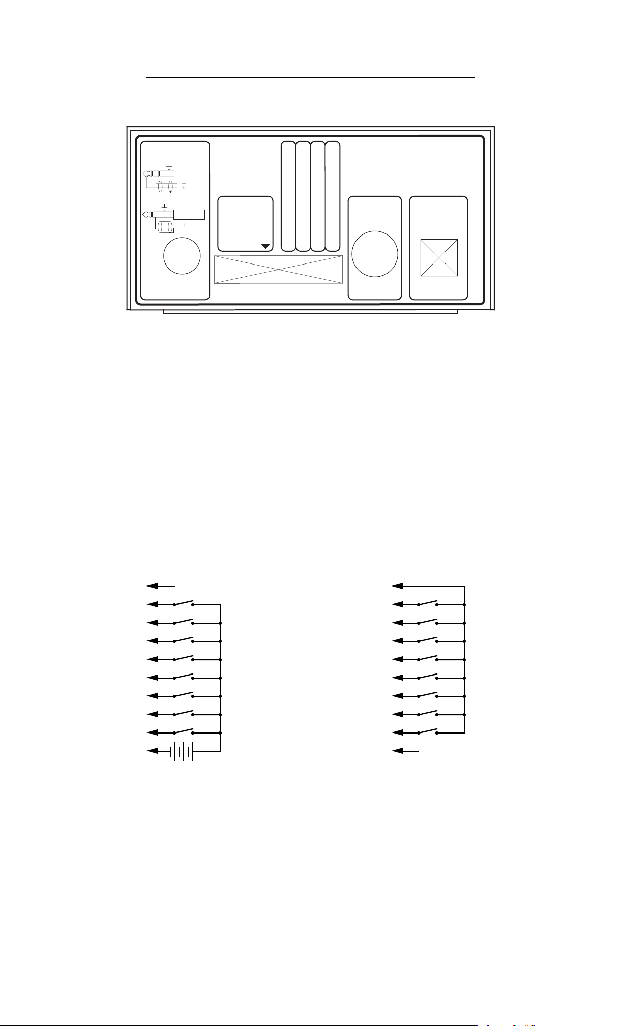
Front Panel Adjustments, Inputs & Indicators:
Several adjustments and indicators are available on the front panels of
the AB-100, AB-Clock, DR-50 and AB-50. The front of an AB-100 or AB-Clock
is shown below:
AB-100 AudioBrick
Gilderfluke & Co.
Glendale, California
Heart
Volume
Treble
Bass
Running
Delaying
Start Inputs
Set
Clock
Date
Check
Start
Manual
Adjustments:
The following adjustments are available on all of our Digital Audio
Repeaters:
Volume: This control sets the volume of the output from the Repeater.
This adjustment is available on the AB-100, AB-Clock, DR-50 and AB-
50.
Treble: This control is used to adjust the level of the high end of the
Shelving Equalizer. This adjustment is available on the AB-100, ABClock, DR-50 and AB-50.
Bass: This control is used to adjust the level of the low end of the
Shelving Equalizer. This adjustment is available on the AB-100, ABClock, DR-50 and AB-50.
Inputs:
The 'Manual Start' Button on the front of each AB-100 or AB-Clock feeds
directly into the Digital Audio Repeater's circuitry, and so doesn't light the
'Start' LED. Other than this one detail, the Manual Start Button acts just like
any other 'Start' input. It can be configured identically.
ÔSet ClockÕ Button: An AB-Clock adds two additional recessed buttons
that are used to check and set the clock. You must use the end of a pencil
or paper clip to press this button. This button is used to set the clock. Each
time you press it, the minutes will be incremented by one. If the ÔCheck
DateÕ Button is held in when this button is pressed, then the hours will be incremented.
ÔCheck DateÕ Button: An AB-Clock adds two additional recessed buttons
that are used to check and set the clock. You must use the end of a pencil
or paper clip to press this button. This button is used to check the date. The
first single digit is the day of the week (1-7). If it is pressed in and held, the
ÔSet ClockÕ Button will advance the hours of the clock each time it is
pressed.
ÔDefault ReloadÕ Button: The AB-100 and AB-Clock have a button hidden inside the case which is used to reload the default configuration on the
repeater. It is labeled as DIPSW1-2. To use it you must:
a) Power down the AB-100 or AB-Clock. You should always do this by
unplugging the power supply from the wall rather than unplugging
the 5 pin DIN connector at the AB-100/AB-Clock.
b) Remove the AB-100 or AB-Clock case top.
10 of 72
Page 19

GILDERFLUKE & CO. ¥ 205 S. FLOWER ¥ BURBANK, CA 91502-2102 ¥ 818/840-9484 ¥ 800/776-5972 ¥ FAX 818/840-9485
c) Press and hold the button down while plugging the power supply
back into the wall.
d) After the repeater reboots, release the button.
d) Reassemble the AB-100/AB-Clock.
The defaults are now reloaded. You can reconfigure the AB-100/AB-Clock
through the serial port at address 00h operating at 9600 baud, no parity.
Indicators:
The 'Running' LED on the front of each Digital Audio Repeater shows
when each is currently running. When this LED is lit on the front, then sound
should be coming out the back. This indicator is available on the AB-100,
AB-Clock, DR-50 and AB-50.
The 'Start' LED on the front of each AB-100 or AB-Clock is actually a com-
bination of the two opto-isolated start inputs. This shows the actual start inputs' status as it is seen by the Digital Audio Repeater, and not a processed
version of them.
The ÔDelayÕ LED on the front of each AB-100 or AB-Clock shows when:
a) The repeater is performing a delayed start or the delay between
each iteration of a loop.
b) The repeater is skipping over a part of the audio that has been en-
coded in the Eproms as a moment of silence. You can tell when the
repeater is doing a Ôrunning delayÕ because the 'Running' LED will
also be lit at the same time.
LCD Display: AB-Clocks also have a LCD Display added to them which
is used to display and set the current time and calendar. This display normally shows the current time in twenty-four hour ÔmilitaryÕ time format.
Following the time, ÒdsÓ will be displayed if the clock is currently using daylight savings time. The clock will also display ÒmuteÓ if an external input is
keeping any sound from playing or ÒrunÓ if the time is currently between the
hours that have been set for automatic tolling.
Pressing the ÔCheck DateÕ Button will cause the display to momentarily
switch to displaying the day (1=Sunday through 7= Saturday) and date
(mm/dd/yy).
11 of 72
Page 20
GILDERFLUKE & CO. ¥ 205 S. FLOWER ¥ BURBANK, CA 91502-2102 ¥ 818/840-9484 ¥ 800/776-5972 ¥ FAX 818/840-9485
- AB-100 and AB-Clock Connections -
The connections to the AB-100 and AB-Clock are identical. See the sec-
tions of this manual that cover the AB-50 and DR-50 for their connections.
Line Level Out
Balanced Output
R-T+ S
}
Unbalanced Output
T+ S
gnd
gnd
}
Amp
Amp
Aux. Port
1/4 J6 In
Input 'B'
Input 'A'
1
AB-100 AudioBrick
Gilderfluke & Co.
Glendale, California
Common
Power
Supply
Status Output
RS-422
Serial Port
Line Level Output:
The output of the AB-100 and AB-Clock is a +10 dB balanced output.
The connection is through a 1/4Ó stereo phone plug. If this output is operated in single ended mode, the unused output MUST be grounded. If it is not,
then the output will be excessively noisy. As shown by the illustration on the
end of the case, using a mono 1/4Ó phone plug will automatically ground
this unused output in single ended applications. Use a 1/4Ó stereo phone
plug only in balanced applications.
Aux. Port & 1/4-J6 Input:
The AUX PORT is used to select a specific spiel on a single AB-100 or AB-
Clock. You will need to select the OP-100 AUX PORT OPTO-ISOLATOR option if
you want to use the Aux. port. The input to the Aux. Port is the same 1/4 J-6
connection used by all of our Animation Control Systems. If you are using a
source other than our Animation Control Systems, the connections are as
follows:
(Brown) PIN #1
(red) PIN #2
(orange) PIN #3
(yellow) PIN #4
(green) PIN #5
(blue) PIN #6
(violet) PIN #7
(grey) PIN #8
(white) PIN #9
(black) PIN #10
+
GROUND (not used)
DATA BIT 7
DATA BIT 6
DATA BIT 5
DATA BIT 4
DATA BIT 3
DATA BIT 2
DATA BIT 1
DATA BIT 0
+ 5 to 24 VDC SUPPLY
(Brown) PIN #1
(red) PIN #2
(orange) PIN #3
(yellow) PIN #4
(green) PIN #5
(blue) PIN #6
(violet) PIN #7
(grey) PIN #8
(white) PIN #9
(black) PIN #10
GROUND
DATA BIT 7
DATA BIT 6
DATA BIT 5
DATA BIT 4
DATA BIT 3
DATA BIT 2
DATA BIT 1
DATA BIT 0
SUPPLY (not used)
Internal PowerExternal Power
JP-11 is used to select whether the 1/4-J6 input is to be run from external
power or from the same power supply as the AB-100 or AB-Clock. With JP-11
in the Left position, the inputs use same power supply as the AB-100 or ABClock. Any switch closure between the data bits and ground will trigger a
spiel. With JP-11 in the Right position, an external source of power is needed
by the 1/4-J6 input. This is the safer method of operating this port, since any
spikes on these input lines wonÕt be coupled into the AB-100/AB-Clock
through its power supply. The input to the 1/4 J-6 connection is simply eight
opto-isolators. Each input is equivalent to turning on a LED with a 4.7 Kohm
in series.
12 of 72
Page 21
GILDERFLUKE & CO. ¥ 205 S. FLOWER ¥ BURBANK, CA 91502-2102 ¥ 818/840-9484 ¥ 800/776-5972 ¥ FAX 818/840-9485
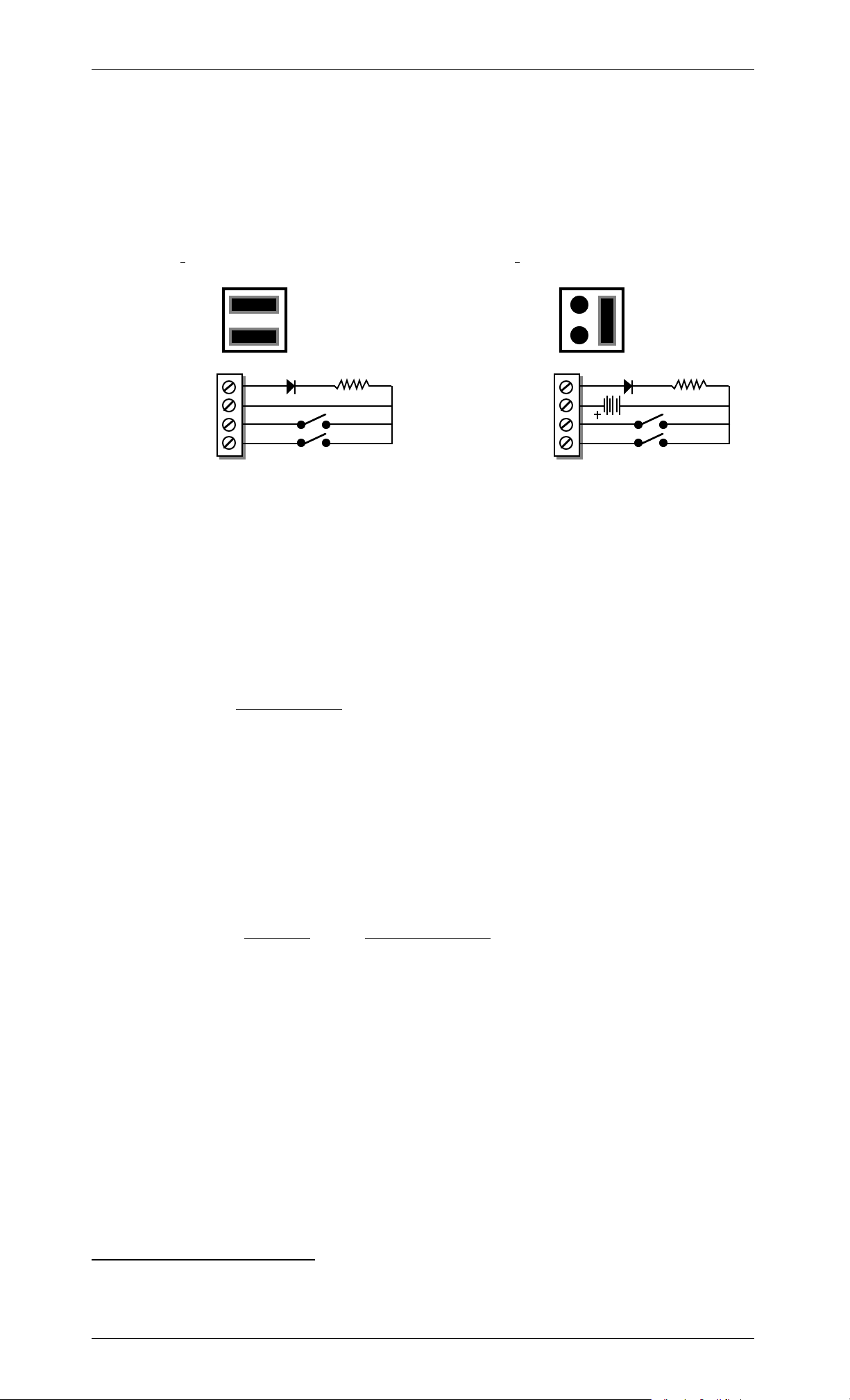
Start Inputs and Status Outputs:
Both the 'start' inputs and 'status' output for the AB-100 or AB-Clock are
optically isolated from all other parts of the system. Connections are made
through four screw terminals on the back of the AB-100 or AB-Clock. They
can be configured to run either from the same power as the AB-100 or ABClock or from external power supply. The jumper selection and connections
for these two modes of operation are as follows:
INTERNAL POWER EXTERNAL POWER
2.2KΩ
'S
'C
B I
NPUT 'RESTART'
NPUT ' START'
A I
TATUS '
OMMON'
2.2KΩ
'S
'C
B I
NPUT 'RESTART'
NPUT ' START'
A I
TATUS '
OMMON'
In the vast majority of cases, the ÔEXTERNALÕ power configuration is preferred, as it isolates the audio circuitry inside the AB-Clock from any possible
interference from the wires leading to your switches.
Power Supply:
Five position 180¡ DIN connector 2. Plugging and unplugging this connector from the AB-100/AB-Clock is not recommended while the power supply is plugged in. You should always unplug the power supply from the wall
before plugging/unplugging the 5 pin DIN connector at the AB-100/ABClock. The pinout for the Power Supply connector is as follows:
SIGNAL NAME:
Pin #1 Ground
Pin #2 N/C
Pin #3 + 5 VDC
Pin #4 - 12 to 15 VDC
Pin #5 + 12 to 15 VDC
RS-422 Serial Port:
For AB-100 and AB-Clocks, a six position RJ-11 (modular telephone style
connector) is used for the serial data. Facing the end of the cable with the
release latch upwards, its pin out is as follows:
COLOR
SIGNAL NAME:
LEFT WHITE SIGNAL GROUND
BLACK - SERIAL DATA OUT FROM REPEATER
RED + SERIAL DATA OUT FROM REPEATERS
GREEN - SERIAL DATA IN TO REPEATERS
YELLOW + SERIAL DATA IN TO REPEATERS
RIGHT BLUE SIGNAL GROUND
To communicate with the AB-100 and AB-Clocks through the serial port,
you can use just about any computer or terminal that has a serial port on it.
Some newer computer designs, like the Apple Macintosh, come with serial
ports that are directly compatible with the RS-422/RS-485 signal levels the
AB-100 and AB-Clocks want to see. These signal levels are close enough to
be used with the RS-232 signal levels found on most older computers (like
all IBM PCs and compatibles). They can be attached with only a simple
2 Use extreme caution when making discrete wire connections to this connection! Five
pin 180¡ DIN connectors are numbered 3, 5, 2, 4, 1 as you face the socket on the outside of the AudioBrick.
13 of 72
Page 22

GILDERFLUKE & CO. ¥ 205 S. FLOWER ¥ BURBANK, CA 91502-2102 ¥ 818/840-9484 ¥ 800/776-5972 ¥ FAX 818/840-9485
adapter cable, so long as the wire isn't too long and there arenÕt too many
AB-100s and AB-Clocks attached to the same serial line. To gain the full advantage of the RS-422/RS-485 signal levels (multidrop networking, distances
of up to a mile) you will need to use a signal level adapter.
To cross wire the RS-422/RS-485 signals from the digital audio system to
the RS-232 serial port of an IBM compatible, cross connect the signals as
follows:
DB-25
DE-9 SIGNAL SIGNAL FROM/TO AUDIO SYSTEM
2 3 DATA OUT - SERIAL DATA IN TO REPEATERS (GREEN)
3 2 DATA IN - SERIAL DATA OUT FROM REPEATER
(BLACK)
7 5 GROUND SIGNAL GROUND (BLUE or WHITE)
Apple Macintosh computers have true RS-422 serial ports built in. To connect to the digital audio system, the pin out is as follows (view is of connector on the outside of a Macintosh):
from + serial data out from repeaters (red)
from - serial data out from repeaters (black)
678
345
12
to + serial data in to repeaters (yellow)
to - serial data in to repeaters (green)
signal ground (white or blue)
14 of 72
Page 23

GILDERFLUKE & CO. ¥ 205 S. FLOWER ¥ BURBANK, CA 91502-2102 ¥ 818/840-9484 ¥ 800/776-5972 ¥ FAX 818/840-9485
- AB-100 AudioBrick Configuration -
To configure the system through the serial port, you need to connect the
system just as you do for any serial communications (see the 'AB-100
AudioBrick Serial Port Commands' section of the manual). The configuration
mode is entered by the command:
"m" (5AA5) (TRACK#)
This command will bring up the following menu from the Repeater which
was addressed.
EXAMPLE: to bring up the configuration screen for a card addressed as
Ôtrack 00Õ (this is the normal default configuration address when a Repeater
is shipped): m5AA500
This would bring up the following configuration screen (the screen shown
is the default configuration):
-MACs DIGITAL AUDIO SYSTEM revision 1.12 copyright 1991 GILDERFLUKE & Co. DCM-
a) Channel number- 00 | g) Select from AUX- yes | l) #1 PA station- 01
b) Baud rate- 9600 | h) Direct select- yes | m) #2 PA station- 02
c) Odd parity- no | i) Mute if stopped- no | o) Std PA priorities- no
d) EPROM type- 27C010 | j) Start delay- 0010 | p) Zone Priorities- no
e) Inputs Debounce- 0A | k) Early starts- Jmp Fwd | q) Loop all mode- no
f) DR-400 mode- no | X) exit
1 2 3 4 5 6 7 8
G) Group assignments: | 1 | 0 | 0 | 0 | 0 | 0 | 0 | F |
H) PA Zones Enabled: | 0 | 1 | 2 | 3 | 4 | 5 | 6 | 7 |
I) Half Mute Zones Enabled: |yes|___|___|___|___|___|___|___|
J) Full Mute Zones Enabled: |yes|___|___|___|___|___|___|___|
STOP
INPUT and EDGE HALF MUTE UN STOP RESET START LOOP AT END
K) A input Closing: |______|______|______|______|______|__on__|______|______|
L) A input Opening: |______|______|______|______|______|______|______|______|
M) B input Closing: |______|__on__|______|__on__|______|______|______|______|
O) B input Opening: |______|______|__on__|______|______|______|______|______|
P) PB input Closing: |__on__|______|______|______|__on__|__on__|______|______|
Q) PB input Opening: |______|______|__on__|______|______|______|______|______|
R) Aux input Closing:|______|______|______|______|______|______|__on__|______|
S) Aux input Opening:|______|______|______|______|______|______|______|______|
Enter command- _
The (5AA5) part of the command is a key to keep this mode from being
inadvertently entered. The card addressed by the TRACK# will put a configuration menu on the screen. When this mode is entered by any card, it disables all of the other serial commands on all the cards in the system. As with
the normal serial command mode, the upper and lower 'case' of all input
is important. An 'a' is a command while an 'A' is a number. All numeric values are entered in HEX (0 - 9, A - F).
If another command is entered while the last command is waiting for
additional input, the new command will be started. If at any point you
enter a command in error and it is waiting for additional input, you can
leave the command by entering an <ESC>ape key. With the exception of
the GROUP ENABLE and PA ZONE ENABLE commands, this will leave the original configuration unaltered. These two commands will only be changed up
to the point where you <ESC>aped.
If you want to keep a hard copy printout of the current configuration of
15 of 72
Page 24

GILDERFLUKE & CO. ¥ 205 S. FLOWER ¥ BURBANK, CA 91502-2102 ¥ 818/840-9484 ¥ 800/776-5972 ¥ FAX 818/840-9485
any card, you should use the <ESC>ape key to redraw the screen while
saving the print in the modem program running on your computer. This file
can then be printed out at any time.
Note that only one card in the entire system is allowed to be in configuration mode at one time. For this reason, if you try to put a card which doesnÕt
exist into configuration mode, not only will you not see a configuration
screen from that nonexistent card, no other card in the system will want to
listen to you until you take the nonexistent card out of configuration mode.
To do this, type a: x n
The other cards will then start listening to you again.
The AB-100 and AB-Clock have a button hidden inside the case which is
used to reload the default configuration on the repeater. It is labeled as
DIPSW1-2. To use it you must:
a) Power down the AB-100 or AB-Clock. You should always do this by
unplugging the power supply from the wall rather than unplugging
the 5 pin DIN connector at the AB-100/AB-Clock.
b) Remove the AB-100 or AB-Clock case top.
c) Press and hold the button down while plugging the power supply
back into the wall.
d) After the repeater reboots, release the button.
d) Reassemble the AB-100/AB-Clock.
The defaults are now reloaded. You can reconfigure the AB-100/AB-Clock
through the serial port at address 00h operating at 9600 baud, no parity.
¥¥¥¥¥¥¥¥¥¥¥¥¥¥¥¥¥¥¥¥¥¥¥¥¥¥¥¥¥¥¥¥¥¥¥¥¥¥¥¥¥¥¥¥¥¥¥¥¥¥¥¥¥¥¥¥¥¥¥¥¥¥¥¥¥¥¥¥¥¥¥¥¥¥¥¥¥¥¥¥¥¥¥¥¥¥¥¥¥¥¥¥¥¥¥¥¥¥¥¥¥¥¥¥¥¥¥¥¥¥¥¥¥¥¥¥¥¥¥
"a" Enter Track Number:
This command is used to tell the card which addresses it should respond
to from the serial commands. No two cards in the system should have the
same address assigned to them. When loaded with the default configuration, the address assigned to a card is 00. If more than one card is
used in the system, they should be plugged in one at a time and have their
addresses changed. Once it has been changed, each card can stay
plugged in the card cage.
¥¥¥¥¥¥¥¥¥¥¥¥¥¥¥¥¥¥¥¥¥¥¥¥¥¥¥¥¥¥¥¥¥¥¥¥¥¥¥¥¥¥¥¥¥¥¥¥¥¥¥¥¥¥¥¥¥¥¥¥¥¥¥¥¥¥¥¥¥¥¥¥¥¥¥¥¥¥¥¥¥¥¥¥¥¥¥¥¥¥¥¥¥¥¥¥¥¥¥¥¥¥¥¥¥¥¥¥¥¥¥¥¥¥¥¥¥¥¥
"b" Baud Rate:
The serial port on each Repeater card can support any of the following
baud rates:
1) 110
2) 150
3) 300
4) 600
5) 1200
6) 2400
7) 4800
8) 9600 (default value)
9) 19,200
10) 48,000
11) 96,000
The lower baud rates may require that the dead man circuit will need to
be disconnected (U-7 pin #6) while in configuration mode. The reason for
this is that the dead man needs to be updated about once a second, and
at the lowest baud rates it will be spending so much time printing that it will
time out and reset the system. 9600 baud is an average speed to run the
16 of 72
Page 25

GILDERFLUKE & CO. ¥ 205 S. FLOWER ¥ BURBANK, CA 91502-2102 ¥ 818/840-9484 ¥ 800/776-5972 ¥ FAX 818/840-9485
system.
All cards in the system must be set to the same baud rate. The default
speed is 9600 baud. This command doesn't take effect until you enter the
eXit command.
¥¥¥¥¥¥¥¥¥¥¥¥¥¥¥¥¥¥¥¥¥¥¥¥¥¥¥¥¥¥¥¥¥¥¥¥¥¥¥¥¥¥¥¥¥¥¥¥¥¥¥¥¥¥¥¥¥¥¥¥¥¥¥¥¥¥¥¥¥¥¥¥¥¥¥¥¥¥¥¥¥¥¥¥¥¥¥¥¥¥¥¥¥¥¥¥¥¥¥¥¥¥¥¥¥¥¥¥¥¥¥¥¥¥¥¥¥¥¥
"c" Odd Parity Toggle:
This toggle enables the ODD PARITY data check on the serial port for this
Repeater. Parity is a method of confirming that the data sent to the audio
system arrives intact. Any data that gets jumbled is ignored. If ODD PARITY is
enabled, it must be enabled on all the cards in the system as well as on
your computer or terminal. The default value for this command is off. This
command doesn't take effect until you enter the eXit command.
¥¥¥¥¥¥¥¥¥¥¥¥¥¥¥¥¥¥¥¥¥¥¥¥¥¥¥¥¥¥¥¥¥¥¥¥¥¥¥¥¥¥¥¥¥¥¥¥¥¥¥¥¥¥¥¥¥¥¥¥¥¥¥¥¥¥¥¥¥¥¥¥¥¥¥¥¥¥¥¥¥¥¥¥¥¥¥¥¥¥¥¥¥¥¥¥¥¥¥¥¥¥¥¥¥¥¥¥¥¥¥¥¥¥¥¥¥¥¥
"d" Eprom Type:
If the repeater is playing snippets of the sound you have burnt into a set
of Eproms and repeats each section 2, 4 or 8 times, then this variable is set
improperly for the type of Eproms you have installed. The following types of
Eproms are currently supported by the digital audio Repeaters Repeaters:
27C512
27C010 (default setting)
27C020
27C040
27C080
All the Eproms on a card must be of the same type. Different cards in the
same system can each have different types of Eproms on them. This command doesn't take effect until the eXit command is completed.
¥¥¥¥¥¥¥¥¥¥¥¥¥¥¥¥¥¥¥¥¥¥¥¥¥¥¥¥¥¥¥¥¥¥¥¥¥¥¥¥¥¥¥¥¥¥¥¥¥¥¥¥¥¥¥¥¥¥¥¥¥¥¥¥¥¥¥¥¥¥¥¥¥¥¥¥¥¥¥¥¥¥¥¥¥¥¥¥¥¥¥¥¥¥¥¥¥¥¥¥¥¥¥¥¥¥¥¥¥¥¥¥¥¥¥¥¥¥¥
"e" Inputs Debounce:
This command allows you to set the number of times the software inside
the Digital Audio Repeater will check any inputs before it actually believes a
change has happened. A typical value is 0A. If you experience multiple
triggers on any input, just raise this number until the problem disappears.
¥¥¥¥¥¥¥¥¥¥¥¥¥¥¥¥¥¥¥¥¥¥¥¥¥¥¥¥¥¥¥¥¥¥¥¥¥¥¥¥¥¥¥¥¥¥¥¥¥¥¥¥¥¥¥¥¥¥¥¥¥¥¥¥¥¥¥¥¥¥¥¥¥¥¥¥¥¥¥¥¥¥¥¥¥¥¥¥¥¥¥¥¥¥¥¥¥¥¥¥¥¥¥¥¥¥¥¥¥¥¥¥¥¥¥¥¥¥¥
"f" DR-400 Mode:
NOT USED WITH AB-100 AudioBrick: This toggle should only be turned on
only when operating on a DR-400 Audio Processing Cards. It disables all of
the commands which DR-400Õs canÕt (or shouldnÕt) use. This saves you the
time of turning all of these off individually.
¥¥¥¥¥¥¥¥¥¥¥¥¥¥¥¥¥¥¥¥¥¥¥¥¥¥¥¥¥¥¥¥¥¥¥¥¥¥¥¥¥¥¥¥¥¥¥¥¥¥¥¥¥¥¥¥¥¥¥¥¥¥¥¥¥¥¥¥¥¥¥¥¥¥¥¥¥¥¥¥¥¥¥¥¥¥¥¥¥¥¥¥¥¥¥¥¥¥¥¥¥¥¥¥¥¥¥¥¥¥¥¥¥¥¥¥¥¥¥
"g" Select From Aux.:
If more than one recording is stored on a single Digital Audio Repeater
card, each separate recording is referred to as a spiel. Each spiel can be
accessed individually and played back. Up to 255 of these spiels can be
stored on a single Digital Audio Repeater card. These requests can be
made through the serial port or through the AUX PORT.
This toggle enables the auxiliary port for requesting the spiels on this card.
There are two methods of selecting spiels from the AUX PORT. Which one is
used is selected by the next command.
¥¥¥¥¥¥¥¥¥¥¥¥¥¥¥¥¥¥¥¥¥¥¥¥¥¥¥¥¥¥¥¥¥¥¥¥¥¥¥¥¥¥¥¥¥¥¥¥¥¥¥¥¥¥¥¥¥¥¥¥¥¥¥¥¥¥¥¥¥¥¥¥¥¥¥¥¥¥¥¥¥¥¥¥¥¥¥¥¥¥¥¥¥¥¥¥¥¥¥¥¥¥¥¥¥¥¥¥¥¥¥¥¥¥¥¥¥¥¥
"h" Direct Select:
17 of 72
Page 26

GILDERFLUKE & CO. ¥ 205 S. FLOWER ¥ BURBANK, CA 91502-2102 ¥ 818/840-9484 ¥ 800/776-5972 ¥ FAX 818/840-9485
This command is used to switch the AUX PORT between selecting directly
(1 of 8) instead of using binary inputs for requesting up to 255 different
spiels. The direct select is useful when you have eight or less spiels which
need to be called up through the AUX PORT. The AUX PORT can be wired directly to up to eight different pushbuttons. When any of these buttons are
pressed it will select the appropriate spiel. The first button pushed will be
played at the next start or looping command, unless it is overridden by another spiel request from the serial ports. (The board can also be told to start
playing the newly requested spiel immediately if you set the EARLY STARTS
option to either 'jump forward' or 'jump back'.)
If this mode is off, then up to 255 different spiels can be selected through
the AUX PORT. The AUX PORT can be connected directly to the output of a
computer or animation control system. If you need to connect it to pushbuttons, you will need to use diodes or a keyboard encoder to encode a binary
number to be sent to the AUX PORT.
As with changes in inputs on the A, B, or PB input, changes on the AUX
PORT can be used to start, stop, or whatever a card. If the direct select option is 'on', then a rising edge is on any new arrival of a new closure, and a
falling edge is when all input lines are opened. If the direct selection is 'off',
then a rising edge is on any change in the AUX PORT except for when all of
the inputs go open, which is considered to be a falling edge.
This option defaults to an 'on' condition.
¥¥¥¥¥¥¥¥¥¥¥¥¥¥¥¥¥¥¥¥¥¥¥¥¥¥¥¥¥¥¥¥¥¥¥¥¥¥¥¥¥¥¥¥¥¥¥¥¥¥¥¥¥¥¥¥¥¥¥¥¥¥¥¥¥¥¥¥¥¥¥¥¥¥¥¥¥¥¥¥¥¥¥¥¥¥¥¥¥¥¥¥¥¥¥¥¥¥¥¥¥¥¥¥¥¥¥¥¥¥¥¥¥¥¥¥¥¥¥
"i" Mute if Stopped:
This toggle allows you to tell an AB-100 to mute all the audio when the
Repeater is stopped. This can be used if the mix inputs to the card aren't
used for anything else. This defaults to a 'off' condition.
¥¥¥¥¥¥¥¥¥¥¥¥¥¥¥¥¥¥¥¥¥¥¥¥¥¥¥¥¥¥¥¥¥¥¥¥¥¥¥¥¥¥¥¥¥¥¥¥¥¥¥¥¥¥¥¥¥¥¥¥¥¥¥¥¥¥¥¥¥¥¥¥¥¥¥¥¥¥¥¥¥¥¥¥¥¥¥¥¥¥¥¥¥¥¥¥¥¥¥¥¥¥¥¥¥¥¥¥¥¥¥¥¥¥¥¥¥¥¥
"j" Start Delay:
This command is used to set the START DELAY for this card. If the START
DELAY is anything other than 0000, then any start which follows a reset will
cause the Repeater to delay for the time set by the START DELAY until it actually starts the Repeater. This is useful in applications where a single start
input can be used to start a number of different cards, with the actual starting time of each of the cards set by the delay time. The actual amount of
delay time can be adjusted using the START DELAY in the field.
The START DELAY is also used when a Repeater is in looping mode. In be-
tween each loop, the Repeater delays by the amount of time set by the
START DELAY. This allows you to record a fairly short announcement which
needs to repeat all day long. The START DELAY can be used to set how often
this spiel repeats. Again, the amount of delay can be adjusted in the field
as needed.
Each count of the START DELAY is equal to .029127111 seconds. This al-
lows you to set the delay from about 1/34th of a second on up to about 1/2
hour.
To determine the value you need to use for a particular delay:
1) Divide the number of seconds you want to delay by
.029127111.
2) Round the result off to the nearest whole number.
3) Convert result to HEX (a HEX calculator makes this easier).
This feature defaults to a value of 0010. Acceptable input range for the
delay is 0000 to FFFF. A 0000 input disables this option.
18 of 72
Page 27

GILDERFLUKE & CO. ¥ 205 S. FLOWER ¥ BURBANK, CA 91502-2102 ¥ 818/840-9484 ¥ 800/776-5972 ¥ FAX 818/840-9485
¥¥¥¥¥¥¥¥¥¥¥¥¥¥¥¥¥¥¥¥¥¥¥¥¥¥¥¥¥¥¥¥¥¥¥¥¥¥¥¥¥¥¥¥¥¥¥¥¥¥¥¥¥¥¥¥¥¥¥¥¥¥¥¥¥¥¥¥¥¥¥¥¥¥¥¥¥¥¥¥¥¥¥¥¥¥¥¥¥¥¥¥¥¥¥¥¥¥¥¥¥¥¥¥¥¥¥¥¥¥¥¥¥¥¥¥¥¥¥
"k" Early Starts:
The user has the choice of what each card does when it is still playing a
spiel and receives a new 'start' or 'loop' command. The options are:
1) DO NOTHING.
2) JUMP FORWARD to the next spiel.
3) JUMP BACKWARDS to the start of the current spiel.
4) BANK START so that it won't be acted upon until the current
spiel finishes.
The JUMP FORWARD and JUMP BACKWARDS commands have the lowest
priority of all possible spiel requests. Any serial port or AUX PORT spiel request
will take priority over these commands.
This feature defaults to a setting of 'JUMP FORWARD'.
¥¥¥¥¥¥¥¥¥¥¥¥¥¥¥¥¥¥¥¥¥¥¥¥¥¥¥¥¥¥¥¥¥¥¥¥¥¥¥¥¥¥¥¥¥¥¥¥¥¥¥¥¥¥¥¥¥¥¥¥¥¥¥¥¥¥¥¥¥¥¥¥¥¥¥¥¥¥¥¥¥¥¥¥¥¥¥¥¥¥¥¥¥¥¥¥¥¥¥¥¥¥¥¥¥¥¥¥¥¥¥¥¥¥¥¥¥¥¥
"l" #1 Priority PA Station:
NOT USED WITH AB-100 AudioBrick: In the Public Address System there
are a number of different ways to assign priorities to different PA STATIONS
and PA zones. This command allows you to assign a single PA STATION as the
top priority PA STATION. Any valid PA requests made by the top priority PA
STATION will be honored by this card at the exclusion of any other PA requests. The top and second priority PA STATION assignments are usually
given to either a PA STATION which is local to the speakers which are controlled by this card, or to a PA STATION from which safety announcements
will be made.
The top priority PA STATION defaults to a value of 01. Acceptable input
range is from 00 to FF.
¥¥¥¥¥¥¥¥¥¥¥¥¥¥¥¥¥¥¥¥¥¥¥¥¥¥¥¥¥¥¥¥¥¥¥¥¥¥¥¥¥¥¥¥¥¥¥¥¥¥¥¥¥¥¥¥¥¥¥¥¥¥¥¥¥¥¥¥¥¥¥¥¥¥¥¥¥¥¥¥¥¥¥¥¥¥¥¥¥¥¥¥¥¥¥¥¥¥¥¥¥¥¥¥¥¥¥¥¥¥¥¥¥¥¥¥¥¥¥
"m" #2 Priority PA Station:
NOT USED WITH AB-100 AudioBrick: In the Public Address System there
are a number of different ways to assign priorities to different PA STATIONS
and PA zones. This command allows you to assign a single PA STATION as the
second priority PA STATION. Any valid PA requests made by the second priority PA STATION will be honored by this card at the exclusion of any other PA
requests except those from the top PA STATION. The top and second priority
PA STATION assignments are usually given to either a PA STATION which are
local to the speakers which are controlled by this card, or to a PA STATION
from which safety announcements will be made.
The second priority PA STATION defaults to a value of 02. Acceptable
input range is from 00 to FF.
¥¥¥¥¥¥¥¥¥¥¥¥¥¥¥¥¥¥¥¥¥¥¥¥¥¥¥¥¥¥¥¥¥¥¥¥¥¥¥¥¥¥¥¥¥¥¥¥¥¥¥¥¥¥¥¥¥¥¥¥¥¥¥¥¥¥¥¥¥¥¥¥¥¥¥¥¥¥¥¥¥¥¥¥¥¥¥¥¥¥¥¥¥¥¥¥¥¥¥¥¥¥¥¥¥¥¥¥¥¥¥¥¥¥¥¥¥¥¥
"o" Standard PA Priorities:
NOT USED WITH AB-100 AudioBrick: In the Public Address System there
are a number of different ways to assign priorities to different PA STATIONS
and PA zones. If STANDARD and ZONE PRIORITIES are both off, then all valid
PA requests (from PA STATIONS other than the top and second priority PA STATIONS for this card) will be treated equally. Any valid request will be honored, and if more than one valid request comes in to the same card, they
will simply be mixed.
If the STANDARD PA PRIORITY option is 'on', then PA STATIONS with higher
numbers will take priority over those with lower numbers. Only one PA request will be honored at one time.
19 of 72
Page 28

GILDERFLUKE & CO. ¥ 205 S. FLOWER ¥ BURBANK, CA 91502-2102 ¥ 818/840-9484 ¥ 800/776-5972 ¥ FAX 818/840-9485
This feature defaults to an 'off' condition.
¥¥¥¥¥¥¥¥¥¥¥¥¥¥¥¥¥¥¥¥¥¥¥¥¥¥¥¥¥¥¥¥¥¥¥¥¥¥¥¥¥¥¥¥¥¥¥¥¥¥¥¥¥¥¥¥¥¥¥¥¥¥¥¥¥¥¥¥¥¥¥¥¥¥¥¥¥¥¥¥¥¥¥¥¥¥¥¥¥¥¥¥¥¥¥¥¥¥¥¥¥¥¥¥¥¥¥¥¥¥¥¥¥¥¥¥¥¥¥
"p" PA Zone Priorities:
NOT USED WITH AB-100 AudioBrick: In the Public Address System there
are a number of different ways to assign priorities to different PA STATIONS
and PA zones. If STANDARD and ZONE PRIORITIES are both off, then all valid
PA requests (from PA STATIONS other than the top and second priority PA STATIONS for this card) will be treated equally. Any valid request will be honored, and if more than one valid request comes in to the same card, they
will simply be mixed.
If the PA ZONE PRIORITY option is 'on', then PA zone requests with higher
numbers will take priority over those with lower numbers. Only one PA request will be honored at one time.
This feature defaults to an 'off' condition.
¥¥¥¥¥¥¥¥¥¥¥¥¥¥¥¥¥¥¥¥¥¥¥¥¥¥¥¥¥¥¥¥¥¥¥¥¥¥¥¥¥¥¥¥¥¥¥¥¥¥¥¥¥¥¥¥¥¥¥¥¥¥¥¥¥¥¥¥¥¥¥¥¥¥¥¥¥¥¥¥¥¥¥¥¥¥¥¥¥¥¥¥¥¥¥¥¥¥¥¥¥¥¥¥¥¥¥¥¥¥¥¥¥¥¥¥¥¥¥
"q" Loop All:
Under normal looping mode, a single spiel will repeat over and over
again. If this feature is 'on', all the spiels recorded on a single card will be
played in a loop. A delay, if enabled, will be inserted between each individual spiel.
This feature defaults to an 'off' condition.
¥¥¥¥¥¥¥¥¥¥¥¥¥¥¥¥¥¥¥¥¥¥¥¥¥¥¥¥¥¥¥¥¥¥¥¥¥¥¥¥¥¥¥¥¥¥¥¥¥¥¥¥¥¥¥¥¥¥¥¥¥¥¥¥¥¥¥¥¥¥¥¥¥¥¥¥¥¥¥¥¥¥¥¥¥¥¥¥¥¥¥¥¥¥¥¥¥¥¥¥¥¥¥¥¥¥¥¥¥¥¥¥¥¥¥¥¥¥¥
"G" Group Assignments:
When using the serial port to control the audio system, you have the
choice of using a number of commands (start, stop, etc.) which select only
a single 'group' of cards. This command is used to select which of 12
GROUP ASSIGNMENTS this card will respond to.
Acceptable input range for GROUP ASSIGNMENTS are from 0 to F. If you
need less than 12 GROUPS, you should assign the unused spaces to any of
the group numbers you have already used.
¥¥¥¥¥¥¥¥¥¥¥¥¥¥¥¥¥¥¥¥¥¥¥¥¥¥¥¥¥¥¥¥¥¥¥¥¥¥¥¥¥¥¥¥¥¥¥¥¥¥¥¥¥¥¥¥¥¥¥¥¥¥¥¥¥¥¥¥¥¥¥¥¥¥¥¥¥¥¥¥¥¥¥¥¥¥¥¥¥¥¥¥¥¥¥¥¥¥¥¥¥¥¥¥¥¥¥¥¥¥¥¥¥¥¥¥¥¥¥
"H" PA Zone Enables:
NOT USED WITH AB-100 AudioBrick: You can tell any card in the system
to respond to up to 8 different PA zone requests. This command is used to
tell the card which zones it should respond to. Any PA requests to a zone
other than ones which has been assigned to it will be ignored by this card.
Acceptable input range for ZONE ASSIGNMENTS are from 00 to FF. If you
need less than 8 ZONES, you should assign the unused spaces to any of the
PA ZONE numbers to FF.
¥¥¥¥¥¥¥¥¥¥¥¥¥¥¥¥¥¥¥¥¥¥¥¥¥¥¥¥¥¥¥¥¥¥¥¥¥¥¥¥¥¥¥¥¥¥¥¥¥¥¥¥¥¥¥¥¥¥¥¥¥¥¥¥¥¥¥¥¥¥¥¥¥¥¥¥¥¥¥¥¥¥¥¥¥¥¥¥¥¥¥¥¥¥¥¥¥¥¥¥¥¥¥¥¥¥¥¥¥¥¥¥¥¥¥¥¥¥
"I" Half-Mute Zone Enables:
NOT USED WITH AB-100 AudioBrick: There are eight HALF-MUTE zones
available in the Digital Audio System. This command is used to select which
of the eight, if any, you wish to use. Any HALF-MUTE request for an enabled
HALF-MUTE ZONE will half-mute this card.
¥¥¥¥¥¥¥¥¥¥¥¥¥¥¥¥¥¥¥¥¥¥¥¥¥¥¥¥¥¥¥¥¥¥¥¥¥¥¥¥¥¥¥¥¥¥¥¥¥¥¥¥¥¥¥¥¥¥¥¥¥¥¥¥¥¥¥¥¥¥¥¥¥¥¥¥¥¥¥¥¥¥¥¥¥¥¥¥¥¥¥¥¥¥¥¥¥¥¥¥¥¥¥¥¥¥¥¥¥¥¥¥¥¥¥¥¥¥¥
"J" Full-Mute Zone Enables:
There are eight FULL-MUTE zones available in the Digital Audio System.
This command is used to select which of the eight, if any, you wish to use.
Any FULL-MUTE request for an enabled FULL-MUTE ZONE will mute this card.
20 of 72
Page 29

GILDERFLUKE & CO. ¥ 205 S. FLOWER ¥ BURBANK, CA 91502-2102 ¥ 818/840-9484 ¥ 800/776-5972 ¥ FAX 818/840-9485
¥¥¥¥¥¥¥¥¥¥¥¥¥¥¥¥¥¥¥¥¥¥¥¥¥¥¥¥¥¥¥¥¥¥¥¥¥¥¥¥¥¥¥¥¥¥¥¥¥¥¥¥¥¥¥¥¥¥¥¥¥¥¥¥¥¥¥¥¥¥¥¥¥¥¥¥¥¥¥¥¥¥¥¥¥¥¥¥¥¥¥¥¥¥¥¥¥¥¥¥¥¥¥¥¥¥¥¥¥¥¥¥¥¥¥¥¥¥¥
Input Triggering:
"K" 'A' Input Closing Edge:
"L" 'A' Input Opening Edge:
"M" 'B' Input Closing Edge:
"O" 'B' Input Opening Edge:
"P" 'PB' Input Closing Edge:
"Q" 'PB' Input Opening Edge:
"R" 'Aux. Port' Input Closing Edge:
"S" 'Aux. Port' Input Opening Edge:
Each Digital Audio Repeater card has two opto-isolated external inputs,
one push button input on the front panel, and one AUX PORT input. These
commands are used to select what actions will take place on each edge of
each of these inputs. Note that both rising and falling edge actions are
available to the user. This allows you to do things like start a Repeater on a
closing edge and then stop it on the opening edge of the same input.
The closing edge on the 'A', 'B', and 'PB' inputs are considered to be
when a normally open push button or switch is closed. The opening edge is
when that same switch or push button is opened. A closing edge on the
AUX PORT is considered to be any of the eight inputs closing if the direct select option is 'on', or any change in the input (except going to all inputs
open) if the direct select option is off. An opening edge on the AUX PORT is
when all eight of the inputs go to an open condition.
The hardware for the 'A', 'B', and 'AUX PORT' inputs can be configured to
run from either an internal power supply and a simple switch closure, or
from an external power supply or powered output.
When each Digital Audio Repeater card resets or is first powered up, it
checks the conditions on all the inputs, inverts them, and then compares
them with the steady-state conditions of the inputs. What this means is that
on power-up, if an input you are using to tell a card to run is in the 'run'
condition, the system will start immediately.
If multiple inputs to the system arrive simultaneously, they have the following priorities:
1) 'AUX PORT" INPUTS
2) 'A' input
3) 'B' INPUT
4) 'PB' INPUT
This will probably happen only on power-up.
¥¥¥¥¥¥¥¥¥¥¥¥¥¥¥¥¥¥¥¥¥¥¥¥¥¥¥¥¥¥¥¥¥¥¥¥¥¥¥¥¥¥¥¥¥¥¥¥¥¥¥¥¥¥¥¥¥¥¥¥¥¥¥¥¥¥¥¥¥¥¥¥¥¥¥¥¥¥¥¥¥¥¥¥¥¥¥¥¥¥¥¥¥¥¥¥¥¥¥¥¥¥¥¥¥¥¥¥¥¥¥¥¥¥¥¥¥¥¥
"x" or "X" eXit Setup Mode:
This command is used to exit the setup mode. If you hit this command in
error, hitting an <ESC>ape key will get you back to the setup mode. All the
setup commands that don't take effect immediately, take effect when the
eXit command is entered. This includes things like the BAUD RATE, so you will
have to change the baud rate of the terminal you are using at this time.
The eXit command asks you if you want to save the current setup permanently. If you answer 'Y', the EEprom will be written with the current configuration. If you answer 'N', the setup mode will be exited without writing to the
EEprom.
All cards in the system have their serial ports disabled while any card in
the system is in setup mode. This is the only command to which they will respond. After the initial 'X', all of the other cards wait for a 'Y' or 'N' before
21 of 72
Page 30

GILDERFLUKE & CO. ¥ 205 S. FLOWER ¥ BURBANK, CA 91502-2102 ¥ 818/840-9484 ¥ 800/776-5972 ¥ FAX 818/840-9485
they will start accepting other serial commands again.
22 of 72
Page 31

GILDERFLUKE & CO. ¥ 205 S. FLOWER ¥ BURBANK, CA 91502-2102 ¥ 818/840-9484 ¥ 800/776-5972 ¥ FAX 818/840-9485
- AB-100 AudioBrick Summary of Setup Commands -
"a" ENTER TRACK NUMBER:
"b" BAUD RATE:
"c" ODD PARITY TOGGLE:
"d" Eprom TYPE:
"e" CLOCK ENABLED:
"g" SELECT FROM AUX:
"h" DIRECT SELECT:
"i" MUTE IF STOPPED:
"j" START DELAY:
"k" EARLY STARTS:
"l" #1 Priority PA Station:
"m" #2 Priority PA Station:
"o" STANDARD PA PRIORITIES:
"p" PA ZONE PRIORITIES:
"q" Loop All:
"G" GROUP ASSIGNMENTS:
"H" PA ZONE ENABLES:
"I" HALF-MUTE ZONE ENABLES:
"J" FULL-MUTE ZONE ENABLES:
"K" 'A' INPUT CLOSING EDGE:
"L" 'A' INPUT OPENING EDGE:
"M" 'B' INPUT CLOSING EDGE:
"O" 'B' INPUT OPENING EDGE:
"P" 'PB' INPUT CLOSING EDGE:
"Q" 'PB' INPUT OPENING EDGE:
"R" 'AUX PORT' INPUT CLOSING
EDGE:
"S" 'AUX PORT' INPUT OPENING
EDGE:
"x" or "X" eXit SETUP MODE:
23 of 72
Page 32

GILDERFLUKE & CO. ¥ 205 S. FLOWER ¥ BURBANK, CA 91502-2102 ¥ 818/840-9484 ¥ 800/776-5972 ¥ FAX 818/840-9485
another blank page
24 of 72
Page 33

GILDERFLUKE & CO. ¥ 205 S. FLOWER ¥ BURBANK, CA 91502-2102 ¥ 818/840-9484 ¥ 800/776-5972 ¥ FAX 818/840-9485
- AB-100 AudioBrick Serial Port Commands -
The MACs digital audio system can be controlled by simple switch closures to start and stop playback or looping, mute the audio, and perform a
variety of functions. Besides this method of controlling the Repeater cards,
you can talk to any or all the cards at one time through a serial data line
from your computer, terminal, or control system.
All commands sent to the MACs digital audio system through its serial interface take the following format. All characters are sent in ASCII. All numeric values are sent in HEXadecimal (HEX for short), and consist of one or
more ASCII characters (0-9, A through F). The case (as in upper and lower)
of all input is important. A lower case 'a' signifies a command, while an 'A'
is a numeric value. If the digital audio system receives another command
while it is waiting for additional input needed to complete the previous
command, it will abandon the previous command and start working on the
new one.
In the following documentation any input you will send to the audio system is shown in outline. The response to a command is shown in
italics
.
If the digital audio system is in a mode where you expect to receive
some response from it (generally in one of the echo modes), you must wait
to receive all the characters you are expecting before sending the system a
new command. The reason for this is that you are actually talking to up to
256 microprocessors at a time. If you issue a command that gives a response from one card, and then a command that gives a response from a second card before the first has finished, then the two may try to output data
at the same time. This won't cause any damage, but may result in garbled
data at the receiver.
It is also possible to overload the digital audio system with too many
commands through the serial port. You don't want to take too much time
away from the Digital Audio Repeater to serve the serial port.
If you are using a computer as a terminal you will need to run a modem
or terminal emulation program. These will send everything you type on the
keyboard out the serial port on your computer while printing on the screen
anything that comes in from the audio system through the serial port. A
modem program will usually have the advantage over a terminal emulation program in that it will allow you to save data to your computer's disk
drives and then send it back to the audio system at a later date. The digital
audio system uses no screen control codes or ESCape sequences, so it
should work on any machine with a 80 column by 24 line display. Machines
with other display formats will work, but may not look so neat on the screen.
When configuring your modem program, you should set it for 9600
baud, 8 data bits, one stop bit, and no parity. Higher or lower baud rates
can be used if you configure the Digital Audio RepeatersÕ serial port to run
at a different speed. You should set your program not to insert an extra
LineFeed (LF) character after each Carriage Return (CR) it receives. If you
are going to be downloading configuration strings to the system (command
ÔsÕ), you will also need to tell the modem program to put a slight delay be-
25 of 72
Page 34

GILDERFLUKE & CO. ¥ 205 S. FLOWER ¥ BURBANK, CA 91502-2102 ¥ 818/840-9484 ¥ 800/776-5972 ¥ FAX 818/840-9485
tween each character sent. Without this delay, you might over run the
Digital Audio RepeatersÕ incoming data buffer.
If you have hooked up the Digital Audio Repeaters to your computer and
it still doesnÕt seem to respond to the keyboard, the first thing to check is that
you are attached to the right serial port. The easiest way to do this is to disconnect the Digital Audio Repeaters and short between the Tx data out and
Rx data in pins on the serial port connector on the back of your computer.
On all IBMs and compatibles this means sticking a paper clip or similar tool
between pins 2 and 3 on the ÔCom.Õ connector. While still running the
modem program, anything you type should be shown on the screen while
this paper clip is in place, while nothing will appear when you remove it. If
your computer passes this test, then you are using the right serial port and
the problem is most likely the baud rate setting or in your wiring to the
Digital Audio Repeaters. If you get characters on the screen even with the
paper clip removed from the serial port, it means you probably need to set
the ÔechoÕ mode to ÔnoneÕ or Ôfull duplexÕ and try this test again.
The digital audio system expects to see the serial data in the following
format:
ONE START BIT
EIGHT DATA BITS
ONE STOP BIT
If the odd parity is enabled, then the data appears in the following format:
ONE START BIT
SEVEN DATA BITS
ODD PARITY BIT
ONE STOP BIT
When the parity is enabled, any data with a parity error in it is simply ignored.
There are a number of methods that you can use to access a number of
cards in the digital audio system at the same time. If you are controlling the
audio through the serial input, you can use any or all of them as best suits
your application. The Types of Commands Available are:
1) All
- Any command of this type affects all of the cards in the system.
EXAMPLE: A 'Start All' command will Start All of the Digital Audio
Repeaters in the system.
2) Track
Specific - Only the one card addressed by the command is
affected by this type of command. Each card in the system must be
configured to respond to a different TRACK NUMBER address in order
for the system to operate properly.
EXAMPLE: A 'Start Track#' command will start only the one card addressed by the TRACK# in the command.
3) Group
- There are 16 possible groups in the digital audio system.
They are numbered from 0 through F. You can configure any card in
the system to respond to anywhere between 1 and 12 of the different groups (see the configuration sections of this manual for instructions on how to do this). Commands of this type affect all cards that
have the matching GROUP NUMBER. This type of command can be
used when you wish to access a number of cards at the same time.
EXAMPLE: A 'Start Group#' command will Start All cards which have
been configured to respond to the GROUP# in the command.
26 of 72
Page 35

GILDERFLUKE & CO. ¥ 205 S. FLOWER ¥ BURBANK, CA 91502-2102 ¥ 818/840-9484 ¥ 800/776-5972 ¥ FAX 818/840-9485
4) Cocked - You can set a flag on any number of different cards in the
digital audio system which, when set, will cause those cards to respond to commands of this type. Once cocked, you will have to uncock a card to stop it from responding to any more COCKED commands.
EXAMPLE: A 'Start Cocked' command will start only those Digital
Audio Repeaters which have had their 'COCKED' flags set.
27 of 72
Page 36

GILDERFLUKE & CO. ¥ 205 S. FLOWER ¥ BURBANK, CA 91502-2102 ¥ 818/840-9484 ¥ 800/776-5972 ¥ FAX 818/840-9485
- AB-100 AudioBrick Serial Commands -
"a" (TRACK#) Enter Setup Echo Mode:
This command puts the one card addressed by the TRACK# into this
mode while taking all other cards out of this mode. This is a special mode
that lets you play with the command structure of the digital audio system
and get an echo of all commands accepted in plain English. This form of
echo should normally be used only while manually manipulating the system. When this mode is entered, it can take a relatively long time to echo
the 20 to 30 ASCII characters most commands will return when in this
mode. During this response time, no additional commands should be
given.
When in this mode, address specific commands are echoed by the card
to which the command was sent. Non-track-specific commands are
echoed by the card that was specified by the TRACK# when this mode was
entered. This means that any track specific command sent to a nonexistent
card will not be echoed, while any non-track-specific command (like a
COCKED command) will be echoed even when no card in the system is
actually effected by the command.
EXAMPLE: to put card 00 into SETUP ECHO mode: a0 0
TRACK 00 Setup Mode Selected
EXAMPLE: a 'Start All' command will echo: 'Start All'
¥¥¥¥¥¥¥¥¥¥¥¥¥¥¥¥¥¥¥¥¥¥¥¥¥¥¥¥¥¥¥¥¥¥¥¥¥¥¥¥¥¥¥¥¥¥¥¥¥¥¥¥¥¥¥¥¥¥¥¥¥¥¥¥¥¥¥¥¥¥¥¥¥¥¥¥¥¥¥¥¥¥¥¥¥¥¥¥¥¥¥¥¥¥¥¥¥¥¥¥¥¥¥¥¥¥¥¥¥¥¥¥¥¥¥¥¥¥¥
"b" Exit Setup Echo Mode:
This command takes all cards in the system out of SETUP ECHO MODE.
EXAMPLE: to take any and all cards out of SETUP ECHO mode: b
¥¥¥¥¥¥¥¥¥¥¥¥¥¥¥¥¥¥¥¥¥¥¥¥¥¥¥¥¥¥¥¥¥¥¥¥¥¥¥¥¥¥¥¥¥¥¥¥¥¥¥¥¥¥¥¥¥¥¥¥¥¥¥¥¥¥¥¥¥¥¥¥¥¥¥¥¥¥¥¥¥¥¥¥¥¥¥¥¥¥¥¥¥¥¥¥¥¥¥¥¥¥¥¥¥¥¥¥¥¥¥¥¥¥¥¥¥¥¥
"c" (TRACK#) Enter Global Echo Mode:
This command puts the one card addressed by the TRACK# into this
mode while taking all other cards out of this mode. The one card that is in
this mode will echo all non-track-specific commands accepted by the system. This type of echo can be used in an automated system to ensure that
the digital audio system has received any non-track-specific command.
Note that since only one card in the system is in this mode at a time, this
form of echo only verifies the operation of this one card and no other parts
of the system.
EXAMPLE: to put card 00 into GLOBAL ECHO mode: c 00
EXAMPLE: a 'Start All' command will echo:
u
¥¥¥¥¥¥¥¥¥¥¥¥¥¥¥¥¥¥¥¥¥¥¥¥¥¥¥¥¥¥¥¥¥¥¥¥¥¥¥¥¥¥¥¥¥¥¥¥¥¥¥¥¥¥¥¥¥¥¥¥¥¥¥¥¥¥¥¥¥¥¥¥¥¥¥¥¥¥¥¥¥¥¥¥¥¥¥¥¥¥¥¥¥¥¥¥¥¥¥¥¥¥¥¥¥¥¥¥¥¥¥¥¥¥¥¥¥¥¥
"d" Exit Global Echo Mode:
This command takes all cards in the system out of GLOBAL ECHO MODE.
EXAMPLE: to take any and all cards out of GLOBAL ECHO mode: d
¥¥¥¥¥¥¥¥¥¥¥¥¥¥¥¥¥¥¥¥¥¥¥¥¥¥¥¥¥¥¥¥¥¥¥¥¥¥¥¥¥¥¥¥¥¥¥¥¥¥¥¥¥¥¥¥¥¥¥¥¥¥¥¥¥¥¥¥¥¥¥¥¥¥¥¥¥¥¥¥¥¥¥¥¥¥¥¥¥¥¥¥¥¥¥¥¥¥¥¥¥¥¥¥¥¥¥¥¥¥¥¥¥¥¥¥¥¥¥
"e" (TRACK#) Enter Echo All Mode:
This command puts the one card addressed by the TRACK# into this
mode while taking all other cards out of this mode. The one card that is in
ECHO ALL MODE echoes all characters sent to the digital audio system
through the serial port. This type of echo can be used to verify that the digital audio system has received all characters sent to it. Note that since only
one card in the system is in this mode at a time, this form of echo only veri-
28 of 72
Page 37

GILDERFLUKE & CO. ¥ 205 S. FLOWER ¥ BURBANK, CA 91502-2102 ¥ 818/840-9484 ¥ 800/776-5972 ¥ FAX 818/840-9485
fies the operation of this one card and no other parts of the system.
EXAMPLE: to put card 00 into ECHO ALL mode: e00
EXAMPLE: a 'Start Track# 00' command will echo:
t00
¥¥¥¥¥¥¥¥¥¥¥¥¥¥¥¥¥¥¥¥¥¥¥¥¥¥¥¥¥¥¥¥¥¥¥¥¥¥¥¥¥¥¥¥¥¥¥¥¥¥¥¥¥¥¥¥¥¥¥¥¥¥¥¥¥¥¥¥¥¥¥¥¥¥¥¥¥¥¥¥¥¥¥¥¥¥¥¥¥¥¥¥¥¥¥¥¥¥¥¥¥¥¥¥¥¥¥¥¥¥¥¥¥¥¥¥¥¥¥
"f" Exit Echo All Mode:
This command takes all cards in the system out of ECHO ALL MODE.
EXAMPLE: to take any and all cards out of ECHO ALL mode: f
¥¥¥¥¥¥¥¥¥¥¥¥¥¥¥¥¥¥¥¥¥¥¥¥¥¥¥¥¥¥¥¥¥¥¥¥¥¥¥¥¥¥¥¥¥¥¥¥¥¥¥¥¥¥¥¥¥¥¥¥¥¥¥¥¥¥¥¥¥¥¥¥¥¥¥¥¥¥¥¥¥¥¥¥¥¥¥¥¥¥¥¥¥¥¥¥¥¥¥¥¥¥¥¥¥¥¥¥¥¥¥¥¥¥¥¥¥¥¥
"g" Enter Echo Mode:
This command puts all the cards in the system into ECHO MODE. When in
this mode, all track-specific commands are echoed by the card addressed
by the command. This is the type of echo mode which best verifies the
proper operation of all the cards in the digital audio system.
EXAMPLE: to put card 00 into ECHO mode: g 0 0
EXAMPLE: a 'Start Track# 00' command will echo:
t00
¥¥¥¥¥¥¥¥¥¥¥¥¥¥¥¥¥¥¥¥¥¥¥¥¥¥¥¥¥¥¥¥¥¥¥¥¥¥¥¥¥¥¥¥¥¥¥¥¥¥¥¥¥¥¥¥¥¥¥¥¥¥¥¥¥¥¥¥¥¥¥¥¥¥¥¥¥¥¥¥¥¥¥¥¥¥¥¥¥¥¥¥¥¥¥¥¥¥¥¥¥¥¥¥¥¥¥¥¥¥¥¥¥¥¥¥¥¥¥
"h" Exit Echo Mode:
This command takes all cards in the system out of ECHO MODE.
EXAMPLE: to take any and all cards out of ECHO mode: h
¥¥¥¥¥¥¥¥¥¥¥¥¥¥¥¥¥¥¥¥¥¥¥¥¥¥¥¥¥¥¥¥¥¥¥¥¥¥¥¥¥¥¥¥¥¥¥¥¥¥¥¥¥¥¥¥¥¥¥¥¥¥¥¥¥¥¥¥¥¥¥¥¥¥¥¥¥¥¥¥¥¥¥¥¥¥¥¥¥¥¥¥¥¥¥¥¥¥¥¥¥¥¥¥¥¥¥¥¥¥¥¥¥¥¥¥¥¥¥
"i" (TRACK#) Track Status Report:
This command responds with a stream of ASCII HEX data containing the
current status of the card specified by the TRACK#:
BYTE 1 &2 = LED Port Status
BIT 0 = MUTE STATUS (1 = muted)
BIT 1 = DELAY STATUS (1 = in delay)
BIT 2 = HALF-MUTE STATUS (1 = half-muted)
BIT 3 = not used
BIT 4 = RUN STATUS (1 = running)
BIT 5 = STATUS OUTPUT STATUS (1 = on)
BIT 6 = PA STATUS (1 = on)
BIT 7 = REPEATER CLOCK ENABLED (1 = on)
BYTE 3 & 4 = INPUT STATUS
BIT 0 = A INPUT STATUS (1 = closed)
BIT 1 = B INPUT STATUS (1 = closed)
BIT 2 = PB INPUT STATUS (1 = closed)
BIT 3 = not used
BIT 4 = not used
BIT 5 = not used
BIT 6 = not used
BIT 7 = not used
BYTES 5 through 12 = Memory Address Status BITS 10 THROUGH 42
BYTE 13 & 14 = Dipswitch #1 Status
BYTE 15 & 16 = Dipswitch #2 Status
BYTE 17 & 18 = Aux. Port Status
BYTE 19 & 20 = PA TRUNKS 8 through 15
BYTE 21 & 22 = PA TRUNKS 0 through 7
BYTE 19 = CARRIAGE RETURN
BYTE 21 = LINE FEED
EXAMPLE: to poll the status for card 00: i 00
29 of 72
3800000001290000000000
Page 38

GILDERFLUKE & CO. ¥ 205 S. FLOWER ¥ BURBANK, CA 91502-2102 ¥ 818/840-9484 ¥ 800/776-5972 ¥ FAX 818/840-9485
¥¥¥¥¥¥¥¥¥¥¥¥¥¥¥¥¥¥¥¥¥¥¥¥¥¥¥¥¥¥¥¥¥¥¥¥¥¥¥¥¥¥¥¥¥¥¥¥¥¥¥¥¥¥¥¥¥¥¥¥¥¥¥¥¥¥¥¥¥¥¥¥¥¥¥¥¥¥¥¥¥¥¥¥¥¥¥¥¥¥¥¥¥¥¥¥¥¥¥¥¥¥¥¥¥¥¥¥¥¥¥¥¥¥¥¥¥¥¥
"j" (5AA5) Special Default Setup:
This command should not be used if there is more than one card in the
system. It loads the configuration EEprom with the default setups. As this sets
all cards to address 00, it can cause problems if invoked lightly. The '5AA5'
that follows the command is a key which keeps garbage from accidentally
issuing this command.
The values for the default settings are shown in the setup section of the
manual.
EXAMPLE: to do a Special Default Setup to the one and only card in
the system: j5AA5
¥¥¥¥¥¥¥¥¥¥¥¥¥¥¥¥¥¥¥¥¥¥¥¥¥¥¥¥¥¥¥¥¥¥¥¥¥¥¥¥¥¥¥¥¥¥¥¥¥¥¥¥¥¥¥¥¥¥¥¥¥¥¥¥¥¥¥¥¥¥¥¥¥¥¥¥¥¥¥¥¥¥¥¥¥¥¥¥¥¥¥¥¥¥¥¥¥¥¥¥¥¥¥¥¥¥¥¥¥¥¥¥¥¥¥¥¥¥¥
"k" (TRACK#) LED Port Status:
This command responds with the following information for the card specified by the TRACK#:
BIT 0 = MUTE STATUS (1 = muted)
BIT 1 = DELAY STATUS (1 = in delay)
BIT 2 = HALF-MUTE STATUS (1 = half-muted)
BIT 3 = not used
BIT 4 = RUN STATUS (1 = running)
BIT 5 = STATUS OUTPUT STATUS (1 = on)
BIT 6 = PA STATUS (1 = on)
BIT 7 = REPEATER CLOCK ENABLED (1 = on)
EXAMPLE: to poll the LED Port Status for card 00: k0 0
38
¥¥¥¥¥¥¥¥¥¥¥¥¥¥¥¥¥¥¥¥¥¥¥¥¥¥¥¥¥¥¥¥¥¥¥¥¥¥¥¥¥¥¥¥¥¥¥¥¥¥¥¥¥¥¥¥¥¥¥¥¥¥¥¥¥¥¥¥¥¥¥¥¥¥¥¥¥¥¥¥¥¥¥¥¥¥¥¥¥¥¥¥¥¥¥¥¥¥¥¥¥¥¥¥¥¥¥¥¥¥¥¥¥¥¥¥¥¥¥
"l" (TRACK#) Switch Status:
This command responds with the following information for the card specified by the TRACK#:
BIT 0 = A INPUT STATUS (1 = closed)
BIT 1 = B INPUT STATUS (1 = closed)
BIT 2 = PB INPUT STATUS (1 = closed)
BIT 3 = not used
BIT 4 = not used
BIT 5 = not used
BIT 6 = not used
BIT 7 = not used
EXAMPLE: to poll the input Switch Status for card 00: l0 0
00
¥¥¥¥¥¥¥¥¥¥¥¥¥¥¥¥¥¥¥¥¥¥¥¥¥¥¥¥¥¥¥¥¥¥¥¥¥¥¥¥¥¥¥¥¥¥¥¥¥¥¥¥¥¥¥¥¥¥¥¥¥¥¥¥¥¥¥¥¥¥¥¥¥¥¥¥¥¥¥¥¥¥¥¥¥¥¥¥¥¥¥¥¥¥¥¥¥¥¥¥¥¥¥¥¥¥¥¥¥¥¥¥¥¥¥¥¥¥¥
"m" (5AA5) (TRACK#) Enter Configuration Mode:
This command puts the card specified by the TRACK# into the configuration mode. All other cards in the system are locked off from receiving any
serial commands when there is even one card in setup mode. They will not
accept any serial commands until they hear the commands to exit setup
mode being sent to the one card which is in this mode. For details on the
setup mode, see the setup section of this manual.
EXAMPLE: to put card 00 into setup mode: m5AA500
Note that only one card in the entire system is allowed to be in configuration mode at one time. For this reason, if you try to put a card that doesnÕt
exist into configuration mode, not only will you not see a configuration
screen from that nonexistent card, no other card in the system will want to
listen to you until you take the nonexistent card out of configuration mode.
30 of 72
Page 39

GILDERFLUKE & CO. ¥ 205 S. FLOWER ¥ BURBANK, CA 91502-2102 ¥ 818/840-9484 ¥ 800/776-5972 ¥ FAX 818/840-9485
To do this, type a:
x n
The other cards will then start listening to you again.
¥¥¥¥¥¥¥¥¥¥¥¥¥¥¥¥¥¥¥¥¥¥¥¥¥¥¥¥¥¥¥¥¥¥¥¥¥¥¥¥¥¥¥¥¥¥¥¥¥¥¥¥¥¥¥¥¥¥¥¥¥¥¥¥¥¥¥¥¥¥¥¥¥¥¥¥¥¥¥¥¥¥¥¥¥¥¥¥¥¥¥¥¥¥¥¥¥¥¥¥¥¥¥¥¥¥¥¥¥¥¥¥¥¥¥¥¥¥¥
"n" (TRACK#) Memory Address Status:
This command responds with the address bits 10 through 42 for the card
specified by the TRACK#. By polling this value, you can determine at what
point in the audio any card is currently at.
EXAMPLE: to poll the Memory Address Status for card 00: n0 0
00000000
¥¥¥¥¥¥¥¥¥¥¥¥¥¥¥¥¥¥¥¥¥¥¥¥¥¥¥¥¥¥¥¥¥¥¥¥¥¥¥¥¥¥¥¥¥¥¥¥¥¥¥¥¥¥¥¥¥¥¥¥¥¥¥¥¥¥¥¥¥¥¥¥¥¥¥¥¥¥¥¥¥¥¥¥¥¥¥¥¥¥¥¥¥¥¥¥¥¥¥¥¥¥¥¥¥¥¥¥¥¥¥¥¥¥¥¥¥¥¥
"o" (TRACK#) Dipswitch #1 Status:
This command responds with the current status of the dip switch 1 for the
card specified by the TRACK#.
EXAMPLE: to poll the dipswitch #1 status for card 00: o00
00
¥¥¥¥¥¥¥¥¥¥¥¥¥¥¥¥¥¥¥¥¥¥¥¥¥¥¥¥¥¥¥¥¥¥¥¥¥¥¥¥¥¥¥¥¥¥¥¥¥¥¥¥¥¥¥¥¥¥¥¥¥¥¥¥¥¥¥¥¥¥¥¥¥¥¥¥¥¥¥¥¥¥¥¥¥¥¥¥¥¥¥¥¥¥¥¥¥¥¥¥¥¥¥¥¥¥¥¥¥¥¥¥¥¥¥¥¥¥¥
"p" (TRACK#) Dipswitch #2 Status:
This command responds with the current status of the dip switch 2 for the
card specified by the TRACK#
EXAMPLE: to poll the dip switch #2 status for card 00: p0 0
00
¥¥¥¥¥¥¥¥¥¥¥¥¥¥¥¥¥¥¥¥¥¥¥¥¥¥¥¥¥¥¥¥¥¥¥¥¥¥¥¥¥¥¥¥¥¥¥¥¥¥¥¥¥¥¥¥¥¥¥¥¥¥¥¥¥¥¥¥¥¥¥¥¥¥¥¥¥¥¥¥¥¥¥¥¥¥¥¥¥¥¥¥¥¥¥¥¥¥¥¥¥¥¥¥¥¥¥¥¥¥¥¥¥¥¥¥¥¥¥
"q" (TRACK#) Aux. Port Status:
This command responds with the current status of the AUX PORT for the
card specified by the TRACK#.
EXAMPLE: to poll the Aux. Port Status for card 00: q0 0
00
¥¥¥¥¥¥¥¥¥¥¥¥¥¥¥¥¥¥¥¥¥¥¥¥¥¥¥¥¥¥¥¥¥¥¥¥¥¥¥¥¥¥¥¥¥¥¥¥¥¥¥¥¥¥¥¥¥¥¥¥¥¥¥¥¥¥¥¥¥¥¥¥¥¥¥¥¥¥¥¥¥¥¥¥¥¥¥¥¥¥¥¥¥¥¥¥¥¥¥¥¥¥¥¥¥¥¥¥¥¥¥¥¥¥¥¥¥¥¥
"r" (TRACK#) Configuration Dump:
This command responds with the current contents of the configuration
EEprom for the Digital Audio Repeater specified by the TRACK#. This string
of 74 ASCII characters is led off by the character string 's5AA5'. As it happens, this is the lead in string for the CONFIGURATION LOAD command. This
allows you to save the configuration of one or more Digital Audio Repeaters
in your computer for later retrieval or archiving, and then simply and easily
reload this data at any time. To save the data to the disk of your computer:
1) Turn off all echo modes.
2) Tell your computer to save all ASCII received from the Digital
Audio System.
3) Give this command to any card in the system.
4) Save all stored input to your computer's disk drives.
Step #3 above can be repeated for any number of cards in the system. This stored file can then be played back to the digital audio
system where it will be reloaded into the configuration EEproms of all
the appropriate cards in the system.
The data returned by this command is as follows:
BYTE 1 = 's'
BYTE 2 = Ô5Õ
BYTE 3 = ÔAÕ
BYTE 4 = ÔAÕ
BYTE 5 = Ô5Õ
BYTE 6 & 7 = TRACK# (00 to FF)
31 of 72
Page 40

GILDERFLUKE & CO. ¥ 205 S. FLOWER ¥ BURBANK, CA 91502-2102 ¥ 818/840-9484 ¥ 800/776-5972 ¥ FAX 818/840-9485
BYTE 8 through 72 = ASCII HEX DATA DUMP FROM CONFIGURATION EEprom
BYTE 73 = CARRIAGE RETURN
BYTE 74 = LINE FEED
EXAMPLE: to poll the configuration for card 00: r00
s 5 A A 5 0 0 0 0 2 0 0 0 0 A 0 4 3 1 0 4 4 0 0 0 0 1 0 2 0 0 0 1 0 2 0 3 0 4 0 5 0 6 0 7 0 1 0 0 0 0 0 0 0 0 0
F0010100100A0864
¥¥¥¥¥¥¥¥¥¥¥¥¥¥¥¥¥¥¥¥¥¥¥¥¥¥¥¥¥¥¥¥¥¥¥¥¥¥¥¥¥¥¥¥¥¥¥¥¥¥¥¥¥¥¥¥¥¥¥¥¥¥¥¥¥¥¥¥¥¥¥¥¥¥¥¥¥¥¥¥¥¥¥¥¥¥¥¥¥¥¥¥¥¥¥¥¥¥¥¥¥¥¥¥¥¥¥¥¥¥¥¥¥¥¥¥¥¥¥
"s" (TRACK#) (STRING) Load Configuration:
This command loads the string that follows it into the configuration
EEprom for the Digital Audio Repeater specified by the TRACK#. This command is used to load the configuration from another source into one or
more Digital Audio Repeater. Since the Configuration Dump command
leads off its string with a 's5AA5', data saved in the Configuration Dump
command can be reloaded into the audio system by simply sending back
to it.
To do this:
1) Tell your modem program to delay slightly between characters so
you donÕt over run the input buffer of the Digital Audio Repeater (or
lower the baud rate 110 or so).
2) Tell your computer to send out the previously saved output string
from the Configuration Dump command.
¥¥¥¥¥¥¥¥¥¥¥¥¥¥¥¥¥¥¥¥¥¥¥¥¥¥¥¥¥¥¥¥¥¥¥¥¥¥¥¥¥¥¥¥¥¥¥¥¥¥¥¥¥¥¥¥¥¥¥¥¥¥¥¥¥¥¥¥¥¥¥¥¥¥¥¥¥¥¥¥¥¥¥¥¥¥¥¥¥¥¥¥¥¥¥¥¥¥¥¥¥¥¥¥¥¥¥¥¥¥¥¥¥¥¥¥¥¥¥
Start Commands
"t" (TRACK#) Start Track:
"u" Start All:
"v" Start Cocked:
"w" (GROUP#) Start Group:
These commands start the digital audio Repeater playing on the card(s)
addressed by the command. If an addressed card is looping, it will have its
looping mode reset. If the card is already playing, it can be configured to
do one of the following things:
1) IGNORE IT.
2) SAVE THE START UNTIL IT FINISHES RUNNING.
3) JUMP TO THE START OF THE NEXT SPIEL.
4) JUMP TO THE START OF THE CURRENT SPIEL.
If the card receives a start command after it has received a request for a
specific spiel, it will play that spiel. Requests for specific spiels can come
from the serial port (highest priority), the AUX PORT (middle priority), and the
jump forward, looping, and jump back internal show requests (lowest priority).
¥¥¥¥¥¥¥¥¥¥¥¥¥¥¥¥¥¥¥¥¥¥¥¥¥¥¥¥¥¥¥¥¥¥¥¥¥¥¥¥¥¥¥¥¥¥¥¥¥¥¥¥¥¥¥¥¥¥¥¥¥¥¥¥¥¥¥¥¥¥¥¥¥¥¥¥¥¥¥¥¥¥¥¥¥¥¥¥¥¥¥¥¥¥¥¥¥¥¥¥¥¥¥¥¥¥¥¥¥¥¥¥¥¥¥¥¥¥¥
Stop Commands:
"x" (TRACK#) Stop Track:
"y" Stop All:
"z" Stop Cocked:
"G" (GROUP#) Stop Group:
These commands stop the selected card(s) unconditionally. The stop
takes place after the current 1 KByte block of sound data has played.
¥¥¥¥¥¥¥¥¥¥¥¥¥¥¥¥¥¥¥¥¥¥¥¥¥¥¥¥¥¥¥¥¥¥¥¥¥¥¥¥¥¥¥¥¥¥¥¥¥¥¥¥¥¥¥¥¥¥¥¥¥¥¥¥¥¥¥¥¥¥¥¥¥¥¥¥¥¥¥¥¥¥¥¥¥¥¥¥¥¥¥¥¥¥¥¥¥¥¥¥¥¥¥¥¥¥¥¥¥¥¥¥¥¥¥¥¥¥¥
Reset Commands:
"H" (TRACK#) Reset Track:
32 of 72
Page 41

GILDERFLUKE & CO. ¥ 205 S. FLOWER ¥ BURBANK, CA 91502-2102 ¥ 818/840-9484 ¥ 800/776-5972 ¥ FAX 818/840-9485
"I" Reset All:
"JÓ Reset Cocked:
"K" (GROUP#) Reset Group:
These commands reset the addressed card(s) to the start of their memo-
ry. If the cards are running, the reset takes place after the current 1 KByte
block of sound data has played. The sound then continues from the start of
the memory. A start delay will only take place after a card has received a
RESET.
¥¥¥¥¥¥¥¥¥¥¥¥¥¥¥¥¥¥¥¥¥¥¥¥¥¥¥¥¥¥¥¥¥¥¥¥¥¥¥¥¥¥¥¥¥¥¥¥¥¥¥¥¥¥¥¥¥¥¥¥¥¥¥¥¥¥¥¥¥¥¥¥¥¥¥¥¥¥¥¥¥¥¥¥¥¥¥¥¥¥¥¥¥¥¥¥¥¥¥¥¥¥¥¥¥¥¥¥¥¥¥¥¥¥¥¥¥¥¥
Mute Commands:
"L" (TRACK#) Mute Track:
"M" Mute All:
"N" Mute Cocked:
"O" (GROUP#) Mute Group:
These commands unconditionally mute the card(s) selected. If the
card(s) selected are already half-muted this command will override that
condition and fully mute them.
¥¥¥¥¥¥¥¥¥¥¥¥¥¥¥¥¥¥¥¥¥¥¥¥¥¥¥¥¥¥¥¥¥¥¥¥¥¥¥¥¥¥¥¥¥¥¥¥¥¥¥¥¥¥¥¥¥¥¥¥¥¥¥¥¥¥¥¥¥¥¥¥¥¥¥¥¥¥¥¥¥¥¥¥¥¥¥¥¥¥¥¥¥¥¥¥¥¥¥¥¥¥¥¥¥¥¥¥¥¥¥¥¥¥¥¥¥¥¥
Half-Mute Commands:
"P" (TRACK#) Half-Mute Track:
"Q" Half-Mute All:
"R" Half-Mute Cocked:
"S" (GROUP#) Half-Mute Group:
NOT USED WITH AB-100 AudioBrick: These commands unconditionally
half-mute the card(s) selected. If the card(s) selected are already muted
this command will override that condition and half-mute them.
¥¥¥¥¥¥¥¥¥¥¥¥¥¥¥¥¥¥¥¥¥¥¥¥¥¥¥¥¥¥¥¥¥¥¥¥¥¥¥¥¥¥¥¥¥¥¥¥¥¥¥¥¥¥¥¥¥¥¥¥¥¥¥¥¥¥¥¥¥¥¥¥¥¥¥¥¥¥¥¥¥¥¥¥¥¥¥¥¥¥¥¥¥¥¥¥¥¥¥¥¥¥¥¥¥¥¥¥¥¥¥¥¥¥¥¥¥¥¥
Un-Mute Commands:
"T" (TRACK#) Un-Mute Track:
"U" Un-Mute All:
"V" Un-Mute Cocked:
"W" (GROUP#) Un-Mute Group:
These commands unconditionally un-mute the card(s) selected. If the
card(s) selected have their PA system active, the PA system will continue to
hold the cards in a half-muted condition until it is finished.
¥¥¥¥¥¥¥¥¥¥¥¥¥¥¥¥¥¥¥¥¥¥¥¥¥¥¥¥¥¥¥¥¥¥¥¥¥¥¥¥¥¥¥¥¥¥¥¥¥¥¥¥¥¥¥¥¥¥¥¥¥¥¥¥¥¥¥¥¥¥¥¥¥¥¥¥¥¥¥¥¥¥¥¥¥¥¥¥¥¥¥¥¥¥¥¥¥¥¥¥¥¥¥¥¥¥¥¥¥¥¥¥¥¥¥¥¥¥¥
"X" (TRACK#) Cock Track:
This command sets the cocked flag on the Digital Audio Repeater Card
specified by the TRACK#. Until this flag is reset, this card will respond to all
COCKED commands. Any number of cards can be cocked at the same
time. This flag will be reset upon the receipt of any ÔCOCKEDÕ command, or
by using one of the two following RESET COCKED commands.
EXAMPLE: to cock card 00: X0 0
¥¥¥¥¥¥¥¥¥¥¥¥¥¥¥¥¥¥¥¥¥¥¥¥¥¥¥¥¥¥¥¥¥¥¥¥¥¥¥¥¥¥¥¥¥¥¥¥¥¥¥¥¥¥¥¥¥¥¥¥¥¥¥¥¥¥¥¥¥¥¥¥¥¥¥¥¥¥¥¥¥¥¥¥¥¥¥¥¥¥¥¥¥¥¥¥¥¥¥¥¥¥¥¥¥¥¥¥¥¥¥¥¥¥¥¥¥¥¥
"Y" (TRACK#) Un-Cock Track:
This command resets the cocked flag on the Digital Audio Repeater
Card addressed by the TRACK#. After this flag is reset, the addressed card
will no longer respond to COCKED commands.
EXAMPLE: to un-cock card 00: Y0 0
¥¥¥¥¥¥¥¥¥¥¥¥¥¥¥¥¥¥¥¥¥¥¥¥¥¥¥¥¥¥¥¥¥¥¥¥¥¥¥¥¥¥¥¥¥¥¥¥¥¥¥¥¥¥¥¥¥¥¥¥¥¥¥¥¥¥¥¥¥¥¥¥¥¥¥¥¥¥¥¥¥¥¥¥¥¥¥¥¥¥¥¥¥¥¥¥¥¥¥¥¥¥¥¥¥¥¥¥¥¥¥¥¥¥¥¥¥¥¥
"Z" Un-Cock All:
This command resets the cocked flag on all the Digital Audio Repeater
33 of 72
Page 42

GILDERFLUKE & CO. ¥ 205 S. FLOWER ¥ BURBANK, CA 91502-2102 ¥ 818/840-9484 ¥ 800/776-5972 ¥ FAX 818/840-9485
Cards in the system. After the cocked flags are reset, no cards in the system
will respond to any COCKED commands.
EXAMPLE: to un-cock all cards in the system: Z
¥¥¥¥¥¥¥¥¥¥¥¥¥¥¥¥¥¥¥¥¥¥¥¥¥¥¥¥¥¥¥¥¥¥¥¥¥¥¥¥¥¥¥¥¥¥¥¥¥¥¥¥¥¥¥¥¥¥¥¥¥¥¥¥¥¥¥¥¥¥¥¥¥¥¥¥¥¥¥¥¥¥¥¥¥¥¥¥¥¥¥¥¥¥¥¥¥¥¥¥¥¥¥¥¥¥¥¥¥¥¥¥¥¥¥¥¥¥¥
Loop Commands:
"!" (TRACK#) Loop Track:
""" Loop All:
"#" Loop Cocked:
"$" (GROUP#) Loop Group:
These commands work exactly like the Start Commands, except that at
the end of the current spiel, it will start over again. This will continue until:
1) Another spiel is selected and this new spiel will begin looping.
2) A stop command is received.
3) A start command is received.
4) A stop-at-end command is received.
If the card that is looping has any value other than 0000, then this delay
will be inserted between each iteration of the loop. This allows you to record
a fairly short announcement and put along enough delay between each
time it repeats so that it won't drive everyone crazy. The delay value can be
set in the field through hardware and software to adjust how often the spiel
repeats. The delay can be set from 0 on up to about 1/2 an hour in 1/34th
second increments.
Looping mode usually plays a single spiel over and over again. If the
LOOP ALL option is enabled, then all the spiels recorded on the card will
play in succession. The delay, if enabled, will be inserted between each
spiel.
If the spiel that is looped is located in the first 16 memory chips and there
is no delay entered, then the card will use a special fast looping mode. This
will give you 'seamless' looped spiels. To accomplish the fast looping mode,
the start of the loop is considered to be where ever the last start or loop
command was given. What this means is that if you play a part of a spiel
located in the first 16 memory chips and then stop the card, and then
restart (followed by a loop command) or loop it, the card will play to the
end of the spiel and then loop back to wherever the card was when the
start or loop command was entered. Assuming you normally start the spiel
from its beginning, this shouldn't cause any problems. Any spiel that extends
beyond the first 16 memory chips or has a delay entered will always play a
looped spiel from its start. This means that there is a slightly longer delay between the end of a spiel and the time it starts over.
¥¥¥¥¥¥¥¥¥¥¥¥¥¥¥¥¥¥¥¥¥¥¥¥¥¥¥¥¥¥¥¥¥¥¥¥¥¥¥¥¥¥¥¥¥¥¥¥¥¥¥¥¥¥¥¥¥¥¥¥¥¥¥¥¥¥¥¥¥¥¥¥¥¥¥¥¥¥¥¥¥¥¥¥¥¥¥¥¥¥¥¥¥¥¥¥¥¥¥¥¥¥¥¥¥¥¥¥¥¥¥¥¥¥¥¥¥¥¥
Stop At End Commands:
"%" (TRACK#) Stop At End Track:
"&" Stop At End All:
"'" Stop At End Cocked:
"(" (GROUP#) Stop At End Group:
These commands tell the card(s) selected to stop playing when the end
of the current spiel is reached. This allows a spiel that is playing in the looping mode to run to its end before stopping. This compares to the normal
STOP commands, which would make the Repeater stop the the instant they
are received.
¥¥¥¥¥¥¥¥¥¥¥¥¥¥¥¥¥¥¥¥¥¥¥¥¥¥¥¥¥¥¥¥¥¥¥¥¥¥¥¥¥¥¥¥¥¥¥¥¥¥¥¥¥¥¥¥¥¥¥¥¥¥¥¥¥¥¥¥¥¥¥¥¥¥¥¥¥¥¥¥¥¥¥¥¥¥¥¥¥¥¥¥¥¥¥¥¥¥¥¥¥¥¥¥¥¥¥¥¥¥¥¥¥¥¥¥¥¥¥
Select Spiel Commands:
34 of 72
Page 43

GILDERFLUKE & CO. ¥ 205 S. FLOWER ¥ BURBANK, CA 91502-2102 ¥ 818/840-9484 ¥ 800/776-5972 ¥ FAX 818/840-9485
")" (TRACK#) (SPIEL#) Select Spiel Track:
"*" (SPIEL#) Select Spiel All:
"+" (SPIEL#) Select Spiel Cocked:
"/" (GROUP#) (SPIEL#) Select Spiel Group:
Up to 255 different recordings can be stored on a single card. Each of
these individual recordings are called 'spiels'. These commands can be
used to select an individual spiel on the selected card(s). Individual spiels
can be requested with SPIEL# requests with a range of 01 to FF. Once a
spiel is selected, it will be played on the next start. If the card is looping then
it will play the requested spiel on the next iteration of the loop. If a spiel selection has been made inadvertently, it can be cleared by sending a request for SPIEL# 00. Spiel requests from the serial port have the highest priority in the system.
¥¥¥¥¥¥¥¥¥¥¥¥¥¥¥¥¥¥¥¥¥¥¥¥¥¥¥¥¥¥¥¥¥¥¥¥¥¥¥¥¥¥¥¥¥¥¥¥¥¥¥¥¥¥¥¥¥¥¥¥¥¥¥¥¥¥¥¥¥¥¥¥¥¥¥¥¥¥¥¥¥¥¥¥¥¥¥¥¥¥¥¥¥¥¥¥¥¥¥¥¥¥¥¥¥¥¥¥¥¥¥¥¥¥¥¥¥¥¥
":" (TRACK#) (DELAY TIME) Set Delay:
This command allows the user to adjust the time set for the delay function
on the card selected by TRACK#. The delay can serve two functions:
1) Delay the actual start of playing from 1/34 th of a second to about
1/2 hour from the time the start command is received after a reset
command.
2) While in looping mode, delay for a period of 1/34 th of a second to
about 1/2 hour between each iteration of the loop.
Acceptable values for DELAY are from 0000 to FFFF. Each count is equal
to .029127111 seconds. If the value is 0000, the function is disabled.
EXAMPLE: to give card 00 a delay value of 1 minute (080CH is equal to
2060 counts, which is equal to 60.00184866 seconds): : 000 80C
¥¥¥¥¥¥¥¥¥¥¥¥¥¥¥¥¥¥¥¥¥¥¥¥¥¥¥¥¥¥¥¥¥¥¥¥¥¥¥¥¥¥¥¥¥¥¥¥¥¥¥¥¥¥¥¥¥¥¥¥¥¥¥¥¥¥¥¥¥¥¥¥¥¥¥¥¥¥¥¥¥¥¥¥¥¥¥¥¥¥¥¥¥¥¥¥¥¥¥¥¥¥¥¥¥¥¥¥¥¥¥¥¥¥¥¥¥¥¥
"=" (TRACK#) (ADDRESS) Set Memory Address:
Address bits 10 through 42 for the Eprom array are stored in the micro-
controller. These can be read out using the Memory Address Status command, or loaded using this command. Because the addressing for any
memory chips mounted on expansion boards is not direct, this method can
only be used for accessing the first 16 memory chips. If the system is running
when this command is received, then after the current 1 KByte is played,
the new address will take effect. If the system is stopped when this command is received, then it will take effect as soon as the card is started.
Setting address values only effects the first 16 memory chips.
EXAMPLE: to set the Digital Repeater on card 00 to address 12345678:
=001234567 8
¥¥¥¥¥¥¥¥¥¥¥¥¥¥¥¥¥¥¥¥¥¥¥¥¥¥¥¥¥¥¥¥¥¥¥¥¥¥¥¥¥¥¥¥¥¥¥¥¥¥¥¥¥¥¥¥¥¥¥¥¥¥¥¥¥¥¥¥¥¥¥¥¥¥¥¥¥¥¥¥¥¥¥¥¥¥¥¥¥¥¥¥¥¥¥¥¥¥¥¥¥¥¥¥¥¥¥¥¥¥¥¥¥¥¥¥¥¥¥
Clock Commands:
"<" (TRACK#) Stop Clock:
">" (TRACK#) Start Clock:
NOT USED WITH AB-100 AudioBrick: Only one card in the entire digital
audio system will normally be enabled as the master clock for all the Digital
Audio Repeaters in the system. For multi track systems, starting together and
then running from the same clock will usually give a good enough synchronization between tracks. If a greater level of synchronization is needed,
these commands can be used. They must be used cautiously, however, as
they can cause problems if used improperly.
These commands are used to start and stop the clock on the card speci-
35 of 72
Page 44

GILDERFLUKE & CO. ¥ 205 S. FLOWER ¥ BURBANK, CA 91502-2102 ¥ 818/840-9484 ¥ 800/776-5972 ¥ FAX 818/840-9485
fied by the TRACK#. To use these commands to tighten the synchronization
between cards, you will need to stop the clock before issuing Start
Commands, and then restart the clock. If the clock remains stopped for too
long, the dead man timer will time out and reset the cards. The dead man
time is about 1 second.
EXAMPLE: to start clock on card 00: <0 0
EXAMPLE: to stop clock on card 00: >00
¥¥¥¥¥¥¥¥¥¥¥¥¥¥¥¥¥¥¥¥¥¥¥¥¥¥¥¥¥¥¥¥¥¥¥¥¥¥¥¥¥¥¥¥¥¥¥¥¥¥¥¥¥¥¥¥¥¥¥¥¥¥¥¥¥¥¥¥¥¥¥¥¥¥¥¥¥¥¥¥¥¥¥¥¥¥¥¥¥¥¥¥¥¥¥¥¥¥¥¥¥¥¥¥¥¥¥¥¥¥¥¥¥¥¥¥¥¥¥
"?" (HALF-MASK) (FULL-MASK) Mute Masks:
This command usually comes from the PA MASTER in a digital audio sys-
tem that is equipped with a PA system.
This command is followed by an 8 bit half-mute mask and an 8 bit full-
mute mask. Any bits on these two masks which match enabled full and half
mute zones will cause an appropriate mute level to be taken.
EXAMPLE: to mute zone 1, 5 and 6, and half mute zone 3, 4, and 8:
?8C 31
¥¥¥¥¥¥¥¥¥¥¥¥¥¥¥¥¥¥¥¥¥¥¥¥¥¥¥¥¥¥¥¥¥¥¥¥¥¥¥¥¥¥¥¥¥¥¥¥¥¥¥¥¥¥¥¥¥¥¥¥¥¥¥¥¥¥¥¥¥¥¥¥¥¥¥¥¥¥¥¥¥¥¥¥¥¥¥¥¥¥¥¥¥¥¥¥¥¥¥¥¥¥¥¥¥¥¥¥¥¥¥¥¥¥¥¥¥¥¥
"[" (PA ZONE) (PA STATION) (TRUNK#) PA Command:
NOT USED WITH AB-100 AudioBrick: This command usually comes from
the PA MASTER in a digital audio system that is equipped with a PA system.
This command opens the TRUNK# for each valid request for a PA ZONE.
The only PA ZONES that any card will respond to are those which have been
enabled through the setup routine.
If the PA STATION number is equal to the TOP PRIORITY PA STATION for a
given card, then that PA request will take priority over all other PA requests
for that card. The same holds true for the SECOND PRIORITY PA STATION, except that TOP PRIORITY PA requests will take precedence over these too.
If no other priority options are 'on', then all other valid PA requests are
treated equally. If more than one valid PA request is active at a time, the
audio from both will be mixed.
If the STANDARD PRIORITIES are on, then it uses the PA STATION number to
prioritize PA requests. Any request from a higher numbered PA STATION will
take precedence over lower numbered PA STATIONS. Only one PA request is
allowed on at a time.
If the ZONE PRIORITIES are on, then it uses the PA ZONE number to priori-
tize PA requests. Any request from a higher numbered PA zone will take
precedence over lower numbered PA zones. Only one PA request is allowed
on at a time.
If both ZONE and STANDARD PA PRIORITY options are 'on', then the system
will use a combination of the two priorities. If the PA system is active and a
request from either a higher numbered PA STATION or PA ZONE comes in, the
new request will be honored. All other requests will be ignored.
EXAMPLE: if a pa request comes in from PA STATION 55 to access PA
zone AA, with the audio feed to be found on trunk line 3: [AA553
¥¥¥¥¥¥¥¥¥¥¥¥¥¥¥¥¥¥¥¥¥¥¥¥¥¥¥¥¥¥¥¥¥¥¥¥¥¥¥¥¥¥¥¥¥¥¥¥¥¥¥¥¥¥¥¥¥¥¥¥¥¥¥¥¥¥¥¥¥¥¥¥¥¥¥¥¥¥¥¥¥¥¥¥¥¥¥¥¥¥¥¥¥¥¥¥¥¥¥¥¥¥¥¥¥¥¥¥¥¥¥¥¥¥¥¥¥¥¥
"]" (TRUNK#) Clear PA Request:
NOT USED WITH AB-100 AudioBrick: This command usually comes from
the PA MASTER in a digital audio system that is equipped with a PA system.
This command is used to clear PA requests on the digital audio Repeater
36 of 72
Page 45

GILDERFLUKE & CO. ¥ 205 S. FLOWER ¥ BURBANK, CA 91502-2102 ¥ 818/840-9484 ¥ 800/776-5972 ¥ FAX 818/840-9485
cards. When a valid PA request comes in to any card, it opens up the appropriate PA TRUNK LINE to feed the audio from the PA STATION to the
Repeater card. This command clears the PA request by turning off the
TRUNK# of the PA request. If all the trunk lines are off, then it turns off the PA
LED on the front of the card and allows the mute level to return to whatever
it was before.
EXAMPLE: to clear any PA requests which used trunk line 3: ] 3
37 of 72
Page 46

GILDERFLUKE & CO. ¥ 205 S. FLOWER ¥ BURBANK, CA 91502-2102 ¥ 818/840-9484 ¥ 800/776-5972 ¥ FAX 818/840-9485
Summary of AB-100 AudioBrick Serial Port Commands:
"a" (TRACK#) Enter Setup Echo Mode:
"b" Exit Setup Echo Mode:
"c" (TRACK#) Enter Global Echo Mode:
"d" Exit Global Echo Mode:
"e" (TRACK#) Enter Echo All Mode:
"f" Exit Echo All Mode:
"g" Enter Echo Mode:
"h" Exit Echo Mode:
"i" (TRACK#) Track Status Report:
"j" (5AA5) Special Default Setup:
"k" (TRACK#) LED Port Status:
"l" (TRACK#) Switch Status:
"m" (5AA5) (TRACK#) Enter Configuration Mode:
"n" (TRACK#) Memory Address Status:
"o" (TRACK#) Dipswitch #1 Status:
"p" (TRACK#) Dipswitch #2 Status:
"q" (TRACK#) Aux. Port Status:
"r" (TRACK#) Configuration Dump:
"s" (TRACK#) (STRING) Load Configuration:
"t" (TRACK#) Start Track:
"u" Start All:
"v" Start Cocked:
"w" (GROUP#) Start Group:
"x" (TRACK#) Stop Track:
"y" Stop All:
"z" Stop Cocked:
"G" (GROUP#) Stop Group:
"H" (TRACK#) Reset Track:
"I" Reset All:
"J" Reset Cocked:
"K" (GROUP#) Reset Group:
"L" (TRACK#) Mute Track:
"M" Mute All:
"N" Mute Cocked:
"O" (GROUP#) Mute Group:
"P" (TRACK#) Half-Mute Track:
"Q" Half-Mute All:
"R" Half-Mute Cocked:
"S" (GROUP#) Half-Mute Group:
"T" (TRACK#) Un-Mute Track:
"U" Un-Mute All:
"V" Un-Mute Cocked:
"W" (GROUP#) Un-Mute Group:
"X" (TRACK#) Cock Track:
"Y" (TRACK#) Un-Cock Track:
"Z" Un-Cock All:
"!" (TRACK#) Loop Track:
""" Loop All:
"#" Loop Cocked:
"$" (GROUP#) Loop Group:
"%" (TRACK#) Stop At End Track:
"&" Stop At End All:
"'" Stop At End Cocked:
"(" (GROUP#) Stop At End Group:
38 of 72
Page 47

GILDERFLUKE & CO. ¥ 205 S. FLOWER ¥ BURBANK, CA 91502-2102 ¥ 818/840-9484 ¥ 800/776-5972 ¥ FAX 818/840-9485
")" (TRACK#) (SPIEL#) Select Spiel Track:
"*" (SPIEL#) Select Spiel All:
"+" (SPIEL#) Select Spiel Cocked:
"/" (GROUP#) (SPIEL#) Select Spiel Group:
":" (TRACK#) (DELAY TIME) Set Delay:
"=" (TRACK#) (ADDRESS) Set Memory Address:
"<" (TRACK#) Stop Clock:
">" (TRACK#) Start Clock:
"?" (HALF-MASK) (FULL-MASK) Mute Masks:
"[" (PA ZONE) (PA STATION) (TRUNK#) PA Command:
"]" (TRUNK#) Clear PA Request
39 of 72
Page 48

GILDERFLUKE & CO. ¥ 205 S. FLOWER ¥ BURBANK, CA 91502-2102 ¥ 818/840-9484 ¥ 800/776-5972 ¥ FAX 818/840-9485
This page left mostly blank
40 of 72
Page 49

GILDERFLUKE & CO. ¥ 205 S. FLOWER ¥ BURBANK, CA 91502-2102 ¥ 818/840-9484 ¥ 800/776-5972 ¥ FAX 818/840-9485
AB-Clock Configuration:
To configure the AB-Clock through the serial port, you need to connect
the system just as you do for any serial communications (see the 'AB-100
AudioBrick Serial Port Commands' section of the manual). The serial port interface on the AB-Clock is a bit different from most of the products offered
by Gilderfluke & Company. Most of our products are designed to be operated on a multi-drop serial network. The AB-Clocks are designed to be the
only piece of equipment on the serial network at one time. As soon as the
serial port of the AB-Clock is attached to the serial port it will start outputting
data to the screen of your computer. At the very least you should see the
time being updated each second. Hit the <ESC>ape key to redraw the
screen. The screen shown is the default configuration.
- MACs DIGITAL AUDIO CLOCK rev. 1.05 copyright 1989-1996 GILDERFLUKE & Co. DCM -
a) Select & play a sound | k) sound on hour- 03 | H) set clock
b) Baud rate- 9600 | l) sound on 1/4 hour- 04 |
c) odd parity- no | m) sound on 1/2 hour- 05 | I) set tolling hours
d) EPROM type- 27C040 | o) sound on 3/4 hour- 06 | J) skip weekends- no
e) Inputs debounce- 10 | p) sound on chime 1- 01 |
| q) sound on chime 2- 02 | K) schedule displayed
f) pulse output once | | L) modify schedule
g) status output- 1 PPM | t) sound on tick- none |
| u) sound on tock- none | M) download
h) A input action- 01 | v) tick/tock delay- 02 | O) reload defaults
i) B input action- 02 | |
j) PB input action- next | w) J-6 direct select- yes | X) eXit
hours for weekly tolling: none
01) none |07) none |13) none |19) none |25) none
02) none |08) none |14) none |20) none |26) none
03) none |09) none |15) none |21) none |27) none
04) none |10) none |16) none |22) none |28) none
05) none |11) none |17) none |23) none |29) none
06) none |12) none |18) none |24) none |30) none
23:59:59 Monday 12/31/99 - enter password-
The password for entering the configuration mode is:
"m5AA5Ó
Entering this will change the Ôenter passwordÕ prompt to Ôenter commandÕ. When entered, it allows you to adjust all the variables in the ABClock. To permanently save changes you have made in the configuration
you must use the ÔeXitÕ command and tell the AB-Clock to Ôsave configurationÕ. Any changes made to the eight special show schedules will be permanently recorded as they are made.
If another command is entered while the last command is waiting for
additional input, the new command will be started. If at any point you
enter a command in error and it is waiting for additional input, you can
leave the command by entering an <ESC>ape key. This will leave the original configuration unaltered.
You can keep a hard copy printout of the current configuration of any
AB-Clock. To do this you just hit the <ESC>ape key to redraw the screen
while saving the text with your modem program. This file can then be printed out at any time.
41 of 72
Page 50

GILDERFLUKE & CO. ¥ 205 S. FLOWER ¥ BURBANK, CA 91502-2102 ¥ 818/840-9484 ¥ 800/776-5972 ¥ FAX 818/840-9485
¥¥¥¥¥¥¥¥¥¥¥¥¥¥¥¥¥¥¥¥¥¥¥¥¥¥¥¥¥¥¥¥¥¥¥¥¥¥¥¥¥¥¥¥¥¥¥¥¥¥¥¥¥¥¥¥¥¥¥¥¥¥¥¥¥¥¥¥¥¥¥¥¥¥¥¥¥¥¥¥¥¥¥¥¥¥¥¥¥¥¥¥¥¥¥¥¥¥¥¥¥¥¥¥¥¥¥¥¥¥¥¥¥¥¥¥¥¥¥
"a" Select and Play a Sound:
This command is used when you just want to play any sound recorded in
the AB-Clock. Valid entries are from 1 to 98 to select specific spiels, or 99 to
hear whatever spiel is next in line.
¥¥¥¥¥¥¥¥¥¥¥¥¥¥¥¥¥¥¥¥¥¥¥¥¥¥¥¥¥¥¥¥¥¥¥¥¥¥¥¥¥¥¥¥¥¥¥¥¥¥¥¥¥¥¥¥¥¥¥¥¥¥¥¥¥¥¥¥¥¥¥¥¥¥¥¥¥¥¥¥¥¥¥¥¥¥¥¥¥¥¥¥¥¥¥¥¥¥¥¥¥¥¥¥¥¥¥¥¥¥¥¥¥¥¥¥¥¥¥
"b" Baud Rate:
The serial port on each AB-Clock can support any of the following baud
rates:
¥ 110
¥ 150
¥ 300
¥ 600
¥ 1200
¥ 2400
¥ 4800
¥ 9600 (default value)
¥ 19,200
¥ 48,000
¥ 96,000
The lower baud rates will require that the dead man circuit be disconnected (U-7 pin #6) while in configuration mode. The reason for this is that
the dead man needs to be updated about once a second. At the lowest
baud rates it will be spending so much time printing that it will time out and
reset the system. 9600 baud is an average speed to run the system.
The default speed is 9600 baud. This command doesn't take effect until
you enter the eXit command.
¥¥¥¥¥¥¥¥¥¥¥¥¥¥¥¥¥¥¥¥¥¥¥¥¥¥¥¥¥¥¥¥¥¥¥¥¥¥¥¥¥¥¥¥¥¥¥¥¥¥¥¥¥¥¥¥¥¥¥¥¥¥¥¥¥¥¥¥¥¥¥¥¥¥¥¥¥¥¥¥¥¥¥¥¥¥¥¥¥¥¥¥¥¥¥¥¥¥¥¥¥¥¥¥¥¥¥¥¥¥¥¥¥¥¥¥¥¥¥
"c" Odd Parity Toggle:
This toggle enables the ODD PARITY data check on the serial port on the
AB-Clock. Parity is a method of confirming that the data sent to the audio
system arrives intact. Any data that gets jumbled is ignored. If ODD PARITY is
enabled, it must be enabled on your computer or terminal. The default
value for this command is OFF. This command doesn't take effect until you
enter the eXit command. It is not normally used.
¥¥¥¥¥¥¥¥¥¥¥¥¥¥¥¥¥¥¥¥¥¥¥¥¥¥¥¥¥¥¥¥¥¥¥¥¥¥¥¥¥¥¥¥¥¥¥¥¥¥¥¥¥¥¥¥¥¥¥¥¥¥¥¥¥¥¥¥¥¥¥¥¥¥¥¥¥¥¥¥¥¥¥¥¥¥¥¥¥¥¥¥¥¥¥¥¥¥¥¥¥¥¥¥¥¥¥¥¥¥¥¥¥¥¥¥¥¥¥
"d" Eprom Type:
The following types of Eproms are currently supported by the AB-Clocks:
¥ 27C512
¥ 27C010
¥ 27C020
¥ 27C040 (default setting)
¥ 27C080
All the Eproms on an AB-Clock must be of the same type. This command
doesn't take effect until the eXit command is completed.
¥¥¥¥¥¥¥¥¥¥¥¥¥¥¥¥¥¥¥¥¥¥¥¥¥¥¥¥¥¥¥¥¥¥¥¥¥¥¥¥¥¥¥¥¥¥¥¥¥¥¥¥¥¥¥¥¥¥¥¥¥¥¥¥¥¥¥¥¥¥¥¥¥¥¥¥¥¥¥¥¥¥¥¥¥¥¥¥¥¥¥¥¥¥¥¥¥¥¥¥¥¥¥¥¥¥¥¥¥¥¥¥¥¥¥¥¥¥¥
"e" Input Debounce:
This sets the number of times the firmware inside the AB-Clock will check
an input before it believes that it is valid. A typical value is 10 or so. If you
are operating in a particularly noisy electrical environment, you may need
to raise this to prevent false triggering.
42 of 72
Page 51

GILDERFLUKE & CO. ¥ 205 S. FLOWER ¥ BURBANK, CA 91502-2102 ¥ 818/840-9484 ¥ 800/776-5972 ¥ FAX 818/840-9485
¥¥¥¥¥¥¥¥¥¥¥¥¥¥¥¥¥¥¥¥¥¥¥¥¥¥¥¥¥¥¥¥¥¥¥¥¥¥¥¥¥¥¥¥¥¥¥¥¥¥¥¥¥¥¥¥¥¥¥¥¥¥¥¥¥¥¥¥¥¥¥¥¥¥¥¥¥¥¥¥¥¥¥¥¥¥¥¥¥¥¥¥¥¥¥¥¥¥¥¥¥¥¥¥¥¥¥¥¥¥¥¥¥¥¥¥¥¥¥
"f" Pulse Output Once:
This command is used when the Status Output is set to pulse once each
minute to run ÔregulatorÕ or ÔremoteÕ style clocks. It will pulse the status output
once to assist you in setting this style of clock.
¥¥¥¥¥¥¥¥¥¥¥¥¥¥¥¥¥¥¥¥¥¥¥¥¥¥¥¥¥¥¥¥¥¥¥¥¥¥¥¥¥¥¥¥¥¥¥¥¥¥¥¥¥¥¥¥¥¥¥¥¥¥¥¥¥¥¥¥¥¥¥¥¥¥¥¥¥¥¥¥¥¥¥¥¥¥¥¥¥¥¥¥¥¥¥¥¥¥¥¥¥¥¥¥¥¥¥¥¥¥¥¥¥¥¥¥¥¥¥
"g" Status Output:
This toggle allows you to choose what will be done with the Status Output
from the AB-Clock. The options are:
a) One Pulse per Minute. This is typically used to run ÔregulatorÕ or Ôre-
moteÕ style clocks that require a single electrical pulse to step forward by one minute.
b) One Pulse per Second. Typically used when setting ÔregulatorÕ or Ôre-
moteÕ style clocks
c) Status. When operating in this mode, the status output will be active
whenever the AB-Clock is playing a sound.
¥¥¥¥¥¥¥¥¥¥¥¥¥¥¥¥¥¥¥¥¥¥¥¥¥¥¥¥¥¥¥¥¥¥¥¥¥¥¥¥¥¥¥¥¥¥¥¥¥¥¥¥¥¥¥¥¥¥¥¥¥¥¥¥¥¥¥¥¥¥¥¥¥¥¥¥¥¥¥¥¥¥¥¥¥¥¥¥¥¥¥¥¥¥¥¥¥¥¥¥¥¥¥¥¥¥¥¥¥¥¥¥¥¥¥¥¥¥¥
Input Actions:
"h" ÔAÕ Input Action:
"i" ÔBÕ Input Action:
"j" ÔPBÕ Input Action:
These commands select what actions will take place on a closure to the
A, B, or Manual Start Pushbutton on the front of the AB-Clock. The options
are:
a) No action
b) Select a spiel number from 01 to 97 and play it (enter a value from
1 to 97 to do this)
c) Mute the AB-Clock. When in this mode, the word ÔMUTEDÕ will appear
on the command line on the screen (if any) and no sounds will be
started by the AB-Clock until this signal is removed. Sounds selected
by the other hardware inputs or from the Select and Play a Sound
command will still be played (enter a value of Ô98Õ to do this). This
mode is used to attach a remote Ôon/offÕ switch to the AB-Clock.
d) Select whatever the next spiel is and play it (enter a value of Ô99Õ to
do this)
¥¥¥¥¥¥¥¥¥¥¥¥¥¥¥¥¥¥¥¥¥¥¥¥¥¥¥¥¥¥¥¥¥¥¥¥¥¥¥¥¥¥¥¥¥¥¥¥¥¥¥¥¥¥¥¥¥¥¥¥¥¥¥¥¥¥¥¥¥¥¥¥¥¥¥¥¥¥¥¥¥¥¥¥¥¥¥¥¥¥¥¥¥¥¥¥¥¥¥¥¥¥¥¥¥¥¥¥¥¥¥¥¥¥¥¥¥¥¥
Sounds for Automatic Tolling:
"k" Sound On Hour:
"l" Sound On 1/4 Hour:
"m" Sound On 1/2 Hour:
"o" Sound On 3/4 Hour:
These sounds are what will be played on the full, quarter, half, and three
quarter hour marks. Your options are as follows for each of these:
a) No action
b) Select a spiel number from 01 to 98 and play it (enter a value from
1 to 98 to do this)
c) Select whatever the next spiel is and play it (enter a value of Ô99Õ to
do this)
¥¥¥¥¥¥¥¥¥¥¥¥¥¥¥¥¥¥¥¥¥¥¥¥¥¥¥¥¥¥¥¥¥¥¥¥¥¥¥¥¥¥¥¥¥¥¥¥¥¥¥¥¥¥¥¥¥¥¥¥¥¥¥¥¥¥¥¥¥¥¥¥¥¥¥¥¥¥¥¥¥¥¥¥¥¥¥¥¥¥¥¥¥¥¥¥¥¥¥¥¥¥¥¥¥¥¥¥¥¥¥¥¥¥¥¥¥¥¥
"p" Sound On Chime 1:
"q" Sound On Chime 2:
These commands select what sound will be played when the AB-Clock is
43 of 72
Page 52

GILDERFLUKE & CO. ¥ 205 S. FLOWER ¥ BURBANK, CA 91502-2102 ¥ 818/840-9484 ¥ 800/776-5972 ¥ FAX 818/840-9485
tolling the hours on each full hour. ÔCHIME 1Õ is the sound played for all but
the last chime in a sequence, which is played as ÔCHIME 2Õ. This allows the
last chime to be recorded with a much longer fade out than those which
are called up by ÔCHIME 1Õ. Options for these two entries are as follows:
a) No action
b) Select a spiel number from 01 to 98 and play it (enter a value from
1 to 98 to do this)
c) Select whatever the next spiel is and play it (enter a value of Ô99Õ to
do this)
¥¥¥¥¥¥¥¥¥¥¥¥¥¥¥¥¥¥¥¥¥¥¥¥¥¥¥¥¥¥¥¥¥¥¥¥¥¥¥¥¥¥¥¥¥¥¥¥¥¥¥¥¥¥¥¥¥¥¥¥¥¥¥¥¥¥¥¥¥¥¥¥¥¥¥¥¥¥¥¥¥¥¥¥¥¥¥¥¥¥¥¥¥¥¥¥¥¥¥¥¥¥¥¥¥¥¥¥¥¥¥¥¥¥¥¥¥¥¥
"t" Sound On Tick:
"u" Sound On Tick:
These commands select the two sounds that will be alternated with a
delay between them set by the TICK TOCK DELAY. Options for these two entries are as follows:
a) No action
b) Select a spiel number from 01 to 98 and play it (enter a value from
1 to 98 to do this)
c) Select whatever the next spiel is and play it (enter a value of Ô99Õ to
do this)
Along with the obvious tick and tock applications for these two settings,
with a fairly long delay they can also be used when you need to alternate
between any two announcements. i.e. Òthe white zone is for loading....Ó and
Òunauthorized vehicles will be towed.....Ó.
¥¥¥¥¥¥¥¥¥¥¥¥¥¥¥¥¥¥¥¥¥¥¥¥¥¥¥¥¥¥¥¥¥¥¥¥¥¥¥¥¥¥¥¥¥¥¥¥¥¥¥¥¥¥¥¥¥¥¥¥¥¥¥¥¥¥¥¥¥¥¥¥¥¥¥¥¥¥¥¥¥¥¥¥¥¥¥¥¥¥¥¥¥¥¥¥¥¥¥¥¥¥¥¥¥¥¥¥¥¥¥¥¥¥¥¥¥¥¥
"v" Tick/Tock Delay:
This command lets you set how many seconds will elapse between each
tick or tock sound. Valid entries are from 00 (none) to 99 seconds. If a period of less than one second is required between the tick and tock sounds, a
single spiel that holds both sounds can be recorded and played back on
both the ticks and the tocks.
¥¥¥¥¥¥¥¥¥¥¥¥¥¥¥¥¥¥¥¥¥¥¥¥¥¥¥¥¥¥¥¥¥¥¥¥¥¥¥¥¥¥¥¥¥¥¥¥¥¥¥¥¥¥¥¥¥¥¥¥¥¥¥¥¥¥¥¥¥¥¥¥¥¥¥¥¥¥¥¥¥¥¥¥¥¥¥¥¥¥¥¥¥¥¥¥¥¥¥¥¥¥¥¥¥¥¥¥¥¥¥¥¥¥¥¥¥¥¥
"w" J-6 Direct Select:
When toggled ÔONÕ, this command tells the AB-Clock to use a Ôone of
eightÕ selection for the 1/4 J-6 port on the AB-Clock. When in this mode, bit 0
selects spiel number one, bit 1 selects spiel number two, .... up through bit 6
selecting spiel number seven.
When toggled ÔOFFÕ, spiel selections are made through the 1/4 J-6 input
on the AB-Clock by presenting it with a binary pattern. This allows you to select spiels 1 through 255.
¥¥¥¥¥¥¥¥¥¥¥¥¥¥¥¥¥¥¥¥¥¥¥¥¥¥¥¥¥¥¥¥¥¥¥¥¥¥¥¥¥¥¥¥¥¥¥¥¥¥¥¥¥¥¥¥¥¥¥¥¥¥¥¥¥¥¥¥¥¥¥¥¥¥¥¥¥¥¥¥¥¥¥¥¥¥¥¥¥¥¥¥¥¥¥¥¥¥¥¥¥¥¥¥¥¥¥¥¥¥¥¥¥¥¥¥¥¥¥
"H" Set Clock:
These commands are used to set the battery backed up real time clock
inside the AB-Clock, and are used exactly as you would expect them to be
used. The final question is whether you would like the AB-Clock to automatically adjust for Daylight SavingsÕ Time. If you answer Yes to this question, the
clock will automatically jump forward by on hour on the first Sunday in April,
and fall back on the last Sunday in October. The clock is set and the seconds cleared to 00 immediately upon selecting the Daylight Savings option.
¥¥¥¥¥¥¥¥¥¥¥¥¥¥¥¥¥¥¥¥¥¥¥¥¥¥¥¥¥¥¥¥¥¥¥¥¥¥¥¥¥¥¥¥¥¥¥¥¥¥¥¥¥¥¥¥¥¥¥¥¥¥¥¥¥¥¥¥¥¥¥¥¥¥¥¥¥¥¥¥¥¥¥¥¥¥¥¥¥¥¥¥¥¥¥¥¥¥¥¥¥¥¥¥¥¥¥¥¥¥¥¥¥¥¥¥¥¥¥
"I" Set Tolling Hours:
44 of 72
Page 53

GILDERFLUKE & CO. ¥ 205 S. FLOWER ¥ BURBANK, CA 91502-2102 ¥ 818/840-9484 ¥ 800/776-5972 ¥ FAX 818/840-9485
Sometimes the neighbors donÕt like to hear a clock tolling at all hours of
the night. This command is used to set the hours during which the AB-Clock
will make noise if it has been set to tick and/or tock, chime on any of the
quarter hours or toll the full hours. Just like the special schedules, you can set
different operating hours for each of the days of the week, or one weekly
operating hour setting for seven (or five) days of the week. The daily operating hours take precedence over the weekly settings.
Entering this command will prompt you for two different hours.
Depending on the values entered, and the order they are entered, in there
are four different options you can choose.
a) If you enter 00 and 00 for the two entries on any of the daily sched-
ules, they will use the weekly operating hours, if any. This will be displayed as follows (the word ÕSundayÕ will be replaced by whichever
day has been selected for display and editing by the Schedule
Displayed command below):
Hours for Sunday tolling: using weekly hours
If you enter 00 and 00 for the two entries on the weekly schedule,
then there will be no hours set for the operating hours. This is displayed as:
Hours for weekly tolling: none
b) If you enter two identical numbers for the start and stop times, then
you will have selected (the word ÕweeklyÕ will be replaced by
whichever schedule has been selected for display and editing by
the Schedule Displayed command below):
Hours for weekly tolling: 24 hour operation
c) If you enter smaller hour first, and then a larger hour, then the auto-
matic tolling will play only for the hours selected. This is displayed as
follows (the word ÕweeklyÕ will be replaced by whichever schedule
has been selected for display and editing by the Schedule
Displayed command below):
Hours for weekly tolling: 08:00-10:00
d) If you enter a larger hour first, and then a smaller hour, the AB-Clock
will start tolling at midnight and continue until the smaller hour is
reached. It will be silent until the larger entry is reached. This is used
when you want the AB-Clock to pause its operations for a period during the night. This is displayed as follows (the word ÕweeklyÕ will be replaced by whichever schedule has been selected for display and
editing by the Schedule Displayed command below):
Hours for weekly tolling: 00:00-02:00 / 08:00-23:59
¥¥¥¥¥¥¥¥¥¥¥¥¥¥¥¥¥¥¥¥¥¥¥¥¥¥¥¥¥¥¥¥¥¥¥¥¥¥¥¥¥¥¥¥¥¥¥¥¥¥¥¥¥¥¥¥¥¥¥¥¥¥¥¥¥¥¥¥¥¥¥¥¥¥¥¥¥¥¥¥¥¥¥¥¥¥¥¥¥¥¥¥¥¥¥¥¥¥¥¥¥¥¥¥¥¥¥¥¥¥¥¥¥¥¥¥¥¥¥
"J" Skip Weekends:
There are seven daily schedules and one weekly schedule in the ABClock. The daily schedules are used for the operating hours and special
shows for Sunday through Saturday. The eighth (weekly) schedule is used to
set the operating hours and special shows which will be used:
a) seven days a week when this toggle is ÔOFFÕ
b) five days a week when this toggle is ÔONÕ
This feature is typically used in school and business and installations
where the Monday through Friday bell schedule is set using the weekly
schedule.
45 of 72
Page 54

GILDERFLUKE & CO. ¥ 205 S. FLOWER ¥ BURBANK, CA 91502-2102 ¥ 818/840-9484 ¥ 800/776-5972 ¥ FAX 818/840-9485
¥¥¥¥¥¥¥¥¥¥¥¥¥¥¥¥¥¥¥¥¥¥¥¥¥¥¥¥¥¥¥¥¥¥¥¥¥¥¥¥¥¥¥¥¥¥¥¥¥¥¥¥¥¥¥¥¥¥¥¥¥¥¥¥¥¥¥¥¥¥¥¥¥¥¥¥¥¥¥¥¥¥¥¥¥¥¥¥¥¥¥¥¥¥¥¥¥¥¥¥¥¥¥¥¥¥¥¥¥¥¥¥¥¥¥¥¥¥¥
"K" Schedule Displayed:
There are seven daily schedules and one weekly schedule in the ABClock. The daily schedules are used for the operating hours and special
shows for seven days Sunday through Saturday. The eighth (weekly) schedule is used to set the operating hours and special shows that will be used
five or seven days a week (see the SKIP WEEKENDS command). This command is used to select which of these eight schedules will be displayed
along the bottom of the screen for modification by the SPECIAL SHOWS
command.
¥¥¥¥¥¥¥¥¥¥¥¥¥¥¥¥¥¥¥¥¥¥¥¥¥¥¥¥¥¥¥¥¥¥¥¥¥¥¥¥¥¥¥¥¥¥¥¥¥¥¥¥¥¥¥¥¥¥¥¥¥¥¥¥¥¥¥¥¥¥¥¥¥¥¥¥¥¥¥¥¥¥¥¥¥¥¥¥¥¥¥¥¥¥¥¥¥¥¥¥¥¥¥¥¥¥¥¥¥¥¥¥¥¥¥¥¥¥¥
"L" Modify Schedule:
There are seven daily schedules and one weekly schedule in the ABClock. The daily schedules are used for the operating hours and special
shows for seven days Sunday through Saturday. The eighth (weekly) schedule is used to set the operating hours and special shows that will be used
five or seven days a week (see the SKIP WEEKENDS command). This command is used to change the settings of the schedule that is currently being
displayed. This command will ask you:
a) The first question asked is which entry you would like to change (01
through 30).
b) the time you would like this special show to play at.
c) Which show you would like to hear. Entering Ô00Õ will simply play
whatever show is next in the sequence. Entering 01 through 31 will
select and play a specific show at the time you entered.
Entering all 0Õs for the time and the show you want to play will clear out a
special request and the word ÔnoneÕ will be displayed on the screen.
¥¥¥¥¥¥¥¥¥¥¥¥¥¥¥¥¥¥¥¥¥¥¥¥¥¥¥¥¥¥¥¥¥¥¥¥¥¥¥¥¥¥¥¥¥¥¥¥¥¥¥¥¥¥¥¥¥¥¥¥¥¥¥¥¥¥¥¥¥¥¥¥¥¥¥¥¥¥¥¥¥¥¥¥¥¥¥¥¥¥¥¥¥¥¥¥¥¥¥¥¥¥¥¥¥¥¥¥¥¥¥¥¥¥¥¥¥¥¥
"M" Configuration Download:
This command responds with the current contents of the configuration
EEprom for the AB-Clock. This string of 1031 ASCII characters is led off by the
character string 's5AA5'. As it happens, this is the lead in string for the CONFIGURATION LOAD command. This allows you to save the configuration of
one or more AB-Clocks in your computer for later retrieval or archiving, and
then simply and easily reload this data at any time. To save the data to the
disk of your computer:
1) Give this command to the AB-Clock.
2) Tell your computer to save all ASCII received from the AB-Clock.
3) Hit the <Space Bar> to start the AB-Clock sending out data.
4) Stop receiving data and save all stored input to your computer's disk
drives when the AB-Clock has finished.
5) Hit the <space Bar> again to return to the normal menu on the AB-
Clock.
The data returned by this command is as follows:
BYTE 1 = 's'
BYTE 2 = Ô5Õ
BYTE 3 = ÔAÕ
BYTE 4 = ÔAÕ
BYTE 5 = Ô5Õ
BYTES 6 through 1029 = ASCII HEX DATA DUMP FROM CONFIGURATION
EEprom
BYTE 1030 = CARRIAGE RETURN
46 of 72
Page 55

GILDERFLUKE & CO. ¥ 205 S. FLOWER ¥ BURBANK, CA 91502-2102 ¥ 818/840-9484 ¥ 800/776-5972 ¥ FAX 818/840-9485
BYTE 1031 = LINE FEED
¥¥¥¥¥¥¥¥¥¥¥¥¥¥¥¥¥¥¥¥¥¥¥¥¥¥¥¥¥¥¥¥¥¥¥¥¥¥¥¥¥¥¥¥¥¥¥¥¥¥¥¥¥¥¥¥¥¥¥¥¥¥¥¥¥¥¥¥¥¥¥¥¥¥¥¥¥¥¥¥¥¥¥¥¥¥¥¥¥¥¥¥¥¥¥¥¥¥¥¥¥¥¥¥¥¥¥¥¥¥¥¥¥¥¥¥¥¥¥
"O" Reload Defaults:
This command is used to part or all of the memory back to its default sta-
tus. When it is invoked it asks:
Ò1= clear only menu, 2=clear this schedule, 3=clear all schedules (1-3)-Ó
Hitting #1 will only clear out the variables that appear on the main
menu. Hitting #2 will only clear out the schedule that is currently being displayed on the main menu. Hitting #3 will clear out all eight of the schedules.
¥¥¥¥¥¥¥¥¥¥¥¥¥¥¥¥¥¥¥¥¥¥¥¥¥¥¥¥¥¥¥¥¥¥¥¥¥¥¥¥¥¥¥¥¥¥¥¥¥¥¥¥¥¥¥¥¥¥¥¥¥¥¥¥¥¥¥¥¥¥¥¥¥¥¥¥¥¥¥¥¥¥¥¥¥¥¥¥¥¥¥¥¥¥¥¥¥¥¥¥¥¥¥¥¥¥¥¥¥¥¥¥¥¥¥¥¥¥¥
"x" or "X" eXit Setup Mode:
This command is used to exit the setup mode. If you hit this command in
error, hitting an <ESC>ape key will get you back to the setup mode. All the
setup commands that don't take effect immediately, take effect when the
eXit command is entered. This includes things like the BAUD RATE, so you will
have to change the baud rate of the terminal you are using at this time.
The eXit command asks you if you want to save the current setup perma-
nently. If you answer 'Y', the EEprom will be written with the current configuration. If you answer 'N', the setup mode will be exited without writing to the
EEprom.
Note that the operating hour schedules are written to the EEprom as they
are entered.
47 of 72
Page 56

GILDERFLUKE & CO. ¥ 205 S. FLOWER ¥ BURBANK, CA 91502-2102 ¥ 818/840-9484 ¥ 800/776-5972 ¥ FAX 818/840-9485
Summary of AB-Clock Setup Commands:
"a" Select and Play a Sound:
"b" Baud Rate:
"c" Odd Parity Toggle:
"d" Eprom Type:
"e" Input Debounce:
"f" Pulse Output Once:
"g" Status Output:
Input Actions:
"h" ÔAÕ Input Action:
"i" ÔBÕ Input Action:
"j" ÔPBÕ Input Action:
Sounds for Automatic
Tolling:
"k" Sound On Hour:
"l" Sound On 1/4 Hour:
"m" Sound On 1/2 Hour:
"o" Sound On 3/4 Hour:
"p" Sound On Chime 1:
"q" Sound On Chime 2:
"t" Sound On Tick:
"u" Sound On Tick:
"v" Tick/Tock Delay:
"w" J-6 Direct Select:
"H" Set Clock:
"I" Set Tolling Hours:
"J" Skip Weekends:
"K" Schedule Displayed:
"L" Modify Schedule:
"M" Configuration Download:
"O" Reload Defaults:
"x" or "X" eXit Setup Mode:
48 of 72
Page 57

GILDERFLUKE & CO. ¥ 205 S. FLOWER ¥ BURBANK, CA 91502-2102 ¥ 818/840-9484 ¥ 800/776-5972 ¥ FAX 818/840-9485
AB-Clock Serial Port Command:
This command will only be accepted by the AB-Clock when it is not al-
ready in configuration mode.
"s" (TRACK#) (STRING) Load Configuration:
This command loads the string that follows it into the configuration
EEprom for the AB-Clock. This command is used to load the configuration
into an AB-Clock. Since the CONFIGURATION DUMP command leads off its
string with a 's5AA5', data saved in the configuration dump command can
be reloaded into the audio system by simply sending back to it.
To do this:
1) Tell your modem program to delay slightly between characters so
you donÕt over run the input buffer of the AB-Clock (or lower the
baud rate).
2) Tell your computer to send out the previously saved output string
from the CONFIGURATION DUMP command.
¥¥¥¥¥¥¥¥¥¥¥¥¥¥¥¥¥¥¥¥¥¥¥¥¥¥¥¥¥¥¥¥¥¥¥¥¥¥¥¥¥¥¥¥¥¥¥¥¥¥¥¥¥¥¥¥¥¥¥¥¥¥¥¥¥¥¥¥¥¥¥¥¥¥¥¥¥¥¥¥¥¥¥¥¥¥¥¥¥¥¥¥¥¥¥¥¥¥¥¥¥¥¥¥¥¥¥¥¥¥¥¥¥¥¥¥¥¥¥
Summary of AB-Clock Command:
"s" (TRACK#) (STRING) Load Configuration:
49 of 72
Page 58

GILDERFLUKE & CO. ¥ 205 S. FLOWER ¥ BURBANK, CA 91502-2102 ¥ 818/840-9484 ¥ 800/776-5972 ¥ FAX 818/840-9485
yet another blank page
50 of 72
Page 59

GILDERFLUKE & CO. ¥ 205 S. FLOWER ¥ BURBANK, CA 91502-2102 ¥ 818/840-9484 ¥ 800/776-5972 ¥ FAX 818/840-9485
- MX-100 / MX-200 -
- Memory Expansion Boards for use with AB-100
Digital Audio Repeaters
A MX-100 or MX-200 Memory Expansion Board is used to increase the
capacity of a Digital Audio Repeater by thirty-two additional memory chips.
Any number of these memory expansion cards can be used on any
Repeater card within the physical space limitations of the Repeater housing. The practical limits are three MX-100's in an AB-100 AudioBrick case.
This gives a capacity of up to 112 Eproms on an AB-100 AudioBrick or ABClock.
The MX- expansion cards, like the Repeaters they work with, support
Eproms from 27C512 (64 KBytes x 8) up to 27C080 (1024 KBytes x 8). A red
LED on each MX- card shows when the memory chips on that card are active. All Eprom sockets in the Repeater card with which the MX- is used with
must be filled. The Eproms on the MX- card are installed starting with the
socket marked as 'ROM 1' and extending through the socket marked 'ROM
32'. There can be no breaks in the Eprom sequence, and the MX- card
must be completely filled if additional MX- cards are going to be used.
WHEN INSTALLING Eproms, BE SURE TO OBSERVE THE 'PIN
ONE' MARKINGS ON THE Eproms, SOCKETS, AND PRINTED CIRCUIT BOARDS. PLUGGING AN Eprom IN BACKWARDS CAN
DAMAGE BOTH THE Eprom AND REPEATER!
The only difference between the MX-100 and the MX-200 are the height
above the board the Eproms take. The MX-100 is the standard card. The
Eproms are mounted in standard-style Eprom sockets and the cards can be
used in any memory expansion card position. The MX-200 cards use special
low profile Eprom sockets. They are used when there isn't room to mount a
normal MX-100 card. MX-200 cards can only be used as the last or only
card in a stack of memory cards. They don't have connectors on their top to
allow additional MX- cards to be stacked on their tops.
51 of 72
Page 60

GILDERFLUKE & CO. ¥ 205 S. FLOWER ¥ BURBANK, CA 91502-2102 ¥ 818/840-9484 ¥ 800/776-5972 ¥ FAX 818/840-9485
Configuration and Installation:
Each MX- Repeater card plugs into J-5 (2 x 17 pin header) and J-4 (1 x
24 pin header) on the card below. They are mounted by four 6-32 standoffs
from the card below.
The Repeater card to which the first MX- card is attached must have four
6-32 x 1/2" hex standoffs attached to it. With AB-100 AudioBricks and ABClocks, the standoffs are 6-32 x 1/2" male/female spacers which replace
the screws which normally mount the card into the case.
MX- cards beyond the first one all mount using 6-32 x 7/16" male/female
spacers (or a 6-32 x 3/8Ó male/female spacer with a 1/16Ó thick nylon washer under it) to the MX- card below them. The last card in the series is fastened down with four 6-32 x 1/4" round head machine screws.
The MX-100 cards are all configured as either 'EVEN' or 'ODD' cards. The
first card on top of the Repeater is always an 'EVEN' one. The cards are always configured as follows:
FIRST MX- MEMORY EXPANSION = EVEN
SECOND MX- MEMORY EXPANSION = ODD
THIRD MX- MEMORY EXPANSION = EVEN
FOURTH MX- MEMORY EXPANSION = ODD
FIFTH MX- MEMORY EXPANSION = EVEN
SIXTH MX- MEMORY EXPANSION = ODD
SEVENTH MX- MEMORY EXPANSION = EVEN
All MX-200 cards are factory configured as EVEN card, since they are
normally mounted in the first, third, fifth, or seventh MX- positions.
To configure an MX-100 card, two jumpers are moved to the positions
shown below, and one of the pins on the J-4 connection is bent downward
slightly so that this one pin doesn't plug into any additional MX- card which
is mounted on top of it. If the configuration of the MX- cards is to be made
permanent, these pins can be cut off instead of merely bent.
To configure MX- card for 'EVEN':
J4
ODD EVEN
To configure MX- card for 'ODD':
J4
ODD EVEN
52 of 72
Page 61

GILDERFLUKE & CO. ¥ 205 S. FLOWER ¥ BURBANK, CA 91502-2102 ¥ 818/840-9484 ¥ 800/776-5972 ¥ FAX 818/840-9485
- DR-50 MiniRepeaters -
power supply
power supply
A input +
A input B input +
B input -
output +
ground
output -
volume
line output
bass
Mini AudioBrick
treble
- AB-50 Mini AudioBricks -
AB-50 and DR-50 MiniRepeaters are used where all you need is a fairly
short sound with a good quality audio output. Their output quality is up to
15 KHz bandwidth with a dynamic range of 72 dB. This is roughly equivalent
to the audio quality of a new cassette tape. Being completely solid state,
the sound that is recorded into a MiniRepeater will sound exactly as good
twenty or thirty years after it was installed. They never need any preventative
maintenance.
Any sound that can be recorded can be digitized into a Digital Audio
Repeater. This includes any type of chimes, bells, voice announcements,
music, alarms or sound effects. The MiniRepeaters can be configured to run
continuously or play only when triggered. More than one sound can be
recorded on each MiniRepeater as long as it is within the total capacity of
the memory installed. Each spiel can be recorded at a different bandwidth, if desired. The spiels can be accessed sequentially (our full-sized
Digital Audio Repeaters can access spiels randomly).
Each AB-50 or DR-50 MiniRepeater holds one Eprom for audio storage.
This limits the maximum capacity of each repeater to about thirty seconds
at its maximum bandwidth (15 KHz). At voice bandwidths this can be
stretched to between sixty to ninety seconds. If longer play times are needed then we recommend the AB-100 AudioBrick. If a higher quality audio
output is needed, we recommend the sixteen bit AB/DR-3000 series of CDQuality Digital Audio Repeaters.
The DR-50 is a MiniRepeater card that is designed for installations where
you need a large number of sounds that must be played simultaneously.
Typical of these installations are theme park ride-through attractions, shooting galleries, museums and miniature golf courses. Up to thirty-two DR-50
cards can fit into each of these 1-3/4Ó tall, 19 inch rack mounted CC-3250
card cage.
The AB-50 circuitry is identical to the DR-50. The difference is that the AB50 comes in its own 4Ó x 5Ó x 1Ó aluminum case. It is powered by the included 12 VAC wall mounted transformer. AB-50s are used where you need one
53 of 72
Page 62

GILDERFLUKE & CO. ¥ 205 S. FLOWER ¥ BURBANK, CA 91502-2102 ¥ 818/840-9484 ¥ 800/776-5972 ¥ FAX 818/840-9485
or more sounds at any remote location. You can just screw an AB-50 to the
wall, attach an amplifier and speaker and you have a completed sound
system.
Actual Playing Times for MiniRepeaters
:
The following tables show in seconds the capacities of several different
types of Eproms at several different fixed bandwidths. With the exception of
when you are recording a Ôsilent spielÕ or sub woofer rumble, it is rare to use
sample rates below the 5 KHz bandwidth. All values shown are in seconds.
2 KHz Bandwidth (4,687 Hz UPDATE RATE) -
-
Eprom type: 27C010 27C020 27C040 27C080
Size: 128K x 8 256K x 8 512K x 8 1 M x 8
Number of bytes per Eprom:131,072 262,144 524,288 1,048,576
One Eprom in each AB-50 or DR-50: 27.96 sec. 55.92 sec. 111.85 sec. 223.70 sec.
- 3 KHz Bandwidth (7,031 Hz UPDATE RATE) -
Eprom type: 27C010 27C020 27C040 27C080
Size: 128K x 8 256K x 8 512K x 8 1 M x 8
Number of bytes per Eprom:131,072 262,144 524,288 1,048,576
One Eprom in each AB-50 or DR-50: 18.64 sec. 37.28 sec. 74.57 sec. 149.13 sec.
- 4 KHz Bandwidth (8,789 Hz UPDATE RATE) -
Eprom type: 27C010 27C020 27C040 27C080
Size: 128K x 8 256K x 8 512K x 8 1 M x 8
Number of bytes per Eprom:131,072 262,144 524,288 1,048,576
One Eprom in each AB-50 or DR-50: 14.91 sec. 29.83 sec. 59.65 sec. 119.30 sec.
- 5 KHz Bandwidth (11,718 Hz UPDATE RATE) -
Eprom type: 27C010 27C020 27C040 27C080
Size: 128K x 8 256K x 8 512K x 8 1 M x 8
Number of bytes per Eprom:131,072 262,144 524,28 1,048,576
One Eprom in each AB-50 or DR-50: 11.18 sec. 22.37 sec. 44.74 sec. 89.48 sec.
- 7.5 KHz Bandwidth (17,578 Hz UPDATE RATE) -
Eprom type: 27C010 27C020 27C040 27C080
Size: 128K x 8 256K x 8 512K x 8 1 M x 8
Number of bytes per Eprom:131,072 262,144 524,288 1,048,576
One Eprom in each AB-50 or DR-50: 7.46 sec. 14.91 sec. 29.83 sec. 59.65 sec.
- 10 KHz Bandwidth (23,437 Hz UPDATE RATE) -
Eprom type: 27C010 27C020 27C040 27C080
Size: 128K x 8 256K x 8 512K x 8 1 M x 8
Number of bytes per Eprom:131,072 262,144 524,288 1,048,576
One Eprom in each AB-50 or DR-50: 5.59 sec. 11.18 sec. 22.37 sec. 44.74 sec.
- 15 KHz Bandwidth (35,156 Hz UPDATE RATE) -
Eprom type: 27C010 27C020 27C040 27C080
Size: 128K x 8 256K x 8 512K x 8 1 M x 8
Number of bytes per Eprom:131,072 262,144 524,288 1,048,576
One Eprom in each AB-50 or DR-50: 3.73 sec. 7.46 sec. 14.91 sec. 29.83 sec.
54 of 72
Page 63

GILDERFLUKE & CO. ¥ 205 S. FLOWER ¥ BURBANK, CA 91502-2102 ¥ 818/840-9484 ¥ 800/776-5972 ¥ FAX 818/840-9485
Configuration Dipswitches:
There are two opto-isolated inputs on each MiniRepeater which can be
used for starting, stopping, and resetting them. All configuration for the DR50Õs is done on an eight position Configuration Dipswitch (nine positions on
the AB-50). These are used as follows:
WITCH #1: RESET FROM ÔAÕ:
S
When this switch is turned on, the repeater will reset to the beginning of the first spiel every time the ÔAÕ input is activated. This is an
edge triggered input activated on the closing edge of the input.
WITCH #2: RESET FROM ÔBÕ:
S
When this switch is turned on, the repeater will reset to the beginning of the first spiel every time the ÔBÕ input is activated. This is edge
triggered input activated on the closing edge of the input. Closing
Switch #8 removes the one-shot circuit from this input for applications where the reset signal must be held.
WITCH #3: STOP FROMÔAÕ:
S
When this switch is turned on, the repeater will stop when the A
input is released. This allows you to set up a card to start running
when the A input is activated and stop as soon as this input is released. This can be used in conjunction with Switch #1 if you would
like the repeater to always restart at the beginning of the first spiel.
WITCH #4: STOP FROMÔBÕ:
S
When this switch is turned on, the repeater will stop when the B
input is activated. When used in conjunction with Switch #8 it will effectively lock out any starts from the card as long as the B input is
held active.
WITCH #5: ENABLE STOP:
S
When this switch is turned on, the repeater will pay attention to
the ÔstopÕ commands encoded into the Eprom. When off it will repeatedly play whatever is recorded on the Eprom until it is explicitly
told to stop. You can use this switch to make a repeater start running
from a pulse on the A input until you tell it to stop with a pulse on the
B input.
To loop a sound on a AB/DR-50 with a delay between each iteration of the loop you will need to record tow spiels on the repeater.
The first is the actual spiel you want to play. The second is a ÔsilentÕ
spiel that is the length of the delay between each loop iteration. This
ÔsilentÕ threshold is usually recorded at a 2 KHz sample rate with a 0
KHz filter rate. With this switch ON, the repeater will play both spiels
as one.
WITCH #6: MUTE ENABLE:
S
When this switch is turned on, the repeater will activate the mute
input on the filter chip whenever the repeater is stopped. This reduces the quiescent noise level from the card and so is almost always left ÔonÕ.
WITCH #7: ÔAÕ INPUT CONTINUOUS:
S
When this switch is turned on, the A input is held continuously activated. Turning this switch on is the easiest way to make a card start
looping as soon as power is applied. With this switch on the only way
to stop the repeater is to turn on switches #2 and #8, and use the B
input to stop (actually reset) the repeater.
WITCH #8: ÔBÕ INPUT CONTINUOUS:
S
55 of 72
Page 64

GILDERFLUKE & CO. ¥ 205 S. FLOWER ¥ BURBANK, CA 91502-2102 ¥ 818/840-9484 ¥ 800/776-5972 ¥ FAX 818/840-9485
When this switch is turned on the one-shot circuit on the B input is
disabled. When used in combination with other switches, it allows
you to hold the repeater in a reset or stopped state through the B
input.
WITCH #9: ÔA2Õ CONTINUOUS: (THIS IS A JUMPERON THE DR-50S)
S
When this switch is turned on the one-shot circuit on the A input is
disabled. When this switch is ÔonÕ with a combination of other switches, this will allow you to tell the AB-50 to loop as long as this input is
held active. Turning this switch ÔoffÕ will enable the one shot on the ÔAÕ
input so that a signal on this input will only start the repeater once.
56 of 72
Page 65

GILDERFLUKE & CO. ¥ 205 S. FLOWER ¥ BURBANK, CA 91502-2102 ¥ 818/840-9484 ¥ 800/776-5972 ¥ FAX 818/840-9485
Eprom Installation:
The MiniRepeaters can hold a single Eprom in any of the following sizes:
27C010
27C020
27C040
27C080
The unused upper address bits are ignored in the smaller sized chips
Eproms from most manufacturers. Some manufacturerÕs chips donÕt do this,
and this is where JP-1 comes into play. If you find that your Eproms arenÕt
working, cut the traces on the bottom of the board between pins 1 and 2,
pins 3 and 4, and pins 5 and 6. With these pins disconnected, the unused
pins on the Eproms are pulled up to 5 volts. For a given type of Eprom, insert the following jumpers:
27C010: none
27C020: 1 to 2
27C040: 1 to 2 and 3 to 4
27C080: 1 to 2 and 3 to 4 and 5 to 6
CC-3250 Connections for DR-50 MiniRepeaters:
The inputs and outputs from the backplane of the CC-3250 are connected as follows:
Top 1) A input negative
2) A input positive
3) B input negative
4) B input positive
5) Ground
6) Negative audio output
Bottom 7) Positive audio output
The A and B inputs require a powered switch closure. The voltage applied
can be anywhere between 5 and 24 volts AC or DC.
The audio outputs are a + 10 dB balanced line level signal. If one of the
two outputs is left floating, the output from the DR-50 will be excessively
noisy. If you are using an amplifier with a single ended input, you will need
to:
1) attach the shield to the amplifier to the GROUND connection.
2) attach the signal to the amplifier to the POSITIVE AUDIO OUTPUT connector.
3) attach the NEGATIVE AUDIO OUTPUT to the GROUND. A small piece of
wire is needed to do this.
Power is connected to the CC-3250 through a four position screw termi-
nal:
1) +5 volts DC
2) +12 volts DC
3) Ground
4) -12 volts DC
The DR-50 MiniRepeaters can be run from as low as +/- 12 VDC to as
high as +/- 15 VDC. The +5 VDC Supply must be within 5% of 5 volts (tolerance is +/- .25 volt) for proper operation.
If you are Connecting Directly to a DR-50, the backplane connections
are as follows:
57 of 72
Page 66

GILDERFLUKE & CO. ¥ 205 S. FLOWER ¥ BURBANK, CA 91502-2102 ¥ 818/840-9484 ¥ 800/776-5972 ¥ FAX 818/840-9485
Top 1) A input negative
2) A input positive
3) B input negative
4) B input positive
5) Ground
6) Negative audio output
7) Positive audio output
8) + 5 volt supply
9) +12 to +15 volt supply
Bottom 10) -12 to -15 volt supply
CC-3251 Connections for DR-50 MiniRepeaters:
The CC-3251 card cage is the same as the CC-3250, except that the
audio outputs are through four DB-25 connectors and the trigger inputs are
through two 40 position ribbon cable connectors arranged in our standard
ÔJ6Õ. Power supply connections are identical to the CC-3250.
Audio Outputs: Twenty-five position female DB-25 connector. This is
used for the balanced audio outputs from the DR-50s installed in the
card cage. Each DR-50 has one balanced audio output on it. The
pinout of the the first of these connectors is as follows. The other three
connectors are identical for the remaining cardsÕ outputs.
The first connector is for cards one through eight.
The second connector is for cards nine through sixteen.
The third connector is for cards seventeen through twenty-four.
The fourth connector is for cards twenty-five through thirty-two.
SIGNAL NAME COLOR SIGNAL FUNCTION
PIN #1 Ground 1 BROWN card #1 Ground
PIN #14 + Output 1 RED card #1 Balanced Audio Line Level Positive (+)
PIN #2 - Output 1 ORANGE card #1 Balanced Audio Line Level Negative (-)
PIN #15 Ground 2 YELLOW card #2 Ground
PIN #3 + Output 2 GREEN card #2 Balanced Audio Line Level Positive (+)
PIN #16 - Output 2 BLUE card #2 Balanced Audio Line Level Negative (-)
PIN #4 Ground 3 VIOLET card #3 Ground
PIN #17 + Output 3 GRAY card #3 Balanced Audio Line Level Positive (+)
PIN #5 - Output 3 WHITE card #3 Balanced Audio Line Level Negative (-)
PIN #18 Ground 4 BLACK card #4 Ground
PIN #6 + Output 4 BROWN card #4 Balanced Audio Line Level Positive (+)
PIN #19 - Output 4 RED card #4 Balanced Audio Line Level Negative (-)
PIN #7 Ground 5 ORANGE card #5 Ground
PIN #20 + Output 5 YELLOW card #5 Balanced Audio Line Level Positive (+)
PIN #8 - Output 5 GREEN card #5 Balanced Audio Line Level Negative (-)
PIN #21 Ground 6 BLUE card #6 Ground
PIN #9 + Output 6 VIOLET card #6 Balanced Audio Line Level Positive (+)
PIN #22 - Output 6 GRAY card #6 Balanced Audio Line Level Negative (-)
PIN #10 Ground 7 WHITE card #7 Ground
PIN #23 + Output 7 BLACK card #7 Balanced Audio Line Level Positive (+)
PIN #11 - Output 7 BROWN card #7 Balanced Audio Line Level Negative (-)
PIN #24 Ground 8 RED card #8 Ground
PIN #12 + Output 8 ORANGE card #8 Balanced Audio Line Level Positive (+)
PIN #25 - Output 8 YELLOW card #8 Balanced Audio Line Level Negative (-)
PIN #13 N/C GREEN
The balanced line drivers used on the DR-50s are a SSM-2142.
This chip provides a high quality balanced output that is compensated for 600 ohm lines. If
operating in single ended mode, the
unused outputs must be tied to their respective ground lines. If
you donÕt, the output will be excessively noisy.
58 of 72
Page 67

GILDERFLUKE & CO. ¥ 205 S. FLOWER ¥ BURBANK, CA 91502-2102 ¥ 818/840-9484 ¥ 800/776-5972 ¥ FAX 818/840-9485
Trigger Inputs: Each J6 cable is arranged in the following order.
The inputs to the DR-50s are optisolated. You must provide a 12 to
24 VDC voltage to pins 10, 20, 30 and 40 of each cable. To protect
the DR-50s from spikes on these connections, we reccomend an isolated power supply should be used for these connections. Any small
12 to 24 VDC power supply with a current capacity of about 1/2
amp (500 ma) will work fine.
The first connector covers the first sixteen DR-50s.
The second connector is for cards seventeen through thirty-two.
wire numbercolor wire function
1 brown circuit ground (no connection)
2 red channel 0 data bit 7 (Card 4 Stop)
3 orange channel 0 data bit 6 (Card 4 Start)
4 yellow channel 0 data bit 5 (Card 3 Stop)
5 green channel 0 data bit 4 (Card 3 Start)
6 blue channel 0 data bit 3 (Card 2 Stop)
7 violet channel 0 data bit 2 (Card 2 Start)
8 gray channel 0 data bit 1 (Card 1 Stop)
9 white channel 0 data bit 0 (Card 1 Start)
10 black + unregulated power supply
11 brown circuit ground (no connection)
12 red channel 1 data bit 7 (Card 8 Stop)
13 orange channel 1 data bit 6 (Card 8 Start)
14 yellow channel 1 data bit 5 (Card 7 Stop)
15 green channel 1 data bit 4 (Card 7 Start)
16 blue channel 1 data bit 3 (Card 6 Stop)
17 violet channel 1 data bit 2 (Card 6 Start)
18 gray channel 1 data bit 1 (Card 5 Stop)
19 white channel 1 data bit 0 (Card 5 Start)
20 black + unregulated power supply
21 brown circuit ground (no connection)
22 red channel 2 data bit 7 (Card 12 Stop)
23 orange channel 2 data bit 6 (Card 12 Start)
24 yellow channel 2 data bit 5 (Card 11 Stop)
25 green channel 2 data bit 4 (Card 11 Start)
26 blue channel 2 data bit 3 (Card 10 Stop)
27 violet channel 2 data bit 2 (Card 10 Start)
28 gray channel 2 data bit 1 (Card 9 Stop)
29 white channel 2 data bit 0 (Card 9 Start)
30 black + unregulated power supply
31 brown circuit ground (no connection)
32 red channel 3 data bit 7 (Card 16 Stop)
33 orange channel 3 data bit 6 (Card 16 Start)
34 yellow channel 3 data bit 5 (Card 15 Stop)
35 green channel 3 data bit 4 (Card 15 Start)
36 blue channel 3 data bit 3 (Card 14 Stop)
37 violet channel 3 data bit 2 (Card 14 Start)
38 gray channel 3 data bit 1 (Card 13 Stop)
39 white channel 3 data bit 0 (Card 13 Start)
40 black + unregulated power supply
59 of 72
Page 68

GILDERFLUKE & CO. ¥ 205 S. FLOWER ¥ BURBANK, CA 91502-2102 ¥ 818/840-9484 ¥ 800/776-5972 ¥ FAX 818/840-9485
AB-50 Connections:
The inputs and outputs on an AB-50 are connected as follows:
1) power supply
2) power supply
3) A input positive
4) A input negative
5) B input positive
6) B input negative
7) Positive audio output
8) Ground
9) Negative audio output
The power supply connections need to be made to a 12 to 18 VAC transformer (supplied with the AB-50).
The A and B inputs require a powered switch closure. The voltage applied
can be anywhere between 5 and 24 volts AC or DC. The AC power supply
used for the AB-50 can be used for this if desired by attaching the inputs
through switches to the power supply screw terminals. To do this:
1) Attach a jumper wire between terminal #1 and terminal #3 (for the
A input) and/or terminal #1 and terminal #5 (for the B input).
2) Attach your switch(es) between terminals #2 and #4 (for the A input)
and terminals #2 and #6 for the B input.
The audio outputs are a + 10 dB balanced line level signal. If one of the
two outputs is left floating, the output from the AB-50 will be excessively
noisy. If you are using an amplifier with a single ended input, you will need
to:
1) attach the shield to the amplifier to the GROUND connection.
2) attach the signal to the amplifier to the POSITIVE AUDIO OUTPUT connector.
3) attach the NEGATIVE AUDIO OUTPUT to the GROUND. A small piece of
wire is needed to do this.
60 of 72
Page 69

GILDERFLUKE & CO. ¥ 205 S. FLOWER ¥ BURBANK, CA 91502-2102 ¥ 818/840-9484 ¥ 800/776-5972 ¥ FAX 818/840-9485
this is almost the last blank page
61 of 72
Page 70

GILDERFLUKE & CO. ¥ 205 S. FLOWER ¥ BURBANK, CA 91502-2102 ¥ 818/840-9484 ¥ 800/776-5972 ¥ FAX 818/840-9485
62 of 72
Page 71

GILDERFLUKE & CO. ¥ 205 S. FLOWER ¥ BURBANK, CA 91502-2102 ¥ 818/840-9484 ¥ 800/776-5972 ¥ FAX 818/840-9485
- SNDCMP8.EXE -
- Eight Bit Digital Audio Compressor -
for use with
AB-100 Digital Audio Repeaters
and
DR-50 or AB-50
Mini Audio Repeaters
The Eight Bit Digital Audio Compressor is a small utility program which is
3
used to convert standard sixteen bit 44.1 KHz mono .WAV
and .AIFF 4files
so that they can be burnt into Eproms to be used with any of Gilderfluke &
CompanyÕs eight bit Digital Audio Repeaters. Any PC or Macintosh that has
a sound input can be used to record the sounds and save them as a .WAV
or .AIFF file
5
. Once the sounds are converted and stored on the hard disk,
they then need to be burnt into Eproms using any commercially available
Eprom Programmer
6
. These Eproms are then installed into the repeaters.
This manual assumes at least a working knowledge of the care and feeding of IBM compatible computers. We assume when we tell you to install a
copy of the software on your hard disk, you know how to do this. Refer to the
instructions that come with your Eprom Programmer to learn how to burn
Eproms.
Double clicking on the SNDCMP8 program or its icon brings up the following menu:
Taking up most of the space on the menu is a list of samples that have
been previously selected using the ADD button. These sounds will be programmed into a single set of Eprom files when the BUILD button is pressed.
The size of the files that will be generated is set using the Eprom Size popup.
3
.WAV files are the standard format used for sound files generated on Windows computers.
4
.AIFF files are the standard format used for sound files generated on Apple Macintosh
computers.
5
The sound quality of may low cost PC sound cards is not very good. You may want to
use a higher quality card for doing your sampling.
6
The ones we use cost about $220.
63 of 72
Page 72

GILDERFLUKE & CO. ¥ 205 S. FLOWER ¥ BURBANK, CA 91502-2102 ¥ 818/840-9484 ¥ 800/776-5972 ¥ FAX 818/840-9485
The Omit Flag Byte CheckBox should only be used when programming
samples for our 1.0 revision repeaters. This can also be used for burning
Eproms for some of our competitorÕs repeaters.
There are five commands buttons available on the SNDCMP8 main window. These are:
1) Add: This brings up a standard Macintosh/Windows file open dialog.
You can select any sixteen bit 44.1KHz mono .WAV or .AIFF file for
adding to the list of files to go into this Eprom set. These will be the
sounds that go onto a single Digital Audio Repeater. You can use
the <shift> and <command> buttons to select more than one file
at a time.
2) Remove: This button is used to remove any highlighted sound file(s)
from the list of samples that are going to go onto a single repeater.
3) Promote: The files are loaded into the Eprom set in the order they
appear in the list. This button is used to move a highlighted file further up in the list.
4) Demote: The files are loaded into the Eprom set in the order they
appear in the list. This button is used to move a highlighted file further down in the list.
5) Build: This button tells the program to do the deed. It opens a stan-
dard Mac/Windows file save dialog that allows you to name and select where the Eprom files will be saved. Once saved, these files can
be burnt into any standard Eproms using any standard Eprom
Burner. The extension of Ô.r01Õ, Ô.r02Õ, Ô.r03Õ, Ô.r04Õ, Ô.r05Õ, etc. will be
appended onto whatever name you give the file set. After 99
Eproms the Ô.r99Õ will increment to Ô.s00Õ.
A filename.SET file will be generated at the same time as the Eprom files.
This contains the checksums and other data about the Eprom set that is
used by the PRINT utility to print out labels for the Eproms.
64 of 72
Page 73

GILDERFLUKE & CO. ¥ 205 S. FLOWER ¥ BURBANK, CA 91502-2102 ¥ 818/840-9484 ¥ 800/776-5972 ¥ FAX 818/840-9485
Any of the previously ÔADDedÕ sample files can be highlighted on the
SNDCMP8 main window. The length of the sample will then be displayed
and you can set the Sample and Filter Rate, Silence Threshold and
Rounding for each sample. If more than one sample is selected the
Sample Length will change to show the total length of all the selected samples. Any changes will effect all the selected samples.
The following settings are available for each sample in a set:
1) Sample Rate: There are seven Sample Rates available for the final
audio files. These are:
15 KHz
10 KHz
7.5 KHz
5 KHz
3.75 KHz
3 KHz
2 KHz
With the exception of when you are recording a Ôsilent spielÕ or sub
woofer rumble, it is rare to use sample rates below the 5 KHz bandwidth. The Sample Rate is virtually always equal to or above the
Filter Rate that is set for a sound. Two KHz Sample Rates are occasionally used when you want to convert a sound into a long silence
to be used to generate a delay on a looping AB/DR-50. In this case
you would probably use a 2 KHz Sample Rate and 0 KHz Filter Rate.
2) Filter Rate: There are eight Filter Rates available for the final audio
files. These are:
15 KHz
10 KHz
7.5 KHz
5 KHz
3.75 KHz
3 KHz
2 KHz
0 KHz (absolute silence)
The Filter Rate is virtually always set to be equal to or below the
Sample Rate that is set for a sound.
3) Silence Threshold: Sounds that are going to be programmed into
an AB-100 and AB-Clock can have all the ÔsilentÕ portions of the
sound removed from the final Eprom set. The reason you may want
to do this is to reduce the amount of Eproms the samples will use.
The threshold must be determined by trial and error. With a clean
digitally mastered original sound you can use a threshold of two or
three. If the sound is from a noisy source or analog audio tape you
will need to use a higher threshold. Silence removal can
not be used
with AB/DR-50 MiniRepeaters.
4) Silence Threshold On/Off: Sounds that are going to be pro-
grammed into an AB-100 and AB-Clock can have all the ÔsilentÕ portions of the sounds removed from the Eprom set. The reason you may
want to do this is to reduce the amount of Eproms the audio will use.
This checkbox is used to turn the Silence Removal feature on and off.
Silence removal can not
be used with AB/DR-50 MiniRepeaters.
5) Round Sample Down: Sample lengths on our eight bit repeaters
must be at an even one KByte boundaries in the Eprom(s). This
checkbox is used to select whether the sample length will be round-
65 of 72
Page 74

GILDERFLUKE & CO. ¥ 205 S. FLOWER ¥ BURBANK, CA 91502-2102 ¥ 818/840-9484 ¥ 800/776-5972 ¥ FAX 818/840-9485
ed up (padded out with silence) or down (lopped off at the closest
one KByte boundary) once the sound is converted to the final sample rate. This checkbox can be used to make sure that no silence is
appended onto the end of a looping sample.
66 of 72
Page 75

GILDERFLUKE & CO. ¥ 205 S. FLOWER ¥ BURBANK, CA 91502-2102 ¥ 818/840-9484 ¥ 800/776-5972 ¥ FAX 818/840-9485
- Internal Details -
The format of the data which is burned into the Eproms is in blocks of 1
KByte each. The first byte of the audio data is normally replaced by one flag
byte. This sets the operating settings for the following 1023 audio data bytes.
Bits 0 to 2 set the sample rate, while bits 3 to 5 set the output filter cutoff
point. The last two bits flag the ends of samples.
bits 2 1 0 sample rate frequency cutoff
1 1 1 35,156.25 Hz 15.00 KHz
1 1 0 23,437.50 10.00 KHz
1 0 1 17,578.125 7.50 KHz
1 0 0 11,718.75 5.00 KHz
0 1 1 8,789.00 3.75 KHz
0 1 0 7,031.00 3.00 KHz
0 0 1 4,687.00 2.00 KHz
0 0 0 Delay
bits 5 4 3 filter frequencyfrequency cutoff
1 1 1 1.5 MHz 15.00 KHz
1 1 0 1.0 MHz 10.00 KHz
1 0 1 750.0 Khz 7.50 KHz
1 0 0 500.0 KHz 5.00 KHz
0 1 1 375.0 KHz 3.75 KHz
0 1 0 300.0 KHz 3.00 KHz
0 0 1 200.0 KHz 2.00 KHz
0 0 0 OFF
7
8
OFF
OFF
bit6:
bit7:
0 no effect
1 end of all sampled data after this 1 KByte is played.
0 no effect
1 stop after this 1 KByte is played.
7
If the sample frequency is set to delay, then the next two bytes following the flag byte
are used to set how long the delay will be (MSB first). Each count is equivalent to one 1
KByte block of data played when played at a 15 KHz bandwidth (this is equal to
1024/35,156.25 of a second). The normal flag byte for the remaining 1021 bytes of
data follows the two delay bytes. All four of these flag bytes take the place of the normal flag bytes which would be found in these positions.
8
This condition doesn't effect the frame rate, but just shuts down the output filter.
67 of 72
Page 76

GILDERFLUKE & CO. ¥ 205 S. FLOWER ¥ BURBANK, CA 91502-2102 ¥ 818/840-9484 ¥ 800/776-5972 ¥ FAX 818/840-9485
still another blank page
68 of 72
Page 77

GILDERFLUKE & CO. ¥ 205 S. FLOWER ¥ BURBANK, CA 91502-2102 ¥ 818/840-9484 ¥ 800/776-5972 ¥ FAX 818/840-9485
- Summary of AB-100 and AB-Clock Connections -
- J-10 -
- 1/4Ó Stereo Phone Jack -
- Balanced Audio Output -
SLEEVE GROUND
RING -OUTPUT
TIP +OUTPUT
- J-3 -
- 20 PIN HEADER/SOCKET ASSEMBLY -
- Digital Audio Repeater/Mixer to Adjustment Card -
1 FILTER OP AMP OUTPUT
2 FILTER - OP AMP
3 AUDIO FEED TO ADJUSTMENT CARD
4 AUDIO OUTPUT
5 AUDIO -15 VOLTS
6 AUDIO +15 VOLTS
7 MIX BUS LEVEL POT INPUT
8 MIX BUS LEVEL POT WIPER
9 PA LEVEL POT INPUT
10 PA LEVEL POT WIPER
11 MIX 'B' POT INPUT
12 MIX 'B' POT WIPER
13 MIX 'A' POT INPUT
14 MIX 'A' POT WIPER
15 DIGITAL POT INPUT
16 DIGITAL POT WIPER
17 GROUND
18 VOLUME POT REFERENCE
19 1/2 MUTE WIPER
20 VOLUME WIPER
- J-7 -
- RJ-11 / 6 POSITION TELEPHONE CONNECTOR -
- RS-485 Serial Data -
COLOR SIGNAL NAME:
LEFT WHITE SIGNAL GROUND
BLACK - SERIAL DATA OUT FROM REPEATER
RED + SERIAL DATA OUT FROM REPEATERS
GREEN - SERIAL DATA IN TO REPEATERS
YELLOW + SERIAL DATA IN TO REPEATERS
RIGHT BLUE SIGNAL GROUND
- J-8 -
- 5 position DIN -
- Power Supply -
1 GROUND
2 N/C
3 + 5 VDC
4 - 12 VDC
5 + 12 VDC
69 of 72
Page 78

GILDERFLUKE & CO. ¥ 205 S. FLOWER ¥ BURBANK, CA 91502-2102 ¥ 818/840-9484 ¥ 800/776-5972 ¥ FAX 818/840-9485
- J-4 -
- 18 PIN SIP HEADER -
- Digital Audio Repeater/Mixer to Memory Expansion Card -
1MEMORY CHAIN (NORMALLY REMOVED)
2 MEMORY CHAIN
3 Eprom CHIP SELECT #1
4 Eprom CHIP SELECT #2
5 Eprom CHIP SELECT #3
6 Eprom CHIP SELECT #4
7 Eprom CHIP SELECT #5
8 Eprom CHIP SELECT #6
9 Eprom CHIP SELECT #7
10 Eprom CHIP SELECT #8
11 Eprom CHIP SELECT #9
12 Eprom CHIP SELECT #10
13 Eprom CHIP SELECT #11
14 Eprom CHIP SELECT #12
15 Eprom CHIP SELECT #13
16 Eprom CHIP SELECT #14
17 Eprom CHIP SELECT #15
18 Eprom CHIP SELECT #16
19 LOGIC +5 VOLT SUPPLY
20 LOGIC +5 VOLT SUPPLY
21 LOGIC +5 VOLT SUPPLY
22 GROUND
23 GROUND
24 GROUND
- J-9 -
- 7 POSITION. screw terminal -
- Start Inputs, Status Output, and Audio Output -
1 STATUS OUTPUT
2 COMMON
3 B INPUT (RESTART)
4 A INPUT (START)
5 GROUND
6 - OUTPUT
7 + OUTPUT
70 of 72
Page 79

GILDERFLUKE & CO. ¥ 205 S. FLOWER ¥ BURBANK, CA 91502-2102 ¥ 818/840-9484 ¥ 800/776-5972 ¥ FAX 818/840-9485
this is the very last blank page
71 of 72
Page 80

GILDERFLUKE & CO. ¥ 205 S. FLOWER ¥ BURBANK, CA 91502-2102 ¥ 818/840-9484 ¥ 800/776-5972 ¥ FAX 818/840-9485
- HEXadecimal to Decimal to Percentage -
The following chart shows decimal, HEXadecimal, and a few percentage
equivalents to aid you when you need to convert between numbering
bases:
decimal HEX ASCII % decimal HEX ASCII % decimal HEX ASCII % decimal HEX ASCII %
00 00h null 0 64 40h @ 25% 128 80h (null) 50% 192 C0h (@) 75%
1 01h soh/^A 65 41h A 129 81h (soh) 193 C1h (A)
2 02h stx/^B 66 42h B 130 82h (stx) 194 C2h (B)
3 03h etx/^C 67 43h C 131 83h (etx/) 195 C3h (C)
4 04h eot/^D 68 44h D 132 84h (eot) 196 C4h (D)
5 05h eng/^E 69 45h E 133 85h (eng) 197 C5h (E)
6 06h ack/^F 70 46h F 134 86h (ack) 198 C6h (F)
7 07h bell/^G 71 47h G 135 87h (bell) 199 C7h (G)
8 08h bs/^H 72 48h H 136 88h (bs) 200 C8h (H)
9 09h ht/^I 73 49h I 137 89h (ht) 201 C9h (I)
10 0Ah lf/^J 74 4Ah J 138 8Ah (lf) 202 CAh (J)
11 0Bh vt/^K 75 4Bh K 139 8Bh (vt) 203 CBh (K)
12 0Ch ff/^L 76 4Ch L 140 8Ch (ff) 204 C Ch (L)
13 0Dh cr/^M 77 4Dh M 141 8Dh (cr) 205 CDh (M)
14 0Eh so/^N 78 4Eh N 142 8Eh (so) 206 CEh (N)
15 0Fh si/^O 79 4Fh O 143 8Fh (si) 207 CFh (O)
16 10h dle/^P 80 50h P 144 90h (dls) 208 D0h (P)
17 11h dc1/^Q 81 51h Q 145 91h (dc1) 209 D1h (Q)
18 12h dc2/^R 82 52h R 146 92h (dc2) 210 D2h (R)
19 13h dc3/^S 83 53h S 147 93h (dc3) 211 D3h (S)
20 14h dc4/^T 84 54h T 148 94h (dc4) 212 D4h (T)
21 15h nak/^U 85 55h U 149 95h (nak) 213 D5h (U)
22 16h syn/^V 86 56h V 150 96h (syn) 214 D6h (V)
23 17h etb/^W 87 57h W 151 97h (etb) 215 D7h (W)
24 18h can/^X 88 58h X 152 98h (can) 216 D8h (X)
25 19h em/^Y 89 59h Y 153 99h (em) 217 D9h (Y)
26 1Ah sub/^Z 90 5Ah Z 154 9Ah (sub) 218 DAh (Z)
27 1Bh ESC 91 5Bh [ 155 9Bh (ESC) 219 DBh ([)
28 1Ch FS 92 5Ch \ 156 9Ch (FS) 220 DCh (\)
29 1Dh GS 93 5Dh ] 157 9Dh (GS) 221 DDh (])
30 1Eh RS 94 5Eh ^ 158 9Eh (RS) 222 DEh (^)
31 1Fh VS 95 5Fh 159 9Fh (VS) 223 DFh ( )
32 20h SP 12.5% 96 60h ` 37.5% 160 A0h (SP) 62.5% 224 E0h (`) 87.5%
33 21h ! 97 61h a 161 A1h (!) 225 E1h (a)
34 22h Ò 98 62h b 162 A2h (Ò) 226 E2h (b)
35 23h # 99 63h c 163 A3h (#) 227 E3h (c)
36 24h $ 100 64h d 164 A4h ($) 228 E4h (d)
37 25h % 101 65h e 165 A5h (%) 229 E5h (e)
38 26h & 102 66h f 166 A6h (&) 230 E6h (f)
39 27h Ô 103 67h g 167 A7h (Ô) 231 E7h (g)
40 28h ( 104 68h h 168 A8h (() 232 E8h (h)
41 29h ) 105 69h i 169 A9h ()) 233 E9h (i)
42 2Ah * 106 6Ah j 170 AAh (*) 234 EAh (j)
43 2Bh + 107 6Bh k 171 ABh (+) 235 EBh (k)
44 2Ch Ô 108 6Ch l 172 ACh (Ô) 236 ECh (l)
45 2Dh - 109 6Dh m 173 ADh (-) 237 EDh (m)
46 2Eh ¥ 110 6Eh n 174 AEh (¥) 238 EEh (n)
47 2Fh / 111 6Fh o 175 AFh (/) 239 EFh (o)
48 30h 0 112 70h p 176 B0h (0) 240 F0h (p)
49 31h 1 113 71h q 177 B1h (1) 241 F1h (q)
50 32h 2 114 72h r 178 B2h (2) 242 F2h (r)
51 33h 3 115 73h s 179 B3h (3) 243 F3h (s)
52 34h 4 116 74h t 180 B4h (4) 244 F4h (t)
53 35h 5 117 75h u 181 B5h (5) 245 F5h (u)
54 36h 6 118 76h v 182 B6h (6) 246 F6h (v)
55 37h 7 119 77h w 183 B7h (7) 247 F7h (w)
56 38h 8 120 78h x 184 B8h (8) 248 F8h (x)
57 39h 9 121 79h y 185 B9h (9) 249 F9h (y)
58 3Ah : 122 7Ah z 186 BAh (:) 250 FAh (z)
59 3Bh ; 123 7Bh 187 BBh (;) 251 FBh ( )
60 3Ch < 124 7Ch 188 BCh (<) 252 FCh ( )
61 3Dh = 125 7Dh | 189 BDh (=) 253 FDh (|)
62 3Eh > 126 7Eh ~ 190 BEh (>) 254 FEh (~)
63 3Fh ? 127 7Fh del 191 BFh (/) 255 FFh (del) 100%
72 of 72
 Loading...