

Gilbert 711-230, 601T-230, 705-230, 605-230, 601E-230 Owner's Manual
...
Gilbert
®
PROFESSIONAL FLYTRAPS
OWNER'S MANUAL
INSTALLATION • OPERATION • PARTS
For Models: 711-230, 601T-230, 601E-230, 220-230, 607-230, 705-230, 605-230
2000GT-230, 2002GT-230, 1999GT-230, 225GT-230, 601GT-230, 219GT-230, 747GT-230
CAUTION: All Repairs Must Be Performed By Qualied Personnel
READ THIS FIRST
Before use, inspect the unit for in transit damage. Report any damage to the delivering carrier for immediate "claim for damage" to
the unit. Before returning a unit for repair, notify your distributor or
factory for return authorization. Do not discard the box and packing
material until you are certain the unit is in good working order.
Hg - LAMPS CONTAIN MERCURY
MANAGE IN ACCORD WITH DISPOSAL LAWS
See: www.lamprecycle.org or 1- 800-643-0400
Gilbert Industries, Inc.
5611 Krueger Drive, Jonesboro, Arkansas 72401 U.S.A.
PHONE 870-932-6070 FAX 870-932-5609
www.gilbertinc.com
LIMITED 1 YEAR WARRANTY
To the original purchaser of a new 230 volt Gilbert® Insect Light Trap, we
warrant that we will replace or repair free of charge any part found by us to
be defective in factory workmanship or material for a period of one year from
date of purchase. This replacement or repair of defective parts shall constitute
the sole and exclusive remedy of the original purchaser. THE FOREGOING
WARRANTY IS EXCLUSIVE AND IS IN LIEU OF ANY OTHER EXPRESS
OR IMPLIED WARRANTIES, INCLUDING ANY IMPLIED WARRANTY OF
MERCHANTABILITY OR FITNESS, AND OF ANY OTHER OBLIGATION ON
THE PART OF GILBERT INDUSTRIES, INC. IN NO EVENT SHALL GILBERT
INDUSTRIES, INC. BE LIABLE FOR ANY SPECIAL, CONSEQUENTIAL, OR
INCIDENTAL DAMAGES, nor for damage due to accident, abuse, lack of
reasonable care, normal wear, unauthorized repair or operation on a power
source other than 230 volt, 50 Hertz. The provisions of this warranty shall be
governed by and construed under the laws of the state of Arkansas.
When locating traps, remember that UV light will color-fade wall paper,
fabrics, etc. Once installed, make sure the safety switch actuator is
engaged by either closing the guard or securing the tray, depending
on the particular model. All electrocuting light traps have one such
safety switch. If lamp ickers, try reversing the lamp(s).
6998 #1211 Printed with Soy Ink on Recycled Paper

SAFETY INSTRUCTIONS
CAUTION
For commercial indoor use only. Device not constructed for use outdoors or in wet locations. To avoid
risk of re or electric shock, do not use where it may be exposed to water or direct sunlight, including
roofed but open porches. Reserve pour usage commercial a l'interieur. Ce dispositif ne convient pas
pour l'exterie ou les emplacements mouilles.
CAUTION
Do not defeat interlock. ATTENTION: Ne pas nuire a l'action du verrouillage de securite.
CAUTION
Switch off power before servicing. Primary circuits are 230 volt, 50HZ and secondary grid voltage
is 4500 volts at 9.8MA max.
CAUTION
Remove all packing material (paper, etc.) from unit prior to connecting to power. Packing materials left in unit could result in re.
CAUTION
All repairs and maintenance must be performed by qualied personnel. Removal of insects and
user maintenance such as relamping may be performed by user.
CAUTION
Do not insert foreign objects into this product. Extension cords are available and devices for
retaining an extension cord connection to the power supply cord are also available through your
local electrical supply house. Use extension cord marked SJW-A, SJEW-A, or SJTW-A only.
Use only extension cords which have plugs and receptacles which accept the product's plug.
Replace or repair damaged cords. The electrical rating of the extension cord must be as great
as the electrical rating of the product. Don't abuse cord--never carry product by cord or yank it to
disconnect from receptacle. Keep cord from heat, oil, and sharp edges. Disconnect the product
from the power supply when not in use, before servicing, when changing lamps, cleaning and
the like.
GENERAL SPECIFICATIONS
EXTERIOR FINISH
Anodized aluminum construction is standard (optional nishes available on request). Model 601T-230 is constructed
entirely of aluminized steel.
INTERIOR
Frame and load carrying parts constructed of aluminized
steel. Model 220-230 is constructed of 100% aluminum for
lightweight portability.
6 foot, 3 wire grounded power cord.
Operates from standard 230 volt, 50 Hertz power source at
.52 to .84 amps. (38 to 93 watts).
Underwriters' Laboratories listed units display the U.L. trademarks
and fully comply with standards established by O.S.H.A., U.S.D.A.
and other inspection agencies.
Registered with the Environmental Protection Agency, EPA Est.
39032-AR-1.
Each unit is equipped with the properly rated spectral energy lamp
for maximum insect attractancy. Lamp replacement should be the
same brand and number for optimum efciency. New shatter-proof
coated lamps are available for areas where shatter proof lamps
are required.
Transformer Secondary is 4500 volts at 9.8MA max.
All transformers are high reactance, shunt-protected and true
current limiting.
FDA has measured ultraviolet radiation emission from a typical insect attracting device and has concluded that there is not a signicant
concern about acute health problems. The conclusion was based on Threshold Limit Values (TLV) of exposure as recommended by the
American Conference on Governmental Industrial Hygienists (ACGIH) as presented and discussed by Phillips (1983). However, since it's
scientically impossible to rule out possible long-term exposure effects, on our own accord, as a precautionary measure, we suggest it
might be prudent for operators to position these devices so that employees are not required to work continuously in close eye level proximity, i.e. over a sink or table where an employee would be within one meter continuously. See: www.gilbertinc.com/lamps.htm
2
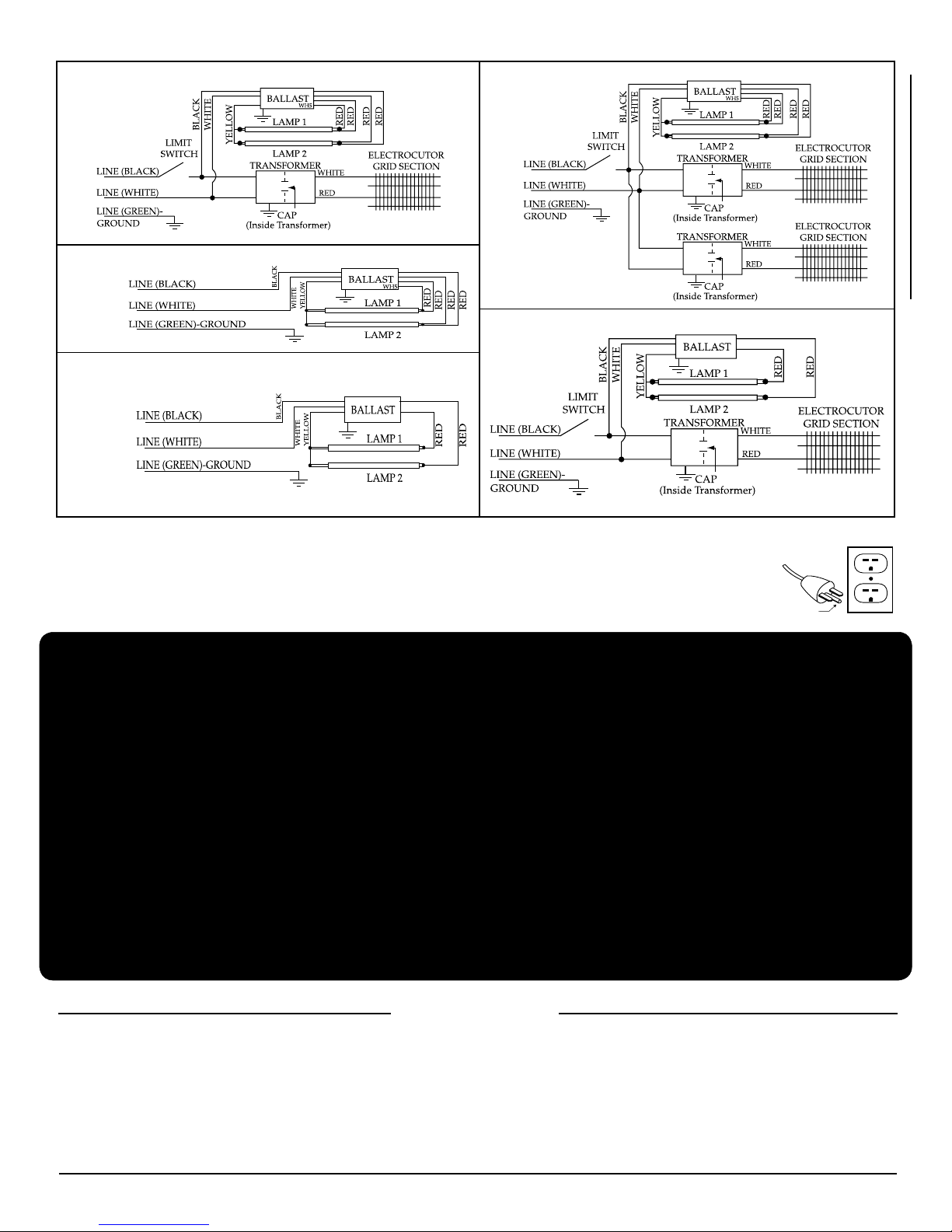
SCHEMATICS--ELECTRICAL CIRCUITS
GROUNDING PIN
GROUNDING RECEPTACLE
230V AC, 50Hz
WH5-230
Models: 711-230, 601T-230, 601E-230, 607-230, 705-230
LINE INPUT
230 VAC
LINE INPUT
230 VAC
Model: 605-230
BLUE
BROWN
Model: 747GT-230
230 VAC, 50Hz
BLUE
BROWN
BLUE
BROWN
Model 220-230
Models 1999GT-230, 219GT-230, 225GT-230,
2000GT-230, 2002GT-230, 601GT-230
All units are equipped with 3-wire grounding plug and to reduce the risk of an electric shock should be plugged
into an appropriate outlet that is properly installed and grounded. Consult a qualied electrician or serviceman if
the grounding instructions are not completely understood, or if doubt as to whether proper grounding exists.
Use only 3-wire extension cords which have 3-prong grounding type plugs and 3-pole receptacles which accept
the product's plug. Replace or repair damaged cords.
LINE INPUT
230 VAC
BLUE
BROWN
WH5-230
Flying Insects are highly attracted to our trap designs and the lamps we have selected. Coupled with good
integrated management procedures, Gilbert® traps provide unequaled ying insect control. And, a few even
provide beauty and style.
Good strategy emphasizes eliminating ies early, well before they get into the area(s) you most need to protect (i.e.
kitchens, production areas, dining areas, etc.). When possible, nd the source of the problem and deal with that rst.
Dumpster control tactics, sanitation, physical exclusion, strategic lighting, employee education, and the judicious use
of approved chemicals are all part of a well integrated y management program (repeat non-stop).
Place the rst traps at entrance(s), then bottlenecks. Spread traps out along the yways from outside entrances (especially those
near dumpsters) to the area(s) you need to protect. Be careful not to position traps too close to an entrance drawing an excess of
insects inside. Window tinting lm will screen out most UV and reduce night-iers congregating on glass doorways.
Light traps are more attractive to (nicky) ies when placed down low. Night iers are more immediately responsive to
traps (you've seen how insanely they are drawn to porch lights). Night iers will go down to traps much more readily
than ies will go up. Most traps should be placed down low, the lower the better. See: gilbertinc.com/strategic.htm.
Consider ADA (American Disabilities Act) when installing traps (See: gilbertinc.com/ada.htm)
1. Empty and clean catch trays (or replace glueboards) frequently. Cultures may result from leaving dead insects in the unit.
Clean bi-weekly or at least as often as local codes require.
2. Disconnect power and wash the lamps and inner-body with
a warm soapy solution and rinse as needed. Clean the grid
section of electrocuters with a stiff brush. All exterior nishes
require cleaning and care to maintain their original luster.
STRATEGIC INSTALLATION
MAINTENANCE
Never clean brass surface with ammonia cleaner to avoid
removing protective lacquer.
3. Replace lamps/glueboards regularly: gilbertinc.com/lam-
prep.htm See also: gilbertinc.com/glueboard.htm
Hg - LAMPS CONTAIN MERCURY
MANAGE IN ACCORD WITH DISPOSAL LAWS
See: www.lamprecycle.org or 1- 800-643-0400
3
4582
4601
4514
6003
4528-S
4530-S
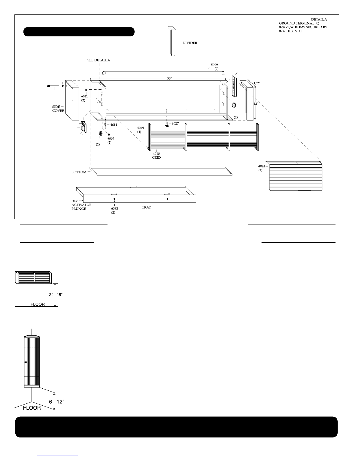
MODEL: Gilbert® 711-230 "Flying Lion"
See Parts List (Page 15) For Part Descriptions
INSTALLATION AND APPLICATION
REMOVE ALL PACKING MATERIALS BEFORE INSTALLATION
PROFESSIONAL ELECTROCUTING LIGHT TRAP
Model 711-230 Flying Lion™
Models 601T-230 Don™, 601E-230 Executive™
INSTALLATION INSTRUCTIONS
1. LAMPS SHOULD BE IN A HORIZONTAL POSITION WHEN UNIT IS
PROPERLY INSTALLED.
2. USING A LEVEL AND PENCIL, DRAW A STRAIGHT 33" LINE APPROX. 3'
ABOVE FLOOR. COME IN 1/4" FROM ONE END AND MARK ACROSS THAT
LINE. MEASURE 32" FROM THAT POINT AND MAKE A SECOND MARK.
MOUNT THE TWO SCREWS (PROVIDED) AT THE CROSSPOINTS, LEAVING 1/2" OF THE SCREW STICKING OUT. SLIDE UNIT ONTO MOUNTING
SCREWS AND CONNECT TO AC POWER.
NOTE: IF MOUNTING ON MASONRY, USE A 3/16" BIT (NOT PROVIDED)
AND DRILL OUT THE TWO CROSS MARKS AND INSERT THE TWO PLASTIC ANCHORS (PROVIDED) BEFORE MOUNTING THE TWO SCREWS.
INSTALLATION INSTRUCTIONS
1. LAMPS SHOULD BE IN A VERTICAL POSITION WHEN UNIT IS PROPERLY INSTALLED.
2. FOR FLAT-WALL MOUNTING: USING A LEVEL AND PENCIL, DRAW
A STRAIGHT 7" LINE APPROX. 5' ABOVE FLOOR. COME IN 1/4" FROM
ONE END AND MARK ACROSS THAT LINE. MEASURE 5 1/4" FROM
THAT POINT AND MAKE A SECOND MARK. MOUNT THE TWO SCREWS
(PROVIDED) AT THE CROSSPOINTS, LEAVING 1/2" OF THE SCREW
STICKING OUT. SLIDE UNIT ONTO MOUNTING SCREWS AND CONNECT
TO AC POWER.
3. FOR CORNER MOUNTING: USING A LEVEL AND PENCIL, DRAW A
STRAIGHT 8 1/2" LINE FROM THE CORNER IN BOTH DIRECTIONS, APPROX. 5' ABOVE FLOOR. MAKE A CROSS MARK AT THE END OF BOTH
LINES. MOUNT THE TWO SCREWS (PROVIDED) AT THE CROSSPOINTS,
LEAVING 1/2" OF THE SCREW STICKING OUT. SLIDE UNIT ONTO MOUNTING SCREWS AND CONNECT TO AC POWER.
4. AFTER MOUNTING UNIT, OPEN THE GUARD AND PUT THE 2 ADDITIONAL SCREWS (PROVIDED) IN THE 2 SLOTS AT THE BOTTOM.
5. MODELS 601E & 601C (ONLY) MAY BE RECESS MOUNTED IN WALL.
NOTE: IF MOUNTING ON MASONRY, USE A 3/16" BIT (NOT PROVIDED)
AND DRILL OUT THE TWO CROSS MARKS AND INSERT THE TWO PLASTIC ANCHORS (PROVIDED) BEFORE MOUNTING THE TWO SCREWS.
Traps may be place higher than recommended, however,
the lower any light trap is placed almost always makes it more effective against ies!
See also: gilbertinc.com.strategic.htm
The Flying Lion™ is a superior trap to control ies
and other ying insects. Keyhole slots are located
on back for wall installation. Generally speaking,
the lower any trap is placed, the more effective
it is against ies. The Flying Lion™ is normally
mounted 24" above the oor.
The Don™, Executive™, Custom™ and Junior™
are for use indoors to control ies and other ying
insects. These models have keyhole slots located
on the back for wall or corner installation and should
be mounted 6" to 12" above oor for best results.
To recess mount the Executive™ or Custom™,
remove wing nut at bottom of inner body (which
contains all electrical components), pull out bottom
of inner body, slide down and out. Mount outer case
permanently into wall. Reverse process to insert
inner body.
4
4514
4582
4601
6003
4526 (2)
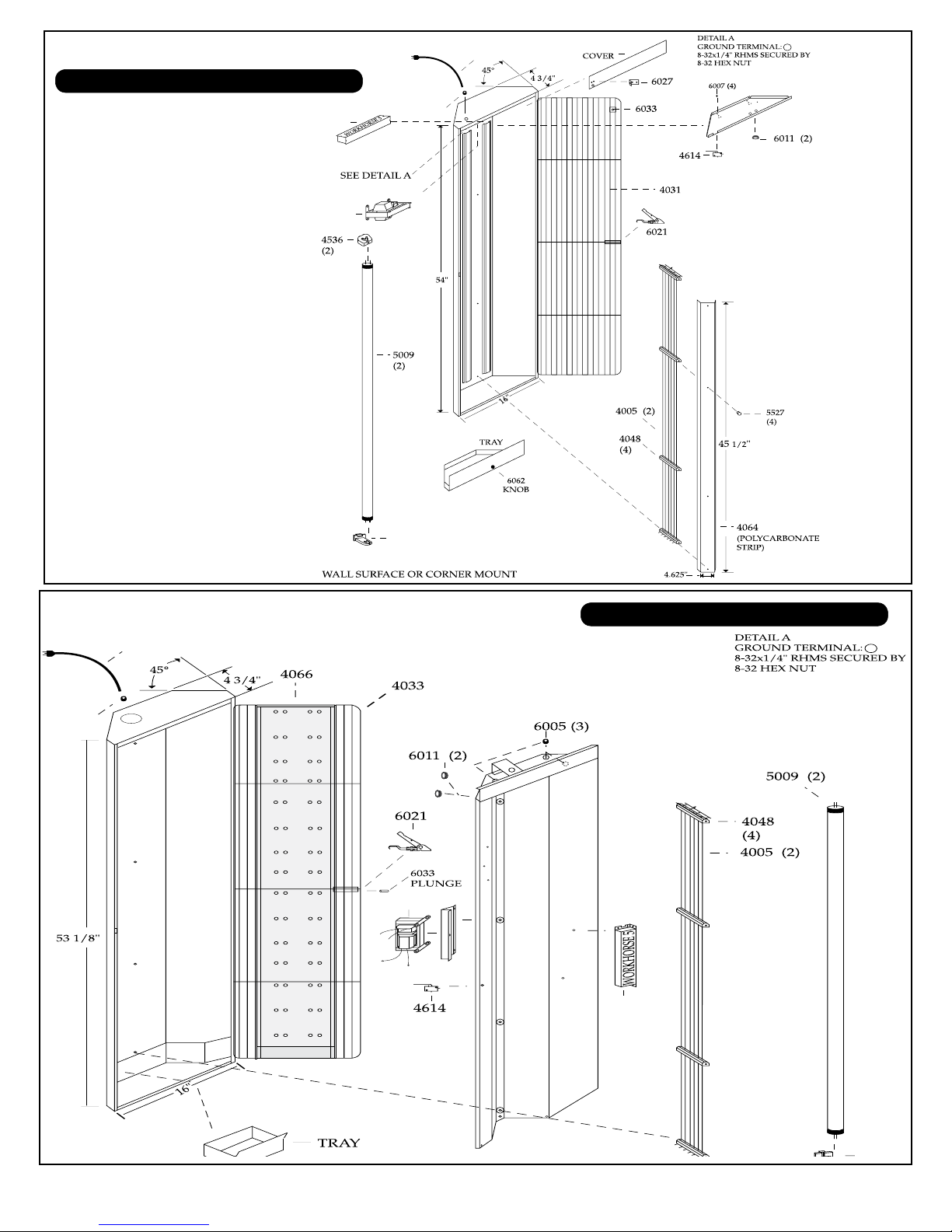
MODEL: Gilbert® 601T-230 "Don"
4514
4601
4582
6003
See Parts List (Page 15) For Part Descriptions
MODEL: Gilbert® 601E-230 "Executive"
See Parts List (Page 15) For Part Descriptions
5
 Loading...