


MDE-5361A
October 2020
FlexPay™ IV CRIND® (with Omnia) Retrofit Kit
Installation Instructions for The Advantage
®
Series

This page is intentionally left blank

Table of Contents
SECTION 1 - INTRODUCTION
PAGES 1-2
S E C T I O N 2 - I M P O R T A N T S A F E T Y I N F O R M AT I O N
PAGES 3-4
S E C T I O N 3 - R E M O V I N G C O M P O N E N T S
PAGES 5-10
S E C T I O N 4 - I N S T A L L A T I O N
PAGES 11-22
S E C T I O N 5 - R E F E R E N C E I N F O R M A T I O N
PAGES 23-24
Purpose . . . . . . . . . . . . . . . . . . . . . . . . . . . . . . . . . . . . . . . . . . . . . . . . . . . . . . . . . . . . . . . . . . . . . . . . 1
Intended Users . . . . . . . . . . . . . . . . . . . . . . . . . . . . . . . . . . . . . . . . . . . . . . . . . . . . . . . . . . . . . . . . . . . 1
Required Tools . . . . . . . . . . . . . . . . . . . . . . . . . . . . . . . . . . . . . . . . . . . . . . . . . . . . . . . . . . . . . . . . . . . 1
Configured Kits - Parts List . . . . . . . . . . . . . . . . . . . . . . . . . . . . . . . . . . . . . . . . . . . . . . . . . . . . . . . . . . 1
Configured Kit Optional Components . . . . . . . . . . . . . . . . . . . . . . . . . . . . . . . . . . . . . . . . . . . . . . . . . 2
Components. . . . . . . . . . . . . . . . . . . . . . . . . . . . . . . . . . . . . . . . . . . . . . . . . . . . . . . . . . . . . . . . . . . 2
Important Safety Information . . . . . . . . . . . . . . . . . . . . . . . . . . . . . . . . . . . . . . . . . . . . . . . . . . . . . . . . 3
i
Before You Begin . . . . . . . . . . . . . . . . . . . . . . . . . . . . . . . . . . . . . . . . . . . . . . . . . . . . . . . . . . . . . . . . 5
Left Option Door . . . . . . . . . . . . . . . . . . . . . . . . . . . . . . . . . . . . . . . . . . . . . . . . . . . . . . . . . . . . . . . . . . 6
CRIND Electronics . . . . . . . . . . . . . . . . . . . . . . . . . . . . . . . . . . . . . . . . . . . . . . . . . . . . . . . . . . . . . . . . 7
Printer . . . . . . . . . . . . . . . . . . . . . . . . . . . . . . . . . . . . . . . . . . . . . . . . . . . . . . . . . . . . . . . . . . . . . . . . . . 8
AFP/HIP 2/DCM2/DCM2.x . . . . . . . . . . . . . . . . . . . . . . . . . . . . . . . . . . . . . . . . . . . . . . . . . . . . . . . . . . 9
FlexPay IV CRIND Retrofit Kit . . . . . . . . . . . . . . . . . . . . . . . . . . . . . . . . . . . . . . . . . . . . . . . . . . . . . . 11
Left Option Door . . . . . . . . . . . . . . . . . . . . . . . . . . . . . . . . . . . . . . . . . . . . . . . . . . . . . . . . . . . . . . . 11
Omnia Assembly . . . . . . . . . . . . . . . . . . . . . . . . . . . . . . . . . . . . . . . . . . . . . . . . . . . . . . . . . . . . . . . 12
Connecting Cables . . . . . . . . . . . . . . . . . . . . . . . . . . . . . . . . . . . . . . . . . . . . . . . . . . . . . . . . . . . . . 13
AC Power . . . . . . . . . . . . . . . . . . . . . . . . . . . . . . . . . . . . . . . . . . . . . . . . . . . . . . . . . . . . . . . . . . . . . . 19
The Advantage Series Units Built Prior to 1999 . . . . . . . . . . . . . . . . . . . . . . . . . . . . . . . . . . . . . . . 19
AC Power Distribution Cable . . . . . . . . . . . . . . . . . . . . . . . . . . . . . . . . . . . . . . . . . . . . . . . . . . . . . . 19
The Advantage Series Units Built After 1999 . . . . . . . . . . . . . . . . . . . . . . . . . . . . . . . . . . . . . . . . . 19
Completing Installation . . . . . . . . . . . . . . . . . . . . . . . . . . . . . . . . . . . . . . . . . . . . . . . . . . . . . . . . . . . . 22
Registering Kits with Gilbarco Warranty . . . . . . . . . . . . . . . . . . . . . . . . . . . . . . . . . . . . . . . . . . . . . . . 22
Related Documents . . . . . . . . . . . . . . . . . . . . . . . . . . . . . . . . . . . . . . . . . . . . . . . . . . . . . . . . . . . . . . 23
Abbreviations and Acronyms . . . . . . . . . . . . . . . . . . . . . . . . . . . . . . . . . . . . . . . . . . . . . . . . . . . . . . . 23
MDE-5361A

S E C T I O N 6 - A P P E N D I X
PAGES 25-40
ii
Appendix A: PCB, Connections, and LED Information . . . . . . . . . . . . . . . . . . . . . . . . . . . . . . . . . . . 25
Omnia PIP Connections . . . . . . . . . . . . . . . . . . . . . . . . . . . . . . . . . . . . . . . . . . . . . . . . . . . . . . . . . 25
Omnia Assembly Jumper . . . . . . . . . . . . . . . . . . . . . . . . . . . . . . . . . . . . . . . . . . . . . . . . . . . . . . . . 26
Omnia PIP LEDs . . . . . . . . . . . . . . . . . . . . . . . . . . . . . . . . . . . . . . . . . . . . . . . . . . . . . . . . . . . . . . 26
Omnia LEDs . . . . . . . . . . . . . . . . . . . . . . . . . . . . . . . . . . . . . . . . . . . . . . . . . . . . . . . . . . . . . . . . . . 27
UPM Board Connections . . . . . . . . . . . . . . . . . . . . . . . . . . . . . . . . . . . . . . . . . . . . . . . . . . . . . . . . 28
Appendix B: System Block Diagram . . . . . . . . . . . . . . . . . . . . . . . . . . . . . . . . . . . . . . . . . . . . . . . . . 30
Appendix C: Verifying Cable Connections . . . . . . . . . . . . . . . . . . . . . . . . . . . . . . . . . . . . . . . . . . . . . 31
Cable Connections on Display Assembly . . . . . . . . . . . . . . . . . . . . . . . . . . . . . . . . . . . . . . . . . . . 31
Appendix D: DCM3 Assembly (M15724A001) . . . . . . . . . . . . . . . . . . . . . . . . . . . . . . . . . . . . . . . . . . 34
FCC Compliance Statement. . . . . . . . . . . . . . . . . . . . . . . . . . . . . . . . . . . . . . . . . . . . . . . . . . . . . . . . 39
FCC Supplier’s Declaration of Conformity . . . . . . . . . . . . . . . . . . . . . . . . . . . . . . . . . . . . . . . . . . . . . 39
MDE-5361A

1
SECTION 1 - INTRODUCTION
1
Purpose
This manual provides instructions to install a 5.7-inch Color Screen FlexPay™ IV CRIND® (with Omnia)
Retrofit Kit into The Advantage® Series. The Advantage Series includes configurations with or without
CRIND. The FlexPay IV CRIND provides a secure payment platform that is EMV®-certified and Payment Card
Industry PIN Entry Device (PCI-PED)-certified.
This manual also includes instructions for installing the Omnia board, which replaces the Dispenser
Communication Module (DCM)2.X [including Gilbarco Systems on Module (GSoM) Printed Circuit Board
(PCBs)] in the FlexPay IV units.
Intended Users
This manual is intended for Gilbarco®-trained and certified Authorized Service Contractors (ASCs).
Required Tools
• Phillips® and Flat-blade Screwdrivers
• 1/4-inch Socket Set (Nut Driver)
• 7- and 8-mm Socket (Nut Driver or Socket Set)
• Diagonal Cutters
• Needle Nose Pliers
• T15 or T20 Torx Driver, depending on the Universal Payment Module (UPM)
• Universal Joint Socket Adapter
• Putty Knife or Scraping Tool (if required)
Configured Kits - Parts List
FlexPay IV CRIND Retrofit Kits are configured based on the serial number of the pump/dispenser unit for
which they are intended. Therefore, the parts list will vary for each configured kit and unit/option type.
For additional part details, refer to the Bill of Materials (BOM) in the kit, contact your distributor, or contact
Gilbarco Customer Service.
A common FlexPay IV CRIND (with Omnia) Retrofit Kit will include the following parts:
• CIM™ insert with UPM assembly (keypad), UX300, display card reader, Omnia Peripheral Interface PCB
(PIP) Assembly
• T-rail assembly with Omnia assembly
• Universal Serial Bus (USB) Printer assembly
• Applause™ Media System, Omnia assembly
MDE-5361A

2
SECTION 1 - INTRODUCTION
1
Configured Kit Optional Components
The following parts are potential configured kit optional components:
• UX400 Contactless Card Reader
• Cabinet Heater (optional for 5.7-inch display)
For a complete parts list of the configured kit, refer to the build ticket that is provided with the kit.
Note: Printers will be needed for all units.
Components
For a complete parts list, see the packing list. The following parts are critical components for
FlexPay IV with Omnia:
Location Description Part # Notes
Located on Left Door Assembly, Advantage Door M14500 Variants are color
5.7” Softkeys M01254A003
5.7” Color Display M10369B001
PCA, Omnia PIP M15649A001
®
Card Reader, VeriFone
Contactless Card Reader, VeriFone,
UX400
Printer Assembly M12479A001 Print head: M13832A001
Cable, Wire and Speaker M09259A001
Located on CRIND Tray Assembly, UPM M13888AXXX “XXX” varies based on
Omnia Assembly Omnia M16181A002
DCM3 M15724A001
Phoenix Supply M04161B001
Fuse Board M05748A001
UX300 M14330A001
M10369B003
M14331A001
Ampire
AM320240SNTN-QW16H
customer r
equirement
MDE-5361A
SECTION 2 - IMPORTANT SAFETY INFORMATION
2
Important Safety Information
The EMERGENCY STOP, ALL STOP, and PUMP
STOP buttons at the cashier’s station WILL NOT
shut off electrical power to the
pump/dispenser. This means that even if you activate
these stops, fuel may continue to flow uncontrolled.
You must use the TOTAL ELECTRICAL
SHUT-OFF in the case of an emergency and not the
console’s ALL STOP and PUMP STOP or similar
keys.
!
WARNING
!
Gilbarco Veeder-Root encourages the recycling of
our products. Some products contain electronics,
batteries, or other materials that may require special
management practices depending on your location.
Please refer to your local, state, or country
regulations for these requirements.
3
Notes: 1) Save this Important Safety Information section in a
readily accessible location.
2) Although DEF is non-flam
Therefore, for DEF cabinets that are atta ch e d to
Diesel dispensers, follow all the notes in this section
that pertain to flammable fuels.
This section introduces the hazards and safety precautions
ssociated with installing, inspecting, maintaining or servicing this
a
product. Before performing any task on this product, read this safety
information and the applicable sections in this manual, where
additional hazards and safety precautions for your task will be found.
Fire, explosion, electrical shock or pressure release could occur and
cause death or serious injury, if these safe service procedures are
not followed.
Preliminary Precautions
You are working in a potentially dangerous environment of
f
lammable fuels, vapors, and high voltage or pressures. Only trained
or authorized individuals knowledgeable in the related procedures
should install, inspect, maintain or service this equipment.
Emergency Total Electrical Shut-Off
The first and most important information you must know is how to
st
op all fuel flow to the pump/dispenser and island. Locate the swi tc h
or circuit breakers that shut off all power to all fueling equipment,
dispensing devices, and Submerged Turbine Pumps (STPs).
mable, Diesel is flammable.
Total Electrical Shut-Off Before Access
Any procedure that requires access to electrical components or th
electronics of the dispenser requires total electrical shut off of that
unit. Understand the function and location of this switch or circuit
breaker before inspecting, installing, maintaining, or servicing
Gilbarco equipment.
Evacuating, Barricading and Shutting Off
Any procedure that requires access to the pump/dispenser or STPs
req
uires the following actions:
• An evacuation of all unauthorized persons and vehicles from the
work area
• Use of safety tape, cones or barricades at the affected unit(s)
• A total electrical shut-off of the affected unit(s)
MDE-5361A
Read the Manual
Read, understand and follow this manual and any other labels or
re
lated materials supplied with this equipment. If you do not
understand a procedure, call a the Gilbarco Technical Assistance
Center (TAC) at 1-800-743-7501. It is imperative to your safety and
the safety of others to understand the procedures before beginning
work.
Follow the Regulations
Applicable information is available in National Fire Protection
Asso
ciation (NFPA) 30A; Code for Motor Fuel Dispensing Facilities
and Repair Garages, NFPA 70; National Electrical Code (NEC),
Occupational Safety and Health Administration (OSHA) regulations
and federal, state, and local codes. All these regulations must be
followed. Failure to install, inspect, maintain or service this
equipment in accordance with these codes, regulations and
standards may lead to legal citations with penalties or affect the safe
use and operation of the equipment.
Replacement Parts
Use only genuine Gilbarco replacement parts and retrofit kits on
pump/dispenser. Using parts other than genuine Gilbarco
replacement parts could create a safety hazard and violate local
regulations.
Federal Communications Commission (FCC) Warning
This equipment has been tested and found to comply with the
limits for a Class A digital device pursuant to Part 15 of the FCC
Rules. These limits are designed to provide reasonable protection
against harmful interference when the equipment is operated in a
commercial environment. This equipment generates, uses, and
can radiate radio frequency energy, and if not installed and used
in accordance with the instruction manual, may cause harmful
interference to radio communications. Operation of this equipment
in a residential area is likely to cause harmful interference in
case the user will be required to correct the interference at his
expense. Changes or modifications not expressly approved by the
manufacturer could void the user’s authority to operate this
equipment.
e
Safety Symbols and Warning Words
This section provides important information about warning symbols
and boxes.
Alert Symbol
This safety alert symbol is used in this manual and on
warning labels to alert you to a precaution which must be
f
ollowed to prevent potential personal safety hazards. Obey
safety directives that follow this symbol to avoid possible
injury or death.
Signal Words
These signal words used in this manual and on warning labels tell
you the seriousness of particular safety hazards. The precautions
below must be followed to prevent death, injury or damage to the
equipment:
DANGER: Al
!
will result in death or serious injury.
WARNING:
could result in death or serious injury.
!
CAUTION
practice which may result in minor injury.
!
CAUTION
unsafe practice which may result in property or equipment
damage.
erts you to a hazard or unsafe practice which
Alerts you to a hazard or unsafe practice that
with Alert symbol: Designates a hazard or unsafe
without Alert symbol: Designates a hazard or
your
which
own
4
SECTION 2 - IMPORTANT SAFETY INFORMATION
2
The pump/dispenser contains a chemical known to the State
of California to cause cancer.
WARNING
!
The pump/dispenser contains a chemical known to the State
of California to cause birth defects or other reproductive
harm.
WARNING
!
Gasoline/DEF ingested may cause unconsciousness
and burns to internal organs. Do not induce vomiting.
Keep airway open.
Oxygen may be needed at scene. Seek medical
advice immediately.
DEF generates ammonia gas at higher temperatures. When
opening enclosed panels, allow the unit to air out to avoid
breathing vapors.
If respiratory difficulties develop, move victim away from source
of exposure and into fresh air. If symptoms persist, seek medical
attention.
WARNING
!
WARNING
!
Gasoline inhaled may cause unconsciousness and
burns to lips, mouth and lungs.
Keep airway open.
Seek medical advice immediately.
WARNING
!
Gasoline/DEF spilled in eyes may cause burns to eye
tissue.
Irrigate eyes with water for approximately
15 minutes.
Seek medical advice immediately.
WARNING
!
Gasoline/DEF spilled on skin may cause burns.
Wash area thoroughly with clear water.
Seek medical advice immediately.
WARNING
!
DEF is mildly corrosive. Avoid contact with eyes, skin, and
clothing. Ensure that eyewash stations and safety showers are
close to the work location. Seek medical advice/recommended
treatment if DEF spills into eyes.
WARNING
!
Working With Fuels and Electrical Energy
Prevent Explosions and Fires
Fuels and their vapors will explode or burn, if ignited. Spilled
leaking fuels cause vapors. Even filling customer tanks will cause
potentially dangerous vapors in the vicinity of the dispenser or
island.
DEF is non-flammable. Therefore, explosion and fire safety
gs do not apply to DEF fluid lines.
warnin
No Open Fire
Open flames from matches, lighters, welding torches or
other sources can ignite fuels and their vapors.
No Sparks - No Smoking
Sparks from starting vehicles, starting or using power tools,
burning cigarettes, cigars or pipes can also ignite fuels and the
vapors. Static electricity, including an electrostatic charge on your
body, can cause a spark sufficient to ignite fuel vapors. Every time
you get out of a vehicle, touch the metal of your vehicle, to
discharge any electrostatic charge before you approach the
dispenser island.
Working Alone
It is highly recommended that someone who is capable of rendering
fi
rst aid be present during servicing. Familiarize yourself with
Cardiopulmonary Resuscitation (CPR) methods, if you work with or
around high voltages. This information is available from the
American Red Cross. Always advise the station personnel about
where you will be working, and caution them not to activate power
while you are working on the equipment. Use the OSHA Lockout/
Tagout procedures. If you are not familiar with this requirement,
refer to this information in the service manual and OSHA
documentation.
or
ir
In an Emergency
Inform Emergency Personnel
Compile the following information and inform emergency
personnel:
• Location of accident (for example, addr
building, and so on)
• Nature of accident (for example, possible heart attack, run
by car, burns, and so on)
• Age of victim(for example, ba
• Whether or not victim has rec
by, teenager, middle-age, elderly)
eived first aid (for example,
stopped bleeding by pressure, and so on)
• Whether or not a victim has vomited (for example, if swallow
or inhaled something, and so on).
ess, front/back of
over
ed
Working With Electricity Safely
Ensure that you use safe and established practices in working with
electrical devices. Poorly wired devices may cause a fire, explosion
or electrical shock. Ensure that grounding connections are properly
made. Take care that sealing devices and compounds are in place.
Ensure that you do not pinch wires when replacing covers. Follow
OSHA Lockout/Tagout requirements. Station employees and service
contractors need to understand and comply with this program
completely to ensure safe
Hazardous Materials
Some materials present inside electronic enclosures may present a
health hazard if not handled correctly. Ensure that you clean hands
after handling equipment. Do not place any equipment in the mouth.
MDE-5361A
ty while the equipment is down.
IMPORTANT: Oxygen may be needed at scene if gasoline has been
ingested or inhaled. Seek medical advice immediately.
Lockout/Tagout
Lockout/Tagout covers servicing and maintenance of machines and
eq
uipment in which the unexpected energization or start-up of the
machine(s) or equipment or release of stored energy could cause
injury to employees or personnel. Lockout/Tagout applies to all
mechanical, hydraulic, chemical, or other energy, but does not cover
electrical hazards. Subpart S of 29 CFR Part 1910 - Electrical
Hazards, 29 CFR Part 1910.333 contains
provision for electrical hazards.
specific Lockout/Tagout
5
SECTION 3 - REMOVING COMPONENTS
3
Ensure that the unit is functional. Check with the manager for any existing
operational issues. If the unit has any special features, such as TRIND
®
,
barcode scanner, and so on, verify proper operation before removal. Print a
system health report to verify printer and CRIND functions.
IMPORTANT INFORMATION
CAUTION
A properly grounded Electrostatic Discharge (ESD) wrist strap must be worn
while servicing any electronic devices or components. Failure to use
electrostatic precautions may damage electronic components and void
warranty.
Before You Begin
To prepare the site and unit for the installation:
1 Perform an inventory of the parts list provided. Ensure that there is no damage to the parts and that all
the parts are accounted for based on the BOM shipped with the kit. Ensure that you carry the
recommended spare parts to the installation site.
Note: Retain all parts (including cables, nuts, bolts, screws, and so on) that are removed. These are
required in case the unit must be reverted to the original as a fallback mitigation.
2 Read all the safety information found in “Important Safety Information” on page 3. Perform a Job
Safety Analysis (JSA) before beginning the installation.
3 Inform the manager.
4 Barricade the unit to be worked on.
5 Check the current state of the unit.
a Verify that the printer firmware is version 3.00 or later by removing and refeeding paper to the
printer while it is still powered.
Note: If the software is not V3.00 or later, be prepared to update the printer software.
b Verify site and dispenser operation.
c Perform a fueling transaction, including printing a receipt.
d Check Applause for idle and busy media (if applicable). Verify video and audio.
e Verify all unit options are functional (for example, intercom).
f Check the pump software version and update to the latest version, if necessary.
MDE-5361A
6
SECTION 3 - REMOVING COMPONENTS
3
Failure to turn off the power to the unit during kit installation may cause injury or bodily
harm from electrical shock. Ensure that all power to the unit is turned off before
opening the door to the unit and during installation.
WARNING
6 Remove power to the unit at the breaker panel. Follow OSHA lockout/tagout procedures.
7 Isolate the two-wire, any Ethernet®
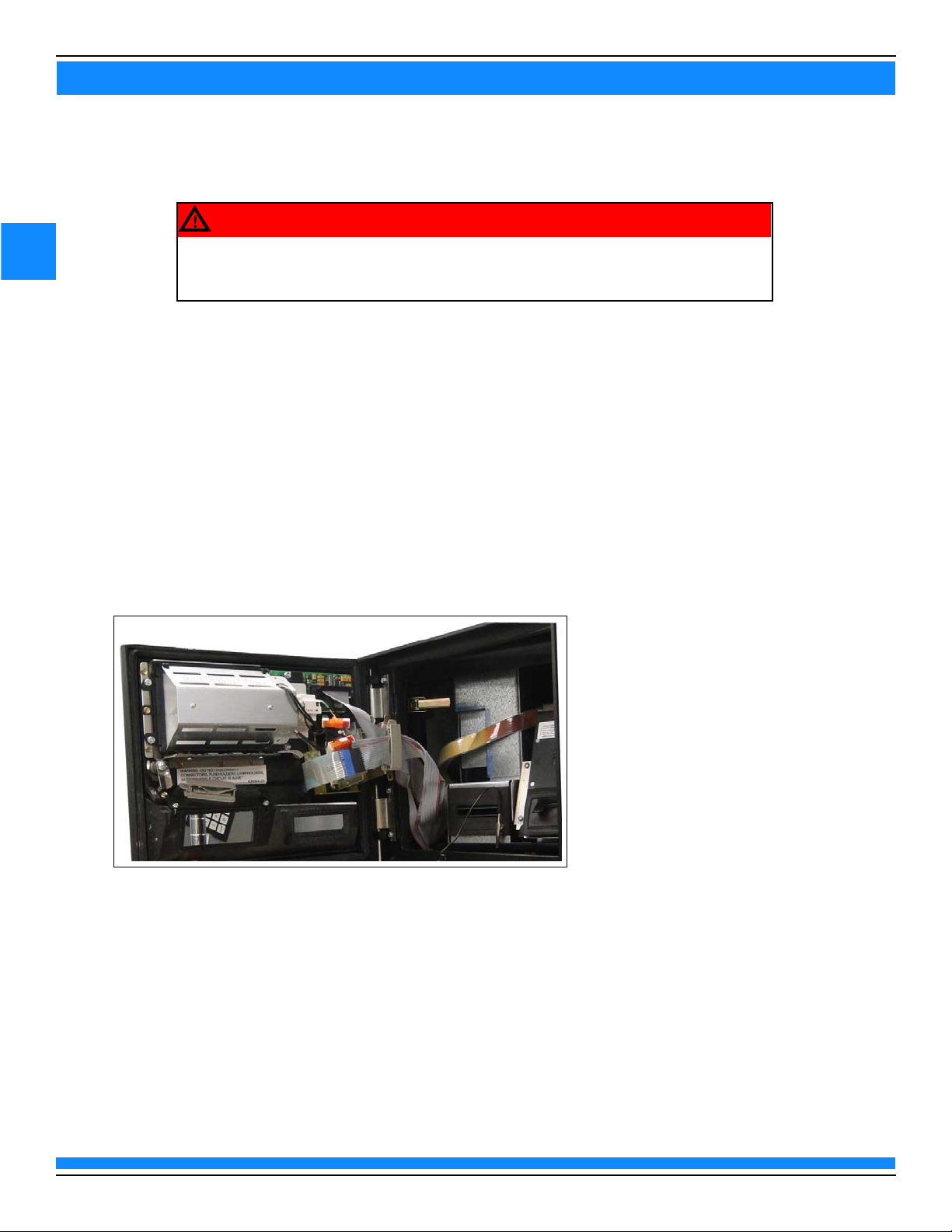
Left Option Door
To remove the left option door:
1 Open the main door by loosening the lower screws that secure the lower portion of the main door and
then open the left and right option doors. Release the four main door latches.
2 Disconnect all the cables from the left option door, CRIND display, card reader, and Contactless Smart
Card (CSC) antenna (if applicable).
Note: Discard the CSC antenna cables as they cannot be reused.
Figure 1: Opening Left Option Door
cabling, and any network connections from the unit.
3
Remove the left option door by pulling the hinge pin up through the hole.
Note: The left option and the main door must be open to gain access to the hinge pin.
4 Remove any existing old gaskets on the option door opening using a putty knife or scraping tool.
5 Remove any customer supplied locks and add to the new option door.
MDE-5361A
7
SECTION 3 - REMOVING COMPONENTS
3
(ii)
(i)
CRIND Electronics
Note: If the unit is not equipped with CRIND, proceed to the installation instructions beginning with
“FlexPay IV CRIND Retrofit Kit” on page 11.
To remove the existing CRIND electronics from the cabinet:
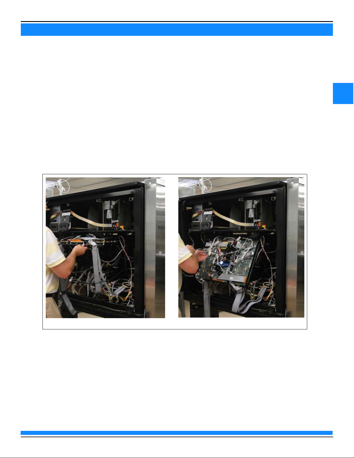
1 Disconnect all the cables connected to the CRIND tray.
2 Disconnect the cables that are connected to the printer. Then remove all the CRIND cables and place
with the CRIND tray, when removed.
3 Remove the CRIND tray by pulling it out toward you and lifting it out of the support bracket
(see Figure 2 (i) and (ii)).
Figure 2: Removing CRIND Tray
MDE-5361A
8
SECTION 3 - REMOVING COMPONENTS
3
Tray Support
Slide Rail
(i)
(ii)
Printer Front View
Printer Rear View
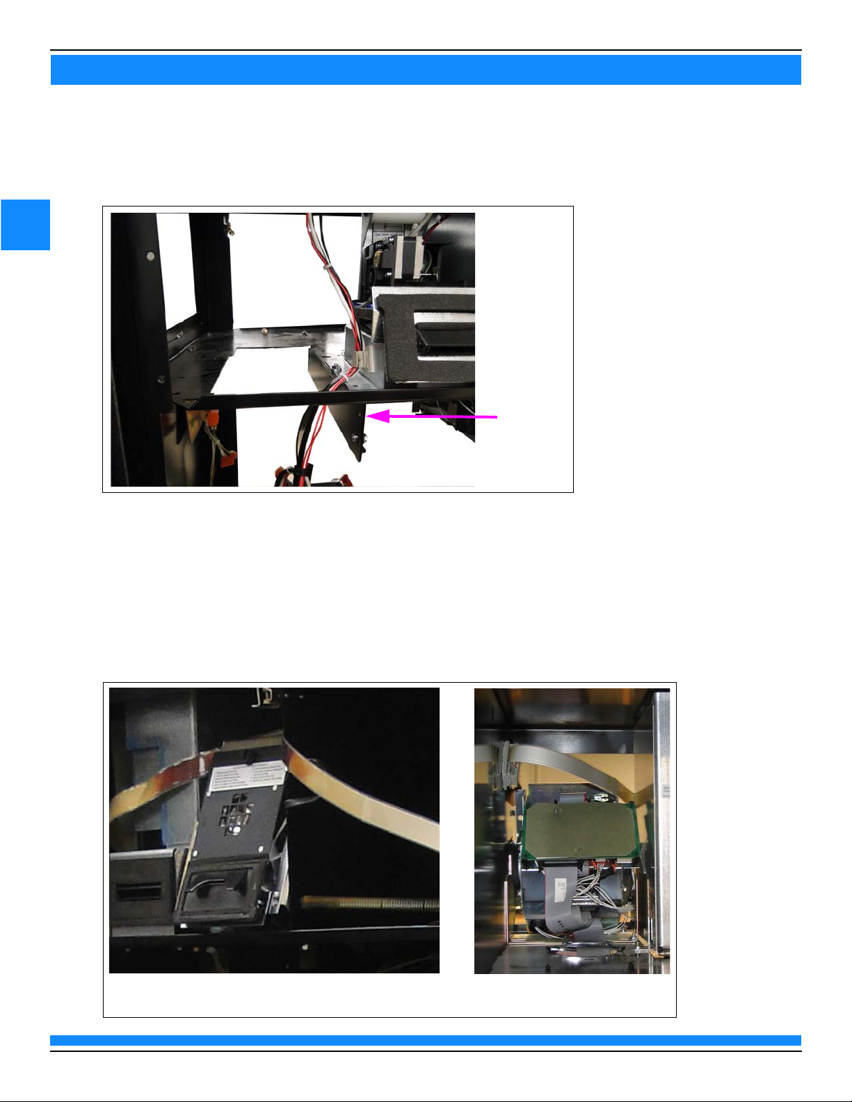
4 Remove the tray and carefully place it in a safe location.
5 Remove the tray support slide rails.
Figure 3: Removing Tray Support Slide Rails
Printer
To remove the printer, disconnect all printer cables and remove the existing printer(s) by removing the three
or four nuts underneath.
Note: The printer cables can be discarded.
Figure 4: The Advantage Series Printer
MDE-5361A
9
SECTION 3 - REMOVING COMPONENTS
3
AFP/HIP 2/DCM2/DCM2.x
To remove the Hub Interface PCB (HIP) 2/AFP/DCM2/DCM2.x bracket:
1 Disconnect all the cables from the AFP, HIP 2, or DCM2/DCM2.x (see Figure 5).
Figure 5: Disconnecting Cables (DCM2)
MDE-5361A
10
SECTION 3 - REMOVING COMPONENTS
3
(i)
(ii)
M4 Nuts
2 Remove the two M00414B005 M4 Nuts to detach the AFP, HIP 2, or DCM2/DCM2.x bracket.
Figure 6: Mounting Bracket
MDE-5361A

11
SECTION 4 - INSTALLATION
4
(i)
(ii)
Rear View of Left Option Door
Front View of Left Option Door
New Left Option
Door Installed
FlexPay IV CRIND Retrofit Kit
Left Option Door
To install the new left option door:
1 Place the new left option door in the opening.
2 Re-insert the hinge pin to secure the new left option door.
Figure 1: Installing Left Option Door
MDE-5361A

12
SECTION 4 - INSTALLATION
4
(i)
(ii)
Printer Shelf
Adapter Bracket
Omnia Assembly
To install the Omnia assembly, proceed as follows:
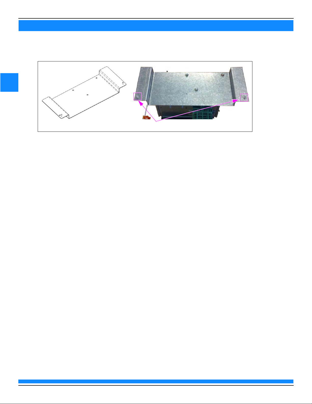
1 Attach the Omnia bracket to Advantage Adapter Bracket (M15122A001) using three M00414B005 M4
Nuts supplied in the kit.
Figure 2: Attaching Omnia Bracket
2 Attach this assembly underneath the Advantage printer shelf, opposite of the main power supply,
using the two holes vacated by the right side CRIND tray rail. Secure with two M00414B005 M4 Nuts.
Figure 3: Mounting Omnia Assembly
3 Continue with instructions to connect cables.
MDE-5361A

13
SECTION 4 - INSTALLATION
4
Omnia PWR Input-J6001
DCM3-J511
AC Input -P104
Side A J301A
Connecting Cables
To connect the cables:
Note: Ensure that the AC cables are not bundled with any non-AC cables.
1 Connect J104 of the M12777A004 Cable to the M04406A001 AC Distribution Cable in the U-channel.
2 Connect P301A/B of the M14340 Cable side A to J301A of the M12777A004 Cable.
3 Connect P301A/B of the M14340 Cable side B to J301B of the M12777A004 Cable.
4 Connect the Ethernet cable to the card reader. The yellow Category 5 (CAT5) cable in the kit matches
the yellow connector on the Omnia PCB (for dedicated side).
Figure 4: Connecting Ethernet Cable to the UX300 Card Reader
Figure 5: M12777A004 Cable Connection
MDE-5361A

14
SECTION 4 - INSTALLATION
4
Display Power
P219 - Audio
Input from
Omnia
P212 - Audio
Output from
Speaker
P214D - USB
P214F - USB
Uplink from
UPM
JP1 - Beeper
Input from
UPM
P213 - Beeper
Input from
UPM
P204 - TRIND
Serial
connection
P214A - USB
P214C - USB
P213 - Video
Input from
UPM
P214B USB to
Printer
JP2 - Side
Select
Jumper
P220 - 24
VDC Input
5 Connect the USB cable from the printer to Omnia PIP, using the port on the left side.
Note: Ensure that the USB printer cable is seated.
Figure 6: Omnia PIP (M15649A001) Connections
MDE-5361A

15
SECTION 4 - INSTALLATION
4
6 Connect P212 to speaker.
Figure 7: Omnia Speaker Connection
Notes: 1) If Applause Media System is installed, there will also be a new audio cable from Omnia PIP and a
video cable from Omnia to UPM. Audio Cable (M14425A002) goes from P419L to Omnia PIP P219.
Video Cable (M14338A00X) goes from Omnia P1 for Side A UPM and Omnia P2 for Side B UPM to
UPM P6.
2) On the Omnia PIP, the J202 connection (RS-232 Serial Cable) will not be used. The cable can be
removed or tucked away neatly on the door.
MDE-5361A

16
SECTION 4 - INSTALLATION
4
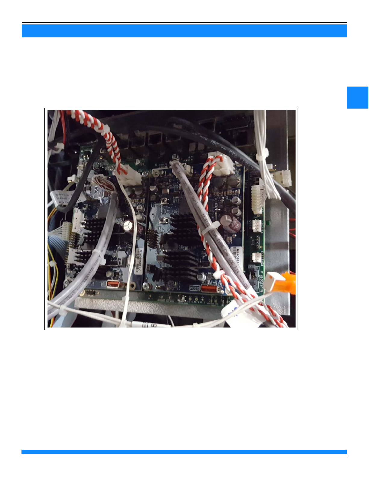
7 Connect all the applicable cables to the Omnia assembly as shown in Figure 8. For additional details
regarding direct CAT5 connections, refer to MDE
Service Manual Insite360™ Forecourt with Applause Media System.
Figure 8: Omnia Board Connections
-5369F FlexPay IV (with Omnia) Programming and
MDE-5361A

17
SECTION 4 - INSTALLATION
4
Figure 9: Connecting Cables
8 Connect the Ethernet cable from each UPM to the Omnia board.
Note: These ports are dedicated. The UPMs and UX300 Card Readers must be connected to the
correct ports.
Figure 4 on page 13 shows the labels on the Omnia board.
Figure 10: Omnia RJ-45 CAT5 connections for UPMs and UX300s (+ Spares)
9 Route the two Braid Terminal Ground Cables [M04431A002 (one from the UX300 and one from the
UPM)] on each Advantage left-side door under the printer tray and secure on the underside with the
cable push mount provided.
MDE-5361A

18
SECTION 4 - INSTALLATION
4
Support Rail
10 Secure the two ring terminals to the support rail using a M00417B101 M5 Screw as shown in
Figure 11.
Figure 11: Securing Ring Terminals
11 Repeat steps 9 on page 17 through 10 for side B of the unit.
Power Supply Grounding Connection
To make grounding connection for the power supply, connect the M04431A002 Cable between the Omnia
assembly and the power supply support rail using a M00417B101 Screw.
MDE-5361A

19
SECTION 4 - INSTALLATION
4
AC Power
The Advantage Series has one of two different AC wiring schemes depending on the year the unit was built.
Refer to the steps below after identifying the configuration present.
The Advantage Series Units Built Prior to 1999
To make AC power connections for The Advantage Series units built prior to 1999:
1 Install the AC Power Adapter Cable (R20580-G3) by inserting it between J601 and P601
(see Figure 12).
2 Plug the AC power input of M04406 from the Omnia assembly into P601 of R20580-G3 Cable.
Figure 12: Plugging AC Power Input from Omnia to R20580-G3
AC Power Distribution Cable
The Advantage Series Units Built
To make AC power connections for The Advantage Series units built after 1999:
1 Locate the AC Adaptor Cable Assembly (T19612-G2) from the pump power supply located across the
bottom of the electronics cavity.
2 Plug M04406 into J550 or an available three-pin connection.
3 Ensure that all AC connections are paired as black-to-black, white-to-white, and green-to-green.
Note: After all the cables have been routed from the doors to the interior of The Advantage Series unit,
ensure to route the cables to avoid pinching.
After 1999
MDE-5361A

20
SECTION 4 - INSTALLATION
4
T19612 Cable Assembly AC Adaptor
J601
J708
J551
J404
J550
Tra nsf or mer A ssy
T19706-Gx
Auxiliary A/C Pickoff
Auxiliary A/C Pickoff
Vap orVa c
Connect To Frame
To A/C Distribution
Cable M04406 (Power
to CRINDS, Omnia
Assy)
Connection from conduit
Use the T19612 Cable Assembly AC Adaptor to connect to the other modules in the dispenser that require
AC voltage. The T19612 Cable Assembly AC Adaptor connects to the J401 connector attached to the
conduit, from where it is connected to the modules in the dispenser wherever AC voltage is required.
(see Figure 13 on page 20).
Figure 13: AC Power Distribution Cable Connection
Figure 14 shows internal connections for T19612-G2 in the dispenser.
Figure 14: T19612-G2 Internal Connections
MDE-5361A

21
SECTION 4 - INSTALLATION
4
To route the cables:
1 Secure the door cables underneath the printer paper holder.
Figure 15: Securing Door Cables Underneath Printer Paper Holder
2 Tie-wrap the cables to the printer shelf, near the main door hinge, keeping both doors completely
open. This will ensure there is sufficient space between the cables.
Figure 16: Securing Cables to Printer Shelf
MDE-5361A

22
SECTION 4 - INSTALLATION
4
For start-up information, refer to MDE-5221 FlexPay IV CRIND Start-up
Manual.
IMPORTANT INFORMATION
Cable routing is critical. It is very important to route and dress the cables
properly. Exercise care in routing the cables, keeping in mind that the door(s)
opens and closes for service. The cables must be dressed neatly. Ensure that
there is no interference after the cables are connected and routed.
ESD ground straps can be bundled together, but need to be separated from
data and power cables.
IMPORTANT INFORMATION
Completing Installation
To complete the installation, inspect all the connections and cable routing before applying power.
For detailed block diagrams of cable connections, refer to “Appendix C: System Block Diagram” on page 31.
Registering Kits with Gilbarco Warranty
To register the kits with Gilbarco Warranty:
1 After the kits are successfully installed, register kits through web commissioning within 30 days.
2 Provide the correct model and serial numbers.
Note: Registering the kits ensures that proper warranty is applied.
The Advantage Retrofit Kit part number is EPK M7 ADV.
MDE-5361A

23
SECTION 5 - REFERENCE INFORMATION
5
Related Documents
Document
No.
MDE-2531 Gilbarco Pump and Dispenser Start-up and Service Manual
MDE-5221 FlexPay IV CRIND Start-up Manual
MDE-5223 FlexPay IV CRIND Service/Troubleshooting Guide
MDE-5227 M7 Maintenance Tool User Guide
MDE-5369 FlexPay IV with Omnia Start-Up and Service Manual
PT-1728 The Advantage Series Pumps and Dispensers Illustrated Parts Manual
PT-1869 Gilbarco Products Recommended Spare Parts for Domestic Products
Title
Abbreviations and Acronyms
Ter m Description
AFP Auxiliary Feature PCB
ASC Authorized Service Contractor
BNA Bank Note Acceptor
BOM Bill of Material
BRCM Back Room Communication Module
CAT5 Category 5
CIM Customer Interface Module
CRIND Card Reader in Dispenser
CSC Contactless Smart Card
D-Box Distribution Box
DCM Dispenser Communication Module
®
EMV Europay
ESD Electrostatic Discharge
GSoM Gilbarco Systems on Module
JSA Job Safety Analysis
MOC Major Oil Company
OSHA Occupational Safety and Health Administration
PCB Printed Circuit Board
PCI Payment Card Industry
PCI-PED Payment Card Industry PIN Entry Device
POS Point of Sale
PIP Peripheral Interface PCB
SSoM Secure System on Module
TRIND Transmitter/Receiver in Dispenser
UPM Universal Payment Module
USB Universal Serial Bus
VDC Voltage Direct Current
W&M Weights and Measures
, MasterCard®, and Visa
®
MDE-5361A

24
SECTION 5 - REFERENCE INFORMATION
5
This page is intentionally left blank.
MDE-5361A

25
SECTION 6 - APPENDICES
6
Appendix A: PCB, Connections, and LED Information
Omnia Board Connections
Connector Port Number Function From To
7-pin MTA P60001 Power IN P60001 Power input
2-pin plug P6901 Audio out to Omnia
A
PIP
2-pin plug P6902 Audio out to Omnia
25-pin high density P1 Video out to UPM A P1 UPM-P6
25-pin high density P2 Video out to UPM B P2 UPM-P6
5-pin MTA P300 Two-wire connection
2-pin MTA P303 Two-wire to pump P303 Pump-P1109
7-pin MTA P304A Backroom
4-pin plug P304B Backroom
PIPB
POS
to
connection/DCM3
connection
P6901 Omnia PIP: P219
P6902 Omnia PIP: P219
P300 Conduit/POS
P304A DCM3-J17
P304B Conduit
Note: Verify P6001 of the Omnia board is on the same side as the Weights and Measures
(W&M) switch.
For more information, refer to “Appendix B: System Block Diagram” on page 30.
Omnia PIP Connections
The following table lists the connections on the Omnia PIP:
Connector Port Number Function From To
10-pin MTA P201 Cash Acceptor P201 BNA
6-pin MTA P204 TRIND P204 TRIND J182
3-pin Plug P213 BEEP Connector P213 UPM P2
4-pin Plug P220 24 VDC IN P220 Power Supply Cable
Mini Universal
Bus (USB)
Serial
USB P214A USB Out P214A USB Expand
USB P214B USB Out P214B USB Expand
USB P214C USB Out P214C USB Expand
USB P214D USB Out P214D USB Expand
4-pin MTA P219 Speaker Input from Omnia P219 P6901A and P6901B
2-pin Mat-n-Lok P211 Audio to Left Speaker P211 Left Speaker
25-pin P205 Video Input from UPM P205 UPM P5
20-pin P206 LVDS Data to 10.4” P206 10.4”
33-pin P207 Video Data to 5.7” P207 5.7”
2-pin P215 Up/Down for 5.7”
10-pin P208 10.4” Backlight P208 10.4” Backlight
3-pin P210 5.7” Backlight P210 5.7” Backlightt
USB UPLINK USB IN USB UPLINK UPM P4
P215 DNP
(M1
4340)
MDE-5361A

26
SECTION 6 - APPENDICES
6
Omnia Assembly Jumpers
The following table lists the status and functions of jumpers:
Jumper Description
Omnia Board
J3 Jumper ON = Battery connected
Jumper OFF = Battery disconnected
Omnia PIP
JP2 Jumper ON = Side B
Jumper OFF = Side A
Omnia PIP LEDs
Reference
Designator Color Function Behavior
D1 Green USB link ON: U8 connected to USB Hub
D4
D5
D6
D7
D9
D11
D12
D14
D20
D21
D22
D23
D24
D25
D26
Red USB over current ON: Over current fault detected on P214D
Ye ll ow Serial
communication
Green Power good ON: 5 VDC power is good
ON: USB device plugged into P214A
OFF: No USB device connected
ON: USB device plugged into P214B
OFF: No USB device connected
ON: USB device plugged into P214C
OFF: No USB device connected
ON: USB device plugged into P214B
OFF: No USB device connected
OFF: Normal operation
ON: Over current fault detected on P214B
OFF: Normal operation
ON: Over current fault detected on P214C
OFF: Normal operation
ON: Over current fault detected on P214A
OFF: Normal operation
ON: UPM TX to BNA
OFF: UPM is not communicating with BNA
ON: BNA TX to UPM
OFF: BNA is not communicating with UPM
ON: UPM TX to TRIND
OFF: UPM is not communicating with TRIND
ON: TRIND TX to UPM
OFF: TRIND is not communicating with UPM
OFF: 5 VDC power fault or board not powered
ON: 3.3 VDC power is good
OFF: 3.3 VDC power fault or board not powered
ON: 24 VDC power is good
OFF: 24 VDC power fault or board not powered
Note: Install a jump jack on JP2 when Omnia PIP is located on Side 2 of the dispenser.
MDE-5361A

27
SECTION 6 - APPENDICES
6
Omnia LEDs
Reference Designator Color Function Behavior
D7 Green 1.5V power good LED ON: 1.5 V power is good
OFF: 1.5 V power is not good
D8 1.1V power good LED ON: 1.1 V power is good
OFF: 1.1 V power is not good
D17 1.8V power good LED ON: 1.8 V power is good
D18 1.35V power good LED ON: 1.35 V power is good
D22 Power Input LED ON: Omnia PCB has 24 VDC from power supply
D23 5V USB power good
LED
D24 5V power good LED ON: 5 V power is good
D25 5VPS power good LED ON: 5 VPS power is good
D26 3.3V power good LED ON: 3.3 V power is good
D37 Yel lo w CRIND 2W RX Blinking: Data received from POS
D38 CRIND 2W TX Blinking: Data sent to POS
D39 Green CRIND TX Enable ON: TX enable line is act
D45 Yel lo w Pump (POS) 2W RX Blinking: Data received from POS
D47 Pump (POS) 2W TX Blinking: Data sent to POS
D49 Green Pump (POS) TX Enable ON: TX enable line is act
D53 Yel lo w Pump 2W RX Blinking: Data received from pump
D56 Pump 2W TX Blinking: Data sent to pump
D57 Green Pump TX Enable ON: TX enable line is act
D58 Green Active Mode LED ON: Omnia configured correctly.
D73 Yel lo w 7.5V power good LED ON: 7.5 V power is good
OFF: 1.8 V power is not good
OFF: 1.35 V power is not good
OFF: Omnia PCB does not have 24 VDC from
ON: USB power is good
OFF: USB power is not good or the regulator is not
OFF: 5 V power is not good
OFF: 5 VPS power is not good
OFF: 3.3 V power is not good
OFF: Omnia will not send messages to the POS
OFF: Omnia will not send messages to the POS
OFF: Omnia will not send messages to the pump
OFF: Omnia not properly configured
OFF: 7.5 V power is not good or is not enabled by
r supply
powe
enabled.
ive. Omnia will
successfully communicate to the POS
ive. Omnia will
successfully communicate to the POS
successfully communicate to the pump
a
Omni
ive. Omnia will
MDE-5361A

28
SECTION 6 - APPENDICES
6
Keypad Connector Tab
Some of the connectors have a tab on the side that must be pressed prior to
removing the connector. You must depress and hold the tab on the side of the UPM
softkey connector if you want to remove it. If you do not press the tab, the wire might
be pulled out from the connector.
CAUTION
Keypad Connector Tab
(used on all systems)
Video Connector Tab (used only with Applause Media System)
UPM Board Connections
Figure 1: Keypad and Video Connector Tabs
MDE-5361A

29
SECTION 6 - APPENDICES
6
The following table lists the connections on the UPM:
Port Number To Function
P1 24 V Power into UPM UPM power (and keypad heater power, if equipped)
P2 Omnia PIP - (P213),
softkeys, door node
(P2111), door switch (192),
ADA, call
P3 Omnia Blue UPM
Omnia Yellow Card Reader
(see Figure 1 on page 28)
P4 Omnia PIP - USB uplink USB uplink to the Omnia PIP
P5 Omnia PIP - P205 Video out
P6 Omnia - P406 Applause
Media System video input
Input/Output (I/O) to multiple CRIND functions:
• Softkeys
•ADA
• Door switch
• Beeper
Ethernet to the Omnia board
Video input from the Omnia
The following table lists the peripherals for the cables:
Part Number Port Number Function
M03184A00X P201 Cash Acceptor
R20773-GX P204 TRIND
M09267A00X P213 BEEP Connector
M09794A00X P220 24 VDC Power In
M14337A001 P1 UPM Heater Cable
MDE-5361A

SECTION 6 - APPENDICES
MDE-5361A
6
30
Figure 2: Cable Block Diagram for FlexPay IV CRIND
Appendix B: System Block Diagram

31
SECTION 6 - APPENDICES
6
Appendix C: Verifying Cable Connections
Cable Connections on Display Assembly
Figure 3 shows the cable connections on the display assembly.
Figure 3: Cable Connections on Display Assembly
To verify the cable connections:
Power Cabling
Ensure that the power cables are connected as follows:
1 Omnia PIP: P220 port is connected to +24 V Cable (M14340A001).
2 UPM: P1 port is connected to +24 V cable.
3 Omnia: P6001 port is connected to +24 V cable.
Omnia PIP Cabling
Ensure that the Omnia PIP board cables are connected as follows:
1 Omnia PIP USB uplink port is connected to the USB Cable (M03695B004) and connected to the P4 port
on the UPM.
2 P213 port of Omnia PIP is connected to the M13119 Cable, which connects to the UPM P2.
3 P211 port is connected to the Speaker Cable (M09259A004) and to the left speaker.
4 P205 port is connected to M14136A00X Cable and to UPM P5.
MDE-5361A

32
SECTION 6 - APPENDICES
6
You must depress and hold the tab on the side of the UPM softkey connector to
remove it. If you do not depress the tab, you are very likely to pull out the wire from
the connector.
CAUTION
5 P206 port is connected to 10.4-inch LVDS Cable (M13722A002) and to 10.4-inch display.
6 P207 port is connected to 5.7-inch Parallel Cable (M9224B001) and to 5.7-inch display.
7 P209 port is connected to 10.4-inch Backlight Cable (M9224B001) and to 10.4-inch display.
8 P210 port is connected to 5.7-inch backlight leads from the 5.7-inch display.
UPM Cabling
Ensure that the UPM cables are connected as follows:
1 P1 port is connected to 24 V Power Cable (M14340A001).
2 P2 port of Softkey Cable (M13119AXXX) is connected to the softkeys, P213 of Omnia PIP for the
beeper, J2111 for the door node, and J192 for the door switch.
3 P3 port of Ethernet Cable (Q13850-XX) is connected to P303A/B on Omnia board.
4 P4 port of USB Cable (M03695B007) is connected to USB UPLINK on Omnia PIP board.
5 P5 port of LVDS Cable (M14136A00X) is connected to P205 on Omnia PIP board.
6 P6 port of LVDS Cable (M14338A001) is connected to P606A/B on UPM board.
7 Earth Ground Cable (M04431A002) is connected to the U-channel running across the bottom of the
unit cavity. These need to be mounted with separate bolts and not together.
MDE-5361A

33
SECTION 6 - APPENDICES
6
UX300/UX301/UX400 Card Reader Cabling
Ensure that the card reader cables are connected as follows:
1 P1 port is connected to 24 V Power Cable (M14340A001).
2 LAN port of Card Reader Cable (M13443B006) is connected to the Omnia.
3 If UX400 contactless reader is present, the RF port (UX400 RF) on the card reader connects to the RF
port (UX400 RF) on the contactless reader.
4 If UX400 contactless reader is present, power/data port (UX400 COMM) on the card reader connects
to the power/data (UX400 COMM) port on the contactless reader.
The card reader has an earth ground cable that is connected to the U-channel.
MDE-5361A

34
SECTION 6 - APPENDICES
6
J15 - 24 VDC
Power In
J16 - 24 VDC
Power Out
(Optional)
J21 - OLC in/
Two-Wire Out
J17 - Ethernet
to Omnia PCB
Appendix D: DCM3 Assembly (M15724A001)
The DCM3 is used when high-speed communication is required across the forecourt. The DCM3 is only used
with the BRCM2. Connect all the applicable cables to the DCM3 assembly as shown in Figure 4.
Figure 4: DCM3 Connections
LEDs
MDE-5361A
Reference Designator Color Function Behavior
D1 Green 1.2 V Power Good ON: 1.2 VDC ON
OFF: 1.2 VDC fault or board
not powered
D9 3.3 V Power Good ON: 3.3 VDC ON
OFF: 3.3 VDC fault or board
not powered
D8 24 V Power Good ON: 24 VDC ON
OFF: 24 VDC fault or board not
powered
D6 Yellow High Speed ACT ON: Link present
Blink: TX/RX data
OFF: No link present
D7 Green High Speed Link ON: Successful connection to
BRCM2
OFF: No link to BRCM2

35
SECTION 6 - APPENDICES
6
*CRIND Two-wire becomes inactive with EMV.
Connection Table (M15724A001)
Connector Port Number Function From To
RJ-45 J17 Ethernet J21 Omnia P304
5-pin MTA J21 OLC/two-wire Conduit/J21 Omnia P300
2-pin MTA J15 Power IN DCM3
2-pin MTA J16 Power Out N/A N/A-no current use
DCM3 Two-Wire Connections
These instructions detail how to perform two-wire connections when a DCM3 is used in the system. The
DCM3 is required when a BRCM2 is used to provide high-speed communication across the forecourt. The
BRCM2 when used with the DCM3 supports the following two modes:
• The option of merging the high speed data onto the same conductors used for current loop.
• The option of not merging high-speed data onto the same conductors used for current loop. This setup
requires additional wire pairs brought out to each dispenser.
DCM3 Two-Wire Connection (Merged)
Ensure that the two-wire connection when high speed data is merged onto the same conductors is as
follows:
1 Connect P21 of the M11961A004 cable to J21 of the DCM3.
2 Connect J300 of the M11961A004 cable to P300 of the Omnia.
3 Connect the Y/Y pair of the M11961A004 to the B/Y pair of wires coming from the conduit.
Figure 5: MOC (Merged), Pre-EMV*
MDE-5361A

36
SECTION 6 - APPENDICES
6
DCM3 Two-Wire Connection (Non-Merged)
Ensure that the two-wire connection when high speed data is not merged onto the same conductors is as
follows:
1 Connect P21 of the M11961A004 cable to J21 of the DCM3.
2 Connect the Y/Y pair of the M11961A004 to the designated wires coming out of the conduit.
3 Connect J300 of the M02993A005 cable to P300 of the Omnia.
4 Connect the B/Y pair of the M02993A005 to the B/Y pair coming from the conduit.
Figure 6: MOC (Non-Merged)
MDE-5361A

37
SECTION 6 - APPENDICES
6
*CRIND Two-wire becomes inactive with EMV.
Generic (Merged)
The Omnia board supports high speed communication via the BRCM2. When connection to a BRCM2 is
required, the kit will ship with a DCM3 (M15724A001) attached to the Omnia bracket assembly. See the
following wiring instructions.
Ensure that the connection to Omnia is as follows:
1 Connect P21 of the M11961A005 cable to J21 of the DCM3.
2 Connect the Y/Y pair of the M11961A005 to the R/Y pair of wires coming from the conduit.
3 Cut J300 off M11961A005.
4 Connect the R/Y pair of M11961A005 to the R/Y pair of M02993A005.
5 Connect J300 of the M02993A005 cable to P300 of the Omnia.
Figure 7: Generic (Merged), Pre-EMV*
MDE-5361A

38
SECTION 6 - APPENDICES
6
Generic (Non-Merged)
Ensure that the connection to Omnia is as follows:
1 Connect P21 of the M11961A005 cable to J21 of the DCM3.
2 Connect the Y/Y pair of the M11961A005 to the designated wires coming the conduit.
3 Connect J300 of the M02993A005 cable to P300 of the Omnia.
4 Connect the B/Y pair of M02993A005 to the B/Y pair of wires coming from the conduit.
5 Connect the R/Y pair of the M02993A005 to the R/Y pair coming from the conduit.
Figure 8: Generic (Non-Merged)
MDE-5361A

39
SECTION 6 - APPENDICES
6
FCC Compliance Statement
This device complies with Part 15 of the FCC Rules. Operation is subject to the following two conditions:
(1) This device may not cause harmful interference, and (2) this device must accept any interference
received, including interferences that may cause undesired operation.
FCC Supplier’s Declaration of Conformity
47 CFR § 2.1077 Compliance Information
Unique Identifier: FlexPay IV CRIND Advantage Retrofit Kit
Responsible Party - U.S. Contact Information
Gilbarco Veeder-Root
7300 West Friendly Avenue
Greensboro, North Carolina, USA
27410-6200
1-336-547-5000
MDE-5361A

40
The Advantage® Series, CRIND®, Gilbarco®, and TRIND® are registered trademarks of Gilbarco Inc. Applause™ Media System, CIM™, E-CIM™, FlexPay™
Passport™ and InSite 360™are trademarks of Gilbarco Inc. EMV® is a registered trademark of EMVCo LLC. Ethernet® is a registered trademark of Xerox
Corporation. Europay® and MasterCard® are registered trademarks of MasterCard International Inc. Phillips® is a registered trademark of Phillips
Screw Company. VeriFone® is a registered trademark of VeriFone Inc. Visa® is a registered trademark of Visa Inc.
© 2020 Gilbarco Inc.
7300 West Friendly Avenue · Post Office Box 22087
Greensboro, North Carolina 27420
Phone (336) 547-5000 · http://www.gilbarco.com · Printed in the U.S.A.
MDE-5361A FlexPay™ IV CRIND® (with Omnia) Retrofit Kit Installation Instructions for The Advantage® Series
 Loading...