


IC Radio Standards Specification: RSS-210
Certification Exhibit
FCC ID: N6SLFADV
IC: 827B-LFADV
FCC Rule Part: 15.209
ACS Report Number: 13-0073
Manufacturer: Gilbarco Inc.
Model: LFADV
Manual
5015 B.U. Bowman Drive Buford, GA 30518 USA Voice: 770-831-8048 Fax: 770-831-8598

The Advantage® Series, MPD® -3, Encore®, and
Eclipse
®
Units
nary
i
TRIND® Start-Up, Service, and
m
i
3
/1
Parts Manual
rel
P
22
3/
0
MDE-3664B

ECR™MultiLine
Tank Monitor
Eclipse®MPD
TRIND
EMC™Optimum™Series
TCR
Encore®Passport
VaporVac
FlexPay™PAM™1000
Titan
G-SITE®Performer
G-CAT™PAM
Ultra-Hi
Gilbarco®The Adv antage®Series
Gilbert
SMART Connect
™
ValueLine
Computer Programs and Documentation
All G ilbarco Inc. and/or Veeder Root Company computer programs (including software o n diskettes and within me mory chips) and documentation are copyrighted by, and shall
remain the property of, Gilbarco Inc. and/or VeederRoot Company.Such computer programs and documents may also contain trade secret information. The duplication, disclosure,
modification, or unauthorized use of computer programs o r documentationis strictly proh ibited, unless otherwise lice ns ed by Gilbarco Inc. and/or Veeder Root Company.
Federal Communications Commission (FCC) Warning
This equipment has bee n tested and found to comply with the limits for a Class A digitaldevice pursuant to Part 15 of the FCC Rules. These limits are designed to provide
reasonable protection against harmf ul inter ference when the eq uipment is operated in a commercial environment. This equipment generate s, uses, and can radiate radio frequency
energy,and if not installed and used in accordance with the instruction manual, may cause harmful interference to radio communications. Operation of this equipment in a residential
area is likely to c
the manufacturer could void the user’s autho rity to operate this e quipm e nt.
ause harmful interference in which case the user will be required to correct the interference at his own expense. Changes or modificat ions not expressly approved by
Industry Canada Warning
This device compl i es with I ndustr y Canada licence-exempt RSS standard(s). Operation i s subject to the following two conditions:
(1) this device may no t cause interference, and
(2) this device must accept any interference, inc lu d ing int e rference that may cause undesired operatio n of the device.
Le présent appareil est conforme aux CNR d'Industrie Canada applicables aux appareils radio exempts de licence. L'exploitation est autorisée aux deu x conditions suivantes :
(1) l'appareil ne doit pas produire de brouillage, et
(2) l'utilisateur de l'appareil doit accepter tout brouillage radioélectrique subi, mê me si le brouillage est susceptible d'en co mpromettre le fon ctionnement.
Under Industry Canada regulations, this radio t ransmitter may only operate using an antenna of a type and maximum (or lesser) gain approved for the transmitter by Industry Canada.
To reduce potential radio interference to other users, the antenna type a nd its ga in should be so chose n that t he equ ivalent isot ro p ically rad iat ed po wer (e.i.r. p.) is not more than that
necessary for successful communication.
Conformément à la réglementation d'Industr ie Ca nada, le présent émetteur radio peut fonctionner avec une antenne d'un type et d'un gain maximal (ou inférieur) approuvé pour
l'émetteur par Industrie Canada. Dans le but de réduire les risques de brouillage radioélectrique à l'intention des autres utilisateurs, il faut cho isir le t ype d'antenne et son gain de sorte
que la pu issance isotrope rayonnée équivalente (p.i.r . e.) ne dépasse pas l'inten s ité néces saire à l'établissement d'une communication satisfaisante.
Approvals
Gilbarcois anISO 9001:2008registeredcompany.
Underwriters Laboratories (UL):
U L File# Products listed withU L
MH1941
MH8467 Transac System 1000 and PAM 1000
E105106 DellDHM Minitower
E165027 G-SITEandPassport Systems
All Gilbarco pumps and dispensers that bear
theUL listing mark.
California Air Resources Board (CARB):
ExecutiveOrder# Product
G-70-52-AM Balance Vapor Recovery
G-70-150-AE VaporVac
National Conference of Weights and Measures (NCWM) - Certificate of Conformance (CoC):
Gilbarco pumps and dispensers areevaluated by NCWM u nder the NationalType Evaluation Pro gram (NTEP). NCWM has issued the following CoC:
CoC# Product Model # CoC# Product Model #
02-019 Encore Nxx 02-036 Legacy Jxxx
02-020 Eclipse Exx G-SITE Printer (Epson) PA0307
02-025
02-029 CRIND — G-SITE Mini Tower PA0301
Meter - C Series PA024NC10 G-SITE Distribution Box PA0306
Meter - C Series PA024TC10 G-SITE Keybo ard PA0304
02-037
TS-1000 Console — G-SITE Monitor PA0303
TS-1000 Controller PA0241 G-SITE Printer (Citizen) PA0308
02-030 Distribution Box PA0242 02-038 C+ Meter T19976
Meter - EC Series PA024EC10 02-039 Passport PA0324
VaporVac Kits CV 02-040 Ecometer T20453
05-001 Titan KXXY Series
Trademarks
Non-registered
Applause™Media Sys tem G-SITE®Lite™SMART Meter
™
CIM
™
C-PAM
™
G-SITE®Link
trademarks
™
™
Highline
™
Horizon
™
™
SMART CRIND
™
™
SmartPad
Surge Management System
™
™
™
™
™
™
Registeredtrademarks
CRIND
Dimension®Series Legacy
™
e-CRIND
®
®
®
InfoScreen
®
Transac
Transac®System 1000
Making Things Better®Trimline
®
®
®
®
®
®
®
Additional US and fo r eign trademarks pending.
Other brand or product names s ho wn m a y be
trademarks or registered trademarks of their
respective ho ld ers.
This document is subject to c hange without notice.
E-mail: literature@gilbarco.com · Internet: http://www.gilbarco.com
2013 Gilbarco Inc. All Rights Reserved

Table of Contents
Table of Contents
1 – Introduction 1
TRIND Overview . . . . . . . . . . . . . . . . . . . . . . . . . . . . . . . . . . . . . . . . . . . . . . . . . . . . . . . . . . . . . . . . . . .1
About TRIND . . . . . . . . . . . . . . . . . . . . . . . . . . . . . . . . . . . . . . . . . . . . . . .1
How TRIND Works . . . . . . . . . . . . . . . . . . . . . . . . . . . . . . . . . . . . . . . . . . . . . . . . . . . . . . . . . . . . . . . . .2
Related Documents. . . . . . . . . . . . . . . . . . . . . . . . . . . . . . . . . . . . . . . . . . . . . . . . . . . . . . . . . . . . . . . . .3
TRIND Kit Coverage . . . . . . . . . . . . . . . . . . . . . . . . . . . . . . . . . . . . . . . . . . . . . . . . . . . . . . . . . . . . . . . .3
2 – Important Safety Information 5
ry
3 – Systems Overview 9
Full Systems . . . . . . . . . . . . . . . . . . . . . . . . . . . . . . . . . . . . . . . . . . . . . . . . . . . . . . . . . . . . . . . . . . . . . .9
Hand Held Only Tag System Overview. . . . . . . . . . . . . . . . . . . . . . . . . . . . . . . . . . . . . . . . . . . . . . . . .11
4 – Major Hardware Components 13
Card Cage Assemblies . . . . . . . . . . . . . . . . . . . . . . . . . . . . . . . . . . . . . . . . . . . . . . . . . . . . . . . . . . . . .13
T20229-G1 Card Cage Assembly . . . . . . . . . . . . . . . . . . . . . . . . . . . . . .13
T20229-G1 Card Cage Assembly Parts List 4- . . . . . . . . . . . 14
T20606-G2 Card Cage Assembly . . . . . . . . . . . . . . . . . . . . . . . . . . . . . .14
T20606-G2 Card Cage Assembly Parts List 4-. . . . . . . . . . . . .15
re
T20606-G3 Card Cage Assembly . . . . . . . . . . . . . . . . . . . . . . . . . . . . . .15
T20606-G3 Card Cage Assembly Parts List 4- . . . . . . . . . . . . .16
P
T20606-G5 Card Cage Assembly . . . . . . . . . . . . . . . . . . . . . . . . . . . . . .16
T20606-G5 Card Cage Assembly Parts List 4- . . . . . . . . . . . . .17
Disassembly and Installation For MPD®-3 Units with SID Displays . . . .17
Disassembly and Installation For All MPD-3 Units. . . . . . . . . . . . . . . . . .17
AC EMI Line Filter Q10895 . . . . . . . . . . . . . . . . . . . . . . . . . . . . . . . . . . .18
Transformers R20600 and R20719 . . . . . . . . . . . . . . . . . . . . . . . . . . . . .18
Power Supply Boards T20138 and T20314. . . . . . . . . . . . . . . . . . . . . . .18
T20138 Power Supply Board. 4-. . . . . . . . . . . . . . . . . . . . . . . . .18
T20314 Power Supply Board. 4-. . . . . . . . . . . . . . . . . . . . . . . . .19
Data Control Boards Q13563 . . . . . . . . . . . . . . . . . . . . . . . . . . . . . . . . .19
UHF Receiver Board Q13564 . . . . . . . . . . . . . . . . . . . . . . . . . . . . . . . . .20
Transmitter Board Q13579. . . . . . . . . . . . . . . . . . . . . . . . . . . . . . . . . . . .21
Gateway Boards T20128, T20678 . . . . . . . . . . . . . . . . . . . . . . . . . . . . . .22
Card Cage Cable Harness T20662-G2 . . . . . . . . . . . . . . . . . . . . . . . . . .23
Full System TRIND R20520-G1 Transmitter Cable . . . . . . . . . . . . . . . . .23
Full System TRIND R20525-G1 RS-485 Communication Cable. . . . . . .24
Full System TRIND R20763-GX Power Supply Cables. . . . . . . . . . . . . .24
Hand-Held TRIND System M00507 Ribbon Cable . . . . . . . . . . . . . . . . .25
Hand-Held TRIND System M01366 Power Cable . . . . . . . . . . . . . . . . . .25
TRIND Overhead Antennas. . . . . . . . . . . . . . . . . . . . . . . . . . . . . . . . . . . . . . . . . . . . . . . . . . . . . . . . . .26
T20231 Mobil Overhead Antenna Assembly . . . . . . . . . . . . . . . . . . . . . .26
T20231 Mobil Overhead Antenna Assembly Parts List 4- . . . . .26
T20231 Mobil Overhead Antenna Bracket Assemblies and
Hardware for The Advantage Series 4-. . . . . . . . . . . . . . . . . . . .28
im
l
na
i
MDE-3664B TRIND Start-Up, Service, and Parts Manual . March 2013 Page 1

Table of Contents
T20231 Mobil Overhead Antenna Bracket Assemblies and
Hardware for the MPD-3 4- . . . . . . . . . . . . . . . . . . . . . . . . . . . . 28
T20632 Single-Loop Overhead Antenna Assembly . . . . . . . . . . . . . . . . 29
T20632 Single-Loop Overhead Antenna Assembly Parts
List (Domestic) 4-. . . . . . . . . . . . . . . . . . . . . . . . . . . . . . . . . . . . 30
T20632 Single-Loop Overhead Antenna Assembly
Parts List (International) 4-. . . . . . . . . . . . . . . . . . . . . . . . . . . . . 31
T20632 Single Loop Antenna Assembly Bracket Kits for
The Advantage Series 4- . . . . . . . . . . . . . . . . . . . . . . . . . . . . . . 32
T20632 Single Loop Antenna Assembly Bracket Kits for
the MPD-3 Series 4-. . . . . . . . . . . . . . . . . . . . . . . . . . . . . . . . . . 32
T20632 Single Loop Antenna Assembly Bracket Kit for
the Encore Unit 4- . . . . . . . . . . . . . . . . . . . . . . . . . . . . . . . . . . . 32
Ultra High Frequency Antenna Q13851-01 and Q13851-02. . . . . . . . . . 33
Antenna Tuning Board T20579-GX. . . . . . . . . . . . . . . . . . . . . . . . . . . . . 33
TRIND Option Doors With Antennas . . . . . . . . . . . . . . . . . . . . . . . . . . . . . . . . . . . . . . . . . . . . . . . . . . 34
MPD-3 Bezel Assemblies . . . . . . . . . . . . . . . . . . . . . . . . . . . . . . . . . . . . 35
T20616-G1 MPD-3 Bezel Assembly Parts List 4-. . . . . . . . . . . 35
T20616-G2 MPD-3 Bezel Assembly Parts List 4-. . . . . . . . . . . 36
T20251-G1 MPD-3 Bezel Assembly Parts List 4-. . . . . . . . . . . 37
Advantage Wide Frame Option Door Assemblies. . . . . . . . . . . . . . . . . . 38
T20228-G1 Advantage Wide Frame Option Door Assembly
Parts List 4- . . . . . . . . . . . . . . . . . . . . . . . . . . . . . . . . . . . . . . . . 38
T20613 Advantage Wide Frame Option Door Assembly
Parts List 4- . . . . . . . . . . . . . . . . . . . . . . . . . . . . . . . . . . . . . . . . 39
Advantage Narrow Frame Option Door Assemblies. . . . . . . . . . . . . . . . 40
T20614 Narrow Frame Option Door Assembly Parts List 4- . . . 40
T20253-G1 Narrow Frame Option Door Assembly Parts List 4- 41
Encore CIM Door Option Assembly . . . . . . . . . . . . . . . . . . . . . . . . . . . . 42
Encore CIM Door Option Assembly Parts List 4-. . . . . . . . . . . . 42
Eclipse Ovendoor Option Assembly . . . . . . . . . . . . . . . . . . . . . . . . . . . . 43
Light/Microreader PCB T20446-G1, T20601-GX, M01580A001,
and M01580A002 . . . . . . . . . . . . . . . . . . . . . . . . . . . . . . . . . . . . . . . . . . 44
Light/Microreader PCB M01218A001 and M01218A002 . . . . . . . . . . . . 45
Hand-Held Antenna PCB T20143-G1. . . . . . . . . . . . . . . . . . . . . . . . . . . 46
TRIND Antenna PCA T20524-G1 . . . . . . . . . . . . . . . . . . . . . . . . . . . . . . 46
System Cables . . . . . . . . . . . . . . . . . . . . . . . . . . . . . . . . . . . . . . . . . . . . . . . . . . . . . . . . . . . . . . . . . . . 47
M00878 Low/High Frequency Antenna Cable . . . . . . . . . . . . . . . . . . . . 47
R20773 Power and Data Option Door Cable . . . . . . . . . . . . . . . . . . . . . 47
R20437-G01 TRIND to CRIND Logic Cable (Advantage and MPD-3) . . 48
M00515A002 TRIND to CRIND Logic Cable For Encore 500
and Eclipse . . . . . . . . . . . . . . . . . . . . . . . . . . . . . . . . . . . . . . . . . . . . . . . 48
M001804A001 TRIND to CRIND Logic Cable for Encore 300 . . . . . . . . 49
R20580 and M00811A001 AC Power Cables. . . . . . . . . . . . . . . . . . . . . 49
Full System Cable Connections on the Legacy Advantage
Series Dispensers. . . . . . . . . . . . . . . . . . . . . . . . . . . . . . . . . . . . . . . . . . 50
Full System Cable Connections on the MPD-3 Dispensers . . . . . . . . . . 51
Full System Cable Connections on The Advantage Series and
MPD-3 Dispensers . . . . . . . . . . . . . . . . . . . . . . . . . . . . . . . . . . . . . . . . . 52
Hand-Held System Cable Connections on The Advantage Series
and MPD-3 Dispensers. . . . . . . . . . . . . . . . . . . . . . . . . . . . . . . . . . . . . . 53
Full System Cable Connections on Encore 500 Dispensers. . . . . . . . . . 54
Hand-Held System Cable Connections on Encore 500 and
Eclipse Dispensers . . . . . . . . . . . . . . . . . . . . . . . . . . . . . . . . . . . . . . . . . 55
relim
Eclipse Ovendoor Option Assembly Parts List 4- . . . . . . . . . . . 43
P
na
i
y
r
Page 2 MDE-3664B TRIND Start-Up, Service, and Parts Manual . March 2013

Table of Contents
M00878A001 and M00878A002 Antenna Cable Pin-to-Pin
Connections. . . . . . . . . . . . . . . . . . . . . . . . . . . . . . . . . . . . . . . . . . . . . . .56
M00515A002 Ribbon Cable Pin-to-Pin Connections . . . . . . . . . . . . . . . .56
R20509-G1 Antenna Cable, Low Frequency Pin-to-Pin Connections . . .56
R20519-G1, -G2 and -G3 Light/Microrea d er Cabl es Pin-to -Pin
Connections. . . . . . . . . . . . . . . . . . . . . . . . . . . . . . . . . . . . . . . . . . . . . . .57
R20521-G1 and -G2 Interface Microreader Cables Pin-to-Pin
Connections. . . . . . . . . . . . . . . . . . . . . . . . . . . . . . . . . . . . . . . . . . . . . . .57
R20522-G1 Interface Hand Held Antenna Cable Pin-to-Pin
Connections. . . . . . . . . . . . . . . . . . . . . . . . . . . . . . . . . . . . . . . . . . . . . . .57
R20522-G2 Interface Hand Held Antenna Cable Pin-to-Pin
Connections. . . . . . . . . . . . . . . . . . . . . . . . . . . . . . . . . . . . . . . . . . . . . . .57
R20526 TI/RFID Dummy Load Transmitter Cable Pin-to-Pin
Connections. . . . . . . . . . . . . . . . . . . . . . . . . . . . . . . . . . . . . . . . . . . . . . .57
R20437-G01 TRIND to CRIND Logic Cable Pin-to-Pin Connections . . .58
Advantage Option R20773-G2 TRIND Data and Power Cable
Pin-to-Pin Connections . . . . . . . . . . . . . . . . . . . . . . . . . . . . . . . . . . . . . .58
Encore Option R20773-G2 TRIND Data and Power Cable
Pin-to-Pin Connections . . . . . . . . . . . . . . . . . . . . . . . . . . . . . . . . . . . . . .59
T20662-G2 TRIND Card Cage Cable Harness Cable Pin-to-Pin
Connections. . . . . . . . . . . . . . . . . . . . . . . . . . . . . . . . . . . . . . . . . . . . . . .59
na
i
ry
5 – System Accessories 61
ASC TRIND Tool Kit K94577-01 . . . . . . . . . . . . . . . . . . . . . . . . . . . . . . . . . . . . . . . . . . . . . . . . . . . . . .61
Kit Contents . . . . . . . . . . . . . . . . . . . . . . . . . . . . . . . . . . . . . . . . . . . . . . .61
Standalone Jumper Cables. . . . . . . . . . . . . . . . . . . . . . . . . . . . . . . . . . . . . . . . . . . . . . . . . . . . . . . . . .61
Standalone Jumper Cable R20602-G1 For LF/UHF Full System . . . . . .61
Standalone Jumper Cable R20602-G2 For Enhanced Gateway. . . . . . .63
Dummy Load Transmitter R20526 . . . . . . . . . . . . . . . . . . . . . . . . . . . . . . . . . . . . . . . . . . . . . . . . . . . .64
Co-Axial Cable Tool Q13628-01 . . . . . . . . . . . . . . . . . . . . . . . . . . . . . . . . . . . . . . . . . . . . . . . . . . . . . .64
Field Strength Sensor Board Q13626-01 . . . . . . . . . . . . . . . . . . . . . . . . . . . . . . . . . . . . . . . . . . . . . . .65
Test Tags Q13630-01 and Q13630-02 . . . . . . . . . . . . . . . . . . . . . . . . . . . . . . . . . . . . . . . . . . . . . . . . .66
Tuning Tool Q13631-01 and Q13631-02. . . . . . . . . . . . . . . . . . . . . . . . . . . . . . . . . . . . . . . . . . . . . . . .67
6 – Procedures for Factory Installed TRIND 69
Positioning Overhead Antennas . . . . . . . . . . . . . . . . . . . . . . . . . . . . . . . . . . . . . . . . . . . . . . . . . . . . . .69
7 – Dispenser Set-Up 71
Addressing Dither Sync Address for LF/UHF Full System . . . . . . . . . . . . . . . . . . . . . . . . . . . . . . . . . .71
Setting Baud Rate . . . . . . . . . . . . . . . . . . . . . . . . . . . . . . . . . . . . . . . . . . . . . . . . . . . . . . . . . . . . . . . . .72
Addressing the Gateway/Enhanced Gateway Board . . . . . . . . . . . . . . . . . . . . . . . . . . . . . . . . . . . . . .72
CRIND Address Table . . . . . . . . . . . . . . . . . . . . . . . . . . . . . . . . . . . . . . .74
Preparation for Tuning Antennas. . . . . . . . . . . . . . . . . . . . . . . . . . . . . . . . . . . . . . . . . . . . . . . . . . . . . .75
Tuning Antennas . . . . . . . . . . . . . . . . . . . . . . . . . . . . . . . . . . . . . . . . . . . . . . . . . . . . . . . . . . . . . . . . . .75
Tuning Single-Loop Antennas . . . . . . . . . . . . . . . . . . . . . . . . . . . . . . . . .75
Mobil Antennas . . . . . . . . . . . . . . . . . . . . . . . . . . . . . . . . . . . . . . . . . . . .77
re
P
Q13630-01 Hand-Held Test Tag 5-. . . . . . . . . . . . . . . . . . . . . . .66
Q13630-02 Car-Mount Test Tag 5-. . . . . . . . . . . . . . . . . . . . . . .66
im
l
8 – Testing and Troubleshooting 79
MDE-3664B TRIND Start-Up, Service, and Parts Manual . March 2013 Page 3

Table of Contents
Status Indicators. . . . . . . . . . . . . . . . . . . . . . . . . . . . . . . . . . . . . . . . . . . . . . . . . . . . . . . . . . . . . . . . . . 79
T20128 Gateway Board . . . . . . . . . . . . . . . . . . . . . . . . . . . . . . . . . . . . . 79
T20678 Enhanced Gateway Board. . . . . . . . . . . . . . . . . . . . . . . . . . . . . 80
Q13563 Data Control Board . . . . . . . . . . . . . . . . . . . . . . . . . . . . . . . . . . 81
T20601/M01560 Light/Micro Reader Boards . . . . . . . . . . . . . . . . . . . . . 83
Isolating TRIND from CRIND . . . . . . . . . . . . . . . . . . . . . . . . . . . . . . . . . . . . . . . . . . . . . . . . . . . . . . . . 84
Tag Testing. . . . . . . . . . . . . . . . . . . . . . . . . . . . . . . . . . . . . . . . . . . . . . . . . . . . . . . . . . . . . . . . . . . . . . 84
Car Mounted Test Tags . . . . . . . . . . . . . . . . . . . . . . . . . . . . . . . . . . . . . 84
Hand Held Test Tags . . . . . . . . . . . . . . . . . . . . . . . . . . . . . . . . . . . . . . . 85
Alternative Testing Using Laptop . . . . . . . . . . . . . . . . . . . . . . . . . . . . . . 86
Troubleshooting Printed Circuit Boards on the T202 29 - G 1 Card Cage Assembly. . . . . . . . . . . . . . . . 87
Light/Micro-Reader Board T20295-G1 . . . . . . . . . . . . . . . . . . . . . . . . . . 87
Gateway PCB T20128-G1 . . . . . . . . . . . . . . . . . . . . . . . . . . . . . . . . . . . 88
Transmitter PCB Q13579-01. . . . . . . . . . . . . . . . . . . . . . . . . . . . . . . . . . 88
Data Control Board Q13563-01 . . . . . . . . . . . . . . . . . . . . . . . . . . . . . . . 89
TI/RFID Power Supply T20138-G1 . . . . . . . . . . . . . . . . . . . . . . . . . . . . . 89
Troubleshooting Flow Charts for the T20606 Card Cage System . . . . . . . . . . . . . . . . . . . . . . . . . . . . 90
TRIND Troubleshooting Flow Chart (Sheet 1 of 4). . . . . . . . . . . . . . . . . 90
TRIND Troubleshooting Flow Chart (Sheet 2 of 4). . . . . . . . . . . . . . . . . 91
TRIND Troubleshooting Flow Chart (Sheet 3 of 4). . . . . . . . . . . . . . . . . 92
TRIND Troubleshooting Flow Chart (Sheet 4 of 4). . . . . . . . . . . . . . . . . 93
Field Problem Survey. . . . . . . . . . . . . . . . . . . . . . . . . . . . . . . . . . . . . . . . . . . . . . . . . . . . . . . . . . . . . . 94
na
i
y
r
9 – Glossary Glossary-95
Appendix A - Radio Frequency Identification Defined A-97
Overview. . . . . . . . . . . . . . . . . . . . . . . . . . . . . . . . . . . . . . . . . . . . . . . . . . . . . . . . . . . . . . . . . . . . . . A-97
What is RFID? . . . . . . . . . . . . . . . . . . . . . . . . . . . . . . . . . . . . . . . . . . . . . . . . . . . . . . . . . . . . . . . . . A-99
Wireless Communication and Air Interface . . . . . . . . . . . . . . . . . . . . . . . . . . . . . . . . . . . . . . . . . . A-100
Data Transfer Rate and Bandwidth. . . . . . . . . . . . . . . . . . . . . . . . . . A-101
Range and Power Levels . . . . . . . . . . . . . . . . . . . . . . . . . . . . . . . . . A-102
Transponders/Tags. . . . . . . . . . . . . . . . . . . . . . . . . . . . . . . . . . . . . . A-103
Basic Features of an RFID Transponder . . . . . . . . . . . . . . . . . . . . . A-103
Powering Tags . . . . . . . . . . . . . . . . . . . . . . . . . . . . . . . . . . . . . . . . . A-104
Data Carrying Options. . . . . . . . . . . . . . . . . . . . . . . . . . . . . . . . . . . . A-104
Data Read Rate . . . . . . . . . . . . . . . . . . . . . . . . . . . . . . . . . . . . . . . . A-105
Data Programming Options. . . . . . . . . . . . . . . . . . . . . . . . . . . . . . . . A-105
Physical Form . . . . . . . . . . . . . . . . . . . . . . . . . . . . . . . . . . . . . . . . . . A-105
Costs. . . . . . . . . . . . . . . . . . . . . . . . . . . . . . . . . . . . . . . . . . . . . . . . . A-106
Reader/Interrogator. . . . . . . . . . . . . . . . . . . . . . . . . . . . . . . . . . . . . . A-106
RF Transponder Programmers. . . . . . . . . . . . . . . . . . . . . . . . . . . . . A-106
RFID System Categories . . . . . . . . . . . . . . . . . . . . . . . . . . . . . . . . . A-107
Appendix B - Cable Block Diagrams and Interconnects B-109
R20515 Cable Block Diagram, Revision F . . . . . . . . . . . . . . . . . . . . . . . . . . . . . . . . . . . . . . . . . . . B-109
R20516 Interconnect Diagrams, Sheet 1 of 3, Revision E . . . . . . . . . . . . . . . . . . . . . . . . . . . . . . . B-110
R20516 Interconnect Diagrams, Sheet 2 of 3, Revision C. . . . . . . . . . . . . . . . . . . . . . . . . . . . . . . B-111
R20516 Interconnect Diagrams, Sheet 3 of 3, Revision E . . . . . . . . . . . . . . . . . . . . . . . . . . . . . . . B-112
R20762 Cable Block Diagrams, Sheet 1 of 2, Revision J . . . . . . . . . . . . . . . . . . . . . . . . . . . . . . . B-113
R20762 Cable Block Diagrams, Sheet 2 of 2, Revision J . . . . . . . . . . . . . . . . . . . . . . . . . . . . . . . B-114
T20607 Interconnect Diagrams, Sheet 1 of 4, Revision H . . . . . . . . . . . . . . . . . . . . . . . . . . . . . . . B-115
T20607 Interconnection Diagrams, Sheet 2 of 4, Revision H. . . . . . . . . . . . . . . . . . . . . . . . . . . . . B-116
T20607 Interconnection Diagrams, Sheet 3 of 4, Revision H. . . . . . . . . . . . . . . . . . . . . . . . . . . . . B-117
relim
P
Page 4 MDE-3664B TRIND Start-Up, Service, and Parts Manual . March 2013

Table of Contents
T20607 Interconnection Diagrams, Sheet 4 of 4, Revision H . . . . . . . . . . . . . . . . . . . . . . . . . . . . . B-118
R20775 Cable Block Diagrams, Sheet 1 of 2, Revision D. . . . . . . . . . . . . . . . . . . . . . . . . . . . . . . . B-119
R20775 Cable Block Diagrams, Sheet 2 of 2, Revision D. . . . . . . . . . . . . . . . . . . . . . . . . . . . . . . . B-120
T20663 Interconnect Diagrams, Sheet 1 of 3, Revision C . . . . . . . . . . . . . . . . . . . . . . . . . . . . . . . B-121
T20663 Interconnection Diagrams, Sheet 2 of 3, Revision C . . . . . . . . . . . . . . . . . . . . . . . . . . . . . B-122
T20663 Interconnection Diagrams, Sheet 3 of 3, Revision C . . . . . . . . . . . . . . . . . . . . . . . . . . . . . B-123
ry
na
i
re
P
im
l
MDE-3664B TRIND Start-Up, Service, and Parts Manual . March 2013 Page 5

Table of Contents
This page is intentionally left blank.
relim
P
y
r
na
i
Page 6 MDE-3664B TRIND Start-Up, Service, and Parts Manual . March 2013

1 – Introduction
TRIND Overview
The TRIND system is similar to the technology successfully used by many toll ways. It uses
an electronic system located in the pump or register to “talk” with a miniature radio-like
device (a tag). Together, these electronic devices provide “cashless” access to gasoline, food
and merchandise by charging purchases to a credit card, check card, or other account you
already have. The TRIND system operates on a dedicated tag identification code. Your credit
card or check card account numbers are not typically used with the tag signal system, which
protects your account from unauthorized use. And if your tag is ever lost or stolen, your
liability is limited to the amount set by your financial institution.
The TRIND device is an option available as a retrofit kit or factory installed device for The
®
Advantage
connected to the CRIND
the TRIND device is a software slave to the CRIND and the associated Point Of Sale (POS)
Controller/Host. This means that a properly working TRIND system will look for and read
tags, but only when “told” to by the controller, through the CRIND application.
Series, MPD®-3, Eclipse®, and Encore™ lines of fuel dispensers. The device is
TRIND Overview
®
device via a Gateway or serial interface board. In this application,
ary
n
i
About TRIND
The TRIND devices are developed to utilize Texas Instruments Radio Frequency
Identification (RFID) technology. These devices provide two-way communications between
an interrogator system in the fuel dispenser and the consumer’s hand held or car mounted
transponder tag. This two-way communication authorizes and records sales, eliminating the
need for the consumer to engage in a cash or credit card transaction.
eli
r
m
P
MDE-3664B TRIND Start-Up, Service, and Parts Manual . March 2013 Page 1
How TRIND Works
Eclipse
Target Graphic
Encore
MPD-3
Advantage Narrow Frame (36")
Advantage Wide Frame (48")
Target Graphic
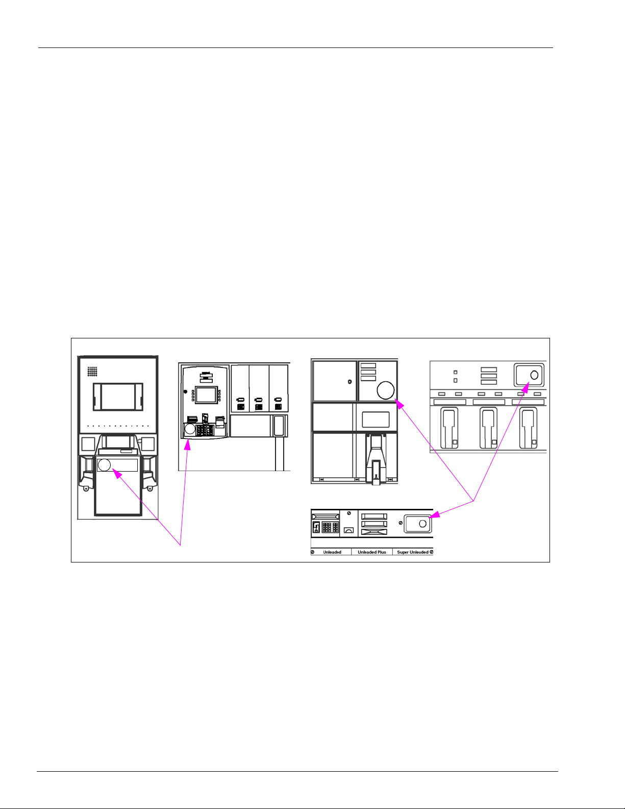
How TRIND Works
TRIND utilizes radio frequency (RF) waves to communicate with a customer’s transponder.
Transmitters located on overhead assemblies transmit radio waves that serve as a “wake up”
call. As a car mounted transponder or hand held transponder enters the transmitter’s effective
read zone, the transponder is activated. The transponder then transmits a code which is
received by the TRIND antennas mounted overhead or on the option doors.
This transmitted code is communicated from the TRIND to the CRIND unit, and from there to
the POS (point of sal
Car mounted transponders are activated when they are within six feet of the front of the
dispenser perpendicular to front of dispenser. Hand held transponders, usually on a k ey chain,
function when pointed at a target graphic on the option door. Two-way communication is
indicated when the option door target graphic light comes on, whether by car mount or hand
held transponder signal.
Figure 1-1: Encore and Eclipse Target Graphic Location
e). The POS system communicates with a host to obtain authorization.
r
P
n
i
m
eli
ary
Page 2 MDE-3664B TRIND Start-Up, Service, and Parts Manual . March 2013

Related Documents
Related Documents
Document
Number Title GOLD Library
MDE-2530 Pump and Dispenser Installation Manual Advantage & Legacy Models
MDE-2531 Start-up and Service Manual for The Advantage Series Service Manual
MDE-2540 The Advantage, Legacy & MPD Series Owners Manual Advantage & Legacy Models
MDE-2562 CRIND Service Manual CRIND and TRIND
MDE-3425 CRIND Retrofit Kit and CRIND Kit Selection Guide CRIND and TRIND
MDE-3591 TRIND Retrofits Kits C00011-002-XXXX CRIND and TRIND
MDE-3801 TRIND Multi 1 Retrofits Kits Manual CRIND and TRIND
MDE-3883 TRIND TIRIS C00011-005 Kit Installation Manual CRIND and TRIND
MDE-3917 TRIND TIRIS Encore 500 Retrofit Kit Installation Manual CRIND and TRIND
MDE-3920 Encore 300 & 500 TRIND Retrofit Kit Installation CRIND and TRIND
MDE-4063 TRIND TIRIS Advantage and MPD-3 Retrofit Kit
MDE-4073 TRIND TIRIS C00011-006 Retrofit Kit Installation CRIND and TRIND
PT-1728 The Advantage Illustrated Parts Manual Parts Manual
PT-1736 The Advantage/MPD/CRIND Illustration Parts Manual Parts Manual
nsta
I
CRIND and TRIND
llation Manual
ary
n
i
TRIND Kit Coverage
The following table provides TRIND kit numbers and the relative system coverage that
applies to each.
m
eli
Kit Number Product Coverage Frequencies Interface Type Tag System
C00011-001 Advantage, MPD-3 LF/UHF T20229-G1 Card Cage Hand Held/Car Mounted
C00011-002 Advantage, MPD-3 LF/UHF (note 2) T20606-G2 Card Cage Hand Held/Car Mounted
C00011-005 Advantage, MPD-3 LF (note1) T20606-G3 Card Cage Hand Held
C00011-004 Encore 500 LF/UHF T20606-G2 Card Cage Hand Held/Car Mounted
C00011-006 Encore 500, Eclipse LF T20606-G3 Card Cage Hand Held
C00011-007 Advantage, MPD-3 LF/UHF (ETSI) (note 3) T20606-G5 Card Cage Hand Held/Car Mounted
C00011-008 Encore 500 LF/UHF (ETSI) T20606-G2 Card Cage Hand Held/Car Mounted
C00011-009 Advantage, MPD-3 LF/UHF T20606-G5 Card Cage Hand Held/Car Mounted
C00011-010 Advantage, MPD-3 LF/UHF T20606-G2 Card Cage Hand Held/Car Mounted
C00012-00X Advantage, MPD-3 HF (note 4) T20538-G1/G2 Card Cage Hand Held
Notes:
1. LF = Low Frequency (134 kHz) send and receive for Hand Held Tags.
2. LF/UHF = Low Frequency (134kHz) send, and Ultra High Frequency (902 MHz)
Held Tags.
3. LF/UHF (ETSI) = Low Frequency (134 kHz) send and Ultra High Frequency (868 MHz) rece
for Hand Held Tags.
4. HF = High Frequency (13.56 MHz) send and receive for Hand Held Tags.
r
P
receive for Car Tags. Low Frequency (134 kHz) for Hand
ive for Car Tags. Low Frequency (134 kHz)
MDE-3664B TRIND Start-Up, Service, and Parts Manual . March 2013 Page 3

TRIND Kit Coverage
This page is intentionally left blank.
r
P
ary
n
i
m
eli
Page 4 MDE-3664B TRIND Start-Up, Service, and Parts Manual . March 2013
2 – Important Safety Information
The EMERGENCY STOP, ALL STOP, and
PUMP STOP buttons at the cashier ’s station
WILL NOT shut off electrical power to the
pump/dispenser. This means that even if you
activate these stops, fuel may continue to flow
uncontrolled.
You must use the TOTAL ELECTRICAL
SHUT-OFF in th e cas e of an emerge nc y a nd not
the console’s ALL STOP and PUMP STOP or
similar keys.
!
WARNING
!
Important Safety Information
Notes: 1) Save this Important Safety Information section
in a readily accessible location.
2) Although DEF is non-flammable, Diesel is
flammable
attached to Diesel dispensers, follow all the
notes in this section that pertain to flammable
fuels.
This section introduces the hazards and safety precautions
associated with installing, inspecting, maintaining or servicing
this product. Before performing any task on this product, read
this safety information and the applicable sections in this
manual, where additional hazards and safety precautions for
your task will be found. Fire, explosion, electrical shock or
pressure release could occur and cause death o r serious injury,
if these safe service procedures are not followed.
Preliminary Precautions
You are working in a potentially dangerous environment of
flammable fuels, vapors, and high voltage or pressures. Only
trained or authorized individuals knowledgeable in the related
procedures should install, inspect, maintain or service this
equipment.
Emergency Total Electrical Shut-Off
The first and most important information you must know is how
to stop all fuel flow to the pump/dispenser and island. Locate
the switch or circuit breakers that shut off all power to all fueling
equipment, dispensing devices, and Submerged Turbine
Pumps (STPs).
. Therefore, for DEF cabinets that are
m
Read the Manual
Read, understand and follow this manua l and any other labels
or related materials supplied with this equipment. If you do not
understand a procedure, call a Gilbarco Authorized Service
Contractor or call the Gilbarco Support Center at
1-800-800-7498. It is imperative to your safety and the safe ty of
others to unders
Follow the Regulations
Applicable information is available in National Fire Protection
Association (NFPA) 30A; Code for Motor Fuel Dispensing
Facilities and Repair Garages, NFPA 70; National Electrical
Code (NEC), Occupatio nal Safety and Health Administr ation
(OSHA) regulations and federal, state, and local codes. All
these regulations must be followed. Failure to install, inspect,
maintain or service this equipment in accordance with these
codes, regulations and standards may lead to legal citations
with penalties or affect the safe use and operation of the
equipment.
Replacement Parts
Use only genuine Gilbarco replacement pa rts and retrofit kit s on
your pump/dispenser. Using parts other than genuine Gilbarco
replacement parts could create a safe ty hazard and violate
ary
local regulations.
tand the procedures before beginning work.
n
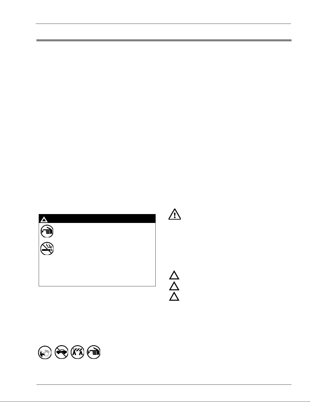
Safety Symbols and Warning Words
i
This section provides important information about warning
symbols and boxes.
Alert Symbol
Total Electrical Shut-Off Before Access
Any procedure that requires access to electrical component s or
the electronics of the dispenser requires total electrical shut off
of that unit. Understand the function and location of this switch
or circuit breaker before inspecting, installing, maintaining, or
servicing Gilbarco equipment.
Evacuating, Barricading and Shutting Off
Any procedure that requires access to the pump/dispenser or
STPs requires the following actions:
• An evacuation of all unauthorized persons and vehicles from
the work area
• Use of safety tape, cones or barricades at the affected unit(s)
• A total electrical shut-off of the affected unit(s)
MDE-3664B TRIND Start-Up, Service, and Parts Manual . March 2013 Page 5
r
P
eli
This safety alert symbol is used in this manual and on
warning labels to alert you to a precaution which must be
followed to prevent po
safety directives that follow this symbol to avoid possib le inj ury
or death.
Signal Words
These signal words used in this manual and on warning labels
tell you the seriousness of particular safety hazards. The
precautions below must be followed to prevent death, injury or
damage to the equipment:
DANGER: Alerts you t
!
which will result in death or serious injury.
WARNING: Alert
!
that could result in death or serious injury.
CAUTION with Alert symbol: Designates a hazard or
!
unsafe
practice which may result in minor injury.
CAUTION without A
unsafe practice which may result in property or
equipment damage.
tential personal safety hazards. Obey
o a hazard or unsafe practice
s you to a ha
lert symbol: Designates a hazard or
zard or unsafe practice
Working With Fuels and Electrical Energy
Prevent Explosions and Fires
Fuels and their vapors will explode or burn, if ignited. Spilled or
leaking fuels cause vapors. Even filling customer tanks will
cause potentially dangerous vapors in the vicinity of the
dispenser or island.
DEF is non-flammable. Therefore, explosion an
warnings do not apply to DEF fluid lines.
d fire safety
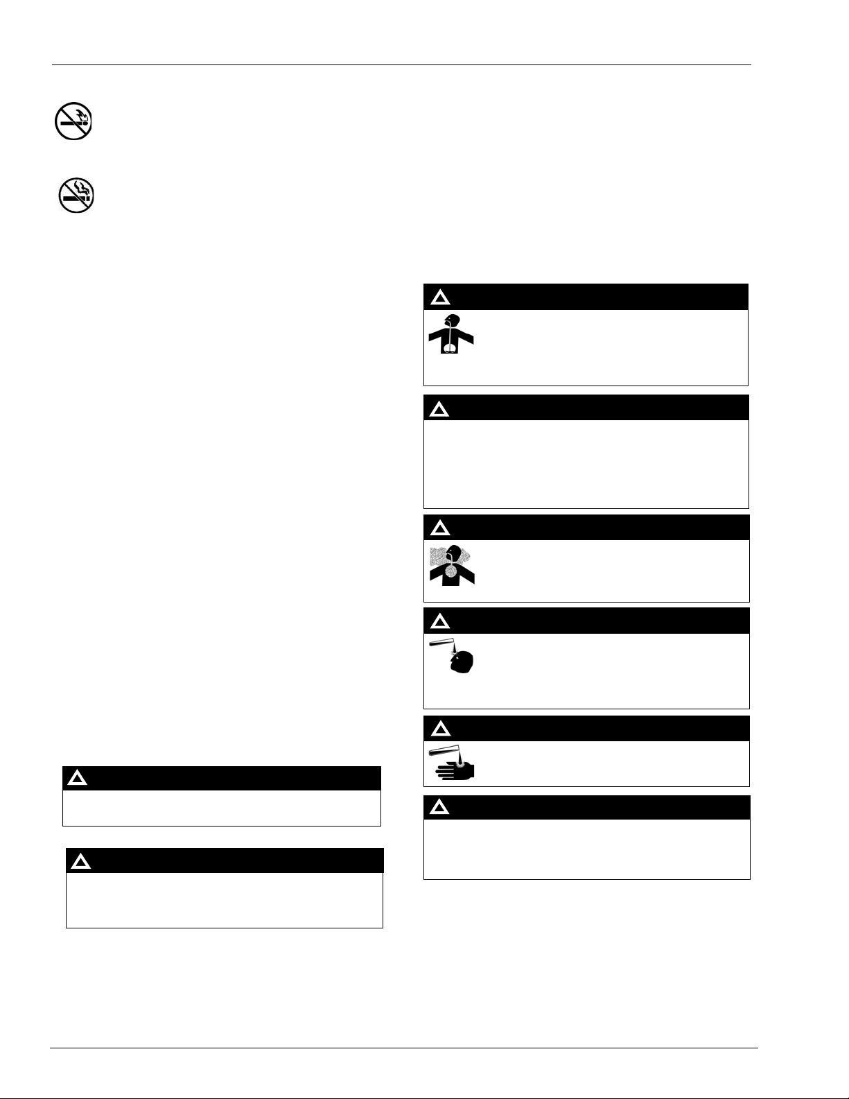
Important Safety Information
The pump/dispenser contains a chemical known to the
State of California to cause cancer.
WARNING
!
The pump/dispenser contains a chemical known to the
State of California to cause birth defects or other
reproductive harm.
WARNING
!
Gasoline/DEF ingested may cause
unconsciousness and burns to internal organs.
Do not induce vomiting. Keep airway open.
Oxygen may be needed at scene. Seek medical
advice immediately.
DEF generates ammonia gas at high er temperatures.
When opening enclosed panels, allow the unit to air out to
avoid breathing vapors.
If respiratory difficulties develop, move victim away from
source of exposure and into fresh air. If symptoms persist,
seek medical attention.
WARNING
!
WARNING
!
Gasoline inhaled may cause unconsciousness
and burns to lips, mouth and lungs.
Keep airway open.
Seek medical advice immediately.
WARNING
!
Gasoline/DEF spilled in eyes may cause burns to
eye tissue.
Irrigate eyes with water for approximately
15 minutes.
Seek medical advice immediately.
WARNING
!
Gasoline/DEF spilled on skin may cause burns.
Wash area thoroughly with clear water.
Seek medical advice immediately.
WARNING
!
DEF is mildly corrosive. Avoid contact with eyes, skin, and
clothing. Ensure that eyewash stations and safety
showers are close to the work location. Seek medical
advice/recommended treatment if DEF spills into eyes.
WARNING
!
No Open Fire
Open flames from matches, lighters, welding torches or
other sources can ignite fuels and their vapors
No Sparks - No Smoking
Sparks from st arting vehicles, starting or using power tools,
burning cigarettes, cigars or pipes can also ignite fuels and their
vapors. Static electricity, including an electrostatic charge on
your body, can cause a spark sufficient to ignite fuel vapors.
Every time you get out of a vehicle, touch the metal of your
vehicle, to discharge any electrostatic charge before you
approach the dispenser island.
Working Alone
It is highly recommended that someone who is capable of
rendering first aid be present during servicing. Familiarize
yourself with Cardiopulmonary Resuscitation (CPR) methods, if
you work with or around high voltages. This information is
available from the American Red Cross . Alw ay s advise the
station personnel about where you will be working, and caution
them not to activate power while you are working on the
equipment. Use the OSHA Lockout/Tagout procedures. If you
are not familiar with this requirement, refer to this information in
the service manual and OSHA documentation.
Working With Electricity Safely
Ensure that you use safe and established practices in working
with electrical devices. Poorly wired devices may cause a fire,
explosion or electrical shock. Ensure that grounding
connections are properly made. Take care that sealing devices
and compounds are in place. Ensure that you do not pinch wires
when replacing covers. Follow OSHA Lockout/Tagout
requirements. Station employees and service contractors need
to understand and comply with this program completely to
ensure safety while the equipment is down.
.
eli
r
In an Emergency
Inform Emergency Personnel
Compile the following information and inform emergency
personnel:
• Location of accident (for example, addre
building, and so on)
• Nature of accident (for example, poss
over by car, burn s, and so on)
• Age of victim (for example, baby, teenager, middle-age,
lderly)
e
• W
hether or not victim has received first aid (for example,
stopped
• Whether or not a victim has vomited (for example, if
swallowe
bleeding by pressure, and so on)
d or inhaled something, and so on)
ss, front/back of
ible heart attack, run
ary
n
i
m
Hazardous Materials
Some materials present inside electronic enclosures may
present a health hazard if not handled correctly . Ensure that you
clean hands after handling equipment. Do not place any
equipment in the mouth.
Page 6 MDE-3664B TRIND Start-Up, Service, and Parts Manual . March 2013
P
IMPORTANT: Oxygen may be needed at scene if gasolin e ha s
been ingested or inhaled. Seek medical advice immediately.
Lockout/Tagout
Lockout/Tagout covers servicing and maintenance of machines
and equipment in which the unexpected energization or st art-up
of the machine(s) or equipment or release of stored energy
could cause injury to employees or personnel. Lockout/Tagout
applies to all mechanical, hydraulic, chemical, or other energy,
but does not cover electrical hazards. Subpart S of 29 CFR Part
1910 - Electrical Hazards, 29 CFR Part 1910.333 contains
specific Lockout/Tagout provision for electrical hazards.
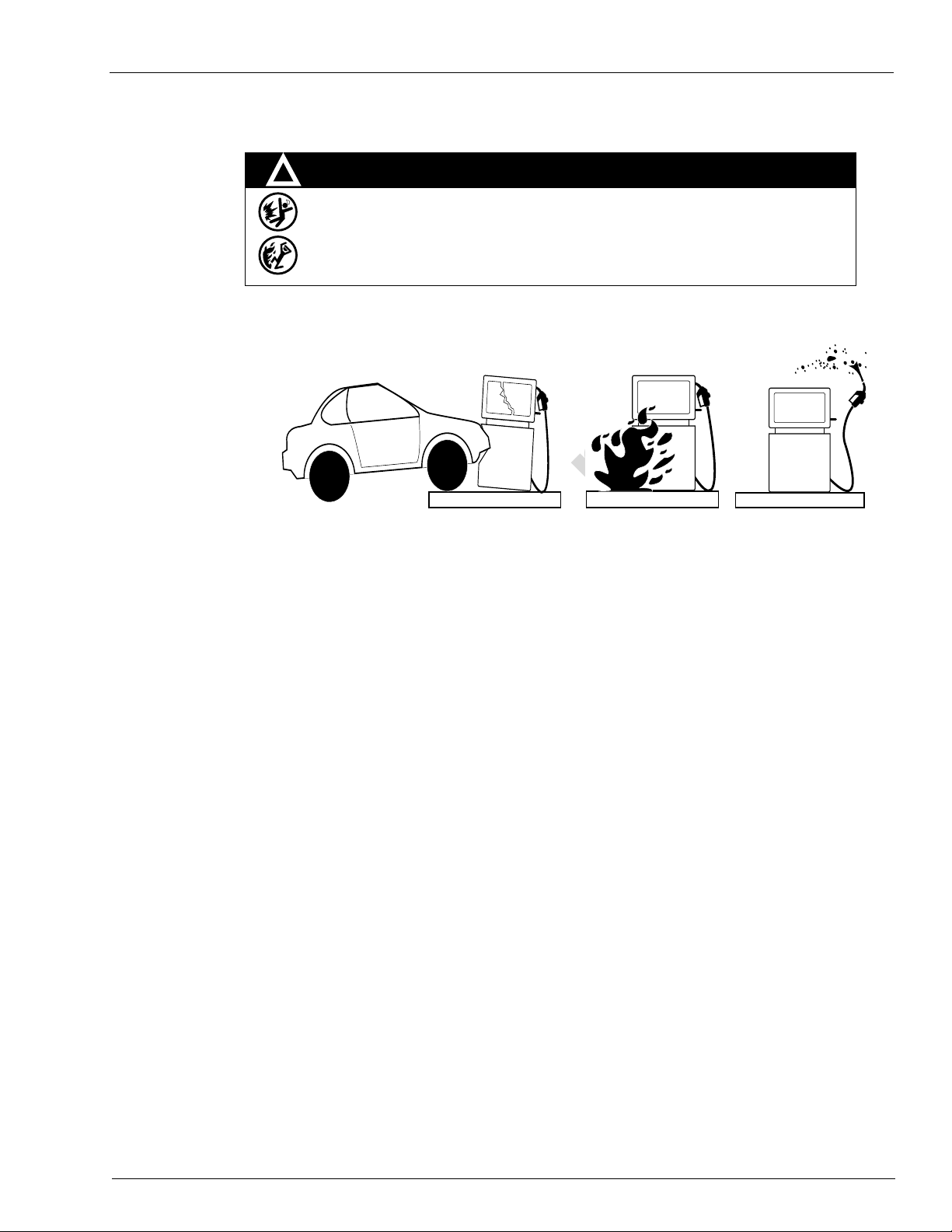
Hazards and Actions
WARNING
Spilled fuels, accidents involving pumps/dispensers, or uncontrolled fuel flow create a
serious hazard.
Fire or explosion may result, causing serious injury or death.
Follow established emergency procedures.
DEF is non-flammable. However it can create a slip hazard. Clean up spills promptly.
!
Collision of a Vehicle with Unit Fire at Island Fuel Spill
The following actions are recommended regarding these hazards:
Important Safety Information
ary
• Do not go near a fuel spill or allow anyone else in the area.
• Use station EMERGENCY CUTOFF immediately. Turn of
• Do not use console E-STOP, ALL STOP, and PUMP STOP to shut off power. These keys do not
remove AC power and do not always stop product flow.
• Take precautions to avoid igniting fuel. Do not allow starting of vehicles in the area. Do not allow
open flames, smoking or power
• Do not expose yourself to hazardous conditions such as fire, spilled fuel or exposed wiring.
• Call emergency numbers.
tools in the area.
m
n
i
f all system circuit br
eakers to the island(s).
eli
r
P
MDE-3664B TRIND Start-Up, Service, and Parts Manual . March 2013 Page 7

Important Safety Information
This page is intentionally left blank.
r
P
ary
n
i
m
eli
Page 8 MDE-3664B TRIND Start-Up, Service, and Parts Manual . March 2013
3 – Systems Overview
Overhead Antenna Assembly
Side A
T20231-G1
LF Transmitter (134kHz Intentional
Radiator)
Q13579-01
Control Data
UHF Receiver Module
902 - 928 MHz
115 VAC
(FROM Dispenser
AC POWER
DISTRIBUTION)
RS-232 RS-232
Gateway Board
T20128
SERIAL DATA
to CRIND logic boards
(Dispenser Electronics)
J7 J8
J4
P187
P250
P185
22VDC,
5VDC, GND
5VDC,
GND
22VDC,
5VDC, GND
J6
J3
22VDC, 5VDC, GND
22VDC, 5VDC, GND
J5 J5
J2A J2B JA JB
LF TX
UHF RX
Overhead Antenna Assembly
Side B
T20231-G1
UHF RX
LF TX
POWER REGULATING
Circuit Board
T20138-G1
P177P179P176
P175
P178
Light Board Assembly
(T20295, T20446)
on Dispenser Bezel Face
(Side A)
P181
P180,
P182
RS-232, Digital
Control and Light
Control Circuit
P180,
P182
P181
RS-232, Digital
Control and Light
Control Circuit
When overhead antennas are not part of
the product, Dummy Load R20526-G1
plugs into JA and JB. J2A and J2B are
left unconnected.
DATA CONTROL BOARD
Q13563-01 or -02
60VAC
Power Supply
R20600-G1
AC Po wer
EMC Filter
Q10895-01
Micro-Reader
Q13551-01
(134 KHz
Intentional)
Micro-Reader
Q13551-01
(134 KHz
Intentional)
T20143
Bezel
Antenna
R20522-G2
Cable
T20143
Bezel
Antenna
R20522-G2
Cable
Light Board Assembly
(T20295, T20446)
on Dispenser Bezel Face
(Side B)
RS-232
LF TX/RX
LF TX/RX
RS-485
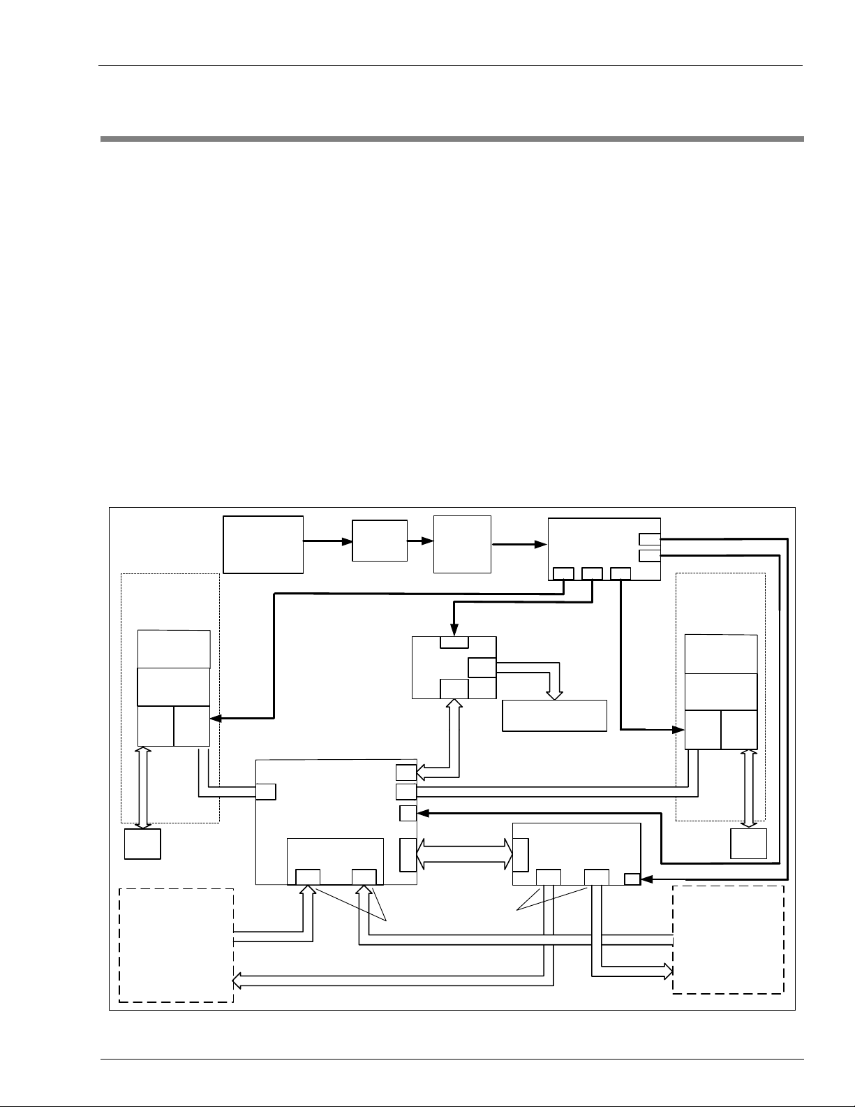
Full Systems
The Full System product is an option available as a retrofit kit or factory installed equipment
on the Advantage, MPD-3 and Encore, and Eclipse lines of fuel dispensers. The TRIND
device is connected to the CRIND via a gateway or serial interface board. In this application
TRIND is a software slave to the CRIND and the associated POS controller/host. This means
that a properly working TRIND system will look for and read tags, but only when told to by
the controller, through the CRIND application.
This system is to be installed in accordance with all Underwriter’s Laboratories (UL), Federal
Communications Commission (FCC), federal, state and local regulations associated with it.
The following illustrations depict the system component used in the Original, Advantage,
MPD-3, and Encore full systems.
Full Systems
Figure 3-1: Original Full System Block Diagram
ary
n
i
m
eli
r
P
MDE-3664B TRIND Start-Up, Service, and Parts Manual . March 2013 Page 9
Full Systems
O
v
e
r
h
e
a
d
A
n
t
e
n
n
a
A
s
s
e
m
b
l
y
S
i
d
e
A
T
2
0
2
3
1
-
G
1
L
F
T
r
a
n
s
m
i
t
t
e
r
(
1
3
4
k
H
z
I
n
t
e
n
t
i
o
n
a
l
R
a
d
i
a
t
o
r
)
Q
1
3
5
7
9
-
0
1
C
o
n
t
r
o
l
D
a
t
a
U
H
F
R
e
c
e
i
v
e
r
M
o
d
u
l
e
R
I
-
R
F
M
-
H
R
E
A
9
0
2
-
9
2
8
M
H
z
1
1
5
V
A
C
(
F
R
O
M
D
i
s
p
e
n
s
e
r
A
C
P
O
W
E
R
D
I
S
T
R
I
B
U
T
I
O
N
)
R
S
-
2
3
2
R
S
-
2
3
2
G
a
t
e
w
a
y
B
o
a
r
d
T
2
0
1
2
8
S
E
R
I
A
L
D
A
T
A
t
o
C
R
I
N
D
l
o
g
i
c
b
o
a
r
d
s
(
D
i
s
p
e
n
s
e
r
E
l
e
c
t
r
o
n
i
c
s
)
J
7
J
8
J
4
P
1
8
7
P
2
5
0
P
1
8
5
2
2
V
D
C
,
5
V
D
C
,
G
N
D
5
V
D
C
,
G
N
D
2
2
V
D
C
,
5
V
D
C
,
G
N
D
J
6
J
3
2
2
V
D
C
,
5
V
D
C
,
G
N
D
2
2
V
D
C
,
5
V
D
C
,
G
N
D
J
5
J
5
J
2
A
J
2
B
J
A
J
B
O
v
e
r
h
e
a
d
A
n
t
e
n
n
a
A
s
s
e
m
b
l
y
S
i
d
e
B
T
2
0
2
3
1
-
G
1
L
i
g
h
t
B
o
a
r
d
A
s
s
e
m
b
l
y
(
T
2
0
6
0
1
-
G
X
o
r
M
0
1
5
6
0
A
0
0
X
)
o
n
D
i
s
p
e
n
s
e
r
B
e
z
e
l
F
a
c
e
(
S
i
d
e
A
)
P
O
W
E
R
R
E
G
U
L
A
T
I
N
G
C
i
r
c
u
i
t
B
o
a
r
d
T
2
0
3
1
4
-
G
1
P
1
7
7
P
1
7
9
P
1
7
6
P
1
7
5
P
1
7
8
L
i
g
h
t
B
o
a
r
d
A
s
s
e
m
b
l
y
(
T
2
0
6
0
1
-
G
X
o
r
M
0
1
5
6
0
A
0
0
X
)
o
n
D
i
s
p
e
n
s
e
r
B
e
z
e
l
F
a
c
e
(
S
i
d
e
A
)
P
1
8
1
P
1
8
2
R
S
-
2
3
2
,
D
i
g
i
t
a
l
C
o
n
t
r
o
l
a
n
d
L
i
g
h
t
C
o
n
t
r
o
l
C
i
r
c
u
i
t
P
1
8
2
P
1
8
1
R
S
-
2
3
2
,
D
i
g
i
t
a
l
C
o
n
t
r
o
l
a
n
d
L
i
g
h
t
C
o
n
t
r
o
l
C
i
r
c
u
i
t
M
0
0
8
7
8
A
0
0
2
M
0
0
8
7
8
A
0
0
2
M
0
0
8
7
8
A
0
0
2
C
a
b
l
e
C
a
b
l
e
C
a
b
l
e
W
h
e
n
o
v
e
r
h
e
a
d
a
n
t
e
n
n
a
s
a
r
e
n
o
t
p
a
r
t
o
f
t
h
e
p
r
o
d
u
c
t
,
D
u
m
m
y
L
o
a
d
R
2
0
5
2
6
-
G
1
p
l
u
g
s
i
n
t
o
J
A
a
n
d
J
B
.
J
2
A
a
n
d
J
2
B
a
r
e
l
e
f
t
u
n
c
o
n
n
e
c
t
e
d
.
R
2
0
7
7
3
-
G
2
,
d
o
o
r
c
a
b
l
e
,
p
r
o
v
i
d
e
s
p
o
w
e
r
a
n
d
R
S
2
3
2
c
o
m
m
u
n
i
c
a
t
i
o
n
s
R
2
0
7
7
3
-
G
2
,
d
o
o
r
c
a
b
l
e
,
p
r
o
v
i
d
e
s
p
o
w
e
r
a
n
d
R
S
2
3
2
c
o
m
m
u
n
i
c
a
t
i
o
n
s
X
i
s
c
o
l
o
r
o
f
L
E
D
s
D
A
T
A
C
O
N
T
R
O
L
B
O
A
R
D
Q
1
3
5
6
3
-
0
2
o
r
-
0
4
5
M
H
z
(
U
H
F
C
l
o
c
k
-
s
e
l
e
c
t
e
d
b
y
j
u
m
p
e
r
)
1
0
M
H
z
(
L
o
c
a
l
C
l
o
c
k
-
n
o
t
s
e
l
e
c
t
e
d
f
o
r
t
h
i
s
a
p
p
l
ic
a
t
i
o
n
)
2
4
V
A
C
P
o
w
e
r
S
u
p
p
l
y
A
C
P
o
w
e
r
E
M
C
F
i
l
t
e
r
Q
1
0
8
9
5
-
0
1
M
i
c
r
o
-
R
e
a
d
e
r
Q
1
3
5
5
1
-
0
1
(
1
3
4
K
H
z
I
n
t
e
n
t
i
o
n
a
l
)
M
i
c
r
o
-
R
e
a
d
e
r
Q
1
3
5
5
1
-
0
1
(
1
3
4
K
H
z
I
n
t
e
n
t
i
o
n
a
l
)
M
0
0
8
7
8
A
0
0
2
C
a
b
l
e
T
2
0
5
2
4
B
e
z
e
l
A
n
t
e
n
n
a
R
2
0
5
2
2
-
G
2
C
a
b
l
e
T
2
0
5
2
4
B
e
z
e
l
A
n
t
e
n
n
a
R
2
0
5
2
2
-
G
2
C
a
b
l
e
R
S
-
2
3
2
L
F
T
X
/
R
X
L
F
T
X
/
R
X
U
H
F
R
C
V
U
H
F
R
C
V
L
F
T
X
L
F
T
X
R
S
-
4
8
5
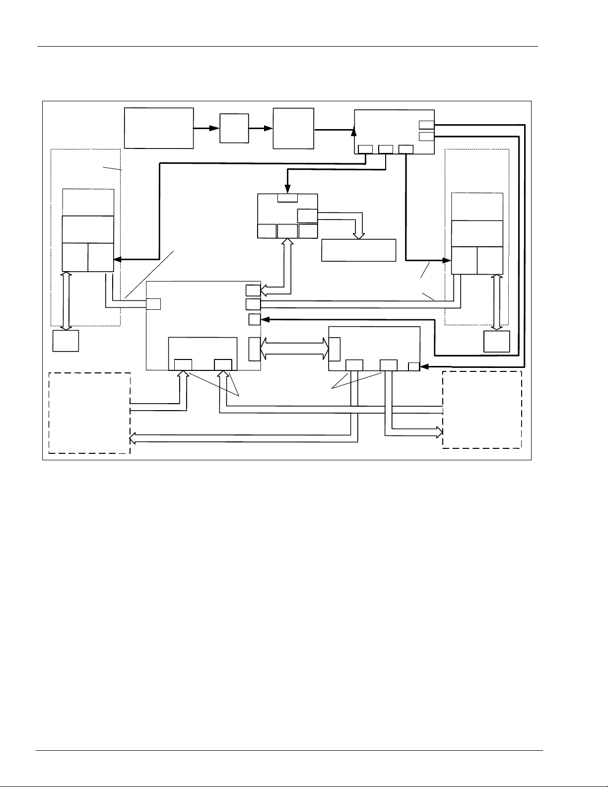
Figure 3-2: Advantage Series Full System Block Diagram
ary
n
i
m
Page 10 MDE-3664B TRIND Start-Up, Service, and Parts Manual . March 2013
P
r
eli
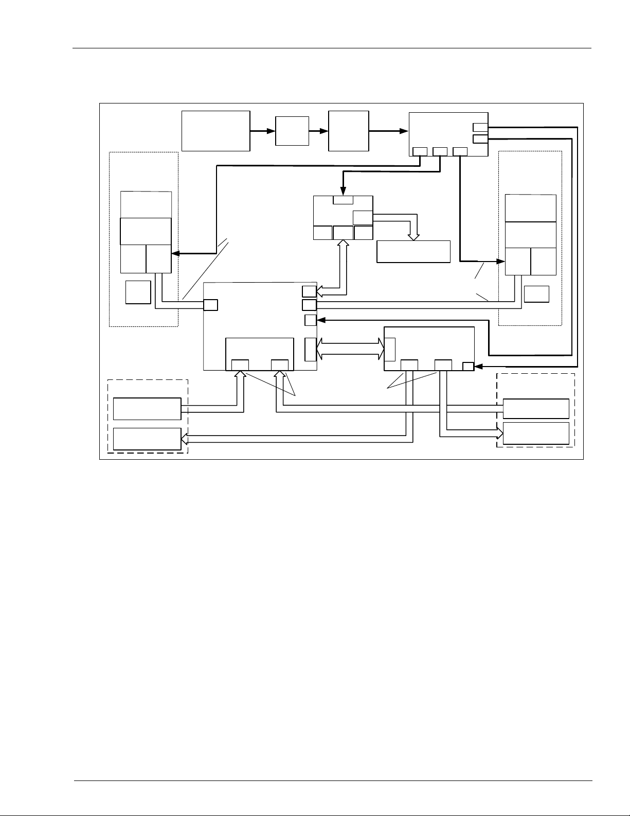
Figure 3-3: Encore Full System Block Diagram
Overhead Antenna Assembly
Side A
LF Transmitter (134kHz Intentional
Radiator)
Q13579-01
Control Data
UHF Receiver Module
RI-RFM-HRUA
902 - 928 MHz
115 VAC
(FROM Dispenser
AC POWER
DISTRIBUTION)
RS-232
RS-232
Gateway Board
T20128
SERIAL DATA
to CRIND logic boards
(Dispenser Electronics)
P187
P250
P185
22VDC, 5VDC,
GND
5VDC,
GND
22VDC,
5VDC, GND
22VDC, 5VDC, GND
22VDC, 5VDC, GND
J2A J2B
LF Transmit Antenna
UHF Receive Antenna
Overhead Antenna Assembly
Side B
LF Transmit Antenna
UHF Receive Antenna
Light Board Assembly
M01218A00X
on Dispenser Bezel Face
(Side A)
POWER REGULATING
Circuit Board
T20314-G1
P177P179P176
P175
P178
Light Board Assembly
M01218A00X
on Dispenser Bezel Face
(Side A)
P182
RS-232, Digital
Control and Light
Control Circuit
P182
RS-232, Digital
Control and Light
Control Circuit
J1A
J3A
J3B
J1B
M00878A001
M00878A001
M00878A001
Cable
Cable
Cable
Tuner Board T20579
Tuner Board T20579
Q13851-01
Q13851-01
WO3889
WO3889
When overhead antennas are not part of
the product, Dummy Load R20526-G1
plugs into JA and JB. J2A and J2B are
left unconnected.
R20773-G2, door cable,
provides power and RS232
communications
R20773-G2, door cable,
provides power and RS232
communications
X is color of LEDs
DATA CONTROL BOARD
Q13563-02 or -04
5 MHz (UHF Clock - selected
by jumper)
10 MHz (Local Clock - not
selected for this application)
24 VAC
Power Supply
AC Power
EMC Filter
Q10895-01
Micro-Reader
Q13551-01
(134 KHz
Intentional)
Micro-Reader
Q13551-01
(134 KHz
Intentional)
M00878A001
Cable
Encore
Antenna
(on board
Encore
keytag
Antenna
(on board
RS-232
RS-485
UHF RCVUHF RCV
LF TX
LF TX
Full Systems
r
P
eli
i
m
ary
n
MDE-3664B TRIND Start-Up, Service, and Parts Manual . March 2013 Page 11
Hand Held Only Tag System Overview
115 VAC
(FROM Dispenser
AC POWER
DISTRIBUTION)
R20580-G1
24 VAC
Class II Energy
Limiting
Transformer
R20719-G1
115 VAC
T20524
Bezel
Antenna
T20524
Bezel
Antenna
Enhanced Gateway
Board
T20678
S
e
r
i
a
l
D
a
t
a
to CRIND™ logic boards
(Dispenser Electronics)
RS-232, +22VDC, +5VDC, GND
RS-232, +22VDC, +5VDC, GND
P282A P282BP250
P185
22VDC,
5VDC,
GND
Light Board Assembly
(T20601-G1)
on Dispenser Bezel Face
(Side B)
RFID Power Supply
T20314-G1
P174
P177P178P176
P175
P179
Light Board Assembly
(T20601-G1)
on Dispenser Bezel Face
(Side A)
P181P182
RI-STU-MRD1
Micro-Reader
(134kHz
Intentional
Radiator)
RS-232, Digital
Control and Light
Control Circuit
P182P181
RI-STU-MRD1
Micro-Reader
(134kHz
Intentional
Radiator)
RS-232, Digital
Control and Light
Control Circuit
EMI Line Filter
Q10895-01
115 VAC
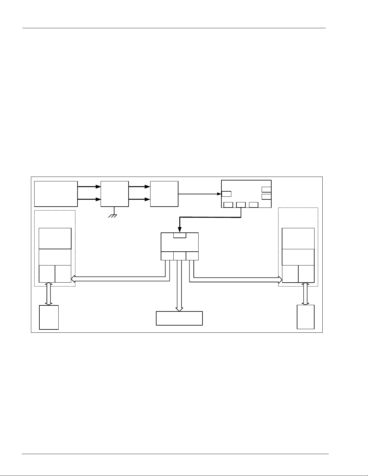
Hand Held Only Tag System Overview
This product is an option available as a retrofit kit or factory installed equipment in
Advantage, MPD-3, and Encore lines of fuel dispensers. The TRIND Enhanced Gateway
Board (T20678) manages RFID processing and provides simple, generic event messages to the
pump electronics via Transistor-Transistor Logic (TTL). In this application, TRIND is a
software slave to the CRIND and the associated POS controller/host. This means that a
properly working Low Frequency (LF) TRIND system will look for and read tags, but only
when told to by the controller, through the CRIND application.
This system is to be installed in accordance with all UL, FCC, federal, state and local
regulations. The following block diagram depicts the components for the Hand Held Only Tag
System.
Figure 3-4: Hand Held Only Tag System Block Diagram
ary
n
i
m
eli
r
P
Page 12 MDE-3664B TRIND Start-Up, Service, and Parts Manual . March 2013
Card Cage Assemblies Major Hardware Components
1
2
3
5
4
4 – Major Hardware Components
Card Cage Assemblies
There are four main card cage versions used for the TRIND system. These four card cages are
the T20229-G1, T20606-G2, T20606-G3, and the T20606-G5. The T20229 card cage is no
longer available and is discussed in this manual simply for the service and support of the
installed base. There are other G-levels of the T20606 card cage, but these are variations of the
-G2 and -G3. Therefore, being familiar with these base card cages and their parts will provide
the technician with valuable information in servicing the other G-levels if encountered.
Note: Many parts look similar in the T20229 and T20606 card
same. Always replace the removed part with the same part number or risk voiding the
UL listings, FCC certifications, warranty, if applicable.
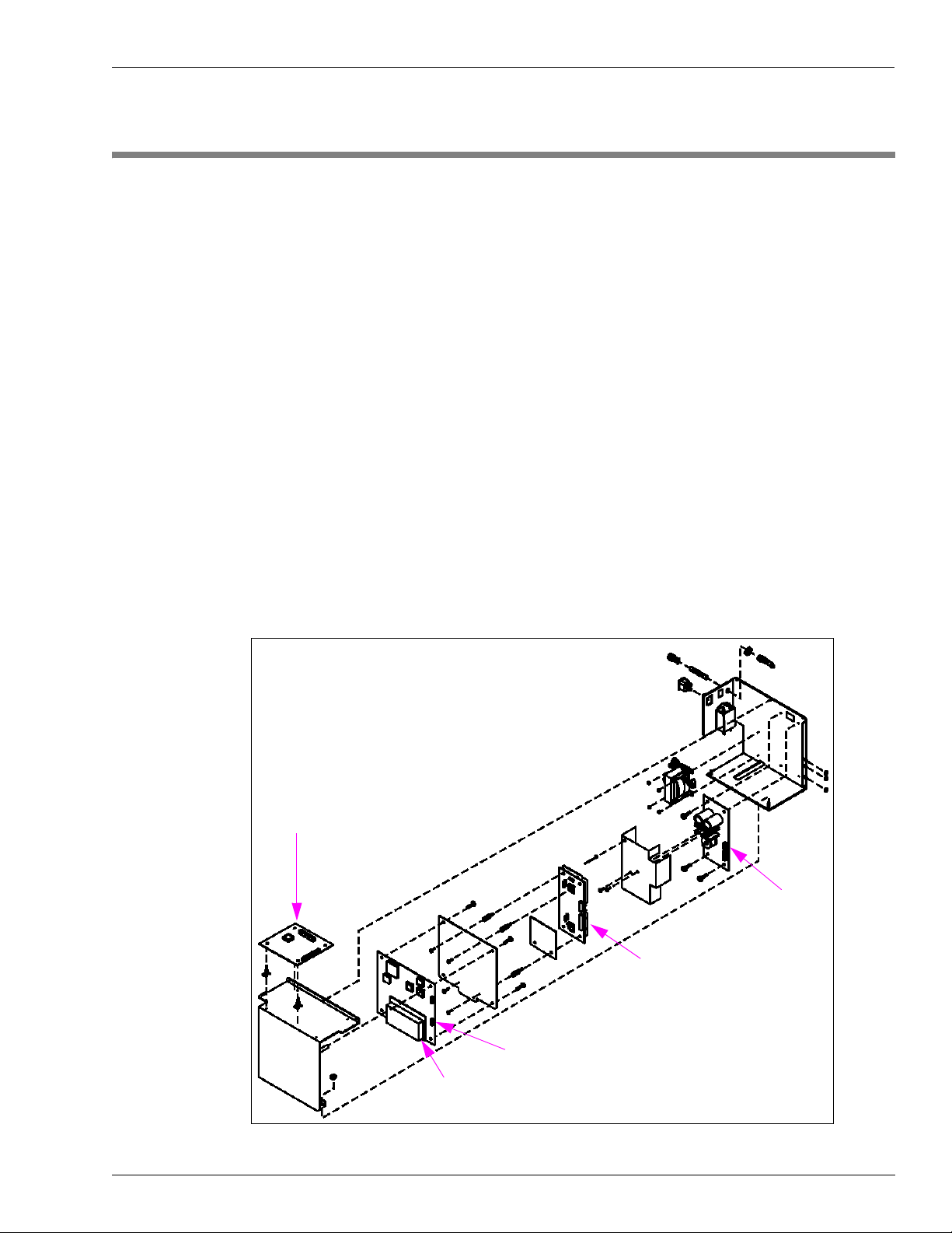
T20229-G1 Card Cage Assembly
The T20229 card cage was the installed card cage for the original Mobil Speedpass program.
With a few cable changes, this card cage can be replaced by the T20606-G2, which contains
the new Multi-Port DCB from T exas Instruments.
cages, but they are not the
Figure 4-1: Card Cage Assembly T20229-G1
Preliminary
MDE-3664B TRIND Start-Up, Service, and Parts Manual . March 2013 Page 13
Major Hardware Components Card Cage Assemblies
1
8
9
10
11
7
6
5
4
3
2
12
13
T20229-G1 Card Cage Assembly Parts List
Item Description Part Number
1 Power Supply PCB T20138-G1
2 Transmitter PCB Assembly Q13579-01
3 Data Control Board Q13563-01
4 UHF Receiver Assembly on DCB Q13564-01
5 Gateway Board T20128-G1
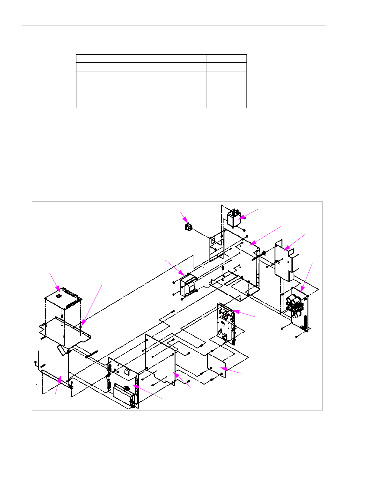
T20606-G2 Card Cage Assembly
The T20606-G2 card cage is the updated version of the T20229-G1. It features a Multi-Port
DCB, LF Transmitter and a High-Gain UHF receiver. It also has a card cage harness, which
reduces the number of field connections that must be made (compared to the T20229). This
card cage comes ready to mount in an Encore unit, and is easily modified to also work in
Eclipse, Advantage and MPD-3 units.
Figure 4-2: Card Cage Assembly T20606-G2
na
i
m
li
ry
re
P
Page 14 MDE-3664B TRIND Start-Up, Service, and Parts Manual . March 2013
Card Cage Assemblies Major Hardware Components
1
4
2
5
3
T20606-G2 Card Cage Assembly Parts List
Item Description Part Number
1 TRIND Gateway PCB T20128-G3
2 Circuit Board Support Q10651-16
3 TRIND PCB Bracket M00624A001
4 Multi-Port Data Control Board Q13563-04
5 Radio PCB Shield R20545-G1
6 PCB Insulator Board R20590-01
7 Low Frequency Transmitter Module Q13579-01
8 24 VAC Transformer R20719-G1
9 Recessed Power Receptacle R20206-G14
10 10 AMP EMI Filter Q10895-01
11 TRIND PCB Shield Bracket M00621A001
12 Regulator PCB Shield T20198-01
13 Regulator PCB T20314-G1
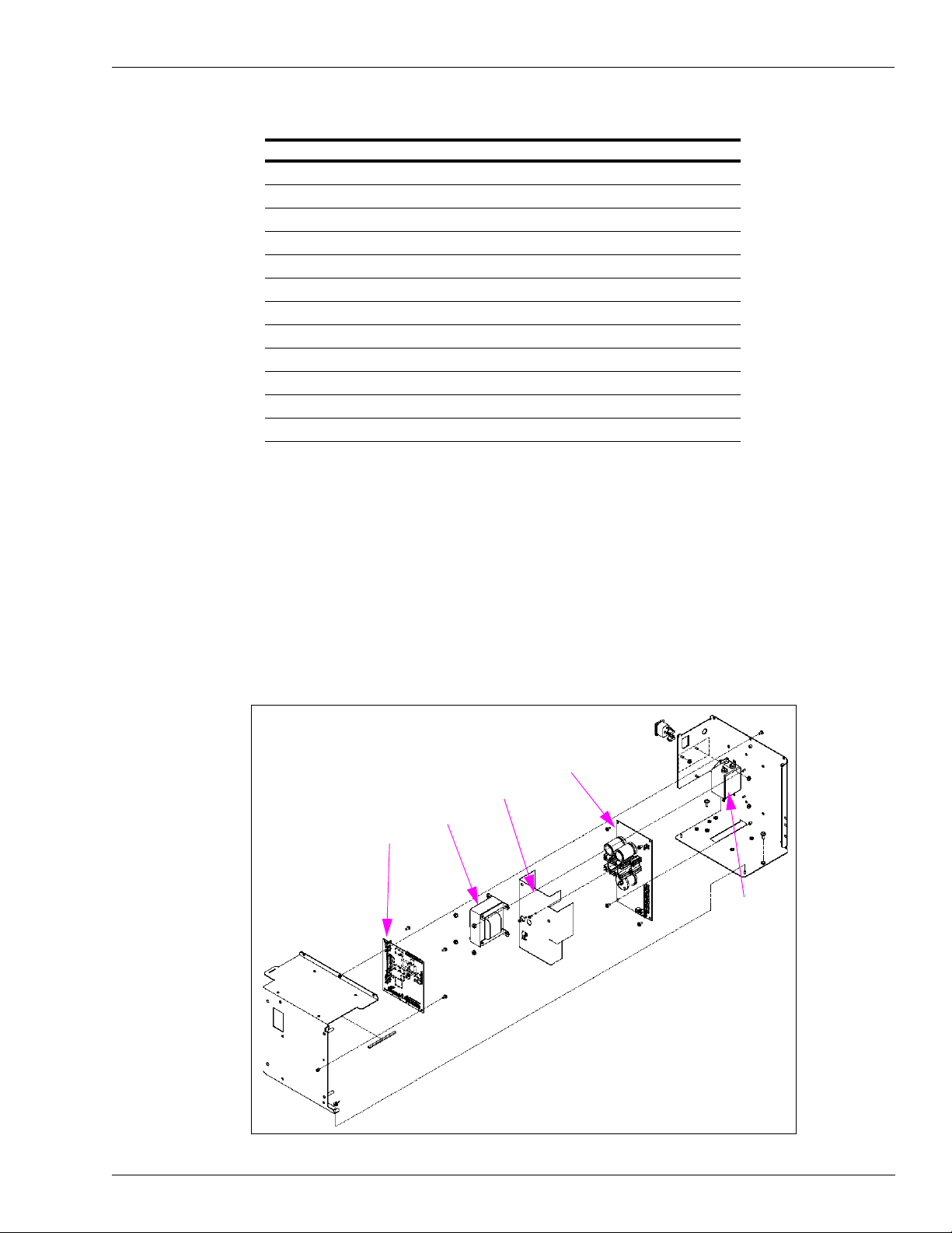
T20606-G3 Card Cage Assembly
The T20606-G3 card cage supports “keytag only” operation and features an Enhanced
Gateway board, which serves as the local controller for the RF modules (taking the place of
the DCB) and the protocol handler for payment messaging (to CRIND or other Host
Controller device). This card cage comes ready to mount in Encore, Advantage, Eclipse and
MPD-3, with no modifications required.
Figure 4-3: Card Cage Assembly T20606-G3
Preliminary
MDE-3664B TRIND Start-Up, Service, and Parts Manual . March 2013 Page 15
Major Hardware Components Card Cage Assemblies
1
8
9
10
11
7
6
5
4
3
2
12
13
T20606-G3 Card Cage Assembly Parts List
Item Description Part Number
1 Regulator PCB T20314-G1
2 Shield, Regulator, PCB T20198-01
3 Transformer, 24 VAC R20719-G1
4 Enhanced Gateway PCB T20678-G1
5 Filter, EMI, 10 AMP Q10895-01
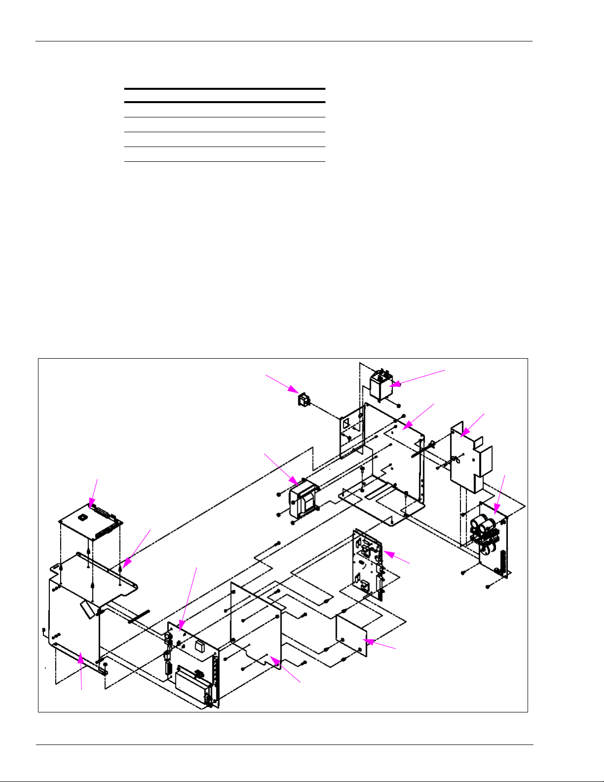
T20606-G5 Card Cage Assembly
The T20606-G5 card cage is a variation of the T20606-G2 card cage required for many
international “full system” TRIND applications (Europe and southeast Asia). It features a
European Telecommunications Standards Institute (ETSI) Data Control Board (DCB), LF
Transmitter and a High-Gain UHF receiver. It also has a card cage harness, which reduces the
number of field connections that must be made (compared to the original T20229). This card
cage comes ready to mount in an Encore unit, and is easily modified to also work in Eclipse,
Advantage and MPD-3 units.
ry
Figure 4-4: Card Cage Assembly T20606-G5
na
i
m
li
re
P
Page 16 MDE-3664B TRIND Start-Up, Service, and Parts Manual . March 2013
Card Cage Assemblies Major Hardware Components
1
2
2
T20606-G5 Card Cage Assembly Parts List
Item Description Part Number
1 TRIND Gateway PCB T20128-G3
2 Circuit Board Support Q10651-16
3 TRIND PCB Bracket M00624A001
4 ETSI Data Control Board Q13563-07
5 Radio PCB Shield R20545-G1
6 PCB Insulator Board R20590-01
7 Low Frequency Transmitter Module Q13579-01
8 24 VAC Transformer R20719-G1
9 Recessed Power Receptacle R20206-G14
10 10 AMP EMI Filter Q10895-01
11 TRIND PCB Shield Bracket M00621A001
12 Regulator PCB Shield T20198-01
13 Regulator PCB T20314-G1
Disassembly and Installation For MPD®-3 Units with SID Displays
In some older installations, a screw and two nuts were installed under the Card Cage on side B
of a unit. This causes the installed card cage to rest at an angle, higher on side B. This
hardware must remain in place in order to prevent contact between the Card Cage and the SID
boards when the bezel door is closed.
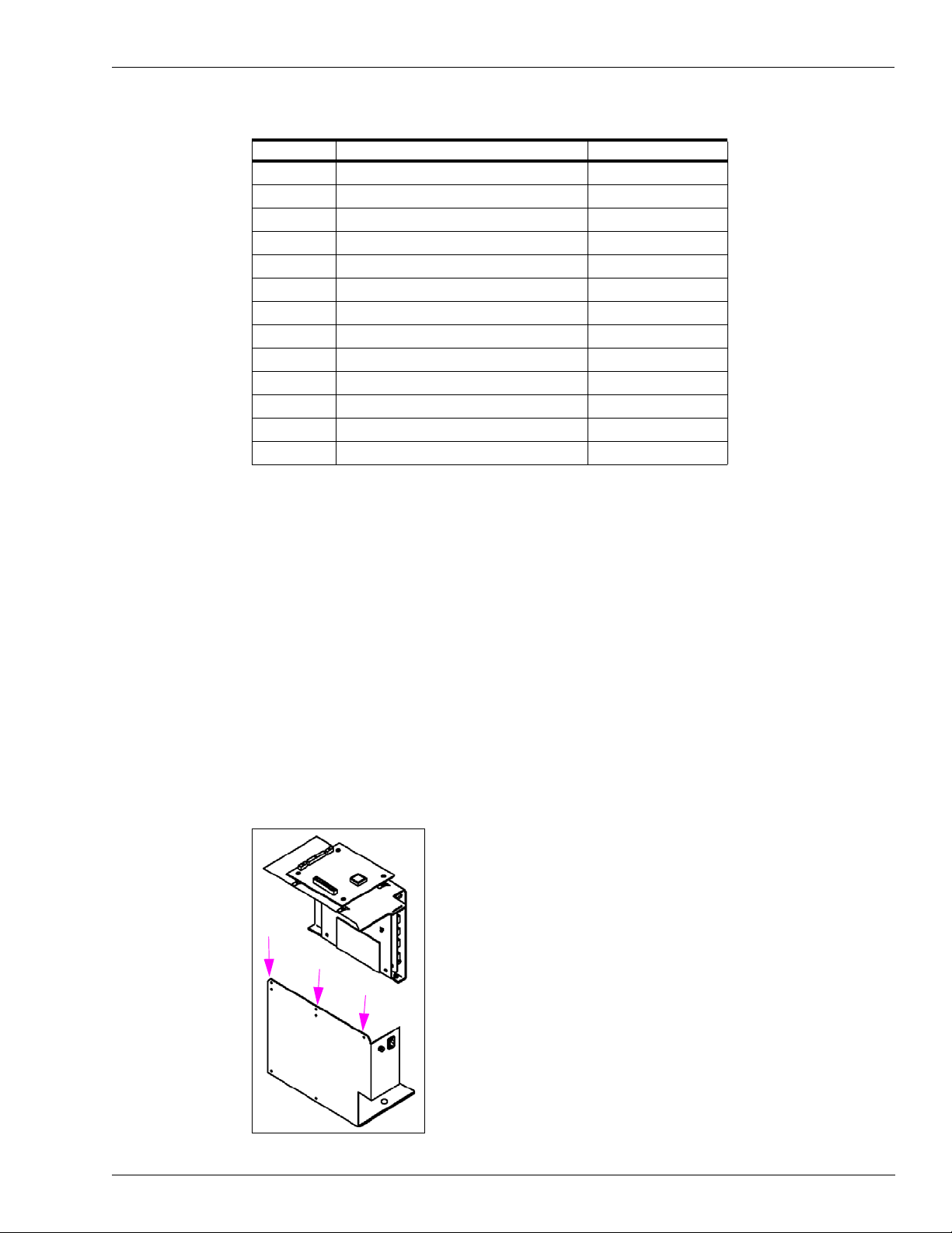
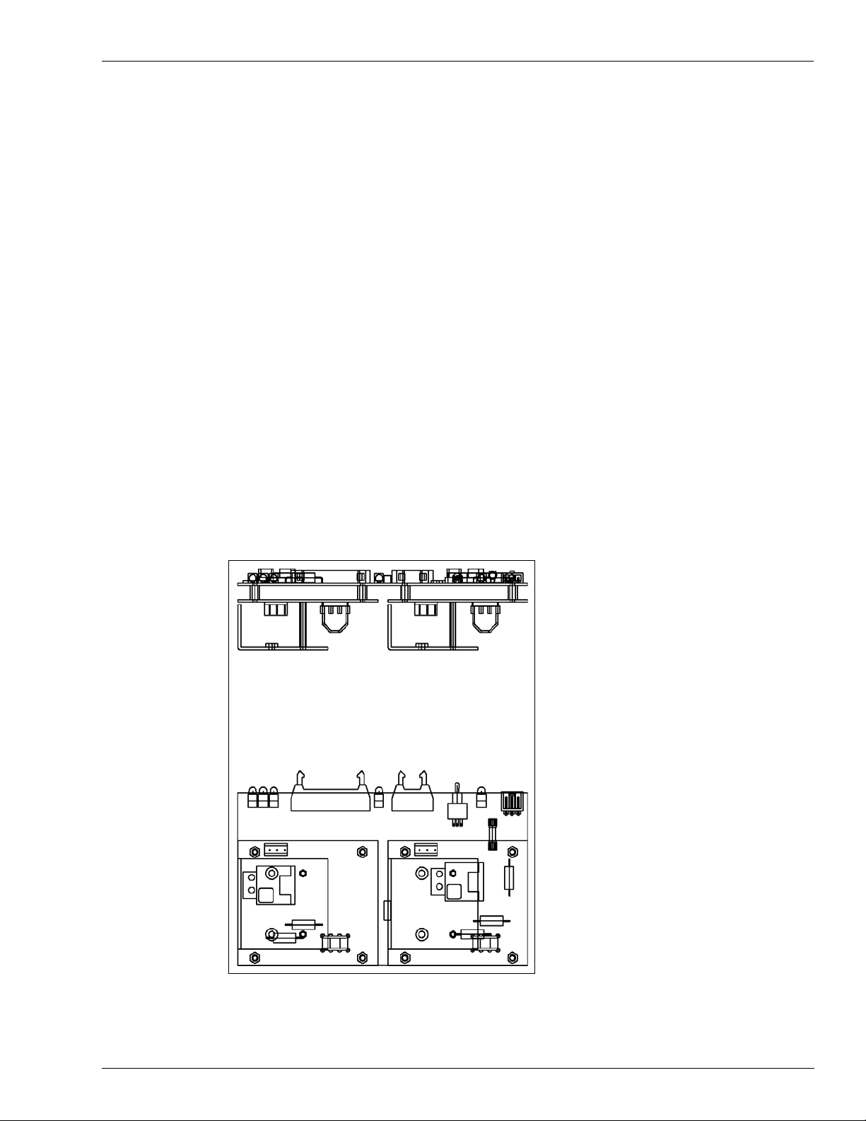
Disassembly and Installation For All MPD-3 Units
In field retrofits, the TRIND units’ top (center) screw from the card cage was removed, and
replaced by tie wraps at either side after the card cage was installed in the cabinet. The card
cage can only be removed or installed when separated into two pieces. See Figure4-5 for
locations of the screw (1) and tie wraps (2).
Figure 4-5: Screw and Tie Wrap Locat ions
Preliminary
MDE-3664B TRIND Start-Up, Service, and Parts Manual . March 2013 Page 17
Major Hardware Components Card Cage Assemblies
5V
GND
22V
GND GND
5V
22V
GND
Note: P176, 177, and P178 are identical.
JP1 through JP4:
must be unique
address for each
dispenser at site
22V
5V
5V
AC EMI Line Filter Q10895
AC EMI Line Filter Q10895-01, is a Corcom dual T section RFI power line filter . These filters
are well suited for low impedance loads where noisy RFI environments are present. They
control pulsed, continuous and/or intermittent interference, insuring protection of the TRIND
equipment from power line noise in addition to protecting the line from equipment noise.
Transformers R20600 and R20719
Transformer R20600-G1 is used in T20229-G2 card cage assembly. Transformer R20719-G1
is used in T20606-G2 LF/UHF full system, and T20606-G2 Enhanced Gateway system card
cages. Each transformer performs step down of 120VAC to a usable level for the RFID Power
supply. The R20600 steps 120VAC down to 60VAC, which is used by the T20138-G1 Power
Supply board. The R20719 steps 120VAC down to 24VAC, which is used by the T20314-G1
Power Supply board.
Power Supply Boards T20138 and T20314
Power Supply Board T20138-G1 is used in T20229-G1 full system card cage assembly. Power
Supply Board T20314-G1 is used in T20606 line of card cages. The supplies take the outpu t of
their respective AC to AC transformers and make the proper DC voltages for use by the
TRIND system components. Both supplies utilize a gate-driven MOSFET (for +22VDC) and a
buck switched mode power supply (for +5VDC). Both supplies monitor the current on the
output to turn off the gate drive, rather than fail permanently, should one of the TRIND system
components develop a voltage problem. This arrangement allows for any of the outputs to be
shorted directly to ground with out harming the power supply because it turns itself off until
the problem is discovered and removed, and AC power is cycled.
m
li
na
i
ry
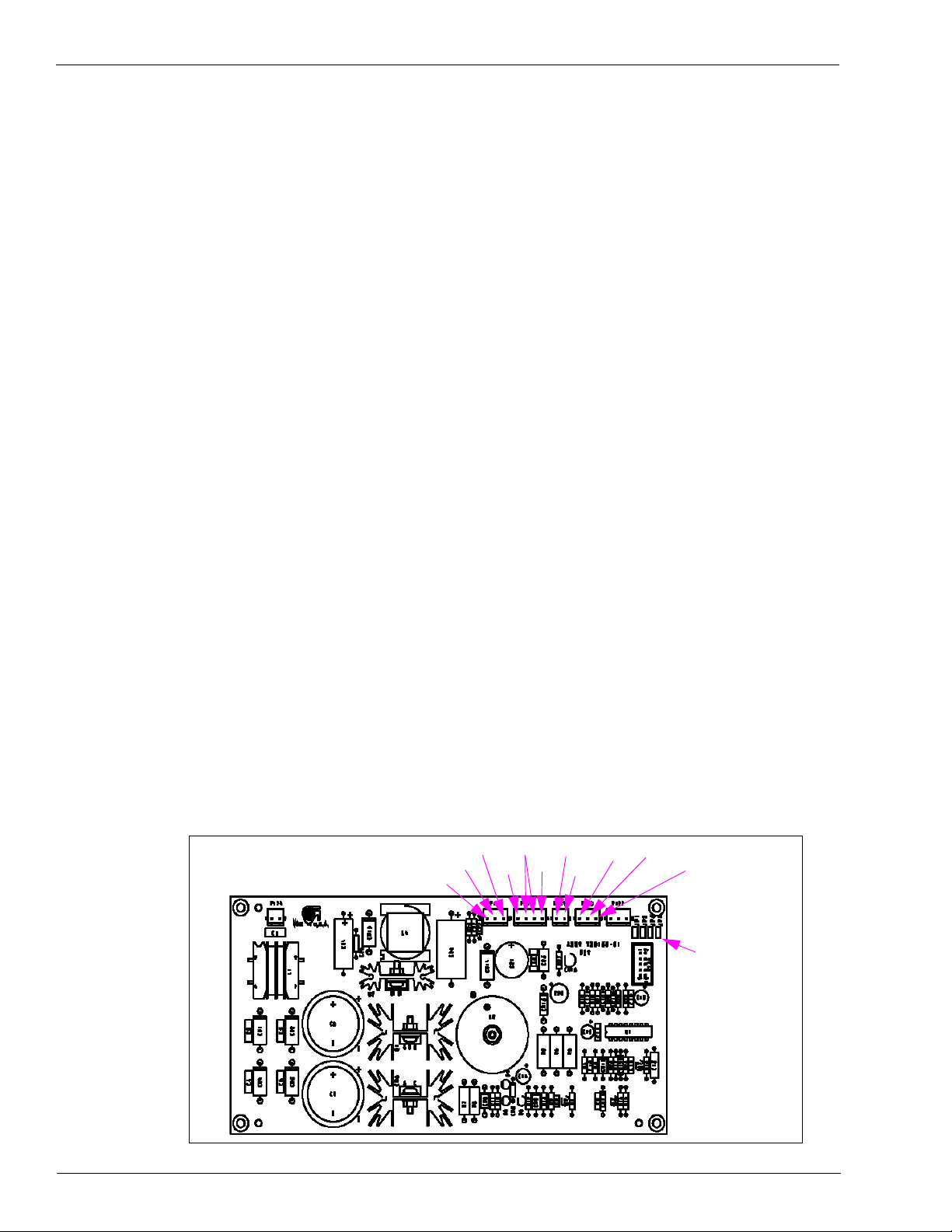
T20138 Power Supply Board.
This board has jump-jack locations to set the dither sync (“Glossary” on page 1) address for
the TRIND unit, with a 10-position ribbon cable (at P173) that goes to the DCB (J6). These
addresses
Figure 4-6: Power Supply Board T20138
only matter to the site itself, not the pump or CRIND.
re
P
Page 18 MDE-3664B TRIND Start-Up, Service, and Parts Manual . March 2013
Card Cage Assemblies Major Hardware Components
5V
GND
22V
GND
GND
5V
22V
GND
Note: P176, 177, and P178 are identical.
22V
5V
CR5 - pulsing (heartbeat)
CR11 - RS485 - TX
CR10 - RS485 - RX
Note: In normal operation will
be in sync.
CR3 - 12V
CR2 - 5V
On continuously
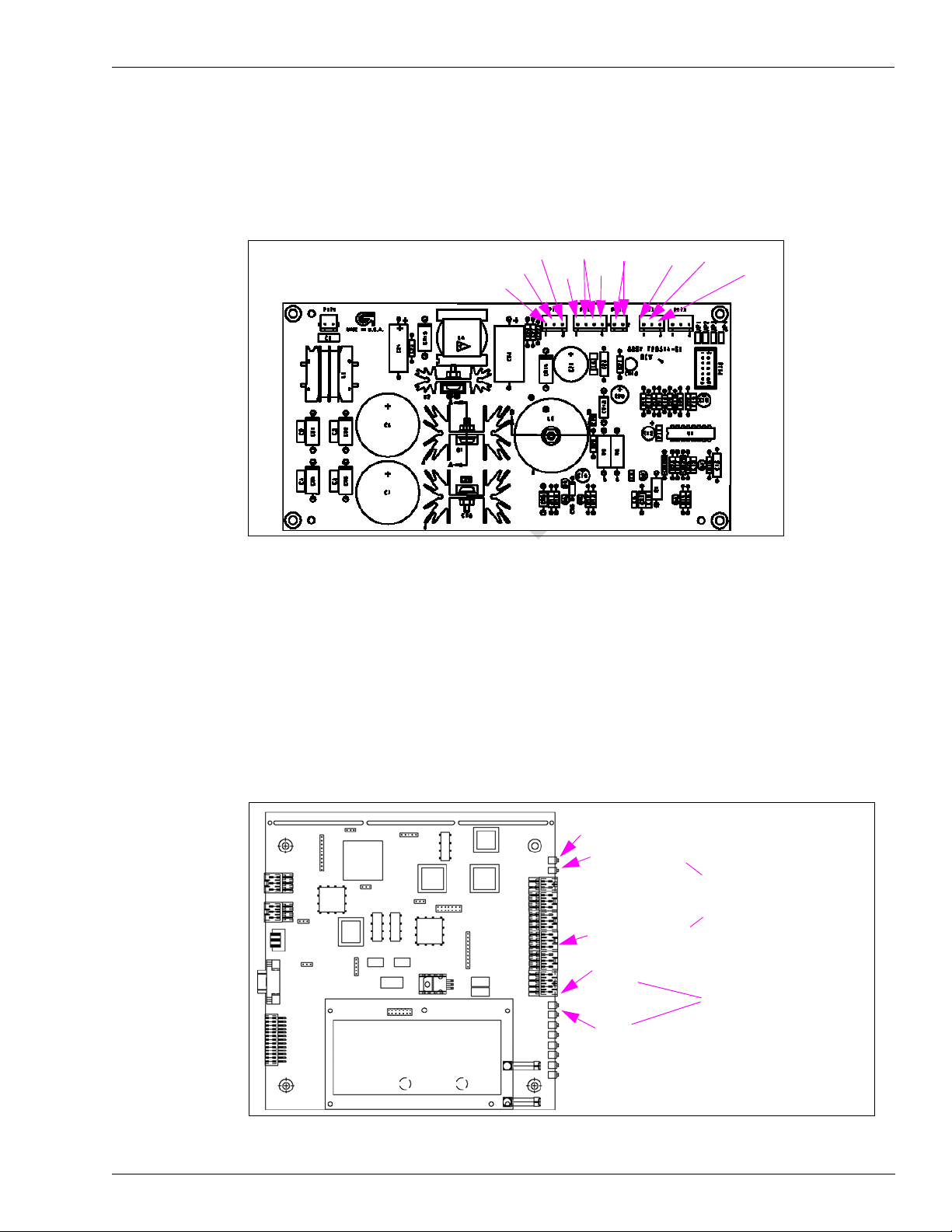
T20314 Power Supply Board.
Must be used in conjunction with R20719 transformer.
Figure 4-7: Power Supply Board T20314
Data Control Boards Q13563
Data Control Boards Q13563-01 and Q13563-02 are used in T202 29-G1 full system card cage
assembly. The Q13563-04 board is used in T20606-G2 full system card cage assembly. These
DCBs handle tag reader control and pass the system status and tag data up to the Gateway
board. The earlier versions (-01, -02) of this board made use of jump jacks on the power
supply board for dither sync addressing, subsequent versions (-04 and above) contain dip
switches for this site-specific addressing.
Preliminary
Figure 4-8: Data Control Boards Q13563-01 and Q13563-02
MDE-3664B TRIND Start-Up, Service, and Parts Manual . March 2013 Page 19
Major Hardware Components Card Cage Assemblies
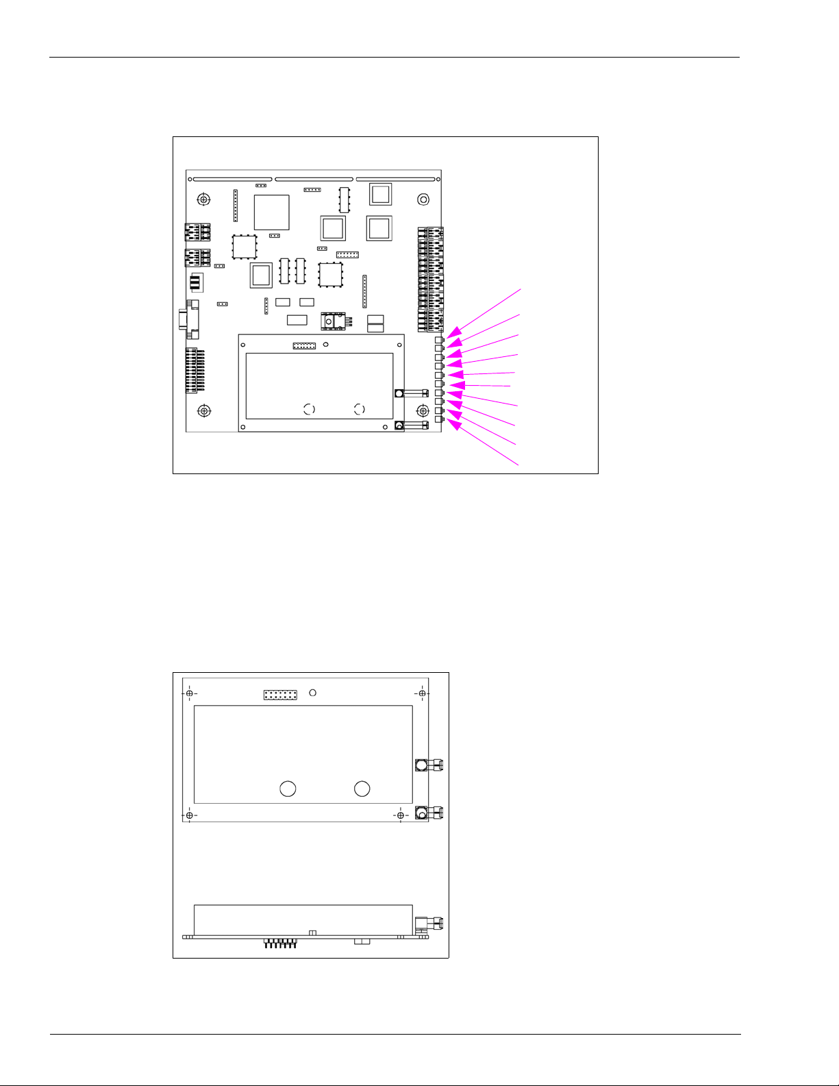
Q13563-04 and Above
Heart Beat
RS-485 TX
Read ANT 1
Read ANT 3
Bezel I/0 Error
Bit Restore
Bit Fail
RS-485 RX
+12 Vdc
+5 Vdc
Figure 4-9: Data Control Boards Q13563-03 and Above
ry
UHF Receiver Board Q13564
Mounted on the DCB, the UHF Receiver Board receives 12VDC from the DCB. The board
also receives information from UHF antennas over J2A or J2B and processes the UHF signal.
This receiver has to comply with FCC and in-country communication protocols such as ETSI.
For this application the ETSI protocol is required for Asia and Europe.
re
Figure 4-10: UHF Receiver Board Q13564
P
na
i
m
li
Page 20 MDE-3664B TRIND Start-Up, Service, and Parts Manual . March 2013
Card Cage Assemblies Major Hardware Components
The UHF Receiver Module contained on the DCB, handles the uplink signal from the vehicle
tag. It receives the signal from the vehicle tag that transmits data on a UHF carrier, and down
converts and demodulates this signal to binary data. The UHF Receiver also includes the
master oscillator for the DCB and provides all clock signals for other elements within the DCB
to keep signal paths as short as possible. The UHF receive antenna connections are made via
Sub Miniature A (SMA) connectors on antenna cables M00878A001, M00878A002, and
Q13578-01.
Transmitter Board Q13579
Transmitter Board Q13579-01 is used in the T20229-G1 and T20606-G2 full system card
cages. The Transmitter Board is actually a three board assembly containing two identical
transmitter modules (one each for Sides 1 and 2) mounted on a larger printed circuit board.
The Transmitter Module (Q13579-01) contains all the functions to activate vehicle tags. The
module includes a carrier board onto which are mounted two transmit-only Radio Frequency
Modules (RFMs), the power supply, oscillator and tuning connector for the RFMs, logic
circuitry to determine RFM selection, power level adjustment capability, and a pulse width
modulation circuit. This board receives +22VDC, +5VDC and GND through J6. If this board
is replaced, overhead antennas will need to be retuned. The transmitter provides an
approximate 134 kHz signal for TRIND antennas, through JA for Side 1 and JB for Side 2 of
the dispenser.
Figure 4-11: Transmitter Board Q13579
Preliminary
MDE-3664B TRIND Start-Up, Service, and Parts Manual . March 2013 Page 21

Major Hardware Components Card Cage Assemblies
TX = To A Side CRIND
RX = From B Side CRIND
PWR = 5V
Must match corresponding CRIND address
T20128-GX
CPU = Software Running
CPU = Software Running
PWR = 5V
RX = From A Side CRIND
TX = To A Side CRIND
RX = From B Side CRIND
TX = To B Side CRIND
TX = To A Side CRIND
T20678-GX
Gateway Boards T20128, T20678
Gateway Board T20128-GX is used in the T20229-G1 and T20606-G2 full system card cages.
The T20678 Gateway Board is used in the T20606-G3 card cage. These boards manage events
and message processing to/from the Controller (CRIND, POS, host controller) and the readers.
On the full systems, the gateway board manages RFID processing through the DCB (which
communicates with the vehicle tags via overhead antennas and with hand-held tags via bezel
readers). On Enhanced Gateway systems, the board manages hand-held RFID processing
through direct communication with the bezel readers.
Figure 4-12: Gateway Boards T20128 and T20678
ry
i
m
li
re
P
na
Page 22 MDE-3664B TRIND Start-Up, Service, and Parts Manual . March 2013

Card Cage Assemblies Major Hardware Components
Card Cage Cable Harness T20662-G2
The T20662-G2 card cage cable harness assembly provides power and data distribution to/
from the card cage and the Light/MicroReader PCA. It comes already installed on the T20606G2 card cage from the factory.
Figure 4-13: Card Cage Cable Harness T20662-G2
Full System TRIND R20520-G1 Transmitter Cable
The R20520-G1 Transmitter Cable is a 26-pin connector cable that is routed between the
Q13579 Low Frequency Transmitter Board and the Q13563 Data Control Board.
Figure 4-14: Transmitter Cable R20520-G1
Preliminary
MDE-3664B TRIND Start-Up, Service, and Parts Manual . March 2013 Page 23

Major Hardware Components Card Cage Assemblies
To Gateway Board
To Data Control Board
R20763-G1
R20763-G2
R20763-G3
Full System TRIND R20525-G1 RS-485 Communication Cable
The R20525-G1 RS-485 Communication Cable is a 4-pin and 5-pin connector cable that is
connected between the Q13563 Data Control Board and the T20128 Gateway Board.
Figure 4-15: RS-485 Communication Cable R20525
Full System TRIND R20763-GX Power Supply Cables
The R20763-GX Power Supply Cables connect the LF Transmitter (-G1), the DCB (-G2) and
the Gateway(-G3) boards to the T20314 power supply.
ry
Figure 4-16: Power Supply Cables
m
li
re
P
na
i
Page 24 MDE-3664B TRIND Start-Up, Service, and Parts Manual . March 2013

Card Cage Assemblies Major Hardware Components
Hand-Held TRIND System M00507 Ribbon Cable
The M00507 Ribbon Cable is a 14-pin cable routed between T12678 Gateway Board and the
R20773 TRIND Option Door Data and Power Cable. The R20773 cable leads to the T20601
Light/Microreader Board. The -A001 cable is used for Side A (or Side 1 based on the
dispenser). The -A002 cable is used for Side B (or Side 2 based on the dispens er).
Figure 4-17: Hand-Held TRIND System Ribbon Cable M00507
Hand-Held TRIND System M01366 Power Cable
The M01366 TRIND Power Cable is a 3-wire cable routed between the T20314 Power Supply
Assembly and the T20678 Gateway Board.
Figure 4-18: Hand-Held TRIND System Power Cable M01366
Preliminary
MDE-3664B TRIND Start-Up, Service, and Parts Manual . March 2013 Page 25

Major Hardware Components TRIND Overhead Antennas
5
6
4
3
1, 2
TRIND Overhead Antennas
Full System TRIND has six antennas, four active and two passive. The active antennas can
further be divided as transmit only (overhead antennas) and transmit and receive (option door/
CIM door antennas). All four operate in the Low Frequency (LF) band at 134.2 kHz. The two
passive antennas receive in the UHF Band at 902 MHz (in the US) and at 868 MHz (Asia &
Europe) and are used in conjunction with the overhead antennas to utilize the car tags. There
are two basic variations of the full system TRIND. The fundamental differences are based on
the card cage and the overhead antennas used. The antennas can be divided into two sections,
the original Mobil antennas (no longer available) and the single-loop antennas, which are
currently being shipped with full system TRIND.
T20231 Mobil Overhead Antenna Assembly
The Mobil overhead antenna assembly consists of a multiple loop (47 uH) coil for LF
transmission, a tuning board, and sheet metal slot antenna for UHF receive. This assembly is
no longer available, but is still a part of the installed base at Mobil Stations. These antennas
have been replaced by T20632 family of overhead antennas.
ry
Figure 4-19: Mobil Overhead Antenna Assembly T20231
na
i
m
li
re
P
T20231 Mobil Overhead Antenna Assembly Parts List
Item Description Part Number
1 902.858 MHz high frequency antenna Q13580-01
2 868.4 MHz High Frequency Antenna Q13580-02
3 Molded Antenna Q13582-01
4 Tuning Board Q13582-02
5 Tuner Gasket Q13582-04
6 Tuner Cover Q13582-03
Page 26 MDE-3664B TRIND Start-Up, Service, and Parts Manual . March 2013

TRIND Overhead Antennas Major Hardware Components
1
2
10
9
8
7
6
5
4
3
Note: For units with Logo
Display Cabinets
universal antenna
brackets are
installed with flat
side up.
Figure 4-20: T20231 Mobil Overhead Antenna Bracket Assemblies and Hardware
Preliminary
MDE-3664B TRIND Start-Up, Service, and Parts Manual . March 2013 Page 27

Major Hardware Components TRIND Overhead Antennas
T20231 Mobil Overhead Antenna Bracket Assemblies and Hardware for The Advantage Series
Item Description
1 antenna top cover T20213-01 T20213-01 T20215-01 T20215-01
2 bracket, universal antenna T20212-01 T20212-01 T20212-01 T20212-01
3 bracket, antenna mounting T20211-01 T20211-01 T20211-01 T20211-01
3a bracket, antenna mounting (note 1) T20211-02 - T20211-02 4 screw, 10-32 black K85736-45 K85736-45 K85736-45 K85736-45
5 antenna assembly T20231-G1 T20231-G1 T20231-G1 T20231-G1
6 1/4-20 bolt x 4" black K01914-70 K01914-70 K01914-70 K01914-70
7 1/4-20 nut, black Q11890-08 Q11890-08 Q11890-08 Q11890-08
8 over head antenna cables R20509-G1
9 connector, tube fitting Q13591-01 Q13591-01 Q13591-01 Q13591-01
10 conduit, flexible black plastic Q13592-02 Q13592-02 Q13592-02 Q13592-02
Notes:
1. Not shown on page 28, single-sided antenna bracket has no antenna mounting arms.
Wide Frame
Single-Sid
Q13578-
ed
01
Wide Frame
Double-Sided
R20509-G1
Q13578-01
ry
Narrow Frame
Single-Sided
R20509-
G1
Q13578-01
Narrow Frame
Double Sided
R20509-G1
Q13578-01
na
T20231 Mobil Overhead Antenna Bracket Assemblies and Hardware for the MPD-3
Item Description
1 antenna top cover T20214-01 T20214-01 T20214-01 T20214-01
2 bracket, universal antenna T20212-01 T20212-01 T20212-01 T20212-01
3 bracket, antenna mounting T20211-01 T20211-01 T20211-01 T20211-01
3a bracket, antenna mounting (note 1) T20211-02 - T20211-02 4 screw, 10-32 black K85736-45 K85736-45 K85736-45 K85736-45
5 antenna assembly T20231-G1 T20231-G1 T20231-G1 T20231-G1
6 1/4-20 bolt x 4" black K01914-70 K01914-70 K01914-70 K01914- 70
7 1/4-20 nut, black
8 over head antenna cables R20509-G1
9 connector, tube fitting Q13591-01 Q13591-01 Q13591-01 Q13591-01
10 conduit, flexible black plastic Q13592-02 Q13592-02 Q13592-02 Q13592-02
Notes:
1. Not shown on page 28, single-sided antenna bracket has no antenna mounting arms.
re
P
m
li
i
PMI Bezel
Single-Sided
Q11890-08 Q11890-08 Q11890-08 Q11890-08
Q13578-01
PMI Bezel
Double-Sided
R20509-G1
Q13578-01
Mack Bezel
Single-Sided
20509-G1
R
Q13578-01
Mack Bezel
Double Sided
R20509-G1
Q13578-01
Page 28 MDE-3664B TRIND Start-Up, Service, and Parts Manual . March 2013

TRIND Overhead Antennas Major Hardware Components
Sub Miniature A (SMA) connections should be treated with care and not overtightened.
The maximum torque rating on these connectors is usually measured in inch pounds
Too severe a turn or bend in the cable may damage the center conductor or compro mise the
shield/drain portion of the cable.
This can result in an observance of intermittent reads or other problems. The poor
performance will in turn generate a premature field service call . Replacing this cable is
labor intensive after the system is installed the first time.
Turns or bends in coaxial cable must be gradual loops, no sharper than a 1-inch radius (2inch diameter).
CAUTION
CAUTION
It is critical that the proper tool is used when tuning the overhead antennas on TRIND
systems. Only the Q13631-02 (part of ASC Tool Kit K94577-01 ) plastic tuning tool (or
similar plastic 0.10in. hex tool) should be used for tuning overhead antennas.
Using a metal screwdriver or Allen wrench has two negative effects. First, a proper tuning
is impossible as the metal of the tool used changes the properties of the variable inductor
used for tuning. Second, the ferrite slug used in the variable inductor is extremely brittle
and is broken or stripped easily by metal tools, preventing the proper tuning of the antenna.
If the antenna is not properly tuned the read range can be significantly reduced
T20632 Single-Loop Overhead Antenna Assembly
The T20632-GX Single-Loop Overhead Antenna Assemblies are made up from a single turn
(loop) antenna; a high efficiency tuning board, and a UHF receive antenna. These parts are all
mounted in a molded polycarbonate set of boxes and then mounted wi th brackets on top of the
dispenser. These parts are discussed in further in the following sections.
Preliminary
MDE-3664B TRIND Start-Up, Service, and Parts Manual . March 2013 Page 29
Note: There are eight different “G” levels of this antenna assembly, due to the differe
and heights of the dispensers.
T20632 “G” Level Dispenser Antenna is used on
G1/G5 Advantage Wide Frame and MPD-3
G2/G6 Advantage Narrow Frame
G3/G7 Encore
G4/G8 Advantage Wide Frame With Exxon Light Box
nt widths

Major Hardware Components TRIND Overhead Antennas
8
4
3
2
1
6
5
11
7
10
9
Figure 4-21: T20632 Single-Loop Overhead Antenna Assembly
ry
na
i
m
li
T20632 Single-Loop Overhead Antenna Assembly Parts List (Domestic)
re
P
Item Description T20632-G1 T20632-G2 T20632-G3 T20632-G4
1 Bottom Right Antenna Box T20615-04 T20615-04 T20615-04 T20615-04
2 Top Right Antenna Box T20615-02 T20615-02 T20615-02 T20615-02
3 Antenna W03889-01 W03889-02 W03889-03 W03889-04
4 Bottom Left Antenna Box T20615-03 T20615-03 T20615-03 T20615-03
5 Screw Thread Form #6-19 Q12011-17 Q12011-17 Q12011-17 Q12011-17
6 Antenna Tuner PCA T20579-G1 T20579-G2 T20579-G3 T20579-G4
7 Lock Washer K46212 K46212 K46212 K46212
8 Top Left Antenna Box T20615-01 T20615-01 T20615-01 T20615-01
9 Hex Nut Q11890-04 Q11890-04 Q11890-04 Q11890-04
10 UHF Receiver Antenna Q13851-01 Q13851-01 Q13851-01 Q13851-01
11 Neoprene Adhesive Tape Q11899-12 Q11899-12 Q11899-12 Q11899-12
Page 30 MDE-3664B TRIND Start-Up, Service, and Parts Manual . March 2013

TRIND Overhead Antennas Major Hardware Components
1
3
5
6
6
4
6
5
6
2
3
T20632 Single-Loop Overhead Antenna Assembly Parts List
(International)
Item Description T20632-G5 T20632-G6 T20632-G7 T20632-G8
1 Bottom Right Antenna Box T20615-04 T20615-04 T20615-04 T20615-04
2 Top Right Antenna Box T20615-02 T20615-02 T20615-02 T20615-02
3 Antenna W03889-01 W03889-02 W03889-03 W03889-04
4 Bottom Left Antenna Box T20615-03 T20615-03 T20615-03 T20615-03
5 Screw Thread Form #6-19 Q12011-17 Q12011-17 Q12011-17 Q12011-17
6 Antenna Tuner PCA T20579-G1 T20579-G2 T20579-G3 T20579-G4
7 Lock Washer K46212 K46212 K46212 K46212
8 Top Left Antenna Box T20615-01 T20615-01 T20615-01 T20615-01
9 Hex Nut Q11890-04 Q11890-04 Q11890-04 Q11890-04
10 UHF Receiver Antenna Q13851-02 Q13851-02 Q13851-02 Q13851-02
11 Neoprene Adhesive Tape Q11899-12 Q11899-12 Q11899-12 Q11899-12
Figure 4-22: T20632 Single Loop Antenna Brackets and Hardware
Preliminary
MDE-3664B TRIND Start-Up, Service, and Parts Manual . March 2013 Page 31

Major Hardware Components TRIND Overhead Antennas
T20632 Single Loop Antenna Assembly Bracket Kits for The Advantage
Series
W/F & N/F RID
Plus Exx
Item Description
1 Antenna Bracket, Left T20623-01 T20624-01 - 2 Antenna Bracket, Right T20623-02 T20624-02 - 1 Antenna Bracket, W/F & N/F - - T20625-01 2 Antenna Bracket, W/F & N/F - - T20625-02 1 Antenna Bracket, ADV & MPD-3 - - - T20628-01
2 Antenna Bracket, ADV & MPD-3 - - - T20628-02
3 Gasket, Mounting Bracket N23958-01 N23958-01 N23958-01 N23958-01
4 Gasket, Antenna Wire Bracket N23959-01 N23959-01 N23959-01 N23959-01
5 Screw, Hex Head Q11889-104 Q11889-104 Q11889-104 Q11889-104
6 Fastener, Self-Drilling - - - Q13897-01
(K96647-01)
on
With Canopy
(K96647-02)
With Or
Out Blue Ha
With
(K96647-03)
With Milwaukee
ts
Light Box
(K96647-06)
ry
T20632 Single Loop Antenna Assembly Bracket Kits for the MPD-3
Series
na
i
Item Description
1 Antenna Bracket, Left T20626-01 T20627-01 2 Antenna Bracket, Right T20626-02 T20627-02 1 Antenna Bracket, ADV & MPD-3 - - T20628-01
2 Antenna Bracket, ADV & MPD-3 - - T20628-02
3 Gasket, Mounting Bracket N23958-01 N23958-01 N23958-01
4 Gasket, Antenna Wire Bracket N23959-01 N23959-01 N23959-01
6 Screw, Hex Head Q11889-104 Q11889-104 Q11889-104
6 Fastener, Self-Drilling - - Q13897-01
re
P
li
With Canopy
(K96647--04)
m
With Ou
(K
Canopy
96647-05)
t
With Milwaukee
(K96647-06)
Light Box
T20632 Single Loop Antenna Assembly Bracket Kit for the Encore Unit
Item Description K96647--07
1 Antenna Bracket, Encore T20630-01
2 Antenna Bracket, Encore T20630-02
3 Gasket, Bracket Mounting N23958-01
4 Gasket, Antenna Wire Bracket N23959-01
5 Screw, Hex Head Q11889-104
Page 32 MDE-3664B TRIND Start-Up, Service, and Parts Manual . March 2013

TRIND Overhead Antennas Major Hardware Components
Ultra High Frequency Antenna Q13851-01 and Q13851-02
This antenna is specifically used to receive the UHF response from the vehicle mount tag. It
has a “pigtail” RG-316 coaxial cable with a Sub Miniature A (SMA) jack on the other end
connected to it for ease of manufacture and installation purposes. Q13851-01 is intended for
domestic use and is found in the T20632-G1 through T20632-G4 Single Loop Antenna
Assemblies. Q13851-02 is intended for international use and is found in the T20632-G5
through T20632-G8 Single Loop Antenna Assemblies.
Antenna Tuning Board T20579-GX
The Antenna Tuning Board (T20579-GX) allows the resonance tuning of the low frequency
downlink antenna to match with the Transmitter Module to compensate for product tolerances
at manufacturing, and to achieve the maximum field strength. The antenna circuit is tuned to
resonance by adjusting the ferrite core of the on-board coil with a 0.10-inch hex tuning tool
located in K94577-01 ASC TRIND Tool Kit.
Important: The “G”
Capacitance values are different between the boards due to the different sizes of the single
loop antenna itself.
level of this board must match the “G” level of the final assembly.
Preliminary
MDE-3664B TRIND Start-Up, Service, and Parts Manual . March 2013 Page 33

Major Hardware Components TRIND Option Doors With Antennas
TRIND Option Doors With Antennas
This section provides descriptions and parts information for TRIND options contained in the
doors of the Advantage, MDP-3, Encore and Eclipse dispensers. This version of TRIND
consists of RFID components, including the antenna, mounted on the door. The antennas used
for the option doors on the Advantage and the Encore/Eclipse, perform transmit and receive
functions and interact directly with a microreader that’s contained on a light board located in
the door. The inducti ve antennas utilize the magnetic near field (air interface) generated by the
microreader to interact with the hand-held tags.
The T20601-G1/G2 Light MicroReader PCA is used on the Advantage and MPD-3
dispensers. The T20601-G1 board has red LEDs, the T20601-G2 board has orange LED's. The
LEDs light to provide an indication to the consumer that the key tag has been read. In addition,
the board processes data received from the key tag antenna, and sends the processed data to the
DCB or Enhanced Gateway board.
The Key-Tag Antenna (T20524-G1) is used on Advantage and MPD-3 dispensers. It connects
to the T20601-GX PCA, and is used as an antenna for the key tag portion of the system. An
R20522-G2 cable provides a connection between the T20524 and T20601 PCAs.
The M01218A001/A002 Light MicroReader/Antenna PCA is used on the Encore/Eclipse
dispensers. The M01218A001 board has red LEDs, M01218A002 board has orange LED's.
The board provides indication to the consumer that the tag has been read. In addition, the
board processes data received from the key tag antenna, and sends the process data to the DCB
or Enhanced Gateway board. The antenna for key-tag portion of the system has been
integrated into this assembly. This board also has the ability to be re-configured from red to
orange LEDs, and vice-versa, in the field.
m
li
na
i
ry
re
P
Page 34 MDE-3664B TRIND Start-Up, Service, and Parts Manual . March 2013

TRIND Option Doors With Antennas Major Hardware Components
7
5
10
11
6
4
3
1
8
9
2
MPD-3 Bezel Assemblies
The following sections provides parts information for the MPD-3 Bezel Assemblies.
Figure 4-23: T20616-G1 MPD-3 Bezel Assembly
T20616-G1 MPD-3 Bezel Assembly Parts List
Item Description Part Number
1 Housing, MPD-3 T20417-G1
2 Tape, Single Coated Neoprene Sponge Q11899-02
3 TI/RFID Antenna Assembly T20524-G1
4 Light Micro Reader PCA T20601-G1
5 Inside Cover Gasket R20584-01
6 Inside Cover, MPD-3 Housing T20216-01
7 Bezel Panel Assembly T17446-G8
8 Interface Hand Held Antenna Cable R20522-G2
9 TRIND Option Door Data and Power Cable R20773-G2
10 Cable Access Gasket N23881-01
11 Plate, Lock N23873-G1
Preliminary
MDE-3664B TRIND Start-Up, Service, and Parts Manual . March 2013 Page 35

Major Hardware Components TRIND Option Doors With Antennas
7
5
10
6
4
3
1
8
9
2
11
13
12
14
Figure 4-24: T20616-G2 MPD-3 Bezel Assembly
ry
na
i
T20616-G2 MPD-3 Bezel Assembly Parts List
Item Description Part Number
1 Housing, MPD-3 T20179-01
2 Tape, Single Coated Neoprene Sponge Q11899-02
3 TI/RFID Antenna Assembly T20524-G1
4 Light Micro Reader PCA T20601-G1
5 Inside Cover Gasket R20584-01
6 Inside Cover, MPD-3 Housing T20216-01
7 Bezel Panel Assembly (Note 1) T17534-G05
8 Interface Hand Held Antenna Cable R20522-G2
9 TRIND Option Door Data and Power Cable R20773-G2
10 Cable Access Gasket N23881-01
11 Spacer, Split (Note 2) K87404-01
12 Gasket, 0.88 O.D. (Note 2) Q11659-01
13 Washer (Note 2) N16599-78
14 Nut, Self Locking Hex (Note 2) Q10218-01
Notes:
1. Bolt-On Panel for Mack Bezels.
2. Bezel Assembly requires a quantity of six (6).
re
P
m
li
Page 36 MDE-3664B TRIND Start-Up, Service, and Parts Manual . March 2013

TRIND Option Doors With Antennas Major Hardware Components
6
1
2
5
4
3
9
7
14
11
12
15
13
8
10
16
Figure 4-25: T20251-G1 MPD-3 Bezel Assembly
T20251-G1 MPD-3 Bezel Assembly Parts List
Item Description Part Number
1 housing, MPD-3 T20179-01
2 tape, single coated neoprene sponge Q11899-02
3 o-ring, 4.25 x 4.28 Q13575-02
4 lens, Mobil Q13575-01
5 diffuser Q13575-03
6 bracket, lens retainer Q13575-04
7 TI/RFID Antenna PCB assembly T20143-G1
8 TI/RFID Light/Microreader PCB T20446-G1
9 gasket, inside cover R20584-01
10 inside cover, MPD-3 housing T20216-01
11 bezel panel assembly T17446-G8 (note 1)
12 gasket, cable access N23881-01
13 plate, lock N23873-G1
14 cable, hand held antenna interface R20522-G1
15 cable, light microreader R20519-G3
16 interface/microreader, cable R20521-G3
Notes:
1. Slide-in panel for PMI bezels.
Preliminary
MDE-3664B TRIND Start-Up, Service, and Parts Manual . March 2013 Page 37

Major Hardware Components TRIND Option Doors With Antennas
1
9
8
7
6
5
4
2
3
10
Advantage Wide Frame Option Door Assemblies
This section provides parts data for the Advantage Wide Frame Option Doors. Assemblies.
Figure 4-26: T20228-G1 Advantage Wide Frame (48-Inches) Option Door Assembly
ry
na
i
m
li
re
P
T20228-G1 Advantage Wide Frame Option Door Assembly Parts List
Item Description Part Number
1 TI/RFID Door Antenna T20143-G1
2 Light microreader PCB (note1) T20446-G1
3 antenna shield T20210-01
4 lens retainer bracket Q13575-04
5 diffuser, Wayne Q13575-03
6 logo lens Q13575-01
7 O-ring Q13575-02
8 door gasket R20424-01
9 option door, right T17499-06
10 Antenna Interface Cable R20522-G1
Notes:
1. Replaced T20182-G1 and T20295-G1
Page 38 MDE-3664B TRIND Start-Up, Service, and Parts Manual . March 2013

TRIND Option Doors With Antennas Major Hardware Components
6
5
4
3
1
2
Figure 4-27: T20613 Advantage W ide Frame (48-Inches) Option Door Assembly
T20613 Advantage Wide Frame Option Door Assembly Parts List
Item Description Part Number
1 Wide Frame Shield T20570-G1
2 Solid Strip Grommet Q10315-06
3 RFID Light/ Microreader PCA (note 1) M01580A00X
4 TRIND Antenna PCB T20524-G1
5 Door Gasket R20424-01
6 Right Option Door (note 2) T20415-0X
Notes:
1. Order entry item available as -A001 and -A002
2. Order entry item available as -01 through -08.
Preliminary
MDE-3664B TRIND Start-Up, Service, and Parts Manual . March 2013 Page 39

Major Hardware Components TRIND Option Doors With Antennas
6
7
5
2
4
3
1
8
Advantage Narrow Frame Option Door Assemblies
This section provides parts data for the Advantage Narrow Frame Option Doors.
Figure 4-28: T20614 Advantage Narrow Frame (36-Inches) Option Door Assembly
ry
na
i
m
li
re
P
T20614 Narrow Frame Option Door Assembly Parts List
Item Description Part Number
1 Solid Strip Grommet Q10315-06
2 N/F Door Shield T20571-G1
3 RFID Light/Micro Reader (note 1) M01580A00X
4 TRIND Antenna Assembly PCB T20524-G1
5 Display PCB Assembly T20262-G1
6 Access Door Gasket R20424-01
7 N/F Option Door T20416-01
Notes:
1. Order entry item available as -A001 and -A002
Page 40 MDE-3664B TRIND Start-Up, Service, and Parts Manual . March 2013

TRIND Option Doors With Antennas Major Hardware Components
2
1
3
4
5
6
7
9
10
11
12
13
8
14
Figure 4-29: T20253-G1 Advantage Narrow Frame (36-Inches) Option Door Assembly
T20253-G1 Narrow Frame Option Door Assembly Parts List
Item Description Part Number
1 N/F Option Door (note 1) T20125-0X
2 O-ring Q13575-02
3 Mobil lens Q13575-01
4 Diffuser Q13575-03
5 Lens Retainer Bracket Q13575-04
6 TI/RFID Light/Microreader PCB (note 2) T20446-G1
7 antenna shield T20210-02
8 Cable, Hand Held Interface R20522-G1
9 Display PCB Assembly T20262-G1
10 TI/RFID Antenna PCB T20143-G1
11 Display Lens Mounting Bracket R20586-01
12 Display Lens R20585-01
13 Display Lens Gasket N23879-01
14 Access Door Gasket R20424-01
Notes:
1. Order entry item available as -01 and -02.
2. Replaced T20295-G1.
Preliminary
MDE-3664B TRIND Start-Up, Service, and Parts Manual . March 2013 Page 41

Major Hardware Components TRIND Option Doors With Antennas
6
5
4
3
2
1
Encore CIM Door Option Assembly
This section provides the parts for the Encore CIM Door Option Assembly.
Figure 4-30:
Encore CIM Door Option Assembly
ry
na
i
m
li
re
P
Encore CIM Door Option Assembly Parts List
Item Description Part Number
1 Screw, Hex Head 6-20 Q11677-24
2 TRIND Light and Indicator Assembly M01218A00X (note 1)
3 CIM Door with CRIND Assembly M01208A001
4 TRIND Panel Gasket M01160B001
5 TRIND Display Window Lens M01234B001
6 Screw, Phillips M00419B117
Notes:
1. Order entry item available as red (-A001) or orange (-A002).
Page 42 MDE-3664B TRIND Start-Up, Service, and Parts Manual . March 2013

TRIND Option Doors With Antennas Major Hardware Components
1
2
3
4
5
Eclipse Ovendoor Option Assembly
This section provides the parts for the Eclipse Ovendoor Option Assembly.
Figure 4-31:
Eclipse Ovendoor Option Assembly
Eclipse Ovendoor Option Assembly Parts List
Item Description Part Number
1 Eclipse TRIND/Cash Acceptor Ovendoor M01509A001
2 Eclipse Ovendoor TRIND Assembly M01661A001
3 TRIND PCB Cover M01408B001
4 Slotted 6-20X.3125 Screw Q11677-23
5 TRIND Light and Indicator Assembly M01218A00X (note 1)
Notes:
1. Order entry item available as red (-A001) or orange (-A002).
Preliminary
MDE-3664B TRIND Start-Up, Service, and Parts Manual . March 2013 Page 43

Major Hardware Components TRIND Option Doors With Antennas
Note: Used With
Card Cage T20229
In Kit C00011-001.
Note: Used With Card Cage
T20606-GX In Kits C00011002 And Above.
Light/Microreader PCB T20446-G1, T20601-GX, M01580A001, and M01580A002
Note: T20446 replaced Light/Microreader PCB T20182-G1 and T20295-G1. M01580A001
and M01580A002 replaced Light/Microreader PCB T20601-G1 and G2
The PCB is mounted on the right options door on The Advantage Series units or in an
enclosure
hand-held transponder and provides tag read indicator lights for the TRIND system. The PCB
requires both 5VDC and 22.5VDC supplied at plug P182. The PCB also provides hand-held
transmitter information to the DCB or Enhanced Gateway board. In addition, the PCB receives
information regarding light control from the DCB. These activities are also done through plug
P182.
Figure 4-32: Light/Microreader Printed Circuit Board T20446-G1
mounted on the bezel for MPD
-
3 units. The PCB processes data received from the
ry
na
i
m
li
re
Figure 4-33: Light/Microreader Printed Circuit Board T20601-G1
P
Page 44 MDE-3664B TRIND Start-Up, Service, and Parts Manual . March 2013

TRIND Option Doors With Antennas Major Hardware Components
Note: Used With Card
Cage T20606-GX In
Kits C00011-002 And
Above.
Figure 4-34: Light/Microreader Printed Circuit Board M01580A00X
Light/Microreader PCB M01218A001 and M01218A002
Mounted on the CIM Door on Encore and Eclipse units, this PCB processes information
received from hand-held transponder (only), as well as provide indicator lights for the TRIND
system. The PCB requires both 5VDC and 22.5VDC supplied at P182. The PCB provides
transmitter activity data to the DCB, and receives light control information from the DCB.
These activities are done through P182. The antenna is integrated into this assembly.
Figure 4-35: Light/Microreader Printed Circuit Board M01218A00X
Preliminary
MDE-3664B TRIND Start-Up, Service, and Parts Manual . March 2013 Page 45

Major Hardware Components TRIND Option Doors With Antennas
Hand-Held Antenna PCB T20143-G1
Hand-Held PCB T20143-G1 is used on the original system and is connected to Light/
Microreader PCB (i.e. T20182) at P181 and mounted on options or bezels doors.
Figure 4-36: Hand Held Antenna Printed Circuit Board T20143-G1
ry
TRIND Antenna PCA T20524-G1
The T20524-G1 PCAs are 47uH antennas that work with the Microreader. They are energized
by the Microreader at 132 kHz to generate the exciter frequency of 134.2 kHz.
re
P
Figure 4-37: TRIND Antenna PCA T20524-G1
na
i
m
li
Page 46 MDE-3664B TRIND Start-Up, Service, and Parts Manual . March 2013

System Cables Major Hardware Components
M00878A001
M00878A002
To DCB or Enhanced
Gateway Board
To TRIND Light Board
System Cables
This section provides a description and parts information for the TRIND system cables. These
cables are used to make connections between the various TRIND and dispenser components
that comprise the TRIND system.
M00878 Low/High Frequency Antenna Cable
The overhead antenna cable assemblies M00878A001 and M00878A002, connect the
overhead antennas to the TRIND UHF receiver and LF transmitter. The M00878A001 cable is
used for the Encore units, the M00878A002 is used for the Advantage and MPD-3 units.
Note: If the unit has an Exxon Lightbox,
(M01380A001) used for this configuration.
there is an overhead antenna cable extensio n
Figure 4-38:
Low/High Frequency Antenna Cable
Preliminary
R20773 Power and Data Option Door Cable
The R20773 cable is a power and data option door cable that connects the Light/Micro-Reader
PCA to the TRIND card cage.
Note: This cable exists in some quantities as 55 inches long. This was eventually
70 inches long (Revision C and above). If you encounter the shorter version, you will
need an extender cable (M01557A001) for each side of the dispenser.
changed to
MDE-3664B TRIND Start-Up, Service, and Parts Manual . March 2013 Page 47
Figure 4-39: Power and Data Option Door Cable R20773

Major Hardware Components System Cables
R20437-G01 TRIND to CRIND Logic Cable (Advantage and MPD-3)
The R20437-G01 TRIND to CRIND Logic Cable connects the TRIND Gateway Broads
(T20128 and T20678) to CRIND Logic boards.
Figure 4-40: TRIND to CRIND Logic Cable R20437
ry
na
i
m
li
M00515A002 TRIND to CRIND Logic Cable For Encore 500 and Eclipse
The M00515A002 TRIND to CRIND Logic Cable for Encore 500 and Eclipse connects the
Gateway Boards to the CRIND Logic Boards.
Figure 4-41: TRIND to CRIND Logic Cable M00515A002
re
P
Page 48 MDE-3664B TRIND Start-Up, Service, and Parts Manual . March 2013

System Cables Major Hardware Components
R20580
M00811A001
M001804A001 TRIND to CRIND Logic Cable for Encore 300
The M001804A001 TRIND to CRIND Logic Cable for Encore 300 connec ts the Gateway
Boards to the CRIND Logic Boards.
Figure 4-42: TRIND to CRIND Logic Cable M001804A001
R20580 and M00811A001 AC Power Cables
The R20580 and M00811A001 AC Power Cables are used to provide system power to the
TRIND card cage assembly. Connections for these cables are unit specific. Use appropriate
connector to intercept power on existing unit power cable.
Figure 4-43: AC Power Cables
Preliminary
MDE-3664B TRIND Start-Up, Service, and Parts Manual . March 2013 Page 49

Major Hardware Components System Cables
Full System Cable Connections on the Legacy Advantage Series Dispensers
For all single-sided units, dummy load R20526-01 is installed on JB on transmitter PCB and
eliminates all ‘B’ side connections.
Note: If power is applied to card cage without the an
the transmitter board will be damaged.
On Cable Connect To On
R20509-G2 (marked for ‘A’ side) P1/2 J1 Side A overhead antenna (low frequency)
PA/B *JA Transmitter PCB Q13564
R20509-G2 (‘B’ side, unmarked) P1/2 J2 Side B overhead antenna (low frequency)
PA/B *JB Transmitter PCB Q13564
R20519-G1 J182 P182 Light/microreader PCB assembly T20182 on ‘A’ side options door
P7 *J7 DCB PCB Q13563
R20519-G2 J182 P182 Light/microreader PCB assembly T20182 on Side B options door
P8 *J8 DCB PCB Q13563
R20521-G1 J180 P180 Light/microreader PCB assembly T20182 on Side A options door
J177 *P177 Power supply PCB T20138
GRD *Ground stud Card cage
R20521-G2 J180 P180 Light/microreader PCB assembly T20182 on Side B options door
J176 *P176 Power supply PCB T20138
GRD *Ground stud Card cage
Q13578-01 -01 (marked for ‘A’ side) P1 J1 Side A side overhead antenna (high frequency)
P1 *J2B Receive PCB
Q13578-01 (‘B’ side, unmarked) P1 J2 Side B overhead antenna (high frequency)
P1 *J2A Receive PCB
R20437-G01 J250 *P250 TI Gateway PCB T20128-G1
J258A P258 Side A CRIND logic PCB T17764
J258B P258 Side B CRIND logic PCB T17764
R20580-G1(per unit) 3 prong F 3 prong M Card cage, rear
re
P
m
li
na
i
tenna cables or dummy load connected,
ry
Note: Asterisk (*) indicates connection point is on card cage assembly.
Note: Route cables R20521-G1 and -G2 and R20437-G01 through bottom of card cage to ‘B’
side for connecti
Note: Check whether brand panel lighting ballast is connected to powe
disconnect ballast from power supply and terminate wires ends according to NFPA 70,
the National Electric Code and applicable local codes.
Page 50 MDE-3664B TRIND Start-Up, Service, and Parts Manual . March 2013
ons.
r supply. If so,

System Cables Major Hardware Components
Full System Cable Connections on the MPD-3 Dispensers
For all single-sided units, install dummy load connector R20526-01 on JB on transmitter PCB
and skip all ‘B’ side connections.
Note: If power is applied to card cage without the antenna cables or dummy load connected,
the transmitter board will
On Cable Connect To On
R20509-G2 (marked for ‘A’ side) P1/2 J1 ‘A’ side overhead antenna (low freq)
PA/B *JA Transmitter PCB Q13564
R20509-G2 (‘B’ side, unmarked) P1/2 J2 ‘B’ side overhear antenna (low freq)
PA/B *JB Transmitter PCB Q13564
R20519-G3 (marked for ‘A’ side) J182 P182 Light/microreader PCB assembly T20182 on ‘A’ side faceplate assembly
P7 *J7 DCB PCB Q13563
R20519-G3 (‘B’ side, unmarked) J182 P182 Light/microreader PCB assembly T20182 on ‘B’ side faceplate assembly
P8 *J8 DCB PCB Q13563
R20521-G3 (marked for ‘A’ side) J180 P180 Light/microreader PCB assembly T20182 on ‘A’ side faceplate assembly
J177 *P177 Power supply PCB T20138
GRD *Ground stud Card cage
R20521-G3 (‘B’ side, unmarked) J180 P180 Light/microreader PCB assembly T20182 on ‘B’ side faceplate assembly
J176 *P176 Power supply PCB T20138
GRD *Ground stud Card cage
Q13578-01 -01 (marked for ‘A’ side) P1 J1 ‘A’ side overhead antenna (high freq)
P1 *J2B Receive PCB
Q13578-01 (‘B’ side, unmarked) P1 J2 ‘B’ side overhead antenna (high freq)
P1 *J2A Receive PCB
R20437-G01 J250 *P250 TI Gateway PCB T20128-G1
J258A P258 ‘A’ side CRIND logic PCB T17764
Preliminary
J258B P258 ‘B’ side CRIND logic PCB T17764
R20580-G1 P601
J601
3 prong F 3 prong M Card cage, rear
be damaged.
Note: Asterisk(*) indicates connection point is on card cage assembly.
MDE-3664B TRIND Start-Up, Service, and Parts Manual . March 2013 Page 51

Major Hardware Components System Cables
Full System Cable Connections on The Advantage Series and MPD-3 Dispensers
For all single-sided units, dummy load connector R20526-01 is installed on JB on transmitter
PCB and eliminates all ‘B’ side connections.
Note: If power is applied to card cage without antenna cables or dummy load connected
transmitter board will be damaged.
On Cable Connect To On
M00878A002 PA JA Transmitter PCB Q13579-01
PB JB Transmitter PCB Q13579-01
P1A J1 Side A Low Frequency Overhead Antenna
P1B J1 Side B Low Frequency Overhead Antenna
P2A J2A UHF Receive PCB Q13564
P2B J2B UHF Receive PCB Q13564
P3A J2 Side A High Frequency Overhead Antenna
P3B J2 Side B High Frequency Overhead Antenna
R20509-G2 (marked for ‘A’ side) P1/2 J1 Side A overhead antenna (low frequency)
PA/B *JA Transmitter PCB Q13564
R20509-G2 (‘B’ side, unmarked) P1/2 J2 Side B overhead antenna (low frequency)
PA/B *JB Transmitter PCB Q13564
R20519-G1 J182 P182 Light/microreader PCB assembly T20182 on ‘A’ side
P7 *J
R20519-G2 J182 P182 Light/microreader PCB assembly T20182 on Side B
P8 *J
R20521-G1 J180 P180 Light/microreader PCB assembly T20182 on Side A
J177 *P
GRD *Ground stud Card cage
R20521-G2 J180 P180 Light/microreader PCB assembly T20182 on Side B
J176 *P
GRD *Ground stud Card cage
Q13578-01 -01 (marked for ‘A’ side) P1 J1 Side A side overhead antenna (high frequency)
P1 *J2B Receive PCB
Q13578-01 (‘B’ side, unmarked) P1 J2 Side B overhead antenna (high frequency)
P1 *J2A Receive PCB
R20437-G01 J250 *P250 TI Gateway PCB T20128-G1
J258A P258 Side A CRIND logic PCB T17764
J258B P258 Side B CRIND logic PCB T17764
R20580-G1(per unit) 3 prong F 3 prong M Card cage, rear
re
P
7 DCB PCB Q13563
m
li
8 DCB PCB Q13563
177 Power supply PCB T20138
176 Power supply PCB T20138
na
i
s door
option
s door
option
options door
s door
option
ry
, the
Note: Asterisk (*) indicates connection point is on card cage assembly.
Note: Route cables R20521-G1 and -G2 and R20437-G01 through bottom of card cage to ‘B’
side for connections.
: Check whether brand panel lighting ballast is connected to power supply
Note
disconnect ballast from power supply and terminate wires ends according to NFPA 70,
the National Electric Code and applicable local codes.
Page 52 MDE-3664B TRIND Start-Up, Service, and Parts Manual . March 2013
. If so,

System Cables Major Hardware Components
Hand-Held System Cable Connections on The Advantage Series and MPD-3 Dispensers
For all single-sided units, dummy load connector R20526-01 is installed on JB on transmitter
PCB and eliminates all ‘B’ side connections.
Note: If power is applied to card cage without antenna cables or dummy load connecte
transmitter board will be damaged.
On Cable Connect To On
R20509-G2 (marked for ‘A’ side) P1/2 J1 Side A overhead antenna (low frequency)
PA/B *JA Transmitter PCB Q13564
R20509-G2 (‘B’ side, unmarked) P1/2 J2 Side B overhead antenna (low frequency)
PA/B *JB Transmitter PCB Q13564
R20519-G1 J182 P182 Light/microreader PCB assembly T20182 on ‘A’ side options door
P7 *J7 DCB PCB Q13563
R20519-G2 J182 P182 Light/microreader PCB assembly T20182 on Side B options door
P8 *J8 DCB PCB Q13563
R20521-G1 J180 P180 Light/microreader PCB assembly T20182 on Side A options door
J177 *P177 Power supply PCB T20138
GRD *Ground stud Card cage
R20521-G2 J180 P180 Light/microreader PCB assembly T20182 on Side B options door
J176 *P176 Power supply PCB T20138
GRD *Ground stud Card cage
Q13578-01 -01 (marked for ‘A’
side)
Q13578-01 (‘B’ side, unmarked) P1 J2 Side B overhead antenna (high frequency)
R20437-G01 J250 *P250 TI Gateway PCB T20128-G1
R20580-G1(per unit) 3 prong F 3 prong M Card cage, rear
P1 J1 Side A side overhead antenna (high frequency)
P1 *J2B Receive PCB
P1 *J2A Receive PCB
Preliminary
J258A P258 Side A CRIND logic PCB T17764
J258B P258 Side B CRIND logic PCB T17764
d, the
Note: Asterisk (*) indicates connection point is on card cage assembly.
Note: Route cables R20521-G1 and -G2 and R20437-G01 through bottom of card cage to ‘B’
side for connections.
Check whether brand panel lighting ballast is connected to powe
Note:
r supply. If so,
disconnect ballast from power supply and terminate wires ends according to NFPA 70,
the National Electric Code and applicable local codes.
MDE-3664B TRIND Start-Up, Service, and Parts Manual . March 2013 Page 53

Major Hardware Components System Cables
Full System Cable Connections on Encore 500 Dispensers
For all single-sided units, dummy load connector R20526-01 is installed on JB on transmitter
PCB and eliminates all ‘B’ side connections.
Note: If power is applied to card cage without antenna cables or dummy load connected the
transmitter board will be damaged.
On Cable Connect To On
M00515A002 J3110 P3110 CRIND Control Node PCA M00089
J250 P250 Gateway PCB T20678
M00878A001 PA JA Transmitter PCB Q13579-01
PB JB Transmitter PCB Q13579-01
P1A J1 Side A Low Frequency Overhead Antenna
P1B J1 Side B Low Frequency Overhead Antenna
P2A J2A UHF Receive PCB Q13564
P2B J2B UHF Receive PCB Q13564
P3A J2 Side A High Frequency Overhead Antenna
P3B J2 Side B High Frequency Overhead Antenna
M00811A001 P1 J1 M00806A001 Power Distribution Cable
3 Prong M P3 3 Prong F, R20206 Power Input Cable
R20509-G2 (marked for ‘A’ side) P1/2 J1 Side A overhead antenna (low frequency)
PA/B *JA Transmitter PCB Q13564
R20509-G2 (‘B’ side, unmarked) P1/2 J2 Side B overhead antenna (low frequency)
PA/B *JB Transmitter PCB Q13564
R20519-G1 J182 P182 Light/microreader PCB assembly T20182 on ‘A’ side options door
P7 *J7 DCB PCB Q13563
R20519-G2 J182 P182 Light/microreader PCB assembly T20182 on Side B options door
P8 *J8 DCB PCB Q13563
R20521-G1 J180 P180 Light/microreader PCB assembly T20182 on Side A options door
J177 *P177 Power supply PCB T20138
GRD *Ground stud Card cage
R20521-G2 J180 P180 Light/microreader PCB assembly T20182 on Side B options door
J176 *P176 Power supply PCB T20138
GRD *Ground stud Card cage
Q13578-01 -01 (marked for ‘A’
side)
Q13578-01 (‘B’ side, unmarked) P1 J2 Side B overhead antenna (high frequency)
R20437-G01 J250 *P250 TI Gateway PCB T20128-G1
R20580-G1(per unit) 3 prong F 3 prong M Card cage, rear
P1 J1 Side A side overhead antenna (high frequency)
P1 *J2B Receive PCB
P1 *J2A Receive PCB
J258A P258 Side A CRIND logic PCB T17764
J258B P258 Side B CRIND logic PCB T17764
re
P
m
li
na
i
ry
Note: Asterisk (*) indicates connection point is on card cage assembly.
Note: Route cables R20521-G1 and -G2 and R20437-G01 through bottom of card cage to ‘B’
side for connections.
: Check whether brand panel lighting ballast is connected to power supply
Note
disconnect ballast from power supply and terminate wires ends according to NFPA 70,
the National Electric Code and applicable local codes.
Page 54 MDE-3664B TRIND Start-Up, Service, and Parts Manual . March 2013
. If so,

System Cables Major Hardware Components
Hand-Held System Cable Connections on Encore 500 and Eclipse Dispensers
.
On Cable Connect To On
M00515A002 J3110 P3110 CRIND Control Node PCA M00089
J250 P250 Gateway PCB T20678
M00811A001 P1 J1 M00806A001 Power Distribution Cable
3 Prong M P3 3 Prong F, R20206 Power Input Cable
R20509-G2 (marked for ‘A’ side) P1/2 J1 Side A overhead antenna (low frequency)
PA/B *JA Transmitter PCB Q13564
R20509-G2 (‘B’ side, unmarked) P1/2 J2 Side B overhead antenna (low frequency)
PA/B *JB Transmitter PCB Q13564
R20519-G1 J182 P182 Light/microreader PCB assembly T20182 on ‘A’ side options door
P7 *J7 DCB PCB Q13563
R20519-G2 J182 P182 Light/microreader PCB assembly T20182 on Side B options door
P8 *J8 DCB PCB Q13563
R20521-G1 J180 P180 Light/microreader PCB assembly T20182 on Side A options door
J177 *P177 Power supply PCB T20138
GRD *Ground stud Card cage
R20521-G2 J180 P180 Light/microreader PCB assembly T20182 on Side B options door
J176 *P176 Power supply PCB T20138
GRD *Ground stud Card cage
Q13578-01 -01 (marked for ‘A’ side) P1 J1 Side A side overhead antenna (high frequency)
P1 *J2B Receive PCB
Q13578-01 (‘B’ side, unmarked) P1 J2 Side B overhead antenna (high frequency)
P1 *J2A Receive PCB
Preliminary
Note: Asterisk (*) indicates connection point is on card cage assembly.
Note: Route cables R20521-G1 and -G2 and R20437-G01 through bottom of card cage to ‘B’
side for connections.
ote: Check whether brand panel lighting ballast is connected to power supply. If so,
N
disconn
ect ballast from power supply and terminate wires ends according to NFPA 70,
the National Electric Code and applicable local codes.
MDE-3664B TRIND Start-Up, Service, and Parts Manual . March 2013 Page 55

Major Hardware Components System Cables
M00878A001 and M00878A002 Antenna Cable Pin-to-Pin Connections
P1B To J1
Pin # on Side
1 Overhead
Low
Frequency
Antenna
1 1 1 1 1 N.C. 1 1 1
2 2 - - 2 N.C. 2 - -
- - - - 3 - 3 - -
P1A To J1
Side
Pin # on
2 Overhead
Low
Frequency
Antenna
P3B To J2
Pin # on Side
1 Overhead
High
Frequency
Antenna
P3A To J2
Pin # on Side
2 Overhead
High
Frequency
Antenna
PB To JB for
Side 1
on Q1
Transmitter
Board
Pin #
3579
PB To JB for
le-Side
Sing
Unit
s Only
With R20526G1 Power
Resistor
PA To JA for
Pin #
Side 2
on Q13579
nsmitter
Tra
Board
P2A To J2A
r Side A
fo
Pin # on
Q13564 UHF
Rece
ive
Board
M00515A002 Ribbon Cable Pin-to-Pin Connections
J/PA To P250 Pin # On
Gateway PCB T20128
1 12 RX_A
2 13 GND_A
3 14 TX_A
4 11 +5V_A
5 - SPARE_IN_A
6 - N.C.
7 - SPARE_OUT_A
8 5 RX_B
9 6 GND_B
10 - TX_B
11 4 +5_B
re
12 - SPARE_IN_B
13 - N.C.
P
14 - SPARE_OUT_B
To P3110 Pin # on CRIND
Control Node M00089 Function
ry
na
i
m
li
P2B To J2B
r Side B
fo
Pin # on
Q13564 UHF
Receive
Board
R20509-G1 Antenna Cable, Low Frequency Pin-to-Pin Connections
For single-sided units R20526 (see below) replaces R20509-G1 cable used on side B.
To JA/JB Pin # on Low
Frequency Transmitter
Board Q13579
1 1
2 2
3* unused
Note: Asterisk (*)To Ground
Page 56 MDE-3664B TRIND Start-Up, Service, and Parts Manual . March 2013
To J1/J2 Pin # on Over Head
Low Frequency
Antenna

System Cables Major Hardware Components
R20519-G1, -G2 and -G3 Light/Microreader Cables Pin-to-Pin Connections
To J7/J8 Pin # on Data
Control Board Q13563
1 1 TX 232
2 2 GPO 232
3 3 AX 232
4 4 Light 232
5 5 RDEN
6 6 GND
To P182 on Light/
Microreader PCB T20182 Function
R20521-G1 and -G2 Interface Microreader Cables Pin-to-Pin Connections
To P176/P177 Pin # on Power
Supply Board T20314
1 1 +22v
2 2 +5v
3 3 GND
To P180 Pin # on Light/
Microreader PCB T20182 Function
R20522-G1 Interface Hand Held Antenna Cable Pin-to-Pin Connections
To P190 Pin # on Hand
Held Antenna T20143
1 1
2 2
To P181 Pin # on Light/
Microreader PCB T20182
R20522-G2 Interface Hand Held Antenna Cable Pin-to-Pin Connections
Preliminary
To P190 Pin # on Hand
Held Antenna T20524
1 1
2 2
To P181 Pin # on Light/
Microreader PCB T20601
R20526 TI/RFID Dummy Load Transmitter Cable Pin-to-Pin Connections
Used for single-sided units in place of ‘B’ side R20509-G1 cable to provide dummy load. If
TRIND
Board Q13579 board will be damaged.
®
unit is powered without load on both ‘A’ and ‘B’ side of Low Frequency Transmitter
R20526 Pin #
1 1
2 2
3 3
To JB Pin # on Low Frequency
Transmitt
er Board Q13579
MDE-3664B TRIND Start-Up, Service, and Parts Manual . March 2013 Page 57

Major Hardware Components System Cables
R20437-G01 TRIND to CRIND Logic Cable Pin-to-Pin Connections
Pin # on T20128
Gateway PCB
1 1 - RX-A
2 2 - GND-A
3 3 - TX-A
4 4 - +5V-A
5 5 - Spare-In-A
6 6 - N.C.
7 7 - Spare-Out-A
8 - 1 RX-B
9 - 2 GND-B
10 - 3 TX-B
11 - 4 +5V-B
12 - 5 Spare-In-B
13 - 6 N.C.
14 - 7 Spare-Out-B
Pin # Side A P258 of
CRIND™ Logic Board
Pin # on Side B P258 of
CRIND™ Logic Board Function
ry
na
Advantage Option R20773-G2 TRIND Data and Power Cable Pin-to-Pin Connections
i
m
To Pin # on Side 1 and Side 2 M01218A001/
A002 Microreader PCB Plug P182
re
P
li
1 1 TX
2 2 RX
3 3 GPO
4 4 GND
5 5 VCC
6 6 N.C.
7 7 8 8 ILLUM
9 9 GND
10 10 +22V
11 11 RDEN
12 12 N.C.
To Pin # on TRIND Card Cage Harness
Cable T20662-G2 Plug P1 and P2 Function
Page 58 MDE-3664B TRIND Start-Up, Service, and Parts Manual . March 2013

System Cables Major Hardware Components
Encore Option R20773-G2 TRIND Data and Power Cable Pin-to-Pin Connections
To Pin # on Side A and Side B T20601
Light/Microreader PCB Plug P182
1 1 TX
2 2 RX
3 3 GPO
4 4 GND
5 5 VCC
6 6 N.C.
7 7 8 8 ILLUM
9 9 GND
10 10 +22V
11 11 RDEN
12 12 N.C.
To Pin # on TRIND Card Cage Harness
Cable T20662-G2 Plug P1 and P2 Function
T20662-G2 TRIND Card Cage Cable Harness Cable Pin-to-Pin Connections
From P1
Pin # on
T20662
TRIND
Card
Harness
Cable
To J1/J2
Pin # on
Side 1
0773
R2
TRIND
Dat
Power
Cable
1 1 1 1 1 1 1 1 1 1 1 1
2 2 2 2 2 2 2 2 2 2 2 2
3 3 3 3 3 3 3 3 3 3 3 3
4 4 4 4 4 4 4 4 - - - 5 5 5 5 5 5 5 5 - - - 6 6 6 6 6 6 6 6 - - - 7 7 7 7 - - - - 8 8 8 8 - - - - - - - -
9 9 9 9 - - - - - - - 10 10 10 10 - - - - - - - 11 11 11 11 - - - - - - - 12 12 12 12 - - - - - - - -
a and
From P2
Pin # on
T20662
TRIND
Card
Harness
Cable
To J1/J2
Pin # on
Side 2
R20773
TRIN
Data an
Power
Cable
D
d
From P7
Pin # on
T20662
TRIND
Card
Harne
ss
Cable
To J7
Pin #
r
Fo
Q13563
Data
Control
Board
From P8
Pin # on
T20662
TRIND
Card
Harness
Cable
To J8
For
Pin #
Q13563
a
Dat
Control
Board
From
J176 Pin
# on
T20662
Card
Harness
Cabl
e
To P176
Pin # on
T20314
Power
Supply
PCB
From
Pin
J177
# on
T20662
Card
Harness
Cable
To P177
Pin # on
20314
T
Power
pply
Su
PCB
Preliminary
- - -
MDE-3664B TRIND Start-Up, Service, and Parts Manual . March 2013 Page 59

Major Hardware Components System Cables
This page is intentionally left blank.
ry
re
P
na
i
m
li
Page 60 MDE-3664B TRIND Start-Up, Service, and Parts Manual . March 2013

ASC TRIND Tool Kit K94577-01 System Accessories
5 – System Accessories
ASC TRIND Tool Kit K94577-01
Authorized Service Contractor (ASC) TRIND Tool Kit contains specialized tools required for
installation and service of TRIND equipped units.
Kit Contents
The K94577-01 tool kit contains the following items
Description Part Number Quantity
cable, standalone jumper R20602-G1 1
cable, standalone jumper R20602-G2 1
co-axial cable tool Q13628-01 1
field strength sensor board Q13626-01 1
test tag, TI/RFID car mount Q13630-01 1
test tag, TI/RFID hand held Q13630-02 1
threaded rod, 3/8-16 x 4" N23880-01 4
tuning tool, plastic tipped Q13631-01 1
tuning tool, plastic tipped Q13631-02 1
.
Standalone Jumper Cables
Standalone Jumper Cable R20602-G1 For LF/UHF Full System
This cable is used for MPD-3 installation or troubleshooting on any unit that requires placing
the unit the standalone mode. After powering down unit, either A or B side R20519-G3 cable
is disconnected from either J8 (B side) or J7 (A side) on DCB in the TRIND card cage, and
R20602-G1 is connected in-line (between J8 and P8 or between J7 and P7). A standard
alkaline 9 volt battery (not supplied with kit) must be connected to R20602-G1 cable.
Figure 5-1: Sta ndalone Jumper Cable R20602-G1
Preliminary
MDE-3664B TRIND Start-Up, Service, and Parts Manual . March 2013 Page 61

System Accessories Standalone Jumper Cables
J8 and J7
on TRIND card cage
Wiring Diagram
Note: If Standalone Jumper or 9 volt battery is not available, unit can be put in standalone
using the jump jack on JP3.
Connector on R20602-G1 Connects To On
J7/J8 Either J7 or J8 DCB PCB on card cage
P182 Either P7 or P8 A or B side R20519-G3 cable
Battery connectors Battery terminals standard 9 volt alkaline battery
Figure 5-2: R20602-G1 Card Cage Connections and Wiring Diagram
ry
re
P
na
i
m
li
Page 62 MDE-3664B TRIND Start-Up, Service, and Parts Manual . March 2013

Standalone Jumper Cables System Accessories
Standalone Jumper Cable R20602-G2 For Enhanced Gateway
This cable is used for installation or troubleshooting, and for placing a unit in the “standalone”
mode. The hand-held key tag units contain the T20606-G3 Card Cage Assembly and the
T20678-G1 Enhanced Gateway PCB. After powering down unit, the P1 end of the
M00507A001 cable coming out of the card cage on Side A is disconnected. The P1/P2 end of
the R20602-G2 cable is connected to the P1 end of the M00507A001 cable, and the J1/J2 end
of the R20602-G2 cable is connected to the J1/J2 end of the R20773-02 cable that is connected
to the M01218A001 Light Board Assembly. TRIND is in the “standalone” mode when power
is restored to the unit.
Connector on R20602-G2 Connects To On
P1/P2 P1 M00507A001 Cable (Side A)
J1/J2 J1/J2 R20773-G2 Cable
Figure 5-3: R20602-G2 Standalone Jumper Cable and Wiring Diagram
Preliminary
MDE-3664B TRIND Start-Up, Service, and Parts Manual . March 2013 Page 63

System Accessories Dummy Load Transmitter R20526
To JB
Dummy Load Transmitter R20526
Dummy Load Transmitter R20526 must be installed on JB of Transmitter PCB.
Figure 5-4: Dummy Load Transmitter R20526
ry
Co-Axial Cable Tool Q13628-01
m
li
The Co-Axial Cable Tool is hex socket tool with a slit down its length. Co-axial cables
M00878A001, M00878A002, and Q13578-01 are used for transmission from TRIND
overhead antennas and come with hex connectors at either end. The co-axial cable tool allows
the installer to tighten cable connections in tight areas of the TRIND card cage and overhead
connection box.
Note: Co-axial cable Q13578-01 fits in to the slotted side of the co-axial cable tool, allowing
the
socket to surround the hex head of the cable connector. This allows connections to
be made and tightened straight on, rather than from the side.
Figure 5-5: Co-axial Cable Tool Q13628-01
re
P
na
i
Page 64 MDE-3664B TRIND Start-Up, Service, and Parts Manual . March 2013

Field Strength Sensor Board Q13626-01 System Accessories
Red and
black leads
Field Strength Sensor Board Q13626-01
The TRIND installation manuals and this document detail the installation test for positioning
of the field strength sensor board during antenna field tuning.
Figure 5-6: Field Strength Sensor Board Q13626-01
The red and black leads of a standard multi-meter, set to DC voltage, are connected to the
field strength sensor board leads. As the antennas are tuned by incremental adjustments to the
antenna’s variable inductor (similar to a tuning pot), voltage reading increases or decreases.
The field strength sensor board allows you to find the voltage peak, which is the tuning target.
Preliminary
MDE-3664B TRIND Start-Up, Service, and Parts Manual . March 2013 Page 65

System Accessories Test Tags Q13630-01 and Q13630-02
Q13630-02
Car-Mount Test Tab
Q13630-01
Hand Held Test Tag
Test Tags Q13630-01 and Q13630-02
T est tag Q13630-01 simulates a hand held transponder and has the appearance of a key holder.
Test tag Q13630-02 simulates a customer’s car mounted transponder. These tags are used to
test operation of the TRIND system at installation.
Figure 5-7: Test Tags Q13639-01 and Q13630-02
ry
Q13630-01 Hand-Held Test Tag
During testing, the hand-held tag Q13630-01 is placed against the TRIND target on either the
right options door on The Advantage Series, or on the faceplate target located on the right side
of MPD-3 bezel doors.
Note: Use of the test tags will cause a properly installed and operating TRIND system’s tar
logo to light, indicating successful reading. An actual sale is not possible with these
tags.
m
li
na
i
get
re
Q13630-02 Car-Mount Test Tag
Car-mount test tag Q13630-02 is positioned properly when it is six feet from the overhead
antennas and in a position that approximates that of a car’s dashboard at the fuel island.
Note: The car tag has a replacable battery that has a life of 2 to 3 years.
P
Page 66 MDE-3664B TRIND Start-Up, Service, and Parts Manual . March 2013

Tuning Tool Q13631-01 and Q13631-02 System Accessories
Only the Q13631-01 (part of ASC Tool Kit K94577-01) plastic tuning tool (or similar plastic 0.10inch hex tool) should be used for tuning overhead antennas. Using a metal screwdriver or Allen
wrench has two negative effects. First, proper tuning is impossible as the metal of the tool used
changes the properties of the variable inductor used for tuning. Secondly , the fe rrite slug used in the
variable inductor is extremely brittle and is broken or stripped easily by metal tools, preventing the
proper tuning of the antenna. If the antenna is not properly tuned the read range can be significantly
reduced.
CAUTION
Q13631-01
Q13631-02
Variable
Inductor
Q13582-02
T20579-GX
Tuning Tool Q13631-01 and Q13631-02
In conjunction with field strength sensor board Q13626-01, tuning tools Q13631-01 and
Q13631-02 are used to make variable inductor adjustments to tune the overhead antennas. The
tools are plastic and non-reactive to the variable inductor or board on the overhead antennas,
and should only be used to adjust variable inductor.
Figure 5-8: Tuning Tool Q13631-01 and Q13631-02
Preliminary
The Q13631-01 plastic flat blade is used the same as a screwdriver. It’s used with Q13582-02
and fits the slotted head of the variable inductor located on the overhead antenna printed
circuit board.
The Q13631-02 plastic blade is used the same as an Allen wrench. The wrench is used with
T20579-GX and fits the Allen head of the variable inductor located on the overhead antenna
printed circuit board (T20579-GX, located in T20632-GX Assemblies).
MDE-3664B TRIND Start-Up, Service, and Parts Manual . March 2013 Page 67

System Accessories Tuning Tool Q13631-01 and Q13631-02
This page is intentionally left blank.
m
li
re
P
ry
na
i
Page 68 MDE-3664B TRIND Start-Up, Service, and Parts Manual . March 2013

Positioning Overhead Antennas Procedures for Factory Installed TRIND
Molded Tab
Bolt Slot
Wires
Bolt
6 – Procedures for Factory Installed TRIND
Positioning Overhead Antennas
TRIND overhead antennas are shipped mounted to the unit in the down position. Figure6-1
shows the TRIND antenna hardware and final antenna positioning on the unit.
Figure 6-1: TRIND Antenna Hardware Positioning
ary
n
i
m
eli
r
Perform the following procedures to position each overhead antenna:
Note: If installing the Mobil Display Cabinet (Blue Hat), leave the antennas in the
Refer to Fi
final position. Perform these steps for each side of the unit.
1 Loosen the bolts the on each side of the unit that secure the antenna boxes to the antenna
brackets using a 3/8-inch nut driver.
2 Slide the antenna forward and away from the fueling unit in the bracket slots.
P
position until after the display cabinet is installed. For display cabinet installation
instructions, turn to “Dispenser Set-Up” on page 77.
gure6-1 and perform the following steps to position the overhead
antenna into its
down
3 Rotate the antenna to the upright position parallel to the ground.
MDE-3664B TRIND Start-Up, Service, and Parts Manual . March 2013 Page 69

Procedures for Factory Installed TRIND Positionin g Overh ead Antennas
4 Slide the antenna back towards the unit until the bolts stops in the slots and the molded part of
the antenna bracket is secure inside the bracket fork.
Note: Prior to tightening the bolts, ensure that the cables
securely positioned inside the stamped groove part of the bracket and are not trapped
under the bracket.
5 Tighten the bolts that secure the antenna into position using the 3/8-inch nut driver or
equivalent.
coming from the antenna are
ary
n
i
r
P
m
eli
Page 70 MDE-3664B TRIND Start-Up, Service, and Parts Manual . March 2013

Addressing Dither Sync Address for LF/UHF Full System Dispenser Set-Up
Switch Numbers = Value
1 = Standalone Mode
2 = 1
3 = 2
4 = 4
5 = 8
1
2
3
4
5
Dip switch down
Dip switch Up
Data
Control
Board
(DCB)
7 – Dispenser Set-Up
Addressing Dither Sync Address for LF/UHF Full System
Each dispenser on the G-SITE® system controller must be addressed differently; no two
dispensers may have the same address. Addresses are at discretion of the installer.
Note: Before installing the card cage inside the dispenser,
locate the dip switches on the Data
Control Board (DCB) inside the Card Cage Assembly (Figure7-1).
Figure 7-1: Data Control Board and Dip Switch Location
Preliminary
1 From Side A of unit, locate the dip switches on the DCB inside the card cage.
2 Using switches 2, 3, 4, and 5, address each dispenser so that no two at one site are identical.
MDE-3664B TRIND Start-Up, Service, and Parts Manual . March 2013 Page 71

Dispenser Set-Up Setting Baud Rate
Jump jack locations on Enhanced Gateway Board T20678
Jump jack locations on Gateway Board T20128
Setting Baud Rate
For major oil company (MOC) TRIND installations, there is no requirement to set or change
baud rate.
Addressing the Gateway/Enhanced Gateway Board
Addresses for the TRIND device must match the addresses on CRIND® logic board.
1 Access the unit’s CRIND logic board. Refer to MDE-2562 CRIND Service Manual.
2 Locate jump jacks on A and B side CRIND logic boards T17764-XX (Figure7-3).
3 Note position of jump jacks and set jump jacks on Gateway/Enhanced Gateway Board
(Figure7-2) to match address on CRIND logic boards (Figure7-3) for both A and B sides.
ry
Note: The Gateway Boar ds are assessable at the upper left hand cor
cage.
Figure 7-2: Gateway Boards Jump Jack Locations
re
P
ner at the front of the car d
na
i
m
li
Page 72 MDE-3664B TRIND Start-Up, Service, and Parts Manual . March 2013

U7
Chip
orientation
notch
T17764-XX
CRIND
logic board
(-G3 shown)
JP1-16
Addressing the Gateway/Enhanced Gateway Board Dispenser Set-Up
Figure 7-3: CRIND T17764-XX Logic Board
Preliminary
MDE-3664B TRIND Start-Up, Service, and Parts Manual . March 2013 Page 73

Dispenser Set-Up Addressing the Gateway/Enhan ced Gateway Board
CRIND Address Table
The following table provides a cross-reference between addresses on CRIND Logic Board
T17764 and the Gateway Boards.
MOC and Generic CRIND Addresses
Address On CRIND Logic Board T17764-XX JP8 JP7 JP6 JP5 JP4
= Address on Gateway Board ‘A’ Side JP6 JP7 JP8 JP9 JP10
= Address on Gateway Board ‘B’ Side JP14 JP15 JP16 JP17 JP18
1 IN OUT OUT OUT OUT
2 OUT IN OUT OUT OUT
3 IN IN OUT OUT OUT
4 OUT OUT IN OUT OUT
5 IN OUT IN OUT OUT
6 OUT IN IN OUT OUT
7 IN IN IN OUT OUT
8 OUT OUT OUT IN OUT
9 IN OUT OUT IN OUT
10 OUT IN OUT IN OUT
11 IN IN OUT IN OUT
12 OUT OUT IN IN OUT
13 IN OUT IN IN OUT
14 OUT IN IN IN OUT
15 IN IN IN IN OUT
16 OUT OUT OUT OUT IN
17 IN OUT OUT OUT IN
18 OUT IN OUT OUT IN
19 IN IN OUT OUT
20 OUT OUT IN OUT IN
21 IN OUT IN OUT IN
22 OUT IN IN OUT IN
23 IN IN IN OUT IN
24 OUT OUT OUT IN IN
25 IN OUT OUT IN IN
26 OUT IN OUT IN IN
27 IN IN OUT IN IN
28 OUT OUT IN IN IN
29 IN OUT IN IN IN
30 OUT IN IN IN IN
31 IN IN IN IN IN
32 OUT OUT OUT OUT OUT
re
P
m
li
na
i
ry
IN
Page 74 MDE-3664B TRIND Start-Up, Service, and Parts Manual . March 2013

Preparation for Tuning Antennas Dispenser Set-Up
Tuning Pot Access Port
Location In Overhead
Antenna Connection Box
Field Strength Sensor
Underside of Antenna View
Preparation for Tuning Antennas
Antenna tuning requires use of field strength sensor board Q13626-01 supplied with ASC tool
kit. See “Field Strength Sensor Board Q13626-01” on page 71.
1 For units without G-SITE
R20602-G1 For LF/UHF Full System” on page 67 and “Stand alone Jumper Cable R20602-G2
For Enhanced Gateway” on page 69.
2 Restore power to unit(s).
3 After restoring power to the unit, verify that the unit is in “standalone” mode by observing that
the LEDs on the light board are flashing.
Tuning Antennas
The following sections provide instructions on tuning the Single-Loop and Mobil antennas.
Tuning Single-Loop Antennas
Perform the following steps in to tune a Single-Loop Antenna.
1 Locate the access port for the tuning pot in the over-head antenna connection box on Side 1.
Note: Use tuning tool Q13631-XX from the ASC TRIND tool kit to make pot adjustments.
Refer to MDE-3640 ASC TRIND T
matches hex shape of tuning pot.
®
put unit in ‘standalone’ mode. Refer to “Standalone Jumper Cable
ool Kit for instructions. Hex end of tuning tool
2 Lay field strength sensor on the antenna as shown on Figure7-4. Exact location is not critical.
Figure 7-4: Field Strength Senor Positioning
Preliminary
MDE-3664B TRIND Start-Up, Service, and Parts Manual . March 2013 Page 75

Dispenser Set-Up Tuning Antennas
B
A
A
B
Tune Toggle Switch Location
3 On the card cage, move the three position “tune” toggle switch (Figure7-5) from center
position to “A”.
Figure 7-5: Tune Toggle Switch Locations
ry
na
i
m
4 Connect the leads to field strength sensor. Position the multi-meter selector switch to DC
voltage.
5 By fine adjustments to tuning pot, set to highest DC voltage reading.
6 Voltage will peak at a point, and then decrease with turns in either direction. Set at peak.
7 Repeat Steps 1 through 5 for position “B” and then return tune toggle switch to center position.
re
P
li
Page 76 MDE-3664B TRIND Start-Up, Service, and Parts Manual . March 2013

Tuning Antennas Dispenser Set-Up
Variable inductor location in overhead
antenna connection box
Variable inductor
Use tuning tool to
adjust
J1
Position field
strength sensor
Q13626-01
Mobil Antennas
Perform the following steps to tune a Mobil Antenna.
1 Locate variable inductor on printed circuit board in the over-head antenna connection box. The
variable inductor, similar to a tuning pot, has a slot for the tuning tool. See “T20231 Mobil
Overhead Antenna Assembly” on page 32.
2 The variable inductor on the side A over head antenna connection box should be turned out 5
to 6 turns as a starting point.
Note: Use tuning tool Q13631-01 from the ASC TRIND tool kit to make adjustments.
Figure 7-6: V ariable Inductor Location
3 Lay field strength sensor flat at a position (Figure7-7) on the “A” side plastic antenna housing,
to the right of connection box.
Figure 7-7: Field Strength Sensor Location on Side A
Note: For consistent readings always place sensor board in the same spot during testing.
Preliminary
MDE-3664B TRIND Start-Up, Service, and Parts Manual . March 2013 Page 77

Dispenser Set-Up Tuning Antennas
‘Tune’ toggle switch location
4 On card cage, move the three position “tune” toggle switch from the center position to “A”.
Figure 7-8: Tune Toggle Switch Location
ry
5 Connect the leads on the multi-meter to field strength sensor. Set the meter to the DC voltage
range.
6 By fine adjustments to variable inductor, set to the highest DC voltage reading.
Note: Voltage will peak at a point between 12VDC and 20VDC, and then decrease with turns
in either dir
7 Repeat Steps 1 through 6 for ‘B’ side.
ection. Set at peak.
m
li
i
re
na
8 When finished, return the tune toggle switch to the center position.
P
Page 78 MDE-3664B TRIND Start-Up, Service, and Parts Manual . March 2013

Status Indicators Testing and Troubleshooting
CR9
CR8
CR6
CR5
CR4
CR10
T20128 Gateway Board
CR7
8 – Testing and Troubleshooting
The following sections provide testing and troubleshooting information for the TRIND
system. The status indicator section describes the characteristics of key TRIND indicators
when the TRIND system is operating properly. The troubleshooting flow chart section
provides a graphical guide to assist in troubleshooting the TRIND system.
Note: The majority of failures that occur are attributed to insufficient init
Proper Gateway Board addressing and accurate cable connections are crucial to the
effective operation of the TRIND system.
Status Indicators
The following sections describe the display characteristics of key indicators when the TRIND
system is functioning properly.
ial setup detail.
T20128 Gateway Board
Status indicators for Gateway Board T20128 are depicted on Figure8-1.
Figure 8-1: Gateway Board T20128
Preliminary
MDE-3664B TRIND Start-Up, Service, and Parts Manual . March 2013 Page 79

Testing and Troubleshooting Status Indicators
CR9
CR8
CR6
CR5
CR4
CR10
T20678 Enhanced Gateway Board
CR7
The T20128 Gateway Board will have the following indicator characteristics when operating
properly:
• +5VDC LED on solid (CR8)
• Blinking CPU LED (CR6). A dimly lit LED can also indicate proper operation because
blink rate has become so fast that the LED appears dimmer than the +5VDC LED
the
(CR8)
• Rapidly Blinking CRIND A&B LEDs. Side A is CR 4 (TX), CR5 (RX), Side B is CR9
(TX). These LEDs indicate good communication
on the T17764 series of CRIND boards. The Encore 500 Series CRIND node has two
TRIND LEDs, D12 and D13, present on board beneath the TRIND connector.
T20678 Enhanced Gateway Board
Status indicators for Enhanced Gateway Board T20678 are depicted on Figure8-2.
Figure 8-2: Enhanced Gateway Board T20678
with the CRIND. They mimic the LEDs
ry
na
i
m
li
re
P
Page 80 MDE-3664B TRIND Start-Up, Service, and Parts Manual . March 2013

Status Indicators Testing and Troubleshooting
Heart Beat (CPU)
RS-485 (TX)
Read Ant 1
Read Ant 3
Bezel I/O Error
RS-485 (RX)
12 VDC
Vcc (+5VDC)
J8 Bezel B
J7 Bezel A
Enhanced Gateway Board T20678 will have the following indicator characteristics when
operating properly:
• +5VDC LED on solid (CR8)
• Blinking CPU LED (CR6). A dimly lit LED can also indicate proper operation because
blink rate has become so fast that the LED appears dimmer than the +5VDC LED
the
(CR8)
• Rapidly Blinking CRIND A&B LEDs. Side A is CR4 (TX), CR5 (RX) , Side B is CR9
(TX). These LEDs indicate good communication with the CRIND
on the T17764 series of CRIND boards. The Encore 500 Series CRIND node has two
TRIND LEDs, D12 and D13, present on board beneath the TRIND connector.
. They mimic the LEDs
Q13563 Data Control Board
Status indicators for Data Control Board Q13563-01 is shown on Figure8-3, the status
indicator s for Data Control Board Q13563-04 are depicted on Figure8-4.
Figure 8-3: Data Control Board Q13563-01
Preliminary
MDE-3664B TRIND Start-Up, Service, and Parts Manual . March 2013 Page 81

Testing and Troubleshooting Status Indicators
Heart Beat (CPU)
RS-485 (TX)
Read Ant 1 (Overhead)
Read Ant 3 (Overhead)
Bezel I/O Error
RS-485 (RX)
+12VDC
Vcc (+5VDC
J8 Bezel B
J7 Bezel A
Figure 8-4: Data Control Board Q13563-04
ry
The Q13563 Data Control Board will have the following indicator characteristics when
operating properly:
• VCC and +12VDC LEDs on solid (D14 & D13, respectively)
• Heartbeat LED (CPU) blinking (D9)
• RS-485 LED's strobbing rapidly (D2 &D3)
Note: One may watch the commun
with these LEDs. The first several sequences are the waking up of the DCB and then
commands sent down. This LED activity looks spurious. After a few rounds of that
behavior, the RS-485 LEDs will begin firing at a regular pace, indicating that a link has
been established. The RS-485 LEDs fire at a r egular pace only when the Gateway board
is looking for tags. When the CRIND doesn’t want the Gateway to look for tags (or has
never initiated communication with the Gateway), the RS-485 LEDs fire once every 10
seconds after any initial wakeup.
• When a car tag has been presented, the READ ANT 1 (D8) or REA D ANT 3 (D7) LED
ight, depending upon the side.
will l
•
If the Bezel I/O error LED (D6) is on, then one of the Light/MicroReader boards is not
connected or has lost communic
re
P
m
li
ications
ation
na
i
begin between the Gateway board and the DCB
Page 82 MDE-3664B TRIND Start-Up, Service, and Parts Manual . March 2013

Status Indicators Testing and Troubleshooting
SYNC
OKT
STAT
M01560 RFID Light/Micro Reader Board
SYNC
OKT
STAT
T20601 RFID Light/Micro Reader Board
T20601/M01560 Light/Micro Reader Boards
The T20601/M01560 Light/Micro Reader Boards (Figure8-5) will exhibit the following
characteristic when operating properly:
Note: The M01560 is a subassembly of M01218 Light and Inductor PCB Assembly
SYNC LED blinking (CR1)
•
• OKT LED on solid (CR2) until a tag is presented, then it will flicker while a key tag is in
th
e field
• STAT LED (CR3) blinking in unison with
• If these LEDs are solid, then the TRIND has not been told to look for
consequently will never light the LEDs on the Light/MicroReader board.
Figure 8-5: RFID Light/Micro Reader Boards
the SYNC LED
tags, and
Preliminary
MDE-3664B TRIND Start-Up, Service, and Parts Manual . March 2013 Page 83

Testing and Troubleshooting Isolating TRIND from CRIND
Isolating TRIND from CRIND
To isolate the TRIND system from CRIND, do the following:
1 Shut off all power to unit.
2 Disconnect either A or B side R20519-G3 cable from either J8 (B side) or J7 (A side) on the
DCB in the TRIND card cage, and insert the standalone jumper in-line (between J8 and P8 or
between J7 and P7). For jumper details refer to “Standalone Jumper Cable R20602-G1 For LF/
UHF Full System” on page 67.
Note: If St andalone Jumper Cable R20602-G1 or 9 volt alkaline battery is not available, unit
can be put
Board (see “Light/Microreader PCB T20446-G1, T20601-GX, M01580 A 001, and
M01580A002” on page 50). Perform for Side A only for the T20606-G3 Card Cage.
3 Remove J4 from Data Control Board.
in standalone mode by installing jump jack on JP3 on Light/Microreader
ry
4 Restore power to unit, and test TRIND operation (see “Dummy Load Transmitter R20526” on
page 70). If TRIND functions properly the problem is with CRIND or CRIND related
ipment. Refer to MDE-2562 CRIND Service Manual.
equ
na
i
Tag Testing
Perform the following procedures to begin TRIND tag testing. To test the full controller drive
capability do not place TRIND in the standalone mode. Allow the dispenser network to detect
the other subsystems (pump, CRIND, TRIND, etc.). The standalone procedure will verify that
TRIND hardware is good (or not). The standalone procedure isolates TRIND from CRIND.
Car Mounted Test Tags
1 Place the unit into the standalone mode. Refer to “Standalone Jumper Cable R20602-G1 For
LF/UHF Full System” on page 67 for the appropriate standalone ca
2 From “A” side of the unit, hold the car mount test tag (Q13630-01 from the ASC TRIND tool
kit) in front of unit at a distance of approximately 6 feet from the face of unit. Observe that the
door or faceplate TRIND indicator will light.
3 Repeat Steps 1 and 2 for the “B” side.
m
li
re
P
ble connection.
Page 84 MDE-3664B TRIND Start-Up, Service, and Parts Manual . March 2013

Tag Testing Testing and Troubleshooting
Target Graphic
POINT MUST BE WITHIN 3 TO 6 INCHES OF TARGET
IMPORTANT!
Hand Held Test Tags
Perform the following steps to test the Hand Held tag.
1 Place the unit into the standalone mode. Refer to “Standalone Jumper Cable R20602-G2 For
Enhanced Gateway” on page 69 for the appropriate standalone cable connection.
2 From Side 1 of the unit, point the hand held test tag (Q13630-02 from the ACS TRIND tool
kit) at the TRIND target graphic (Figure8-6). The TRIND indicator will light when the tag is
approximately 3 inch
Note: If the indicator fails to light, check whether the light on th
indicates a crossing of side 1 and 2 cables. Check the connections.
Figure 8-6: TRIND Hand Held Test Tag Positioning
es or less away for the target graphic.
Repeat for side 2.
e other side is on; if so, it
3 Repeat Steps 1 and 2 for Side 2.
MDE-3664B TRIND Start-Up, Service, and Parts Manual . March 2013 Page 85
Preliminary

Testing and Troubleshooting Tag Testing
Alternative Testing Using Laptop
Perform the following steps to implement TRIND testing using the Laptop Tool.
1 Connect laptop to RS232 port on DCB.
Note: The directory paths shown in steps 2 through 4, are representative of a directory
structur
differ depending upon the computers software setup and hardware configuration.
2 Go to:
“C:\windows program (hyperterminal)\Accessories\Terminal\Settings\Communications”
3 Set for:
• 9600 baud
•8 bit
• No parity
• Comm 1
e that may be found on a laptop personal computer. Some directory paths may
ry
4 Then go to:
• Help screen\Antenna scan
Next, at “Antenna scan”, select 1, 2, 3 and 4
Note: This will test both antennas
na
i
5 From Side A of unit position the hand held test tag (Q13630-02 from the ACS TRIND tool kit)
in front of the TRIND target graphic. Observe that the door or faceplate TRIND indicator
lights.
m
li
6 From Side A of unit hold the car mount test tag (Q13630-01 from the ASC TRIND tool kit) in
front of unit, at a distance of approximately 6 feet from overhead antenna. Observe that the
door or faceplate TRIND indicator lights.
re
7 Repeat Steps 5 and 6 for Side B.
Page 86 MDE-3664B TRIND Start-Up, Service, and Parts Manual . March 2013
P

Troubleshooting Printed Circuit Boards on the T20229-G1 Card Cage Assembly Testing and Troubleshooting
Troubleshooting Printed Circuit Boards on the T20229-G1 Card Cage Assembly
The following tables provide indications and steps to verify board operation and troubleshoot
problems.
Light/Micro-Reader Board T20295-G1
Light/Micro-reader PCA (Printed Circuit Assembly) LEDs provide the best starting point for
TRIND troubleshooting (see table below), whether TRIND is in standalone mode or
connected to CRIND and G-SITE.
The Light/Micro-Reader PCA performs two functions:
• It provides the customer with an indication of authorization to
•
It communic
ates hand-held tag information to DCB board.
begin fueling.
Connection Function
P180 Receives +5V, +22V and GRD from TI/RFID Power Supply
P181 Hand-held tag information is passed to Micro-Reader mounted on Light/Micro-Reader.
P182 When authorization is given DCB signals Light/Micro-Reader Board to light LEDs through
LED Function Indication
CR1 SYNC CR1 and CR3 indicate communications with DCB:
Preliminary
CR3 STAT
CR2 OKT In normal operation will be solid until hand-held tag is presented, at which point it will
Micro-Reader processed information is passed to DCB for further processing through
CRIND to MOC authorization network.
this connection.
• If pulsing in sync operation is normal.
• If on solid, power is present but communication is not. Check whether both “A”
and “B” side boards are give same indication. If both sides are on solid, check
Gateway and DCB LEDs as detailed in previous sections.
• If LEDs are out, 5V power is lost. Check connections to TI/RFID Power Supply
and voltages.
begin to faintly flicker. This is observable in daylight, but best observed in low-light
situations.
MDE-3664B TRIND Start-Up, Service, and Parts Manual . March 2013 Page 87

Testing and Troubleshooting Tro ubleshooting Printed Circuit Boards on the T20229-G1 Card Cage Assembly
Gateway PCB T20128-G1
Normal Operation Abnormal Operation/Failure Cause/Action Required
PWR LED (CR8) constant on;
indicates 5V supplied
CPU LED (CR6) continuous rapid
pulse. Blinking CPU LED (CR
dimly lit LED can also indicate
proper operation because the blink
rate has become so fast that the
LED appears dimmer than the
+5VDC LED (CR8)
6). A
No LED activity Check TI/RF
No LED activity (indicates software
unning)
not r
for 5V output.
Do the following:
• CRIND reset of Gateway may
be stalled. Power TR
and up and verify whether
problem corrected.
• If not, replace Gateway PCB
ID Power Supply PCB
IND down
TX (CR4, CR9) and RX (CR5,
at pow
CR10)
asynchro
between Gateway and CRIND™),
followed by synchronous activity.
TX LEDs indicate data to CRIND;
RX LEDs data from CRIND.
er up display
nous activity (date tr
Transmitter PCB Q13579-01
If tags are not being read, Transmitter PCB may be the cause. To verify that transmitter is
functioning at all, perform steps in “Tuning Antennas” on page 81.
Normal Operation Abnormal Operation/Failure Cause/Action Required
3 LEDs (one green, two yellow) lit.
(If ambient noise conditions allow
can also hear repetitive clicks of
P
transmitter switchers firing)
• LED 1 (green) indicates 5V
supplied
• LED 2 (yellow) indicates Side A
side switch
• LED 5 (
yellow) indicates Side B
power @ 18V
switcher
li
re
power @ 18V
Either or both RX LEDs on steady Serial connection between CRIND
ansfer
Either or both RX LEDS blinking
and TX LEDs
not responding to CRIND poll
off indicates
na
Gateway
ry
and Gatew
• P250 on Gateway PCB
• P258 on CRIND Logic Board
• Cable R20437-G01
Do the following:
• Check address jump jack
• If address jump jack settings
ay is suspect. Check:
settings on CRIND and
Gateway boar
settings (A=A; B=B)
e correct, rep
ar
1
PCB
ds for identical
i
m
LED 1 is out or di
,
LED 2 or 5 out (only one) ’A’ or ’B’ side module failure.
m Do the following:
• Check for +5V power supply at
J6 (pin 1 = +22V; pin 2 = +5V:
pin 3 = GND)
If voltage low or non-existent,
•
unplug J6, cycle
TRIND and
with J6 unplugged.
• If voltage is present and
ect, replace Tr
corr
PCB
Replace T
ransmitter PCB
recheck voltage
lace Gateway
power on
ansmitter
Page 88 MDE-3664B TRIND Start-Up, Service, and Parts Manual . March 2013

Troubleshooting Printed Circuit Boards on the T20229-G1 Card Cage Assembly Testing and Troubleshooting
Data Control Board Q13563-01
Normal Operation Abnormal Operation/Failure Cause/Action Required
• LED CR2 (+5V) on solid
• LED CR3 (+12V) on solid
• CR10 ((RS-485 RX) and CR11
485 TX)
(RSsynchronously
• CR5 (heartbeat) pulsing
• CR6 (Read ANT) will light when
ag is read
t
Notes:
1. This is serial connection for DCB and Gateway Boar
POS system.
pulsing
CR10 and CR11 not pulsing Check RS-485
CR7 lit (Bezel I/O error) Will only light when a Light/
CR2/CR3 not lit Check TI/RFID Power Supply
CR6 not lighting Refer to “
CR5 not pulsing Replace DCB
ds a
nd means by which T
1
(J4)
Microreader PCB (T20182-G1) has
a communication problem.
d
Boar
and Q13631-02” on page 73
serial connection
Tuning Tool Q13631-01
R
IND talks to G-Site™
TI/RFID Power Supply T20138-G1
The power supply is gated, meaning that a current sensing circuit will turn off the “power rail”
if a harmful situation is detected. A problem on another board will cause a shut-off of power
output from the TI/RFID Power Supply PCB.
Follow these steps to troubleshoot TI/RFID Power Supply:
1 Verify the voltage output from TI/RFID (see “Power Supply Boards T20138 and T20314” on
page 24).
Note: Voltages are bussed, meaning that output can be checked at a single point on the board.
2 If voltage not present or reduced, verify that TI/RFID Power Supply is receiving 60 volts from
Transformer R20600-G1 at P174.
3 If 60 volts are present, power down TRIND, remove connector at P173, power up, and recheck
Preliminary
voltage with connector still off.
4
If voltage is normal, problem is on DCB (see table below). If problem persists, reconnect P173, and repeat Step 3 for each of the following in sequence (except P173) or until problem board is located:
Connector if voltage returns to normal, problem is on...
P173 Data Control Board
P175 Data Control Board
P176 Light/Microreader PCB ’B’ side
P177 Light/Microreader PCB ’A’ side
P178 Transmitter PCB
P179 Gateway PCB
MDE-3664B TRIND Start-Up, Service, and Parts Manual . March 2013 Page 89

Testing and Troubleshooting Troubleshooting Flow Charts for the T20606 Card Cage System
INITAL SETUP
OR SERVICE
CALL ON TRIND
IS THE PROBLEM WI T H
THE ENTIRE SITE OR
ONE DISPENSER?
ENTIRE SITE ONE DISPENSER
ADVANTAGE OR
ENCORE?
ENSURE CRIND LOGIC
BOARDS HAVE
PROPER BIOS AND
JP16 IS IN
ENSURE TRINDS ARE
ENABLED VIA THE
DIAGNOSTIC MENU ON
CRIND
ENSURE PROPER G-SITE
SOFTWARE HAS BEEN
LOADED AND PROPERLY
SETUP
ENCORE ADVANTAGE
ADVANTAGE OR
ENCORE?
ENSURE CRIND LOGIC
BOARDS HAVE
PROPER BIOS AND
JP16 IS IN
ENSURE TRINDS ARE
ENABLED VIA THE
DIAGNOSTIC MENU ON
CRIND
ENCORE ADVANTAGE
WHICH PORTION
OF TRIND IS NOT
WORKING?
IS ENTIRE SITE
WORKING?
No
Yes
DONE
ENSURE PROPER CRIND
APPLICATION HAS BEEN
LOADED
KEY TAG AND CAR TAG
REFER TO SHEET 3
REFER TO SHEET 2
REFER TO SHEET 4
KEY TAGCAR TAG
Troubleshooting Flow Charts for the T20606 Card Cage System
The following flowcharts are used to assist in troubleshooting TRIND Systems. Use these
flowcharts as an aid in performing maintenance on TRIND devices.
TRIND Troubleshooting Flow Chart (Sheet 1 of 4)
ry
na
i
m
li
re
P
Page 90 MDE-3664B TRIND Start-Up, Service, and Parts Manual . March 2013

Troubleshooting Flow Charts for the T20606 Card Cage System Testing and Troubleshooting
KEY AND CAR TAG
PROBLEMS
KEY AND CAR
TAG NOT
WORKING
ARE GATEWAY BOARD
A-SIDE/B-SIDE T X/RX
LED's STROBING
PROPERLY? (REFER
TO MDE-3664)
Yes No
ARE DCB LED'S
STROBING
PROPERLY?
(REFER TO MDE-
3664)
IS THE GATEWAY
BOARD
ADDRESSED
PROPERLY?
(REFER TO MDE3917, MDE-3664)
Yes No
Yes No
ARE LIGHT/
MICROREADER
BOARD LED'S
STROBING
PROPERLY?
(REFER TO MDE-
3664)
IS R20525-G1
CABLE
UNPLUGGED
OR DAMAGED?
(J4 ON DCB,
P187 ON
GATEWAY)
IS CRIND TO
TRIND CABLE
DAMAGED OR
UNPLUGGED?
ADDRESS
GATEWAY
BOARD
REPLACE
OR PLUG
IN CRIND
TO TRIND
CABLE
Yes
REPLACE
OR PLUG IN
R20525-G1
CABLE
Yes
Yes
DOES SYSTEM
READ KEY OR
CAR TAGS ON
EITHER SIDE?
Yes
REFER TO SHEET
3 OR 4 OF THIS
FLOW CHART,
DEPENDING ON
TAG TYPE THAT IS
INOPERATIONAL
No
No
CHECK TAG
PRESENTATION,
IS R20763-G2
CABLE
UNPLUGGED
OR
DAMAGED?
(J3 ON DCB,
P175 ON
POWER
SUPPLY)
REPLACE
OR PLUG IN
R20763-G2
CABLE
Yes
REPLACE
OR PLUG
IN R20763G3 CABLE
No
IS R20520-G1
CABLE
UNPLUGGED OR
DAMAGED? (J5 ON
DCB, J5 ON LF
TRANSMITTER
BOARD)
REPLACE
OR PLUG IN
R20520-G1
CABLE
Yes
No
No
IS TOGGLE
SWITCH (SW1)
ON LF
TRANSMITTER
BOARD IN THE
CENTER
POSITION?
No
MOVE
SW1 TO
CENTER
POSITION
Yes
REPLACE
DCB
TEST SYSTEM
(REFER TO MDE-
3664, MDE-3917)
DOES IT WORK?
Yes
No
DONE
RETURN TO
SHEET 1
REPLACE
GATEWAY
BOARD
IS GATEWAY
POWER CABLE
(R20763-G3)
CABLE
DAMAGED OR
UNPLUGGED?
Yes
No
TRIND Troubleshooting Flow Chart (Sheet 2 of 4)
Preliminary
MDE-3664B TRIND Start-Up, Service, and Parts Manual . March 2013 Page 91
 Loading...