


Gilbarco GBIR14 User Manual
Introduction
Table of Contents
Topic Page
"Introduction" Page 1
"Table of Contents"
"Purpose"
"Required Reading"
"Related Documents"
"Required T ools"
"Parts Lists" Page 3
"Important Safety Information" Page 5
"Installation" Page 7
"Installing M05205K001 Kit in an Encore Unit"
"Installing M05205K002 Kit in an Eclipse Unit"
"Installing M05205K003 Kit in The Advantage Series Unit W/O Cash Acceptor"
"Installing M05205K004 Kit in The Advantage Series Unit With Cash Acceptor" Page 26
MDE-4199
Contactless Smart Card Retrofit Kit
M05205K00X Installation Manual
January 2005
Page 1
Page 1
Page 2
Page 2
Page 2
Page 7
Page 12
Page 18
Purpose
This manual provides installation instructions for the M05205K00X Contactless Smart Card
Retrofit Kits. These kits are used in the following units:
Type Unit Kit Number
The Encore
The Eclipse
The Advantage
monochrome Card Reader In Dispenser (CRIND
The Advantage Series dispensers that contain the original
Single-Line CRIND or American Disability Act (ADA) doors.
®
units (Double Sided) M05205K001
®
Units (Double Sided) M05205K002
®
Series dispenser with InfoScreen® and
®
) features.
M05205K003
M05205K004
The Contactless Smart Card Reader operates on an RF signal received by the antenna located
behind the target on the CRIND graphics overlay. This provides cus to mers with the capability
of having their card read by si mply passing the card within 2-inches of the target graphic with
either of the flat sides of the card facing the logo.
Note: This feature requires that the dispenser subject to installation contain the card reader
option. Door replacement may be required for The Advantage Series dispensers that
contain aluminum CRIND doors or pre-ADA doors.
MDE-4199 Contactless Smart Card Retr ofit Kit M05205K00X Installation Manual • January 2005 Page 1

Introduction
Required Reading
Before installing this kit, the installer must read, understand, and follow:
• this manual
• NFPA 30A, The Automotive and Marine Service Station Code
• NFPA 70, The National Electric Code
• applicable federal, state and local codes and regulations
Failure to do so may adversely affect the safe use and operation of the equipment.
Note: This kit must be installed by a Gilbarco Authorized Service Contractor (ASC) to insure
warranty.
Related Documents
The following documents are related to the installation of the Contactless Smartcard Reader
Kit:
Document
Number Title GOLD
MDE-2540 The Advantage, Legacy, and MPD Series Owners Manual The Advantage and Legacy Models
MDE-2562 CRIND Service Manual CRIND and TRIND
MDE-2620 Graphics Panel Application for The Advantage Series,
MDE-3804 Encore/Eclipse Startup/Service Manual Encore and Eclipse
MDE-3893 Encore/Eclipse Owners Manual Encore and Eclipse
PT-1728 The Advantage Series Illustrated Parts Manual Parts Manual
PT-1736 CRIND Illustrated Parts Manual Parts Manual
PT-1936 Encore Series Pump and Dispenser Parts Manual Parts Manual
PT-1938 Eclipse Series Pump and Dispenser Parts Manual Parts Manual
Required Tools
The following tools are needed to install Contactless Smart Card Retrofit Kit:
Encore and Eclipse
• IC Extraction Tool, Digikey K158-ND (or equivalent)
• IC Extraction Tool, AMP 821903-1 (or equivalent)
• isopropyl alcohol (part number END-1082)
• nut drivers, 1/4-i nch, 8 mm, 3/8-inch, 9/32-inch
•putty knife
• contactless smart card test card
• ratchet set, standard
• screwdrivers, flat blade and cros s tip
• static guard wrist strap
®
Library
The Advantage Series and Legacy
Models, Encore and Eclipse
Page 2 MDE-41 99 Contac tless Smart Card Re trofit Kit M05 205K00 X Installatio n Manual • January 2005

Parts Lists
Introduction
The following tables provide the parts for the Contactless Smart Card Retrofit Kits.
Encore Kit M052 05K 001
Description Part Number Quantities
Assembly, Dual Head Card M03311A001 2
Cable, ESD Ground Card M02134A001 2
PCA, 13.5 MHz Antenna M05170A001 2
Cable, Antenna Encore/Adv M04124A003 2
Bracket, Contactless SMART M001180B004 2
Gasket, Card Reader M00682B001 2
Card, Card Reader Cleaning Q11482 2
Screw, Sel Tp Hex Hd 6-20X Q11677-24 8
Screw, TF Wshr Hex Hd CS Q11657-290 4
Decal, Patent and FCC M02962B005 1
Decal, UL/CA Recognition N23951-09 1
Graphic Logos - 0*
*Order entry items
Eclipse Kit M05205K002
Description Part Number Quantities
Assembly, Dual Head Card M03311A001 2
Cable, ESD Ground Card M02134A001 2
PCA, 13.5 MHz Antenna M05170A001 2
Cable, Antenna Encore/Adv M04124A003 2
Shield, Card Reader M05543B001 2
Gasket, Card Reader M00282B001 2
Bracket, Vertical Card Reader M00231B001 2
Card, Card Reader Cleaning Q11482 2
Screw, Sel Tp Hex Hd 6-20X Q11677-24 8
Screw, TF Wshr Hex Hd CS Q11657-290 4
Cable Mount, Adhesive Q13558-04 6
Decal, Patent and FCC M02962B005 1
Decal, UL/CA Recognition N23951-09 1
Graphic Logos - 0*
*Order entry items
MDE-4199 Contactless Smart Card Ret r ofit Kit M05205K00X Installation Manual • January 2005 Page 3

Introduction
The Advantage Series Kit M05205K003 Using Space Reserved for Cash
Acceptor
Description Part Number Quantities
Assembly, Dual Head Card M03311A001 2
Cable, ESD Ground Card M02134A001 2
PCA, 13.5 MHz Antenna M05170A001 2
Cable, Antenna Encore/Adv M04124A003 2
Bracket, Card Reader Mounting T19362-02 2
Gasket, Card Reader M00682B001 2
Card Reader Gasket N23505-02 2
Card, Card Reader Cleaning Q11482 2
Screw, Sel Tp Hex Hd 6-20X Q11677-24 8
Screw, TF Wshr Hex Hd CS Q11657-290 4
Decal, Patent and FCC M02962B005 1
Decal, UL/CA Recognition N23951-09 1
CRIND BIOS Eprom K93774-17S 2
Cable Tie Q10178-02 2
*Order entry items
The Advantage Series Kit M05205K004 Reserving Space for Cash
Acceptor
Description Part Number Quantities
Assembly, Dual Head Card M03311A001 2
Cable, ESD Ground Card M02134A001 2
PCA, 13.5 MHz Antenna M05170A001 2
Cable, Antenna Adv Right M041 24A004 2
Bracket, Card Reader Mounting T19362-02 2
Gasket, Card Reader M00682B001 2
Card, Card Reader Cleaning Q11482 2
Screw, Sel Tp Hex Hd 6-20X Q11677-24 8
Screw, TF Wshr Hex Hd CS Q11657-290 4
Cable Mount, Adhesive Q13558-04 12
Decal, Patent and FCC M02962B005 1
Card Reader Gasket N23505-02 2
Decal, UL/CA Recognition N23951-09 1
CRIND BIOS Eprom K93744-17S 2
Cable Tie Q10178-02 2
*Order entry items
Page 4 MDE-41 99 Contac tless Smart Card Re trofit Kit M05 205K00 X Installatio n Manual • January 2005
Important Safety Information
Important Safety
Information
This section introduces the hazards and safety precautions
associated with ins talling, i nspecting, ma intainin g or servicing
this product. Before perform ing any tas k on this produ ct, read
this safety information and the applicable sections in this
manual, where additional hazards and safety precautions for
your task will be found. Fire, explosion, electrical shock or
pressure release could occur and cause death or serious
injury if these safe service procedures are not followed.
Preliminary Precautions
You are working in a potentially dangerous environment of
flammable fuels , v ap ors, an d high voltage or pressu res. Only
trained or authorized ind ividuals kn owledgeable in th e related
procedures should install, inspect, maintain or service this
equipment.
Emergency Total Electrical Shut-Off
The first and most important information you must know is
how to stop all fuel flow to the pump and island. Locate the
switch or circuit breakers that shut-off all power to all fueling
equipment, dispensing devices, and submerged turbine
pumps (STPs).
Read the Manual
Read, understand and follow this manual and any other
labels or related materials supplied with this equipment. If
you do not understand a procedure, call a Gilbarco
Authorized Service Contractor or call the Gilbarco Service
Center at 1-800-800-7498. It is imperative to your safety and
the safety of others to understand the procedures before
beginning work.
Follow the Regulations
There is applicable information in NFPA 30A; Automotive and
Marine Service Code, NFPA 70; National Electrical Code (NEC),
OSHA regulations and federal, state, and local codes which
must be followed. Failure to install, inspect, maintain or
service this equipment in accordance with these codes,
regulations and standards may lead to legal citations with
penalties or affect the safe use and operation of the
equipment.
Replacement Parts
Use only genuine Gilb arc o repl ace me nt p a rts and retrofit kits
on your pump/dispenser. Using parts other than genuine
Gilbarco replacement p arts could create a safety hazard and
violate loc al regulati ons.
Safety Symbols and Warning Words
This section provides important information about war ning
symbols and boxes.
Alert Symbol
!
WARNING
!
The EMERGENCY STOP, ALL STOP, and
PUMP STOP buttons at the cashier’s station
WILL NOT shut off electrical power to the
pump/dispenser.
This means that even if you activate these
stops, fuel may continue to flow uncontrolled.
You must use the TOTAL ELECTRICAL SHUTOFF in the case of an emergency and not only
these cashier station “stops.”
Total Electrical Shut-Off Before Access
Any procedure requiring access to electrical components or
the electronics of the dispenser requires total electrical shutoff of that unit. Know the function and location of this switch
or circuit breake r be fore ins pe cti ng , in stalling, maintaining, or
servicing Gilbarco equipment.
Evacuation, Barricading and Shut-Off
Any procedures requiring accessing the pump/dispenser or
STPs requires the following three actions:
This safety alert symbol is used in this manual and on
warning labels to alert you to a precauti on whi c h mu st be
followed to prevent potential personal safety hazards. Obey
safety directives that follow this symbol to avoid possible
injury or death.
Signal Words
These signal words used in this manual and on warning labels
tell you the seriousness of particular safety hazards. The
precautions that follow must be followed t o prev ent death,
injury or damage to the equipment
!
DANGER - This signal word is used to alert you to a
hazard to unsafe practice which will result in death or
serious injury
!
WARNING - This alerts you to a hazard or unsafe
practice that could result in death or serious injury.
!
CAUTION with Alert symbo l - Th is signal word
designates a hazard or unsafe practice which may
result in minor injury.
CAUTION without Alert symbol - When used by itself,
CAUTION designates a hazard or unsafe practice
which may result in property or equipment dam age.
- An evacuation of all unauthorized persons and vehicles
using safety tape, cones or barricades to the effected units
- A total electrical shut-off of that unit
MDE-4199 Contactless Smart Card Ret r ofit Kit M05205K00X Installation Manual • January 2005 Page 5
Working With Fuels and Electrical Energy
Prevent Explosions and Fires
Fuels and their vapors will become explosive if ignited. Spilled
or leaking fuels cause vapors. Even filling customer tanks will
cause explosive vapors in the vicinity of dispenser or island.
Important Safety Information
This area contains a chemical known to the State of
California to cause cancer.
WARNING
!
This area contains a chemical known to the State of
California to cause birth defects or other reproductive
harm.
WARNING
!
No Open Flames
Open flames from matches, lighters, welding torches
or other sources can ignite fuels and their vapors.
No Sparks - No Smoking
Sparks from starting vehicles, starting or using
power tools, burning cigarettes, cigars or pipes can also
ignite fuels and their vapors. Static electricity, including an
electrostatic charge on your body, can cause a spark
sufficient t o igni te fue ls an d their vapo rs. After gettin g out of a
vehicle, touch the metal of your vehicle to discharge any
electrostatic charge before you approach the dispenser
island.
Working Alone
It is highly recommended that someone who is capable of
rendering first aid be present during servicing. Be familiar
with Cardiopulmonary Resuscitation (CPR) methods if you
are working with or around high voltages. This information is
available from the American Red Cross. Always advise the
station personnel about where you will be working, and
caution them not to act ivate power w hile you are working on
the equipment. Use the OSHA tag out and lock out
procedures. If you are n ot fami liar wit h this r equirem ent, re fer
to information in the service manual and OSHA
documentation.
Working With Electricity Safely
Be sure to use safe and est abli shed pr actic es in work ing with
electrical devices. Poorly wired devices may cause a fire,
explosion or electric al sh oc k. Be sure grounding connections
are properly made. Make sure that sealing devices and
compounds are in place. Be sure not to pinch wires when
replacing covers Follow OSHA Lock-Out and Tag-Out
requirements. Station employees and ser vic e con trac t or s
need to understan d and compl y with this program compl etely
to ensure safety while the equipment is down.
Emergency First Aid
Informing Emergency Personnel
Compile the following information for emergency personnel:
Location of accident (for example, address, front/back of
building, and so on.)
Nature of accident (for example, possibl e heart attack, run
over by car, burns, and so on.)
Age of victim (for example, baby, teenager, middle-age,
elderly)
Whether or not victim has received first aid (for example,
stopped bleeding by pressure, and so on.)
Whether or not a victim has vomited (fo r example, if
swallowed or inhaled something, and so on.)
WARNING
!
Gasoline ingeste d may c ause unc onsciou sness
and burns to internal organs.
Do not induce vomiting.
Keep airway open.
Oxygen may be needed at scene.
Seek medical advice immediately.
WARNING
!
Gasoline inhaled may cause unconsciousness
and burns to lips, mouth and lungs.
Keep airway open.
Seek medical advice immediately.
WARNING
!
Gasoline spilled in ey es may cause burns to ey e
tissue.
Irrigate eyes with water for approximately 15
minutes.
Seek medical advice immediately
WARNING
Hazardous Materials
Some materials present inside electronic enclosures may
present a health hazard if not handled correctly. Be sure to
clean hands after handling equipment. Do not place any
!
Gasoline spilled on skin may cause burns.
Wash area thoroughly with clear/water.
Seek medical advice immediately.
equipment in mouth.
IMPORTANT: Oxygen may be needed at scene if gasoline
has been ingested or inhaled. Seek medical advice
immediately.
Lockout/Tagout
Lockout/Tagout covers servicing and maintenance of
Machines and equipment in which unexpected energizing or
start up of the machine(s) or equipment or release of stored
energy could cause injury to employees or personnel.
Lockout/Tagout applies to all mechanical, h ydraulic , chemica l
or other energy, but does not cover electrical hazards.
Reference Subpart S of 29 CFR Part 1910 - Electrical
Hazards, 29 CFR Part 1910.333 contains specific Lockout/
IMPORTANT: Oxygen may be needed at scene if gasoline
has been ingested or inhaled. Seek medical advice
immediately.
Page 6 MDE-4199 Contactless Smart Ca rd Retrofit Kit M052 05K00X Installat ion Manual • January 2005
Tagout provision for electrical hazards.

Installation
Installing M05205K001 Kit in an Encore Unit
The M05205K001 Kit contains parts for both side 1 and side 2 of the Encore Unit. Therefore,
all procedures performed on Side 1 of the unit must also be performed on Side 2.
Removing the Card Reader from the Encore Unit
When instal ling a contactless smart card kit, the existing card reader must be removed and
replaced with a dual head card assembly (part of the kit).
Remove the existing card reader as follows:
1 Read all instructions before beginning and observe all safety precautions during installation.
2 Obtain approval from store manager or responsible personnel to remove unit from service.
3 Remove AC power to the unit using the station circuit breaker. Refer to MDE-3893 Encore/
Eclipse Owners Manual for details on removing system power.
Installation
4 Locate the Customer Interface Module (CIM) door, insert the key, and open the door.
5 Repeat Step 3 for side 2 of the unit.
6 From the rear of the CIM Door disconnect the cable harness or ribbon cable connection
(Figure 1) connected to the card reader.
MDE-4199 Contactless Smart Card Ret r ofit Kit M05205K00X Installation Manual • January 2005 Page 7

Installation
Figure 1: Rear View of Encore CIM Door With Card Reader
Fasteners
Cable Harness Connection
Fasteners
Remove the four hex head screws (Figure 1 ) that secure the card reader bracket (Figure 1) and
7
the card reader, to the options door using 1/4-inch nut driver. Dispose of the card reader and
bracket.
Note: Make note of the card readers’ gasket orientation, this information will be useful when
installing the new M00682 card reader gasket. Also, ensure that the option door has
been cleaned with isopropyl alcohol and a clean cloth prior to installing the new
M00682 card reader gasket.
8 Remove the old card reader gasket from the options door. If necessary, use a putty knife.
Installing the Encore Dual Head Card Assembly
Perform the following procedures to install the Encore dual head card as sembly.
1 Remove the adhesive backing from the M00682B001 Card Reader Gasket and place the
gasket over the card reader opening from the inside of the opened CIM door.
2 Obtain the M03311A00 1 Dual Head Card Asse mbly (F igure 2) and M01 180 B004 Contact less
Smart Bracket (Figure 2) from the kit, and assemble the reader and bracket for installation
onto the CIM door.
3 From the rear of the CIM door, position the card reader and bracket in the door such that the
card reader slot (Figure 2) is positioned on the top.
Page 8 MDE-41 99 Contac tless Smart Card Re trofit Kit M05 205K00 X Installatio n Manual • January 2005
CAUTION
A properly grounded electrostatic discharge wrist strap must be worn during this procedure.
Failure to use electros tatic precautions may dama ge ele ctro nic c omponents and void warranty.
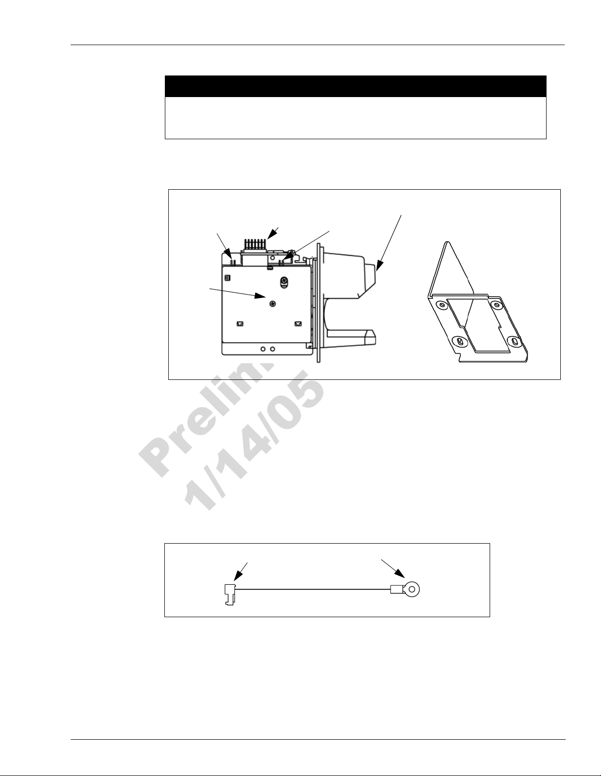
Figure 2: Dual Head Card Assembly and Contactless Smart Bracket
Installation
2 Pin
Antenna
Connector
Printed
Circuit
Card
M03311A001 Dual Head Card Assembly
Attach the contactless smart bracket and card reader to the CIM door and secure using four
4
7 Pin
Power/Data
Connector
2 Pin ESD
Ground
Connection
Card Reader Slot
Contactless Smart Bracket M01180B004
Q11677-24 screws (provided in kit).
5 Reconnect the seven pin power/data cable to the 7 pin power/data connector (Figure 2) on the
card reader printed circuit card.
6 Insert the connector end of the ESD Ground Card Cable M02134A001 (Figure 3) to the two
pin connector (Figure 2) on the card reader.
Figure 3: Encore/Eclipse ESD Ground Cable M02134A001
Connector
Locate the ground ring terminal on the lower portion of monochrome display mounting
7
Ring Terminal
bracket and remove the screw an d washer that secur es the ground conne ction. Retain t he screw
and washer for reinstallation.
8 Connect the ring terminal (Figure 3) of ESD Ground Card Cable M02134A001 to the
monochrome display mounting bracket ground connection. Secure the connection with the
MDE-4199 Contactless Smart Card Ret r ofit Kit M05205K00X Installation Manual • January 2005 Page 9

Installation
screw and lock washer that was removed in the previous step.
9 Ensure that all g round c ables are sec ured to the unit with sufficient slack to prevent cabl e pulls
and pinching.
Page 10 MDE-4199 Contactless Smart Card Re trofit Kit M05 205K00 X Installatio n Manua l • January 2005
Installation
Installing the Antenna PCA
The RF antenna must be located directly behind the area where the PayP ass logo graphic is
attached as shown in Figure 4.
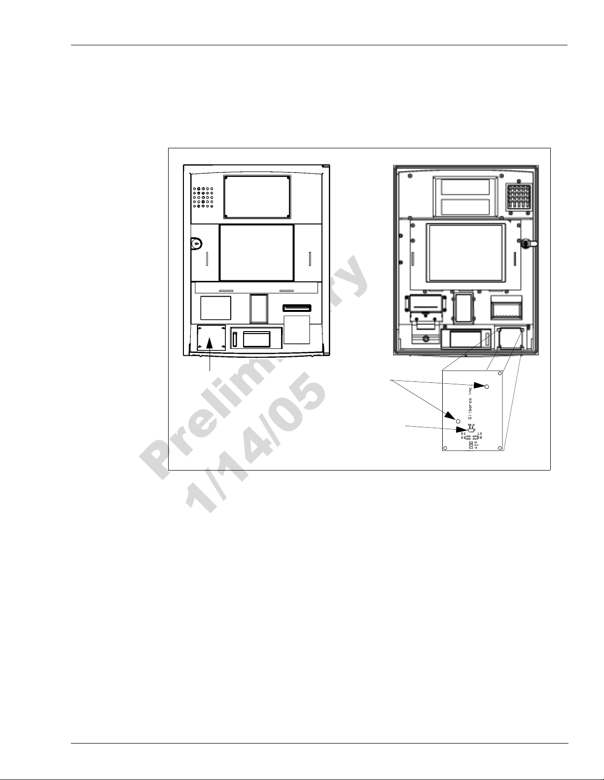
Figure 4: Encore CIM Door Showing Antenna PCA Location
PayPass Logo
Location
Front View
Rear View
Mounting Holes
2 Pin Connector
M05170A001 Antenna PCA
Install the antenna as follows:
1 Locate the area where the antenna PCA will be mounted.
2 Using isopropyl alcohol, clean the mounting surface.
3 Locate the M05170A001 Antenna PCA in the kit and peel the protective cover from the foam
adhesive strips on the antenna.
4 Orient the antenna as shown in Figure 4 and attach it to the CIM door surface by pressing the
foam adhesive firmly against the CIM door.
5 Using two Q11657-290 screws (part of the kit), secure the antenna in place by inserting the
screws in the mounting holes (Figu re 4) and t urn ing the se lf-t appin g screws i nto the CIM door.
6 Connect one end of the M04124 A003 Antenna Cable t o the two- pin conn ector on th e anten na
PCA (Figure 4) and the other end to the 2-pin connector on the dual head card assembly as
shown in Figure 2.
MDE-4199 Contactless Smart Card Ret r ofit Kit M05205K00X Installation Manual • January 2005 Page 11