

Gilbarco GBIR13 User Manual

Introduction
Purpose of this Manual
This manual provides instruction for installing Mat Reader Assembly Kit C00016-XXX.
MDE-4017B
Mat Reader Assembly Kit C00016-XXX
Installation Manual
May 2002
The Mat Reader allows customers to automatically authorize sales using a hand-held
transponder tag.
Important Notice
This equipment has been tested and found to comply with the limits for a Class A digital
device pursuant to Part 15 of the Federal Communications Commission (FCC) Rules. These
limits are designed to provide reasonable protection against harmful interference when the
equipment is operated in a commercial environment. This equipment generates, uses and can
radiate radio freque ncy en er gy, and if not i nstal led and us ed in ac cordanc e with the in struc tion
manual, may cause harmful interference to radio communications. Operation of this
equipment in a residential area is likely to cause harmful interference in which case the user
will be required to correct the interference at his own expense. Changes or modifications not
expressly approved by the manufacturer could void the user’s authority to operate this
equipment.
The long term characteristics or the possible physiological effects of radio frequency
electromagnetic fields have not been investigated by Underwriters’ Laboratories, Inc. (UL
Required Reading
Before installing the equipment, the installer must read, unders tand, and follo w:
• this manual
• NFPA 70, The National Electrical Code (orderable at www.nfpa.org)
Pre
• applicable federal, state and local codes and regulations
Failure to do so may adversely effect the safe use and operation of the equipment.
y
iminar
l
6/
5/1
02
®
).
0
MDE-4017B Mat Re ader Assembly Kit C00016-XXX Installation Manual • May 2002 Page 1

Important Safety Information
Important Safety Information
This section introduces the hazards and safety precautions associated with installing,
inspecting, maintaining or servicing this product. Before performing any task on this product,
read this safety information and the applicable sections in this manual, where additional
hazards and safety precautions for your task will be found. Electrical shock could occur and
cause death or serious injury if these safe service procedures are not followed.
Preliminary Precau tio n s
Read, understand and follow this manual and any other labels or related materials supplied
with this equipment.
Follow the Regulations
There is ap plicable info rmation in: NFPA 70: National Electrical Code (NEC); OSHA
regulations; and federal, state, and lo cal codes which must be fol lowed. Failur e to install,
maintain or service this equipment in accordance with these codes, regulations and standards
may lead to legal ci ta ti ons wi th penalties or af f ect the safe use and oper at ion of the equipment.
y
iminar
l
Pre
0
02
6/
5/1
Page 2 M DE-4 01 7 B Mat Reader Assembly Kit C00016- XXX Insta lla tio n Manu al • May 2002
Safety Symbols and Warning Words
Alert Symbol
This safety alert symbol is used in this manual and on warning labels to alert you to a
precaution which must be followed to prevent potential personal safety hazards. Obey safety
directives that follow this symbol to avoid possible injury or death.
Signal Words
These signal words used in this manual and on warning labels tell you the seriousness of
particular safety hazards. The precautions that follow must be followed to prevent death,
injury or damage to the equipment.
DANGER
This signal word is used to alert you to a hazard or unsafe practice which will result in
death or serious injury.
WARNING
Important Safety Information
y
This alerts you to a hazard or unsafe practice that could result in death or serious injury.
CAUTION
l
This signal word de signa tes a h azard or unsa fe prac tice w hich may res ult in minor injury.
CAUTION
When used by itself, C AUTION de signates a hazard o r unsafe pra ctice whic h may result in
property or equipment damage.
Pre
Proper Grounding is Required
Proper grounding is required for safe operation. See installation manual and applicable NEC,
NFPA and local electrical codes for requirements.
Avoid Pinched Wires
Pinched or cut wires (cables) may damage components. Exposed wires could create sparks and
electrical shorts when applying power.
Other Useful Safety Information
iminar
02
6/
5/1
0
Replacement Parts
Use only genuine Gilbarco replacement parts. Using parts other than genuine Gilbarco
replacement parts could create a safety hazard, violate national, state and local regulations or
void warranty.
Page 3 M DE-4 01 7B Mat Read er Assembly Kit C00016- XXX Insta lla tio n Manu al • May 2002

Reference Information
Reference Information
Related Documents
Installer must obtain, read and understand all site preparation documentation provided by the
point of sale company authorizing the installation before attempting to install this equipment.
In addition, the installer must be familiar with the information in the following documents:
Required Tools
The following equipment is needed to install all Mat Reader kits:
• drill motor and bits
• needle nose pliers
• screwdriver, Phillips
• Zircon
Document
Number Title GOLD
®
MDE-3110 PC-Based G-SITE
MDE-3111 PC-Based G-SITE System Start-Up and Service Manual • G-SITE
®
MDE-3620 Gilbarco
MDE-3982 Advanced Console Application KS000-XXXPC G-SITE
POS Console Site Preparation Manual Site Prep
System Installation Manual G-SITE
iminar
l
®
head
®
stud/bracket finder
02
y
• Service Manual
6/
Coaxial Cable and SMA Connector Handling Re quirements
SM
Library
Coaxial antenna cables are more flexible and have a smaller diameter than more familiar
coaxial cable, such as that used for cable television. However, all coaxial cables share this
Pre
characteristi c: turn s or bends in coaxial cables must be g radual loops, no shar per than a 1-inch
radius or 2-inch diameter (2.54 centimeter radius or 5 centimeter diameter).
5/1
0
CAUTION
Too severe a turn or bend in the cable will break the center (solid) fiber. This can
result in an in termittent signal. It may also result in what app ears to be proper
performance at installation that is followed by premature failure and field service.
In addition, a damaged cable will cause a situation where the transmitter printed
circuit board (PCB) is powered without load, and damage the PCB.
An SMA connector is a type of connector that uses a threa ded mount and co nnec ts one opt ical
fiber. Due to its sma ll size, use care when connecting the coaxi al c abl e to as to not damage t he
SMA connector on the Interface Box or the coaxial cable.
Page 4 M DE-4 01 7 B Mat Reader Assembly Kit C00016- XXX Insta lla tio n Manu al • May 2002

Parts Lists
C00016-006 Kit - Low Frequency
C00016-006 Kits contain the following parts:
Parts Lists
Description Part Number Quantity
box, interface assembly M01814A001 1
tape, neoprene foam M01870B001 2
channel, plastic filler M01871B001 1
cable, mat reader drive M01872A001 1
ferrite half Q11433-110 2
ferrite, snap-on Q11433-107 1
tape, acrylic foam K85492-72 1
power supply M01878B001 1
jack, jump Q1 1011-01 1
cable, data, CAT-5 Q13482-06 1
clamp, cable, stick on, small Q13459-01 3
decal, UL/FCC M01868A001 1
document, installation MDE-4017 1
screw, thread forming, 8-32x3/8” K85736-06 2
C00016-008 Kit - High Frequency
C00016-008 Kits contain the following parts:
iminar
l
y
02
6/
Description Part Number Quantity
box, interface assembly M01814A002 1
Pre
tape, neoprene foam M01870B002 1
channel, plastic filler M01871B002 1
cable, mat reader drive M01872A001 1
transient suppressor, magnetically coupled Q11433-110 2
ferrite, snap-on Q11433-106 1
ferrite, snap-on Q11433-107 1
tape, acrylic foam K85492-72 1
power supply M01878B001 1
jack, jump Q11011-01 10
cable, data, CAT-5 Q13482-06 1
clamp, cable, stick on, small Q 13459-01 3
decal, UL/FCC M01868A002 1
document, installation MDE-4017 1
screw, thread forming, 8-32x3/8” K85736-06 2
5/1
0
Page 5 M DE-4 01 7B Mat Read er Assembly Kit C00016- XXX Insta lla tio n Manu al • May 2002

Parts Lists
C00016-010 Kit - Low Frequency Mini Mat
C00016-010 Kits contain the following parts:
Description Part Number Quantity
box, interface assembly M01814A001 1
tape, neoprene foam M02498B001 1
cable, mat reader drive M01872A002 1
ferrite, snap-on Q11433-107 1
power supply M01878B001 1
jack, jump Q1 1011-01 1
cable, data, CAT-5 Q13482-06 1
clamp, cable, stick on, small Q13459-01 3
®
decal, UL/FCC/IC
see Note
document, installation MDE-4017 1
screw, thread forming, 8-32x3/8” K85736-06 2
Note: “IC:” before the certification/registration number only signifies that the Industry
Canada technical specifications were met.
(Industry Canada),
M01868A003 1
y
Mat Reader
Pre
iminar
l
The following component is also required in addition to the C00016-XXX kit.
Description Part Number (Note) Applicable Kit(s) Quantity
mat reader, small MR01002GXXX C00016-006
mat reader, mini MR01003GXXX C00016-010 1
Note: XXX is the graphic-specific identifier.
5/1
0
6/
02
1
C00016-008
Page 6 M DE-4 01 7 B Mat Reader Assembly Kit C00016- XXX Insta lla tio n Manu al • May 2002
Page 7 M DE-4 01 7B Mat Read er Assembly Kit C00016- XXX Insta lla tio n Manu al • May 2002
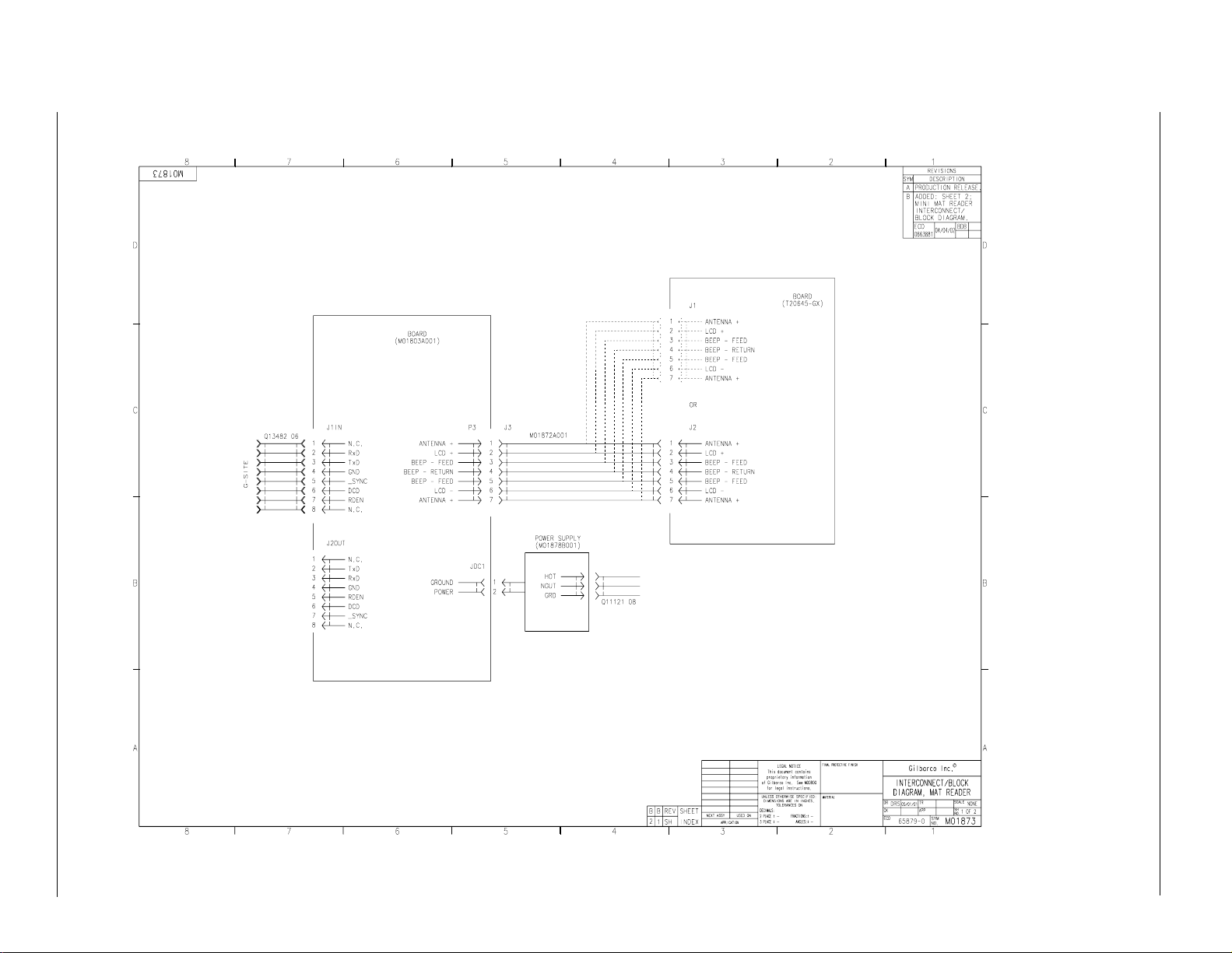
In Interface Box Assembly
M01814A001
Pre
In Mat Reader Assembly
MR01002GXXX
Mat Reader Interconnect/Block Diagram M01873 (Sheet 1)
Interconnect/Block Diagrams
0
DC
+12VDC
5/1
6/
l
iminar
115VAC
02
y
Interconnect/Block Diagrams
Page 8 M DE-4 01 7 B Mat Reader Assembly Kit C00016- XXX Insta lla tio n Manu al • May 2002
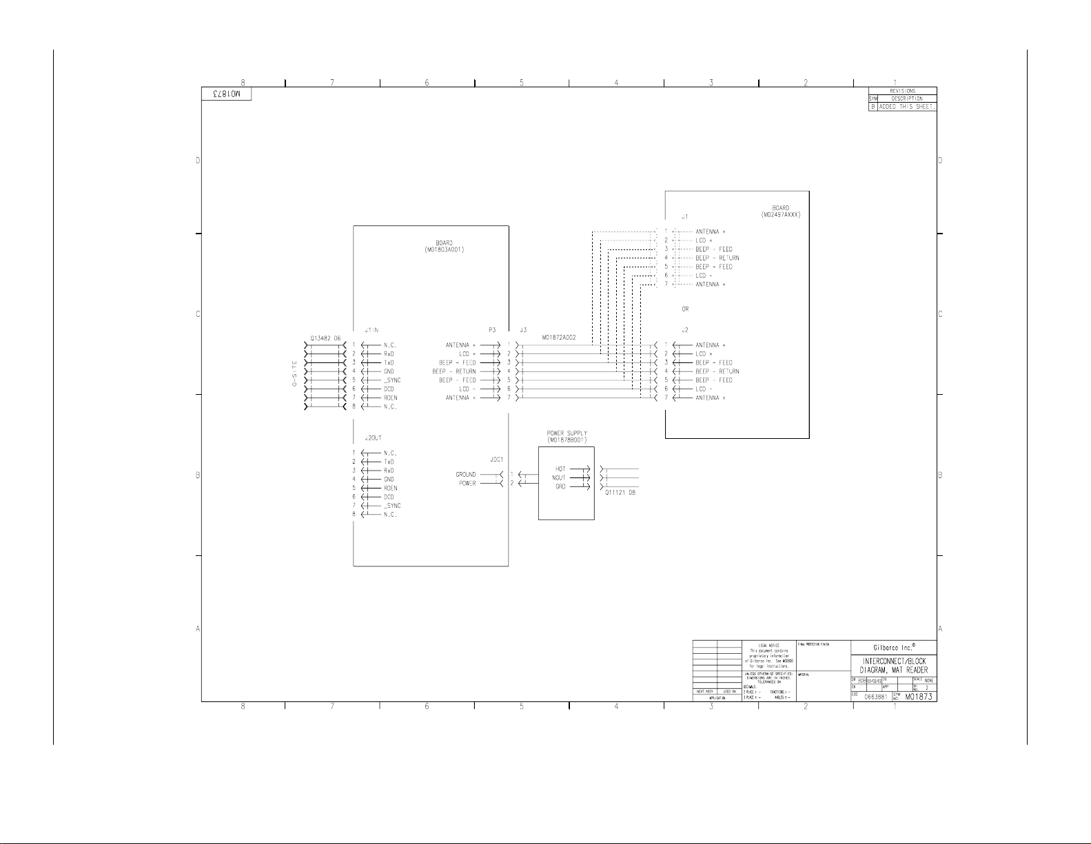
In Interface Box Assembly
M01814A001
Pre
In Mat Reader Assembly
MR01003GXXX
Mat Reader Interconnect/Block Diagram M01873 (Sheet 2)
Interconnect/Block Diagrams
0
5/1
DC
+12VDC
l
iminar
6/
115VAC
02
y
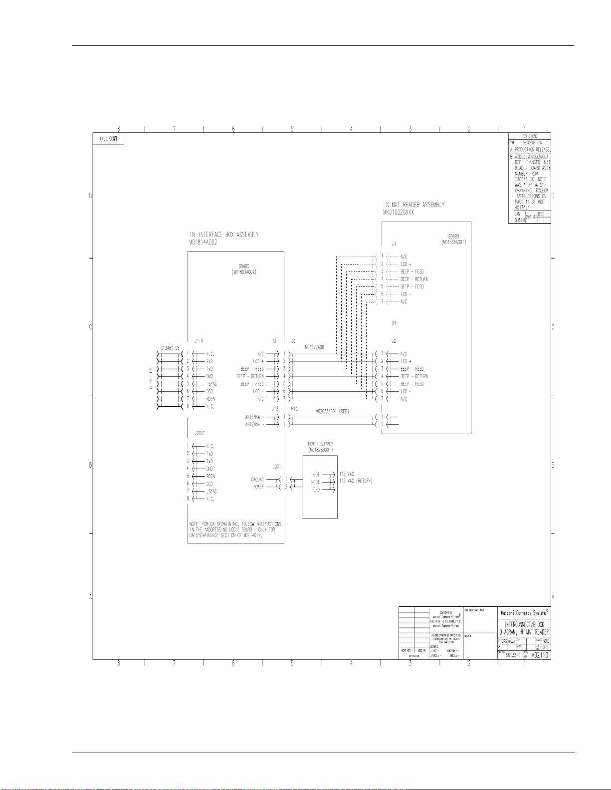
Mat Reader Interconnect/Block Diagram M02110
Interconnect/Block Diagrams
y
iminar
l
Pre
0
02
6/
5/1
Page 9 M DE-4 01 7B Mat Read er Assembly Kit C00016- XXX Insta lla tio n Manu al • May 2002

Installation
Installation
Note: All installation work is to be accomplished between the hours specified by the point of
sale company authorizing the installation.
Install the Mat Reader assembly according to the following instructions.
Collect and arrange for safety and convenience all tools and equipment.
Positioning the Mat Reader
Gilbarco recommends the fol lowing co ncerni ng the place ment o f a Mat Reader on t he counte r
top relative the following devices:
• any cathode ray tube (CRT), such as the point-of-sale (POS) m onitor
• any device with a card reader, such as a personal identification number (PIN) pad
• the Mat Reader Interface Box
• countertop material
In Relation to a CRT
In general, a Mat Reader shoul d be positioned as fa r away as is convenie ntly possible from any
CRT device to avoid interference from the CRT and to ensure optimum performance of the
Mat Reader. The interference from a CRT can vary greatly from unit to unit and model to
model. Also, the presence of nearby masses of metal can affect the influence of a CRT.
There is no universal minimum separation that guarantees trouble-free operation. If the
distance between the Mat Reader and CRT cannot be increased, changing the relative
orientation of these items may yield better operation of the Mat Reader. However, increasing
the distance will always give the most dramatic improvement in Mat Reader performance.
l
y
iminar
02
6/
In Relation to a Card Reader
Pre
In general, any device with a card reader should be positioned as far as is conveniently
possible from a Mat Reader. Since card readers are unshielded, loosely filtered devices, they
are potential vic ti ms of any magnetic interfe ren ce. The M at Rea der ge nerates a magnetic fi el d
as part of its normal operation that can be such a source of magnetic interference to a card
reader.
5/1
0
If a known, good card reader begins to display poor read performance after the addition of a
Mat Reader to the POS system, significant improvements to card reader performance may be
realized by simply increasing its separation from the Mat Reader by as little as a few inches.
As a general rule, placing a card reader beside a Mat Reader has far less effect on the card
reader than actually using the card reader while it is physically on, or held over, the Mat
Reader . A counte r top conf iguration wher e the car d reader co uld be used i n this manne r should
be avoided.
Page 10 MDE-4017B Mat Reader Assembly Kit C00016-XXX Installa tio n Ma nu al • May 2002

Installation
In Relation to the Interface Box
For optimum Mat Reader performance, the Interface Box should be positioned as close to the
Mat Reader as is conveniently possible. If necessary, the CAT-5 cable, Q13482-06, may be
swapped out for a longer v ersio n in orde r to pro perly pl ace th e Interfac e Box a nd stil l reach the
POS connection. The dash number, such as -06, indicates 6 feet (1.8 meters) long.
In Relation to the Countertop Material
If the countertop material is stainless steel, Formica® covered steel, or some other metallic
material, less than desired performance will be experienced. In the preferred setup, the
®
countertop should be Corian
material.
, plastic, wood, or some other non-metallic and/or non-ferrous
y
iminar
l
6/
02
Pre
5/1
0
Page 11 MDE-4017B Mat Reader Assembly Kit C00016-XXX Installa tio n Manu al • May 2002
 Loading...