

Gilat Satellite Networks Skystar 360E Installation Manual

Satellite Modem Installation
May 2003
Document No. DC-0788-20
Gilat Satellite Networks Ltd.
This document contains information proprietary to Gilat Satellite Networks Ltd. and may not be
reproduced in whole or in part without the express written consent of Gilat Satellite Networks Ltd. The
disclosure by Gilat Satellite Networks Ltd. of information contained herein does not constitute any
license or authorization to use or disclose the information, ideas or concepts presented. The contents of
this document are subject to change without prior notice.

Notice
This manual contains information that is proprietary and confidential to Gilat Satellite
Networks Ltd. (hereinafter referred to as Gilat). No part of this publication may be
reproduced in any form whatsoever without prior written approval by Gilat.
No representation or warranties for fitness for any purpose other than that specifically
mentioned in this manual is made by Gilat.
Gilat reserves the right to revise this publication and make changes without obligation to
notify any person of such revisions or changes.
For further information, contact Gilat.
Publication Notice
This manual has been carefully compiled and checked for accuracy. The information in
this manual does not constitute a warranty of performance. Furthermore, Gilat reserves
the right to revise this publication and make changes from time to time in the content
thereof. Gilat assumes no liability for losses incurred as a result of out-of-date or
incorrect information in this manual.
FCC Compliance Notice
This equipment has been tested and found to comply with the limits for a Class B digital
device, pursuant to Part 15 of the FCC Rules. These limits are designed to provide
reasonable protection against harmful interference in a residential installation. This
equipment generates, uses and can radiate radio frequency energy and, if not installed
and used in accordance with the instructions, may cause harmful interference for radio
communications. However, there is no guarantee that interference will not occur in a
particular installation. If this equipment does cause harmful interference to radio or
television reception, which can be determined by turning the equipment off and on, the
user is encouraged to try to correct the interference by one or more of the following
measures:
Reorient or relocate the (radio or TV) receiving antenna
Increase the separation between the equipment and receiver
Connect the equipment into an outlet or a separate circuit from that connected to the
receiver
Consult and experienced radio/TV technician for assistance
Tested to Comply
with FCC Standards
FOR HOME OR OFFICE USE

Contents
Skystar 360E Satellite Modem Installation and Configuration
1. Introduction.........................................................................................................1
2. Satellite Modem 360E Description......................................................................2
2.1 Model 360E Satellite Modem (IDU)........................................................................2
2.1.1 Model 360E Rear Panel (Standard Model)...................................................3
2.1.2 Satellite Modem 360E (4-Port LAN and Serial Port Models) .........................4
2.2 Inter-Facility Link (IFL) Cables...............................................................................5
2.2.1 Coaxial Cables............................................................................................5
2.2.2 LAN Cable ..................................................................................................5
3. Satellite Modem Physical Connections ..............................................................6
4. Configuring and Verifying the Satellite Modem Installation...............................7
4.1 Configuring the Satellite Modem............................................................................7
4.2 Checking the Eb/N0 and BER..............................................................................11
4.3 CW Test Procedure.............................................................................................11
5. Appendix A – Installation of the Skystar 360E Installation Software...............14
6. Appendix B – Support Software Installation and Operation.............................18
6.1 Installation of the Support Software on the Client PC ...........................................18
6.2 Using the VSAT Support Software on a Client PC ................................................22
6.2.1 VSAT IP Connectivity Test ........................................................................25
6.2.2 NMC Connectivity Test..............................................................................25
6.2.3 Internet Connectivity Test..........................................................................26
6.2.4 Reconfigure VSAT ....................................................................................26
6.2.5 Eb/N0 Measurement .................................................................................27
7. Appendix C –Using the SatPointer device to Point the Antenna......................28
7.1 Setting Up for SatPointer Use..............................................................................29
7.2 Maximizing the Satellite Signal Using the SatPointer............................................30
8. Appendix D - Creating a VSAT .lpf Installation File..........................................32
360E SatModem Installation
May, 2003
Proprietary and Confidential
i

Figures
Skystar 360E Satellite Modem Installation and Configuration
Figure 1: Model 360E Satellite Modem – Front View..................................................... 2
Figure 2: Model 360E Satellite Modem – Rear View...................................................... 3
Figure 3: 4 LAN Port Satellite Modem – Rear View....................................................... 4
Figure 4: Serial Port Satellite Modem – Rear View........................................................ 4
Figure 5: ODU and Cable Connections......................................................................... 6
Figure 6: VSAT Installation Desktop Icon...................................................................... 7
Figure 7: Skystar 360E Modem Configuration – Opening Screen – Status Unknown...... 8
Figure 8: ODU Offset................................................................................................... 8
Figure 9: Technical ID.................................................................................................. 9
Figure 10: Skystar 360E Modem Configuration – Status Boot.......................................10
Figure 11: Skystar 360E Modem Configuration – Status Operational............................10
Figure 12: Eb/N0.........................................................................................................11
Figure 13: Technical ID – CW Mode............................................................................12
Figure 14: Enter CW Mode..........................................................................................12
Figure 15: Turning On CW Mode.................................................................................13
Figure 16: Installation Software Icon............................................................................14
Figure 17: VSAT 360E Welcome Screen .....................................................................14
Figure 18: VSAT Installation License Agreement .........................................................15
Figure 19: VSAT Installation – Choose Destination Location........................................15
Figure 20: VSAT Installation – Setup Type ..................................................................16
Figure 21: VSAT Installation – Select Program Folder..................................................16
Figure 22: VSAT Installation – Installation Complete....................................................17
Figure 23: VSAT Installation Shortcut Icon...................................................................17
Figure 24: Support Software Icon................................................................................18
Figure 25: VSAT 360E Support Welcome Screen ........................................................19
Figure 26: VSAT Support Installation License Agreement ............................................19
Figure 27: VSAT Support Installation – Choose Destination Location...........................20
Figure 28: VSAT Support Installation – Setup Type .....................................................20
Figure 29: VSAT Support Installation – Select Program Folder.....................................21
Figure 30: VSAT Support Installation – Installation Complete.......................................22
Figure 31: VSAT Support Icon.....................................................................................22
Figure 32: Support Icon in Tray...................................................................................23
Figure 33: Select Help Desk........................................................................................23
Figure 34: Help Desk Main Screen..............................................................................24
Figure 35: VSAT Connectivity Successful....................................................................25
Figure 36: NMC Connectivity Failed ............................................................................26
Figure 37: Internet Connectivity Successful.................................................................26
Figure 38: Show Eb/N0...............................................................................................27
Figure 39: Eb/N0 and BER Status ...............................................................................27
Figure 40: SatPointer..................................................................................................28
Figure 41: SatPointer Setup ........................................................................................29
Figure 42: SatPointer: No Signal .................................................................................30
Figure 43: SatPointer: Low Signal ...............................................................................30
Figure 44: SatPointer: Eb/N0 Reading.........................................................................30
360E SatModem Installation
May, 2003
Proprietary and Confidential
ii

Tables
Skystar 360E Satellite Modem Installation and Configuration
Table 1: Front Panel LEDs............................................................................................2
Table 2: Rear Panel Features .......................................................................................4
Table 3: System Connectivity Status...........................................................................25
360E SatModem Installation
May, 2003
iii
Proprietary and Confidential

About This Manual
This section describes the objectives, audience, document layout and conventions of
the Skystar 360E Satellite Modem Installation manual.
Objectives
This manual provides detailed instructions showing how to install the Skystar 360E
Satellite Modem and configure its software.
How to Use This Manual
This manual is to be used as a reference guide during the installation of the Skystar
360E Satellite Modem and its configuration.
Audience
This manual is designed for personnel who have been trained in the installation and
configuration procedures for the Skystar 360E Satellite Modem.
Skystar 360E Satellite Modem Installation and Configuration
Organization
The table below contains a list of the chapters in the manual, the chapter titles and a
short description of the material contained in each chapter.
Chapter Chapter Title Description
Chapter 1 Welcome A short description of the Skystar 360E
Chapter 2
Chapter 3
Chapter 4
Chapter 5
Chapter 6
Satellite Modem
Description
Satellite Modem
Physical Connections
Configuring the
Satellite Modem
Appendix A Installation of the
Skystar 360E
Installation software
Appendix B Support Software
Installation and
Operation
system
Details of the Satellite Modem 360E from
and back panels and their connections
Physical installation of the Satellite Modem
360E and its connections
Configuration of the Satellite Modem using
the Installation software
How to install the Installation software on
the installer’s PC
How to install and use the Support software
on a client PC in the network
360E SatModem Installation
May, 2003
Proprietary and Confidential
iv

Skystar 360E Satellite Modem Installation and Configuration
Chapter Chapter Title Description
Chapter 7
Chapter 8
Appendix C –Using
the SatPointer device
to Point the Antenna
Appendix D Creating a VSAT .lpf
Installation File
Describes the SatPointer device and how to
use it in pointing the VSAT Antenna
How to create an .lpf configuration file at
the NMS
360E SatModem Installation
May, 2003
Proprietary and Confidential
v
Conventions
Skystar 360E Satellite Modem Installation and Configuration
This manual uses the following conventions to convey instructions and information:
Convention Description
Boldface font
Commands and keywords.
Italic font
Screen font
9999
This warning symbol means danger. It is used to describe a
situation that can cause bodily injury. Before working on any
equipment, be aware of the hazards involved with electrical circuitry
and how to prevent accidents.
This symbol means reader be careful. In this situation, damage may be
caused to equipment or data may be lost
This symbol means reader take note. Notes contain helpful suggestions
and explanations.
The result of an instruction or command.
Information to be typed into a form or dialog
box.
Indicates a space in a CLI command.
WARNING
CAUTION
.
NOTE
360E SatModem Installation
May, 2003
Proprietary and Confidential
vi
1. Introduction
Skystar 360E Satellite Modem Installation and Configuration
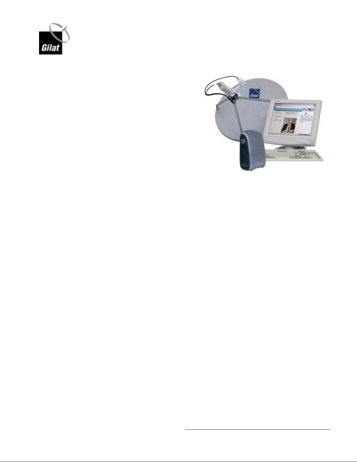
Skystar
TM
360E is a private/shared
VSAT network designed for twoway IP and multicast applications.
The product is ideally suited for
web-based intranet and Internet
access, as well as for private and
shared IP networks where
headquarters or data centers
communicate with hundreds to
thousands of geographically
dispersed sites.
Skystar 360E is a versatile VSAT
product that integrates and features multiple applications on one platform. The same
network can be used for interactive IP communications, as well as for IP multicasting
and video/audio streaming.
The two- way functionality allows for high levels of interaction, feedback and access
to resources. With DVB compliant Outbound and extensive IP capabilities, Skystar
360E supports virtually any data and IP multicast application.
360E SatModem Installation
May, 2003
Proprietary and Confidential
1

2. Satellite Modem 360E Description
2.1 Model 360E Satellite Modem (IDU)
The Model 360E Satellite Modem connects to the client’s PC either directly via a
LAN or USB cable. Two coaxial cables connect the ODU to the modem. Model 360E
Front Panel
The front view of the Model 360E Satellite Modem is shown in Figure 1.
Skystar 360E Satellite Modem Installation and Configuration
360E SatModem Installation
May, 2003
Figure 1: Model 360E Satellite Modem – Front View
The front panel contains a number of LEDs. Their functions are described in Table 1.
Table 1: Front Panel LEDs
LED Function
PWR On when power is connected
Rx On when Receiver card is receiving data
SYN On when modem is connected to hub
CON On when communication link is active
Tx Blinks when signal is transmitted to hub
PC On when connection to PC is active
Proprietary and Confidential
2
Skystar 360E Satellite Modem Installation and Configuration
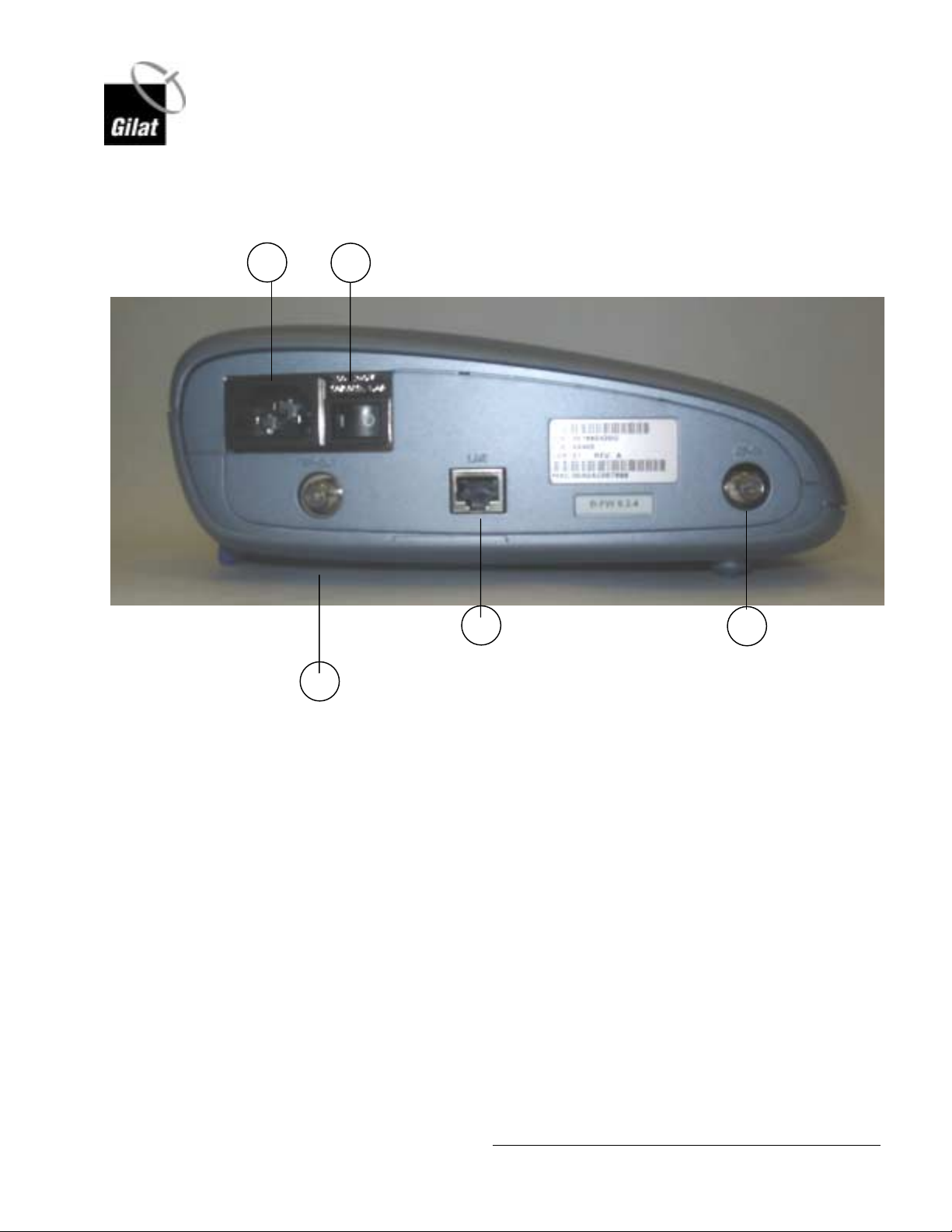
2.1.1 Model 360E Rear Panel (Standard Model)
The rear view of the Model 360E Satellite Modem is shown in Figure 2.
1
2
4
5
3
Figure 2: Model 360E Satellite Modem – Rear View
360E SatModem Installation
May, 2003
A description of the elements located in the rear of the modem is found in Table 2.
Proprietary and Confidential
3
Skystar 360E Satellite Modem Installation and Configuration
Table 2: Rear Panel Features
No. Description Purpose
1 Power Socket 100-240V, 50/60 Hz, 2A male connector for power cord
2 On/Off Switch Power Modem On/Off
3 RF Out Coax Connector Connect modem to Input Port HPC on ODU
4 LAN Port Connect Client PC to modem via LAN cable
5 RF In Coax Connector Connect modem to Output Port LNB on ODU
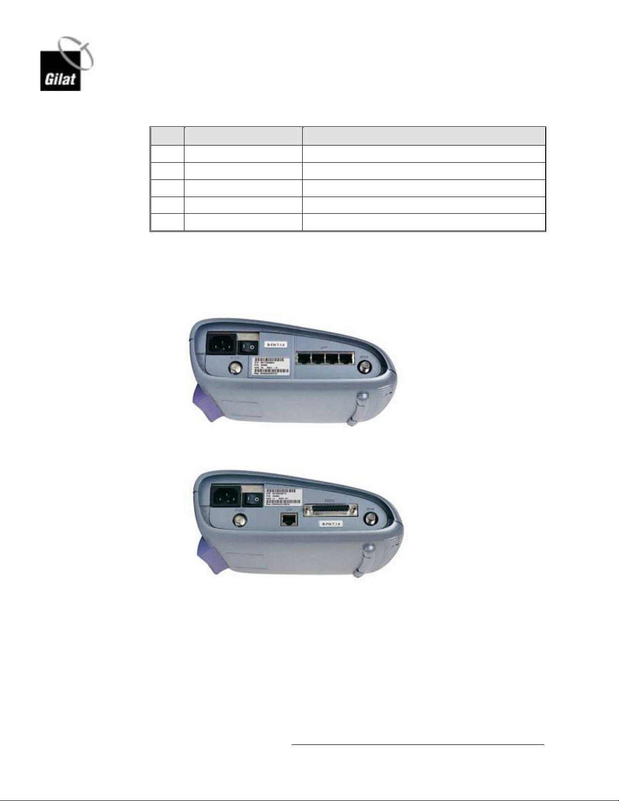
2.1.2 Satellite Modem 360E (4-Port LAN and Serial Port Models)
Rear view of the 4 Port LAN and Serial Port models are shown in Figure 3 and
Figure 4. The connections are similar to those shown in Figure 2.
Figure 3: 4 LAN Port Satellite Modem – Rear View
Figure 4: Serial Port Satellite Modem – Rear View
360E SatModem Installation
May, 2003
4
Proprietary and Confidential
 Loading...