

Suricate – Iridium Optical Link Page | 1
Operating User Manual
Copyright 2011

Suricate – Iridium Optical Link Page | 2
Table of Contents
Iridium Repeater System Error! Bookmark not defined.
Operating User Manual 1
Important information 4
Warranty and repair 4
General Warranty 4
Specific Product Warranty Instructions 4
Returns 4
Limitations of Liabilities 5
Reporting Defects 5
Precautions 6
1. Introduction to the Iridium repeater system 7
1.1. System component 8
Indoor unit 8
Outdoor unit 8
1.2. Product drawing 9
1.2.1. Indoor unit 9
1RU Chassis front view 9
1RU Chassis rear view 9
LED Description 9
1RU Chassis Module identification (Top view) 10
Designation chart 10
1.2.2. Compact indoor unit 11
Compact enclosure front view 11
Compact enclosure rear view 11
1.2.3. Outdoor unit 12
ODU front view 12
ODU LED Description 12
ODU connector and module identification 13
MGC potentiometers 13
Optical & RF Connector’s layout 13

Suricate – Iridium Optical Link Page | 3
Designation chart 13
1.3. System Diagram 14
2. Installation 15
2.1. Connecting the fiber optic cables 15
2.2. Setting up the indoor unit 16
2.2.1. Installing the 1U chassis 16
2.2.2. Powering the indoor Iridium unit 16
2.3. Setting up the outdoor unit 17
2.3.1. Installing the Outdoor unit 17
2.3.2. Connecting the Input/output/power cables 18
2.3.3. Mounting the outdoor antennas 18
2.3.4. Powering the outdoor Iridium unit 18
3. Product technical description 19
3.1. System specification 19
3.2. Model dimension 20
3.2.1. Outdoor unit 20
3.2.2. Indoor unit 21
3.3. ODU AC Connector assembly 21
4. Troubleshooting and optical connector cleaning 22
4.1. Troubleshooting the IDU 22
Troubleshooting the ODU (Cont) 23
4.2. Cleaning fiber optic Connections 24
4.2.1. Cleaning procedure for FC-APC connectors 25
4.2.2. Cleaning procedure for FC-APC Connectors 25

Suricate – Iridium Optical Link Page | 4
Important information
Warranty and repair
Gilat Satcom (“Gilat”) performs testing and inspection to verify the quality and reliability of our
products. Gilat uses every reasonable precaution to ensure that each unit meets specifications before
shipment. Customers are asked to advise their incoming inspection, assembly, and test personnel as to
the precautions required in handling and testing our products. Many of these precautions are to be
found in this manual.
The products are covered by the following warranties:
General Warranty
Gilat warrants to the original purchaser all standard products sold by Gilat to be free of defects in
material and workmanship for 24 months from date of shipment from Gilat. During the warranty period,
Gilat will repair or replace any product that has been proved to be defective. This warranty does not
apply to any product which has been subject to alteration, abuse, improper installation or application,
accident, electrical or environmental over-stress, negligence in use, storage, transportation or handling.
Specific Product Warranty Instructions
All Gilat products are warranted against defects in workmanship, materials and construction, and to no
further extent. Any claim for repair or replacement of units found to be defective on incoming
inspection by a customer must be made within 30 days o f receipt of shipment, or within 30 days of
discovery of a defect within the warranty period.
This warranty is the only warranty made by Gilat and is in lieu of all other warranties, expressed or
implied. Gilat sales agents or representatives are not authorized to make commitments on warranty
returns.
Returns
In the event that it is necessary to return any product against above warranty, the following procedure
shall be followed:
1. Return authorization is to be received from Gilat prior to returning any unit. Advise Gilat of the
model, serial number, and discrepancy. The unit may then be forwarded to Gilat, transportation
prepaid. Devices returned collect or without authorization may not be accepted.
2. Prior to repair, Gilat will advise the customer of our test results and any charges for repairing
customer-caused problems or out-of-warranty conditions etc.
3. Repaired products are warranted for the balance of the original warranty period, or at least 90
days from date of shipment.

Suricate – Iridium Optical Link Page | 5
Limitations of Liabilities
Gilat’s liability on any claim, of any kind, including negligence for any loss or damage arising from,
connected with, or resulting from the purchase order, contract, quotation, or from the performance or
breach thereof, or from the design, manufacture, sale, delivery, installation, inspection, operation or use
of any equipment covered by or furnished under this contact, shall in no case exceed the purchase price
of the device which gives rise to the claim.
EXCEPT AS EXPRESSLY PROVIDED HEREI N, GILAT MAKES NO WARRANTY, EXPRESSED OR I MPLIED, WITH RESPECT TO ANY
GOODS, PARTS AND SERVICES PROVIDED I N CONNECTION WITH THI S AGREEMENT INCLUDING , BUT NOT LIMITED TO, THE
IMPLIED WARRANTIES OF MERCHANTABILITY AND FITNESS FOR A PARTI CULAR PURPOSE. GILAT SHALL NOT BE LIABLE FOR ANY
OTHER DAMAGE INCLUDING , BUT NOT LIMITED TO, INDIRECT, SPECIAL OR CONSEQUENTIAL DAMAGES ARISING OUT OF OR IN
CONNECTION WITH FURNISHING OF GOODS, PARTS AND SERVICE HEREUNDER, OR THE PERFORMANCE, USE OF, OR INABILITY
TO USE TH E GOODS, PARTS AND SERVICE.
The Company's exclusive warranty and the remedy provided for breach there of shall not apply to:
1. Any product used or operated other than pursuant to the Company's written instructions,
2. Damage or deficiencies resulting from accident, alteration, modification, misuse, tampering,
negligence, improper maintenance, installation or abuse,
3. Use of any product other than at the Installation Site,
4. Use of any Product that is defective or damaged due to misuse, accident, or neglect, or due to
external electrical stress, lightning or other acts of nature,
5. Use of any Product by a person who is not any authorized employee of the Customer, or
6. Used other than as explicitly authorized in writing by the Company.
Reporting Defects
The units were inspected before shipment and found to be free of mechanical and electrical defects.
Examine the units for any damage which may have been caused in transit. If damage is discovered, file a
claim with the freight carrier immediately. Notify Gilat as soon as possible.
Note: Keep all packing material until you have completed the inspection.

Suricate – Iridium Optical Link Page | 6
Precautions
Personal Safety
Applying power to the transmitter unit will create a laser energy source operating in Class I as defined by
IEC 825-1. Use either an infrared viewer, optical power meter or fluorescent screen for optical output
verification.
AC Power Hazard
The rack mount power supply line is EMI filtered. The chassis is connected to earth ground in
compliance with safety requirements. Always use the 3-prong AC plug with earth ground to avoid
possibility of electrical shock hazard to personnel.
Grounding
See section 2.3.2 for instructions on how to connect the ODU’s main grounding point. Do not attempt to
install the ODU before grounding the unit at this point.
The unit should be installed according to NEC/CEC.
Equipment Safety
To avoid damaging your product, please observe the following:
1. The transmitter input and receiver output are DC coupled and can withstand the bias from a
satellite receiver. Do not exceed 25V DC bias.
2. The input of the outdoor unit transmitter (L-Band uplink) and may have an optional built-in bias
for inserting DC power up the coax to the LNB. Make certain any equipment or test equipment
connected to the transmitter input can withstand this bias.
3. Do not allow any dirt or foreign material to get into the optical connector bulkheads. This may
cause damage to the polished optical connector end faces.
4. The optical fiber jumper cable bend radius is 3 cm. smaller radii can cause excessive optical loss
and/or fiber breakage.
5. If multiple chassis are installed in a Rack, allow sufficient room for adequate ventilation;
otherwise the units may overheat causing possible safety hazard or equipment damage.
6. Make sure the unit is grounded!

Suricate – Iridium Optical Link Page | 7
1. Suricate PRO wireless Iridium link - Introduction
Iridium Communications Inc. is a satellite communications company that offers truly global
voice and data communications coverage. Iridium is advancing the way global enterprises
conduct daily mission-critical activities through reliable, near real-time, communications
services.
Iridium's 66 low-Earth orbiting (LEO) cross-linked satellites – the world's largest commercial
constellation – operate as a fully meshed network that is supported by multiple in-orbit
spares.
Iridium solutions are ideally suited for industries such as maritime, aviation,
government/military, emergency/humanitarian services, mining, forestry, oil and gas, heavy
equipment, transportation and utilities.
Iridium satellite phones and terminals need line-of-sight to open sky in order to function.
Units will not work consistently indoors, or under forest cover.
Suricate PRO wireless Iridium link is a fiber based Bi-Directional repeater transport system
that can be used for iridium satellite signals.
Gilat’s Suricate PRO system helps create a virtual Iridium satellite coverage inside a building
a bunker or enclosed facility.
Suricate PRO wireless Iridium link supports 3 simultaneous phone calls and extends GPS
location signals.
Suricate – Iridium Optical Link Page | 8
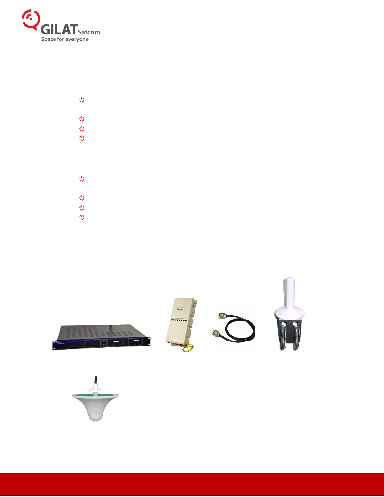
1.1. System component
The Iridium optical link consists of the following components:
Indoor unit
1U indoor chassis equipped with dual hot swappable power supply and Iridium optical
transceiver.
Dual ceiling mount distribution antennas.
Dual 5M low loss coax cable.
In the case of the compact version, a compact indoor chassis supplied with a wall mount
power supply.
Outdoor unit
ODU enclosure equipped with Iridium optical transceiver, high power amplifier and
mounting Kit.
Dual Iridium antennas with pole mount kit.
Dual 1.5M low loss coax cable.
100Meter pre terminated fiber cable
X1 x1 x2 x2
x2

Suricate – Iridium Optical Link Page | 9
Opt RFOpt RF
MGC
Opt RF
MG
C
Transmitter
xxx -1M
Test
Opt RF
MG
C
xxx -1M
Test
Receiver
MGC
AC
Opt-2
AC
Opt-1
RF In
19"
1.75"
RF Out
Transmitter LEDs
Led Name
Led Function
Laser
Indicates that laser is functioning
RF
Not Available
Receiver LEDs
Led Name
Led Function
Opt
Indicates that optical RX is receiving
minimum required amount of optical
power (light)
RF
Not Available
1.2. Product drawing
1.2.1. Indoor unit
1RU Chassis front view
1RU Chassis rear view
LED Description
On the front panel of the Iridium indoor unit are 4 LEDs.

Suricate – Iridium Optical Link Page | 10
Power
Protection
Circuit
PS2
PS1
Pwr
M&C
Pwr
M&C
Pwr
M&C
OPT 2
AC
AC
RF
OPT
OPT
RF
RF
OPT
Slot 4
Empty
Slot 1
Iridium Transmitter
OPT 1
Slot 2
Iridium Receiver
Pwr
M&C
RF
OPT
Slot 3
Empty
FC-APC
FC-APC
SMA
SMA
Slot number
1
2
Module name/Description
Iridium optical
Transmitter
Iridium optical Receiver
RF Connector used
1
2
Optical connector used
1
2
Connector type
SMA
SMA
Gain Control
MGC1 (front panel)
MGC2 (front panel)
1RU Chassis Module identification (Top view)
Designation chart

Suricate – Iridium Optical Link Page | 11
Opt In
Opt Out
RF In
Opt
Opt
RF Out
1.2.2. Compact indoor unit
Compact enclosure front view
Compact enclosure rear view
Suricate – Iridium Optical Link Page | 12
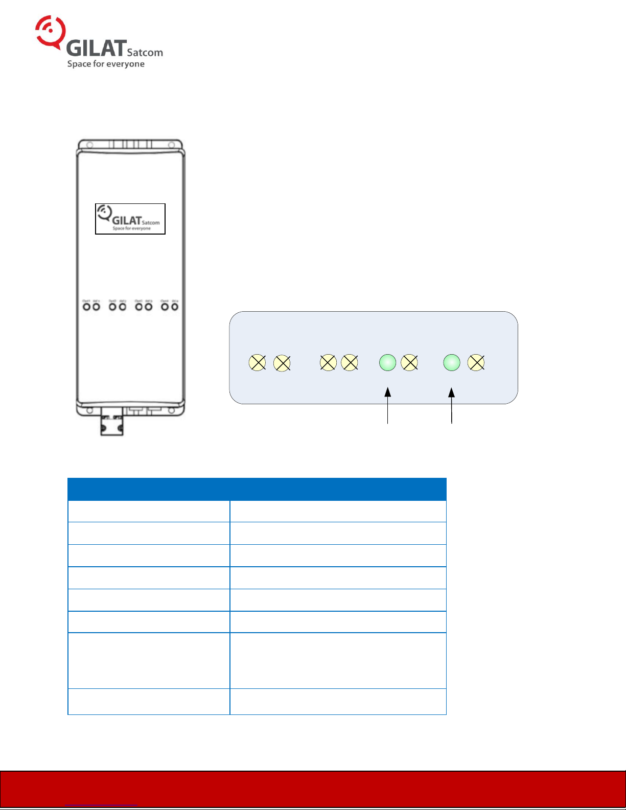
\\
TX
RX
Opt3 Opt4 Opt2 Opt1 RF1 RF2 RF1 RF4
Led Name
Led Function
Opt 1
Not Available
RF 1
Not Available
Opt 2
Not Available
RF 2
Not Available
Opt 3
Indicates that laser is functioning
RF 3
Not Available
Opt 4
Indicates that optical RX is receiving
minimum required amount of optical
power (light)
RF 4
Not Available
1.2.3. Outdoor unit
ODU front view
ODU LED Description

Suricate – Iridium Optical Link Page | 13
RF 3
PWR
LED
RF 4
OPT
3
OPT
4
OPT
1
OPT
2
Slot number
3
4
Module name/Description
Iridium optical
Transmitter
Iridium optical Receiver
RF Connector used
3
4
Optical connector used
1
2
Connector type
N-Type
N-Type
Gain Control
MGC3
MGC4
ODU connector and module identification
The Iridium ODU holds two optical modules and a high power RF amplifier.
MGC potentiometers
Optical & RF Connector’s layout
Designation chart

Suricate – Iridium Optical Link Page | 14
OPT2
Gilat
Opt 3
Opt 4
RF 3
RXTX
Iridium ODU
RF 4
4Meter Minimum
OPT1
SMA
Iridium IDU
5Meter cable 1.5Meter cable
SMA
RX Indoor
antenna
TX Indoor
antenna
1.3. System Diagram

Suricate – Iridium Optical Link Page | 15
2. Installation
2.1. Connecting the fiber optic cables
Before connecting the cable
The fiber cable must be either fusion spliced or connected via FC/APC
connectors
Wipe the connector with a lint-free cotton cloth.
Note the polarity key of the optical connector before inserting
To connect the fiber optic cable Line up the polarity key:
Line up the polarity key
Insert the connector
Tighten the connector

Suricate – Iridium Optical Link Page | 16
2.2. Setting up the indoor unit
The indoor 1U chassis provides power to the optical transceiver. The 1U Chassis is equipped
with two redundant power supplies. The power supply provides a stable 13vdc and its feed
by an AC input of 100-240VAC 50/60Hz, with a max current consumption of 0.5A.
To power up the compact indoor enclosure apply 12VDC via the DC Jack using the supplied
wall mount power supply.
2.2.1. Installing the 1U chassis
Install the system inside a 19” rack.
Allow 1” of space on top of the unit for proper cooling
2.2.2. Powering the indoor Iridium unit
Apply AC power to the Chassis
On the front panel OPT1 LED should be “ON”.
using an optical power meter (If available) verify outgoing optical power of
+1 to +4dBm
Connect fiber optic cables to the unit
Connect RF cable from ceiling mount antenna to the Indoor Iridium chassis

Suricate – Iridium Optical Link Page | 17
2.3. Setting up the outdoor unit
The power supply provides:
Stable 13vdc
AC input 100-230VAC 50/60Hz, 0.5A
2.3.1. Installing the Outdoor unit
2.3.1.1. Hanging the outdoor unit on a pole
The ODU can be installed on a pole. The installation pole can be at maximum of
45°. The pole diameter must be between 1. 2” to 1.9” (30 - 50 mm).
Place the first bracket on the outer side of the pole. Using two screws screw the
bracket to top of the ODU.
Place the second bracket on the outer side of the pole. Using two screws, screw the
bracket to bottom of the ODU.
Using one screw, secure each bracket to the pole.
Note Screw length depends on the width of the pole.
2.3.1.2.
2.3.1.2 Hanging the outdoor unit on a wall
Caution: The ODU is heavy! Make sure that the wall can support its weight (5 kg.)Suitable
bolts must be used. Foxcom recommends that the ODU be installed on a concrete walls
Using the drill sheet provided drill four holes (5/16”) through the markings indicated on
the paper.
Using the drilled holes as a guide, place the ODU on the wall.
Using four screws, secure the ODU to the wall.

Suricate – Iridium Optical Link Page | 18
2.3.2. Connecting the Input/output/power cables
WARNNING: UNIT MUST BE GROUNDED BEFORE APPLYING POWER
To Ground the unit assemble the ground assembly.
Connect optical fibers and cover them using the supplied weather cover protection
2.3.3. Mounting the outdoor antennas
WARNNING: ANTENNA MUST BE CONNECTED BEFORE APPLYING POWER
Using the short supplied RF coax cable connect the receive (Downlink) antenna on top of
the ODU
Using the supplied long RF coax cable connect the transmit (Uplink ) antenna on a pole 2.5
M form the ODU
Note: antenna must be installed with a minimum of 2.5 meter from one another. A
recommended installation distance is 4meter.
2.3.4. Powering the outdoor Iridium unit
Apply AC power
On the front panel OPT3 LED should be “ON”
using an optical power meter (If available) verify outgoing optical power of +1 to +4dBm
Connect fiber optic cables to the outdoor unit (see section 2.1 for instruction).
Once the fibers are connected, verify that the front panel OPT4 LED is “ON”

Suricate – Iridium Optical Link Page | 19
Iridium Optical Repeater Specifications
Downlink
Frequency range
1500-1650MHz
ODU input/IDU output VSWR
1:1.6
ODU RF i nput signal range [total power]
up to –20dBm
Downlink Gain1
40dB (±10dB Adjustable)
Nois e Figure
<5dB
Uplink
Frequency range
1600-1650MHz
IDU i nput/ODU output VSWR
1:1.6
IDU RF input signa l range [tota l power]
up to +30dBm
Uplink Gain1
40dB (±10dB Adjustable)
Nois e Figure
<5dB
Optical Specifications
Required fiber type
Dual SMF-28 or equivalent [single mode]
Optical wavelength
1310 ±10nm
IDU/ODU optical power output
-3dBm / 0.5mW (Min)
Optical conne ctor
FC-APC
Fiber length
3Km max (2dB).
Physical Specifications
Indoor
Outdoor
RF Connectors
Single SMA Female
Dual N-Type Female
Dime ns ions
19” Wide 1U Chassis
14” x 6” x 3”
Opera ting tempera ture
-20 to +55° C
-30 to +55° C
Opera ting volta ge
100-240VAC 50/60Hz
100-240VAC 50/60Hz
All specifications are subject to change without notice
3. Product technical description
3.1. System specification

Suricate – Iridium Optical Link Page | 20
3.2. Model dimension
3.2.1. Outdoor unit

Suricate – Iridium Optical Link Page | 21
19"
17.5"
Pin
Function
A
110 to 220VAC ~
B
0 (Neutral)
C
Ground
A B
C
3.2.2. Indoor unit
3.3. ODU AC Connector assembly

Suricate – Iridium Optical Link Page | 22
Problem
Possible cause
Laser LED not ON (TX)
1. No DC power to the unit. Possible
power supply problem. Check the
power supply fuse.
2. If a power meter is available, verify the
optical light output. The power should
be minimum -3dBm [0.5mW]
If any or all the above are not within the
guidelines, the laser or lasers circuit are
defective.
OPT LED not ON (RX)
1. Not enough light or no light at all
arrives to the receiver input.
If a power meter is available make sure that
minimum of -3dBm arrives to the unit.
If lower optical power arrives please refer to
section 4.2, page 24 Optical cleaning fiber
optic connectors.
4. Troubleshooting and optical connector cleaning
4.1. Troubleshooting the IDU

Suricate – Iridium Optical Link Page | 23
Problem
Possible cause
Laser LED not ON (TX)
1. No DC power to the unit. Possible
power supply problem. Verify AC
connector is assembled correctly
2. If a power meter is available, verify the
optical light output. The power should
be minimum -3dBm [0.5mW]
If any or all the above are not within the
guidelines, the laser or lasers circuit are
defective.
OPT LED not ON (RX)
2. Not enough light or no light at all
arrives to the receiver input.
If a power meter is available make sure that
minimum of -3dBm arrives to the unit.
If lower optical power arrives please refer to
section 4 page 24- Optical cleaning fiber optic
connectors.
Troubleshooting the ODU (Cont)

Suricate – Iridium Optical Link Page | 24
Description
Manufacturer
Kim Wipes
Kimberly Clark
Cletop Automatic
Connector cleaner
Cletop
Fiber optic Swab
Cletop or FIS
4.2. Cleaning fiber optic Connections
The unit has an FC/APC angle polished optical connector for very high optical return loss
performance. The units are specified into single mode fiber i.e. 9/125 micron core diameter. Full
performance is specified only for low return loss optical plant - meaning that the fiber must be
fusion spliced and all connections or splices must have a return loss greater than -60 dB. With these
guidelines in mind, link lengths beyond 20 kilometers (DFB based products) can be achieved with
high performance. Specific performance and/or design assistance is available by request from
Foxcom.
If there is low/no signal or noisy signal at the module, the connector should be cleaned. Dirt on the
inside connector tip can impair the flow of light causing problems in signal transmission. The
modules are sealed but dirt can occasionally enter during installation and alignment.
The input and output optical ports of all Gilat Satcom equipment are known in the fiber optic world
as bulkhead ports. Gilat Satcom uses FC/APC connectors.
The following materials are representative of the types of cleaning materials that should be used for
cleaning the fiber optic ports and connectors. They are available from several suppliers.
Cleaning material
Wiping clothes should be made of lint free alcohol free nonabrasive materials. Swabs should have a
tightly wrapped tip and be talcum-free. For removing dust from receptacles, a canned compressed
gas is recommended. Do not use commercial compressed air because of risk of contamination.

Suricate – Iridium Optical Link Page | 25
4.2.1. Cleaning procedure for FC-APC connectors
Use a Kim Wipe to gently wipe the end face surface of the connector. Alternatively a Cletop
automatic connector cleaner can be used.
4.2.2. Cleaning procedure for FC-APC Connectors
Caution: Clean the transmitter and receiver optical ports only when there is evidence of
contamination or reduced performance. A regular maintenance is not needed.
Using a clean fiber optic cleaning swab, gently wipe out the optical port. Discard the swab after
use.
 Loading...