

Giken Trastem VC-1020 Installation Manual
CONFIDENTIAL
VC-1020 Sensor Unit
Installation Manual
Contents
1. SAFETY INDICATIONS ............................................................................................................................... 2
2. INTRODUCTION .......................................................................................................................................... 1
3. SYSTEM DIAGRAM / INSTALLATION WORK DETAILS ......................................................................... 1
4. SENSOR UNIT INSTALLATION AND WIRING ......................................................................................... 2
5. SENSOR INSTALLATION LOCATION EXAMPLE .................................................................................... 4
6. SENSOR DESCRIPTION............................................................................................................................ 6
7. SENSOR UNIT INSTALLATION ................................................................................................................. 7
8. WEB SETTINGS ........................................................................................................................................ 11
9. CONNECT TO NETWORK ....................................................................................................................... 11
10. SENSOR UNIT SPECIFICATIONS .......................................................................................................... 12
11. REMARKS FOR POE (POWER OVER ETHERNET) SWITCHING HUB ............................................ 13
System :
VC-1020 Sensor Unit
Issued :
Nov. 25th 2015 [2nd Edition]
Issued by :
Giken Trastem Co., Ltd.
Distribution to:
Sensor Installer, Installation Engineer
Version:
IM-VC1020-1511-2-EN
CONFIDENTIAL
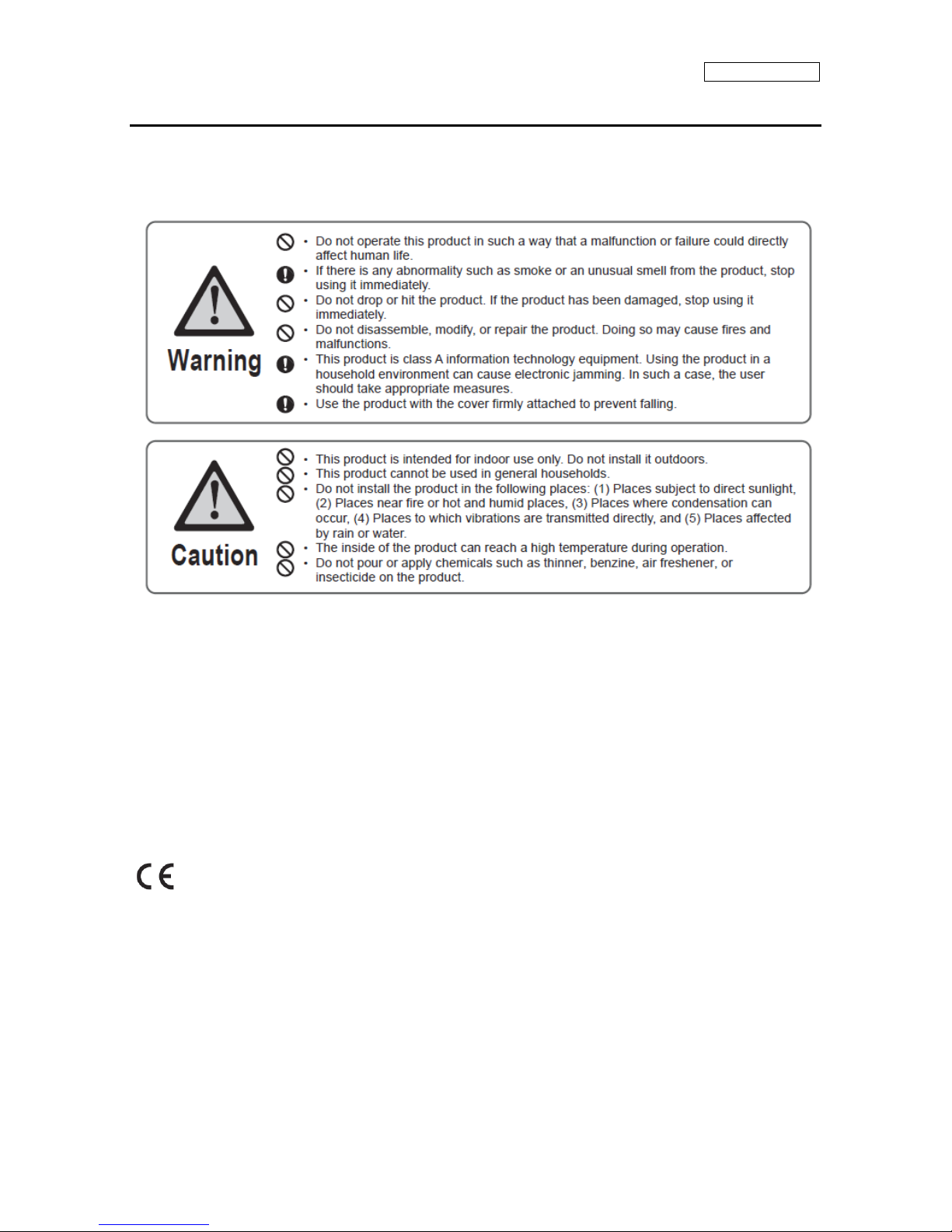
1. SAFETY INDICATIONS
This section provides notes to use the product safely. Please read this section carefully to ensure proper and safe
use of the product.
FCC Part 15 Subpart B Class A
This device complies with part 15 of the FCC Rules.
Operation is subject to the following two conditions:
(1)This device may not cause harmful interference.
(2)This device must accept any interference received, including interference that may cause undesired operation.
This equipment has been tested and found to comply with the limits for a Class A digital device, pursuant to part 15 of the
FCC Rules. These limits are designed to provide reasonable protection against harmful interference when the equipment
is operated in a commercial environment. This equipment generates, uses, and can radiate radio frequency energy and, if
not installed and used in accordance with the instruction manual, may cause harmful interference to radio
communications. Operation of this equipment in a residential area is likely to cause harmful interference in which case the
user will be required to correct the interference at his own expense.
The CE marking indicates compliance to 2004/108/EC EMC Directive with Standards EN55022 Class A ;
EN55024
Giken Trastem assumes no responsibility if the installation and wiring connection which are stated in the instruction
manual provided together with this product is not carried out, or when product without CE marking is connected to this device.
Conditions of use:
This product is not intended for use in any safety-critical or personal safety application. GIKEN TRASTEM assumes no liability
for any accident resulting in personal injury, death, or property damage if this product has been used in the above conditions.
CONFIDENTIAL
1
IM-VC1020-1511-2-EN
2. INTRODUCTION
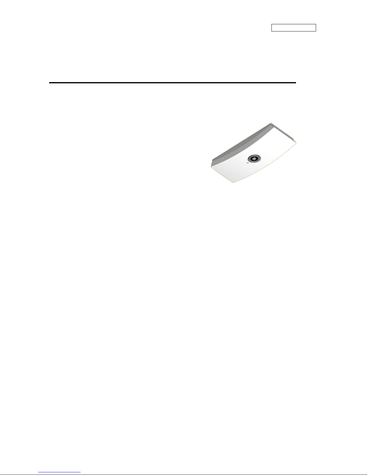
SENSOR UNIT
The sensor detects and tracks the number of people accurately using Image Recognition technology.
The sensor is installed on the ceiling of entrances and passageways of retail, public facilities etc. to capture
movements of people from above.
IN and OUT traffic data is recorded to the sensor continuously every minute and the collected data is sent to the
designated server via LAN.
Traffic data can be compiled and used as marketing information.
The sensor can cover movements of the people in a wide area and recognizes and tracks the movements of
people accurately therefore can omit people hovering near the counting area to provide an accurate traffic count.
This manual “PALOSSIE AIO (VC-1020 Sensor Unit) Installation Manual (Overseas)” explains the required
steps to install the system.
This manual is intended for the system installer.
Please follow the steps indicated in this manual when installing the sensor unit.
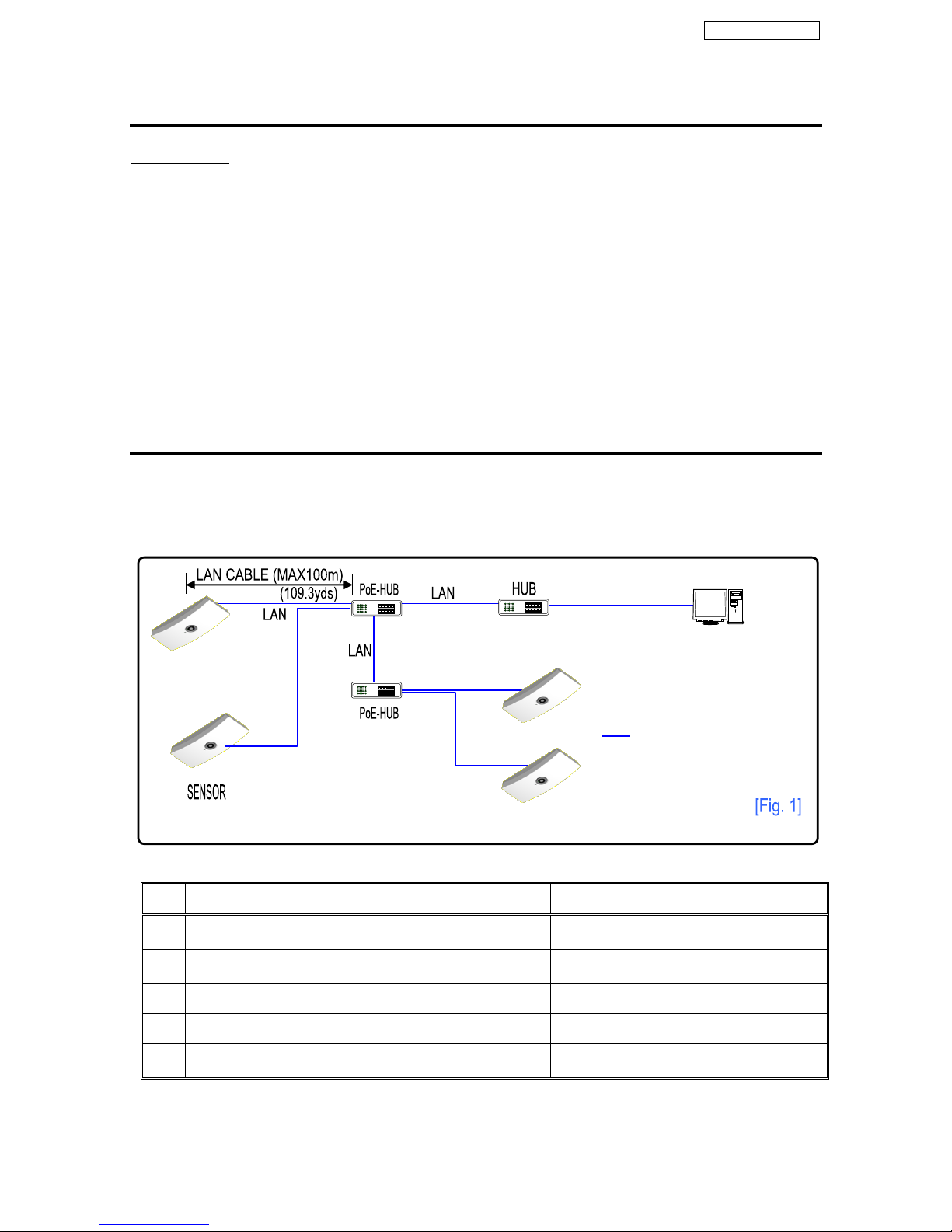
3. SYSTEM DIAGRAM / INSTALLATION WORK DETAILS
The system diagram below illustrates a general system installation of a mid-scale facility.
Details of SENSOR UNIT ->PoE HUB ->Management PC connection example. (refer to Fig. 1)
The cable length from the Sensor Unit to PoE HUB is max. 100m (109.3yds).
Work details for System Installation
Item
Work Details
Remarks
1
Signal lines, Power lines, Wire laying work according to
System Wiring Diagram
2
SENSOR UNIT ceiling mount installation and wire
connection work
3
Connect LAN cable
4
Locally purchase PoE HUB
5
Data Collection, Reporting Software Installation
Data Collection, Reporting Software
(if required)
: End Users Network
Management PC
● Data Collection Software
● Data Reporting Software
CONFIDENTIAL
2
IM-VC1020-1511-2-EN
4. SENSOR UNIT INSTALLATION AND WIRING
■ Precautions
Please keep the SENSOR lens free from any dust or debris.
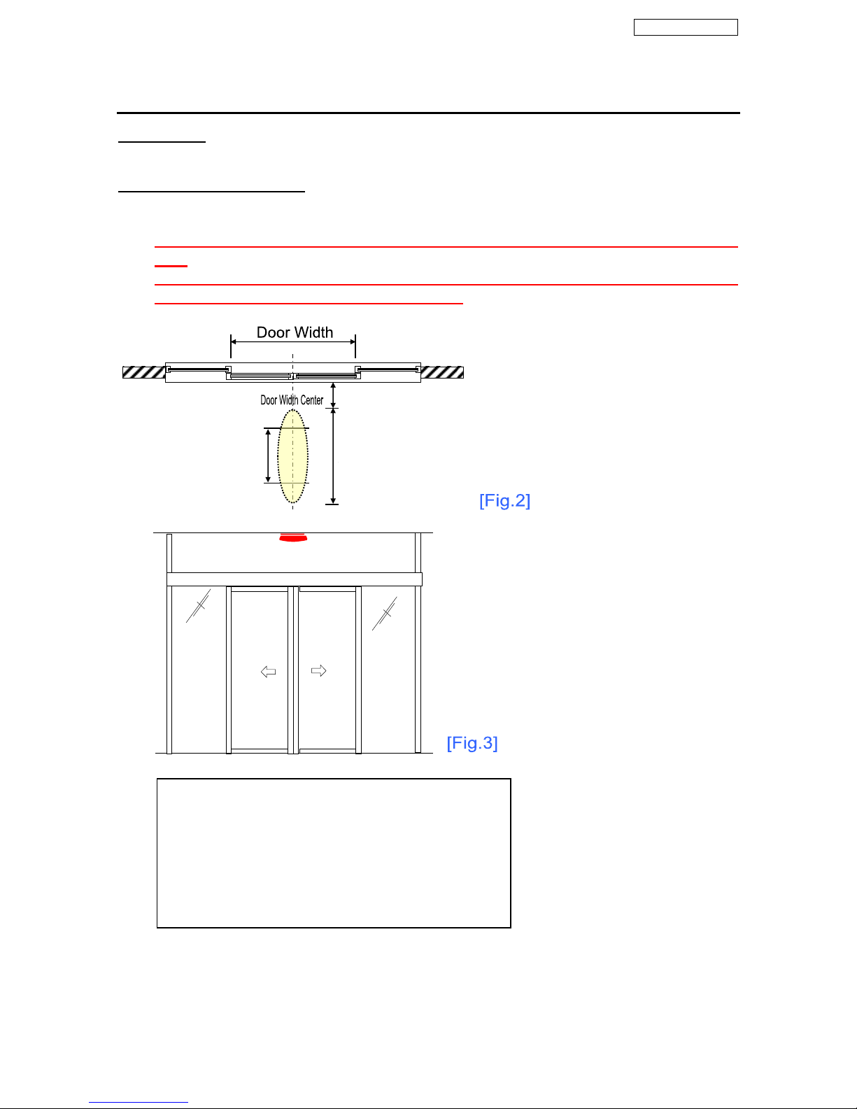
■ Installation Location Criterion
Install the SENSOR along the center of the door width, unless there is an object obstructing the center of the door
width. (Refer to Fig. 2)
1) When installing the sensor at a corridor or passageway, install the sensor in the center, between the walls or
pillars. (Refer to Fig. 3)
2) When installing 2 sensor units at 1 entrance (for wide entrances), divide the door width into two sections and
install the sensors along the center of each divided section. (Refer to Fig. 7)
Installable
500-1,400mm
(1.6-4.6 ft)
away from door
[Precautions for Installation Location]
If the sensors cannot be installed according to the criteria
above, contact and check with our staff and install according to
their directions.
Ex) Cannot install SENSOR at the door width center,
or the SENSOR cannot be installed between the
recommended 500-1400mm etc.
Cannot install within
500mm (1.6 ft) from door
Best Installation
900-1200mm
(3-3.9 ft)
away from door
CONFIDENTIAL
3
IM-VC1020-1511-2-EN
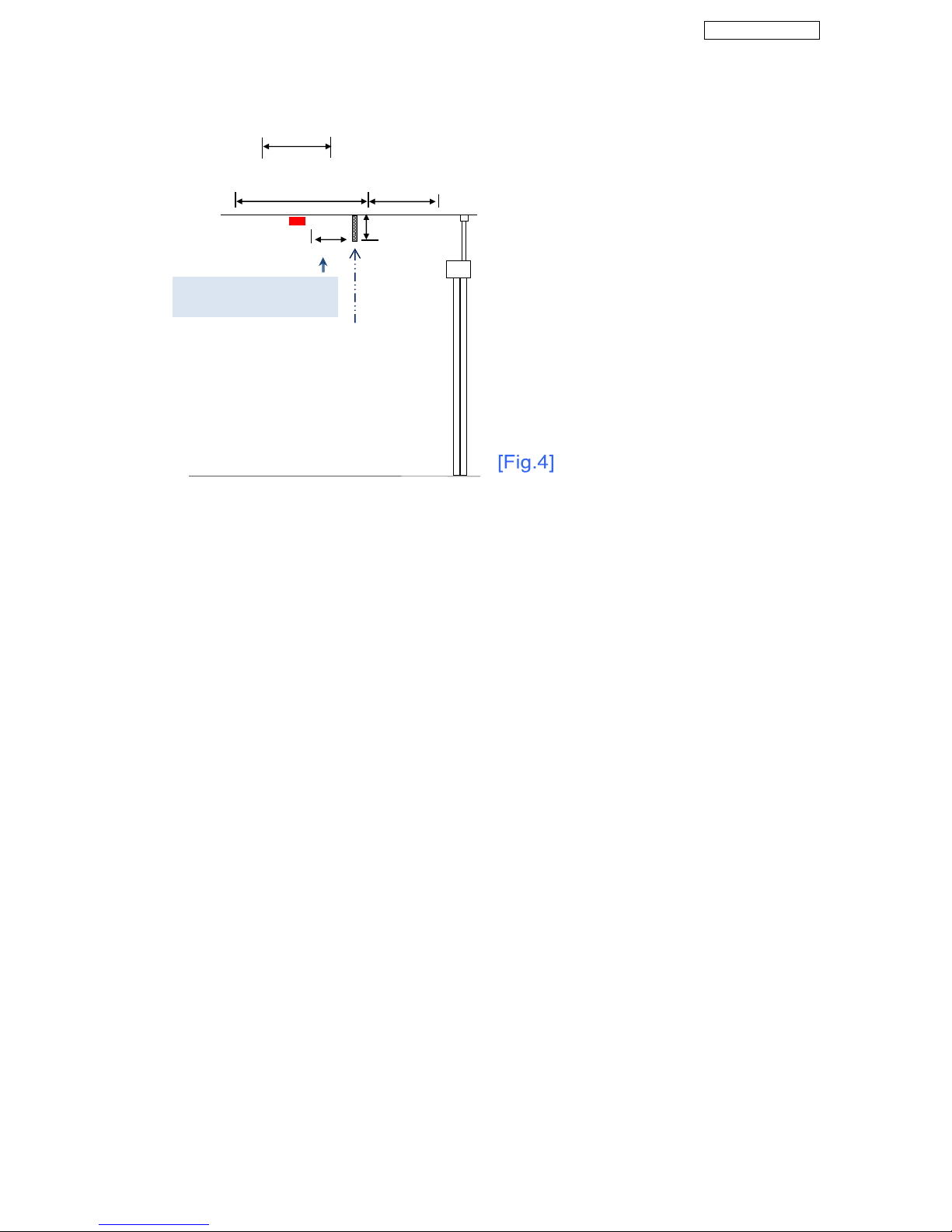
NOTE: When there is an obstructing object near
the sensor, install the sensor the “same height as
object” away from the object.
Install H mm away from
object
Obstructing Object
Best Installation
900-1,200mm (3-3.9ft)
Installable
500-1,400mm (1.6-4.6ft)
Uninstallable
within 500mm
(1.6ft)
Height Hmm
 Loading...