

Gigo Water Power 7323 Instruction Manual

What’s on
technology
15
165
pieces
#7323
models
to build
WATER
power

WATER power | Contents
Parts List ................................................................................................................. 1
Learning about Gears............................................................................................ 2-4
Learning about Chain Gears ................................................................................... 5
Tips and Tricks for Model Building .......................................................................... 6
About the Main Components of HYDRO-PNEUMATIC .......................................... 7
Notes for Assembly ..................................................................................................8
Notes for Operation ..................................................................................................9
Hydro-Pneumo ...................................................................................................... 10
Hydro-Pneumo Models (with water-recycling system)
How to Operate .................................................................................................. 11
Model 1 Cutting Machine ............................................................................. 12-13
Model 2 Grinder ............................................................................................ 14-15
Model 3 Truck ............................................................................................... 16-17
Model 4 Excavator ........................................................................................18-19
Model 5 Detective ........................................................................................ 20-21
Model 6 Tank ................................................................................................ 22-23
Model 7 Antique Car .....................................................................................24-25
Hydro-Pneumo Models (without water-recycling system)
Water-Jet Vehicles ............................................................................................. 26
Experiment ......................................................................................................... 27
Model 8 Rocket Car ..................................................................................... 28-29
Model 9 Excavator .......................................................................................30-31
Model 10 Heavy Motorbike ...........................................................................32-33
Model 11 Helicopter .....................................................................................34-35
Model 12 Detective Car ................................................................................ 36-37
Model 13 Lift .................................................................................................. 38-39
Model 14 Antique Car .................................................................................. 40-42
Model 15 Propeller Aircraft ......................................................................... 43-45
RECOMMENDATIONS
Please read these instr uctions, follow the s afety rules and keep them for r eference. We
recommend that you ma ke the models in the or der that is given. You will then be able to
understand assembly of parts and soon many more different models you wish.
WARNING TO PARENTS
• This is a toy that has been designed for children over 8 years of age. It is not suitable for children unde r 3 years of age. It cont ains small par ts that a chi ld could
swallow. It must be kept out of the reach of very young children.
• Discuss the safet y warnin gs and poss ible ris ks involved with the chil dren before
allowing them to build these models.
1
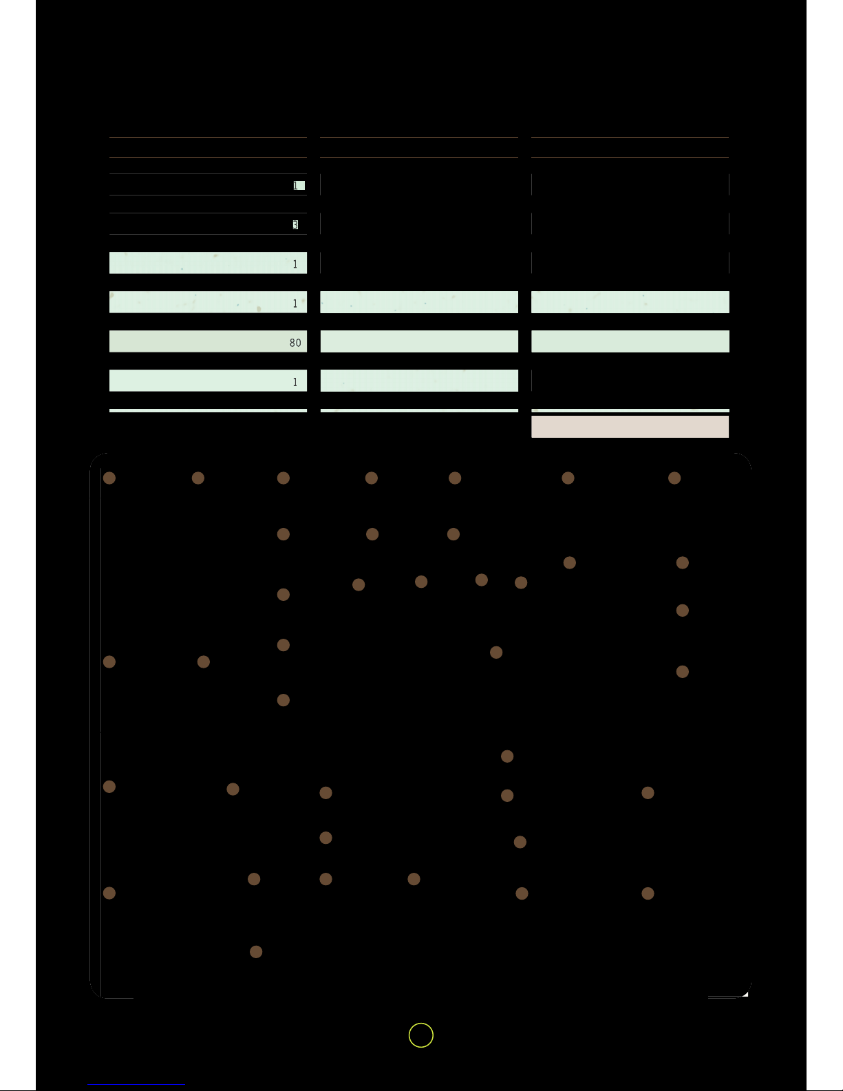
Parts List | WATER power
PCS
1
1
2
3
1
1
1
1
1
80
2
1
1
No
1
2
3
4
5
6
7
8
9
10
11
12
13
PARTS NAMES
SECURED AIR-WATER STORAGE
RECYCLED WATER STORAGE
RACING TIRE
SHORT FRAME
SECURED PUMP
AIR-WATER POWER PACK
STORAGE CAP
NOZZLE
WASHER
UNIT CHAIN
90 DEGREE CONVERTER - L
S DR. AXLE
ROD
No
14
15
16
17
18
19
20
21
22
23
24
25
26
PARTS NAMES
LONG FRAME
L DR. AXLE
XL DR. AXLE
SECURED ONE-WAY SWITCH
BENDED ROD
90 DEGREE CONVERTER - R
L SECURITY NUT
GEAR FIXING
5-HOLE ROD
DUAL ROD
S SECURITY NUT
PEG
O RING L
PCS
5
2
2
1
4
2
2
4
2
2
2
20
2
TOTAL 165
No
27
28
29
30
31
32
33
34
35
36
37
38
39
PARTS NAMES
L PULLEY
SQUARE FRAME
S CHAIN GEAR
S GEAR
M CHAIN GEAR
DOUBLE-SIDED BASE GRID
LONG ROD
PEG /AXLE REMOVER
TUBE - B 120CM
M GEAR
CAR LAUNCHER
L CHAIN GEAR
TUBE - A 200CM
PCS
2
1
2
2
2
1
1
1
1
2
1
2
1
1
2
4
5
6
7
8
9
10
11
12
15
2319
24
25
26
27
28
32
33
36
37
38 39
31
34
35
20
21
22
29
16
17
18
13
14
30
3
x 1
x 1x 1
x 1
x 1
x 1
x 1
x 1
x 1
x 1
x 1
x 1
x 1
x 1
x 1
x 1
x 5
x 2
x 2x 2
x 2
x 2
x 2x 2
x 2
x 2
x 2
x 2
x 2
x 3
x 4
x 4
x 80
x 20
x 2
x 2
x 2
x 1
x 2
2
WATER power | Learning about Gears
Every transmissio n system (gear train) contains gears. A gear i s a useful and impor tant tra nsmission c ompo nent, as it is a transmission method that applies to two shafts, or between a wheel and a shaft.
You can obs e rve the transmission of meshi ng g e a rs inside old toys or old clocks. There is a g e arbox within the
transmission system of c ars, which c ombines meshing g ears of dif ferent sizes. In this way, to change among
different speeds becomes easy.
Do you know how gears wor k? Pl ease c arefully r ead the de scr iptio ns below. You will learn the secrets of gear
trains from the world patent GIGO GEARS. The design of GIGO scientic educational building blocks ( that is
GIGO SCIENCE-TOOL KIT ) is based on the numb er of 10 and its multiples; whether o n the size of the co mponents, the distanc e betwe en the holes, o r the unique GIG O gear tooth numbe r. Therefore your child will be
a
ble to not only correctly assemble the gears, but also conveniently calculate the gear ratio or change the rotary
speed. Dif ferent from other gear desi gns adopting the number of 8 or 7 as the ir fundamental number, GIGO
gears are created with perfect designs for the use of scientic teaching, and express the care on children and
passion for scientic education.
We suggest a gradual learning with GIGO gears which starts from the basic structures to understand the combi-
nations of each component. Once you nish your practice following the examples in this instruction, and possess
t
he fundamental c oncepts of gear trains, you c an put your unlimited creativit y into action and create various
vehicles or airplanes on your own. Let’s enjoy the pleasure of creativity!
The wheel which has many tooth-shaped objects sticking out of the rim with the same size is called a “gear”. Two
gears can mesh with each other with the teeth on the rims. When a gear rotates, the other one wi l l be driven to
rotate as well. The intermeshing teeth of the two gears transmit rotation and torque.
A simple gear train uses two gears with the
same or diffe rent sizes. If one of th ese gear s is
attached to a motor o r a crank, it t akes the role
as the driver gear. The gear that is turned by
the driver gear is c alled the driven gear. Gears
are used to increase or de crease the speed or
the power of rotar y motion. The m echanism of
changing the speed o r power is call ed the gear
ratio (speed ratio).
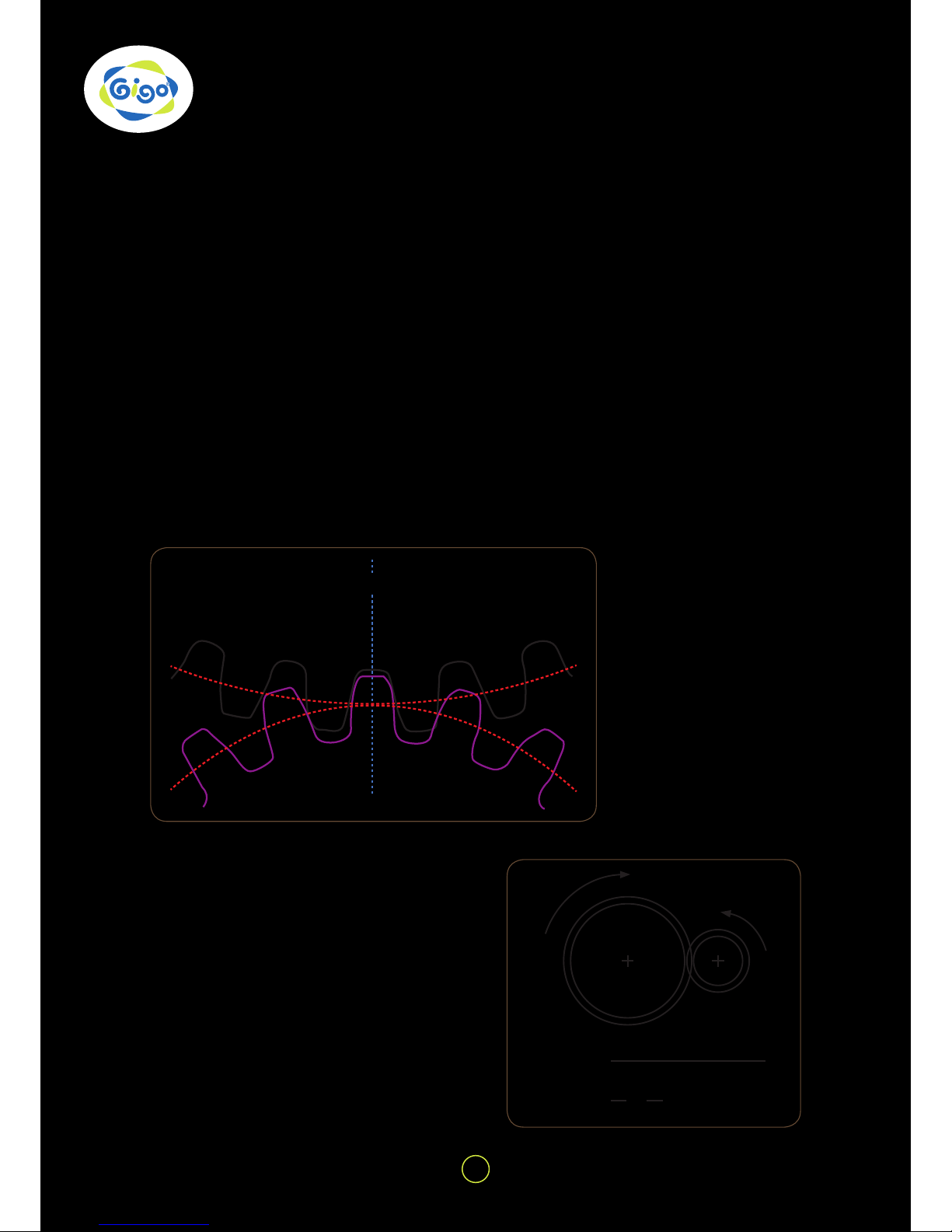
Fig. B
Illustration of gear ratio calculation
Fig. A
The intermeshing of gears
can effectively transmit rotation. The red circle represents the actual diameters of the transmission,
w
hich is called the pitch
diameter. The tting shape
of the teeth as sures the in termeshing and transmits
p
ower along the pitch.
GEAR
40 teeth
driven gear
20 teeth
driver gear
(2:1)
Velocity
ratio
=
= =
Number teeth driven gear
Number teeth driver gear
40201
2
3
160 T
20 T
40 T
60 T
80 T
The secret of GIGO des igns for gears is
to place the distanc e between each hole
based on 10 or the multiples. In Fig. E, the
distance between the centers of the two
gears is
and therefore the two gears can be
smoothly assembled or transmitted. Other sizes of GIGO gears ar e also desig ned
with the same per fect concept, and their
holes and gears can be greatly meshed
and operated with each other!
Learning about Gears | WATER power
The number of teeth betwee n th e big g ear
and small gear is different. Despite the
teeth number or size of the gears, the teeth
of the gears in the sam e gear set should
have the same size. In simple gear trains,
the driver and driven gears will rotate in
opposite directions. When a third gear
is inserted between the driver gear and
driven gear, and makes them rotate in the
same direction, it is called an idler gear.
The world patent gears designed by GIGO
come in 5 dif ferent types: 20T, 40T, 60T,
80T, and 160T, the extra large gears.
Each of GIGO gear sets contains both
spur and bevel gears. Gear s of HYDRO-
PNEUMATIC contain “Spur Gears” (gear
wheel to gear wheel) meshing in the same
plane and regulating spe ed or direct ion of
turning of the shafts and “Bevel Gears”
(the rounded off sec tions on one edge of
your gears in the set) meshed together
to change directi on at right angles to the
initial turning plane of the gears and shafts
(axles).
The tooth shape of GIGO gears shares the
same speci cation of module pitches=1.
Namely, the pitch diameter of the 20T
gears is 20mm wh ile the pitc h diameter of
the 40T gears is 40 mm. The pitch diame ters refer to the imaginary circles between
the meshed gear teeth as sh own i n Figu re
E.
Fig. D Characteristics of GIGO gear teeth
Fig. E The transmission between the pitches
during the intermesh of two gears
Fig. C GIGO Gears
= 30mmR1+R2 = +
20mm
2
40mm
2
* According to th e instruction a bove, can
you gure out how many holes there are
between a 40T and a 60T gear when they
are meshed?
R1 R2
4
WATER power | Learning about Gears
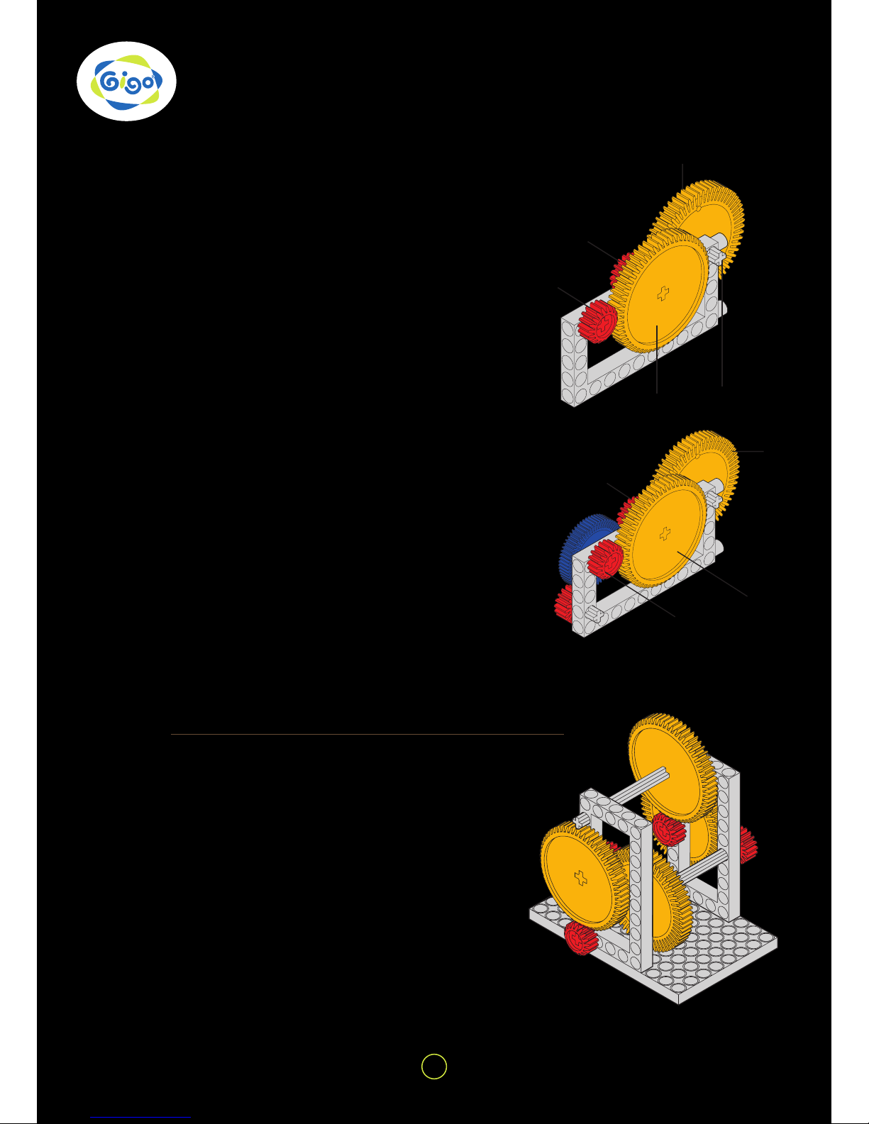
1. Use two red 20-tooth gears and two yellow
60-tooth gears to make this system.
2. How many times do you have to turn the small
gear A in order to make the sec ond large gear D
turn once?
The small gear A turning the large gear B gives a 3
to 1 ratio as you found out on the table.
The second small g ear C is directly dr iven by the
arrangement and produces another 3 to 1 ratio
with the second large gear D.
Did you nd out that you had to turn the small gear
A 9 times to turn the second large gear D once?
The overall gear ratio of the system is 9 to 1. ( A
gear ratio of 3 to 1 multiplied by another 3 to 1 =
9 to 1).
3. Add a third red 20 -tooth gear to the shor t drive
axle at (x). Why does it lock?
4. Add a blue 40-tooth and a red 20-tooth gear to the
system. Can you work out mathematically what the
gear ratio of system would be?
Count the number of turns. Were you right?
1. Th is gear box uses a c ombinati on of red 20 - tooth
gears and yellow 60-tooth gears.
There are four pairs of red 2 0 and yellow 6 0 - tooth
gears. Each pair produces a gear ratio of 3 to 1.
The overall gear ratio would th en be 3 x 3 x 3 x 3
= 81.
If gear B is turned 81 times the n gear A would turn
once.
2. If gear A c ould b e tur ned onc e then g ear B would
turn 81 times! Could you add anothe r pa i r of gears
to make a ratio of 243 to 1?
A
C
D
B
X
D
B
A
C
40
20
A
B
5
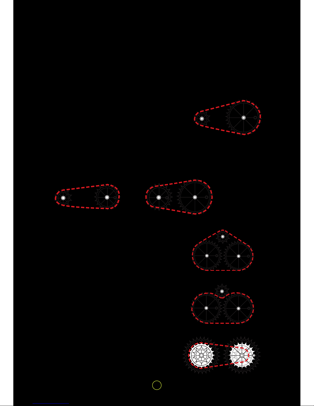
Learning about Chain Gears | WATER power
1. The power trans mis si o n of c hain g ea r s dep en ds on c h ains i n -
stead of meshing each other. The teeth of chain gears must go
with chains. The “ working” diameters of the chain gear s are
about 10mm (10-tooth), 20mm (20-tooth) and 30mm (30-tooth) .
Try to e nsure that when c onnecti ng drive chains t hey are neither too tight nor too loose so that the motion of one is transmit-
ted efciently to the other. If the lengths can not exactly t the
di
stance a litt le loos er will wor k bette r than a lit tle ti ghter, only
that the drive chains come off the chain gears. This system can
be found in normal bikes or escalators.
2. Connect a 10 -tooth chain gear to a 30 -tooth chain gear as
shown.
3. Use a pencil point, or something similar, to turn B.
Which way does A turn?
Would this be the same if A and B were two gears in mesh?
How many times would you have to turn A for B to rotate once?
The gear ratio of these two chain gears would be _ to _ ?
4. Repeat the experiment for the two other arrangements and
make a table of your results for all three.
5. Try ch aining a 10-tooth chain gear and t wo 30- tooth chain
gears together. Turn A clockwise.
What happens to B and C?
Do they turn in the same dire ction? Do they turn at the same
speed?
6. Try to chain the 10-tooth chain gear C as shown.
Turn A clockwise. What happens to B and C?
Do they turn in the same direction?
Do they turn at the same speed?
7. By connecting two sets of c hain gears tog ether three spee ds
can be obtained.
This system is widely used in tr ansmission bikes by adding a
gear shift in between.
A B
A B
A B
A B
C
A B
C
6
WATER power | Tips and Tricks for model building
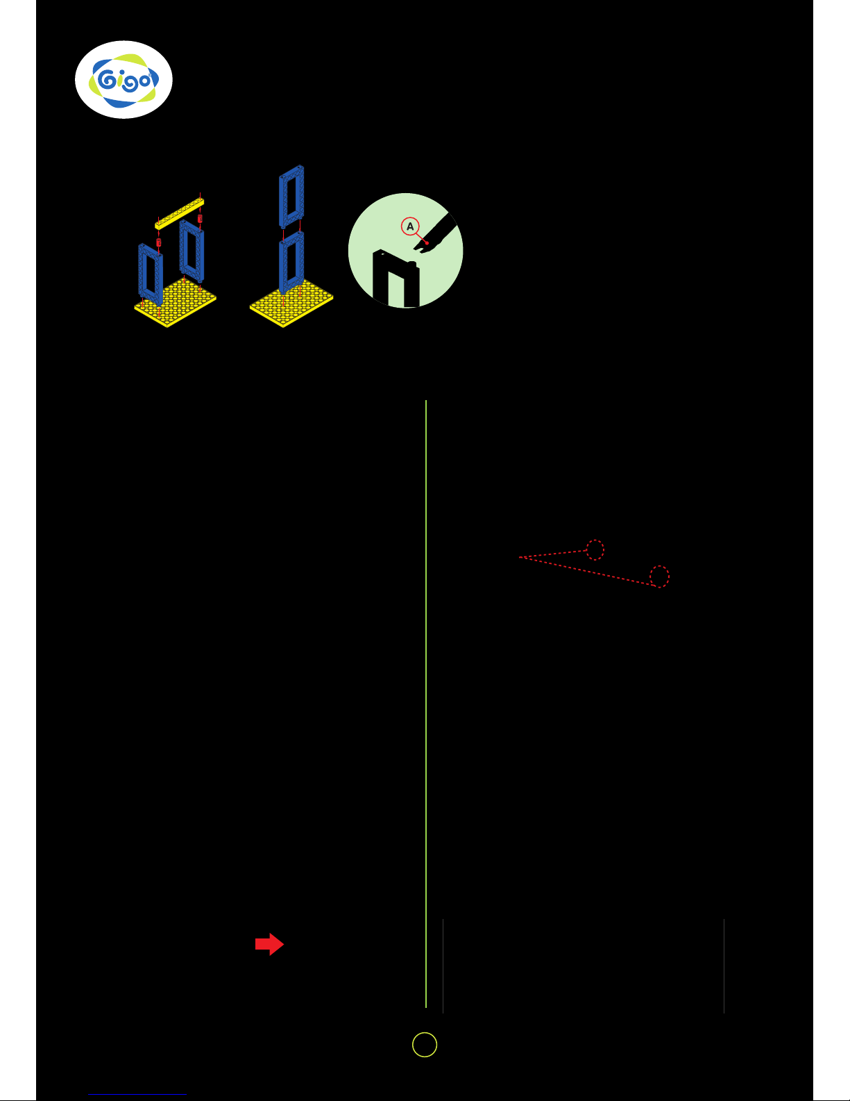
FIXING BASE GRID, RODS AND FRAMES
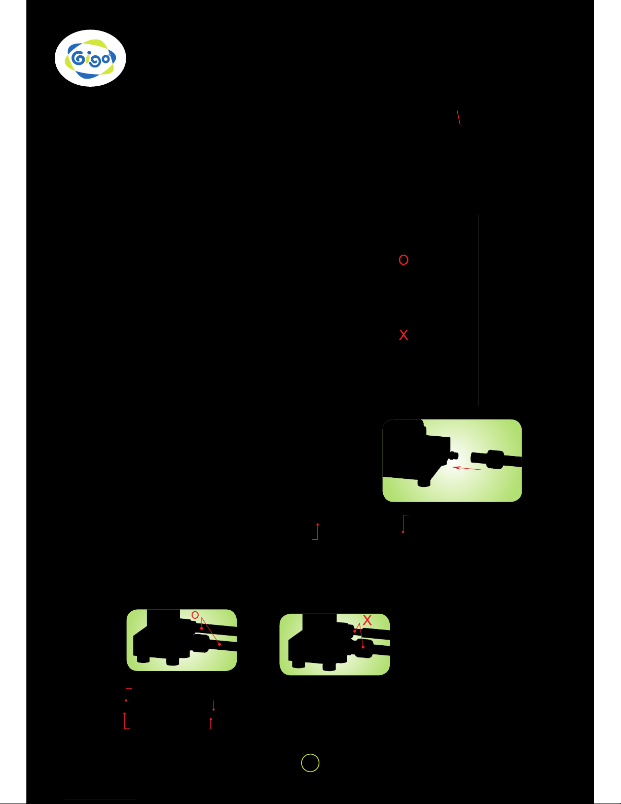
FIXI N G GEARS
1. The peg c an be used to join rods and
frames (Fig. 1).
2. Frames can be connected directly to
each other end to end (Fig. 2).
3. Using the end “A” of the peg/axle re-
mover to pull a peg off as Fig. 3 shows.
When xing gears onto the frame with a drive axle,
be sure to keep a proper space (about 1mm) between the gears and the frames. Try to turn the gear
and con rm if every gear in the gear train can turn
smoothly so that the least friction will be created and
then the most ef cient power transmission can be
expected (Fig. 4 & 5).
When you use a power pack to dri ve a whee led ve hicle, the gear whee ls should be arranged in sym metry (the holes on the two opposite chain gear
wheels must be kept in a horizontal line) and be
kept at the same driven speed, or the motor will stall
and the vehicle won’t move (Fig. 8).
Fixing gears to the frame Arranging gear wheels in symmetry
NG! (without a space)
TIP! These
two holes
must be kept
in a horizontal
line.
Gear fi xing
Gear xings are designed
to prevent a pulley or gear
from moving along the
axle, or slipping. They are
easy to be installed without removing any wheel or
axle (Fig. 6).
Meshing gears at 90°
When the two red gears
mesh with each other at 90°
the one on the drive axle
must be assembled as close
as possible to the outer end
of the axle so that the mesh
can be ensured (Fig. 9).
Use a chain gear to connect two drive axles to
lengthen when necessary (Fig. 7).
Lengthening drive axles Connecting unit chains
Ensure to get the face of each unit c hai n w he n connecting them to one another as a drive chain so
that the transmission can be done ef ciently and
smoothly (Fig. 10).
Fig. 1
Fig. 4 Fig. 5
Fig. 6
Fig. 7
Fig. 9
Fig. 10
Fig. 8
Fig. 2 Fig. 3
OK! (with a space)

7
About the main components of Hydro-Pneumatic | WATER power
Air-Water Power Pack
“A” is the entrance and “B” is the exit. Air
and water enter the power pack throug h the
entrance to strike the water wheel directly
and drive the mechanism behind it. Then
the water ows back to the Recycled Water
Storage through the exit for repeated use.
Secured Pump
“A” is the entrance and “B”
is the exit. The water in the
Recycled Water Storage is
driven by the Secured Pump
to come into the Air-Water
Storage.
When the pump rod is pull ed
up, air and water will come
into the Secured Pump
through the entrance and
then go out to the Air-Water Storage through the exit
w
hen the pump rod is pushed
down.
Recycled Water Storage
Secured Air-Water Storage
“A” is the entrance
and “B” is the exit. Air
and water in the Secured Recycled Water Storage come into
the Air-Water Storage
through the entrance
and go out through the
exit.
Secured One-Way
Switch
“A” is the entrance and
“B” is the exit. W hen the
switch rod is in the middle, the exit is closed, and
air and water come into
One-Way Switch. When
the switch rod is turned to
the side of the entrance,
the exit is opened and the
air and water ow out.
Exit
Hose B Entrance
Hose A Entrance
Water Wheel Mechanism
Front Back
8
WATER power | Notes for assembly
1. NOTES FOR ASSEMBLY:
• Insert a 9.5 cm long Tube A into
the protrudent hole on the reverse side of the lid of the Recy cled Water Storage, and cut its
the other end on the bias (Fig.
11). To attach the bias -c ut end to
the inside bottom of t he storage
so that water will easily enter the
hose when pumping.
• The lengths of hoses for the mod-
els given in this guide are for reference only. Be sure not to make
the hoses too tight no r tw isted or
pressed (Fig. 12) in connection so
that water can go through them
smoothly.
• Put a Security Nut through a hose
and screw it completely when
connecting the hose to a secured
basic part (Fig. 13 & 14).
• Use an L Securit y Nut for Tube
A, and an S Security Nut for Tube
B. The hoses might become stubborn and easily come off the connected part after repeated use.
The solution is to cut off the stubborn end about 1-1.5cm long. Be
sure to wipe the conne cted part
dry with tissue paper before the
refreshed hose is used again.
• The cut hoses c an be repeatedl y
used for different models.
Fig. 11
Fig. 12
Fig. 14
Fig. 13
cut on
the bias
S Security Nut
L Security Nut
No Security Nut
L Security Nut
Tube A
Tube B
Tube B
Tube A

9
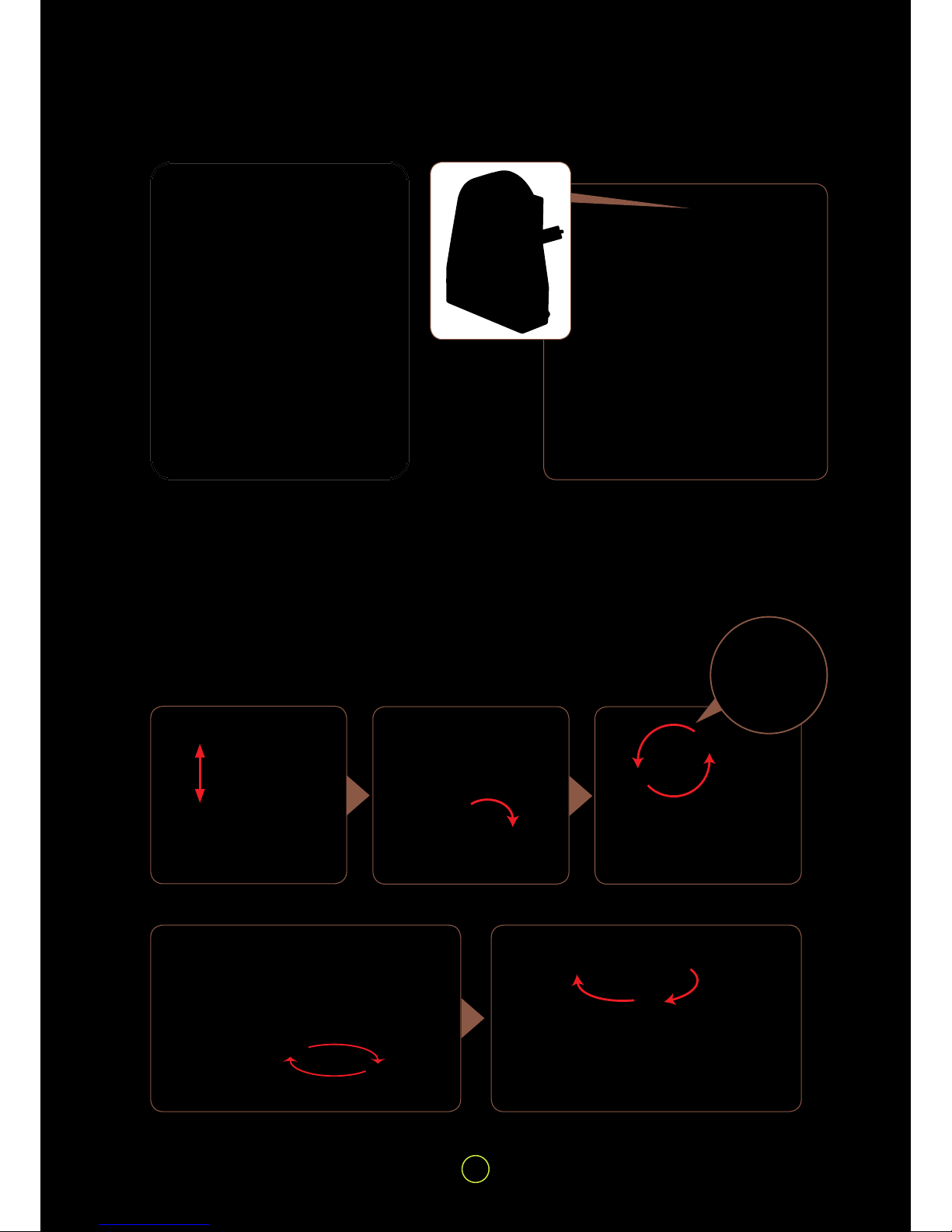
Notes for operation | WATER power
Fig. 15
Fig. 16
Fig. 17
Fig. 18
2.N OT ES FOR OPERATION:
• Check if all the hoses are xed to the
right positions before pumping.
• Check if all Switch Rods are put in
the middle of the Swi tches (i.e. in a
closed condition as Fig. 16 shows)
before pumping so that the pu mped
air/water won’t escape.
• The Switch Rod should be xed a lit-
tle tight so that air/ water leaking c an
b
e avoided. Don’t hesitate if it needs
some strength to move it.
• Check if the Air/Water Storage is
screwed to the end (Fig. 15).
• Move the Pump from the model to the
tabletop whenever you pump it, and
put it back after you nish pumping
(Fig. 17).
• The rst 10 pumping is for pushing
the water from the Recycled Water
Storage to the Secured Air-Water
Storage. Try to hold the pump rod up
for 2-3 seconds before you push it
down so that the most water c an be
driven into the pump cylinder in e ach
pumping (Fig. 18).
• Pump no more or less th en 5 0 t i me s.
If pumping over 50 times, the basic
parts might b e under too muc h pres
sure and become dama ged. On the
c
ontrary, if pumping less than 50
times, the power might be too weak to
lead to a smooth operation. The more
the air is pumped into the basic p ar t,
the bigger the air pressure and the air
power are caused (PV=nRT).
• Don’t pull off any hose eit her during
the operation or b efore all the water
gets back to the Recycled Water Storage. Ontherwise, the water stream
w
ill spurt from the hose and might
hurt you or spoil the surroundings.
• Once if hoses come off during the
operation, please tu rn off the switch
by shifting the switc h rod back to t he
middle to stop the spur t of the water,
and wipe the hose opening dry before
rexing it on.
• Use the secured One-Way Switch
to release the air/ water left in the
Air-Water Storage before you put the
models away.
Screw Air/Water
Storage to the end.
In the Close
Condition

10
WATER power | Hydro-Pneumo
PRINCIPLES:
Each time as the Secured Pump drives the water from the Recycled Water Storage into the Secured AirWater Storage, the water shall squeeze upward the enti re air inside the Secured Ai r-Water Storage. Air is a
compressible uid, in other words, the volume of air can be reduced by compressing, whereas water cannot.
When more and more water is added into the Secured Air-Water Storage, the water shall occupy more and more
capacity. Since the space within the Secured Air-Water Storage is limite d, the water w hic h eventually oc c up ie s
more and more space compresses the air inside the Secured Air-Water Storage. As a result the pressure inside
is exceedingly higher than th e air out si de t he S ec ure d A ir-Water Storage. This hi gh -pressurized air pushes the
entire water within the Sec ured A i r-Water Storage, where the water sh oves the latera l side s of the sto rag e and
attempt to escape to recover pressure equilibrium.
After the air pump draws water into the Secured Air-Water Storage and is then pumped for another 40 times, more
air is pumped into the remaining xed space occupied by water, and thus the inside air pressure is even higher.
These phenomena include many physical principles:
1. Water is incompressible, whereas air is compressible.
2. Boyle’s law:
For a xed amount of gas kept at a xed temperature, the product of the volume and pressure is constant.
(P1 · V1 = P2 · V2) (P1 : P2. = V2 : V1)
As more air is pressed inside the xed volume, the air pressure shall rise.
3. Pascal’s principle, also called Pascal’s Law, is a term in uid (gas or liquid) mechanics. It indicates pressure
variation occurred with a part of the static uid within the closed container, and transfers to every part of the
uid and to a part of the container wall without any loss.
How much energy is stored within the Secured Air-Water Storage?
According to th e experime nt, when the S ecured Pum p draws water into the Sec ured A ir-Water Storage and is
then pumped for another 40 times, the value is approximately 3.5kg/cm
2
EXPERIMENT
1. Use a pressure gauge not included in this set for inspection.
2. At initial state the value of the pressure gauge is zero.
3. Pump the water fr om the Recycl ed Water Storag e into the Sec ured Air-
Water Storage. By evenly pressing the Secured Pump for about 10 times.
4. At this point, the pressure is approximately 0.9kg/cm
2
.
5. Each time as the Secured Pump drives the water from the Recycled Water
Storage into the Secured Air-Water Storage, the water shall squeeze
upward the entire air inside the Secured Air-Water Storage. Air is a
compressible uid, in other words, the volume of air can be reduced by
compressing, whereas water cannot. When more and more water is a dded
into the Secured Air-Water Storage, the water shall occupy more and more
capacity. Since the space within the Secured Air-Water Storage is limited,
the water whic h eventually oc cupies m ore and mor e space co mpresse s
the air insid e the Secured Air-Water S torage. As a result the p ressure
inside is exce edingly higher t han the air outsid e the Secured A ir-Water
Storage.
6. Pump the Secured Pump another 40 times.
7. Pumping steadily to pe r fo r m a co mpl eted s tro ke as po ssi ble a s you c an,
the value is approximately 3.5kg/cm
2.
8. When more air is pumped into the remaining xed space, the air pressure
inside is even higher.
11
Hydro-Pneumo Models (with water-recyling system) | WATER power
1 atmospheric pressure (atm)
= 76 cm-Hg
= 76*13.6 (density of mercury)
= 1033.6 cm-Hg = 10.336 m-Hg
3.5kg/cm
2
compressed air is equal to
3.4 atm. If it is compare d to potential energy, 1 atmospheric pressure
(atm) = 10.336m-Hg, 3.5kg/cm2 = 35
m height of water column pressure
(it can be compar ed to the height of
a 10-story building). Therefore the
created energy via air pum ping and
stored within the pressure storage
tank, can push and r un your various
unique assembled models.
HOW TO OPERATE
1. Pump the Secu red Pum p abo ut 10 times to get all water f rom Water-Recycl ed S tora ge to Se c ure d A ir-Water
Storage and keep pumping another 40 times to compress the air in the Secured Air-Water Storage.
2. Then turn the rod of the Secured One-Way Switch to open it.
3. The released water will jet out to strike the blades of the water wheel to activate the
Air-Water Power Pack and drive the mechanism behind it, and then ows back through the
exit to the Recycled Water Storage for repeated use.
Step 1 Pump 50 times. Step 2 Turn on the switch.
Step 3 To activate the Air-
Water Power Pack.
To drive the mechanism behind it. The model works!
Back
View
The exit
Front
View
The entrance

12
WATER power | MODEL 1 Cutting Machine
Notes for Assembly
Parts Needed
x 36
x 16
x 1
x 1
x 1
x 1
x 1
x 1
x 1
x 1
x 1
x 1 x 1
x 1
x 1 x 1
x 1
x 1
x 2x 2x 2
x 2
x 2
x 2
x 2 x 2
x 3
x 4
x 4
Cutting
Machine
1. The g ear s sho uld b e mes hed w ith e ach ot he r well in
order to operate smoothly.
2. Note that the chain gears are to be aligned in order for
the chain to operate smoothly.
3. Cut Tube A and Tube B to get t he tubes i n follow ing
lengths for this model.
Tube A : 9.5cm x1, 30cm x 1, 37cm x 1, 44cm x 1
Tube B : 25cm x 1, 35cm x 1
Tube BTube A
1 2
3
1
3 42
5 7
9 11
6 8
10

13
MODEL 1 Cutting Machine | WATER power
12 1413
15
19
20 21 22
16
17 18
23 24
25
26
27 28
29 30
31 32
Completed
 Loading...