

Giggo GT00100 User Manual

USER’S MANUAL
ITEM# GT00100
INDIAN MOTORCYCLE (6V)
Trademark of Indian Motorcycle International LLC. Used under license.
Illustrations are representative only. Design and style may vary.
Carefully read this manual before use and keep for future reference.
Customer Service:
1-855-GIGGOTY (1-855-444-4689)
1 customerservice@giggotoys.com
ASSEMBLY INSTRUCTIONS
WARNING:
Assembly must be performed by an adult. Improper assembly may result in serious operator
injury or death. Do not allow children to play with the parts prior to assembly, the plastic bag or
packing material covering the vehicle. Injury may occur. Small parts are a choking hazard!
Plastic bags are suffocation risk– discard plastic bags immediately upon opening.
TECHNICAL DATA
Speed: 2 MPH, 2.5 km/hr
Battery: 6V4AH sealed dry cell battery
Time for charging: 8 – 12 hours
Ages: 2 – 4 years old
Load Max capacity: 55 pounds/ 25 kgs
Charger: Input 120 – 240 Volt, depending on local voltage; Output – DC 6V500mA or
7.5V500mA
Life of Battery: Approximately 200 hours, 300 charges.
Working time: About 40 to 90 minutes, depending on weight of the rider, road surface and
length of time prior to last battery charging.
Functions: Forward, backward, stop, working headlight and tail light, engine sound.
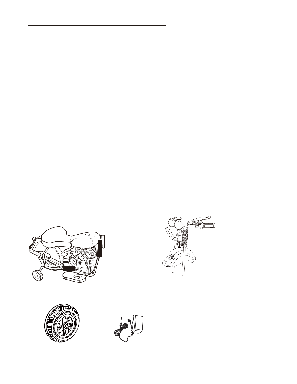
PARTS LIST
Vehicle Body Handlebar Assembly
Cap bushings
Front Wheel Charger Hardware Bag
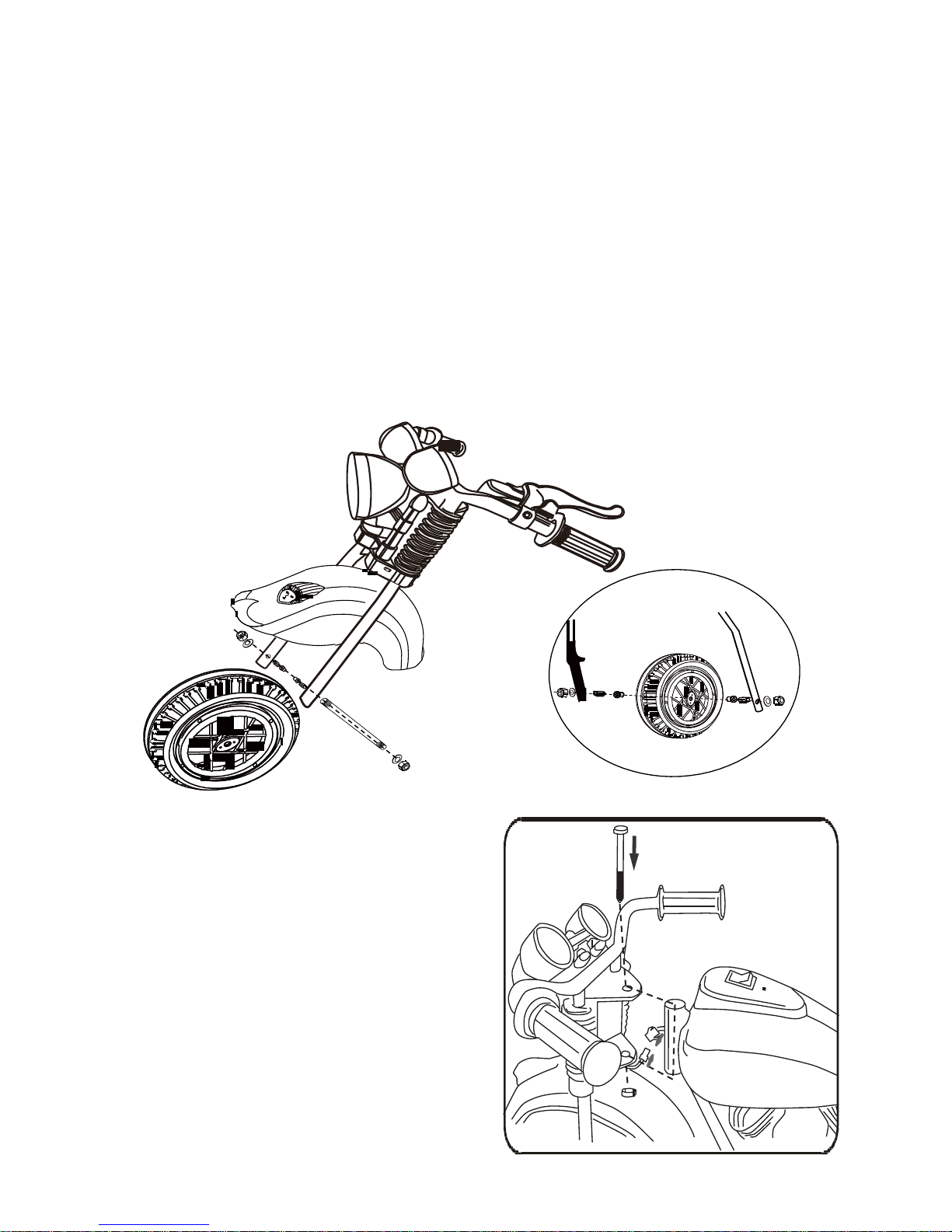
VEHICLE ASSEMBLY
Tools needed (not included): Phillips head screwdriver and two (2) adjustable
wrenches. Some parts of this vehicle may come partially assembled.
1. Insert a cap bushing into each side of the axle hole at the center of the front wheel.
Position front wheel between the forked legs of the handlebar assembly. Insert axle
through one fork leg placing a round spacer between the fork leg and the cap bushing
in the front wheel. (See illustration).
2. Push the axle through the front wheel placing another spacer on the opposite side of
the wheel prior to pushing the axle through the opposite fork. Add a washer to both
sides of the axle and then hand-tighten a nut on each end of axle. Now, using two (2)
adjustable wrenches, hold one nut as you tighten the other. Reverse this process to
tighten the nut on opposite side.
3. Remove the steering rod and nut from
the handle bar assembly. (See
illustration.) Line up the holes in the
handle bar assembly with the holes in
the vehicle body and insert the steering
rod. Attach the nut at the bottom.
Tighten the steering rod and nut with
two (2) adjustable wrenches.
4. Connect the two plugs for the headlight.
(See illustration)
 Loading...