

GigE FC11000GE, FS11000GE Instruction Manual

K09821;1/37
- 1 -
Video Camera
Instruction Manual
GigE Vision compliant
11 Megapixel Progressive Scan Monochrome/Color Camera
FC11000GE
FS11000GE
● We greatly appreciate your confidence choosing our TAKEX CCD Video Camera.
● Please read this manual and the attached guarantee certificate carefully and manage the camera properly.
Keep this manual at hand and reread it whenever you are uncertain about the operation.
Table of Contents
1. Features ······························································································ 3
2. Outline ································································································· 3
3. Description of Each Component ······························································· 4
4. How to Operate ····················································································· 6
5. Various Settings ··················································································· 11
6. How to Change Settings········································································· 14
7. Serial Communication Command ····························································· 22
8. Timing Chart ························································································ 29
9. Image Display Software and API terms ····················································· 34
10. Notes ································································································· 36
11. Specifications ······················································································· 37
12. External Dimensions ············································································· 37
TAKENAKA SYSTEM CO., LTD
Document No.: K09821
FX11000GE Instruction Manual (4th version)

K09821;2/37
- 2 -
[History of revision]
Version Content of change Description Date
Document
No.
Remark
1
st
version
2009-04-08 K09408
FC11000GE
FS11000GE
2nd version K09531
3rd version K09713
4th version K09821
Description of special remarks used in this manual
(Note) ················ Particulars which require the user’s attention are explained.
(!) ················ Particulars which require the user’s close attention in terms of comparison with the conventional
products are explained.
[Terminology] ················ Terms specifically defined for the purpose of describing the operation of this camera are explained.
[Explanation] ················ Particulars for which details may be needed for user’s understanding of the operation of this
camera are explained.
K09821;3/37
- 3 -
1. Features
●
FC11000GE/FS11000GE is a full frame shutter monochrome(FC11000GE)/color(FS11000GE) camera incorporated
with 11-megapixel, diagonal 43mm-size CCD image sensor .
●
A full frame shutter image can be obtained at a rate of 5 frames per second (in DUAL mode).
●
Gigabit Ethernet is adopted as the output interface of image signal.
●
Image signal can be output at 12/10/8-bit resolution.
●
The set values of the camera can be externally controlled with the use of the serial communication via Ethernet.
●
The character information of the current setting status of the camera can be superimposed over the captured image on
the screen. (On Screen Display function)
●
The monitoring function for measuring the internal temperature of the camera.
●
The asynchronous shutter is applicable both in the preset shutter mode and the pulse width control mode.
●
The camera is designed so that the strobe signal can be output even in the continuous shutter mode, and this
contributes to the power saving for LED lighting and others as well as the reduction of smear.
●
The ID information set by the user for each camera can be saved and read out whenever necessary ( via serial
communication link).
●
It is equipped with correction function that automatically reduces the difference between right image and left image.
●
FS11000GE is a color camera(Bayer, RAW output).
※
FS11000GE is not equipped with IR cut filter. If it has the coloring problem by the effect of infrared, use the camera with the
IR cut filter placing in front of lens.
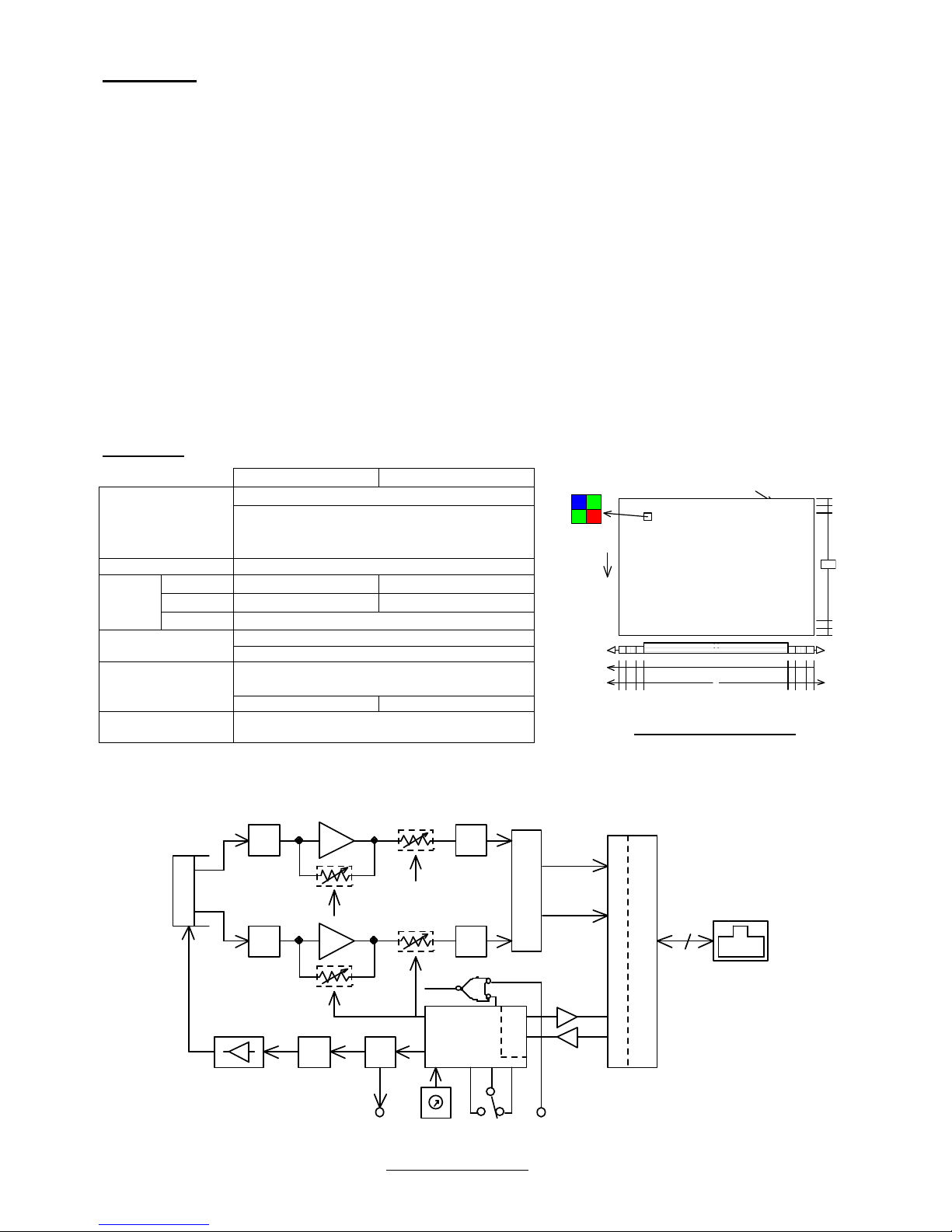
2. Outline
CCD
DRIVER
P LDT G
CP U
A /D
( OFF SET )
Preamplifier
(GA IN)
UA RT
S /H
SYNC
V ini t
C a me r a Li n k I /F
G ig a bi t E th e rn et
IP ENG IN E
R X D
T X D
V i n i t 1S T R B
M O D E , EX P U D - S W
S /H A /D
( OFF SET
+ OFF SET _B)
(GA IN
+GA IN_ B)
PL D
DUA L&S ING LE
DUA L
R J -4 5 Con n ec to r
Gi g E I/F
12/10/8 bit
DUAL out SINGLE out
Image sensor
Imaging area size
Number of pixels
Pixel size
CCD Image sensor: Monochrome/Color
36.07mm
×
24.05mm (Diagonal 43mm)
4008(H)
×
2672(V)
9.0μm(H) × 9.0μm(V)
Effective pixels 10.7 megapixels
Read out
scanning
Horizontal
14.1 KHz 7.5 KHz
Vertical
5.1 Hz 2.7 Hz
Clock
32.50 MHz
Electronic shutter
1/2000 to 1/5 second
(Continuous shutter and asynchronous shutter)
Video output signal
Digital 12/10/8 bit
Gigabit Ethernet interface(GigE Vision compliant)
2Tap 1Tap
Scanning mode
Normal scanning for all pixels
Double speed scanning
OB(Optical black)
Ef fe ct i ve imag e p i ck u p ar e a
40 08 x 26 72
V
SIN GL E
VID E O L
4008
20
1 7
1 6
2672
H
1284 19 413
VI DE O R
2004 2004
8
Output
DUA L
or
BRGG
C olo r
c odi ng
Fig.2-1 CCD architecture
Fig.2-2 Block diagram
K09821;4/37
- 4 -
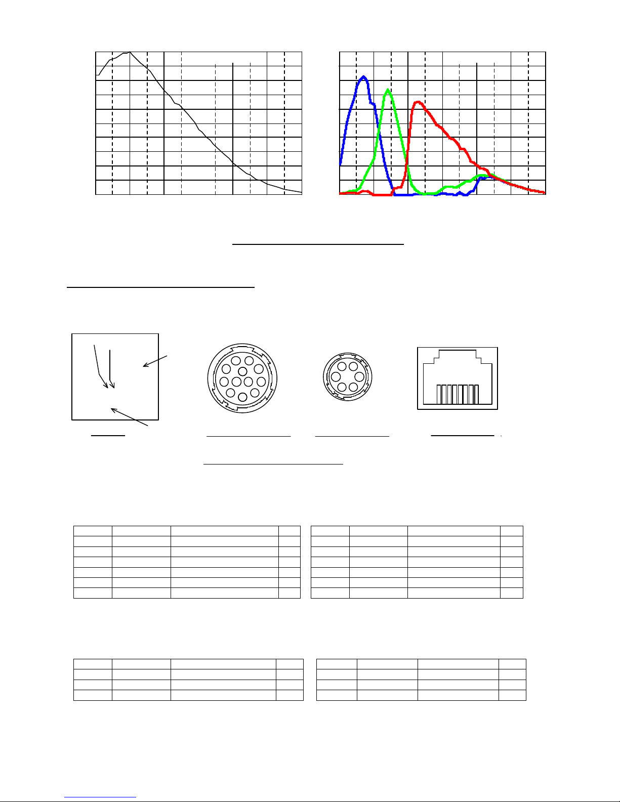
1.0
0.9
0.8
0.7
0.6
0.5
0.4
0.3
0.2
0.1
0.0
500400 600 700 800 900 1000
(Typ ica l v alu e )
FC11000GE
1.0
0.9
0.8
0.7
0.6
0.5
0.4
0.3
0.2
0.1
0.0
500400 600 700 800 900 1000
Wavele ngth
(nm)
FS11000GE
( Note)T he charac ter ist ics o f l ens ,lumin ous so urce e tc . are lef t o ut of con sid erati on.
R e lat i v e s e ns i t i v it y
R e l a ti v e s en s it i vit y
Wavele ngth
(nm)
(Ty pic al val ue )
3. Description of Each Component
(3-1) Description of rear panel of camera
Panel to set up operation mode, electronic shutter speed and other parameters and to connect each output connector → Refer to
the diagram below.
POW ER
EX P.
M ODE
U
D
LE NS
1 0
11 12
9
8
7
6
5
4
3
2
1
1
2
34
5
6
Ca m er a c on n ector (P OW E R ) I ris c on nec tor( L EN S )
R ear p a nel
Ope ration ind ica tor
Link sp eed indica tor
L ink sta tus in dicator
RJ-45 LAN Connector
8 7 6 5 4 3 2 1
LA N co nne cto r
(3-2) Camera connector (POWER) (
HRS HR10A-10R-12PB
)
The pin arrangement of the Camera connector (12 pins) and the
signals assigned to those pins are shown in the following table:
Pin No. Signal name
Description I/O
Pin No. Signal name
Description I/O
1 GND (0V) Power ground
7 IC
2 +12VDC DC power input
(In)
8 GND Signal ground
3 GND Signal ground
9 IC
4 IC
10 GND Signal ground
5 GND Signal ground
11 STRB Strobe signal output
Out
6 Vinit1 Input for external trigger
In
12 GND Signal ground
* Do not assign any signals to the IC pins because they are occupied internally.
(3-3) Iris connector (LENS) (
HRS HR10A-7R-6SB
)
The pin arrangement of the Iris connector (6 pins) and the signals
assigned to those pins are shown in the following table:
Pin No. Signal name
Description I/O
Pin No. Signal name
Description I/O
1 NC
7 +12VDC DC power
(Out)
2 GND (0V) Power ground
(Out)
8 NC
3 IRIS Iris output
Out
9 NC
(Note) ”IRIS” is the false image signal output exclusively used for controlling the image signal input type-Auto iris lens
It is not possible to take out the normal image signal from this pin terminal.
Fig.2-3 Typical sensitivity characteristic
Fig.3-1 Connectors on rear panel

K09821;5/37
- 5 -
(3-4) Mode switch (MODE)
The Operation mode and Gain can be set by manipulating Mode switch and UP/DOWN switch.
(3-5) Shutter switch (EXP.)
The shutter speed (shutter exposure time) can be set by manipulating Shutter switch.
(3-6) UP/DOWN switch (U-D)
The Operation mode and Gain can be set by manipulating Mode switch and UP/DOWN switch.
(3-7) LAN connector (Standard type RJ-45 connector)
This is the LAN connector (RJ-45 type) conforming to Gigabit Ethernet interface (1000BASE-T/IEEE802.3ab).
It is connected with the LAN connector of PC using standard LAN cable(CAT-5e or CAT-6) conforming to Gigabit Ethernet.
[Pin arrangement of LAN connector (RJ-45)]
Pin No. Signal name Description I/O
1 TP0+ Twisted pair 0 (+) In/Out
2 TP0- Twisted pair 0 (-) In/Out
3 TP1+ Twisted pair 1 (+) In/Out
4 TP2+ Twisted pair 2 (+) In/Out
5 TP2- Twisted pair 2 (-) In/Out
6 TP1- Twisted pair 1 (-) In/Out
7 TP3+ Twisted pair 3 (+) In/Out
8 TP3- Twisted pair 3 (-) In/Out
When using this equipment on a place subject to constant vibration or impact, it is recommended to employ a screw lock type
LAN cable. Firmly screw a locking screw into a connector fixing screw hole when using a screw lock type cable.
(3-4) Display LED
Three indicator LEDs are laid on the rear panel
・Operation indicator LED (POW: Three colors: green/red/orange)
It lights up (or brinks ) to indicate that the camera is powered.
When the camera is set in the asynchronous shutter mode, It lights up in red
in response to the input of the external trigger signal.
・Link speed indicator LED (SPD: orange)
It lights up in orange to indicate that the camera is connected to LAN port (LAN card) or HUB of Gigabit Ethernet
Interface (1000BASE-T).
It turns off when the camera is connected to LAN port (100BASE-T, 10BASE-T) of which communication speed is lower than
1000BASE-T or when the camera is connected to nothing.
・Link status indicator LED (LINK: green)
It lights up when the camera is connected to the other LAN port via Ethernet and the data-access is running as well.
Name
Color OFF ON Blinking
SPD Orange Disconnected from LAN
or Connecting at 10Mbps/100Mbps
Connecting at 1000Mbps -
LINK Green Disconnected from LAN Connected to LAN Data accessing

K09821;6/37
- 6 -
4. How to Operate
(4-1) Connection method
● Connection
Refer to the connection example between the camera and
peripheral devices (Fig. 4-1).
(1) Remove the cover of the lens attachment section and
attach a lens (option).
(2) Connect the camera head to a power supply unit(option) with a
camera cable (option).
The maximum allowable length for camera cable is 10 m.
(3) Connect the LAN connector on the rear of the camera to the LAN
connector of PC through LAN cable(Cat-5e or greater).
The maximum allowable length for a standard LAN cable is 100m.
Also, the maximum allowable length for a hi-flex LAN cable is 30m.
(4) Turn on the power switch of the camera after
confirming the connecting condition.
In 1 or 2 seconds after the power is turned on,
the operation indicator LED on the rear panel of
the camera changes from orange to green to show
that the camera is in operation.
(5) Set the camera operation modes in accordance
with the setting instructions for the operation
modes and the shutter speed that are described
in another section.
(Note) The maximum allowable lengths of the camera cable and the LAN cable aforementioned are not for the purpose of
guaranteeing the operation of the camera. Proper image signals may not be obtained even when the cables are
within the allowable ranges, depending on the installation conditions of the camera, cables in use and others.
Especially for a camera cable (Power cable), the voltage of the terminal end on camera side is required to be within
a voltage range of the specification (12V±10%) with the camera being connected.
(Note) As the LAN card, use a separately recommended product or a LAN port equipped with recommended Ethernet
controller(PHY).
[Important]
(Note) Make sure to turn off the power switch of the camera before connecting or disconnecting the camera cable.
If the cable is connected or disconnected while the power is supplied, troubles may be caused.
(Note) Make sure to turn off the camera and connected devices in advance when the camera is connected.
(Note) When a power supply unit other than Takenaka’s camera power supply units that are separately sold is used, make sure
that it complies with the following rated specifications:
Power supply voltage: DC12V±10%
Current capacity: 1.2A or over (recommended value)
Take into consideration the fact that transient current of about 1.8A flows when power is applied.
Ripple voltage: 50mVp-p or less (recommended value)
Connector: 12 pin connector 1 pin (GND), 2 pin (+12VDC)
(Note) Some power supply units other than TAKENAKA’s products have different layout of power connection pins. Make sure to
check the compatibility of the power supply unit and the camera connection pins in advance.
Carefully note that any failure associated with power application to out-of-
specification pins and others is subject to
charged repair.
(4-2) Input of Vinit signal (asynchronous trigger signal)
● How to input Vinit signal
If the camera is used in the asynchronous shutter mode, the Vinit signal (asynchronous trigger signal) must be input
from the user unit.
The Vinit signal is input from Pin (6) of the “POWER” connector (12 pin connector) on the rear of the camera.
If the camera is connected to the power supply unit PU100 with a Takenaka’s 12W series cable, connect the Vinit
signal (asynchronous trigger signal) to the trigger input terminal of the power supply unit (PU100).
(Note) Though the asynchronous trigger signal can be given by serial communication command via GigE interface, it
is not suitable for real-time image capturing as it gets delayed following packet forwarding.
(Note) When the camera is in OSD menu displaying status (when the operation indicator LED blinks in green), periodic
trigger signal continues to be supplied from internal CPU so that OSD display is updated on regular basis.
In this state, the external trigger signal (Vint) can not be accepted.
Turn the OSD menu to hidden status to make Vint signal input effective.
Fig. 4-1. Connection example between
camera and peripheral devices
Computer
LAN card
(LAN portト)
Intel PRO/1000
etc.
Trigger pulse
generating circuit
(sensor etc.)
TRIG
12W-02etc.
LAN cable
(Ctat-5e,Cat-6)
P U 1 0 0
FC s er i es c a me r a
FCxxxGE
TAKE X
Camera cable
K09821;7/37
- 7 -
● LED Vinit signal monitor indicator
When this camera is set in the asynchronous shutter mode, the LED indicator on the rear
panel of the camera lights up in red for one shot in response to the input of the external
trigger signal (Vinit signal).
This allows the user to confirm the state of signal input.
The red LED lights up for a certain period of time (for about 100 ms) each time for a
trailing edge of the trigger input. If a following trigger signal is input within this period, the
lighting time of the LED will be retriggered and extended.
Since the lighting of the LED responses only to the trailing edge of the
trigger input, it lights up only once for 100 ms even if the trigger input
pulse duration is longer than the one shot time of period.
● Setting of various asynchronous shutter modes
Set the parameters and others in accordance with the following table:
Table 4-1 Setting of various asynchronous shutter modes
Asynchronous shutter mode PWC Shutter switch Remark
Preset shutter (PWC=DISABLED) DISABLED
1 to 9
Preset shutter (PWC=ENABLED)
ENABLED
1 to 8
Pulse width control 9 Shutter switch = 1 to 8: same as preset shutter
(Note) When shutter switch is 0, “Continuous image output(without shutter)” is applied for the all.
(Note) For setting methods for the respective parameters of “PWC” and others → See “ How to set operation mode”.
● Recommended timing of asynchronous shutter trigger signal (Vinit signal) for preset shutter/pulse width control
For the case of preset shutter mode
, the negative logic pulse is
applied within the width range from 1
H (1 horizontal
synchronous interval) to 40H as described below.
For this case, the exposure operation starts in synchronization
with the trailing edge of the applied pulse.
For the case of the pulse width control exposure mode,
numeric value of the L lev
el interval of the input Vinit pulse
(shown as Tvinit in the figure) is retrieved
in synchronization with
the trailing edge of the internal HD pulse
, and the integer
multiple number of H (1 horizontal synchronous interval
) that is
closest to the retrieved Vinit pulse duration
is transmitted as nH
to the inside of the camera. Then the shutter speed
is
determined in response to the time nH.
Vinit
Tvinit
[For the case of preset shutter mode]
1H ≤ Tvinit ≤ 40H
(The exposure time is independent of the Vinit width.)
1H=1 horizontal scan time
[For the case of pulse width control mode]
(Where PWC=ENABLED, shutter switch = 9)
nH ≤ Tvinit <(n+1)H (n is 1 or larger integer.)
(This is the pulse width where shutter exposure time =nH)
Fig.4-3 Vinit signal timing
(Note) In the pulse width control, the shutter exposure time is almost equal to the integral multiple number of the
horizontal synchronous time (H) that is closest to the Vinit pulse duration. More specifically, however, the
shutter exposure time is indefinite for the time period corresponding to 1H width in the case of normal external
trigger input (or the case where the Vinit signal is not in synchronization with the horizontal synchronous
timing of the camera).
→ Refer to the timing chart described in another section for the details.
(Note) When the shutter exposure time is too long in the pulse width control mode, the S/N ratio of the image will
be degraded due to the reduction of dynamic range of CCD, accumulation of thermal noise components of
CCD image sensor in proportion to the shutter speed and other factors. Therefore, if a long exposure time is
employed, it is recommended to conduct experiments using realistic exposure times in actual conditions to
check for the appropriateness.
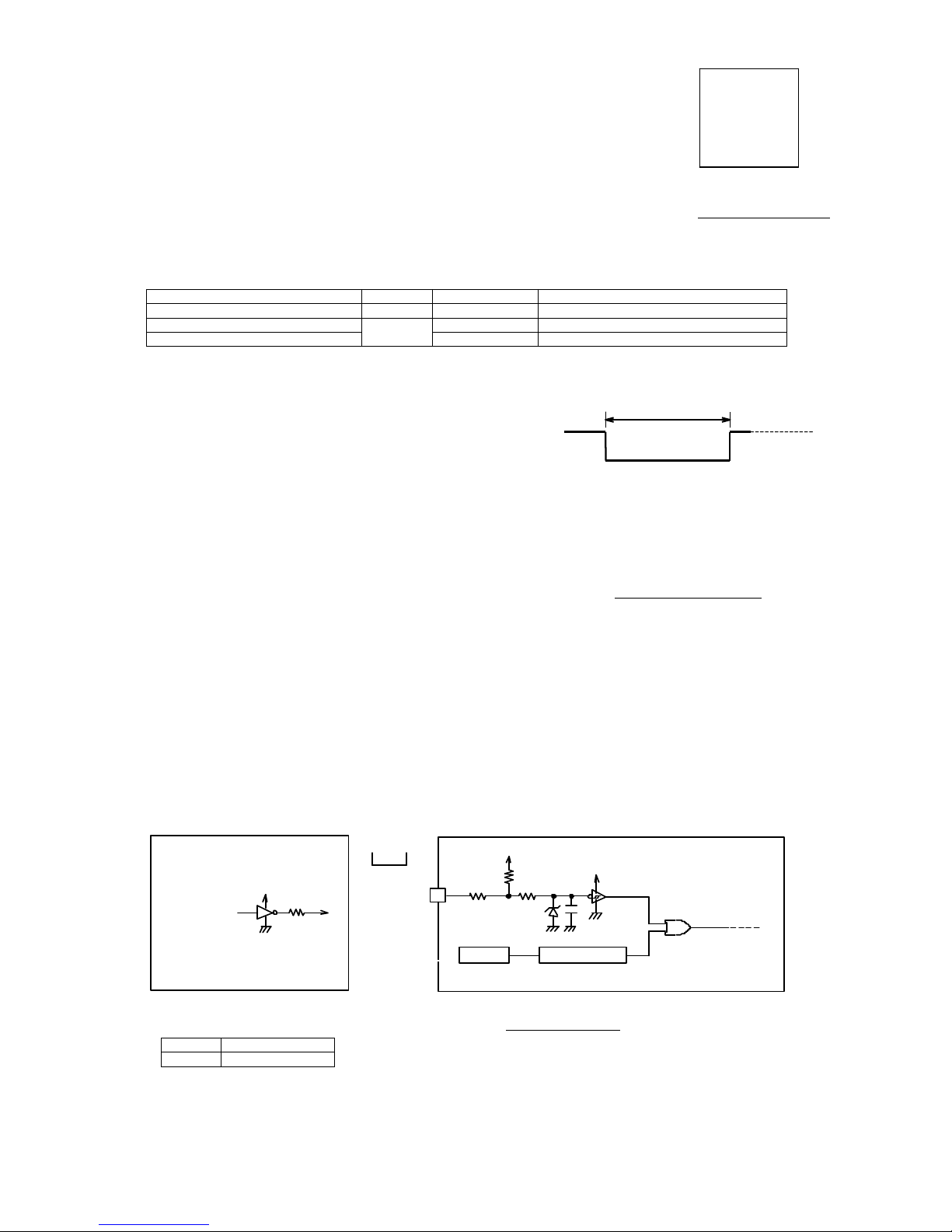
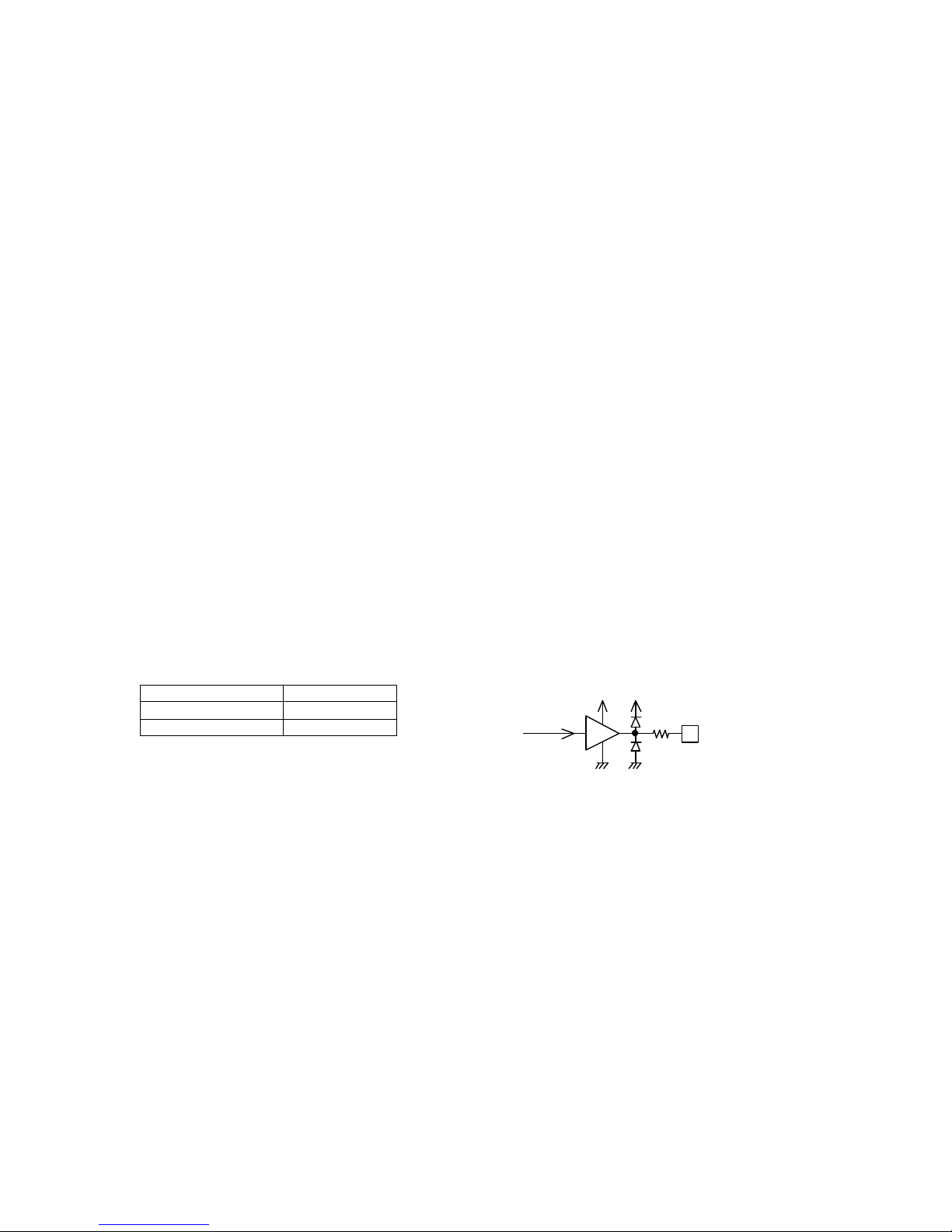
● Example of drive circuit for Vinit input circuit
* The Vinit signal should not include unnecessary noise components such as chattering.
[Input voltage range]
H level 2.5 to 5.5 V
L level -0.5 to 0.5 V
*
T
he voltage of the terminal end on camera side is required to be within the above voltage range with the camera being connected.
Red LED lights up in red in response
to trigger signal input (Vinit).
Camera
connector
75
Ω
6
Vini t1 IN
VCC
3.3V
4.7k
47p
3.3V
10k
100Ω
TC74LVX 14 or equivale nt
3.9 ZD
VCC is +
5V
or +3.3
V
74AC04 or
others
[Exam ple of user circuit]
GigE Serial I/F
P OW E R
E XP . M O DE
U
D
L E NS
Opera tio n indic ato rLE D
Fig. 4-2. LED indicator
Fig. 4-4. Vint circuit
K09821;8/37
- 8 -
S TR B s i gn al out pu t
( 11 )pi n o f Ca m er a c onn ec t or
1 0 0Ω
F r om
i n te r na l c ir c ui t
74VHCT04A
+5 V
(
or equivalent)
6.8 ZD
STRB
BUSY
OFF
Fig. 4-5. Strobe signal output circuit
(4-3) Strobe signal output circuit
The internal output circuit is shown in the right figure.
● Conventional cameras used the strobe signal (STRB) as
the exposure timing signal only. In this equipment, this can
be switched between OFF, STRB signal (continuous &
asynchronous) and Busy signal(asynchronous) by setting.
This setting can be changed on the configuration menu
(Operation Mode Setting Group 3) or by way of rewriting the
configuration register with serial communication command.
The default setting is OFF (no strobe signal).
This equipment is capable of outputting the strobe signal even in the continuous shutter mode as well as in the
asynchronous shutter mode when the setting is changed to output the strobe timing signal(STRB).
[Explanation] Usage of strobe signal in continuous shutter mode
In the continuous shutter mode, only the incoming light for the time matching the exposure time of the camera is valid.
Accordingly, when a lighting unit is used in the continuous lighting mode, the lighting during the time other than this exposure time
period would be wasted.
Since this equipment is capable of outputting strobe signal (STRB) even in the continuous shutter mode, this output is used as a trigger
signal to control a LED light or other lighting units that can be turned on and off at high frequencies, which helps eliminating the lighting
during the useless lighting time.
The following benefits are derived from this type of lighting control:
● The consumption of the power to a light can be saved by way of lighting only during the valid time for exposure.
● The occurrence of smear is reduced because no light enters any time other than the exposure time periods.
(Note) When the strobe signal is used in the continuous shutter mode to make ON/OFF control on a lighting source unit,
the following must be taken into consideration:
Wherever possible, use a strobe lighting unit or others that are equipped with a power source separated from that
of the camera (electrically isolated power source) and a trigger input terminal (photo coupler input, etc.). If a
lighting unit that shares a power source or a ground circuit with the camera is turned on or off by the strobe signal,
the image output from the camera may have noise due to the influence of the fluctuation of the power supply
voltage or change in the electric potential that occurs at the ON/OFF timing.
Even when the insulation aforementioned is applied, the electromagnetic induction may lead to the occurrence of
noise on the image signal if the electric current of the lighting unit to be control is large. In this case, a measure
must be introduced to reduce electromagnetic induction noise arising from the lighting unit.
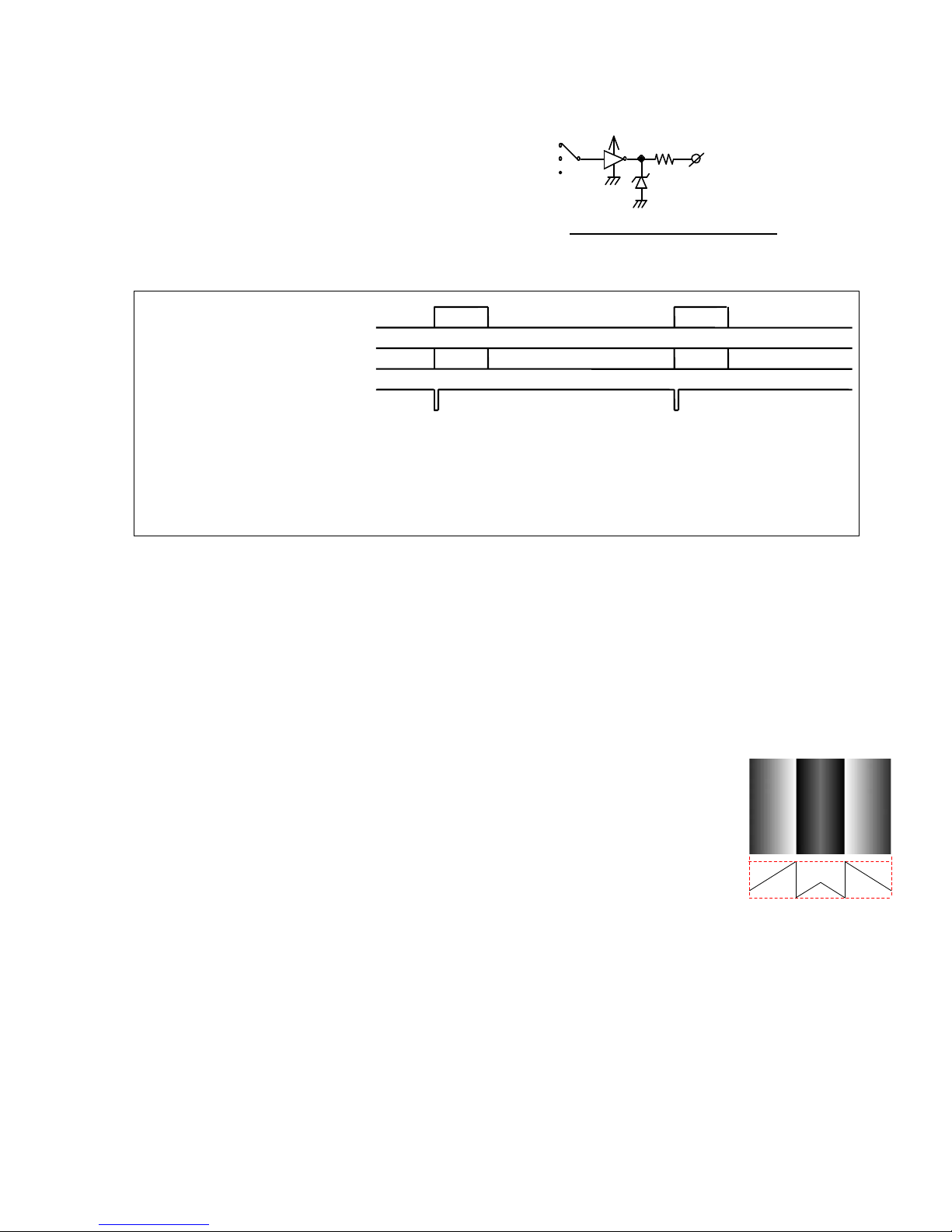
(4-4) Test pattern display function
When initially connecting this camera to an image capture board, the use of the test pattern display
function of the equipment makes it easier to confirm that the output timing of the camera and the
details of the signal connection match the particulars of the capture board.
When the test pattern function is set to be ON, the image sensor outputs the test pattern in place of
pictures as shown on the right.
As for this pattern, a numerical value of 1 is simply added in an incremental manner for every
horizontal pixel, and a saw-tooth profile is shown in the range from the numerical value of 0 to 1023.
(Note) In the data, a numerical value of 1 is incrementally added for every horizontal pixel in the
range of 0 to 1023 for the case of 10 bit output, and in the range of 0 to 255 for the case of 8
bit output.
(Note) The value does not start with 0 at the edge of the effective image area.
(Note) The output values of the test pattern are not affected by the values of the gain setting or offset setting of the
camera.
The default setting is OFF. This setting can be changed on the configuration menu (Operation Mode Setting Group 4) or
by way of rewriting the configuration register with serial communication command.
[Procedure for switching test pattern output ON/OFF]
(1) Start up in the Setting group 4.( Set the mode switch to the position “D”, keeping the power to the camera off. Then
turn on the power of the camera while turning and keeping the UP/DOWN switch lever to the either of upper or lower
position).
(2) Return the UP/DOWN switch lever to the neutral position when the response sound of “pip-pip” is heard
(3) Change the position of the mode switch to “2” after confirming that LED indicator flashes in orange.
(4) The test pattern display gets ON by stroking UP/DOWN switch upward and gets OFF by stroking that downward.
(5)
Switch to OFF when Test pattern is not necessary anymore. Since the setting of the test pattern output is
automatically saved, the test pattern will be output with last setting when the power is reapplied from next time.
Shutter exposure time
Continuous lighting
STRB signal
Exposure
Exposure
Valid
Useless lighting time
Valid
Useless lighting time
0
1023
Te st pa tt e rn an d h or i zo nt al pr o fi le

K09821;9/37
- 9 -
(4-5) Monitoring function for internal temperature of camera
This camera is equipped with an internal temperature sensor to monitor the temperature inside the body. This function
makes it possible to use the camera in a safer way even in a harsh environment in terms of temperature, for example use
in the open air. With the use of serial communication commands, this function also works to control the forced air-cooling
fan of the camera and peripheral devices and others.
● How to monitor internal temperature of camera
The following two methods are available for monitoring the internal temperature of the camera:
● Turn on the MENU display and confirm on the OSD over the image. (Temperature to be displayed in Celsius)
● Confirm with temperature data to be returned in response to the serial communication command (”RTMP”
command). (Numerical conversion required separately)
(Note) Carefully note that the temperature data obtained by this monitoring function is not for the ambient temperature but
the internal temperature of the camera. As a general rule, the internal temperature of the camera is higher than the
ambient temperature because of the heat generation associated with the consumed electric power inside the
camera.
Even when the temperature monitored by this function exceeds the value of the “Operation ambient temperature”
shown in the specifications of the camera, no operational trouble will be caused as long as the ambient
temperature is equal to the one of the specifications or lower, and sufficient countermeasures against temperature
are taken.
● Detection capability for temperature data
Minimum unit for temperature data : 0.5°
Data refreshing cycle : 0.4 sec.
Temperature detection accuracy: ±2°C (-40°C to +85° C), +3 to -2°C (55°C to 125°C)
Effective data range : -55°C to 125°C (as long as t he operation ambient temperature of the camera is
within the range defined by the specifications.)
● Temperature data by serial communication
The temperature data to be returned in response to the “RTMP” command of serial communication is generated in the
following format:
[Data format]
The lower 10 bits out of the 16 bits of the returned data are valid.
XXXXXD9D8…D0 (invalid upper 6 bits/valid lower 10 bits as the data)
Db=B’D9D8…D0 in the binary system shows a signed integer value in two’s complement form.
However, the effective range of the temperature data is limited to the following due to the operational restriction of the
temperature sensor:
Effective range of temperature data: -110 (-55°C) to +250 (125°C)
(Note) The accuracy of the values of the temperature data is not guaranteed when the operation ambient temperature is
not within the range defined by the specifications.
[Conversion method from returned data to temperature in Celsius]
The temperature in Celsius is computed as Tc from the following formula where Dt is the signed integer number converted
from the above described 10 bit binary value of “Db=B’D9D8…D0”:
Internal temperature of camera: Tc=Dt×0.5°C
(Example 1) Where Td, the returned value of the temperature data, is “H’0032” in the hexadecimal system, it is
expressed in the binary system as follows:
Td=H’0032=B’0000.0000.0011.0010
∴ Db=B’00.0011.0010 =+50 (Only upper 10 digits of Td are valid.)
Then, Tc is calculated from the following formula: Tc=+50×0.5°C=+25°C
(Example 2) Where Td, the returned value of the temperature data, is “H’03FA” in the hexadecimal system, it is
expressed in the binary system as follows:
Td=H’03F1=B’0000.0011.1111.1010
∴ Db=B’11.1111.1010 (Only upper 10 digits of Td are valid.) → Dt=-6
Then, Tc is calculated from the following formula: Tc=Dt×0.5°C=-6×0.5°C=-3°C
K09821;10/37
- 10 -
(4-6)
Operation confirmation buzzer
This equipment is designed to sound the confirmation buzzer of “pip” when a stroke is applied to the UP/DOWN switch on
the rear panel, or at the time of other manipulation including the start-up after power application.
The factory default setting is ON. This setting can be changed to cancel the buzzer.
[Procedure for switching buzzer between ON/OFF]
(1) Start up in the Setting group 3.( Set the mode switch to the position “C”, keeping the power to the camera off. Then
turn on the power of the camera while turning and keeping the UP/DOWN switch lever to the either of upper or lower
position).
(2) Return the UP/DOWN switch lever to the neutral position when the response sound of “pip-pip” is heard
(3) Change the position of the mode switch to “2” after confirming that LED indicator flashes in orange.
(4) The buzzer sound gets ON by stroking UP/DOWN switch upward and gets OFF by stroking that downward.
(5)
Turn off the power following the completion of setting . Since the setting is automatically saved, the camera starts up
with the last setting when the power is reapplied from next time.
(4-7) Camera ID saving function
The ID code and other information set by the user for each camera can be stored in the camera and be read out when
needed. The saved identification data for each camera including installation location in the case of using more than one
camera (e.g., “CAMERA-RIGHT” and “CAMERA-LEFT”) allows the user to easily control and identify the camera (s).
The setting is executed through the serial communication. The settable maximum number of characters are 15, and
alphabets (both upper and lower cases), numbers and some special symbols such as”+” and “-” excluding the control
codes can be used.
(→ Refer to the section of “Serial Communication Control” for the details.)
(4-7) Automatic Correction Function
The CCD in this equipment has 2ch output ports (right and left), and the image signal can be read out in high speed from
both ports.(Dual mode) At that time, the right and left halves of image data are synthesized to make a full area picture
image bringing together at a center boundary of the screen. Then the right and left output may differ in level, as the both
output characteristics are not exactly the same. This equipment has the automatic correction function to reduce and
obscure the level difference at the boundary. The factory default of this function is OFF. It can also correct the level
difference manually deactivating the automatic correction function. Depending status of camera usage, difference in level
or border line may appear on the center boundary. However, it does not arise from camera failure.
(4-8) Auto Iris Signal (IRIS) output circuit
This signal is effective as Auto Iris control signal only in no shutter mode or continuous shutter mode.
Signal output level 0 to 0.7 V (DC)
Output impedance
75 Ω
Asynchronous signal No signal
+ 3 .3V
I R I S s i gn a l
3
Fr o m
in t e rn a l c i rc u i t
7 5Ω
A M P
+3. 3 V

K09821;11/37
- 11 -
5. Various Settings
(5-1) Operation mode
● CCD output mode ······· DUAL / SINGLE
● Electronic shutter operation mode
Shutter system
No shutter / continuous/asynchronous
Type of shutter speed
High speed / low speed/pulse width control
(See the right schematic diagram)
● Scanning system ········· Normal scan / partial scan
→ Refer to section 6 for specific setting procedure.
(!) This camera does not support the functions of
“low speed/asynchronous shutter”.
Table 5-1. CCD output modes
CCD
output
mode
DUAL output
Image signal is output from light-and-left output ports simultaneously. High speed
readout is realized by using two output ports.( High frame rate)
SINGLE output
Image signal is output from single output port. Stable image can be obtained by using
single output port sacrificing the frame rate to some extent.
Table 5-2. Electronic shutter operation modes
Shutter
system
No shutter
Electronic shutter is not used.
Exposure time of image sensor is equivalent to one frame duration.
Exposure is continuously performed for each frame.
Continuous shutter
Repeats exposure regardless of external trigger input (Vinit).
Repetition pitch is per frame.
Asynchronous
shutter
Electronic shutter is released each time the external trigger is input (Vinit).
The shortest repetition pitch is [exposure time + 1 frame duration].
Table 5-3. Type of shutter speed
Type
of
shutter
speed
Normal shutter
(High speed shutter)
Shutter ,of which the exposure time is less than one frame, is used.
The exposure time can be set as a preset shutter speed at 9 different
levels both for
the continuous shutter/asynchronous shutter operations.
Low speed shutter
The shutter, of which the exposure time is two frames or over, is used.
(Only for continuous shutter mode) The exposure time can be set as a preset shutter
speed at 9 different levels.
(Note) This camera allows this setting only for the continuous shutter mode.
Pulse width control
Only in the case of asynchronous shutter setting, the shutter, of which
the exposure
time corresponds to the pulse width (during L level) of the
external trigger input
(Vinit), is released.
Exposure time can be set as nH (n = 1 or larger integer number)
in H (horizontal
synchronous time) unit.
Table 5-4. Other operation mode
Scanning
system
Normal scan The readout for each frame is conducted by the all pixel readout scanning.
Double speed scan
T
he readout for each frame is conducted by the double speed scanning (2 lines
binning). Image data is vertically compressed in half.
(!) Sometimes light and dark may be reversed because of vertical binning of image signal when the image signal
becomes excessively saturated. In that case, lower the image signal level (e.g. by
stopping down the aperture of the
lens a notch)
(!) If the double speed scanning is used in the color camera (FS11000GE), it becomes difficult to obtain the normal
color image as the color information is also added up.
[Terminology] Preset shutter ·········· This refers to the shutter speed setting other than those specified by the pulse width
control. More specifically, the shutter speed is set by the shutter switch positions
from “1” to “9” for the continuous shutter operation, or the shutter switch positions
from “1” to “9” (PWC (Pulse width control mode)=DISABLED) or from “1” to “8”
(PWC (Pulse width control mode)=ENABLE) for the asynchronous shutter operation.
The shutter speed is defined in the Table 6-1.
[Terminology] Pulse width control ····· This is the way of setting and controlling of the shutter speed by the width of the Vinit
signal that is externally input in the asynchronous shutter mode. With this camera,
this is selected by setting PWC to “ENABLED” and the shutter switch position to “9”
in the asynchronous shutter mode.
[Terminology] High speed shutter ····· This means the shutter of which shutter speed is shorter than 1 frame duration (=1
vertical synchronous time). The shutter speed is set as a preset fixed length of the 9
different levels that are determined by the position of the shutter switch (continuous
shutter and asynchronous shutter).
[Terminology] Low speed shutter ······ This means the shutter of which shutter speed is longer than 1 frame duration. The
shutter speed is set as a preset fixed length of the 9 different levels that are
determined by the position of the shutter switch (continuous shutter).
Electronic shutter
operation mode
No shutter
operation
Electronic shutter
operation
Shutter switch = 0
Shutter switch = 1 to 9
Asynchronous shutter
L
ow speed
shutter
Preset shutter
High speed
shutter
Preset shutter
High speed shutter
Pulse width control
High speed
shutter
Preset shutter
Fig. 5-1. Electric shutter mode
K09821;12/37
- 12 -
(5-2) Setting of shutter speed
The shutter speed is determined mainly by the shutter switch position from “0” to “9”.
When a shutter speed is specified using a communication command, the communication command is prioritized.
The shutter speed to be displayed is the one that is corresponding to the currently selected shutter switch position. When
“7” is selected for the mode switch, the current shutter speed can be changed.
(Note) The change of the shutter speed is enabled only when the shutter switch is set to any positions other than “0”.
As long as the shutter switch is positioned at “0”, the shutter speed cannot be changed even if “7” is selected for the
mode switch and the UP/DOWN switch is manipulated. (The shutter is always OFF where the shutter switch = “0”)
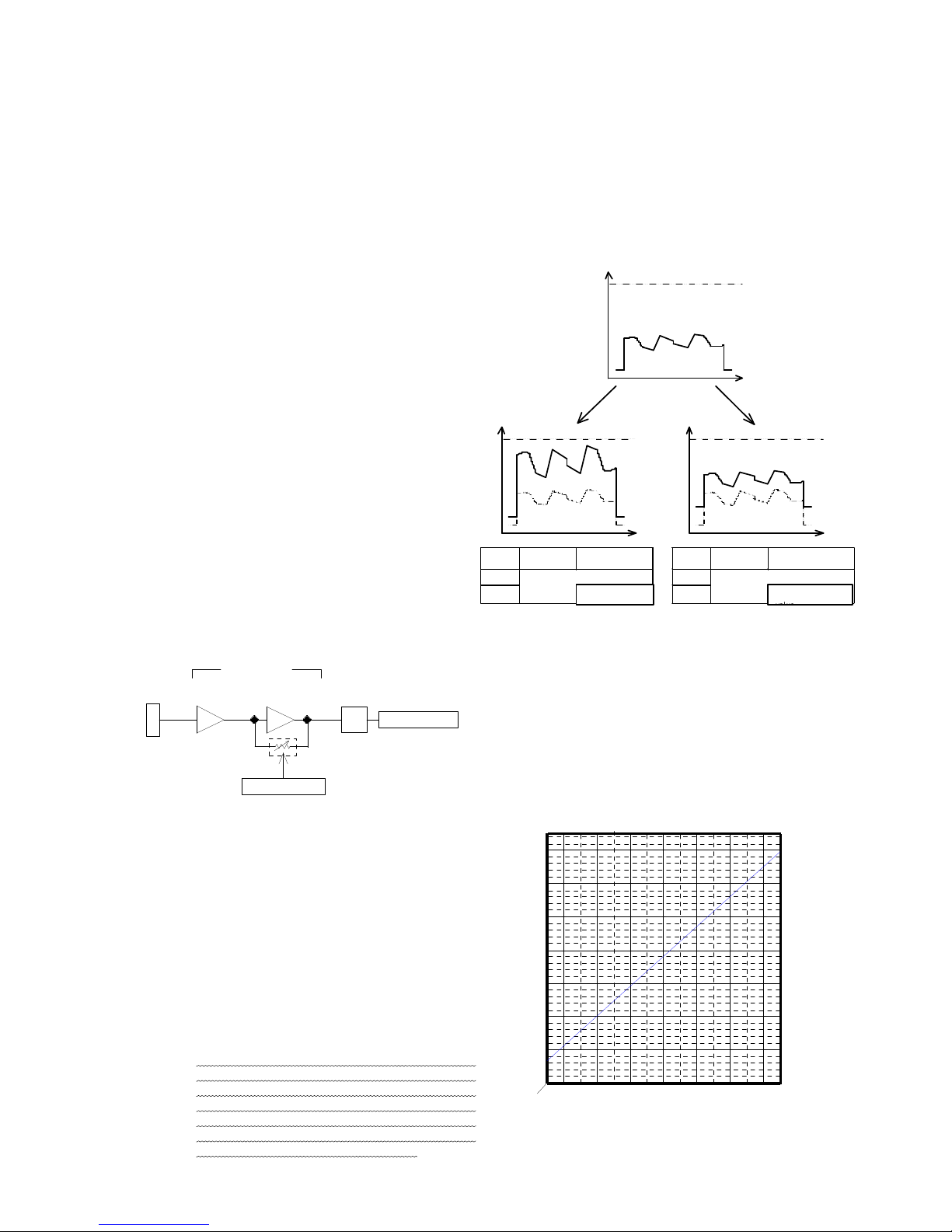
(5-3) Level setting
The level setting is mostly divided into the following
two groups:
● Gain setting
This is to set the gain (amplification ratio) of the
preamplifier between the CCD imaging device
inside the camera → A/D converter.
● Offset setting
This is to set the offset of the preamplifier between
the CCD imaging device inside the camera → A/D
converter.
→ Refer to the next section (Section 6) for the
specific setting method.
(Note) As for the offset setting, it is recommended to
use the factory default setting except for a
special case.
(Note) Follow the procedure (gain setting → offset
setting) if fine tuning of the offset value is
required.
(5-4) Gain setting of preamplifier
● Gain variable amplifier and integrated gain
The image signal output from CCD is amplified inside the
camera through the fixed gain amplifier on the anterior
stage and then through the following variable gain amplifier
before being input into the A/D converter.
The left block chart shows this flow.
(Note) The gain value (dB) described here is the one based on
the CCD output (0 dB) as the baseline.
● Correlation between MGC gain setting value and MGC gain
This equipment is controlled by giving the MGC setting
value. The correlation between this setting value and
the MGC gain (integrated gain including the gain of the
variable gain amplifier and that of the fixed gain
amplifier) is shown in the right graph.
(Note) When the CCD element receives excessive light
with a low gain value of the amplifier due to the
restriction of the dynamic range of the CCD light
receiving element, the signals of the nonlinear
area of the CCD element and the preamplifier
are output at the high brightness area.
In this state, unnatural image (Note below) may
appear in the neighborhood of the saturating
signal area of the image due to the
characteristic of the nonlinear area. This
phenomenon, which is associated with the
saturation characteristic of the CCD element, is
not a failure arising from the camera.
Signal level
Video waveform
(Before setting adjustment)
Increase in GAIN
Increase in OFFSET
Signal level
Signal level
Output
system
Left side of
screen
Right side of
screen
Output
system
Left side of
screen
Right side of
screen
SINGLE
GAIN setting value
SINGLE
OFFSET settin
g value
DUAL
DUAL
OFFSET setting value
+ OFFSET B setting
GAIN setting value
+ GAIN B setting
C C D
Preamplifier
A / D
G AIN
Variable gainamplifier
0dB(Fixed
)
Integrated gain
MGC setting
Fixed gainamplifier
MGC GAIN CODE
M GC GA IN (dB)
10
20
30
40
20 40 60 80 A0 C0 E0
(hex)
32 64 96 128 160 192 224(dec)
Fig. 5-2 Conceptual diagram of gain and offset levels
Fig. 5-3 Gain setting
Fig. 5-4 Gain characteristics
 Loading...