

Gigawave US RFXCMT2058 Users manual
The information contained in this manual remains the property of RF Central and may not be
used, disclosed or reproduced in any other form whatsoever without the prior written
permission of RF Central.
RF Central reserves the right to alter the equipment and specification appertaining to the
equipment described in this manual without notification.
RFX-CMT Clip -On
OPERATORS MANUAL
Applicable to model
UNGA-CCAM-7024
(Software)
UNSW-CCAM-7024-01
D-Cam Clip-On Operators Manual Issue 1 Page 1 of 27
UNUM-CCAM-7024-01

CONTENTS
1 General safety information .......................................................................................................3
1.1 Health & Safety..................................................................................................................4
1.2 Maximum RF Power Density Limits ...............................................................................4
1.3 RF Safety Comments .......................................................................................................5
2 Introduction.................................................................................................................................7
3 Specifications.............................................................................................................................8
4 Connector pin outs........................................................................................................................9
3.1 ASI/SDI / CVBS Video BNC............................................................................................9
3.2 Video Connector................................................................................................................9
Audio Connector..........................................................................................................................10
3.3 Power Connector.............................................................................................................10
3.4 Remote Connector..........................................................................................................11
4 Module Descriptions ...............................................................................................................12
4.1 Block diagram..................................................................................................................12
4.2 Audio / Video Encoder....................................................................................................13
4.3 COFDM Modulator..........................................................................................................14
4.4 Power Amplifier................................................................................................................14
4.5 Front Panel PCB..............................................................................................................15
5 System operation....................................................................................................................16
5.1 Camera Interfaces ...........................................................................................................16
5.2 Powering up the Clip-On with the PA disabled...........................................................16
5.3 Status Monitoring (front panel LED).............................................................................16
5.4 Operator Controls / Menus ............................................................................................17
5.4.1 Initialization screen ..................................................................................................17
5.4.2 Current operational state screens ........................................................................17
5.5 System Configuration – Operations Menu (MPEG mode)........................................18
5.5.1 Ch / Frequency Menu.............................................................................................18
5.5.2 Select ASI Menu......................................................................................................18
5.5.3 Select MPEG Menu................................................................................................18
5.6 System Configuration – Operations Menu (ASI mode).............................................20
5.6.1 Ch / Frequency Menu.............................................................................................20
5.6.2 Select MPEG Menu................................................................................................20
5.6.3 Select ASI Menu......................................................................................................20
5.7 System Configuration – Engineering Menu................................................................20
5.7.1 Prog Channels .........................................................................................................20
5.7.2 Cable equalizer........................................................................................................21
5.7.3 LCD Contrast ...........................................................................................................21
5.7.4 Inventory ...................................................................................................................21
5.7.5 Audio input impedance (Z).....................................................................................21
5.7.6 Video Format (video line standard)......................................................................21
6 Preparing for operation ...........................................................................................................26
6.1 The CMT Clip-On transmitter ........................................................................................26
6.2 The Receiving Equipment..............................................................................................26
7 Appendix B: Table of DVB-T Bit Rates................................................................................27
D-Cam Clip-On Operators Manual Issue 1 Page 2 of 27
UNUM-CCAM-7024-01

1 General safety information
The information that follows, together with local site regulations, must be studied by
personnel concerned with the operation or maintenance of the equipment, to ensure
awareness of potential hazards.
WARNING- RF Power Hazard : High levels of RF power are present in the unit. Exposure to
RF or microwave power can cause burns and may be harmful to health.
Switch off supplies before removing covers or disconnecting any RF cables, and before
inspecting damaged cables or antennas.
Avoid standing in front of high gain antennas (such as a dish) and never look into the open
end of a waveguide or cable where RF power may be present.
Users are strongly recommended to return any equipment that requires RF servicing to RF
Central.
WARNING- GaAs / BeO Hazard : Certain components inside the equipment contain Gallium
Arsenide and Beryllium Oxide that are toxic substances. Whilst safe to handle under normal
circumstances, individual components must not be cut, broken apart, incinerated or
chemically processed. In the case of Beryllium Oxide, a white ceramic material, the principal
hazard is from the dust or fumes, which are carcinogenic if ingested, inhaled or entering
damaged skin.
Please consult your local authority before disposing of these components.
CAUTION- Tantalum Capacitors: When subjected to reverse or excess forward voltage,
ripple current or temperature these components may rupture and could potentially cause
personal injury.
CAUTION: This system contains MOS devices. Electro-Static Discharge (ESD) precautions
should be employed to prevent accidental damage.
D-Cam Clip-On Operators Manual Issue 1 Page 3 of 27
UNUM-CCAM-7024-01
1.1 Health & Safety
Exposure to Non-Ionizing (RF) Radiation/Safe Working Distances
The safe working distance from a transmitting antenna may be calculated from the
relationship:
PT. G R
D = √
In which: D = safe working distance (metres)
PT = transmitter or combiner power output (watts)
GR = antenna gain ratio = anti log (gain dBi ÷10)
w= power density (watts/square metre)
The RF power density value is determined by reference to safety guidelines for exposure of
the human body to non-ionizing radiation. It is important to note that such safety guidelines
are different throughout the world. Such safety guidelines are, from time-to-time, revised. For
this product, a maximum power density limit of 1w/m² is to be applied when calculating
minimum safe working distances.
Antenna Transmitter Power
Type Gain (dBi) Gain Ratio 2W 4W 10W 30W
Omni
1.2 Maximum RF Power Density Limits
The recommen ded RF Radiation Power Density limit is based upon the following published
documents:
a.) IEEE standard C95.1 1999 - IEEE Standard for Safety Levels with respect to Human
b.) Guidelines for Limiting Exposure to Time-varying Electric, Magnetic & Electromagnetic
Both documents define RF power density limits for "controlled" and "uncontrolled"
environments. An uncontrolled environment is defined as one in which the person subjected to
the RF radiation may be unaware of and has no control over received energy radiation.
Uncontrolled environment conditions can ar ise, even in the best regulated conditions; for this
reason the limits defined for the uncontrolled environment have been assumed for the
recommended limit.
Documents (a) and (b) also show the RF power density guidelines to be frequency dependent.
Different power density / frequency characteristics are presented in the two documents.
4π.w
4 2.5 1 1 1.5 2.5
Exposure to Radio Frequency Electromagnetic Fields, 3 kHz to 300 GHz.
Fields (up to 300 GHz) published in 1998 by the Secretariat of the International
Commission on Non-Ionising Radiation Protection (ICNIRP).
D-Cam Clip-On Operators Manual Issue 1 Page 4 of 27
UNUM-CCAM-7024-01

To avoid complexity and to avoid areas of uncertainty, we recommend the use of a single
power density limit across the frequency range 100 kHz to 300 GHz. The 1w/m² power density
limit we recommend satisfies the most stringent of the guidelines published to date.
Footnote: The IICNIRP document may be freely downloaded (PDF) from the internet at
www.icnirp.de/emfgdl; The IEEE standard is available www.ieee.org for a fee.
Issue Status
Issue Date Changes
1 27/02/2007 First Issue, this model variant
1.3 RF Safety Comments
Important Note: It must be remembered that any transmitting equipment radiating power at
frequencies of 100 kHz and higher, has the potential to produce thermal and athermal effects
upon the human body.
Mandatory Safety Instructions to Installers & Users
Use only the manufacturer or dealer-supplied transmitting antenna.
Antenna Minimum Safe Distance: 8 inches (20 cm)
Antenna Gain: 4.0 dBi referenced to a dipole. The Federal Communications Commission (FCC)
has adopted a safety standard for human exposure to RF (Radio Frequency) energy which is
below the OSHA (Occupational Safety and Health Act) limits.
Antenna Mounting: The antenna supplied by the manufacturer or radio dealer must not be
mounted at a location that, during radio transmission, any person or persons can come closer than
the above indicated minimum safe distance to the antenna provided. For this transmitter and
antenna, the safe distance is 8 inches (20 cm). To comply with current FCC RF Exposure limits,
the antenna must be installed at, or greater than: (1) The minimum safe distance as described
above and (2) In accordance with the requirements of the antenna manufacturer or supplier.
Base Station Installation: The antenna should be fixed-mounted on an outdoor permanent
structure. RF Exposure compliance must be addressed at the time of installation.
Antenna Substitution: Do not substitute any antenna for the one supplied or recommended by
the manufacturer or radio dealer. Such a substitution may expose a person or persons to excess
radio frequency radiation. You may contact your radio dealer or the manufacturer for further
instructions.
Warning: Maintain a separation distance from the antenna to a person(s) of at least 8 inches (20
cm). You, as the qualified end-user of this radio device must control the exposure conditions of
bystanders to ensure that the minimum separation distance (see above) is maintained between the
antenna and nearby persons in order to maintain RF Exposure compliance. The operation of this
transmitter must satisfy the requirements of Occupational/Controlled Exposure Environments, for
work-related use. Transmit only when person(s) are at least the minimum distance from the
properly installed, externally mounted antenna.
D-Cam Clip-On Operators Manual Issue 1 Page 5 of 27
UNUM-CCAM-7024-01

To be safe:
a) Operators should not stand or walk in front of any antenna, nor should they allow
anyone else to do so.
b) Operators should not operate any RF transmitter or power amplifier with any of its
covers removed, nor should they allow anyone else to do so.
D-Cam Clip-On Operators Manual Issue 1 Page 6 of 27
UNUM-CCAM-7024-01

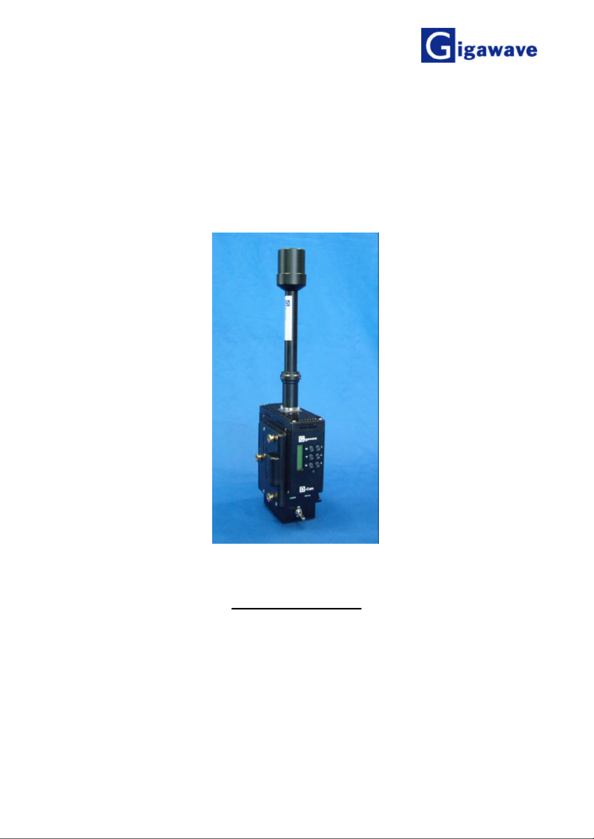
2 Introduction
This manual is specific for the RFX_CMT Clip-O n transmitter (model UNGA-CCAM-7024)
incorporating software suite UNSW-CCAM-7024-01. The unit incorporates features such as:
selectable standard delay or dedicated ultra low delay. Other notable features are memory
presets and manual setup of COFDM modulator configurations.
• The Standard Delay mode uses conventional MPEG-2 frame-based encoding with
choice of: MP@ML (4.2.0); MP@ML (4.2.2) plus special profiles optimized for low delay
(100 ms typical).
• The Ultra-low Delay version uses field-based encoding with special profiles optimized
for ultra low delay (40 ms throughout for all video bit rates).
The RFX-CMT Clip-On Wireless Camera system is designed for all applications (both indoor
and outdoor) in which a mobile camera is essential to the production of television programs.
The unique modular design of the RFX-CMT Clip-On transmitter ensures complete flexibility in
the choice of compression and modulation techniques to suit any required task, from the
highest video quality to the most rugged of RF signal paths.
The Clip-On transmitter contains an audio encoder, video encoder, COFDM modulator, power
supplies and an RF power amplifier. The transmitter accepts the attachment of an Omnidirectional antenna via an N- type connector.
External view of the D-Cam Clip-On
D-Cam Clip-On Operators Manual Issue 1 Page 7 of 27
UNUM-CCAM-7024-01

Frequency Band
3 Specifications
5.725 – 5.85 GHz band
Tuning Range
300 MHz standard bandwidth. Wider bandwidths available to special
order
Frequency Selection Up to 16 pre-set channels or tuning in ½ MHz steps via side mounted
panel control.
Transmit Power 100 mW
Transmit Antenna Omnidirectional 4 dBi gain (nom.)
Modulation COFDM DVB-T (2K Carriers)
Modulation Modes QPSK, 16QAM, 64QAM
1
FEC:
/2 2/3 3/4 5/6 7/
Guard interval:
8
1
/32 1/16 1/8 1/
4
Menu selectable via side mounted panel control
Data Rate 4.98 to 31.7 Mbit/s
Bandwidth 8 MHz (7 MHz & 6 MHz available)
Encoding Options MPEG-2 4.2.0/4.2.2 high quality (DVB standa rd)
Latency Standard delay - selectable to less than three frames minimum, Tx to Rx
Ultra low delay – one frame (40 ms), Tx to Rx (all video bit rates)
Video Input Digital: SDI 270Mbit/s
Analogue: YUV, Y/C Component
CVBS Composite Video (NTSC/PAL)
Audio Input 2 x Analog inputs (Mic/Line selectable)
Power Requirements Available with interface plates to mate with Anton/Bauer, IDX, PAG and
other batteries (to be specified at time of order) or 11 - 16VDC (18W) via
standard 4-pin XLR socket
Mechanical Interface Transmitter normally mounts between battery and battery interface plate
Size 160 x 130 x 54mm
Weight 0.95kg (including antenna)
Environmental Temperature: -20o to +50oC
Altitude: 4500m
Humidity: 95% humidity long term
D-Cam Clip-On Operators Manual Issue 1 Page 8 of 27
UNUM-CCAM-7024-01
Video input SDI ,
Component Video input,
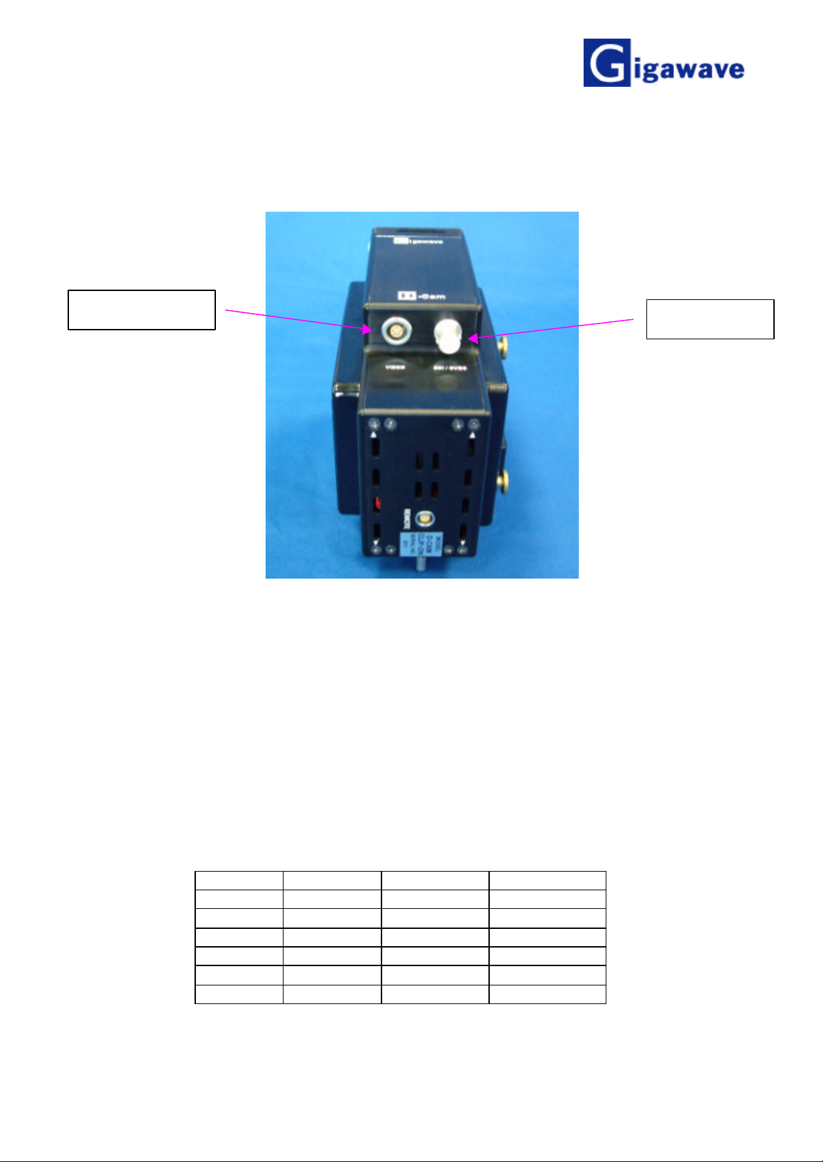
4 Connector pin outs
YUV, YC
CVBS or ASI
3.1 ASI/SDI / CVBS Video BNC
Either ASI or SDI or Composite video, blanking & sync (CVBS) input. Switched via the control
panel. See 5.5.3.4
75Ω BNC connector
3.2 Video Connector
Component YC / YUV / CVBS
6Pin Lemo Plug FGG.1B.306.CLAD62Z
Pin CVBS YC YUV
1 0V Y(0v) Y(0v)
2 CVBS Y Y
3 C(0v) U(0v)
4 C U
5 V(0v)
6 V
D-Cam Clip-On Operators Manual Issue 1 Page 9 of 27
UNUM-CCAM-7024-01
 Loading...