

Gigawave US CCAM 0102 Users manual
The information contained in this manual remains the property of Gigawave and may not
be used, disclosed or reproduced in any other form whatsoever without the prior written
permission of Gigawave.
D-Cam Clip -On
OPERATORS MANUAL
Copyright 2005 Gigawave Limited
D-Cam Clip -On Operators Manual Issue 1 Page 1 of 1
UNUM-CCAM-0104

CONTENTS
1 GENERAL SAFETY INFORMATION.....................................................................................3
1.1 Health & Safety......................................................................................................................4
1.2 Maximum RF Power Density Limits ...................................................................................5
1.3 Issue Status ............................................................................................................................5
2 INTRODUCTION.......................................................................................................................6
3 SYSTEM OPERATION................................ ............................................................................8
3.1 Camera Interfaces.................................................................................................................8
3.2 Operator Controls / Menus..................................................................................................8
3.2.1 Initialisation Menu..........................................................................................................8
3.2.2 Main Menu......................................................................................................................8
3.2.3 Ch / Frequency Menu.................................................................................................12
3.2.4 Encoder Menu................................ ..............................................................................12
3.2.5 Audio 1 Menu...............................................................................................................12
3.2.6 Audio 2 Menu...............................................................................................................12
3.2.7 Status Menu.................................................................................................................12
3.3 Status Monitoring................................................................................................................13
3.4 System Configuration – Engineering Menu....................................................................13
3.4.1 Prog Channels.............................................................................................................13
3.4.2 FW Inventory................................................................................................................13
3.4.3 Video Input ...................................................................................................................13
3.4.4 Video Format................................................................................................................14
3.4.5 Temperature.................................................................................................................14
4 PREPARING FOR OPERATION..........................................................................................18
4.1 The D-Cam Clip-On Camera Back...................................................................................18
4.2 The Receiving Equipment ..................................................................................................18
5 D-Cam Clip-On Transmitter...................................................................................................20
5.1 Connector Pin Outs.............................................................................................................20
5.1.1 SDI / CVBS Video BNC..............................................................................................20
5.1.2 Video Connector ..........................................................................................................20
5.1.3 Audio Connector ..........................................................................................................21
5.1.4 Power Connector.........................................................................................................21
5.1.5 Remote Connector ......................................................................................................21
5.2 Audio / Video Encoder........................................................................................................22
5.3 COFDM Modulator ..............................................................................................................23
5.4 Power Amplifier....................................................................................................................24
5.5 Front Panel...........................................................................................................................24
5.5.1 Default Parameter Set................................................................................................25
6 System Monitoring / Setup.....................................................................................................26
6.1 Main Menu............................................................................................................................26
Program Channels ................................ ......................................................................................27
6.2.1 List All Channels..........................................................................................................27
6.2.2 Program Channel........................................................................................................28
6.3 Dump Setup.........................................................................................................................29
6.4 Unit Name.............................................................................................................................30
D-Cam Clip -On Operators Manual Issue 1 Page 2 of 2
UNUM-CCAM-0104

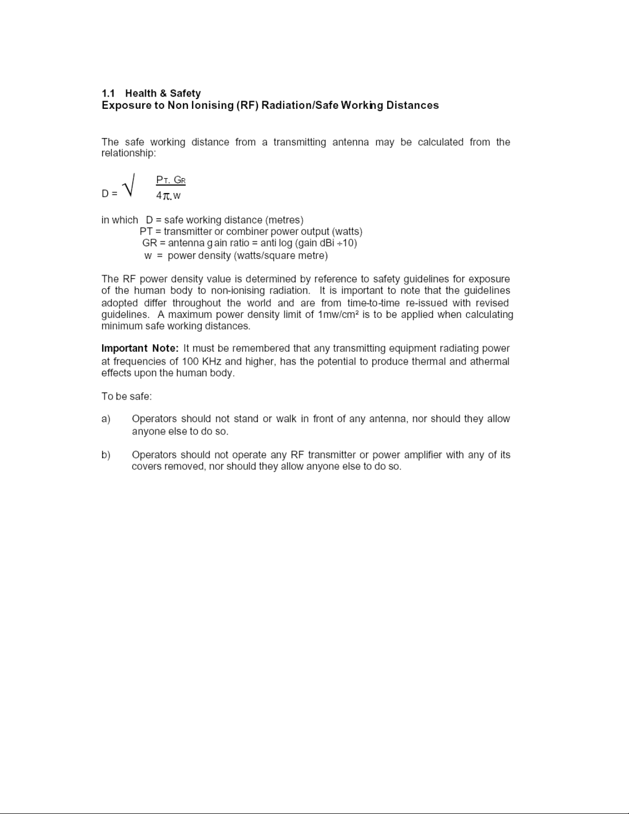
1 GENERAL SAFETY INFORMATION
The information that follows, together with local site regulations, must be studied by
personnel concerned with the operation or maintenance of the equipment, to ensure
awareness of potential hazards.
WARNING- RF Power Hazard : High levels of RF power are present in the unit. Exposure
to RF or microwave power can cause burns and may be harmful to health.
Switch off supplies before removing covers or disconnecting any RF cables, and before
inspecting damaged cables or antennas.
Avoid standing in front of high gain antennas (such as a dish) and never look into the open
end of a waveguide or cable where RF power may be present.
Users are strongly recommended to return any equipment that requires RF servicing to
Gigawave.
WARNING- GaAs / BeO Hazard : Certain components inside the equipment contain
Gallium Arsenide and Beryllium Oxide that are toxic substances. Whilst safe to handle
under normal circumstances, individual components must not be cut, broken apart,
incinerated or chemically processed. In the case of Beryllium Oxide, a white ceramic
material, the principal hazard is from the dust or fumes, which are carcinogenic if ingested,
inhaled or entering damaged skin.
Please consult your local authority before disposing of these components.
CAUTION- Tantalum Capac itors: When subjected to reverse or excess forward voltage,
ripple current or temperature these components may rupture and could potentially cause
personal injury.
CAUTION: This system contains MOS devices. Electro-Static Discharge (ESD)
precautions should be employed to prevent accidental damage.
This device complies with part 15 of the FCC Rules. Operation is subject to the following
two conditions: (1) This device may not cause harmful interference, and (2) this device
must accept any interference received, including interference that may cause undesired
operation.
FCC Part 15.21
Changes or modifications not expressly approved by the party responsible for compliance
could void the user's authority to operate the equipment.
NOTE: The manufacturer is not responsible for any radio or TV interference caused by
unauthorized modifications to this equipment. Such modifications could void the user's
authority to operate the equipment.
D-Cam Clip -On Operators Manual Issue 1 Page 3 of 3
UNUM-CCAM-0104
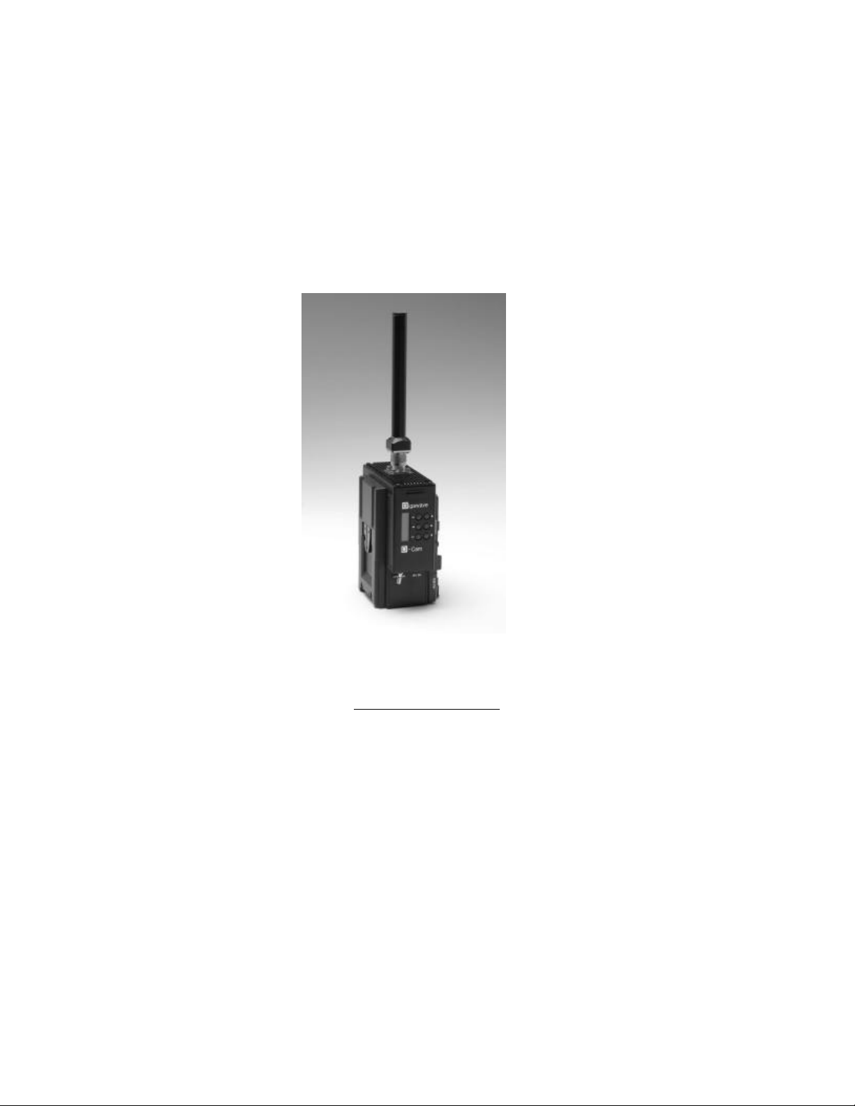
The unit is supplied with a 4dBi antenna that is fitted to the rear of the camera. The FCC RF
Exposure Evaluation has determined that a 20cm minimum safety distance must be maintained
between the antenna and all persons in the area.
Use of the unit with an external mast mounted antenna and / or power amplifier requires separate
RF Exposure Evaluation.
2 INTRODUCTION
This manual is to be used in conjunction with the D -Cam Clip-On unit (CCAM-0104) which
replaced the original 0101 & 0102 variants. The upgrade from 0101 to 0102 added the
extra feature of an SDI input. The upgrade from 0102 to 0104 added the extra features of
frequency selection to 0.5MHz increments. For details of the receiver please refer to the
relevant manual.
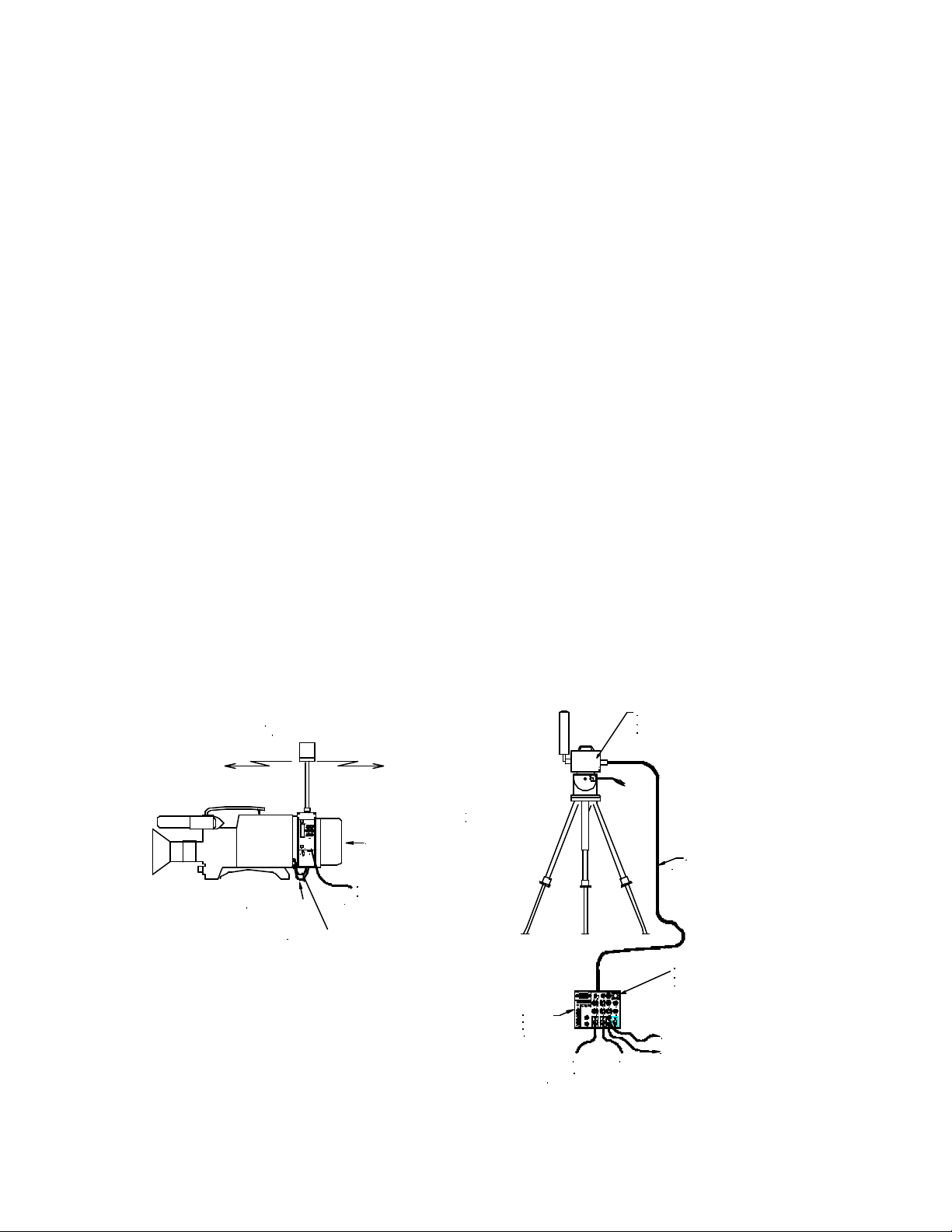
The Gigawave D-Cam Clip -On Wireless Camera system is designed for all applications,
both indoor and outdoor, in which a mobile camera is essential to the televised programme
production. The unique modular design of the Gigawave D-Cam Clip-On ensures
complete flexibility to change compression and modulation techniques to suit each
individual task required, from low delay or to the most rugged of RF signal paths.
The system is comprised of the Clip-On transmitter that contains an audio encoder, video
encoder, COFDM modulator, power supplies and an RF power amplifier. Attached directly
to this transmitter is an omni-directional antenna.
At the receive site the MVL-D two-box digital Receiver is used. No external decoders or
demodulators are required with this Receiver. The MVL -D is a two box rugged portable
system developed from proven technology from the analogue MVL series of Receivers
and Transmitters.
Digital low power
transmission
Video cable
G
igawave
EC
-Cam
OFF D12V DC
Audio cable
battery pack
Optional
DC input from
cameraman's battery belt
Tripod-mounting or
pole-mountable bracket
MVL-D
Receive
Control
unit
GIGAWAVE
GIGAWAVE
A2 A1VID
6 78
AGC
A3
45
910
-
-
-
-
-
-
INT
A4
3
11
0
0
0
0
2
12
+35+
+
+--+
+
+53+
CHANNEL1
MAN
INTERCOM MONITOR
dB
dB
INTERCOM
RECEIVE LEVEL dBm
0
0
110/230V AC
-80 -70-60 -20-30-40-50
+3-3
+3-3
2 AMP
CONTROL HEAD
AUDIO 1 AUDIO 3
REMOTE
LOCALALARMVIDEO ALARM
dB00dB
dB
POWER
0
ON
OFF
IN
+3-3
-3 +3
-3 +3
3.15 AMP
AUDIO 4AUDIO 2
VIDEO
BASEBAND
OUT
AUDIOS 3 & 4AUDIOS 1 & 2
10-30V DC
CLAMP
SAW
ON
OFF
NOR
70MHz IF OUT
MONITOR
4321
VIDEO
INV
A1 A2
Audio Outputs
- analogue or AES/EBU digital
MVL-D
Receive Head unit
and fanbeam antenna
'Triax' cable
(up to 600 Metres)
MVL Control unit with
integral digital decoder
and COFDM demodulator
SDI output 270 mbps
ANALOGUE output
D-Cam Clip -On Operators Manual Issue 1 Page 6 of 6
UNUM-CCAM-0104
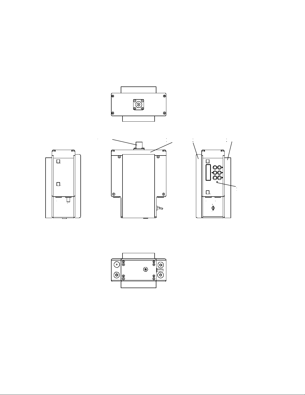
G
D
VIDEO
igawave
-Cam
RF OUTPUT
SDI
POWER
AMPLIFIER
CAMERA
INTERFACE
G
D
AUDIO
igawave
-Cam
OFF
BATTERY
CLIP
C E
STATUS
LED
12V DC
ON
External Views of the D-Cam Clip-On
D-Cam Clip -On Operators Manual Issue 1 Page 7 of 7
UNUM-CCAM-0104

3 SYSTEM OPERATION
3.1 Camera Interfaces
The D-Cam Clip-On can be supplied with one of three battery and camera interfaces:
• Sony ‘V’ Block / IDX
• Anton Bauer Gold Mount
• PAK
These provide a flexible and versatile mounting system suitable for a wide range of
cameras and battery options.
The D-Cam Clip-On is first mou nted onto the camera rear battery interface. If required, an
appropriate battery can then be docked onto the rear of the D-Cam Clip -On transmitter.
The video and audio cables must then be connected between the camera and the D-Cam
Clip-On, see 3.4.3 for details of the hardware configuration via the Control Panel.
If a battery is docked onto the rear of the D-Cam Clip-On, no external DC power lead is
required. This is only required to provide power to the D-Cam Clip -On and camera if a
battery belt / external power supply is used.
Care should be taken to prevent damage to an external power supply if a battery is
docked, as current can be taken FROM the Power Connector See 5.1.4.
3.2 Operator Controls / Menus
The D-Cam Clip-On is configured using an LCD display and six push buttons. These are
arranged as four navigation buttons ( ????), Enter and Clear.
The Enter button is used to store the modified parameter in non-volatile memory, this
parameter will then be used to configure the D-Cam Clip-On and will also become the
default value when next powered on.
The Cancel button can be used to exit a menu without storing the parameter in memory.
Various menu levels are provided to allow the operator to access the different hardware
and operating parameters:
3.2.1 Initialisation Menu
At switch on the status of the initialisation is displayed. If any errors are found with the
initialisation of the major functions; Video, Audio, Encoder and Modulator; an error
message will be displayed. During initialisation the Status LED will be off.
3.2.2 Main Menu
This is the display screen during normal operation of the D -Cam Clip-On and indicates the
Tx frequency, Memory option (or Manual frequency) and the current Encoder memory
settings. The ?? buttons are used to select the required sub -menus; Ch/Freq, Encoder,
Audio1, Audio2 and Status, the Enter button is then used to select. The ?? buttons are
used to display the current operational state.
During normal operation the Status LED will be green indicating ‘healthy’ state of the
D-Cam Clip-On.
D-Cam Clip -On Operators Manual Issue 1 Page 8 of 8
UNUM-CCAM-0104
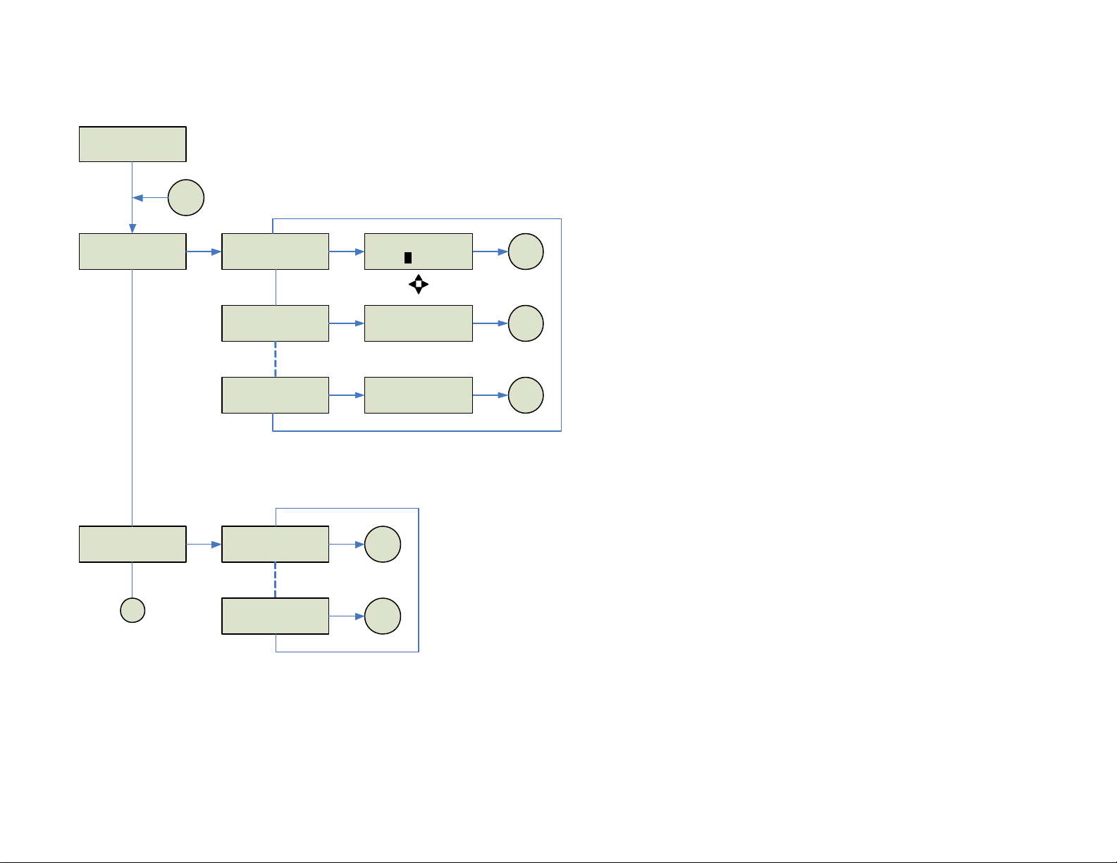
3.2.2
FREQ 2250.00 MHz
Mem0 – 64QAM 18M
3.2.3
MAIN ?
CH/FREQ
3.2.4
MAIN ?
ENCODER
?
?
?
?
TOP
E
CH/FREQ ?
FREQ 2250.00MHz
CH/FREQ ?
Ch1 1990 .00MHz
CH/FREQ ?
CH16 2492 .00MHz
E E/CCH/FREQ ?
FREQ 2250.00MHz2
?
?
E
Ch1 1990.00MHz
Mem0 – 64QAM 18M
?
?
E
Mem0 – 64QAM 18M
E/C
E/CCh16 2492.00MHz
Top
Top
Top
?
?
E to Enter & store program
C to Cancel
0
CHANNEL / FREQUENCY
E
ENCODER ?
Mem0 – 64QAM 18M
?
?
?
?
E/C
Top
?
?
3.2.5
ENCODER ?
Mem7 – QPSK 6M
E/C
Top
ENCODER
0
D-Cam Clip -On Operators Manual Issue 1 Page 9 of 9
UNUM-CCAM-0104
 Loading...