

MTV3- ASUM-7001-07 page 1 of 25
The information contained in this manual remains the property of Gigawave and may not be used,
disclosed or reproduced in any other form whatsoever without the prior written permission of
Gigawave.
Gigawave reserves the right to alter the equipment and specification appertaining to the equipment
described in this manual without notification.
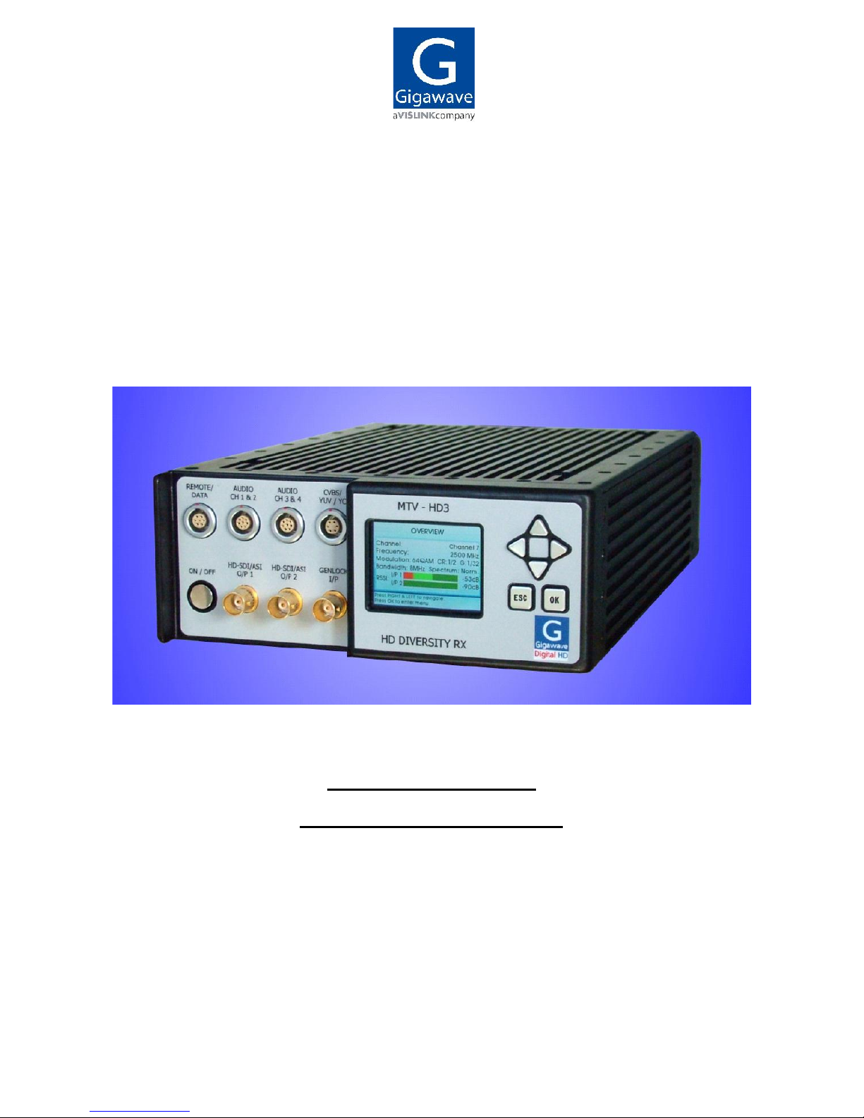
MTV-HD3 RECEIVER
H264/MPEG-4 and MPEG-2 version
OPERATOR’S MANUAL
Copyright 2011 Gigawave Limited

MTV3- ASUM-7001-07 page 2 of 25
CONTENTS
1 GENERAL INFORMATION ..................................................................................................... 4
1.1 General safety instructions ............................................................................................... 4
1.2 Disposal Instructions ......................................................................................................... 4
1.3 Environmental .................................................................................................................... 4
1.4 Health & Safety ................................................................................................................... 5
1.5 Maximum RF Power Density Limits .................................................................................. 6
1.6 Issue Status ........................................................................................................................ 6
2 GENERAL DESCRIPTION ...................................................................................................... 7
3 RECEIVER SPECIFICATIONS ................................................................................................ 8
4 PIN CONNECTIONS ............................................................................................................. 10
4.1 Front panel ........................................................................................................................ 10
4.1.1 SDI /ASI ..................................................................................................................... 10
4.1.2 Genlock input .............................................................................................................. 10
4.1.3 CVBS, YUV, Y/C ......................................................................................................... 10
4.1.4 Audio Connectors ........................................................................................................ 11
4.1.5 Remote control/User Data Connector .......................................................................... 12
4.2 Rear panel ......................................................................................................................... 12
4.2.1 Power Connector......................................................................................................... 12
4.2.2 10-32V DC .................................................................................................................. 12
4.2.3 RF Inputs (2 way diversity) .......................................................................................... 13
4.2.4 USB / Ethernet ............................................................................................................ 13
5 CONFIGURING THE RECEIVER .......................................................................................... 14
5.1 On / Off switch .................................................................................................................. 14
5.2 Operator Controls / Menus .............................................................................................. 14
5.3 Video monitoring on the front panel LCD screen .......................................................... 14
5.4 Current status and alarm screens ................................................................................... 14
5.4.1 Status overview screen ............................................................................................... 14
5.4.2 Status and alarm screens ............................................................................................ 15
5.4.2.1 Signal status......................................................................................................... 15

MTV3- ASUM-7001-07 page 3 of 25
5.4.2.2 Service information............................................................................................... 15
5.4.2.3 Decoder information ............................................................................................. 16
5.4.2.4 Unit status and alarms .......................................................................................... 16
5.5 Setup menus ..................................................................................................................... 16
5.5.1 Channel / Frequency Menu ......................................................................................... 16
5.5.1.1 Channel................................................................................................................ 16
5.5.1.2 Frequency ............................................................................................................ 17
5.5.1.3 Spectrum and bandwidth ...................................................................................... 17
5.5.2 Genlock ....................................................................................................................... 17
5.5.3 Inputs (decoder signal loss video output mode) ........................................................... 17
5.5.4 Outputs ....................................................................................................................... 17
5.5.4.1 Analogue outputs ................................................................................................. 17
5.5.4.1.1 Video................................................................................................................. 17
5.5.4.1.2 Analogue audio level adjustment ....................................................................... 17
5.5.4.1.3 Audio output impedance.................................................................................... 18
5.5.4.2 Digital outputs ...................................................................................................... 18
5.5.5 Services (MPEG decoder set up) ................................................................................ 18
5.5.6 Output ports ................................................................................................................ 18
5.5.6.1 User data ............................................................................................................. 18
5.5.6.2 USB port .............................................................................................................. 18
5.5.6.3 Ethernet port ........................................................................................................ 19
5.5.7 General settings .......................................................................................................... 19
5.5.7.1 Software versions ................................................................................................. 19
5.5.7.2 Display ................................................................................................................. 19
5.5.7.3 Unit name ............................................................................................................. 19
5.5.7.4 Advanced mode ................................................................................................... 19
5.5.7.5 USB upgrade........................................................................................................ 19
5.5.8 Decryption ................................................................................................................... 20
5.5.9 Receiver menu Tree .................................................................................................... 21
6 PREPARING FOR OPERATION ........................................................................................... 23
6.1 The MTV-HD3 receiver ..................................................................................................... 23
6.1.1 Antennas ..................................................................................................................... 23
6.1.2 Checks ........................................................................................................................ 23
6.2 Transmitter / Receiver tests............................................................................................. 23
7 TABLE OF COFDM BIT RATES ........................................................................................... 24
7.1 DVB-T bit rates ................................................................................................................. 24
7.2 ISDB-T bit rates ................................................................................................................ 25

MTV3- ASUM-7001-07 page 4 of 25
1 GENERAL INFORMATION
1.1 General safety instructions
The information that follows, together with local site regulations, must be studied by
personnel concerned with the operation or maintenance of the equipment, to ensure
awareness of potential hazards.
WARNING- RF Power Hazard: High levels of RF power are present in the unit. Exposure to RF or
microwave power can cause burns and may be harmful to health.
Switch off supplies before removing covers or disconnecting any RF cables, and before inspecting
damaged cables or antennas.
Avoid standing in front of high gain antennas (such as a dish) and never look into the open end of
a waveguide or cable where RF power may be present.
Users are strongly recommended to return any equipment that requires RF servicing to Gigawave.
WARNING- GaAs / BeO Hazard: Certain components inside the equipment contain Gallium
Arsenide and Beryllium Oxide that are toxic substances. Whilst safe to handle under normal
circumstances, individual components must not be cut, broken apart, incinerated or chemically
processed. In the case of Beryllium Oxide, a white ceramic material, the principal hazard is from
the dust or fumes which are carcinogenic if ingested, inhaled or entering damaged skin.
Please consult your local authority before disposing of these components.
CAUTION: Tantalum capacitors: When subjected to reverse or excess forward voltage, ripple
current or temperature these components may rupture and could potentially cause personal injury.
CAUTION: This system contains MOS devices. Electro-Static Discharge (ESD) precautions
should be employed to prevent accidental damage.
1.2 Disposal Instructions
All equipment, including batteries where applicable, should NOT be disposed of with household
waste as they are not bio-degradable in landfill sites. They should NOT be incinerated.
For safe disposal take to:
The local (council/authority) environmental waste site, (in Europe in accordance with the
European Environmental directive).
For details contact your local authority/recycling centre.
1.3 Environmental
It is recommended that the rain cover supplied with the equipment is used to protect the unit from
bad weather and pollution when used outdoors.
MTV3- ASUM-7001-07 page 5 of 25
1.4 Health & Safety
Exposure to Non Ionising (RF) Radiation/Safe Working Distances
The safe working distance from a transmitting antenna may be calculated from the
relationship:
D =
in which D = safe working distance (meters)
PT = transmitter or combiner power output (watts)
GR = antenna gain ratio = anti log (gain dBi 10)
w = maximum allowed power density (watts/square meter)
The RF power density value is determined by reference to safety guidelines for exposure of
the human body to non-ionising radiation. It is important to note that the guidelines adopted
differ throughout the world and are from time-to-time re-issued with revised guidelines. For
Gigawave use, a maximum power density limit (w) of 1w/m² is to be applied when calculating
minimum safe working distances.
Important Note: It must be remembered that any transmitting equipment radiating power at
frequencies of 100 KHz and higher, has the potential to produce thermal and athermal effects upon
the human body.
To be safe:
a) Operators should not stand or walk in front of any antenna, nor should they allow anyone
else to do so.
b) Operators should not operate any RF receiver or power amplifier with any of its covers
removed, nor should they allow anyone else to do so.
Worked examples
Antenna
Receiver Power
Type
Gain (dBi)
Gain Ratio
2W
4W
10W
30W
OMNI
4 2.5 1 1 1.5 2.5
HELIX
20 100 4 5.6 9 15.5
PARABOLIC
DISH
35 3,162 22.5 32 50 87
MINIMUM SAFE DISTANCE (METRES)
PT. GR
4.w

MTV3- ASUM-7001-07 page 6 of 25
1.5 Maximum RF Power Density Limits
The RF Radiation Power Density limit figure recommended by Gigawave is based upon guideline
levels published in:
a. IEEE standard C95.1 1999 - IEEE Standard for Safety Levels with respect to Human
Exposure to Radio Frequency Electromagnetic Fields, 3 KHz to 300 GHz.
b. Guidelines for Limiting Exposure to Time-varying Electric, Magnetic & Electromagnetic
Fields (up to 300 GHz) published in 1998 by the Secretariat of the International Commission on
Non-Ionising Radiation Protection (ICNIRP).
Both documents define guideline RF power density limits for "Controlled" and "Uncontrolled"
environments. An uncontrolled environment is defined as one in which the person subjected to the
RF radiation may be unaware of and has no control over the radiation energy received. The
uncontrolled environment conditions can arise, even in the best regulated operations and for this
reason the limits defined for the uncontrolled environment have been assumed for the Gigawave
recommended limit.
Documents a) and b) also show the RF power density guidelines to be frequency dependent.
Different power density / frequency characteristics are presented in the two documents. To avoid
complexity and to avoid areas of uncertainty, Gigawave recommends the use of a single power
density limit across the frequency range 100 KHz to 300 GHz. The 1w/m² power density limit we
recommend satisfies the most stringent of the guidelines published to date.
Footnote: The IICNIRP document may be freely downloaded from the internet at
www.icnirp.de/emfgdl (PDF file), the IEEE standard is available on loan from Essex County Library
on payment of a search fee.
1.6 Issue Status
Issue
Date
Changes
Updated by
1
5th March 2010 first issue
M. Robinson
2 24th March 2010 Revised connections paragraphs 4.1.3 and 4.2.4 M. Robinson
3 13th April 2010 Video monitoring on front panel LCD added M. Robinson
4 14th April 2011 Ethernet port pin connections, detail expanded M. Robinson
5 18th Dec 2011 MPEG-2, H264/MPEG-4 decoder introduced M. Robinson
6 25th Nov 2013 Basic Safety Requirement added S. Huynh

MTV3- ASUM-7001-07 page 7 of 25
2 GENERAL DESCRIPTION
The Gigawave MTV-HD3 mini receiver is designed for all applications, both indoor and outdoor,
where a very small light-weight unit is essential to the operation. The unit features two-way
diversity reception using Maximum Ratio Combining technology
The receiver is available with either DVB-T or ISDB-T demodulation (factory options)
The receiver is comprised of a single miniature unit that contains RF down-converter COFDM
demodulator MPEG decoder and video/audio output circuitry.
This version of the receiver features both MPEG-2 and H264/MPEG-4 decoding with automatic
selection.
In HD mode, in addition to the HD SDI output, the unit provides a down-converted to SD monitoring
quality output at the CVBS port.
Video picture monitoring is available on the full colour front panel LCD screen.
The unit provides 4 audios (2 stereo) with analogue, SDI embedded and AES/EBU digital outputs.
The receiver powers from 10 to 32VDC, and outputs HD SDI, SD SDI and analogue composite
video (CVBS), component YUV and YC, and ASI, Audio outputs are analogue, SDI embedded and
AES/EBU digital audio.
The receiver can be used with a variety of Gigawave antennas:-
PA series Low profile antennas are used for uplinking ground to air, or on-board linking
HX series antennas offer increased gain and directivity
FBA fan-beam antennas offer increased gain and 90 degree sector coverage.
Parabolic antennas offer the highest gain, and longest operational range
CO series Omni antennas are typically used for ground based mobile operations, or
helicopter air to ground
Full details are given in the Gigawave Antennas data sheet.
At the transmitting site a range of Gigawave digital transmitters may be used; for example the
complementary MTV-HD2 and D-Cam Clip-On, and MVL-D2 transmitters are available in both
H264 and MPEG-2 versions. Please consult the separate operator’s manuals for information
detailing transmitters.

MTV3- ASUM-7001-07 page 8 of 25
3 RECEIVER SPECIFICATIONS
RF Input
2x RF, N Type
Frequency Band
1.3 - 10 GHz band
Tuning Range
400MHz (modulation dependant, consult
factory)
Frequency Selection
Up to 16 pre-set channels or tuning in
1MHz steps via front panel control.
Programmable with 1MHz resolution to
customer
requirements within available bandwidth
(500kHz steps available to special order)
Receiver Noise Factor
4dB max.
Receiver Threshold
-92dBm to BER 10-5 (nom., QPSK)
Receive Antenna
Compatible with all Gigawave antennas
Demodulation
2 way Maximum Ratio Combining
Diversity reception
Demodulation Modes
DVB-T 2k
ISDB-T 2k (factory option)
QPSK, 16QAM, 64QAM
FEC:1/2, 2/3, 3/4, 5/6, 7/8
Guard interval: 1/32, 1/16. 1/8, 1/4
Data Rate
4.98 to 31.7 Mbit/s (automatic selection)
Bandwidth
DVB-T 6, 7, 8MHz
ISDB-T 6, 7MHz
Decoding
H264/MPEG-4 and MPEG-2 (automatic
selection).
Latency
Transmitter encoder dependant
Video Output
HD SDI SMPTE-292M (299M)
SD SDI SMPTE-259M (272M)
Analogue: composite (PAL/NTSC)
Analogue: component (YUV, YC)
HD down-converted to SD CVBS monitor
Video formats
1080i 1920 x 1080, 25 and 29.5Hz
720p 1280 x 720, 50 and 59Hz
480i (NTSC) 720 x 480
576i (PAL) 720 x 576
ASI Output
DVB ASI transport stream, 188 / 204
selectable
Genlock
Genlock input type, SD video –
composite black/burst
HD video – tri-level sync
Genlock timing offset feature

MTV3- ASUM-7001-07 page 9 of 25
Audio Outputs
Digital 2 x AES3 plus SDI embedded
Analogue 2 x stereo / 4 mono
User auxiliary data
Selectable 1200 to 230,400 baud
Power Supply
10 to 32VDC, 26 Watts typical
Monitoring
• Video picture monitoring on the full
colour LCD front panel display
• Comprehensive control and monitoring
menu via front panel control
• COFDM demodulator parameters
• RF Received signal level (dBm and bar
graph)
• C/N, MER, BER (dB and bar graph)
• Summary comprehensive internal lock
alarms
Remote control
Remote control and monitoring via
Ethernet port
USB software upgrade
Software upgrade via rear panel USB
port
Size
76mm high x 179 wide x 275 deep
Weight
2.9kg (6.4lbs)
Environmental
Safe use: -20° to +50°C
To spec: -10° to +45°C
Altitude: 4500m
Humidity: 95% long term
Mechanical Interface
Standard wedge plate compatible with all
Gigawave interfaces.
Specifications may alter at the discretion of Gigawave or to meet customer specific requirements.

MTV3- ASUM-7001-07 page 10 of 25
4 PIN CONNECTIONS
4.1 Front panel
4.1.1 SDI /ASI
Two outputs for either SDI or ASI. Each may be independently selected via front panel menu
system. See 5.5.4
75 BNC connector
4.1.2 Genlock input
Reference input for Genlock. Analogue CVBS or Tri level sync.
75 BNC connector
4.1.3 CVBS, YUV, Y/C
Analogue SD video, Composite PAL/NTSC (CVBS) or component YC / YUV
Connector Type: 6 pin LEMO connector EGG.1B.306.CLN
Pin
Video
CVBS
YC
YUV
1 Y(0v) Y(0v)
2 Y Y
3 0V U(0v)
4 CVBS U
5 C(0v) V(0v)
6 C V
Note: The wiring of this connector is different from the corresponding connector used on the
MTV-D2 TX and Clip-On Tx

MTV3- ASUM-7001-07 page 11 of 25
4.1.4 Audio Connectors
Line level output
AUDIO CH 1 & 2
Connector Type: 8 pin LEMO connector EGG.1B.308.CLN
1 channel AES3/EBU Stream, plus 2 x analogue (mono) audio outputs
Pin
1 Analogue Ground
2 A1 / Left +ve
3 A1 / Left -ve
4 A2 / Right +ve
5 A2 / Right -ve
6 Digital Ground
7 Digital +ve
8 Digital –ve
AUDIO CH 3 & 4
Connector Type: 8 pin LEMO connector EGG.1B.308.CLN
1 channel AES3/EBU Stream, plus 2 x analogue (mono) audio outputs
Pin
1 Analogue Ground
2 A3 / Left +ve
3 A3 / Left -ve
4 A4 / Right +ve
5 A4 / Right -ve
6 Digital Ground
7 Digital +ve
8 Digital –ve

MTV3- ASUM-7001-07 page 12 of 25
4.1.5 Remote control/User Data Connector
Connector Type: 7 pin LEMO connector EGG.1B.307.CLN
Dual purpose connector
User data output - RS232, see 5.5.6.1
MTV-HD3 RECEIVER remote control using RS232 or RS485, factory option (alternative to
remote control via Ethernet, see 4.2.4)
Pin note
1 0v
2 User Data Tx (out)
3 User Data Rx (in)
4 Tx+ (out) For RS232 use
only –ve
connections
5 Tx- (out)
6 Rx+ (in)
7 Rx- (in)
4.2 Rear panel
4.2.1 Power Connector
4.2.2 10-32V DC
Connector Type: 4 pin LEMO connector EGG.1B.304.CLN
Input range: 10V to 32V DC.
Pin
Function
1 0V
2 0V
3 +DC in
4 +DC in

MTV3- ASUM-7001-07 page 13 of 25
4.2.3 RF Inputs (2 way diversity)
Connector Type: 50Ω N (F) - quantity 2
4.2.4 USB / Ethernet
Connector Type: 8 pin LEMO connector EGG.1B.308.CLN
Dual purpose connector
Ethernet port for remote control and monitoring (web browser interface), see 5.5.6.3
USB port for unit software upgrade
Lemo pin
function
RJ45 wiring
USB wiring
1 TX+
Ethernet
Pin 1 Orange/white
2 TX- Pin 2 Orange
3 RX+ Pin 3 Green/white
4 RX- Pin 6 Green
5 0v Gnd
USB
Pin 4 Black
6 USB_p Pin 3 Green
7 USB_n Pin 2 White
8 +5v out Pin 1 Red

MTV3- ASUM-7001-07 page 14 of 25
5 CONFIGURING THE RECEIVER
5.1 On / Off switch
To turn the unit on, press the non-locking on/off button on the front panel and hold down for 1 to 2
seconds until the LCD screen illuminates and the unit begins to power up.
To turn the unit off, press the non-locking on/off button on the front panel and hold down for 2 to 5
seconds until the unit powers down.
5.2 Operator Controls / Menus
The MTV-HD3 receiver is configured using an LCD display and six push buttons. These are
arranged as four navigation buttons (▲▼◄►), OK and ESC (escape).
The OK button is used to store a modified parameter in non-volatile memory, this parameter will
then be used to configure the MTV-HD3 receiver and will also become the default value when next
powered on. The ESC button can be used to exit a menu without storing the parameter in memory.
5.3 Video monitoring on the front panel LCD screen
Received video picture monitoring is available on the full colour front panel LCD screen. To access
the function navigate to the Overview screen by repeatedly pressing the ESC button, the press the
left key, ◄. To navigate away from the video monitoring function press the ► key.
5.4 Current status and alarm screens
These screens show the current status of the unit, and whether any alarms are present.
To navigate between the status and alarm screens, press the ESC button several times to reach
the Status screen and use the ► button.
5.4.1 Status overview screen
This is the display screen during normal operation of the MTV-HD3 receiver and indicates the
Channel number, and Rx frequency. Provided the receiver is receiving a signal from the
transmitter, the display will show the modulation, the FEC code rate, the guard interval and the RF
bandwidth.

MTV3- ASUM-7001-07 page 15 of 25
When the receiver is locked to the transmitter and there are no alarms the button at the top left will
show green.
5.4.2 Status and alarm screens
These screens are accessed from the Overview screen by repeatedly pressing the ► button.
5.4.2.1 Signal status
The following functions are displayed:-
Carrier to noise (C/N) for the two RF inputs
MER (modulation error ratio)
Received Signal Strength Indicator (RSSI)
Bit error rate (BER)
Packet error count (PEC)
Note: The PEC shows cumulative errors, the readout may be set to zero by pressing the ▲key.
5.4.2.2 Service information
The following functions are displayed:-
Service name
Service ID
Encryption status
Transport stream PIDs

MTV3- ASUM-7001-07 page 16 of 25
5.4.2.3 Decoder information
The following functions are displayed:-
ASI status
Network name
Transport stream rate
Compression type MPEG-2 or H264
Video format
Genlock status
5.4.2.4 Unit status and alarms
Provides the alarm status of individual modules within the receiver
5.5 Setup menus
To access the setup menus from the Status screens press the OK button. Use the ▲▼ keys to
reach the required setup function and press the OK button.
Note: The functions provided in the setup menu depends on whether “Advanced mode” is set to
Enabled or Disabled in the General settings menu. The Advanced mode provides additional
features and is password protected. – see paragraph 5.5.7.4
5.5.1 Channel / Frequency Menu
5.5.1.1 Channel
This menu is used to select one of the sixteen pre-channels (CH1 – Ch16) or ‘manual’ frequency.
The manual frequency is set in 5.5.1.2

MTV3- ASUM-7001-07 page 17 of 25
5.5.1.2 Frequency
Displays the frequencies assigned for the 16 preset channels.
The ‘Man’ setting allows the transmit frequency to be set in 1MHz steps anywhere within the TX
operating band. The OK button allows the ◄► buttons to select the required digit, the ▲▼
buttons then select the required value. The OK button then stores the value.
Note: In Advanced Enabled mode the frequencies of the preset channels may be re-assigned. See
5.5.7.4
5.5.1.3 Spectrum and bandwidth
Allows the RF bandwidth of the COFDM signal to be set to 6, 7, or 8MHz.
Allows the RF spectrum to be set to either Normal or Inverted
Allows the Automatic Spectrum selection function to be enabled or disabled
Note: This function is only available in Advanced/Enabled mode. See 5.5.7.4
5.5.2 Genlock
The Genlock function of the receiver may enabled or disabled.
The Genlock reference may be set to analogue black and burst, or tri-level sync.
The video format may be set - e.g. 1080i
Additionally the timing reference of the Genlock function may be off-set from the reference
input according to the V (Line offset) and H (Pixel offset) +/- delay functions.
5.5.3 Inputs (decoder signal loss video output mode)
On loss of decoder lock, this function allows the video output to be set to: Either - last image
Or - Blue screen
5.5.4 Outputs
5.5.4.1 Analogue outputs
5.5.4.1.1 Video.
The video output from the 6 pin Lemo connector on the receiver front panel may be set to:
Either - Composite video (CVBS) plus Component Y/C
Or - Component Y, U, V
5.5.4.1.2 Analogue audio level adjustment
The receiver has 4 analogue audio outputs, arranged as two stereo pairs. Level adjustment is
provided a +5/-20dB in 0.1dB steps, on the nominal 0dB independently for pair 1 and pair 2.

MTV3- ASUM-7001-07 page 18 of 25
5.5.4.1.3 Audio output impedance
The analogue audio output impedance may be set to either 600 Ohms or Low impedance
Note: This function is only available in Advanced/Enabled. See 5.5.7.4
5.5.4.2 Digital outputs
The two BNC digital outputs on the receiver front panel may independently be set to:
Either - SDI – (SD or HD depending on the received signal video format)
Or - ASI
5.5.5 Services (MPEG decoder set up)
The internal MPEG decoder in the receiver may be set to decode video services in the received
transport stream. Three modes are provided:-
a) PID Auto. – The decoder will automatically detect the first video program in the received
transport stream and decode it. The decoded video and audio will be presented at the
output connectors of the receiver. (recommended configuration)
b) Service based – Where several video Services are contained in the received transport
stream, the number of Services will be displayed, and the operator may select the required
Service to be decoded, based on the Service name.
c) PID Fixed – Where more than one video program is contained in the received transport
stream, the operator may manually enter the PIDs of the required program to be decoded.
Note, this method should be used by skilled operators only, the PIDs contained in the
transport stream coming from the transmitter must be known by the operator prior to
selecting this option.
5.5.6 Output ports
5.5.6.1 User data
In addition to video and audio the receiver may also carry “User data” coming from the transmitter.
As an example; this function may be used for telemetry from sensors on On-boards, or reverse
camera control data to a wireless camera OCP unit.
The user data Baud rate may be set in the range 1200 to 230,400 Baud
The output interface may be set to either RS232 or RS485/422
The parity may be set to none/odd/even
The PID for the User data may be assigned
5.5.6.2 USB port
The USB port on the rear panel may be used for software upgrade of the receiver, for pin
connections see 4.2.4

MTV3- ASUM-7001-07 page 19 of 25
5.5.6.3 Ethernet port
The Ethernet port on the rear panel may be used for remote control and monitoring of the receiver
via a web browser interface, for pin connections see 4.2.4. To access the function, type the IP
address, as mentioned below, into the browser address bar. The default password is Gigawave; if
required the password may be modified by the user.
Ethernet control may be enabled or disabled. If enabled the IP address may be allocated by
DHCP server, or manually
SSH (Secure Shell) network protocol may enabled/disabled. SSH uses “SSH - Protocol 2”
connection type with “Blow fish” cipher in 256 bit asymmetric key + XTC + “Salt” mode. This
option should be left disabled for company debug purposes only.
5.5.7 General settings
5.5.7.1 Software versions
This menu provides a readout of the issue versions of the software installed on the receiver. This
information may occasionally be used in communication with the factory for customer service
purposes.
5.5.7.2 Display
Allows the back ground for the LCD colour display to set according to operator preference.
5.5.7.3 Unit name
Provides a readout of the Unit Name. The name is fixed the factory.
5.5.7.4 Advanced mode
The Functions provided in the Setup Menus depend on whether “Advanced mode” is set to
Enabled or Disabled in the General settings menu. When Advanced mode is enabled additional
features appear as green text in some menus. The Advanced/enabled mode also allows the 16
preset channel frequency to be changed by the operator, in advanced/disabled mode this feature is
greyed out.
The Advanced mode is password protected. The factory default is 0000, the password may be
changed by user if required.
5.5.7.5 USB upgrade
This feature allows the software in the MTV-HD3 receiver to be upgraded via the USB port on the
rear panel of the unit. Instructions for the upgrade procedure are provided by the factory with the
new software.

MTV3- ASUM-7001-07 page 20 of 25
5.5.8 Decryption
As a factory option, the receiver may be enabled to receive encrypted video signals according to
the EU ETSI scrambling algorithm, BISS modes 1 and E.
Set up of the BISS de-scrambling keys is through this menu. The MTV-HD3 receiver may either be
configured to use a single key for all receiver channels, or allow different keys for each channel.
A detailed explanation of the principles of BISS encryption, plus the selection and operation of
encryption is given in the separate Gigawave manual, which is available from the factory on
request.
Note: This function is only available in Advanced/Enabled mode. See 5.5.7.4

MTV3- ASUM-7001-07 page 21 of 25
5.5.9 Receiver menu Tree
Note: Items shown in green are only available in Advanced mode.
Channel frequency
Channel
Frequency
Spectrum and Bandwidth
Bandwidth
Automatic spectrum
Genlock
Type
Required Signal
Line Offset
Pixel Offset
Inputs
Decoder signal loss
Blue screen
Last image
Outputs
Analogue
Video type
Audio level Pair 1
Audio level pair 2
Audio impedance
Digital
Output 1
Output 2
Services
Auto PID
Fixed Service
Fixed PIDs
PMT
PCR PID
Video PID
Audio 1 PID
Audio 2 PID

MTV3- ASUM-7001-07 page 22 of 25
Output ports
User data
PID
Interface type
Baud rate
Parity
Remote
Local Int type
Ethernet
Enable/disable
Allow SSH
General settings
Software version
Display
Theme
Unit name
Advanced mode
Enable / disable
Change PIN
USB upgrade
Decryption
Configure
Enable/disable
Per Ch. Setup
Unit setup or channel X setting
BISS level
BISS-1 key
BISS-E ESW
Injected ID
Buried ID

MTV3- ASUM-7001-07 page 23 of 25
6 PREPARING FOR OPERATION
EQUIPMENT PREPARATION
Before leaving the equipment base to undertake an operation it is recommended that the following
equipment checks be made.
6.1 The MTV-HD3 receiver
6.1.1 Antennas
The MTV-HD3 receiver can be used with a variety of Gigawave antennas; for information
please see the Gigawave Antennas data sheets.
6.1.2 Checks
The receiver may be powered from an external DC PSU, or by batteries. Check that any batteries
to be used are fully charged and that an emergency spare battery is available and fully charged.
Confirm the correct frequency is selected. 5.5.1
Confirm that the correct digital outputs are selected, SDI or ASI. 5.5.4.2
Confirm the correct Video format for Genlock is selected. 5.5.2
Confirm the correct Analogue Audio level is selected. 5.5.4.1.2
Confirm that the correct MPEG decoder setting for video Services is selected. 5.5.5
Check that the Video, audio, DC and RF cables are in good condition.
6.2 Transmitter / Receiver tests
Whenever practical, set up the system and trial it before leaving for site to ensure that
all components of the system are working. Checking at base, where adjustments and
corrective actions can be made, will pay off when setting up at site.

MTV3- ASUM-7001-07 page 24 of 25
7 Table of COFDM bit rates
7.1 DVB-T bit rates
DVB-T Bit Rates - 6 MHz
CODE
RATE
Guard interval = 1/32 Guard interval = 1/8 Guard interval = 1/4
QPSK 16QAM 64QAM QPSK 16QAM 64QAM QPSK 16QAM 64QAM
1/2 4.52 9.08 13.57 4.14 8.29 12.44 3.73 7.46 11.19
2/3 6.03 12.06 18.08 5.52 11.05 16.58 4.97 9.95 14.92
3/4 6.78 13.57 20.35 6.22 12.44 18.66 5.59 11.19 16.79
5/6 7.54 15.08 22.62 6.91 13.82 20.73 6.22 12.44 18.66
7/8 7.91 15.83 23.75 7.25 14.51 21.77 6.53 13.06 19.59
DVB-T Bit Rates - 7 MHz
CODE
RATE
Guard interval = 1/32 Guard interval = 1/8 Guard interval = 1/4
QPSK 16QAM 64QAM QPSK 16QAM 64QAM QPSK 16QAM 64QAM
1/2
5.27
10.59
15.83
4.83
9.67
14.51
4.35
8.70
13.06
2/3
7.04
14.07
21.09
6.44
12.89
19.34
5.80
11.61
17.41
3/4
7.91
15.83
23.74
7.26
14.51
21.77
6.52
13.06
19.59
5/6
8.80
17.59
26.39
8.06
16.12
24.19
7.26
14.51
21.77
7/8
9.23
18.47
27.71
8.46
16.93
25.40
7.62
15.24
22.86
DVB-T Bit Rates - 8 MHz
CODE
RATE
Guard interval = 1/32 Guard interval = 1/8 Guard interval = 1/4
QPSK 16QAM 64QAM QPSK 16QAM 64QAM QPSK 16QAM 64QAM
1/2
6.03
12.11
18.09
5.52
11.05
16.59
4.97
9.95
14.92
2/3
8.04
16.08
24.11
7.36
14.73
22.11
6.63
13.27
19.89
3/4
9.04
18.09
27.13
8.29
16.59
24.88
7.45
14.92
22.39
5/6
10.05
20.11
30.16
9.21
18.43
27.64
8.29
16.59
24.88
7/8
10.55
21.11
31.67
9.67
19.35
29.03
8.71
17.41
26.12

MTV3- ASUM-7001-07 page 25 of 25
7.2 ISDB-T bit rates
ISDB-T Bit Rates - 6 MHz
CODE
RATE
Guard interval = 1/32 Guard interval = 1/8 Guard interval = 1/4
QPSK 16QAM 64QAM QPSK 16QAM 64QAM QPSK 16QAM 64QAM
1/2 4.43 8.85 13.28 4.06 8.11 12.17 3.65 7.30 10.95
2/3 5.90 11.80 17.70 5.41 10.82 16.23 4.87 9.74 14.60
3/4 6.64 13.28 19.92 6.09 12.17 18.23 5.48 10.95 16.43
5/6 7.38 14.75 22.13 6.76 13.52 20.28 6.09 12.17 18.23
7/8 7.74 15.49 23.23 7.10 14.20 21.30 6.39 12.78 19.17
ISDB-T Bit Rates - 7 MHz
CODE
RATE
Guard interval = 1/32 Guard interval = 1/8 Guard interval = 1/4
QPSK 16QAM 64QAM QPSK 16QAM 64QAM QPSK 16QAM 64QAM
1/2
5.17
10.33
15.49
4.74
9.46
14.20
4.26
8.52
12.78
2/3
6.88
13.77
20.65
6.31
12.62
18.94
5.68
11.36
17.03
3/4
7.75
15.49
23.24
7.11
14.20
21.27
6.39
12.78
19.17
5/6
8.61
17.21
25.82
7.89
15.77
23.66
7.11
14.20
21.27
7/8
9.03
18.07
27.10
8.28
16.57
24.85
7.46
14.91
22.37
 Loading...