

Page 1
Giga-tronics GT
-
1020A Microwave Power Amplifier
Operation Manual, Part Number 34980, Rev. A, January 2011
Operation
Manual
GT
-
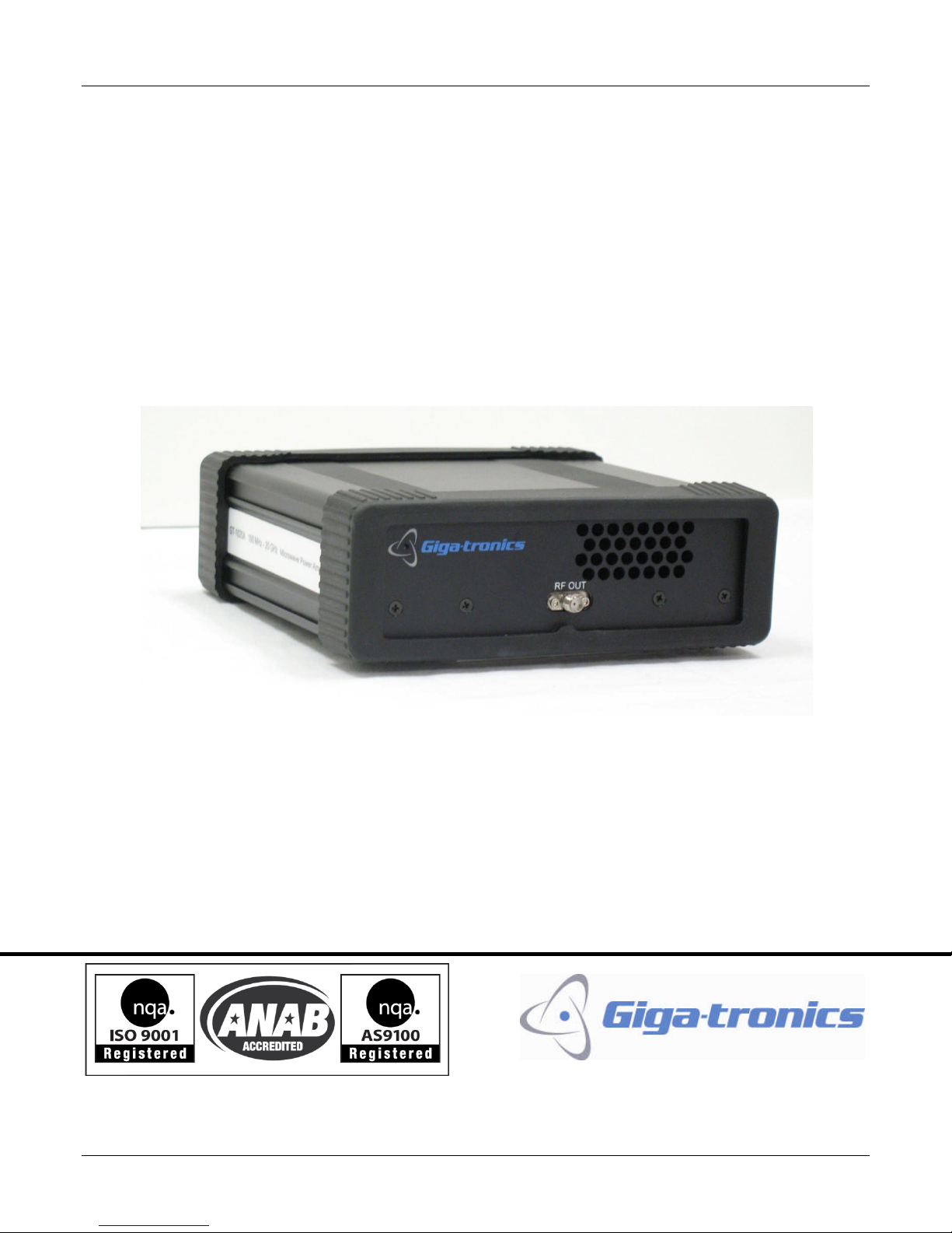
1020A 100 MHz to 20 GHz
Microwave Power Amplifier
Page 2

Giga-tronics GT
-
1020A Microwave Power Amplifier
Operation Manual, Part Number 34980, Rev. A, January 2011
All technical data and specifications in this publication are subject to change without prior notice and do not
represent a commitment on the part of Giga
-
tronics, Incorporated.
© 20
11
Giga
-
tronics Incorporated. All
rights reserved. Printed in the U.S.A.
CONTACT INFORMATION
Giga
-
tronics, Incorporated
4650 Norris Canyon Road
San Ramon, California 94583
Telephone:
800.726.4442
(only within the United States)
925.328.4650
Fax:
925.328.4700
On the Inter
net:
www.gigatronics.com
Warranty
Giga-tronics GT
-
1020A Mi
crowave Power Amplifiers are
warranted against defective materials and workmanship for one
year from date of shipment. Giga
-
tronics will at its option repair
or replace products that are proven defective during the
warranty period. This warranty DOES NOT c
over damage
resulting from improper use, nor workmanship other than Giga
-
tronics service. There is no implied warranty of fitness for a
particular purpose, nor is Giga
-
tronics liable for any
consequential damages. Specification and price change privileges
are reserved by Giga
-
tronics.
Page 3

Giga-tronics GT
-
1020A Microwave Power Amplifier
Operation Manual, Part Number 34980, Rev. A, January 2011
Regulatory
Compliance I
nformation
This product complies with
the essential requirements of the following applicable European Directives,
and carries the CE mark accordingly.
89/336/EE
C and 73/23/EEC
EMC Directive and Low Voltage Directive
EN61010
-
1 (1993)
Electrical Safety
EN61326
-
1 (1997)
EMC
–
Emissions and Immunity
Manufacturer’s Name:
Manufacturer’s Address
Giga
-
tronics, Incorporated
4650 Norris Canyon Road
San Ramon,
California 94583
U.S.A.
Type of Equipment:
Model Series Number
:
Microwave Power Amplifier
GT-1020A
Model Numbers
:
Not applicable
Declaration of Conformity on
fil
e. Contact Giga
-
tronics at the following
;
Giga
-
tronics, Incorporated
4650 N
orris Canyon Road
San Ramon, California 94583
Telephone:
800.726.4442 (only within the United States)
925.328.4650
Fax:
925.328.4700
Page 4

Giga-tronics GT
-
1020A Microwave Power Amplifier
Operation Manual, Part Number 34980, Rev. A, January 2011
Record of Changes to This Manual
Use the table below to maintain a permanent record of changes to this document. Replac
ement pages will be
issued as a TPCI (Technical P
ublication Change Instruction).
TPCI Number
TPCI Issue Date
Date Entered
Comments
Page 5

Giga-tronics GT
-
1020A Microwave Power Amplifier
Operation
Manual, Part Number 34980, Rev. A, January 2011
i
Table of C
ontents
C
HAPTER
1
S
AFETY AND
M
ANUAL
C
ONVENTIONS
................................
................................
................................
...........
1
1.1 Personal
Safety Alert
................................
................................
................................
................................
..11.2 Equipment Safety Alert
................................
................................
................................
..............................
1
1.3 Notes
................................
................................
................................
................................
.........................
1
1.4 Electrical Safety Precautions
................................
................................
................................
.......................
2
1.5 Important Operating Instructions
................................
................................
................................
...............
2
C
HAPTER
2
I
NTRODUCTION
................................
................................
................................
................................
........
3
2.1 Overview
................................
................................
................................
................................
....................
3
2.1.1 Features and Benefits of the GT
-
1020A Microwave Power Amplifier
................................
...................
3
2.2 Controls, Indicators, and Connectors
................................
................................
................................
..........
4
2.3 Receiving and Inspection
................................
................................
................................
............................
5
2.4 Prepare the GT
-
1020A for Use
................................
................................
................................
....................
6
2.4.1
Cooling
................................
................................
................................
................................
................
6
2.4.2 AC Power Requirements
................................
................................
................................
......................
6
2.5 Shipping, Repair, and Calibration
................................
................................
................................
................
6
2.5.1 Shipping the GT
-
1020A
................................
................................
................................
........................
6
2.5.2 Repairs
................................
................................
................................
................................
................
7
2.5.3 Calibration
................................
................................
................................
................................
..........
7
C
HAPTER
3
O
PERATION
................................
................................
................................
................................
.............
9
3.1 Operating Safety and Instructions
................................
................................
................................
..............
9
C
HAPTER
4
P
ERFORMANCE
V
ERIFICATION
................................
................................
................................
...................
11
4.1 Specifications
................................
................................
................................
................................
...........
11
4.2 Performance Verification
................................
................................
................................
.........................
15
Appendix A Options
................................
................................
................................
................................
...........
19
Page 6

Giga-tronics GT
-
1020A Microwave Power Amplifier
ii
Operation Manual, Part Number 34980, Rev. A, January 2011
List of Figures
Figure 1: GT
-
1020A Front Panel
................................
................................
................................
...........................
4
Figure 2: GT
-
1020A Rear Panel
................................
................................
................................
.............................
4
Figure 3: Saturated Output Power (nominal)
................................
................................
................................
......14Figure 4: G
ain (nominal)
................................
................................
................................
................................
....
14
Figure 5: GT
-
1020A Performance Verification Setup
................................
................................
..........................
15
List of Tables
Table 1: GT
-
1020A Front Panel Controls, Indicators, and Connections
................................
................................
..5Table 2: GT
-
1020A Rear Panel Controls, Indicators, and Connections
................................
................................
...5Table 3: Receiving and Inspection of the GT
-
1020A
................................
................................
..............................
5
Table 4: Operate the GT
-
1020A
................................
................................
................................
............................
9
Table 5: Frequency Range
................................
................................
................................
................................
..11Table 6: Output Power
................................
................................
................................
................................
.......
11
Table 7: Gain Flatness
................................
................................
................................
................................
........
12
Table 8: Input and Output VSWR
................................
................................
................................
.......................
12
Table 9: Additional Specifications
................................
................................
................................
......................
12
Table 10: General Specifications
................................
................................
................................
........................
13
Table 11: GT
-
1020A Performance Verification Procedure
................................
................................
...................
16
Table 12: Performance Verification Measurements
................................
................................
...........................
17
Table 13: GT
-
1020A Options
................................
................................
................................
..............................
19
Page 7
Giga-tronics GT
-
1020A Microwave Power Amplifier
Safety and Manual Conventions
Operation Manual, Part Number 34980, Rev. A, January 2011
1
Chapter 1
Safety and Manual Conventions
T
his
manual contains conventions regarding
safety and e
quipment usage as
described
below.
1.1
Personal Safety Alert
WARNING:
Indicates a hazardous situation which, if not avoided, could result in death
or serious injury.
1.2
Equipment Safety Alert
CAUTION:
Indicates a situation which can damage
or adversely affect the
GT-1020A
or associated e
quipment.
1.3
Notes
Notes are denoted and used as follows:
NOTE:
H
ighlights or amplifies an essential operating or maintenance procedure, practice, condition or
statement
.
Review this manual to become familiar with the instrument safety markings and
instructions before operation.
WARNING
CAUTION
Page 8

Safety and Manual Conventions
Giga-tronics GT
-
1020A Microwave Power Amplifier
2
Operation Manual,
Part Number 34980, Rev. A, January 2011
1.4
Electrical Safety Precautions
Any s
ervicing inst
ructions are for use by service
-
trained personnel only. To avoid personal injury, do not
perform any service unless
you are
qualified to do so.
For continued protection against fire hazard, replace the
AC line fuse only with a
fuse of the same current
rating and type. Do not use repaired fuses or short circuited fuse holders.
1.5
Important Operating Instructions
The GT
-
1020A
Amplifier does not include
an enable/disable feature to activate and deactivate the amplifier.
When connecting or disconnecting the output of the amplifier, ensure that the power switch
on the rear
of
the amplifier is in the OFF position.
When connecting the amplifier to a transmit
ting device, observe all safety procedures to ensure that the
amplifier isn’t interfering with other systems in the area. High power microwaves can adversely affect power
sensitive instruments in the area of transmission.
Exercise precautions to avoid expo
sure to radiated microwave energy at all times.
Page 9

Giga-tronics
GT-1020A Microwave Power Amplifier
Introduction
Operation Manual, Part Number 34980, Rev. A, January 2011
3
Chapter 2
Introduction
2.1
Overview
The Giga
-
tronics GT
-
1020A
Microwave Power Amplifiers
are high
-
performa
nce
solid
-
state microwave power
amplifiers. The Giga
-
tronics GT
-
1020A
provide excellent pulse fidelity, low intermodulation distortion, high
linearity and superior gain flatness without the warm
-
up time, drift or aging issues of traveling wave tube
amplifiers
(TWTA). They feature low noise figure, low harmonics and spurious content, and are highly tolerant to
load mismatch.
GT-1020A
:Frequency
R
ange
:
100 MHz
to20GHz,operational
to 10 MHz
.SMA
(f)
input and output connectors
.
2.1.1
Features and Benefits of the
GT-1020A
M
icrowave Power Amplifier
35dBnominal
gain over the
100 MHz
to20GHz frequency range
.Ideal for testing in R&D l
ab
s, ATE s
ystems, wireless communications application
s and d
efense EW
systems
.Small size
allows easily placing the amplifier close to
the device under test
.
Page 10

Introduction
Giga-tronics GT
-
1020A Microwave Power Amplifier
4
Operation Manual,
Part Number 34980, Rev. A, January 2011
Contr
ols, Indicators, and Connectors
The following pages describe all of the features shown
in Figure 1 and Figure 2 below
.
Figure
1
: GT-1020A Front Panel
Figure
2:GT-1020A Rear Panel
Page 11

Giga-tronics
GT-1020A Microwave Power Amplifier
Introduction
Operation Manual, Part Number 34980, Rev. A, January 2011
5
Controls, Indicators, and Connectors, Continued
The tables below describe the functions of the features shown in
Figure
1
and
Figure
2
on the previous page.
Table
1:GT-1020A Front Panel Controls, Indicators, and Connections
Name
Function
Power on LED
Extinguished when
AC
power
is
OFF.
Illuminated
blue
when
AC
power is
ON.
RF OUT (RF output connector)
GT-1020A: SMA (f)
Table
2:GT-1020A Rear Panel Controls, Indicators, and Connections
Name
Function
Power Switch
Switches the unit on and off.
Fuse
Field replaceable fuse
.
AC Connector
AC power input
.
RF IN (RF Input
connector)
GT-1020A: SMA (f)
Fan
Cooling fan for unit
(internal)
2.3
Receiving and Inspection
Follow the procedure in
Table
3
for receiving and inspecting the
GT-1020A
.
Table
3:Receiving
and Inspection of the GT
-
1020A
Step
Action
1.
Before opening the shipping container, inspect it
for any signs of damage.
If THERE IS evidence
of damage
;
record the location and extent of the damage and c
ontact the
shipper immediately to report the damage.
If there is NO EVIDENCE
of damage
; continue
to the next step.
2.
Open the shipping container and inspect the contents for evidence of damage.
The contents
should include
the following:
GT-1020A
Microwave Power Amplifier
Operation Manual
AC line
cord
If any
of the contents are damaged or missing, contact Giga
-
tronics immediately
. Refer to the
Contact Information on the inside of the front cover
of this manual
.
End of procedure
Page 12

Introduction
Giga-tronics GT
-
1020A Microwave Power Amplifier
6
Operation Manual,
Part Number 34980, Rev. A, January 2011
2.4
Prepare
theGT-
1020A
for Use
2.4.1
Cooling
TheGT-1020A
has an internal cooling fan. The
air intake is located on the rear
panel of the in
strument. When
using the GT
-
1020A
, ensure there are no
obstructions to the flow of air into
or out of
the instrument.
2.4.2
AC
Power Requirement
s
AC Power Requirements:
See
Table
10
on page
13
2.5
Shipping
,
Repair
, and Calib
ration
2.5.1
Shipping the
GT-1020A
If it is necessary to ship the
GT-1020A
, observe the following:
Use
the best pack
aging materials available. If possible, reuse the original shipping container.
If the original shipping container is not available
, use a strong
carton (350
lbs./
sq.in. bursting strength) or a
wooden box.
Wrap the amplifier
in heavy paper or plastic before placing it into the shipping container.
Completely fill the area
s on all sides of the amplifier
with packaging material. Take extra precaution t
o
protect the front and rear panels.
Seal the package with strong tape or metal bands. Mark the outside of the package clearly, and in bold type,
as follows:
FRAGILE
—
DELICATE INSTRUMENT
Page 13

Giga-tronics
GT-1020A Microwave Power Amplifier
Introduction
Operation Manual, Part Number 34980, Rev. A, January 2011
7
2.5.2
Repairs
The Giga
-
tronics
GT-1020A
Microwave Power Amplifier
is a
robust instrument that has been designed and built
for years of trouble
-
free service.
However, if you experience
problems with the instrument,
do the following:
1.
Contact your local Giga
-
tronics
sales office, or the factory, and be prepared to
provi
de the m
odel,
serial
number
, and any included options
of your amplifier
, and a description of the problem.
To contact the
factory direct
ly
, use the following information
:
Contacting
Giga
-
tronics
Customer Service
Email
repairs@gigatronics.com
Telephone (within
the United States)
800.726.4442
Telephone
925.328.4702
Fax
925.328.4702
2.
If it is has been determined that you must ship the
GT-1020A
to the factory or a service center for
repair, you will be issued a
Return Materials Authorization (RMA)
number. Use the RMA number in all
correspondence regarding the repair.
3.
Pack the
GT-1020A
for shipment as described in the previous section, and enclose all relevant
informatio
n regarding the problem.
4.
Ship the
GT-1020A
to the address provided by Giga
-
troni
cs Customer Service.
2.5.3
Calibration
TheGT-1020A
Microwave Power Amplifier does not require calibration
.
There are no adjustments.
For more
information, contact Giga
-
tronics.
Page 14

Giga-tronics GT
-
1020A Microwave Power Amplifier
Operation
Operation Manual, Part Number 34980, Rev. A, January 2011
9
Chapter 3
Operat
ion
3.1
Operating Safety and Instructions
DO NOT EXCEED AN
INPUT LEVEL OF
+20
dBm
INTO THE GT
-
1020A
. EXCEEDING
THIS LEVEL CAN DAMAGE THE GT
-
1020A
MICROWAVE POWER AMPLIFIER.
WHEN ENERGIZED, THE GT
-
1020A
IS CAPABLE OF SUPPLYING POWER THAT
CAN CAUSE DAMAGE OR INJURY. TAKE THE FOLLOWING PRECAUTIONS TO
ENSURE SAFE SETUP AND OPERATION:
Verify that all cables, connectors, and e
quipment connected to
theGT-
1020A
are in good condition.
Do not make connections to equipment while the output of any item of
equipment is energized.
Table
4:Operate the GT
-
1020A
Step
Action
1.Verify that the POWER switch on
the rear of the unit is OFF.
Plug the included AC
line cord into a source of AC power that meets the specifications for
power in
Table
10
on page
13
.Put the POWER switch on the
GT-1020A
in the ON position.
NOTE:
For best results, let the GT
-
1020A
warm up for
one
minute
after switching the AC power
ON.2.
Verify that the output of the microwave
signal
source is
NOT
energized
before continuing to the
next step.
3.
Con
nect the equipment to the GT
-
1020A
according to your application.
NOTE:
Verify all mating connectors
are 50 Ohm, and that they are in good condition.
4.
Energize the output of the microwave
signal
source.
5.
Adjust the output of the microwave signal sour
ce until the output from the
GT-1020A
is at the
desired level.
End of Procedure
CAUTION
WARNING
Page 15

Giga-tronics GT
-
1020A Microwave Power Amplifier
Performance Verification
Operation Manual, Part Number 34980, Rev. A, January 2011
11
Chapter 4
Performance Verification
This chapter is divided into two sections:
Specificati
ons:
this section contains all of the operating specifications that defi
ne the performance of
the GT
-
1020A
.Performance Verification:
this section contains the test proced
ure that ensures that the
GT-1020A
meets the specifications.
4.1
Specifications
NOTE:
Graphs of some of the
GT-1020A
characteristics are on page
14.Table
5:Frequency Range
Model
Specification
GT-1020A
100MHzto20GHz
,
operational
to 10 MHz
Table
6:Output Power
Parameter
Specification
10
0 MHz
to10
GHz
+28 dBm (600 mW) typical, +2
6
dBm (
4
00 mW) minimum
10to20
GHz
+27 dBm (500 mW) typical, +2
5
dBm (
3
00 mW) minimum
NOTES:
Output power is specified as minimum saturated power into
50 Oh
m load
with +
5 dBm
input,
at 23
°C ±5°C
.Input power for normal operation should
be limited to
0 dBm
maximum.
Page 16

Performance Verification
Giga-tronics GT
-
1020A Microwave Power Amplifier
12
Operation Manual,
Part Number 34980, Rev. A, January 2011
Table
7
: Gain Flatness
Range
Specifications
100 MHz to 20 GHz
±
2.5 dB typical,
±
3.5 dB maximum
NOTES:
Nominal gain is 35 dB, minimum gain > 25dB.
Gain flatness is specified as maximum variation with
-
5 dBm input and 50 Ohm load.
Table
8
: Input and Output VSWR
Connector
Frequency Range
(100 MHz
to
20 GHz)
Input, 50 Ohms
2.0:1 typical
Out
put, 50 Ohms
2.0:1 typical
Table
9
: Additional Specifications
Parameter
Specification
Stability
Unconditionally Stable
Maximum Load VSWR
3:1
Maximum Input Power
(RF)
+20 dB
m
Third Order Intercept
+35 dB
m
nominal, referenced to output
Harmonic Distortion
<-30 dB
c
nominal
Spurious
<-60 dB
c
nominal
Reverse Isolation
>
50 dB
Noise Figure
< 5 dB nominal, < 7 dB maximum
* NOTE:
Harmonics measured at +10 dBm output power.
Spurious measured at
-
5 dBm input power level
Page 17

Giga-tronics GT
-
1020A Microwave Power Amplifier
Performance Verification
Operation Manual, Part Number 34980, Rev. A, January 2011
13
Table
10:General Specifications
Parameter
Specification
Operating Temperature
0
°C to +50
°C
Storage Temperature
-20°C to +75
°C
Cooling
Forced air
Dimensions
2.5 inches H x
6.8
inches D x
7.0
inches W
(64mm H x 17
3
mm D x
178mm W)
Weight
4.5 lbs (2 kg)
RF Connectors
SMA
(f)
Power Supply
AC line input
100 t
o 240 VAC,
47to440
Hz, Single Phase
Line Power
20VAmaximum
Page 18

Performance Verification
Giga-tronics GT
-
1020A Microwave Power Amplifier
14
Operation Manual,
Part Number 34980, Rev. A, January 2011
Figure
3:Saturated Output Power
(nominal)
Figure
4
: Gain (nominal)
Page 19

Giga-tronics GT
-
1020A Microwave Power Amplifier
Performance Verification
Operation Manual, Part Number 34980, Rev. A, January 2011
15
4.2
Performance
Verification
This section
describes how to test the GT
-
1020A
to verify t
hat it meets Giga
-
tronics
specifications.
The
overall operation of the GT
-
1020A
Microwave Power Amplifier is checked using a broadband
signal source,
power sensor
,
and a power m
eter.
T
he test setup is shown in
Figure
5
. The procedure starts on the next page.
Equipment and Material
Si
gnal s
ource
:
Giga
-
tronics
2520B 20
GHz
Microwave Signal Generator
or equivalent
Power m
eter:Giga
-
tronics
8651
Bor8652
B
Power Meter or equivalent
Power s
ensor
:
Giga
-
tronics
8
0323
A,20
GHz
, 1 Watt
,
SMA
or equivalent
Test cable:
SMA
(m),20GHz test
cable
Figure
5:GT-1020A Performance Verification Setup
Note:
Connect test cable between
2520B
RF Output and GT
-
1020A
DUT RF Input.
Page 20

Performance Verification
Giga-tronics GT
-
1020A Microwave Power Amplifier
16
Operation Manual,
Part Number 34980, Rev. A, January 2011
Performance Verification, Continued
Table
11:GT-1020A Performance Verification Procedure
Step
Action
1.
Connect equipment as shown in
Figure
5.2.
Keep equipment powered off until all connections are made.
3.
Always start with signal generator RF Off.
4.
Turn equipment on (
with
RF Off) and allow to warm
up for 30 minutes.
5.
Set signal generator to the first test frequency and RF power level at
-
20 dBm.
6.
Set
power meter to first test frequency.
7.
Turn on signal generator RF output and increase RF power level to +5 dBm.
8.
Measure power output from DUT on
power meter and record the value
in
Table 1
2.9.
Set signal generator to the next test frequency
10.
Set power meter to next test frequency.
11.
Measure power output from DUT on power meter and record the value.
12.
Repeat
steps
9
thru11for
all
remaining
test frequencies.
13.
Verify measured power exceeds minimum power specification.
End of Procedure
Page 21

Giga-tronics GT
-
1020A Microwave Power Amplifier
Performance Verification
Operation Manual, Part Number 34980, Rev. A, January 2011
17
Performance Verification, Continued
Table
12
: Performance Verification Measurements
Frequency (GHz)
Minimum Power
Output
(dBm)
Measured Power Output
(dBm)
2263264
26
5
26
62672682692610261125122513251425152516251725182519252025Serial Number
Page 22

Giga-tronics GT
-
1020A Microwave Power Amplifier
Appendix A
–
Options
Operation Manual, Part Number 34980, Rev. A, January 2011
19
Appendix A
Options
This section describes the options that are available
for the GT
-
1020A
.
Table
13:GT-1020A Options
Option Number
Description
46
Add Rack Mount Kit
Page 23

Appendix A
–
Options
Giga-tronics GT
-
1020A
Microwave Power Amplifier
20
Operation Manual,
Part Number 34980, Rev. A, January 2011
Last page of Document
 Loading...